

Valor COSYFLAME TURBOCHIM 528, SECRET TURBOCHIM 527, HEARTHMASTER 527w Installer's Manual
INSTALLER GUIDE
VALOR COSYFLAME
TURBOCHIM*
(MODEL 528)
VALOR SECRET
TURBOCHIM*
(MODEL 527)
&
HEARTHMASTER
(MODEL 527w)
Rear Fan Flued
Inset Gas Fires
with Live Fuel Effect
*Patent applied for
600A945/05
Please ke e p in a safe p l ac e for fut ur e r e fe r e n c e

Please leave this Installer Guide with the user
This appliance is for use with natural gas (G20)
This appliance is for use in the United Kingdom
(GB) and the Republic of Ireland (IE) only.
CUSTOMER CARE
This Installer Guide gives sufficient details to enable the appliance to be installed
and maintained. If further information is required, our Valor AdviceLine will
be pleased to hel p.
Please telephone 0345 626341 (Local call rates apply)
2

CONTENTS
PART1: APPLIANCE DATA...........................................................................................................................................................4
PART2: GENERAL INSTALLATION REQUIREMENTS......................................................................................................4
PART 3: UNPACKING....................................................................................................................................................................9
PART 4: PREPARING FOR INSTALLATION.........................................................................................................................10
PART 5: WALL PREPARATION..................................................................................................................................................10
General...........................................................................................................................................................................................10
Brick, Stone Etc. Building. Main Case In Front Of Wall .........................................................................................................10
Brick, Stone Etc. Building. Main Case Recessed Into Wall......................................................................................................11
Timber frame building. Firebox in front of wall........................................................................................................................11
Wall preparation for flue tube. .....................................................................................................................................................12
Core drilling...................................................................................................................................................................................12
Hammer and chisel cutting..........................................................................................................................................................12
Fixing the appliance in position...................................................................................................................................................13
Provision for main loom...............................................................................................................................................................13
Prepare flue assembly ...................................................................................................................................................................13
PART 6: INSTALLATION OF ELECTRICS, FIREBOX AND FAN BOX .........................................................................14
Securing firebox to wall - cable retention...................................................................................................................................15
Securing firebox to wall using fixing brackets............................................................................................................................15
Fan box installation.......................................................................................................................................................................16
Electrical installation.....................................................................................................................................................................17
Refit the burner unit.....................................................................................................................................................................17
Electrical test..................................................................................................................................................................................18
Terminal guarding.........................................................................................................................................................................18
PART 7: GAS SUPPLY INSTALLATION..................................................................................................................................19
Preliminary Burner Checks .........................................................................................................................................................19
Check Reference Pressure ..........................................................................................................................................................20
PART 8: FITTING THE CERAMICS.........................................................................................................................................20
PART 9: CHECKS...........................................................................................................................................................................22
Recheck Control Settings.............................................................................................................................................................22
Check for spillage..........................................................................................................................................................................23
Flame supervision & spillage monitoring system......................................................................................................................23
PART 10: FRONT CASTING ASSEMBLY & FINAL REVIEW.............................................................................................24
Front casting assembly for model 527 ........................................................................................................................................24
Final review....................................................................................................................................................................................24
PART 11: SERVICING PARTS AND REPLACEMENT ........................................................................................................25
To replace the burner plaques .....................................................................................................................................................25
To Remove The Pilot Unit .........................................................................................................................................................25
To Completely Remove The Burner Unit................................................................................................................................26
To Remove The Gas Tap/F.S.D & Solenoid Assembly...........................................................................................................26
To Remove The Piezo Generator...............................................................................................................................................26
To Remove The Main Burner Elbow Injector..........................................................................................................................26
To Remove an “On” or “Off” Switch ........................................................................................................................................26
To Gain Access to the Electrical Control Components ..........................................................................................................27
To Remove the Distribution block.............................................................................................................................................27
To Remove the Fan......................................................................................................................................................................27
To remove the pressure switch ...................................................................................................................................................27
Pressure switch strip down ..........................................................................................................................................................27
Short List Of Spares......................................................................................................................................................................28
3

PART1: APPLIANC E DATA
This appliance does not contain any component manufactured from asbestos or
asbestos related products.
The appliance data label and wiring diagram are on a plate chained below the burner
and visi ble when the con t rol cover is r emoved .
Gas: Natural (G20)
Inlet pressure: 20mbar (8in w. g. )
Gross inpu t: Max. 6.0k W (20,500 Btu/h)
Min.2.2k W (7,500Btu/h)
Burner test pressure (cold ): 18.2+0.75mbar (7.3+
Gas connection: 8mm pipe
Burner injector: Bray cat. 82 size 360
Pilot & atmosph ere sensing device: SIT ref. OP 9044
Ignition: Piezo electri c . In tegral with gas ta p
Aeration: Non-adjustable
Electric a l supply: 230V ~ 50Hz AC
Fan motor rating: 55W
Fuse rating: 3A
0.3 in w.g. )
PART2: GENERAL INSTALLATION REQUIREMENTS
The installation must be in accordance with these instructions.
For the user’s protection, in the United Kingdom it is the law that all gas appliances are
installed by competent persons in accordance with the current edition of the Gas Safety
(Installation and Use) Regulations. Failure to install the appliance correctly could lead
to prosecution. The Council for the Registration of Gas Installers (CORGI) requires
its members t o w ork to recognised st a ndards.
In the United Kingdom, all electrical supply installation must be installed in
accorda nce with the current edition of the IEE Wiring Regulati ons (BS7671).
In the United Kingdom the installation must also be in accordance with:
a) All the relevant parts of local regulations.
b) The current edition of the Building Regulations issued by the Department of the
Environmen t a nd the Welsh Office or th e Buildin g Sta n dards (Scotland)
(Consolidation) Regulations issued by the Scottish Development Department.
All relevant codes of practice.
c) The relevant parts of the current editions of the following British Standards:-
BS 5440 Part 1
BS 5871 Part 2 & 3
BS 6891
In the republic of Ireland the installation must also conform with:
a) The current editio ns of:-
IS 813
ICP3
b) All relevant national and local rules in force.
c) The current ETCI National Rules for Electrical Installation.
Electrical isolation of the unit should be by means of a switched 3A fuse spur that
should be readily accessible to the user, easily identifiable and sited within reach of the
mains cable provided. It should only connect this appliance.
This fire is a fan flued appliance for installation on an outward facing wall of a
conventional home which does not have a purpose built flue or chimney.
As supplied, the appliance is suitable for homes constructed of brick, stone, etc., the
appliance can be installed into walls up to a maximum thickness as shown below.
If the fire box is in f ront of the finished wall surface: 600mm (23 5/8in ) max.
These dimensions are from the finished internal wall surface (including any surround material) to
the external wall surface.
4
Installation to a timber framed building should be in accordance with the relevant
sections of Institute of Gas Engineers publication IGE/UP/7 “Gas installations in
timber frame buildings”. Please note that advice should be sou g ht before installing in a
timber frame building since the alterations requir ed may nullify any NHBC cover relating
to the property. If in doubt, guidance should be req u ested f r om you r local authority
planning or building department.
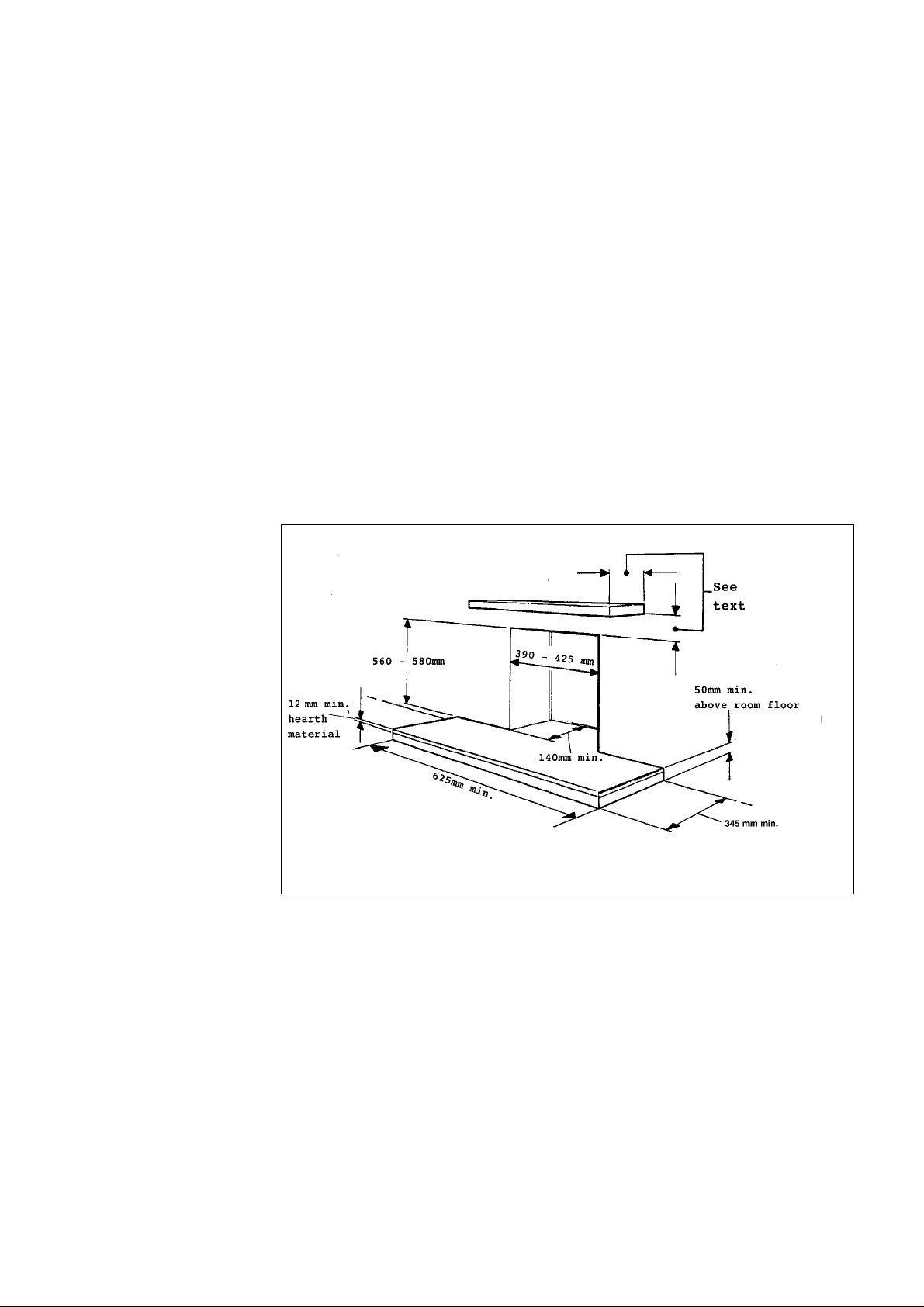
This appliance must be mounted with a non-combustible hearth (N.B. conglomerate
marble hea rths are considered a s non-combusti ble). The fire box must be moun ted on a
non-combu sti ble surfac e l evel with the hea rth. The hearth must project at least 345mm
forward of the fire box front and be at least 625mm wide (see illustrations in “wall
preparation” section). The hearth material must be at least 12mm thick. The periphery
of the hearth (or fender ) sh ou ld be at least 50mm above f l oor level to discou rage the
placing of c a rpets or rugs over it.
The surface of the hearth must be sufficientl y f lat to enable the bottom of the front
casting to be aligned horizontally. Any excessive unevenness (uneven tiles, Cotswold
stone, etc.) should be rectified.
The appliance must not stand on combustible materials or carpets.
The appli ance must not be fitted d i re ctly against a combustible wall. If the
applianc e i s to be f i tted against a wall with combustible claddi n g or skirting boa r d, such
material s mu st be r emoved from the ar ea c overed by the metal outer surrou nd of the
appliance. We suggest that the actual surround is used as a template to mark the area for
combustible cladding removal.
The applia nce can be fi tted to
a purpose made pr oprietary
class “O” 150°C surround.
The opening in the surround
or wall recess for the fire box
must be within the limits
shown i n figure 1.
The front face of the wall
should be reasonably flat over
the area which will be covered
by the fire box top a nd side
flan g es t o ensure a good seal .
The minimum height from
the top surfac e of the hearth to
the und erside of any shelf
made from wood or other
combustible mater ials is as
follows:-
• For a shelf up to 150mm
deep
Minimum height = 750mm.
• For a shelf deeper than 150mm
Minimum height = 750mm + 12.5mm for every 25mm depth over 150mm.
Note that soft wall coverings (e.g. embossed vinyl, etc.) are easily affected by heat. They
may scorch or bec ome d iscoloured wh en close to a heatin g appliance. Please bear this
in mind when installing.
The appliance must not be installed in any room which contains a bath or shower or
where steam is r egularly present.
An extractor fan may only be used in the same room as this appliance, or in any area
from which ventilation for the appliance is taken, if it does not affect the safe
performance of the appliance. Note the spillage test requirements detailed further on in
this manual. If the fan is likely to affect the appliance, the appliance must not be
installed unless the fan is permanently disconnected, or provision is made to ensure that
the fan a nd the appli a nce cannot be used at the sa me ti me.
Fig. 1 Hearth & Recess Requirements
5
A fan-powered flue system tends to depressurise the room containing the appliance.
Normally no additional ventilation should be required. In exceptional circumstances,
however the spillage check (See further on in this guide) may indicate a need for further
ventilation in order to ensu re that there is adequate a ir replac ement. If necessary seek
expert advice.
In the Republi c of Ireland (IE), permanent venti l ation must comply wi th the rules
currently in force.
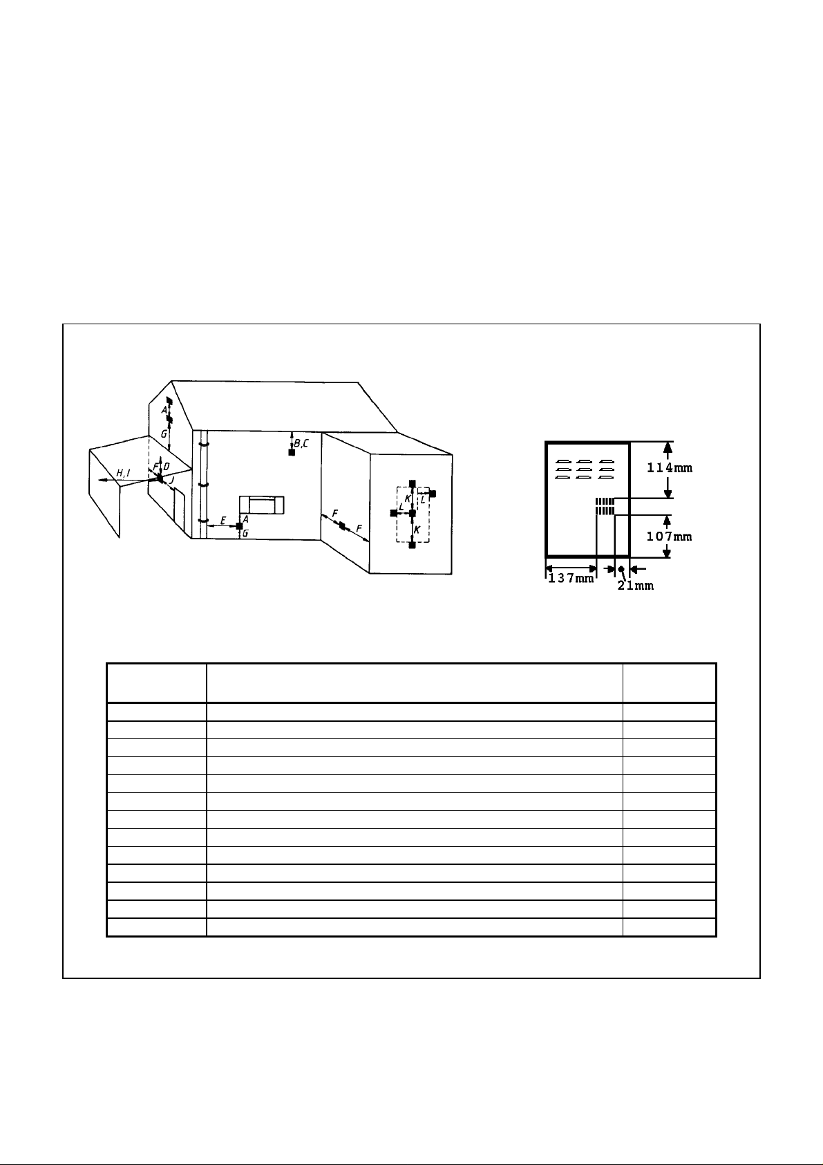
The flue terminal should be located so that the wind can blow freely across it at all times
and wher e any blockage d ue to leaves, snow, etc. is unlikely. Th e mi nimum allowable
distances from the terminal are shown in figure 2 and the table.
Note: The distances are from the edge of the vertical exit slots in the terminal not from the edges of
the rectangular box (See figure 2).
Minimum distances for terminal
positions shown in the table are
from slot openings.
Dimension Terminal Position Minimum
Distance
A Directly belo w a n opening, a ir brick, windows, etc. 300mm
B Below gutters, soil pi pes or drain pi pes 75mm
C Below eaves 200mm
D Bel ow ba lconies or ca r port roof 200mm
E From a vertical drain pipe or soil pipe 75mm
F From an intern al or external corner 200mm
G Ab ove gr ound, roof or balcon y level 300mm
H From a su rface fac ing the termi nal 600mm
I From a terminal fa c ing the terminal 1200mm
J From an opening in a car port (e.g. door, window) into dwelling 1200mm
K Vertically from a terminal on the same wal l 1500mm
L Horizontally from a terminal on the sa me wa ll 300mm
- Projection ou twa r ds from wall 55mm
Fig. 2 Allowable Terminal Positions
6

This appliance is supplied with a terminal guard. In England and Wales, the Building
Regulation s r eq uire that th e terminal gu ard is fitted if the fl ue terminal c a n come in
contact with peopl e near the building or be subjec t to d a mage. Even if the r egulations
do not deman d it, we recommend that the guar d is fitted to prevent damage or
blockage of th e flue system by leaves etc.
A concealed gas supply connection can be made through the rear panel. Visible front
connection can be from the left or right side.
Electrical connection is from the left side.
7
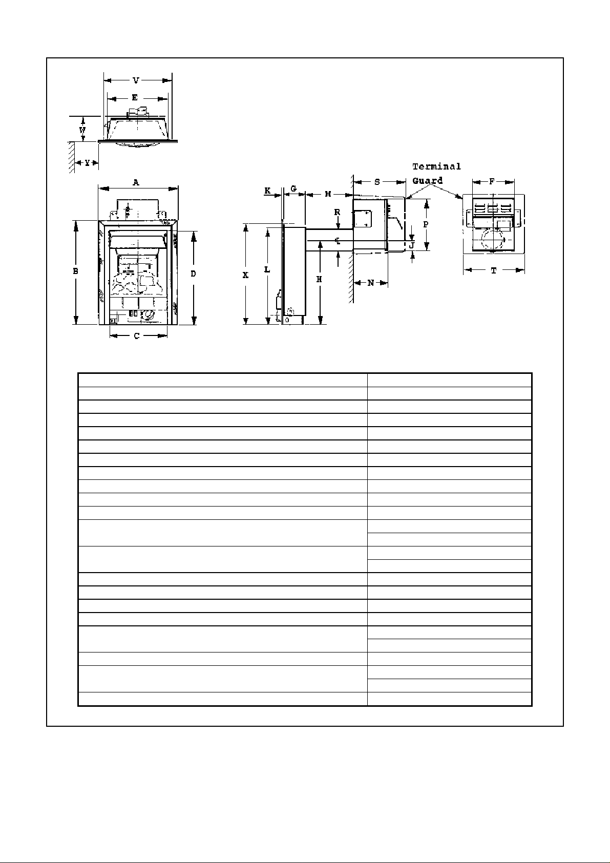
A 470mm
B 600mm
C 325mm
D 525mm
E 350mm
F 235mm
G 125mm
H 475mm
J 53mm
K5mm
L 550mm
M 600mm max. (Flue tube unc ut)
N (Fan box projection) 205mm when sited outsi d e wa ll
P 285mm
R (Flue tube diameter) 125mm
S (Terminal guard projection) 305mm
T 355mm
V (Recess width) 390mm min.
W (Recess depth) 140mm min.
X (Recess height) 560mm min .
Y (Clearance to wall etc. projecting forward of appliance firebox) 190mm min.
Fig. 3 Appliance dimensions
150mm min.
55mm when recessed in outer wall
425mm max.
580mm max.
8
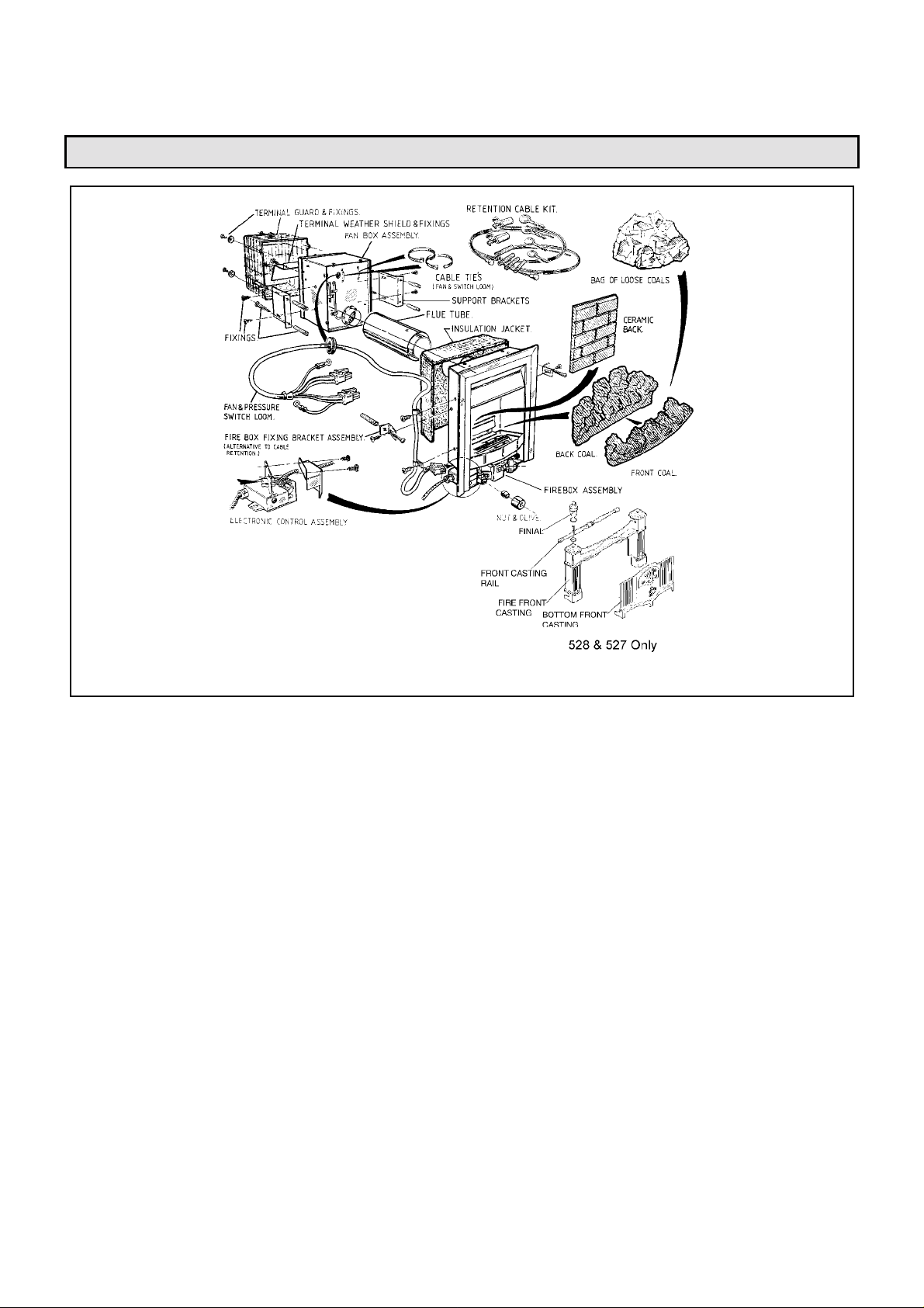
PART 3: UNPACKING
Fig. 4 Appliance units
The pack contains:
1 Burner & firebox unit with attached
Rockwool jacket
1 Fan box assembly
1Flue duct
1 Ceramic back wall
1Front base coal
1Rear base coal
1 Pack of 9 loose coal s
1 Terminal weather shield
1 Fire front casting
2 Casting f inials, bolts & nu t s (mod el 527)
1 Fron t c a sting rail (model 527)
1 Bottom front cover casting
1Template
1 Literature pack
1 Smoke match tube
1 Fan and pressur e sw itch loom
1 Nut & olive for 8mm inlet pipe
1 Retention k it ( 4 wall plugs, 4 eye bolts, 2 ten si on
adjusters and two cable assemblies).
10 Wall plugs
10 Woodscrews
2 Taptite screws (For fan box)
1 Rockwool jacket top section
2 Cable ties
1 Firebox fixing bracket assembly (2 brackets, 4 “P” clips
& 6 self tapp ing screws)
1 Termina l guard fixing assemb ly (4 screws & washers )
(Terminal guard in separate pack)
Carefully remove the contents. Take special care in handling
the ceramic fireback and the coals. Check that the li sted pa rts are
present and in good condition.
2 Rolls aluminium tape
9
 Loading...