

Valor Retrofire RA24JDNK, Retrofire Series, Retrofire RA24JDPK Installation & Owner's Manual
INSTALLATION & OWNER’S MANUAL
Retrofi re
Gas Conversion Kits RA24JDNK / RA24JDPK
Use with Valor Retrofi re Heater Models RF24JD ONLY
This appliance is certifi ed for use from 0-4500ft. For
altitudes above 4500ft see local codes.
Kit Contents
• 1 Pilot injector (see chart below)
• 1 Burner
• 1 Main burner injector (see chart below)
• 1 Minimum rate by-pass screw (see chart below)
• 1 Set of conversion labels
• 1 Set of air shutters
Tools Required
• Wrenches, to disconnect gas line
• Phillips (+) screwdriver, to remove burner module
• Small jewelers size fl at blade screwdriver, to set pressure
• Small fl at blade screwdriver, to release pressure tap on
valve
• Needle Nose Pliers, to remove by-pass screw
• Hex Allen wrench, 4 mm or 5/32”, to remove pilot injector
• Special 2-pin screwdriver tip, supplied with kit, to
remove valve cover
• Manometer, to set pressure
Specifi cations
WARNING
This conversion kit shall be installed by a
qualifi ed service agency in accordance with
the manufacturer’s instructions and all applicable codes and requirements of the authority
having jurisdiction. If the information in these
instructions is not followed exactly, a fi re, explosion or production of carbon monoxide may
result causing property damage, personal injury or loss of life. The qualifi ed service agency
is responsible for the proper installation of this
kit. The installation is not proper and complete
until the operation of the converted appliance
is checked as specifi ed in the manufacturer’s
instructions supplied with the kit.
Use this manual in conjunction with the installation manual supplied with the appliance.
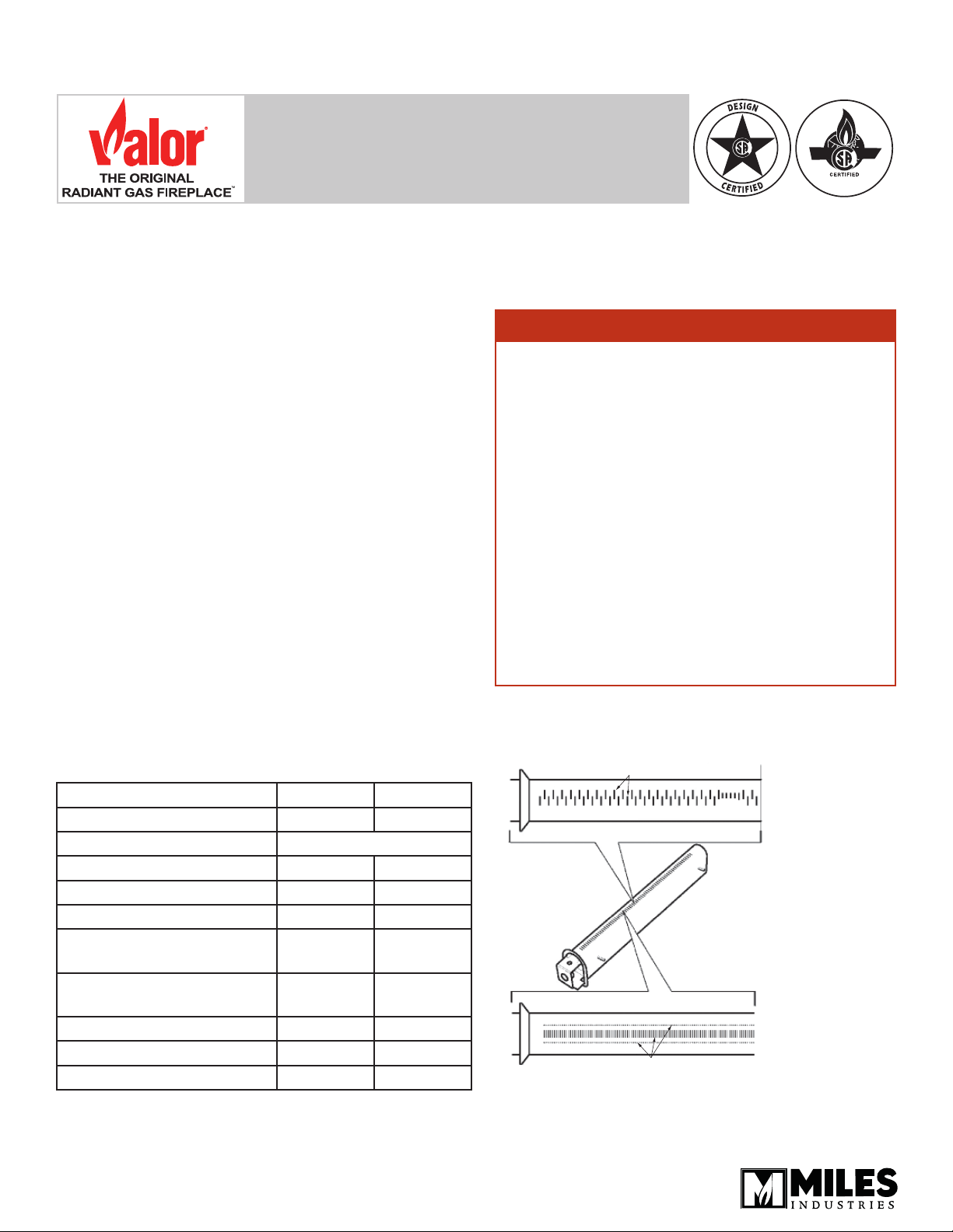
Natural Gas Burner:
Has two interlaced rows of slots
Fireplace Models RF24JDN RF24JDP
Gas Natural Propane
Altitude (Ft) 0–4,500 Feet
Input Max. (Btu/h) 20,000 18,000
Input Min. (Btu/h) 6,500 12,500
Manifold pressure (in w.c.) 3.2 9.5
Min. Supply pressure
(in w.c.)
Max. Supply pressure
(in w.c.)
Main Burner Injector 82-580 92-200
Pilot Injector 35 27
By-Pass Screw 185 125
4006631-01
© 2018 Miles Industries Ltd. All rights reserved.
5.0 11.0
10.0 14.0
Propane Gas Burner: marked “LPG”
Has single row of slots and two rows
of small holes
Conversion Procedure
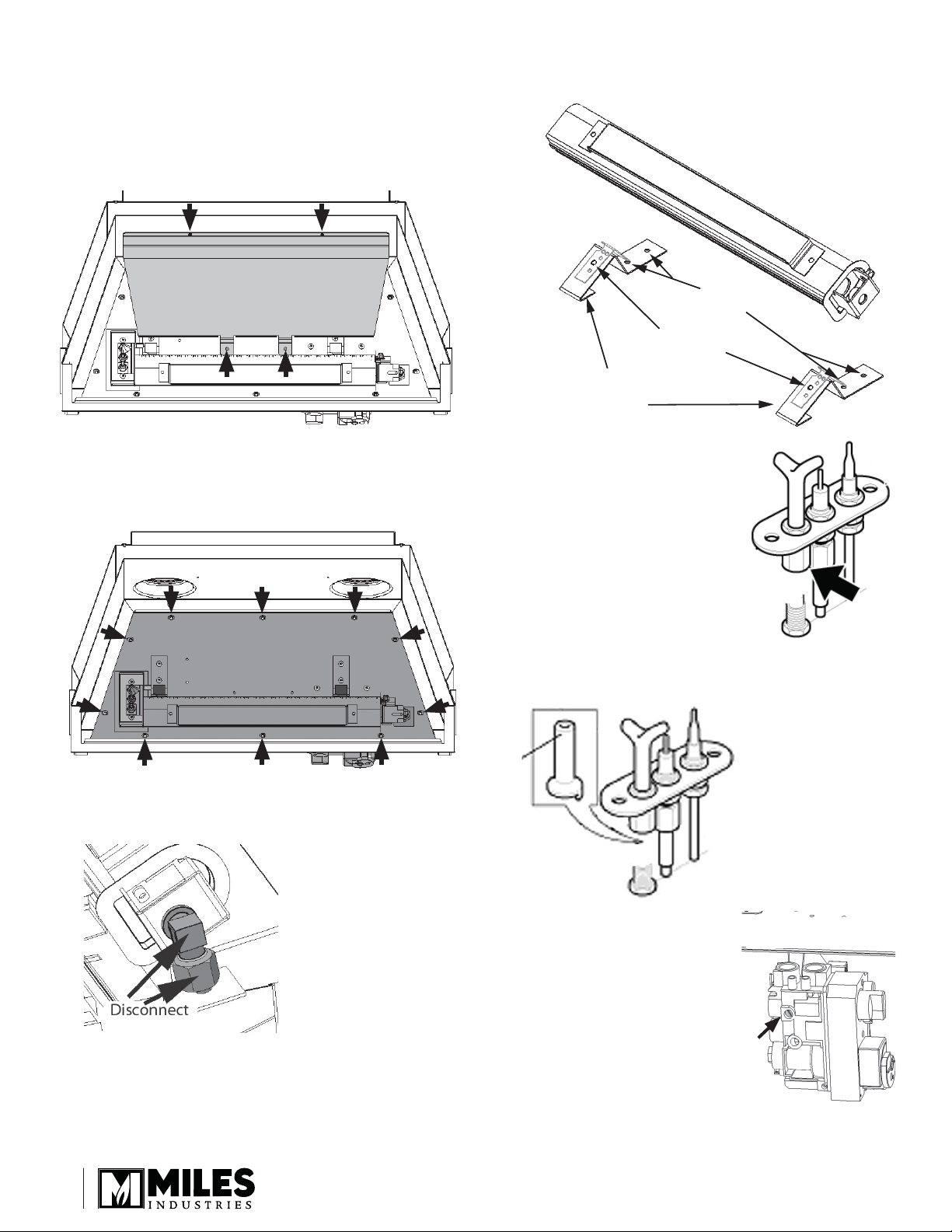
1. If the fi replace is already installed, remove window
cover with barrier screen, window, and fuel bed.
2. Disconnect the gas inlet pipe from the inlet elbow
fi tting on the valve.
3. Remove the rear log support (4 screws).
6. Remove the 6 screws (2 underside of bracket)
securing the burner brackets to the burner tray.
Fixing
screws
Burner
fixing nuts
Fixing screws
underside of
brackets
4. Remove the burner module (10 screws). If the unit
has been burned previously, it may be necessary
to pry the burner module gasket as they tend to
adhere when removed the fi rst time.
5. Disconnect the burner elbow injector from the pipe,
using a 11/16” (17 mm) wrench.
7. Detach the two burner support
brackets from the burner by
removing two nuts, using a
5/16” (8 mm) wrench.
8. Accessing the pilot assembly
from the underside of the
module, disconnect the pilot
pipe, using a 7/16” (11 mm)
wrench.
9. Remove the pilot injector. Replace with the
appropriate gas injector.
Note - The pilot
injector should be
slipped onto the
end of the pipe
from the side. The
pilot pipe, with
injector attached,
should be inserted
into the assembly.
10. Remove and replace the
minimum rate by-pass screw
minimum rate by-pass
screw location
from the valve with the
appropriately labelled by-pass
screw—see Specifi cations
table on page 1. The screw
has a rubber o-ring holding it
into the valve body and may
require prying out or removing
the screw with needle nose
pliers.
2
 Loading...