

Valor RA24PK, RA24NK, RA24BN, RA24BN BV, RA24BP Installation Instructions Manual
...
Gas Conversion Kits
RA24NK (DV), RA24PK (DV) RA24BN (BV), RA24BP (BV)
Use with Valor Retrofi re Heater Models RF24D, RF24B, RF24ID or RF24XB ONLY
Installation Instructions
This appliance is certifi ed for use from 0-4500ft. For
altitudes above 4500ft see local codes.
Kit Contents
• 1 Pilot injector, see chart for identifi cation
• 1 Main burner injector, see chart for identifi cation
• 1 Minimum rate by-pass screw
• 1 Special bit for control cover screw (for RFBV/XB only)
• 1 Set of conversion labels
Tools Required
• Wrenches, to disconnect gas line
• Phillips (+) screwdriver, to remove burner module
• Small jewelers size fl at blade screwdriver, to set pressure
• Small fl at blade screwdriver, to release pressure tap on
valve
• Needle Nose Pliers, to remove by-pass screw
• Hex Allen wrench, 4 mm or 5/32”, to remove pilot injector
• Special 2-pin screwdriver tip, supplied with kit, to
remove valve cover
• Manometer, to set pressure
Specifi cations
WARNING
This conversion kit shall be installed by a
qualifi ed service agency in accordance with
the manufacturer’s instructions and all applicable codes and requirements of the authority
having jurisdiction. If the information in these
instructions is not followed exactly, a fi re, ex-
plosion or production of carbon monoxide may
result causing property damage, personal injury or loss of life. The qualifi ed service agency
is responsible for the proper installation of this
kit. The installation is not proper and complete
until the operation of the converted appliance
is checked as specifi ed in the manufacturer’s
instructions supplied with the kit.
Use this manual in conjunction with the installation manual supplied with the appliance.
Fireplace Models RF24DVN
RF24IDN
Gas Natural Propane Natural Propane
Altitude (Ft) 0–4,500 Feet
Input Max. (Btu/h) 24,000 24,000 20,500 19,000
Input Min. (Btu/h) 10,500 10,500 12,500 12,500
Manifold pressure (in w.c.) 3.95 9.5 3.7 10.5
Min. Supply pressure (in w.c.) 5.0 11.0 5.0 11.0
Max. Supply pressure (in w.c.) 10.5 14.0 10.5 14.0
Main Burner Injector 82-580 92-260 82-580 92-200
Pilot Injector 62 30 62 30
By-Pass Screw 160 105 185 125
4000803-07
© 2011 Miles Industries Ltd. All rights reserved.
RF24DVP
RF24IDP
RF24BN
RF24XBN
RF24BP
RF24XBP
Conversion Procedure
1. Remove window, ceramic logs and bricks (if
any) from fi rebox (see RF24 installation manual).
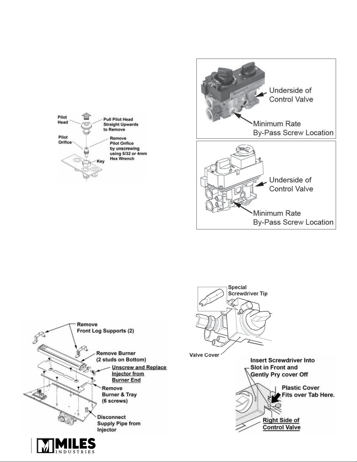
2. Remove and replace the existing pilot injector
by pulling the pilot hood off (upwards) and
unscrewing the pilot injector using a 4 mm (5/32”)
hex wrench. Set the existing injector aside.
Check the size of the new injector (see chart on
page 1), insert the new injector, tighten, then
reinstall the pilot hood lining up the slot in the hood
with the key in the holder.
3. Remove and replace the existing main burner
injector. The main burner injector may be removed
with the module in place (if space for wrenches
permits). Disconnect the piping and rotate the
injector out of the end of the burner while holding
the supply pipe down, out of the way from
underneath; loosening the 2 right hand screws
holding the burner tray will allow more separation
to rotate the injector. Alternatively, shut-off the
gas valve, disconnect the supply and remove the
burner module from the fi rebox to gain more space
to remove the injector.
Check the catalogue number stamped on the side
of the injector (see chart on page 1) and reinstall
into the end of the burner ensuring the air shutter
is installed between the injector and the burner.
Reassemble the module.
4. Remove and replace the minimum rate by-pass
screw from the underside of the valve. The screw
has a rubber o-ring holding it into the valve body
and may require prying out or removing the screw
with needle nose pliers.
RF24BV or RF24XB
RF24DV or RF24ID
5. Access the pressure adjustment screw.
a) RF24BV or RF24XB. Remove the plastic
cover from the valve using the special 2-pin
screwdriver tip supplied in the kit. Pry the
cover off the tab on the right side using a small
screwdriver.
2
 Loading...