

Valor Quantum & Urban 746, Quantum 746 Installer's Manual
5109644/01
INSTALLER GUIDE
We trust that these instructions give sufficient details to enable this appliance to be
installed and maintained satisfactorily. However, if further information is required, our
Valor Technical Helpline will be pleased to help.
Telephone 08706 061 065 (National call rates apply in the United Kingdom)
In the Republic of Ireland call 0044 08706 061 065
INSTALLER: Please leave this guide with the
owner
© Valor Heating
Quantum
&
Urban
Model 746
(GC No. 32-032-57)
INSET LIVE FUEL EFFECT GAS FIRE
THIS APPLIANCE IS FOR USE WITH NATURAL GAS (G20)
WHEN CONVERTED USING CONVERSION KIT NO. 0595221 THIS
APPLIANCE IS FOR USE WITH PROPANE GAS (G31)
THIS APPLIANCE IS SUITABLE ONLY FOR INSTALLATION IN THE UNITED
KINGDOM (GB) AND THE REPUBLIC OF IRELAND (IE).
Safety First.
Valor fires are CE Approved and designed to meet the appropriate British Standards and
Safety Marks.
Quality and Excellence.
At the heart of every Valor fire.
All Valor fires are manufactured to the highest standards of quality and excellence and
are manufactured under a BS EN ISO 9001 quality system accepted by the British
Standards Institute.
The Highest Standards
Valor is a member of the Society of British Gas Industries which works to ensure high
standards of safety, quality and performance.
Careful Installation
Valor is a CORGI registered company. All our gas fires must be
installed by a competent CORGI Registered Installer in accordance
with our Installer Guide and should not be fitted directly on to a
carpet or floor of combustible material.
Valor Heating, Erdington, Birmingham B24 9QP
www
.valor.co.uk
Because our policy is one of constant development and improvement, details may vary slightly from those
given in this publication
Page 2
INSTALLER GUIDE

CONTENTS
Section Heading Page
1. SAFETY 4
2. APPLIANCE DATA 5
3. GENERAL INSTALLATION REQUIREMENTS 6
4. PACK CONTENTS 14
5. FIREPLACE CHECK 16
5.1 Fireplace check 16
5.2 Fireplace Flue Pull 16
6. IGNITION CHECK 17
7. GAS SUPPLY CONNECTION 18
8. PREPARING APPLIANCE FOR INSTALLATION 18
9. FIREBOX INSTALLATION 20
9.1 Method 1- Front Fixing to Fireplace Surround 20
9.2 Method 2 - Cable Retention 20
9.3 Floor Sealing (All Installations) 22
10. BURNER INSTALLATION 23
10.1 Burner & Supply Pipe Installation 23
10.2.1 Lighting the burner 23
10.2.2 Operating the burner. 23
10.3 Reference Pressure Check 23
10.4 Fitting the burner tray trim. 24
11. FITTING THE FRONT SURROUND 24
11.1 Fitting The Quantum Front Surround. 24
11.2 Fitting The Urban Front Surround. 25
12. CERAMIC COALS INSTALLATION 26
13. CERAMIC PEBBLE INSTALLATION 28
14. FULL OPERATING CHECKS 32
15. SPILLAGE & FLAME SUPERVISION CHECKS 33
15.1 Check for Spillage 33
15.2 Flame Supervision & Spillage Monitoring System 33
16. FINAL REVIEW 34
17. SERVICING & PARTS REPLACEMENT 35
17.1 Checking the aeration setting of the burner. 36
17.2 To Remove the Fire Front Surround 36
17.3 To Remove the Burner Unit 37
17.4 To Remove the Pilot Unit 37
17.5 To Remove the gas valve 38
17.6 To Replace the Burner 38
17.7 To Remove the Main Burner Injector 39
17.8 To Remove the Appliance from the Fireplace 39
18. SHORT LIST OF SPARES 40
Page 3
INSTALLER GUIDE

1. SAFETY
Installer
Before continuing any further with the installation of this appliance please read the
following guide to manual handling
The lifting weight of this appliance is as below: -
Model
Weight (kG)
Quantum 10.0
Urban 10.0
One person should be sufficient to lift the fire. If for any reason this weight is
considered too heavy then obtain assistance.
When lifting always keep your back straight. Bend your legs and not your back.
Avoid twisting at the waist. It is better to reposition your feet.
Avoid upper body/top heavy bending. Do not lean forward or sideways whilst
handling the fire.
Always grip with the palm of the hand. Do not use the tips of fingers for support.
Always keep the fire as close to the body as possible. This will minimise the
cantilever action.
Use gloves to provide additional grip.
Always use assistance if required.
Page 4
INSTALLER GUIDE
2. APPLIANCE DATA
This product uses fuel effect pieces and a burner compartment rear wall
containing Refractory Ceramic Fibres (RCF), which are man-made vitreous
silicate fibres. Excessive exposure to these materials may cause irritation to eyes,
skin and respiratory tract. Consequently, it is important to take care when
handling these articles to ensure that the release of dust is kept to a minimum. To
ensure that the release of fibres from these RCF articles is kept to a minimum,
during installation and servicing we recommend that you use a HEPA filtered
vacuum to remove any dust and soot accumulated in and around the fire before
and after working on the fire. When replacing these articles we recommend that
the replaced items are not broken up, but are sealed within a heavy duty polythene
bag, clearly labelled as RCF waste. This is not classified as “hazardous waste” and
may be disposed of at a tipping site licensed for the disposal of industrial waste.
Protective clothing is not required when handling these articles, but we recommend
you follow the normal hygiene rules of not smoking, eating or drinking in the work
area and always wash your hands before eating or drinking.
This appliance does not contain any component manufactured from asbestos or
asbestos related products.
* When converted using Kit 0595221
The appliance data label is located on a plate at the base of the fire. This can be seen by
removing the lower hanging trim.
Page 5
INSTALLER GUIDE
Gas
Natural (G20) Propane (G31) *
Inlet Pressure 20mbar 37mbar
Input - Max. (Gross) 6.0kW (20,500Btu/h) 6.1kW (20,800Btu/h)
Input - Min. (Gross) 2.3kW (7,850Btu/h) 3.8kW (12,965Btu/h)
Inlet Test Pressure (Cold)
20.0 ± 1.0mbar (8.0 ± 0.4in
w.g.)
37.0 ± 1.0 mbar (14.85 ±
0.4in w.g.)
Gas Connection 8mm pipe 8mm pipe
Burner Injector Stereomatic Cat 82 - 069 Stereomatic Size 128
Pilot & Atmosphere Sensing
Device
Copreci Ref. O.D.S
21500/166
Copreci Ref. O.D.S
21500/166 Fitted with RBM
180 - 02 injector
Ignition
Piezo Electric. Integral with
Gas Tap
Piezo Electric. Integral with
Gas Tap
Aeration See section 17.1 Non-adjustable
3. GENERAL INSTALLATION REQUIREMENTS
3.1 The installation must be in accordance with these instructions.
For the user’s protection, in the United Kingdom it is the law that all gas appliances are
installed by competent persons in accordance with the current edition of the Gas Safety
(Installation and Use) Regulations. Failure to install the appliance correctly could lead
to prosecution. The Council for the Registration of Gas Installers (CORGI) requires its
members to work to recognised standards.
In the United Kingdom the installation must also be in accordance with:
All the relevant parts of local regulations.
All relevant codes of practice.
The relevant parts of the current editions of the following British Standards: BS 715 BS 1251 BS 1289 Part 1 BS EN 1806
BS 4543 Part 2 BS 5440 Part 1 BS 5440 Part 2 BS 5871 Part 1
BS 6461 Part 1 BS 6891
In England and Wales, the current edition of the Building Regulations issued by the
Department of the
Environment and the
Welsh Office
In Scotland, the current
edition of the Building
Standards (Scotland)
Regulations issued by
the Scottish Executive.
In Northern Ireland, the
current edition of the
Building regulations
(Northern Ireland) issued
by the Department of the
Environment for
Northern Ireland.
In the republic of Ireland
the installation must be
carried out by a
competent person and
installed in accordance with:
a) The current edition of IS 813 “Domestic gas installations”
b) All relevant national and local rules in force.
c) The current building regulations
Page 6
INSTALLER GUIDE
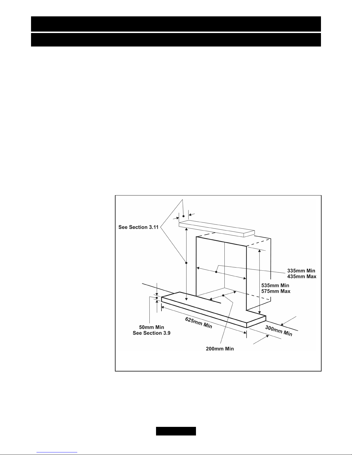
Figure 1. Hearth and Fireplace Opening Dimensions
Where no specific instructions are given, reference should be made to the relevant
British Standard Code of Practice.
3.2 In the United Kingdom, as supplied, this appliance can be installed in the
following situations: -
3.2.1 A masonry chimney with a minimum diameter of 175mm (7”) free from any
obstruction, and with any damper or restrictor plate in the chimney removed or secured,
and having a minimum effective flue height of 3m (10ft). A masonry chimney having a
correctly installed flue liner to BS715 and with a minimum flue diameter of 125mm is
also acceptable. Chair brick removal may not be required providing at least 50mm
clearance is available from the flue outlet to any fireplace component. The appliance is
designed to cater for low lintel installations (min height 505mm) providing a minimum
distance of 25mm is maintained between the lintel and the front face of the fireplace
(i.e. 25mm rebated fire surround).
3.2.1.1 ‘Hole-in-the-wall’
Installations
It is recommended that a hearth should be installed as in figure 1.
If a hearth is not fitted, the fire must be installed so that the distance from the
base of the fireplace opening in the wall to the finished floor level is at least 72mm.
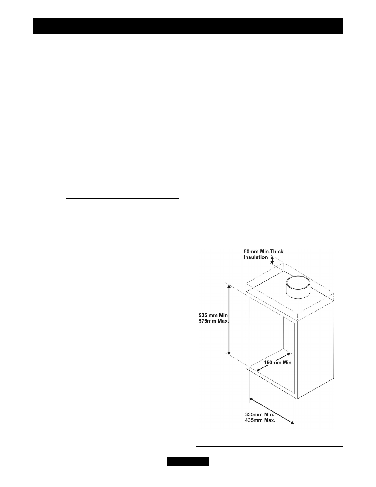
3.2.2 To a fireplace incorporating a metal flue
box conforming to BS715 with a minimum
internal depth of 150mm. Incombustible
mineral wool insulation of not less than
50mm thickness must be applied to the top
surface of the firebox (See figure 2) and it
must stand on a non-combustible hearth. See
figure 1.
3.2.3 To a fireplace that has a precast
concrete or clay flue block system
conforming to BS1289 or BS EN 1806. The
appliance is suitable for installations
conforming to older versions of BS1289 as
well as the current edition. The flue blocks
must have a minimum width not less than
63mm and a cross-sectional area not less than
13,000mm
2
.
Older editions of BS1289
required a cross-sectional area of 13,000mm2.
Page 7
INSTALLER GUIDE
Figure 2. Metal Flue Box
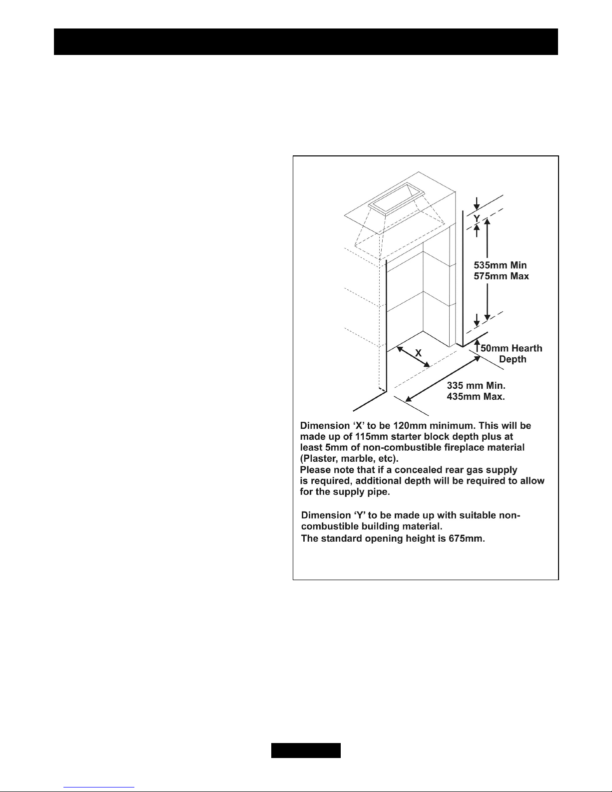
The current revision of the standard requires 16,500mm2. This appliance is suitable in
both cases. The total depth of the opening measured from the finished front of the
fireplace (Including plaster, surround etc.) must be not less than 120mm. See figure 3.
The current versions of BS1289 and BS EN 1806 recommend that there should be an air
space or insulation between the flue blocks and the plaster because heat transfer may
cause cracking on directly plastered
flues. However, generally this appliance
is suitable for installations under all
circumstances unless there is a history of
cracking problems. Remember that faults
such as cracking may be caused by
poorly built and restrictive flues, e.g.
mortar extrusions, too many bends, flue
heights below three metres, restrictive
terminations, etc.
3.2.4 If the fireplace opening is greater
than the acceptable dimensions given in
this guide, do not use the back of a fire
surround or marble to reduce the
opening. This may cause cracking of the
surround back or marble.
3.3 The following flues are suitable:
225mm x 225mm conventional brick
flue.
If a flue liner is used, it must be a
minimum of 125mm diameter. The liner
must be sealed to the surrounding area
above the fireplace opening and to the
top of the chimney. An approved terminal
must be fitted.
A properly constructed precast flue conforming to B.S 1289 or BS EN 1806.
A flue pipe with a minimum diameter of 127mm. See B.S 6461 Part 1 for suitable
materials. Metal flue pipes must comply with B.S 715.
3.3.1 The minimum effective height of the flue must be 3m.
3.3.2 The flue must be clear of any obstruction and its base must be clear of debris.
3.3.3 The flue must be completely sealed so that combustion products do not come into
contact with combustible materials outside the chimney.
3.3.4 The flue must serve only one fireplace.
Page 8
INSTALLER GUIDE
Figure 3. Pre-cast Fireplace

3.4 The flue must conform to BS 5440: Part 1 in design and installation.
The flue, measured from the bottom of the fireplace opening to the bottom of the
terminal, shall be not less than 3m in actual vertical height. When calculated in
accordance with BS 5440: Part 1 Annex A, the minimum equivalent height of the flue
shall be 2.0m of 125mm dia. flue pipe.
3.5 The flue must not be used for any other appliance or application.
3.6 Any chimney dampers or restrictors should be removed. If removal is not
possible they must be fixed in the open position.
3.7 If the appliance is intended to be installed to a chimney, which was previously
used for solid fuel, the flue must be swept clean prior to installation. All flues should be
inspected for soundness and freedom from blockages.
3.8 If the fireplace opening is an underfloor draught type, it must be sealed to stop
any draughts.
3.9 The appliance must be mounted behind a non-combustible hearth (N.B.
conglomerate marble hearths are considered as non-combustible). The appliance can be
fitted to a purpose made proprietary class “O”-150°C surround. The hearth material
must be at least 12mm thick. The periphery of the hearth (or fender) should be at least
50mm above floor level to discourage the placing of carpets or rugs over it.
The appliance must not stand on combustible materials or carpets (See figure 1).
3.10 The front face of the fireplace should be reasonably flat over the area covered by
the hotbox top and side flange seals to ensure good sealing. These faces should be made
good if necessary.The fireplace floor should be reasonably flat to ensure that a good seal
with the hotbox can be made.
Page 9
INSTALLER GUIDE
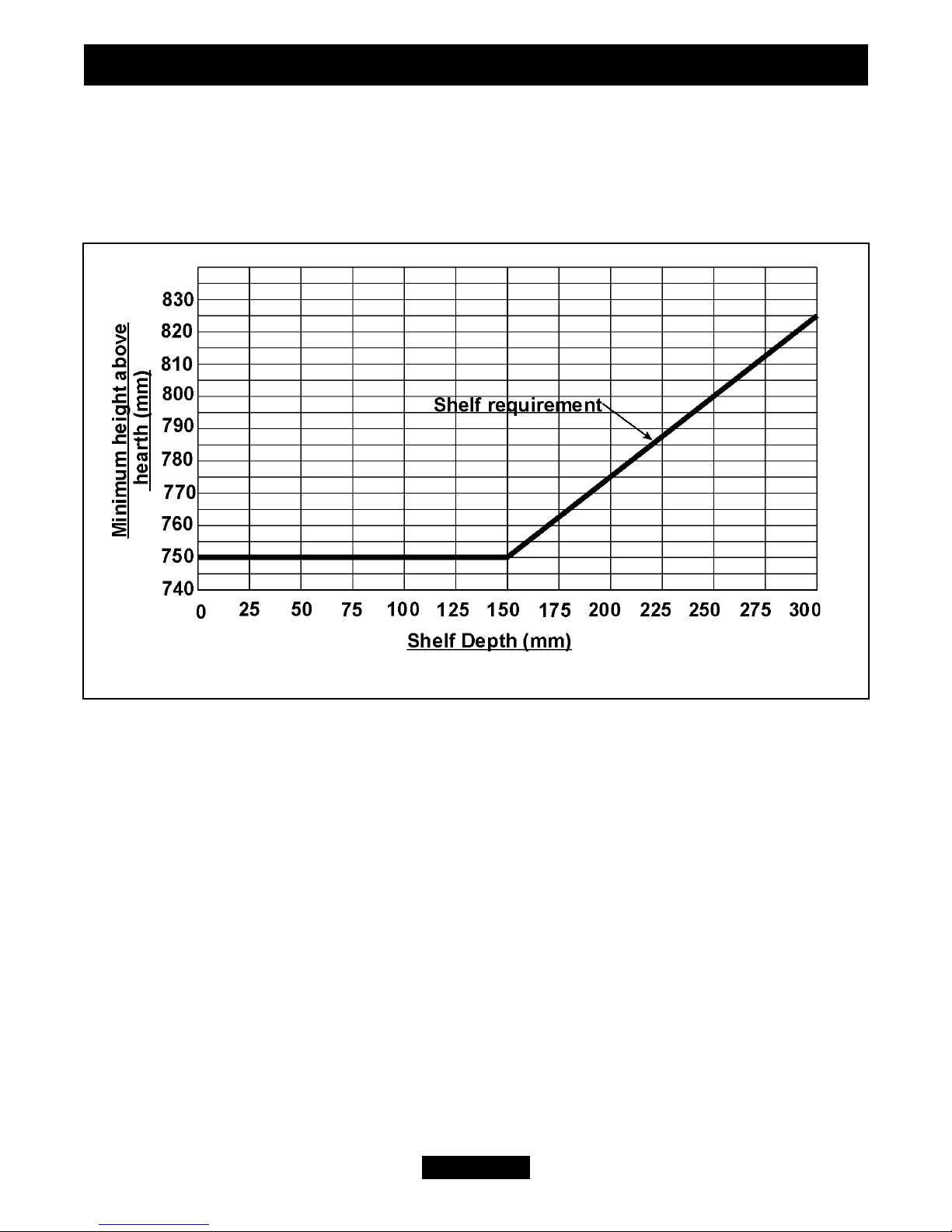
3.11 The minimum height from the top surface of the hearth to the underside of any
shelf made from wood or other combustible materials is detailed below.
• For a shelf up to 150mm deep: Minimum height = 750mm.
• For a shelf deeper than 150mm: 150mm + 12.5mm for every 25mm depth over
150mm. (See Graph 1)
3.12 Note that soft wall coverings (e.g. embossed vinyl, etc.) are easily affected by
heat. They may scorch or become discoloured when close to a heating appliance. Please
bear this in mind when installing.
3.13 The appliance must not be installed in any room, which contains a bath, or shower
or where steam is regularly present.
3.14 An extractor fan may only be used in the same room as this appliance, or in any
area from which ventilation for the appliance is taken, if it does not affect the safe
performance of the appliance. Note the spillage test requirements detailed further on in
this manual. If the fan is likely to affect the appliance, the appliance must not be
installed unless the fan is permanently disconnected.
3.15 Normal adventitious ventilation is usually sufficient to satisfy the ventilation
requirements of this appliance. In GB reference should be made to BS 5871 Part 2 and
in IE reference should be made to the current edition of IS 813 “Domestic gas
Page 10
INSTALLER GUIDE
Graph 1. Combustible shelf clearances
Installations” which makes clear the conditions that must be met to demonstrate that
sufficient ventilation is available
3.16 Propane gas appliances must not be installed in a room, which is built entirely
below ground level (See BS 5871 Pt2).
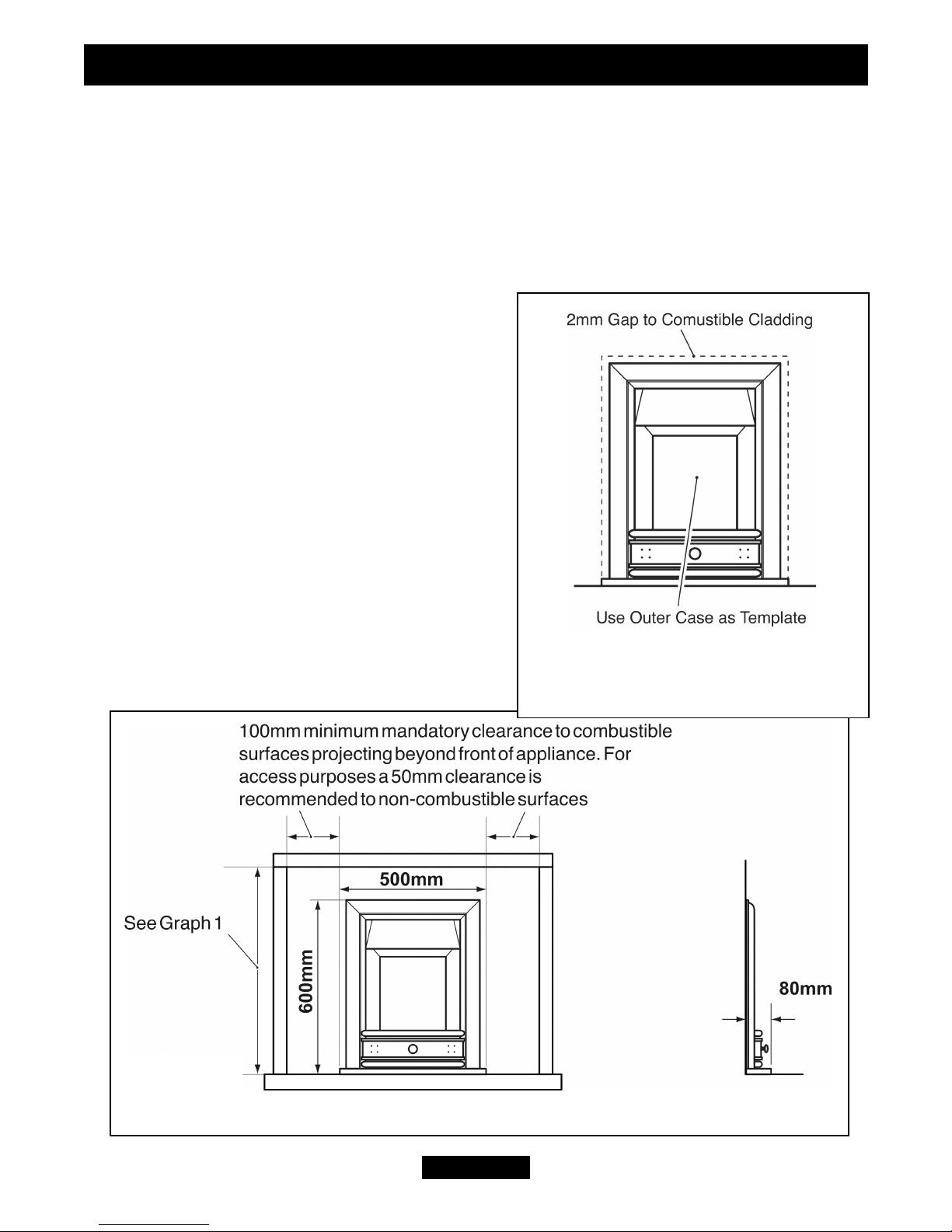
3.17 If the appliance is to be fitted against a wall with combustible cladding, the
cladding must be removed from the area
covered by the outer surround. The cladding
must also not touch the surround. (See figure 4).
We suggest that the actual surround is used as a
template to mark the area for combustible
cladding removal and that this area is increased
by at least 2mm all round.
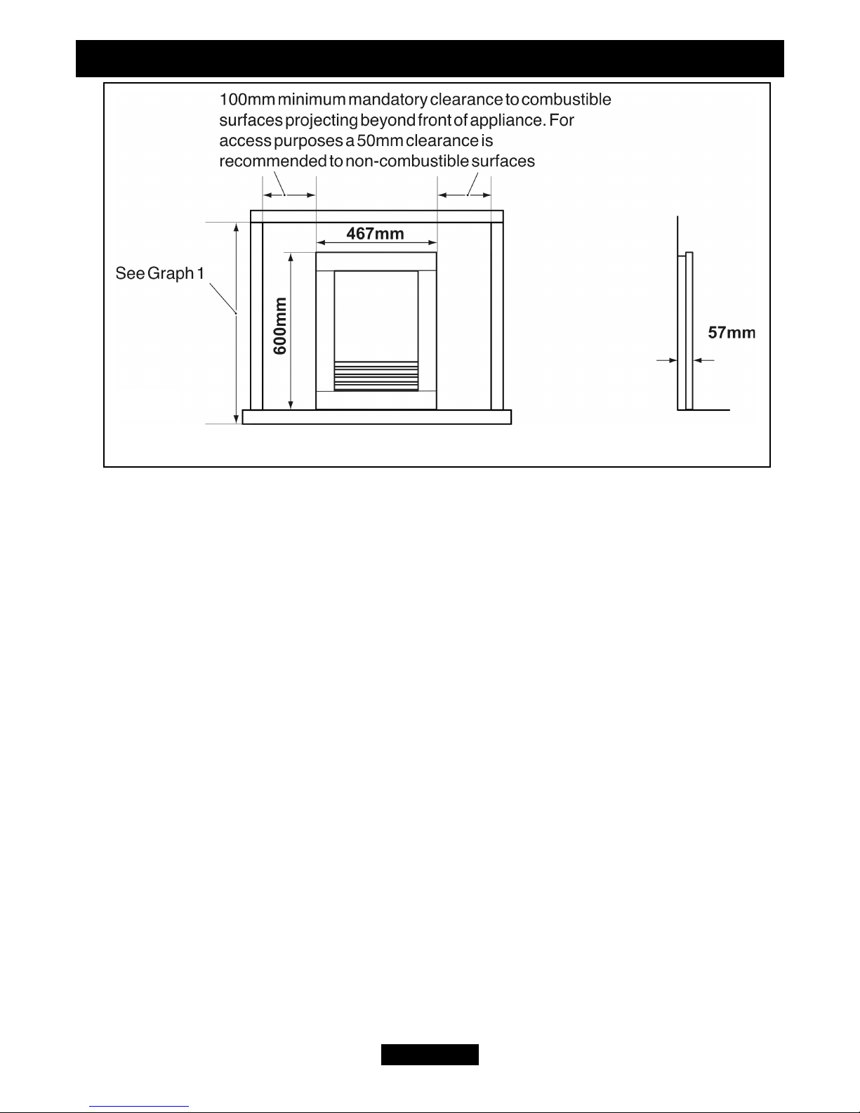
3.18 The minimum allowable distance from the
outside of the appliance case to a corner wall
having combustible material or any other
combustible surface which projects beyond the
front of the appliance is shown in figure 5.
A 50mm access clearance from a noncombustible surface is necessary at the left side.
See figure 5.
Page 11
INSTALLER GUIDE
Figure 5. Appliance dimensions
Figure 4. Removal of Combustible
cladding (Shown with Quantum
surround)
Quantum
3.19 Proprietary terminals must comply with BS 715 or BS 1289. Any terminal or
termination must be positioned in accordance with BS 5440 Part 1 to ensure that the
products of combustion can be safely dispersed into the outside atmosphere. Where the
appliance is connected to an unlined brick chimney it is generally unnecessary for the
chimney pot to be replaced or for a terminal to be fitted unless the flue has a diameter
smaller than 170mm.
3.20 The appliance is fitted with an A.S.D (Atmosphere sensing device). If the
appliance closes down after a period of operation for no apparent reason, the consumer
should be informed to stop using the appliance until the installation and appliance have
been thoroughly checked. The A.S.D will shut the appliance down if an unacceptable
amount of harmful products of combustion accumulate. Under no circumstances should
the A.S.D be altered or bypassed in any way. Only a genuine manufacturers replacement
part should be fitted. The individual A.S.D components are not replaceable.
3.21 A fireguard complying with BS 8423 should be fitted for the protection of young
children, the elderly, or the infirm.
Page 12
INSTALLER GUIDE
Figure 5 Continued. Appliance dimensions
Urban

Page 13
INSTALLER GUIDE
 Loading...