

Valor President 520AN, President 520AP Installation & Operation Manual
GAS FIRED VENTED ROOM HEATERS
ine or other flammable
vapors and liquids in the vicinity of this or any
Do not touch any electrical switch; do not use
pplier from a
neighbor’s phone. Follow the gas supplier’s
If you cannot reach your gas supplier, call the
Installation and service must be performed by a
qualified installer, service agency or the gas
he information in this manual is
not followed exactly, a fire or explosion may result
causing property damage, personal injury or loss of
MODEL 520AN
For Natural Gas
MODEL 520AP
For L P G (Propane) Gas
President
WARNING: If t
life.
− Do not store or use gasol
other appliance.
− WHAT TO DO IF YOU SMELL GAS
• Do not try to light any appliance.
•
• Immediately call your gas su
•
−
supplier
This appliance is a domestic room heater. It must not
be used for any other purpose such as drying clothes etc.
any phone in your building.
instructions.
fire department.
INSTALLATION & OPERATION MANUAL
Please read this manual before installing and operating your heater.
Please keep this manual for future reference.
(Vous pourrez vous procurer un manuel en langue Française chez votre concessionaire)
600A671/02

CONTENTSCONTENTS
Safety information 3
Installation instructions 4
• General
• Rates
• Orifice data
• Clearances
• Floor requirements
• Draft hood
• Venting
• Optional accessories
• Possible installations
• Contents of packs
• Assembling outer cast-iron case
• Heater preparation
• Ignition spark check
• Gas supply connection
• Log installation
• Operation check
• System pressure check
• Venting check
• Aeration adjustment
• Completion of assembly
• Final checks
Operating procedure 14
• Lighting if igniter fails
• Safety warnings
• Lighting instructions
Cleaning 17
Periodic checks 17
Calling for service 17
Servicing information for qualified engineer 18
• Burner tube removal
• Electrode removal
• Pilot & cross lighting burner removal
• Pilot jet removal
• Regulator removal
• Control valve & ignition generator removal
• Thermocouple removal
Page
4
4
4
5
5
5
5
5
5
6
6
7
8
8
9
10
10
10
11
11
13
14
15
16
18
18
18
18
19
19
19
2

SAFETY INFORMATIONSAFETY INFORMATION
Due to high temperatures, the appliance should be
located out of traffic and away from furniture and
draperies.
Children and adults should be alerted to the hazards of
high surface temperatures and should stay away to
avoid burns or clothing ignition.
Young children should be carefully supervised when
they are in the same room as the appliance.
Clothing or other flammable material should not be
placed on or near the appliance.
The glass window unit must be put back in place prior
to operating the appliance if it has been removed for
servicing or cleaning.
Never operate with broken or damaged window glass.
This appliance should be installed and repaired by a
qualified service person.
The appliance should be inspected before use and at
least annually by a professional service person. More
frequent cleaning may be required due to excessive
lint from carpeting, bedding material, etc. It is
imperative that control compartments, burners and
circulating air passageways of the appliance are kept
clean.
Keep curtains, clothing, furniture and other flammable
materials at least 36ins (900mm) from the front and top
of the appliance
When operating your new room heater for the first time, some vapors may be released which may cause a slight odor and could possibly set off any
smoke detection alarms in the immediate vicinity. These vapors are quite normal on new appliances. They are totally harmless and will disappear after a
few hours use.
Keep the appliance area well clear and free from
combustible materials, gasoline and other flammable
vapors and liquids.
If any changes are made to the room construction in
the vicinity of the appliance after installation (e.g.
additional mantle etc.) make sure that the changes
conform to the installation requirements in this manual.
Never attempt to burn paper or any other material in
the appliance.
Keep the base of the appliance below the ashlip and
the area between the outer case and the wall clear to
prevent obstruction of air flow to the appliance.
This appliance must be properly connected to a
venting system. The appliance is equipped with a vent
safety shutoff system designed to protect against
improper venting. Operating when not connected to a
properly installed and maintained venting system or
tampering with the shutoff system can result in carbon
monoxide (CO) poisoning and possible death.
The venting system should be checked periodically.
Recent trends in home improvement and new tighter
construction techniques have contributed to problems
with venting. If you suspect that your appliance is not
venting properly, do not operate. Seek expert advice.
Do not use this appliance if any part has been under
water. Immediately call a qualified service technician to
inspect the appliance and to replace any part of the
control system and any gas control which has been
under water.
NOTE
3
INSTALLATION INSTRUCTIONS
1. GENERAL
This appliance is certified by International Approval
Services for use in Canada and the USA.
The installation must conform with local codes or, in the
absence of local codes, with the current
CAN/CGA-B149 installation code in Canada or the current
National Fuel Gas Code, ANSI Z223.1 in the USA. Only
qualified licensed or trained personnel should install the
appliance.
The appliance rating plate is on the inner face of the back
panel at the left side.
Burner Type: Aerated front and rear simplex tubes with
combined pilot and cross lighting burner.
Gas Connection: A 3/8" N.P.T elbow connector is provided
for connection to the appliance inlet pipe located at the
center back.
Rates (Btu/h)
Natural Gas
Altitude
Max. Min.
(Ft)*
Input 0-2000 20,000 7,700
2000-4500 17,800 7,000
Output 0-2000 15,000 5,300
2000-4500 12,500 4,900
* Altitudes above 2000ft require conversion kit 525HACK
Propane
Altitude (Ft) Max. Min.
Input 0-4500 17,000 8,750
Output 12,750
Orifice Data
For verification only. Do not attempt to drill or otherwise
modify appliance output.
Gas Type No of
Dia (ins)
holes
Natural Pilot AMAL 40 1 0.022
Front Cat 18-
300
Rear Cat 99-
230
Propane Pilot Cat 960-
10
Front Cat 960-
110
Rear Cat 960-
100
7 0.025
7 0.022
1 0.0094
1 0.035
1 0.034
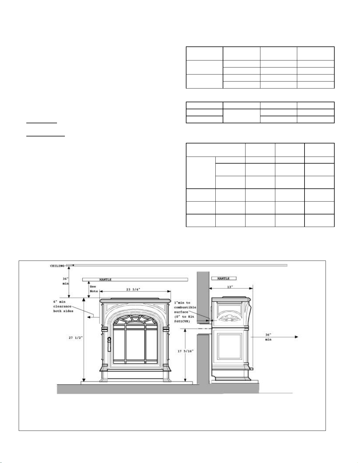
Mantles: For a mantle not more than 7” deep - minimum clearance is 6” above extreme top surface of heater. For mantle of greater depth
add 1/2” extra clearance for each extra 1” of mantle depth.
Fig.1 Dimensions & clearances
4

1.1 CLEARANCES:
Make sure that the minimum clearances to combustible materials
are maintained during installation including adequate space for
the proper operation and servicing of the heater. The minimum
clearances from the heater to combustible materials are shown in
figure 1. The combustion air opening below the ashlip assembly
and the clearance at the sides of the case rear must not be
obstructed.
1.2 FLOOR:
Do not place the heater on carpeting, vinyl or other soft surfaced
floor coverings. Install only on hard surfaced materials.
It is recommended for aesthetic considerations and ease of
maintenance that the heater is installed on a hearth finished with
brick, ceramic tile, marble etc. Raising the hearth slightly will help
to minimize dust and lint accumulation under the unit. The
recommended minimum hearth size is 32” wide x 15” deep.
If however, the heater is installed directly on flooring of
combustible material other than wood, it must be installed on a
metal or wood panel extending the full width and depth of the
heater.
1.3 DRAFT HOOD:
This heater has a draft hood built into its back and draws its air
from either side. It must not be altered or obstructed. The draft
hood must be in the same atmospheric pressure zone as the
combustion air inlet to the heater.
1.4 VENTING:
This heater is a vented appliance and must be connected to a
chimney or flue in accordance with the national and local codes.
For added safety, this heater is equipped with a vent sensor system
which will react to incorrect venting by shutting down the gas
supply. The thermally activated sensor switch is located within
the draft hood to detect either a blocked or disconnected vent.
Certain backdraft conditions may also activate the switch.
1.5 OPTIONAL ACCESSORIES:
The following kit can be used with this appliance:#401CVK Concealed Vent Kit required for use with a new zero
clearance type installation. It allows the heater to be installed with
type B metal vent concealed behind a wall or partition and/or in a
chase.
Full installation and operating instructions are supplied with the
kit.
For full details above this kit, contact your dealer.
1.6 POSSIBLE INSTALLATIONS
This appliance can be installed:
1. As a retrofit
a. To an existing masonry fireplace and chimney
b. To an existing factory built zero clearance type fireplace with a
factory built chimney.
The fireplace must be built in accordance with the national, state,
provincial or territorial building code recognized by the authority
having jurisdiction, or the National Fire Protection Association
code in the USA
Any flue damper must be removed or locked open.
The chimney must be swept and both chimney and fireplace
checked for soundness before installation of the heater.
If local codes dictate or if condensation is a problem, a flue liner
must be installed. Use a flue liner that is approved by the
enforcing authority and that is installed in accordance with the
manufacturers instructions. If a flexible liner system is used,
5
ensure that no sags or dips are allowed to occur where the liner
connects to the heater (figure 2).
2. Free standing with connection to an approved chimney or vent
maintaining the clearances shown in figure 1.
3. As a zero clearance installation fitted with the optional
#401CVK Concealed Venting Kit.
This kit allows the heater to be installed with a type B metal vent
concealed behind a wall or partition and/or in a chase. The
venting kit is designed for a 4” round flue. The kit is shown in
figure 3.
Clearances to combustible materials are: Outside edges of
framing plate = 0”. From any part of the flue adapter box
= 1”. Clearances from the connecting elbow are
determined by local codes or, in the absence of local codes,
with the current CAN/CGA1-B149 Installation Code in
Canada or the current National Fuel Gas Code, ANSI
Z223.1 in the USA
Fig. 2 Flexible chimney liner
Fig. 3 Concealed vent kit installation
2. UNPACKING THE HEATER AND CASE
CONTENTS OF THE PACKAGES
Box 1 of 3 (Heat engine)
The carton contains the following:1 Heater assembly
3 Ceramic logs (packed in the heater)
1 Flue collar
1 Flue collar extension
1 Wall spacer
1 Smoke channel (Venting check)
1 Control knob
1 Control shaft
8 Threadcutting screws for flue collar & smoke channel
2 Plastic caps for foot screws
1 Caution/Instruction position label
2 Nuts and lockwashers for wall spacer
2 Flat washers and machine screws for
arched lintel fixing
Box 2 of 3 (Outer case)
2 Side Panels (outer case)
1 Door assembly (outer case)
Box 3 of 3 (Outer case)
1 Top Plate (outer case)
1 Arched lintel (outer case)
1 Ashlip/front feet assembly (outer case).
Remove the contents carefully to prevent damage. Some items
may be contained in
the packaging
fitments - Examine
carefully before
discarding. Check
that all the items are
present and
undamaged.
Note the weight of
the component on
the outside of each
box.
3. ASSEMBLING THE CAST IRON OUTER CASE
Please read these instructions fully before attempting to install the
Outer Case for the first time.
THE OUTER CASE COMPONENTS ARE HEAVY
The cast-iron outer case supplied with President is a high quality
casting weighing around 120lbs in total, therefore it is supplied as
individual components that are easily assembled together to form a
whole. The weight of the heaviest piece is 28 lb. If you have any
doubt of your ability to easily assemble these components, you
should ask someone to assist.
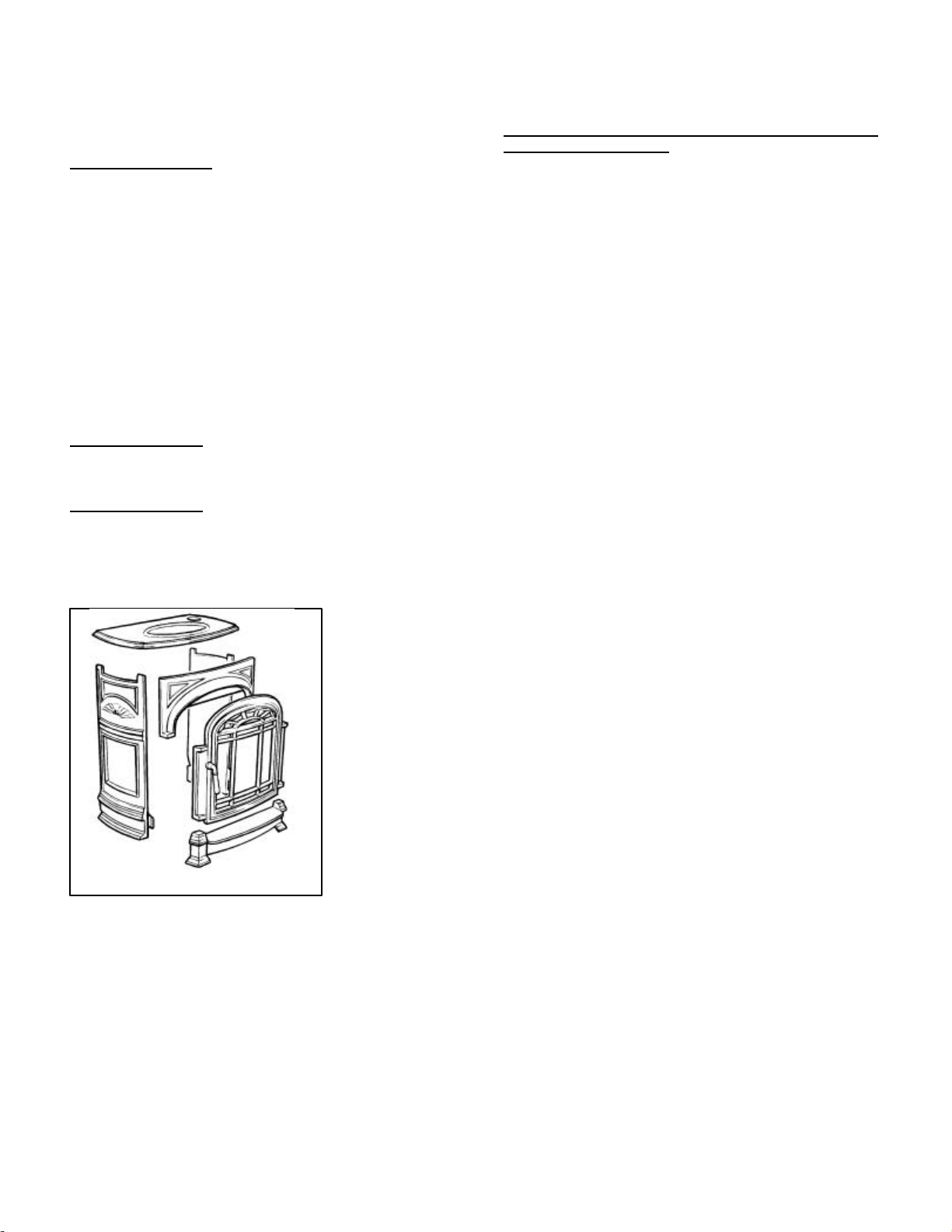
Remove the outer case components from Boxes 2 and 3, identify
each part, and check for transit damage. Note there are two Side
Panels (left and right), a lower ashlip/front feet assembly, an
Arched Lintel component, a Door, and a Top Plate. See exploded
diagram below (Figure 4).
The outer case components comprise:2 Left and right side panels with leveling feet.
1 Ashlip/front feet assembly
1 Arched lintel assembly
1 Door assembly
1 Top plate
Identify the two Side Panels. Take the left panel and observe the
leveling feet. The leveling feet are precision-machined to a high
finish to avoid scratching the hearth.
Offer up the panel to the vertical plane of the fireplace back panel
and observe that the panel sits level on the hearth leaving no
discernible vertical gap against the fireplace. Adjust the leveling
feet to eliminate any such gap.
Place to one side. Similarly adjust the right hand panel for level.
Place to one side.
Fig. 4 Outer case components
6
 Loading...