

Valor Portrait President FS Stove 531CSB Installation Manual
INSTALLATION MANUAL
Portrait
President FS Stove 531CSB
Approved for use with Valor heater model 530 only
Not compatible with 530INI/IPI insert engines
!
DANGER
HOT GLASS WILL
CAUSE BURNS.
DO NOT TOUCH GLASS
UNTIL COOLED.
INSTALLER
Leave this manual
with the appliance.
CONSUMER
Retain this manual for
future reference.
NEVER ALLOW CHILDREN
TO TOUCH GLASS.
A barrier designed to reduce the risk of burns from the hot
viewing glass is provided with this appliance and shall be
installed for the protection of children and other at-risk
individuals.
Note: This kit must be installed or serviced by a qualifi ed
installer, service agency or gas supplier. These instructions
are to be used in conjunction with the main installation
instructions for the above listed heater model.
WARNING: If the information in these instructions is not
followed exactly, a fi re or explosion may result causing
property damage, personal injury or loss of life.
Notes: This kit must be installed
or serviced by a qualifi ed installer,
service agency or gas supplier.
These instructions are to be used
in conjunction with the main
installation instructions for the
above listed heater models.
4001166-10
©2018, Miles Industries Ltd.
1
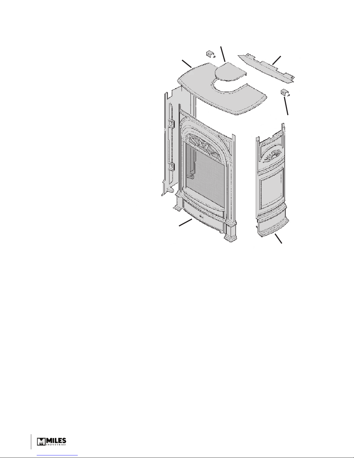
Kit Contents
Front & Sides Pack
(Box 1)
1 Front Casting unit with
Barrier Screen
2 Side Casting units
1 Top Baffl e
2 Stand-off Spacers
1 Pack of Screws & Washers
Top Pack (Box 2)
1 Top Casting
1 Top Infi ll Plate
Top
Casting
Inll Plate
Top Bae
Stand-os
Spacers (2)
Front Casting with
Barrier Screen
Casting Tolerances
Due to the nature of cast iron, dimensional consistency
may vary from one unit to the next and some variation
in surface fi nish and fl atness is to be expected. We
have done our best to control and make allowance for
this; however some variation is inevitable.
Wall & Floor Fixing
The President FS can be installed against a wall or in
the room away from walls. The appliance is designed
to be fi xed to the fl oor. The appliance can additionally
or alternatively be fi xed to a rear wall. The fi xing
positions are shown in fi gure below. The appliance is
approved for installation directly on wood fl ooring. If the
appliance is installed directly on carpeting, vinyl tile or
other combustible material other than wood fl ooring, it
must be installed on a metal or wood panel extending
the full width and depth of the appliance.
Side Casting
Floor Requirements
The 530 heater is approved for installation directly
on any combustible material other than soft fl ooring
material such as carpet or vinyl.
Mantel Requirements
The President FS may be installed with a combustible
mantel provided clearances are maintained as
indicated in the Dimensions and Clearances. Be
aware that although safe, some combustible materials
and fi nishes at the listed clearances may, over time,
discolor, warp, or show cracks. Care should be taken
when choosing materials—consult your fi replace
dealer.
2
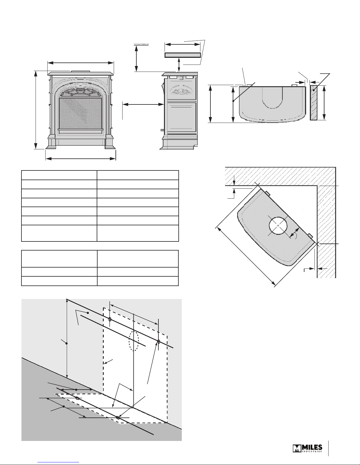
Dimensions & Clearances
Ceiling
36”
24-1/2” (620 mm)
28” (710 mm)
24-1/2” (620 mm)
(914 mm)
min.
36” (914 mm)
min. to
combustibles
Mantel Depth “A” Min. Clearance “B”
Up to 7” 4”
Above 7” up to 8” 5”
Above 8” up to 9” 7”
Above 9” up to 10” 8”
Above 10” up to 12” 9”
More than 12”
Mantel Leg Projection
“D”
9” +extra 1” for every 1”
depth above 12”
Min. Clearance from
Appliance Side “E”
Up to 8” 0”
More than 8” 6”
A
Mantel
B
See table
14-1/2” (368 mm)
1-1/4”
(32 mm)
min. from
casting Top
to wall
Allow
more
space as
necessary
for venting
components
Spacers for
combustible
walls (1-1/4” thick)
13-1/4” (336 mm)
28” (711 mm) min.
E
3-3/4”
(95 mm)
(32 mm)
min. from
casting Top
1-1/4”
to wall
Mantel leg
- see
table
D
WALL
3-3/4” (95 mm)
25-1/2”
(648 mm)
from upper
fixing points to
center of rear
vent pipe
Appliance
outline
7-1/2”
(190 mm)
Center line
of appliance
9-7/8”
(250 mm)
FLOOR
16” (406 mm)
Fixing
points
3
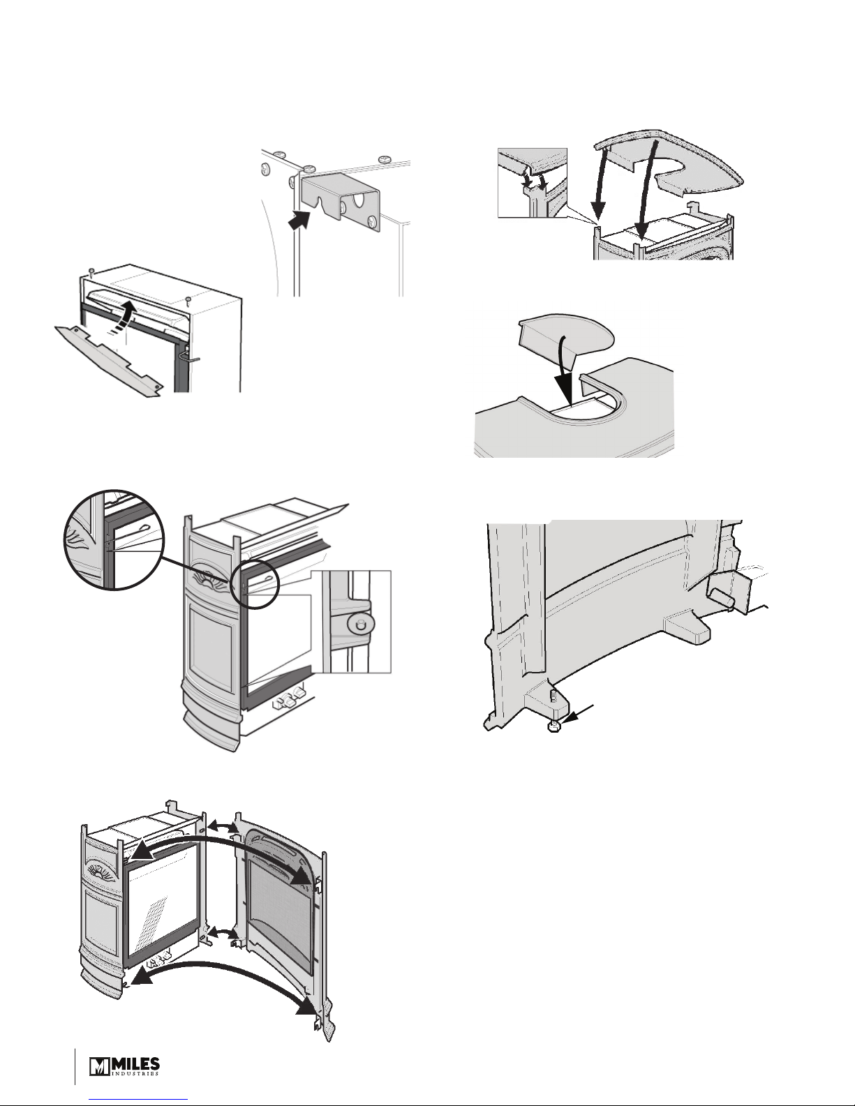
Installation
Ensure that the venting and gas fi tting are completed
and that the ceramics and window are installed before
assembling casting.
1. Attach the stand-off spacers.
They need not be fi tted if the
rear of the appliance is more
than 1-1/4” (32 mm) from
any combustible material.
2. Install the top baffl e using 2
screws supplied.
3. Bolt the left and right side castings in place using
the bolts and washers supplied. Leave the bolts
slightly loose to allow the side castings to move as
necessary when the front casting is hooked on.
5. Fit the top casting making sure that the corners
locate as shown.
Note: The rear edge of the top casting should be
fl ush with the rear edge of the side castings.
6. Fit the top infi ll casting (if rear vent connection).
7. If necessary, the appliance can be leveled by the
adjustment bolts at the back of the side castings.
Note: Lift the
window lever
handle to bolt
to sides and
then bend the
lever handle
back.
4. Hang the front casting by the hooks at the 4 corners.
Side casting
inside
face
Rear levelling bolt
4
 Loading...