

Valor PORTRAIT 575LFK Installation Instructions Manual
PORTRAIT
575LFK Lift Freestanding Kit
CSA approved for use with Valor Models 530I Heaters ONLY
Includes installation instructions for 576LCP and 578LF kits
Installation Instructions
INSTALLER
!
A barrier designed to reduce the risk of burns from the hot viewing
glass is provided with this appliance and shall be installed
for the protection of children and other at-risk individuals.
Notes: This kit must be installed or serviced by a qualifi ed
installer, service agency or gas supplier. These instructions are to
be used in conjunction with the main installation instructions
for the above listed heater models.
The application of this kit does not affect the venting
capabilities or method of preparation of the 530 heater as
described in the 530 heater installation manual.
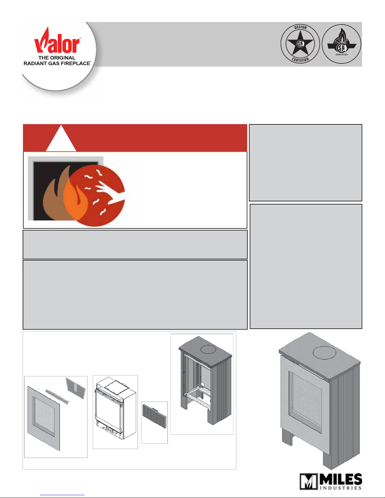
WARNING
HOT GLASS WILL
CAUSE BURNS.
DO NOT TOUCH GLASS
UNTIL COOLED.
NEVER ALLOW CHILDREN
TO TOUCH GLASS.
Leave this manual
with the appliance.
CONSUMER
Retain this manual
for future reference.
To complete the installation
of this kit you need the
following items:
• 530I Portrait Engine
• 575LFK Lift Freestanding
Kit
• 578LF Lift Front
• 576LCP Lower Cover
Panel
(optional)
530I—
Portrait Engine
578LF—Lift Front
Overview
4002695-06
© Copyright Miles Industries Ltd., 2013
(530I, 575LFK, 576LCP and 578LF sold separately)
576LCP—
Lower Cover
Panel
575LFK—Lift Freestanding Kit
(back panel comes with 578 kit)
Basic Installation Sequence
• Assemble sides of casing, bottom and top front
brackets.
• Assemble bottom brackets to heater.
• Fit heater in casing and bolt in place.
• Assemble rear brackets to heater and fi x to casing.
• Gas fi t and vent heater.
• Hook the rear panel, the top panel and infi ll panel.
• Install fi rebox grille and complete installation of
heater as per heater installation instructions.
• Install bracket and place lower cover panel if used.
• Hook window frame cover and front.
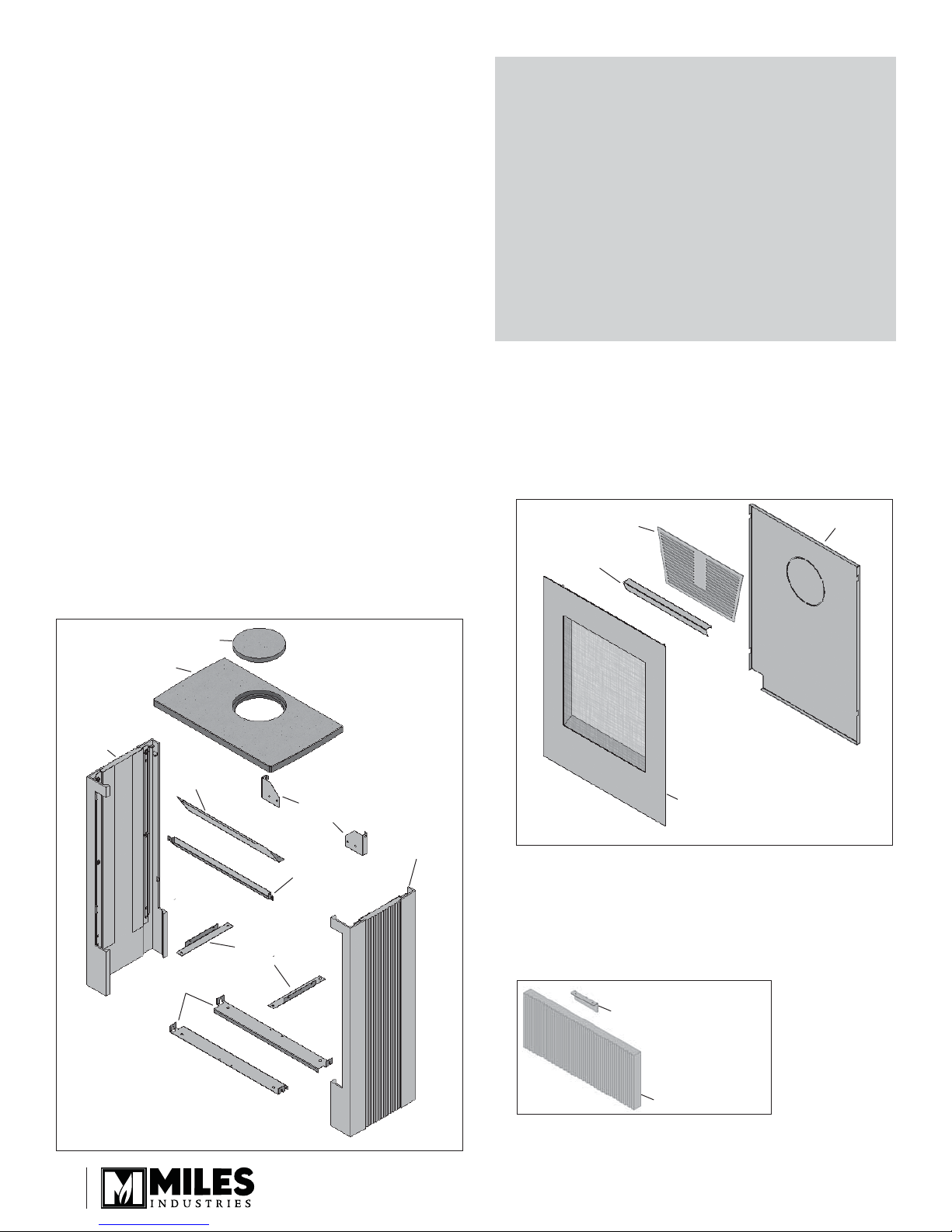
Kits Contents
Tips
• Wear gloves or ensure to manipulate the cast
iron/concrete pieces with clean hands to avoid
any stain.
• Remove the 530 window and all items inside the
appliance before installing to lighten it.
• In steps 4, 5 and 7 in the following instruc-
tions, assemble the parts loosely, just enough
for them to hold together. This will allow you
to fi t all the parts more easily. Then, in step
10, after all the parts are fi tted together and
adjusted, tighten all the screws.
575LFK Lift Freestanding Kit (required)
• Casing left side
• Casing right side
• Top panel
• Top infi ll panel
• Convection baffl e
• Front hanging bracket
• Rear hanging brackets (2)
• Bottom support brackets (2)
• Engine brackets (2)
• Hardware
Top infi ll panel
Top panel
Casing left
hand side
Convection
baffl e
Engine
brackets
Bottom support
brackets
Rear
hanging
brackets
Front
hanging
bracket
Casing right
hand side
578LF Lift Front (required)
• Front trim with screen
• Window frame cover
• Back panel
• Firebox grille
Firebox grille
Window frame cover
Front trim
Back panel
576LCP Lower Cover Panel (optional)
• Lower cover panel
• Support bracket
• Hardware
Support bracket
2
Lower cover panel
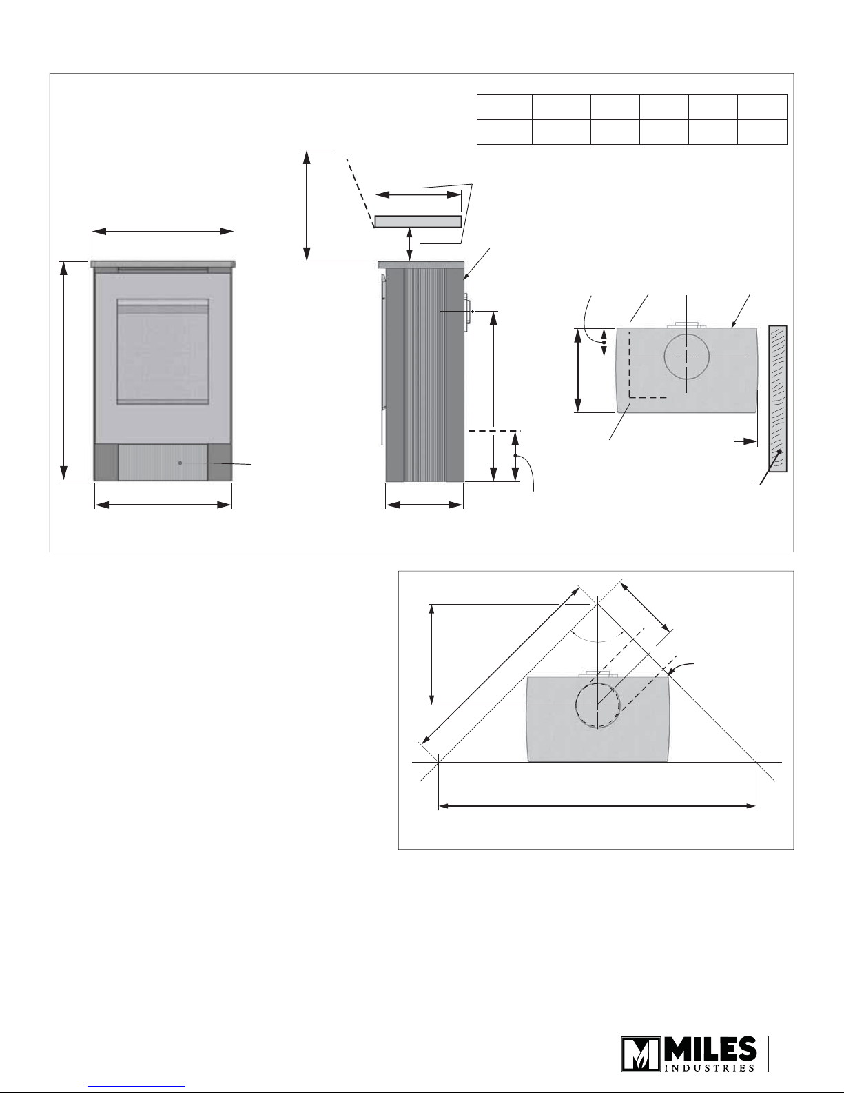
Dimensions & Clearances to Combustibles
Ceiling
Combustible Mantel Clearances
Mantel
Depth ‘A’
Mantel
Height ‘B’2”(51 mm)3”(76 mm)5”(127 mm)7”(178 mm)9”(229 mm)
0–15”
(0–381 mm)
16”
(406 mm)
18”
(457 mm)
20”
(508 mm)
22”
(559 mm)
36”
(914 mm)
576LCP
optional
panel
min.
24-5/8” (625 mm)
37-15/16” (964 mm)
23-11/16” (601.6 mm)
Front View Top ViewRight Side View
Casting Tolerances
Due to the nature of cast iron and concrete, dimensional consistency may vary from one unit to the
next and some variation in surface fi nish and fl at-
ness is to be expected. We have done our best to
control and make allowance for this; however some
variation is inevitable.
Floor Requirements
The 530 heater is approved for installation directly
on any combustible material other than soft fl ooring
material such as carpet or vinyl.
A
Mantel
B
13-5/16”
(338.5 mm)
17-1/4”
Minimum
See table
Zero clearance
29-1/8” (739.7 mm)
x
Gas line access
point 8-1/2” (216 mm)
(438.1 mm)
Minimum 38” (967.3 mm)
4-15/16”
(109.5 mm)
Gas line access
point through
casing
x
14-5/8” (371.5 mm)
Gas line connection
point 3/8” NPT FEMALE
at valve
Minimum
12-1/4”
(311.5 mm)
90°
x
Zero
clearance
3”
(76.2 mm)
min.
Sidewall
Zero clearance
Mobile Home Floor Fixing
The Lift FS must be fi xed to the fl oor through the
fl oor when used in a mobile home.
Mantel Requirements
The Lift FS may be installed with a combustible
mantel provided clearances are maintained as
indicated below. Be aware that although safe,
some combustible materials and fi nishes at the
listed clearances may, over time, discolor, warp,
or show cracks. Care should be taken when
choosing materials—consult your fi replace dealer.
Minimum 53-7/8” (1368.4 mm)
Corner Dimensions
3
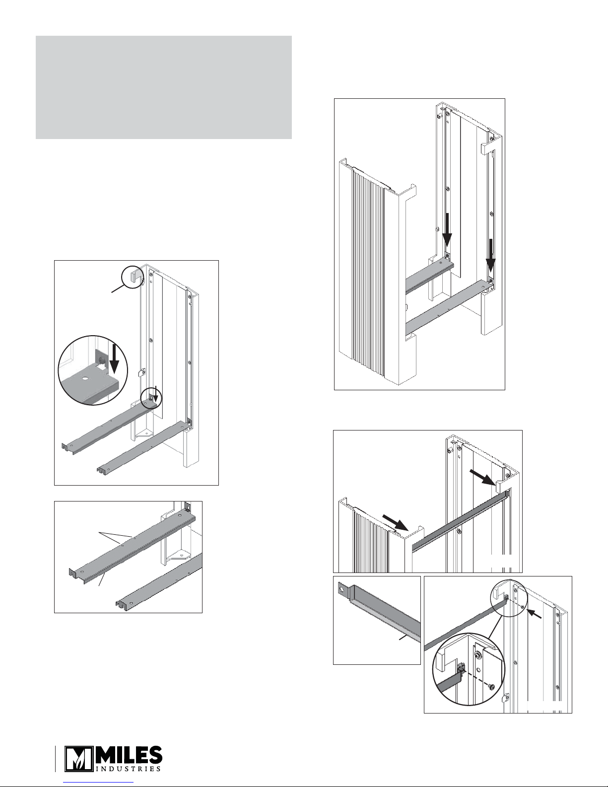
Tip
In steps 4, 5 and 7 in the following instructions,
assemble the parts loosely, just enough for them
to hold together. This will allow you to fi t all the
parts more easily. Then, in step 10, after all the
parts are fi tted together and adjusted, tighten all
the screws.
Installation
1. Identify the front and rear of one cast iron/concrete
side panel. The front of the panel has a protruding
piece at the top.
2. Install the bottom support brackets. Loosen off the
bottom screws and insert the screw heads in the
keyholes of the brackets as shown. Make sure the
brackets are oriented properly. Tighten the screws.
front
3. On the other side panel, loosen off the bottom
screws. Place the fi rst panel at the desired location.
Place the second panel as indicated and attach
the bottom support brackets sliding them over the
screw heads of the panel. Tighten the screws.
Bottom brackets orientation
outer edge with
two holes
inner edge with
downward lip
Front view
4. Loosely fi x the front hanging bracket to the side
panels with one black machine screw on each side.
Rear view
Front view
Top
Rear view
Bottom
Lip goes
to the front
Front view, left side
4
Rear view
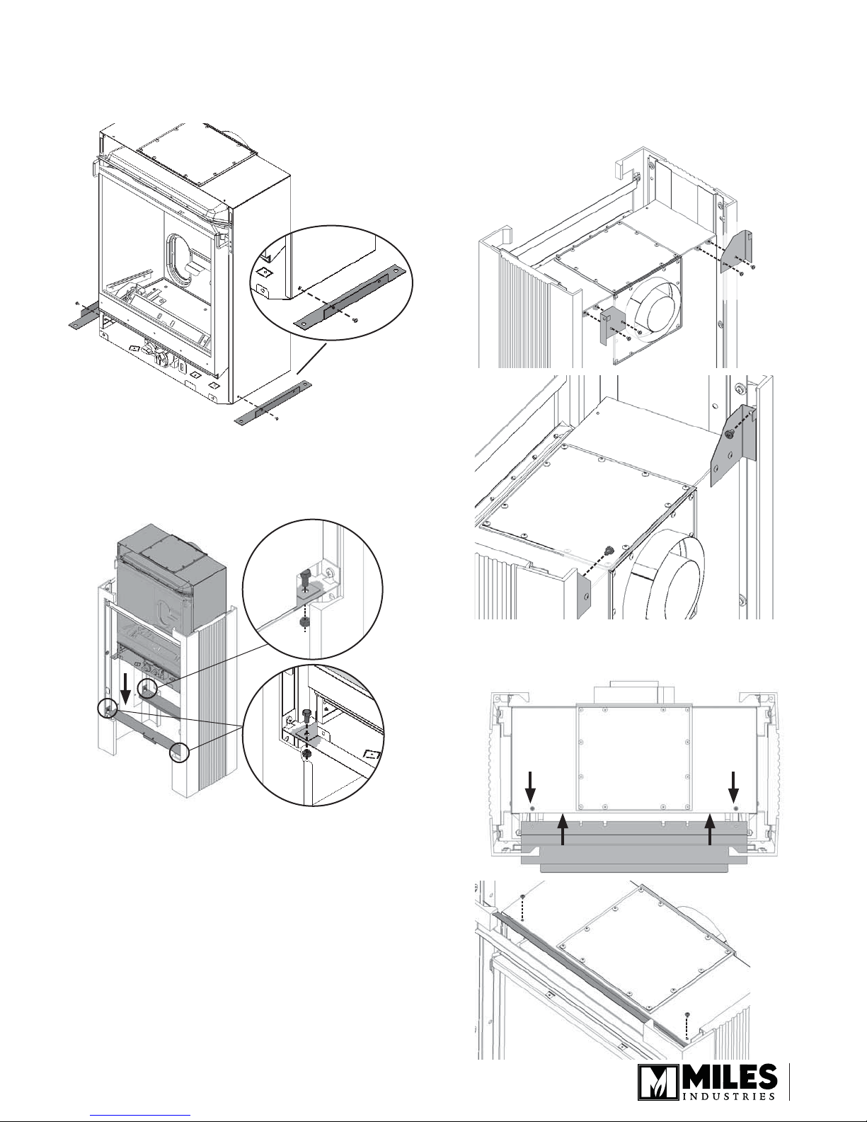
5. Fix the engine brackets to the bottom of the
appliance with one machine screw on each side as
indicated. Either bracket can be used on either side
of the appliance.
6. Slide the appliance into the casing from the top.
Loosely fi x the appliance to the casing with a nut
and bolt on each side at the front and one nut and
bolt at the rear left-hand corner.
7. Remove two screws on each side of the back panel
of the appliance case. Secure the top rear support
brackets to the appliance case using the screws
previously removed. Loosely fi x the appliance to the
casing with one self-tapping screw per side.
8. Slide the convection baffl e under the top panel of
the appliance case. Fix the convection baffl e using
two machine screws provided.
5
 Loading...