

Valor PORTRAIT 539, PORTRAIT 549, PORTRAIT 550 Installation And Owner's Manual
PORTRAIT
Cast Arch Fronts
539, 549 & 550 Series
Approved for use with Valor heater models 530 and 922 only
Installation and Owner’s Manual
!
A barrier designed to reduce the risk of burns from the hot viewing
glass is provided with this appliance and shall be installed
for the protection of children and other at-risk individuals.
Note: This kit must be installed or serviced by a qualifi ed
installer, service agency or gas supplier. These instructions
are to be used in conjunction with the main installation
instructions for the above listed heater model.
WARNING: If the information in these instructions is not
followed exactly, a fi re or explosion may result causing
property damage, personal injury or loss of life.
Valor models 530 and 922 are suitable for installation in a
bedroom or bed sitting room.
WARNING
HOT GLASS WILL
CAUSE BURNS.
DO NOT TOUCH GLASS
UNTIL COOLED.
NEVER ALLOW CHILDREN
TO TOUCH GLASS.
INSTALLER
Leave this manual
with the appliance.
CONSUMER
Retain this manual
for future reference.
Note: Valor models 530 and
922 may be installed in an
aftermarket permanently
located manufactured
(mobile) home, where not
prohibited by local codes.
Valor models 530 and 922
are only for use with the type
of gas indicated on their
rating plate. They are not
convertible for use with other
gases, unless a certifi ed kit is
used.
FOR ARCH INSTALLATION WITH A VALOR 530 ENGINE, READ
INSTRUCTIONS FROM PAGE 2.
FOR ARCH INSTALLATION WITH A VALOR 922 ENGINE, READ
INSTRUCTIONS FROM PAGE 8.
FOR 530 AND 922 ENGINES’ CONFIGURATIONS AND VENTING, REFER
TO MAIN INSTALLATION BOOKLETS SUPPLIED WITH THE ENGINES.
4001125-09
©2013, Miles Industries Ltd.

Kit Contents
539AFB/P Windsor Arch &
550CAP Classic Arch (with plate)
1 Outer cast iron arch (w/plate)
1 Barrier screen
1 Inner cast iron arch
1 Hearth fender, cast iron
2 Side mounting brackets, sheet metal
4 Spacers, sheet metal
1 Top baffl e, sheet metal
1 Top air defl ector, sheet metal
2 Stand-off spacers, sheet metal
(supplied fl at)
2 Insulation Pad
1 Pack of screws
Insulation Blanket
(2 layers)
Top Bae
Air Deector
Model 530 Heater
(sold separately)
Stand-o Spacers (2)
(LH & RH)
Spacers (4)
Side Mounting Brackets (2)
Barrier Screen
549AFB/P Windsor Arch Front
(without plate)
1 Outer cast iron arch
1 Inner cast iron arch fi tted with a Barrier
screen
1 Hearth fender, cast iron
2 Side mounting brackets, sheet metal
4 Spacers, sheet metal
1 Top baffl e, sheet metal
1 Top air defl ector, sheet metal
1 Pack of screws
(Note: The 549 version of
the Windsor Arch Front
[without plate] does not
come with zero clearance
items and is intended for
insert applications only).
Inner Cast Arch
Hearth Fender
Inner Cast Arch
Top Bae
Air Deector
Outer Cast Plate
Model 530 Heater
(sold separately)
Outer Cast Arch
Spacers (4)
Side Mounting Brackets (2)
Barrier Screen
Casting Tolerances
Due to the nature of cast iron, dimensional consistency
may vary from one unit to the next and some variation
in surface fi nish and fl atness is to be expected. We
have done our best to control and make allowance for
this; however some variation is inevitable.
2
Hearth Fender

ARCH FRONT INSTALLATION WITH 530 (539AFB, 539AFP, 549AFB, 549AFP, 550CAP)
Applications
The Valor model 530 heater with the 539 or 550 Cast
Arch Fronts comes ready for installation as a zero
clearance unit into combustible type framing, without
need for a separate zero clearance kit. The 530
installed without the standard zero clearance stand-off
spacers may also be installed into existing solid-fuel
burning fi replaces provided space and local codes
permit.
Hearth Requirements
All installations will require a hearth or fl oor, fl ush with
the bottom of the heater, to support the weight of the
cast iron plate and to ensure the removable hearth
fender rests at the proper height.
A non-combustible hearth is not required in front of this
appliance.
Dimensions & Clearances—539 and 550 Arch
fronts (539 Windsor Arch shown here)
Floor Requirements
The 530 heater is approved for installation directly
on any combustible material other than soft fl ooring
material such as carpet or vinyl.
Mantel Requirements
The Arch Fronts series is designed to install with
combustible mantels provided clearances are
maintained as indicated in the Dimensions and
Clearances, and Framing diagrams below and on
the following page. The 539 and the 550 back plate
may also be installed without a mantel provided listed
clearances are maintained. Be aware that although
safe, some combustible materials and fi nishes at the
listed clearances may, over time, discolor, warp, or
show cracks. Care should be taken when choosing
materials—consult your fi replace dealer.
Min. 36” to
combustible
materials
3
Dimensions & Clearances—
549 Windsor Arch front (without back plate)
‘X’
Mantel
Top or Rear
Outlet
6”
‘Y’
Min. 4”
24”
20”
Wall
Max. 8” deep mantel leg
at edge of arch
Note:
556CLA Adapter
(top or rear outlet)
Required
9”
11-1/2”
2-1/2”
Side Mounting Brackets
34”
31”
Min. 36” to
combustible
materials
4-1/8” 11-1/2”
24-1/2”
Note: The 549 Windsor Arch front is intended for
insert applications only and does not include the
stand-offs and insulation pads required for zero
clearance applications. Most recessed 530 insert
applications will also require a 556CLA Co-linear
Adapter.
(Note that the spacers fi tted to the side brackets
can be removed for a 24” wide insert opening—see
no. 3. in the Installation section on page 5.)
Framing
• The framing dimensions for installation
of the 530 heater with the models 539
or 550 Arch Fronts are shown in the
Framing Diagram.
• A non-combustible hearth is not
necessary in front of the 530 heater.
• The 530 is approved for installation
directly on any combustible material
other than soft fl ooring material such
as carpet or vinyl.
• Any framing construction must be clear
of the standoffs—see Dimensions &
Clearances and Framing Diagram.
• A hearth, fl ush with the bottom of the
heater, will be required to support the
removable hearth fender.
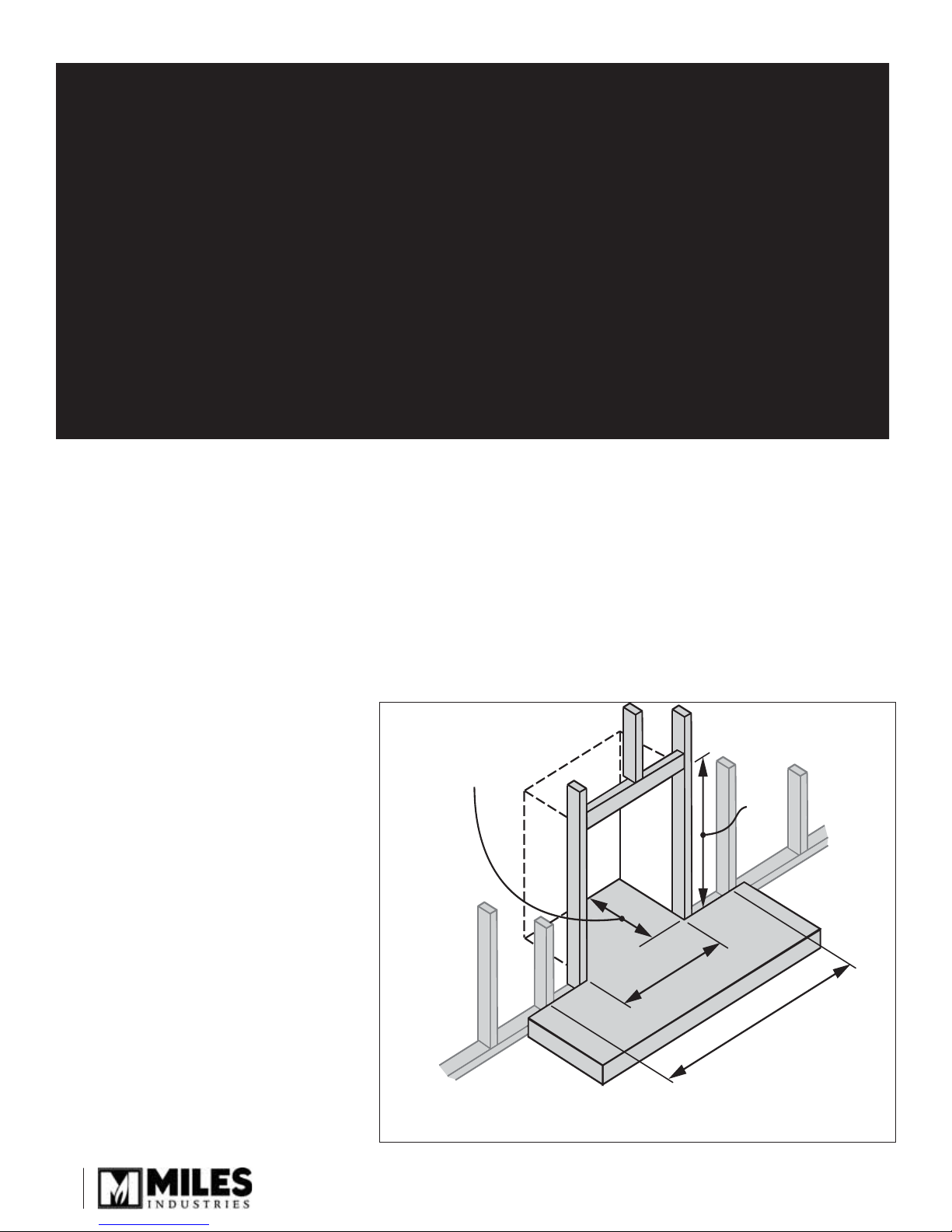
Minimum depth
some installations
may require more
556CLA
Adapter
Required
25-1/4”
13”
26-1/4”
37”
38” center-center
stud spacing
4
Framing Diagram
Recommended for fastening
cast plate to wall
 Loading...