


ATTENTION
Please observe the following precautions to ensure the safe use of this unit.
Handling
Do not get the unit wet. If liquid is spilled on the unit, shut it o immediately.
Do not block any of the ventilation openings.
Keep away from heat sources.
Disconnect the unit during storms to prevent damage.
Operation of this unit within signi cant electromagnetic elds should be avoided.
Connecting the power and
input/output jacks
Always turn OFF the power to the unit and all other equipment before connecting or disconnecting any cables. Also make sure to disconnect all connection cables and the AC adapter before moving the unit.
Cleaning
Clean only with a dry cloth.

Alterations
Do not open the unit.
Do not attempt to service the unit yourself. Opening the chassis for any reason will void the manufacturer’s warranty.
AC Adapter Operation
•Always use a DC9V center negative 500mA AC adapter. Use of an adapter other than that speci ed could damage the unit or cause malfunction and pose a safety hazard.
•Always connect the AC adapter to an AC outlet that supplies the rated voltage required by the adapter.
•UNPLUG THE UNIT DURING LIGHTNING STORMS OR WHEN UNUSED FOR LONG PERIODS OF TIME.
Battery Operation
•Use 4 conventional 1.5V AAA batteries (or nickel metal hydride batteries).
•Carefully read the safety indications on the batteries before use.
•When not using the unit for an extended period, remove the batteries from the unit.
•If battery leakage should occur, thoroughly wipe the battery holder and the battery
terminals to remove battery uid.
•Close the battery holder cover when using the GP-1.
Power Considerations
Since this unit’s power consumption is relatively high, we recommend the use of an AC adapter. If you use batteries, please use alkaline batteries.

Malfunction
If the unit should malfunction, disconnect the AC adapter and turn the power OFF immediately.
Then, disconnect all other connected cables.
Prepare information including the model name, serial number, speci c symptoms related to the malfunction, your name, address and telephone number and contact the store where you bought the unit, or contact VALETON support (info@valeton.net).
Please keep this manual in a convenient place for future reference.

TABLE OF CONTENTS
Overview |
4 |
Introduction |
4 |
Panel Introduction |
6 |
Top Panel |
6 |
Rear Panel |
7 |
Connections |
8 |
Headphone/Practice Configuration |
8 |
Mono Amp Configuration |
9 |
Stereo Amp Configuration |
10 |
Applying Power |
11 |
Applying Batteries |
11 |
1

TABLE OF CONTENTS
Getting Started |
12 |
Modes Explained |
12 |
Navigating Presets |
14 |
Bank Switch |
15 |
Using The Tuner |
16 |
Looper Function |
18 |
Drum Machine |
21 |
Editing Functions |
23 |
Editing Presets |
23 |
Utility |
26 |
2

TABLE OF CONTENTS
Storing Presets |
27 |
Copying A Preset |
27 |
Other Functions |
28 |
External Expression Pedal |
28 |
Factory Reset |
31 |
Pre-Patch-Select |
32 |
Expression Pedal Calibration |
34 |
Effect Types List |
36 |
Presets Patch List |
89 |
Drum Rhythm List |
97 |
Specifications |
105 |
3

OVERVIEW
Introduction
Thank you for choosing a VALETON product!
The GP-1 is a compact, high performance guitar multi-e ects processor. It o ers a potent e ects processing platform and complete feature set, so you can improve your skill and experiment with di erent guitar e ects, all with one simple-to-use, Portable device.
The GP-1 has 100 e ects to choose from and allows you to run 8 e ects simultaneously. It provides a EXP jack that allows you to connect an external Expression Pedal, which can be assigned to the e ect you want to control for real-time e ect changes.
4
100 included factory presets let you jump right in, and 100 user presets allow you to store all your favorite e ects.
The built-in tuner gets your guitar in tune. The built-in drum machine and aux input jack set you up to play along with a drum loop, metronome, or your favorite music.
Whether you're a beginner or an old guitar freak, the GP-1’s got it all to let you have at it!
5

PANEL INTRODUCTION
Top View
1Module Selector:
Switches between function modules. In patch edit mode, this knob selects the module/parameter for operation.
2PARA knob (with enter button):
This knob is used to set the master level or change parameter values. Press the button to switch the type of e ect, begin storing, etc.
1 |
2 |
|
3 |
3 |
LED Display: |
4 |
[+]/[-] Footswitches: |
|
This display shows the patch |
4 |
These footswitches are used for |
|
4 |
numbers, setting values, and |
controlling preset up/down, the |
|
other operation information. |
||
tuner, start/stop drum rhythm, |
||
|
||
|
start/stop/record phrases and |
|
|
other functions. |
6

Rear View
6 OUTPUT Jack: |
7 AUX IN Jack: |
1/4” stereo audio jack, for connecting to a guitar amplifier. You can use a mono cable to output the signal to an amplifier, or use a Y cable to output the signal to two amplifiers.
You can also use a neutral stereo plug to output the signal to headphones.
1/8” (3.5mm) stereo input audio jack. You can connect a CD player, MP3Player or other devices for jamming, practicing, and performance.
5 |
6 |
8 |
9 |
7
10
5INPUT Jack:
1/4” mono audio |
10 |
Battery Holder: |
jack, for connecting |
||
guitar. |
|
For installing batteries (AAA x 4). |
8External Expression Pedal Jack:
1/4” stereo audio jack, for connecting a external expression pedal. You need a stereo cable with1/4” stereo plugs at both ends of the cable for connecting.
9DC 9V Jack:
For power supply, use a 9-volt DC regulated by AC adapter, 500mA (plug polarity is positive on the barrel and negative in the center).
7

CONNECTIONS
Applying Power
1.Before applying power to anything, set your amp to a clean tone.
2.Turn the amp volume all the way down.
3.Connect the power supply to the power jack.
4.Connect the other end of the power supply to an AC outlet.
Applying batteries
1.Insert 4 AAA batteries into the battery holder.
2.Set your amp to a clean tone.
3.Turn the amp volume all the way down.
4.The device will turn on when you plug the guitar cable into the INPUT jack.
5.When not using the unit, please remove the cable from the INPUT jack.
NOTE: When the remaining charge is low, “LBAT” appears on the display and will flash.
8

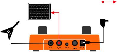
Headphone/Practice Configuration
Headphones
Portable
Music Player
 EXP
EXP
Guitar
Power Supply
9
Mono Amp Configuration
Amp |
Guitar
1/4" Mono Cable
Power Supply
10
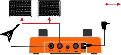
Stereo Amp Configuration
Amp 1 |
Amp 2 |
1/4" Stereo Y Cable
Guitar
Power Supply
11

GETTING STARTED
Modes Explained
The GP-1 has two operation modes: Play Mode and Edit Mode.
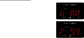
Play Mode
When the GP-1 is powered on and the module selector is turned to “Preset”, the unit will be in Play Mode. The LED screen shows the patch number ( from U-00 to P-99). Play Mode allows you to navigate presets using the PARA knob or footswitches.
When in Play Mode:
Push the PARA button to start/stop the Drum Machine.
12
Edit Mode
Edit Mode allows you to adjust the global Master Level, the Patch Level, select between the di erent e ect modules, edit e ects, and edit the settings for the built-in drums.
NOTE:
·Effect settings changed in Edit Mode will need to be stored to a preset patch.
·The exceptions are the Master Level and drum machine settings, which are global settings and are not stored to
presets.
·Whenever you change a stored preset’s effect settings, the “EDIT” dot below the screen will light up, indicating the effect
settings have been changed from the stored value in the preset.
·See "Editing Presets" (page 23) for more information on storing presets.
13
Navigating Presets
The GP-1 has two preset banks: the User preset bank, which appears in the LED display as U-00 to U-99, and the Factory preset bank, which appears in the LED display as P-00 to P-99. From Play Mode, step on the [+]/[-] footswitches or turn the PARA knob to change presets (Hold down the [+] footswitch to scroll through presets).
NOTE:
·Using pre-patch-select mode (Page 32) , you can jump directly to a patch that is far from the current patch.
·See page 89 for more information on the Presets Patch List section.
14
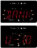
Bank Switch
In play mode, hold down the [-] footswitch for more than 2 seconds until “BANK” appears on the screen.
The tens place digit of the current patch number will begin flash. Step on the [+]/[-] footswitches or rotate the PARA knob to change the preset number.
Press and hold the [-] footswitch to toggle to the ones place digits, and repeat the step above to change the preset number.
Turn the module selector to “Preset”, then hold down the [-] footswitch / press the PARA knob / press both FOOTSWITCHES simultaneously to exit this mode.
NOTE: In this mode, you can still edit the presets.
15
Using The Tuner
Turn the module selector to “Preset”, then press and hold both
FOOTSWITCHES simultaneously.
After “BTU” appears on the screen, release the switches within one second, and the unit will be set to bypass/tuner.
Press and hold both FOOTSWITCHES simultaneously. After “BTU” disappears and “MTU” appears on the screen, release the switches within one second, the unit will be set to the mute/tuner.
NOTE:
· If you continue to press both [+]/[-] foot switches for more than 2 seconds, the looper becomes active (Page 18).
·You can not set the unit to bypass/mute if the module selector isn’t set at PRESET.
16

Turn the PARA knob to set the standard pitch of middle A from 435Hz to 445Hz (Default: 440 Hz) when the unit is in the “BTU/MTU”.
The note name appears on screen. The top 5 LEDs indicate the note of your playing is sharp or flat; the center green LED indicates the note is in tune. The second flashing dot (#) below the screen indicates the sharp note.
Press either FOOTSWITCH to exit the “BTU/MTU”.
17

Looper Function
Turn the module selector to “Preset”, then press and hold both FOOTSWITCHES simultaneously for more than 2 seconds until “LOOP” appears on the screen. Then release the switches to begin using the Looper Function.
After “LOOP” disappears, “EMPT” will appear on the screen, indicating the current loop data.
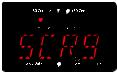
Press the left FOOTSWITCH, and play a guitar phrase. “REC” appears on the display and recording starts. When loop recording is active, the flashing dot indicating “Loop Data” will light up.
18
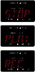
To stop loop playback, press the right footswitch (“STOP” appears on the display).
To start loop playback again, press the left footswitch.
Press the left FOOTSWITCH again to set the loop point, and the recorded phrase will begin playing back. “PLAY” appears on the display.
During loop playback, press the left footswitch (“REC” appears on the display) and begin playing the overdub phrase.
19
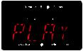
To end overdubbing, press the left footswitch again (“PLAY” appears on the display), and the looped phrase will play with the newly added overdub phrase.
NOTE:
·When in looper mode, use the PARA knob to change the presets, and the effects can still be edited.
·When in looper mode, push the PARA knob to start/stop the drum machine.
·To clear a recorded loop, press and hold the right footswitch for 2 seconds until the display reads “EMPT”, and the
flashing dot of “loop data” will OFF.
·Press and hold both FOOTSWITCHES simultaneously to return to PLAY mode.
20

Drum Machine
Turn the module selector to the DRUM module. The first top LED above the screen will light to indicate the drum pattern.
Press either [+]/[-] footswitch to start playback of the current drum pattern, and press either [+]/[-] footswitch again to stop playback of the drum loop.
Whether the drum loop is playing or stopped, turn the PARA knob to change the drum pattern.
21

Press the PARA knob to move the target parameter to Drum Volume from 00 to 99 (the second top LED above the screen will light up ), then turn the PARA knob to adjust the parameter. Press the PARA knob to move the target parameter to BPM (the
third LED above the screen will light up). Then turn the PARA knob to adjust the parameter. Tempo can be set in a range from 040 to 280.
NOTE:
·When in Play and Looper mode, press the PARA knob to start/stop drum playback.
·When in Edit mode, press the right footswitch to start/stop drum playback.
·When in LOOPER mode, drum rhythm can be recorded in the loop data of the first recording. When recording is finished
and turned to playback, the drum function will become unavailable until the loop data is cleared.
·See page 97 for more information on the Drum Rhythm List section.
22

EDITING FUNCTIONS
EDITING PRESETS
Turn the module selector to Preset, then press either [+]/[-] footswitch to start with an existing preset. Turn the module selector to the e ect module you wish to edit.
This activates Edit mode. The available setting options are listed below:
01. COMP
02. NR
03. DS/AMP
04. EQ
05. CAB
06. MOD
07. DLY
08. REV
NOTE: For more module details, please check Effect Types and Parameters section (Page 36).
23

Turn the module selector to the e ect module and press the left footswitch to bypass or enable an e ect module.
Turn the module selector to the desired e ect module and press the
PARA knob to enable it.
To edit a enabled module in the edit mode, rotate the PARA knob to select an e ect TYPE (the TYPE selected is indicated as the top LED lights up).
Press the PARA knob to select among three parameters of the current e ect ( the A/B/C selected is indicated as the top LED lights up).
Rotate the PARA knob to modify the e ects settings by the current parameter.
24
Anytime a stored value within a preset is changed, the “EDIT” dot below the screen will light up , including the Patch Volume and the EXP target parameters (indicated by the TYPE LED and the B/C LED of the UTIL position).This indicates that you need to store the changes.
If you change presets or cut the power before saving, all edits will be lost. Save the patch to retain your settings.
25
 Loading...