

VAL Avionics AP 100 Installation And Operator's Manual
VAL AVIONICS L TD
AP 100 AUDIO PANEL
Audio Management System
Installation and Operator’s
Manual
Original Issue
October 06
P/N 0720100

Val Avionics Ltd
AP 100 Audio Panel
Installation and Operator’s Manual
Table of Contents
Pg
1 SECTION I - GENERAL INFORMATION .............................................................. 1
1.1 INTRODUCTION .............................................................................................. 1
1.2 SCOPE................................................................................................................ 1
1.3 EQUIPMENT DESCRIPTION .......................................................................... 1
1.4 SPECIFICATIONS............................................................................................. 2
1.5 EQUIPMENT SUPPLIED.................................................................................. 3
1.6 EQUIPMENT REQUIRED BUT NOT SUPPLIED .......................................... 3
1.7 LICENSE REQUIREMENTS............................................................................ 3
2 SECTION II - INSTALLATION................................................................................ 4
2.1 GENERAL INFORMATION............................................................................. 4
2.1.1 Scope........................................................................................................... 4
2.2 UNPACKING AND INSPECTION................................................................... 4
2.3 EQUIPMENT INSTALLATION PROCEDURES ............................................ 4
2.3.1 Cooling Requirements ................................................................................ 4
2.3.2 Mounting Requirements.............................................................................. 5
2.3.3 Wire Harness Fabrication ........................................................................... 5
2.3.4 Audio Panel Installation.............................................................................. 5
2.4 POST INSTALLATION CHECK...................................................................... 6
2.4.1 Operational Check ...................................................................................... 6
2.4.2 Final Inspection........................................................................................... 6
2.5 LIMITATIONS................................................................................................... 7
3 SECTION III - OPERATION..................................................................................... 8
3.1 GENERAL INFORMATION............................................................................. 8
3.1.1 Scope........................................................................................................... 8
3.1.2 Transmit Selection...................................................................................... 8
3.1.3 Audio Selection........................................................................................... 8
4 SECTION IV - WARRANTY AND SERVICE....................................................... 10
4.1 WARRANTY ................................................................................................... 10
4.2 SERVICE.......................................................................................................... 11
5 Appendix A – INSTALLATION DRAWINGS AND CONNECTOR
LAYOUT
.................................................................................................................. 12
6 Appendix B – WIRING DIAGRAMS...................................................................... 13
7 Appendix C – INSTRUCTIONS FOR CONTINUED AIRWORTHINESS ........... 15
7.1 MAINTENANCE INSTRUCTIONS ............................................................... 15
Table of Figures
Figure 1 Uint Controls....................................................................................................... 8
Figure 2 Unit Controls....................................................................................................... 9
Figure 3 Physical Dimensions ......................................................................................... 12
Figure 4 Panel Cut Out .................................................................................................... 12
P/N 0720100 i
Original Issue October 06

Val Avionics Ltd
AP 100 Audio Panel
Installation and Operator’s Manual
Table of Tables
Pg
Table 1 Specifications......................................................................................................... 2
Table 2 Equipment Supplied.............................................................................................. 3
Table 3 Equipment Not Supplied....................................................................................... 3
Revision History
Rev. Date Description of change
IR September 2006 Initial Release
P/N 0720100 ii
Original Issue October 06

Val Avionics Ltd
AP 100 Audio Panel
Installation and Operator’s Manual
1 SECTION I - GENERAL INFORMATION
1.1 INTRODUCTION
Ease of installation and simple operation make the AP 100 Audio Management System
the communication solution for a wide variety of aircraft panels, from the Homebuilt
through heavy twins. The AP 100 satisfies the need for convenience of a fully
functioning quality Audio panel that can be counted on to provide years of reliable
service.
Before installing and /or using your new AP 100 Audio Panel please read this manual
completely. This will ensure proper installation and familiarize you with all of the
features your new audio panel has to offer.
1.2 SCOPE
This manual will provide detailed information about the installation and operation of the
AP 100 Audio Panel. It will also provide equipment limitation information and
instructions for continued airworthiness.
1.3 EQUIPMENT DESCRIPTION
The AP 100 has been designed for simplicity. It is straight forward to install and operate.
Using state of the art technology Val Avionics has created an Audio Panel that will
provide the pilot with simple unencumbered control of the various audio sources
commonly found in today’s civil aircraft.
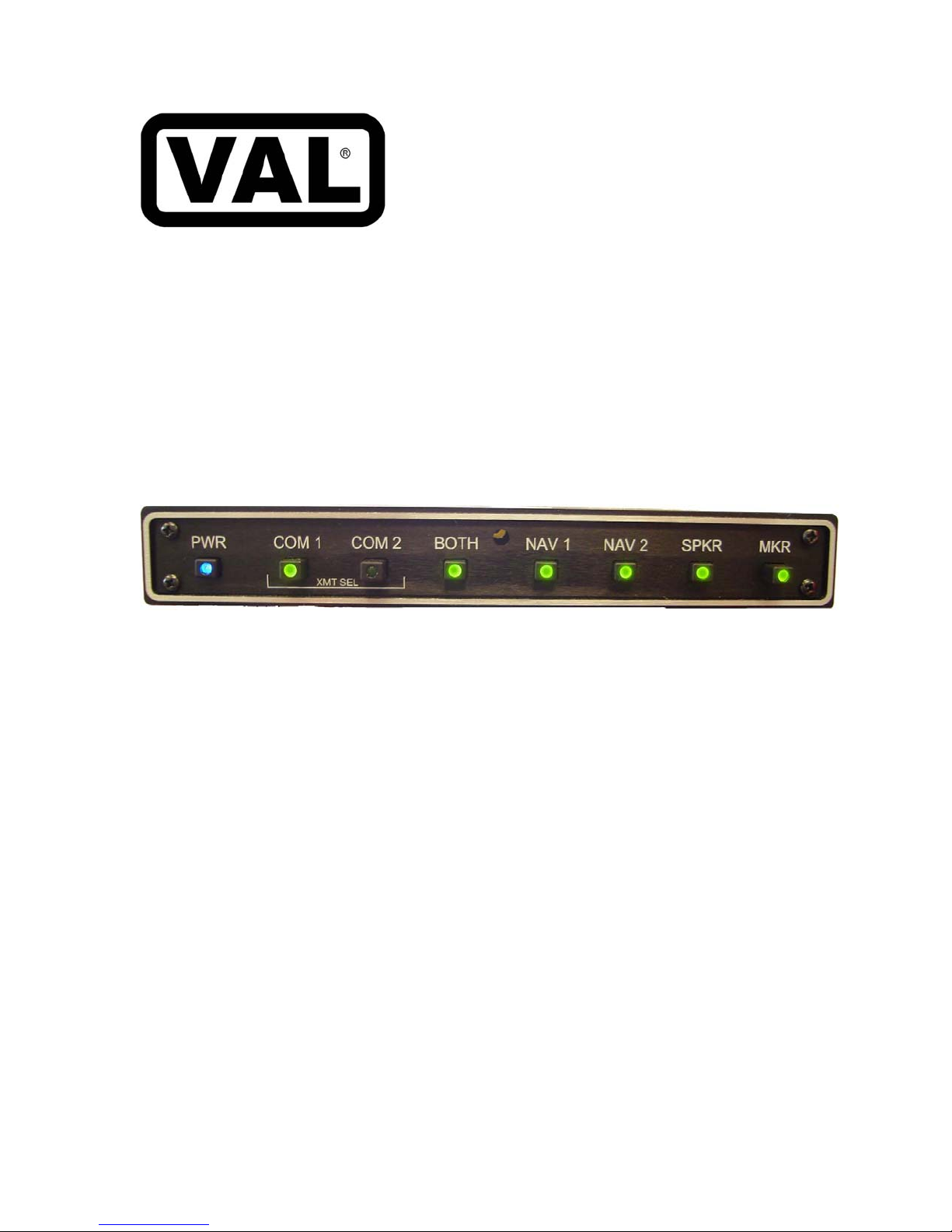
The COM 1 / COM 2 XMT SEL switches make it easy to select a transceiver for
transmitting and receiving radio communications. The selected transceiver is indicated by
an illuminated LED. This LED flashes while the transmit key is depressed. Received
audio from the selected transceiver is automatically switched to the headphones.
Received audio from both COM 1 and COM 2 can be routed to the headphones as desired
by activating the BOTH switch. When both audios are selected an LED annunciation will
illuminate.
NAV 1 and NAV 2 audios can be switched to the headphone using the NAV 1 and NAV
2 selector switching. These selections are also indicated by LED annunciation. All of the
selected audios can be switched to the cabin speaker with the SPKR select switch. An
LED annunciation will indicate this selection.
P/N 0720100 Page 1
Original Issue December 06

Val Avionics Ltd
AP 100 Audio Panel
Installation and Operator’s Manual
Muting for the external marker beacon receiver audio is provided by the MKR switch. A
steady LED annunciator for the MKR switch indicates that marker beacon received
audio, if present, will be heard in the headphones and over the cabin speaker if the SPKR
switch is selected. The pilot may mute the marker audio by depressing the MKR select
switch. Doing so will mute the incoming marker audio for approximately 20 seconds.
While the marker audio is muted the MKR LED annunciator will flash.
Four un-switched audio inputs are provided at the rear connector for such audio inputs as
DME, ADF, Auto Pilot alerts or any other audio source which would commonly be
routed to the aircraft headphone and cabin speaker systems.
A Fail-safe feature has been incorporated into the design of the AP 100 that will
automatically connect the pilot’s headphones and microphone to the aircrafts COM 1
radio in the event that power is removed from the audio Panel or if the unit is powered
down.
1.4 SPECIFICATIONS
Table 1 Specifications
DIMENSIONS
Hight 1.0 in. (2.54 cm)
Width 6.34 in (16.10 cm)
Depth 5.83 in (14.81 cm) behind the panel
WEIGHT 16 oz
ELECTRICAL
Voltage input range 12.5-18 Vdc
Current 500 mA max
Audio input impedance 600 ohms
Input isolation Better than 80db
AUDIO OUTPUT
Headphones 50 mW Continuous RMS power into 150
ohms
Cabin speaker 2.5 W Continuous RMS power into 4 ohms
AUDIO INPUTS
Switched COM 1, COM 2, NAV 1, NAV 2, MKR
Un-switched 4 (examples ADF, DME, Autopilot Alerts)
P/N 0720100 Page 2
Original Issue December 06

Val Avionics Ltd
AP 100 Audio Panel
Installation and Operator’s Manual
1.5 EQUIPMENT SUPPLIED
Table 2 Equipment Supplied
QTY DESCRIPTION PART NUMBER
1 AP 100 AUDIO PANEL 0800100
1 MOUNTING TRAY 0511002
1 INSTALLATION KIT 0650100
1.6 EQUIPMENT REQUIRED BUT NOT SUPPLIED
Table 3 Equipment Not Supplied
QTY DESCRIPTION PART NUMBER
1 Interconnect Wire Harness VPN 0751005 or field
fabricated
1 Microphone Jacks Switchcraft P/N S12B (Ref
VPN 550018)
1 Headphone Jacks Switchcraft P/N 11 (Ref
VPN 550017)
1 Circuit Breaker 2 amp Potter & Brumsfield W58-2
(Ref VPN 0331005)
1 Aircraft Cabin Speaker Ref aircraft parts manual for
specific part number
1 Contact Crimping Tool w/
Positioning Tool
AMP P/N 601966-1
AMP P/N 601699-5
1.7 LICENSE REQUIREMENTS
None
P/N 0720100 Page 3
Original Issue December 06
 Loading...