

Page 1

VAL AVIONICS LIMITED
Communications Excellence
Revision
AWOS 2000
INSTALLATION/OPERATION MANUAL
Page 2

V A L A V I O N I C S , L I M I T E D
AWOS 2000
Val Avionics, Ltd.
3280 25th Street SE
P O Box 13025
Salem, Oregon 97309
Page 3

Table of Contents
GENERAL INFORMATION ....... 2
SPECIFICATIONS..................... 3
OPERATION ............................. 4
INSTALLATION......................... 5
Page 4

A W O S 2 0 0 0 T R A N S M I T T E R
General Information
The AWOS 2000 is a 760-channel communication transmitter and is designed to
provide one way communication within the frequency range of 118.000 MHz to
136.975 MHz in 25 kHz increments.
The AWOS 2000-communication transmitter was designed to conform to FAA
Advisory Circular 150/5220-16B for use as a ground based VHF transmitter for
Automated Weather Observing Systems (AWOS).
The AWOS 2000 communication transmitter has Federal Communications
Commission (FCC) type acceptance filed under FCC ID: EZN5PRAWOS2000
The AWOS 2000 consists of two major sections: Main Board and Transmitter Board.
INSTALLATION/OPERATION MANUAL
REVISION 1 - JUNE 2010 PAGE 2222
Page 5

A W O S 2 0 0 0 T R A N S M I T T E R
Specifications
Physical Dimensions: Width: 5.9 inches
Height: 2.3 inches
Length: 7.45 inches
Weight 3.0 Lbs.
Voltage: 13.75 ± 0.5 Vdc
Current: Standby 250 mA; Transmit 2.0 A
Frequency Range: 118.000 to 136.975 MHz
Channel Spacing 25 kHz
Frequency Stability: . 001%
Spurious Emissions Greater Than 80 dB down from carrier
Modulation Adjustable (50 to 90% Typical)
Temperature Range -30 to +55 Degrees Celsius
Transmit Power: 2.5 watts
Emission 6K 00A3E
Duty Cycle 100%
Design All Solid State. Printed Circuit Board & Point to Point Wiring.
Mounting Rigid Mounting, No Shock Mounting Required.
FCC ID EZN5PRAWOS2000
Unit Part Number 0800202
INSTALLATION/OPERATION MANUAL
REVISION 1 - JUNE 2010 PAGE 3333
Page 6

A W O S 2 0 0 0 T R A N S M I T T E R
Operation
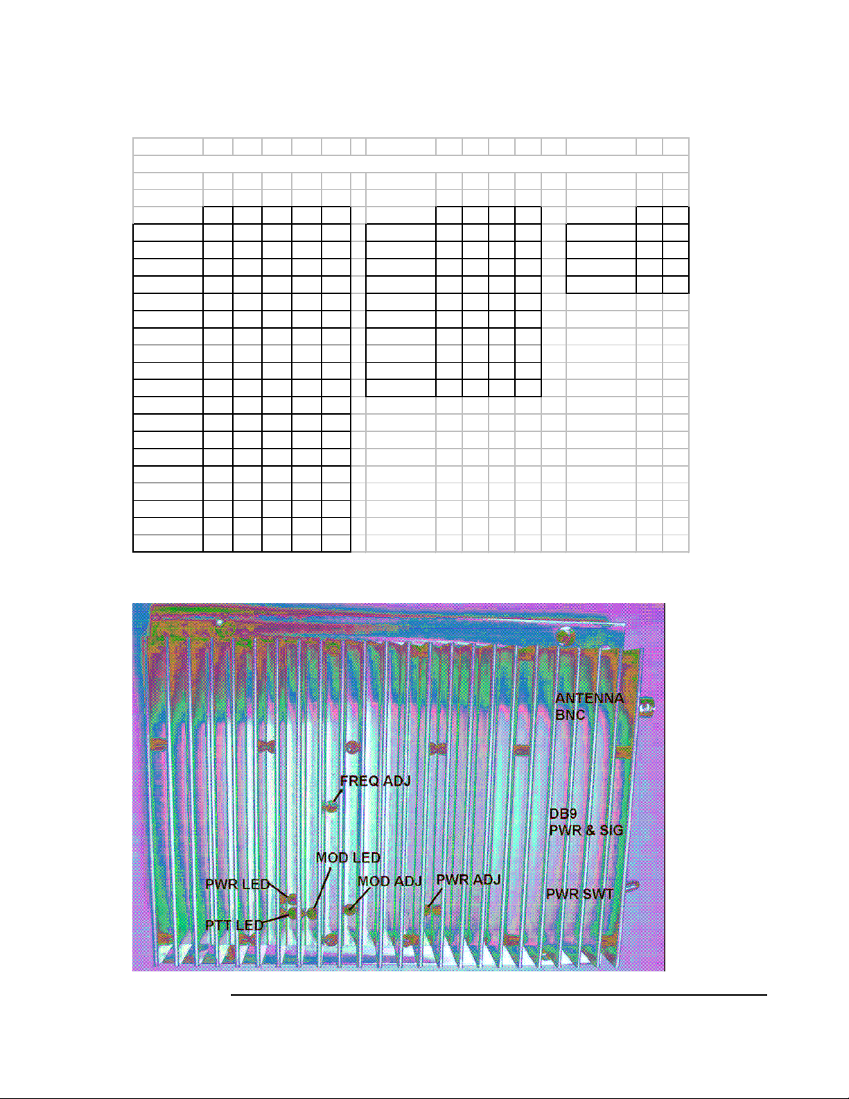
CONTROLS:
ON/OFF SWITCH turns on and off the main power to the unit.
INDICATOR LIGHT Illuminates when the unit is powered up.
DB-9 CONNECTOR connections for power, ground, mic audio, and transmit key are
made at this connector.
ANTENNA JACK connects to a broad band VHF 50 Ohm loaded antenna
FREQUENCY CALIBRATION capacitor C427 can be adjusted to center the output
frequency.
MODULATION ADJUST potentiometer R423 can be adjusted to vary the
modulation level.
POWER ADJUST potentiometer R419 can be adjusted to vary the output power.
DIPSWITHCES M0-M4 selects the whole MHz frequency (see table, page 8)
DIPSWITCHES K2-K5 selects the tenth MHz frequency (see table, page 8)
DIPSWITCHES K0-K1 selects the 25 kHz spacing (see table, page 8)
INSTALLATION/OPERATION MANUAL
REVISION 1 - JUNE 2010 PAGE 4444
Page 7

A W O S 2 0 0 0 T R A N S M I T T E R
INSTALLATION
This section contains suggestions and factors to consider before installing the AWOS
2000 transmitter. Close adherence to these suggestions will assure more satisfactory
performance from the equipment.
The AWOS 2000 installation will conform to standards designated by the customer,
installing agency, and existing conditions as to the unit location and type of installation.
The installing agency will supply and fabricate all external cables for interface to their
system as appropriate. VAL Avionics, Ltd will supply the connectors required.
Unpacking and Inspecting
Unpack the equipment and inspect each item for evidence of damage incurred during
shipment. If a damage claim must be filed, save the shipping container and all packing
materials to substantiate your claim. The claim should be filed with the Transportation
Company as soon as possible. The shipping container and packing material should be
saved in any case in the event that storage or reshipment of the equipment is necessary.
Installation Settings and Adjustments
The AWOS unit should be allowed to operate in the transmit mode for a time period
sufficient to allow the components and temperature to stabilize.
Selecting Frequency. The desired frequency is selected by setting the eleven
switches on DS401 and DS402 located on the bottom of the unit. The operating
frequency is then selected by setting the switches in accordance with the Truth Table
on page 8. Fine tuning the frequency is achieved by adjusting C427. (The AWOS
2000 is set at the factory at 118.9 MHz)
Setting Power Level. Adjust R419 for the proper power setting. (2.5 watts).
Setting Modulation. With a standard audio tone applied at the audio input adjust
R423 to the desired modulation level.
NOTE: FINAL MODULATION AND POWER LEVELS MUST BE
SET WITH THE AWOS 2000 CONNECTED TO SITE
ANTENNA.
INSTALLATION/OPERATION MANUAL
REVISION 1 - JUNE 2010 PAGE 5555
Page 8

A W O S 2 0 0 0 T R A N S M I T T E R
Cooling Requirements
The most important consideration to improved reliability of this equipment is to limit
the maximum operating temperature. While modern designs consume less total energy,
the heat dissipated per unit volume (Watts/cubic inch) remains much the same due to
contemporary high density packaging techniques. While each individual unit may or
may not require forced air cooling, the combined heat generated by several various
units within a typical AWOS cabinet assembly can significantly degrade the reliability
of the AWOS 2000 transmitter if provisions for adequate cooling are not incorporated
in the particular installation.
The AWOS 2000 transmitter is designed to operate within a temperature range of –30
to +55 degrees Celsius. The installing agency will be responsible for providing
mounting and operating environments that do not exceed the operating temperature
range specified.
FAILURE TO PROVIDE THIS TYPE OF INSTALLATION
ENVIRONMENT WILL VOID THE MANUFACTURERS WARRANTY!
INSTALLATION/OPERATION MANUAL
REVISION 1 - JUNE 2010 PAGE 6666
Page 9

A W O S 2 0 0 0 T R A N S M I T T E R
PIN ASSIGNMENT
The pin assignment and function for P401/J401 are as follows:
PIN
TERMINAL
1
2
3
4
5
6
7
8
9
FUNCTION
GROUND (AUDIO RETURN)
POWER INPUT (+13.75 Vdc)
POWER INPUT (+13.75 Vdc)
TRANSMITTER KEY
GROUND
GROUND (KEY RETURN)
GROUND
AUDIO IN
INSTALLATION/OPERATION MANUAL
REVISION 1 - JUNE 2010 PAGE 7777
Page 10
A W O S 2 0 0 0 T R A N S M I T T E R
AWOS 2000 FREQUENCY SELECT CHART
M4 M3 M2 M1 M0 K5 K4 K3 K2 K1 K0
XXX 0 1 0 1 1 XXX
118.
XXX 0 1 1 0 0 XXX
119.
XXX 0 1 1 0 1 XXX
120.
XXX 0 1 1 1 0 XXX
121.
XXX 0 1 1 1 1 XXX
122.
XXX 1 0 0 0 0 XXX
123.
XXX 1 0 0 0 1 XXX
124.
XXX 1 0 0 1 0 XXX
125.
XXX 1 0 0 1 1 XXX
126.
XXX 1 0 1 0 0 XXX
127.
XXX 1 0 1 0 1
128.
XXX 1 0 1 1 0
129.
XXX 1 0 1 1 1
130.
XXX 1 1 0 0 0
131.
XXX 1 1 0 0 1
132.
XXX 1 1 0 1 0
133.
XXX 1 1 0 1 1
134.
XXX 1 1 1 0 0
135.
XXX 1 1 1 0 1
136.
0 1 1 0 XXX.X
.0
0 1 1 1 XXX.X
.1
1 0 0 0 XXX.X
.2
.3
.4
.5
.6
.7
.8
.9
0 0 1 XXX.X
0 1 0
0 1 1
1 0 0
1 0 1
1 1 0
1 1 1
00
25
50
75
0 0
0 1
1 0
1 1
INSTALLATION/OPERATION MANUAL
REVISION 1 - JUNE 2010 PAGE 8888
 Loading...