Vaisala K-PATENTS Instruction Manual

IM-EN-MI-C

Instruction Manual

Multichannel User Interface

MI

PUBLISHED BY

Vaisala Oyj

Vanha Nurmijärventie 21, FI-01670 Vantaa, Finland P.O. Box 26, FI-00421 Helsinki, Finland

+358 9 8949 1

Visit our Internet pages at www.vaisala.com.

General safety considerations

Always power off the Multichannel user interface MI before accessing the modules behind the display. Vaisala recommends the installation of an external power switch.

Warning! Ifthisdeviceisusedagainstmanufacturer’sinstructions,usersafetymaybe compromised.

Warranty

For standard warranty terms and conditions, see www.vaisala.com/warranty.

Please observe that any such warranty may not be valid in case of damage due to normalwearandtear,exceptionaloperatingconditions,negligenthandlingorinstallation, orunauthorizedmodifications. PleaseseetheapplicablesupplycontractorConditions of Sale for details of the warranty for each product.

Technical support

Contact Vaisala technical support at helpdesk@vaisala.com. Provide at least the following supporting information:

Product name, model, and serial number

Name and location of the installation site

Nameandcontactinformationofatechnicalpersonwhocanprovidefurtherinformation of the problem

For more information, see www.vaisala.com/support.

Document/Revision No. IM-EN-MI/C

Effective: June 5, 2020

Disposal

When wishing to dispose of an obsolete instrument or any parts of an instrument, please observe local and national regulations and requirements for the disposal of electrical and electronic equipment.

Symbols and terms used in this manual:

This indicates a warning. It provides safety precaution information needed to avoid injury while operating the refractometer system.

Thisindicatesthatsomethingis importantfortheoperationoftherefractometer system.

Note. Notes contain additional information and hints.

This product manual is delivered to the end user with a Vaisala K-PATENTS® product. Information in this manual is subject to change without notice. When the manual is changed, a revised copy is published at http://www.kpatents.com/

© Copyright Vaisala 2020. All rights reserved.

Document/Revision No. IM-EN-MI/C

Effective: June 5, 2020

Table of contents

1

Description . . . . . . . . . . . . . . . . . . . . . . . . . . . . . . . . . . . . . . . . . . . . . . . . . . . .

1

2

Mounting . . . . . . . . . . . . . . . . . . . . . . . . . . . . . . . . . . . . . . . . . . . . . . . . . . . . . .

2

3

Connections . . . . . . . . . . . . . . . . . . . . . . . . . . . . . . . . . . . . . . . . . . . . . . . . . . . .

8


3.1

Connecting the power cable . . . . . . . . . . . . . . . . . . . . . . . . . . . . . . . .

9


3.1.1

Power terminals for AC power . . . . . . . . . . . . . . . . . . . . . . . . . . . . .

9


3.1.2

Power terminals for DC power . . . . . . . . . . . . . . . . . . . . . . . . . . . .

10


3.1.3

External mains switch . . . . . . . . . . . . . . . . . . . . . . . . . . . . . . . . . . .

10


3.2

Refractometer cable connections . . . . . . . . . . . . . . . . . . . . . . . . . . .

12


3.3

Ethernet cable connection . . . . . . . . . . . . . . . . . . . . . . . . . . . . . . . . .

12


3.4

Module cards . . . . . . . . . . . . . . . . . . . . . . . . . . . . . . . . . . . . . . . . . . .

12


3.5

Connections for external control of Recipe app . . . . . . . . . . . . . . . .

13

4

Use . .

. . . . . . . . . . . . . . . . . . . . . . . . . . . . . . . . . . . . . . . . . . . . . . . . . . . . . . . .

15


4.1

Main display . . . . . . . . . . . . . . . . . . . . . . . . . . . . . . . . . . . . . . . . . . . .

15


4.2

Activating and removing apps . . . . . . . . . . . . . . . . . . . . . . . . . . . . . .

19


4.3

Managing users and passwords . . . . . . . . . . . . . . . . . . . . . . . . . . . . .

23


4.4

System log . . . . . . . . . . . . . . . . . . . . . . . . . . . . . . . . . . . . . . . . . . . . . .

25


4.5

Ethernet connections . . . . . . . . . . . . . . . . . . . . . . . . . . . . . . . . . . . . .

25


4.5.1

MI ethernet connection . . . . . . . . . . . . . . . . . . . . . . . . . . . . . . . . .

25


4.5.2

Refractometer connection . . . . . . . . . . . . . . . . . . . . . . . . . . . . . . .

27


4.5.3

Modbus/TCP connection . . . . . . . . . . . . . . . . . . . . . . . . . . . . . . . .

27


4.5.4

Ethernet/IP connection . . . . . . . . . . . . . . . . . . . . . . . . . . . . . . . . . .

28

5

Apps .

. . . . . . . . . . . . . . . . . . . . . . . . . . . . . . . . . . . . . . . . . . . . . . . . . . . . . . . .

31


5.1

Shared functionality . . . . . . . . . . . . . . . . . . . . . . . . . . . . . . . . . . . . . .

31


5.1.1

Application trend . . . . . . . . . . . . . . . . . . . . . . . . . . . . . . . . . . . . . .

31


5.1.2

Application log . . . . . . . . . . . . . . . . . . . . . . . . . . . . . . . . . . . . . . . .

33


5.2

Refractometer app . . . . . . . . . . . . . . . . . . . . . . . . . . . . . . . . . . . . . . .

35


5.2.1

Diagnostics display . . . . . . . . . . . . . . . . . . . . . . . . . . . . . . . . . . . . .

36


5.2.2

Viewing and adjusting parameters . . . . . . . . . . . . . . . . . . . . . . . . .

37


5.2.3

Refractometer verification . . . . . . . . . . . . . . . . . . . . . . . . . . . . . . .

40


5.2.4

Collecting field sample points . . . . . . . . . . . . . . . . . . . . . . . . . . . . .

42


5.3

Recipe app . . . . . . . . . . . . . . . . . . . . . . . . . . . . . . . . . . . . . . . . . . . . .

44


5.3.1

Requirements . . . . . . . . . . . . . . . . . . . . . . . . . . . . . . . . . . . . . . . .

44


5.3.2

Activating Recipe app . . . . . . . . . . . . . . . . . . . . . . . . . . . . . . . . . .

44


5.3.3

Creating a new recipe . . . . . . . . . . . . . . . . . . . . . . . . . . . . . . . . . .

44


5.3.4

Modifying a recipe . . . . . . . . . . . . . . . . . . . . . . . . . . . . . . . . . . . . .

44


5.3.5

Selecting recipe switching mode . . . . . . . . . . . . . . . . . . . . . . . . . .

45


5.3.5.1

Switching recipe manually . . . . . . . . . . . . . . . . . . . . . . . . . . . . .

45


5.3.5.2

Recipe identification numbers for remote control . . . . . . . . . . .

46


5.3.5.3

Switching recipe via General I/O module inputs . . . . . . . . . . . .

47


5.3.5.4

Switching recipe via Modbus/TCP . . . . . . . . . . . . . . . . . . . . . . .

48


5.3.5.5

Switching recipe via Ethernet/IP . . . . . . . . . . . . . . . . . . . . . . . .

48


5.3.6

Using Recipe app to make unit conversions . . . . . . . . . . . . . . . . .

48


5.3.6.1

Creating a recipe for unit conversion . . . . . . . . . . . . . . . . . . . . .

48


5.3.6.2

Displaying several unit conversions simultaneously . . . . . . . . .

49


5.3.7

Configuring mA output for Recipe app . . . . . . . . . . . . . . . . . . . . .

49

6

Module cards . . . . . . . . . . . . . . . . . . . . . . . . . . . . . . . . . . . . . . . . . . . . . . . . .

51


6.1

Installation . . . . . . . . . . . . . . . . . . . . . . . . . . . . . . . . . . . . . . . . . . . .

51


6.2

Configuration . . . . . . . . . . . . . . . . . . . . . . . . . . . . . . . . . . . . . . . . . .

53


6.3

Relay module card PR-50023 . . . . . . . . . . . . . . . . . . . . . . . . . . . . . .

55


6.3.1

Configuring relays . . . . . . . . . . . . . . . . . . . . . . . . . . . . . . . . . . . . .

56


6.3.2

Notification of limit exceeding . . . . . . . . . . . . . . . . . . . . . . . . . . .

58


6.4

mA output module PR-50021 . . . . . . . . . . . . . . . . . . . . . . . . . . . . . .

58


6.4.1

Configuring mA outputs . . . . . . . . . . . . . . . . . . . . . . . . . . . . . . . .

60


6.5

General I/O module PR-50024 . . . . . . . . . . . . . . . . . . . . . . . . . . . . .

61


6.5.1

Connecting inputs/outputs . . . . . . . . . . . . . . . . . . . . . . . . . . . . . .

64


6.5.2

Configuring the general I/O module card . . . . . . . . . . . . . . . . . . .

66


6.5.2.1

Using the general I/O module to trigger prism wash . . . . . . . .

67

7

Prism wash . . . . . . . . . . . . . . . . . . . . . . . . . . . . . . . . . . . . . . . . . . . . . . . . . . .

69


7.1

Configuring prism wash . . . . . . . . . . . . . . . . . . . . . . . . . . . . . . . . . .

69


7.1.1

Wash cycle . . . . . . . . . . . . . . . . . . . . . . . . . . . . . . . . . . . . . . . . . . .

69


7.1.2

Setting prism wash parameters . . . . . . . . . . . . . . . . . . . . . . . . . . .

73

8

Specifications . . . . . . . . . . . . . . . . . . . . . . . . . . . . . . . . . . . . . . . . . . . . . . . . .

75


8.1

Model code . . . . . . . . . . . . . . . . . . . . . . . . . . . . . . . . . . . . . . . . . . . .

77


8.2

Parts . . . . . . . . . . . . . . . . . . . . . . . . . . . . . . . . . . . . . . . . . . . . . . . . . .

78

A EU declaration of conformity . . . . . . . . . . . . . . . . . . . . . . . . . . . . . . . . . . . .

79

B

Software licence . . . . . . . . . . . . . . . . . . . . . . . . . . . . . . . . . . . . . . . . . . . . . . .

81

C

Command selection tree for Refractometer application . . . . . . . . . . . . . . . .

83

D

Command selection tree for settings . . . . . . . . . . . . . . . . . . . . . . . . . . . . . . .

85

© Copyright Vaisala 2020. All rights reserved.

MI instruction manual

Document/Revision No. IM-EN-MI/C

Effective: June 5, 2020

1 Description

1

1 Description

TheMultichanneluserinterfaceMIisanindustrialcomputerdesignedtoaddfunctionality to the PR-43 refractometers. The MI sends and receives data and it can also be used to control the process.

The Multichannel user interface MI connects with up to 4 Vaisala K-PATENTS® PR-43 refractometers. With module cards, it can also be used to add external inputs and outputs (e.g. relays and mA outputs) to your refractometer system.

The MI is operated by the touch-screen display. The stainless steel enclosure gives a good environmental protection and allows also outdoor installations, especially with the included rain cover. The outer door is easy to open by one hand and the handle can be modified for padlock to prevent unauthorized access. The module cards can be reachedbyopeningtheinnerdoor. TheMIhasIP66ratingwhentheouterdoorisopen if the inner door (display panel) is fixed. With outer door closed the rating is IP67.

Figure 1.1 Multichannel user interface MI

© Copyright Vaisala 2020. All rights reserved.

2

MI instruction manual

2 Mounting

The Multichannel user interface MI can be mounted on a wall with wall mounting or on a table with a table stand. The mounting location should be easily accessible. If mounted outdoors, the MI has to be protected from rain and direct sunlight.

Display on eye-level

1-4refractometers

External mains switch

Ethernet


4-20 mA

100-240VAC

Figure 2.1

Mounting guide

Document/Revision No. IM-EN-MI/C

Effective: June 5, 2020

2 Mounting

3


Figure 2.2 Enclosure dimensions

© Copyright Vaisala 2020. All rights reserved.

4


MI instruction manual


for refractometers

Figure 2.3 Enclosure dimensions

Document/Revision No. IM-EN-MI/C

Effective: June 5, 2020

2 Mounting

5

1

325

mm


(12.8

inches)


1

254mm (10 inches)

1

1

1. Bracket screwed to wall by 4 screws.

Screw hole dimensions 325x254mm

Figure 2.4 Mounting the wall bracket

2

4

1


3

1. Four mounting screws

2.

Top screws inserted into top bracket verticalmounting slots

loosely attached

3.

Lower screws slide into bottom bracket horizontal mounting slots

Figure 2.5 Mounting the MI onto the wall bracket

4. Tighten mounting screws x4 width a 19 mm ring spanner

Note: Be careful when mounting, the MI weighs 13 kilos (28.5 lbs).

© Copyright Vaisala 2020. All rights reserved.

6

MI instruction manual

Important: Do not drill mounting holes in the enclosure as that will affect the protection class of the enclosure and damage the electronics.

TheMIisshippedwitharaincover. Vaisalarecommendsthatitisinstalledevenindoors to protect the top of the door from dust and dirt.

1

2


1. Screw out top attaching screws to allow 2. Retighten screws clearance for rain cover to slot in place

Figure 2.6 Mounting the rain cover

The table stand is very simple to mount.

Figure 2.7 Table stand

Document/Revision No. IM-EN-MI/C

Effective: June 5, 2020

2 Mounting

7

The MI door handle can be modified to make space for a padlock to prevent unauthorized access.

Remove handle center cover

Replace center cover once

and remove segment indicated

indicated segment has been

by break-line on the back of cover

removed, making sure the opening


aligns with the channel for the padlock shackle


Figure 2.8 Locking the MI

© Copyright Vaisala 2020. All rights reserved.

8

MI instruction manual

3 Connections


<![if ! IE]>

<![endif]>M


<![if ! IE]>

<![endif]>RS45


<![if ! IE]>

<![endif]>PR-8440 Ethernetcableforinterfaces

<![if ! IE]>

<![endif]>M12-4pin,D-code,M+M Ethernet

<![if ! IE]>

<![endif]>max.90m(295ft)

<![if ! IE]>

<![endif]>PR-8441 Ethernetcableforinterfaces

<![if ! IE]>

<![endif]>M12-4pin,D-code,M+RS45 Ethernet

<![if ! IE]>

<![endif]>max.90m(295ft)

<![if ! IE]>

<![endif]>mAcable

<![if ! IE]>

<![endif]>max.200m(656ft)

<![if ! IE]>

<![endif]>MultiChannelUserInterface,MI 1xM12-4pin,D-code,F(ExternalEthernet) 4xM12-8pin,A-code,F(System)

<![if ! IE]>

<![endif]>M

<![if ! IE]>

<![endif]>M

<![if ! IE]>

<![endif]>100-240VACor24VDC

<![if ! IE]>

<![endif]>M

<![if ! IE]>

<![endif]>Refractometer + MI

<![if ! IE]>

<![endif]>PR-43REFRACTOMETER M-12-8pin,Dcode,M non-Ex

<![if ! IE]>

<![endif]>PR-8430 Platform4cable M12-8pin,A-code,F+M Ethernet,mA,24V

<![if ! IE]>

<![endif]>max.90m(295ft)


<![if ! IE]>

<![endif]>F


Figure 3.1 Multichannel user interface connections

Document/Revision No. IM-EN-MI/C

Effective: June 5, 2020

3 Connections

9

3.1 Connecting the power cable

Warning! Make sure there is no power in your cable. Then open the enclosure and the inner door. You need a TX25 screwdriver to open the inner door retaining screws.

1

3

2

1.Push door gently

2.Lift handle 45 deg up

3.Open the door

Figure 3.2 Opening the enclosure

Remove inner door retaining screws

and open inner door

Figure 3.3 Opening the inner door

Unscrewoneofthecableglandsandpushthepowercablethrough. Connectthepower cable to the power terminals at lower right of the motherboard (see below). Screw on the cable gland. Close the inner door and turn power on.

3.1.1 Power terminals for AC power

TheprimaryACpowerisconnectedtoaseparateterminalstrip1/2/3inthelowerrighthand corner of the motherboard. The three terminals are marked 1.L, 2.N and 3 (protectiveearth). Thepowerterminal3/ isdirectlyconnectedtotheexposedmetal partsoftheMI.Wiringtotheterminalsshallbe1.5mm2 minimum. Theprotectivefuse in the building system shall comply with the local requirements.

© Copyright Vaisala 2020. All rights reserved.

10

MI instruction manual

1.L 2.N 3

Yellow-green

Blue

Brown

Figure 3.4 AC power terminals on the motherboard

3.1.2 Power terminals for DC power

The DC power is connected to a terminal stripe in the lower right-hand corner of the motherboard. The three terminals are marked 1+, 2- and 3 (protective earth). The powerterminal isdirectlyconnectedtotheexposedmetalpartsoftheMI.The24V DC power to this terminal stripe shall be supplied from a secondary circuit which is double or reinforced insulated from the mains supply within the limits for a limitedenergy circuit (maximum 200 VA/U) according to the IEC 61010-1.

3.1.3 External mains switch

External mains switch

Figure 3.5 Installing external main switch

Document/Revision No. IM-EN-MI/C

Effective: June 5, 2020

Vaisala K-PATENTS Instruction Manual

3 Connections

11

Important: The MI does not have a built-in power switch. The system is always powered when connected to a power source. Vaisala recommends mounting an external mains switch to control the MI’s power supply (Figure 3.5). The external power switch shouldbeeasytoaccess. Itisalsorecommendedtousea10A/230Vcircuitbreakerfor power supply.

<![if ! IE]>

<![endif]>slots.module8hasMIAnyofmodulecards

<![if ! IE]>

<![endif]>anyintoinstalledbecanfreeslot.Therecould cardsmodulemultiplebe inslotsdependingon

<![if ! IE]>

<![endif]>needs.I/Oexternal

<![if ! IE]>

<![endif]>screwGrounding


<![if ! IE]>

<![endif]>-+


<![if ! IE]>

<![endif]>OPTIONALPOWER24V SUPPLYFORMI

<![if ! IE]>

<![endif]>4158


<![if ! IE]>

<![endif]>N


<![if ! IE]>

<![endif]>L


<![if ! IE]>

<![endif]>MI

<![if ! IE]>

<![endif]>SLOT8


<![if ! IE]>

<![endif]>INTERFACE

<![if ! IE]>

<![endif]>SLOT6


<![if ! IE]>

<![endif]>SLOT7

<![if ! IE]>

<![endif]>USER

<![if ! IE]>

<![endif]>4


<![if ! IE]>

<![endif]>SLOT5

<![if ! IE]>

<![endif]>CHANNEL


<![if ! IE]>

<![endif]>3SLOT

<![if ! IE]>

<![endif]>SLOT


PR-50023Relayoutputmodule


<![if ! IE]>

<![endif]>MULTI

PR-50021mAoutputmodule


<![if ! IE]>

<![endif]>SLOT2

PR-50023Relayoutputmodule


<![if ! IE]>

<![endif]>1


PR-50021mAoutputmodule

<![if ! IE]>

<![endif]>SLOT


<![if ! IE]>

<![endif]>4pin,- D-code,M


<![if ! IE]>

<![endif]>4118)


<![if ! IE]>

<![endif]>ETHERNET


<![if ! IE]>

<![endif]>M12


<![if ! IE]>

<![endif]>43-...-UN/AX/IA refractometer Intrinsicrefractometerseefurtherwiringdrawing


<![if ! IE]>

<![endif]>PR- (For


<![if ! IE]>

<![endif]>1...4x


<![if ! IE]>

<![endif]>-60Hz

<![if ! IE]>

<![endif]>Output1

<![if ! IE]>

<![endif]>-

<![if ! IE]>

<![endif]>240VAC/50-

<![if ! IE]>

<![endif]>mA

<![if ! IE]>

<![endif]>24VDC

<![if ! IE]>

<![endif]>SUPPLY

<![if ! IE]>

<![endif]>20mA-

<![if ! IE]>

<![endif]>+

<![if ! IE]>

<![endif]>POWER 100

<![if ! IE]>

<![endif]>...4x4


<![if ! IE]>

<![endif]>1


<![if ! IE]>

<![endif]>N L

<![if ! IE]>

<![endif]>-

<![if ! IE]>

<![endif]>SWITCH PR-10900

<![if ! IE]>

<![endif]>MAIN POWER

<![if ! IE]>

<![endif]>M12 CONNECTORS

<![if ! IE]>

<![endif]>INSTRUMENTS

<![if ! IE]>

<![endif]>PR-8430 SAFETY SWITCH Platform 1...4 x PR-7060 4 cable

<![if ! IE]>

<![endif]>M

<![if ! IE]>

<![endif]>60Hz-

<![if ! IE]>

<![endif]>240VAC/50

<![if ! IE]>

<![endif]>code,D4pin,-

<![if ! IE]>

<![endif]>SUPPLY


<![if ! IE]>

<![endif]>POWER 100


<![if ! IE]>

<![endif]>24VDC

<![if ! IE]>

<![endif]>ETHERNET

<![if ! IE]>

<![endif]>-


<![if ! IE]>

<![endif]>or

<![if ! IE]>

<![endif]>-

<![if ! IE]>

<![endif]>...4x

<![if ! IE]>

<![endif]>M12


<![if ! IE]>

<![endif]>N 1 L

+

<![if ! IE]>

<![endif]>PR-8440 Ethernet cable for interfaces

<![if ! IE]>

<![endif]>SOLENOID VALVE FOR PNEUMATICALLY OPERATED 1...4 xSHUT-OFF VALVE ASSEMBLY: PR-3340-24/110/240

<![if ! IE]>

<![endif]>34 56789

<![if ! IE]>

<![endif]>N L L L

<![if ! IE]>

<![endif]>LN

<![if ! IE]>

<![endif]>12

<![if ! IE]>

<![endif]>L N


Figure 3.6 Multichannel user interface wiring

© Copyright Vaisala 2020. All rights reserved.

12

MI instruction manual

3.2 Refractometer cable connections

The refractometers are connected to the MI with a M12 male-female 8 pins A-coded cable PR-8430, maximum length 90 m. The refractometer connectors are located underneaththeMIenclosureasagroupoffour. Refractometerconnectionscanbemade while the MI is powered. A refractometer can be connected to any of the four connectors.

3.3 Ethernet cable connection

The leftmost connector underneath the MI is for ethernet output. It is for a M12 male

4-pins D-coded cable. The cable can be connected while the MI is powered.

If you wish to connect the MI with e.g. a laptop, you can purchase Interconnecting cable PR-8330 with a M12-4 pin connector in one end and a RJ-45 connector in the other end.

3.4 Module cards

For the installation of the module cards, see Chapter 6 “Module cards”.

Document/Revision No. IM-EN-MI/C

Effective: June 5, 2020

3 Connections

13

3.5 Connections for external control of Recipe app

<![if ! IE]>

<![endif]>24VDCor

<![if ! IE]>

<![endif]>240VAC

<![if ! IE]>

<![endif]>mA-output

<![if ! IE]>

<![endif]>GPIO

<![if ! IE]>

<![endif]>3

<![if ! IE]>

<![endif]>4


<![if ! IE]>

<![endif]>5

<![if ! IE]>

<![endif]>6

<![if ! IE]>

<![endif]>QTY

<![if ! IE]>

<![endif]>1-4

<![if ! IE]>

<![endif]>1-4

<![if ! IE]>

<![endif]>1

<![if ! IE]>

<![endif]>1

<![if ! IE]>

<![endif]>1

<![if ! IE]>

<![endif]>1


<![if ! IE]>

<![endif]>Suppliedby

<![if ! IE]>

<![endif]>Vaisala

<![if ! IE]>

<![endif]>Vaisala

<![if ! IE]>

<![endif]>Vaisala

<![if ! IE]>

<![endif]>Vaisala

<![if ! IE]>

<![endif]>Customer

<![if ! IE]>

<![endif]>Customer


<![if ! IE]>

<![endif]>Partnumber


<![if ! IE]>

<![endif]>PR-8430

<![if ! IE]>

<![endif]>MultichannelUserInterfaceMI

<![if ! IE]>

<![endif]>PR-10900


<![if ! IE]>

<![endif]>1

<![if ! IE]>

<![endif]>2


<![if ! IE]>

<![endif]>Component

<![if ! IE]>

<![endif]>PR-43Refractometer

<![if ! IE]>

<![endif]>Platform4cable

<![if ! IE]>

<![endif]>Mainpowerswitch

<![if ! IE]>

<![endif]>mA-outputcable

<![if ! IE]>

<![endif]>GPIOselectioncable


<![if ! IE]>

<![endif]>Item

<![if ! IE]>

<![endif]>1

<![if ! IE]>

<![endif]>2

<![if ! IE]>

<![endif]>3

<![if ! IE]>

<![endif]>4

<![if ! IE]>

<![endif]>5

<![if ! IE]>

<![endif]>6

Figure 3.7 Recipe app controlled via GPIO (SYS-605)

© Copyright Vaisala 2020. All rights reserved.

14

MI instruction manual


<![if ! IE]>

<![endif]>24VDCor240VAC

<![if ! IE]>

<![endif]>mA-output

<![if ! IE]>

<![endif]>Ethernet


<![if ! IE]>

<![endif]>3


<![if ! IE]>

<![endif]>4


<![if ! IE]>

<![endif]>5 6


<![if ! IE]>

<![endif]>QTY

<![if ! IE]>

<![endif]>1-4

<![if ! IE]>

<![endif]>1-4

<![if ! IE]>

<![endif]>1

<![if ! IE]>

<![endif]>1

<![if ! IE]>

<![endif]>1

<![if ! IE]>

<![endif]>1


<![if ! IE]>

<![endif]>Suppliedby

<![if ! IE]>

<![endif]>Vaisala

<![if ! IE]>

<![endif]>Vaisala

<![if ! IE]>

<![endif]>Vaisala

<![if ! IE]>

<![endif]>Vaisala

<![if ! IE]>

<![endif]>Customer

<![if ! IE]>

<![endif]>Vaisala


<![if ! IE]>

<![endif]>Partnumber


<![if ! IE]>

<![endif]>PR-8430


<![if ! IE]>

<![endif]>PR-10900


<![if ! IE]>

<![endif]>PR-8330

<![if ! IE]>

<![endif]>1

<![if ! IE]>

<![endif]>2

<![if ! IE]>

<![endif]>Component

<![if ! IE]>

<![endif]>PR-43Refractometer

<![if ! IE]>

<![endif]>Platform4cable

<![if ! IE]>

<![endif]>MultichannelUserInterfaceMI

<![if ! IE]>

<![endif]>Mainpowerswitch

<![if ! IE]>

<![endif]>mA-outputcable

<![if ! IE]>

<![endif]>Ethernetcable


<![if ! IE]>

<![endif]>Item

<![if ! IE]>

<![endif]>1

<![if ! IE]>

<![endif]>2

<![if ! IE]>

<![endif]>3

<![if ! IE]>

<![endif]>4

<![if ! IE]>

<![endif]>5

<![if ! IE]>

<![endif]>6

Figure 3.8 Recipe app controlled via Modbus/TCP or Ethernet/IP

Document/Revision No. IM-EN-MI/C

Effective: June 5, 2020

4 Use

15

4 Use

Power up the Multichannel user interface MI. A startup display with a progress bar is shown for approximately one minute, then the Main display appears.

The MI is operated by tapping the touch screen. To get access to the MI touch screen, open the enclosure door.

Note: If you find that the touch screen is difficult to use with fingers, try tapping it with e.g. the blunt end of a pen or use a fingernail instead of the whole fingertip. The screen works even when you are wearing gloves.

4.1 Main display

The main view can show up to four application windows at the same time. You can access measurement data and system settings via the Main display.

Tap to access system settings

Tap for second main view screen

Tap anywhere

in the application window to access measurement

Figure 4.1 Accessing measurement and system settings via Main display

The Main display setup is controlled via Settings > General. Display mode and display languagearechosenindrop-downmenus,tapthelittletriangletoseethewholemenu.

If you only have one application (usually a single refractometer), One maximized will makethemostofthedisplay. Dualverticalallowsyoutoseetwoapplication,Quadrant and One on top shows up to of four applications at the same time. Note: If you have three applications and choose One maximized, you’ll only see one application, but the other two will continue to run in the background.

© Copyright Vaisala 2020. All rights reserved.

16

MI instruction manual

Display

mode

Display language

Figure 4.2 Selecting display mode and display language

Figure 4.3 Setting "One maximized"

Document/Revision No. IM-EN-MI/C

Effective: June 5, 2020

4 Use

17

Figure 4.4 Setting "Dual horizontal"

Figure 4.5 Setting "Quadrant"

© Copyright Vaisala 2020. All rights reserved.

18

MI instruction manual

Figure 4.6 Setting "One on top"

Note: If the MI is left with a different display, e.g. Calibration, it will automatically go back to the Main display after a timeout.

Note: YoucanadjustRefractometerapptoshowconcentrationonly,temperatureonly or both concentration and temperature. To change this setting, tap on the application window(seeFigure4.1)andchoose Calibration(Youmayneedtoenteryourpassword to get access to Calibration display). Then select the preferable display mode.

Document/Revision No. IM-EN-MI/C

Effective: June 5, 2020

4 Use

19

Figure 4.7 Calibration display

4.2 Activating and removing apps

The Main display may be empty even when one or several refractometers are connectedtotheMI.Thismeansthatoneorseveralapplicationsmustbeactivated. Goto Settings > Applications, tap on the empty application slot and select the app type and source for that slot. After choosing settings for the app, tap Done to exit the setup.

© Copyright Vaisala 2020. All rights reserved.

20

MI instruction manual

Figure 4.8 Empty main display in quadrant mode

Figure 4.9 Selecting an empty application slot to activate the app

Document/Revision No. IM-EN-MI/C

Effective: June 5, 2020

4 Use

21

Figure 4.10 Selecting a source to activate the app, here application type Ref is already selected

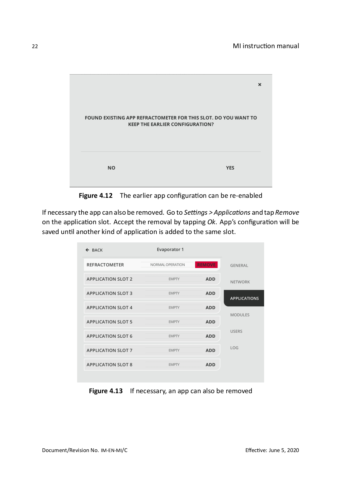
Theemptyapplicationslotmaycontainanearlierappconfiguration. Inthatcaseadia- logwillopenduringappactivationandtheearlierappconfigurationcanbere-enabled.

Figure 4.11 Selecting an empty application slot that contains old Refractometer app configuration

© Copyright Vaisala 2020. All rights reserved.

Loading...
+ 65 hidden pages