

Page 1
QUICK REFERENCE GUIDE
GENERAL
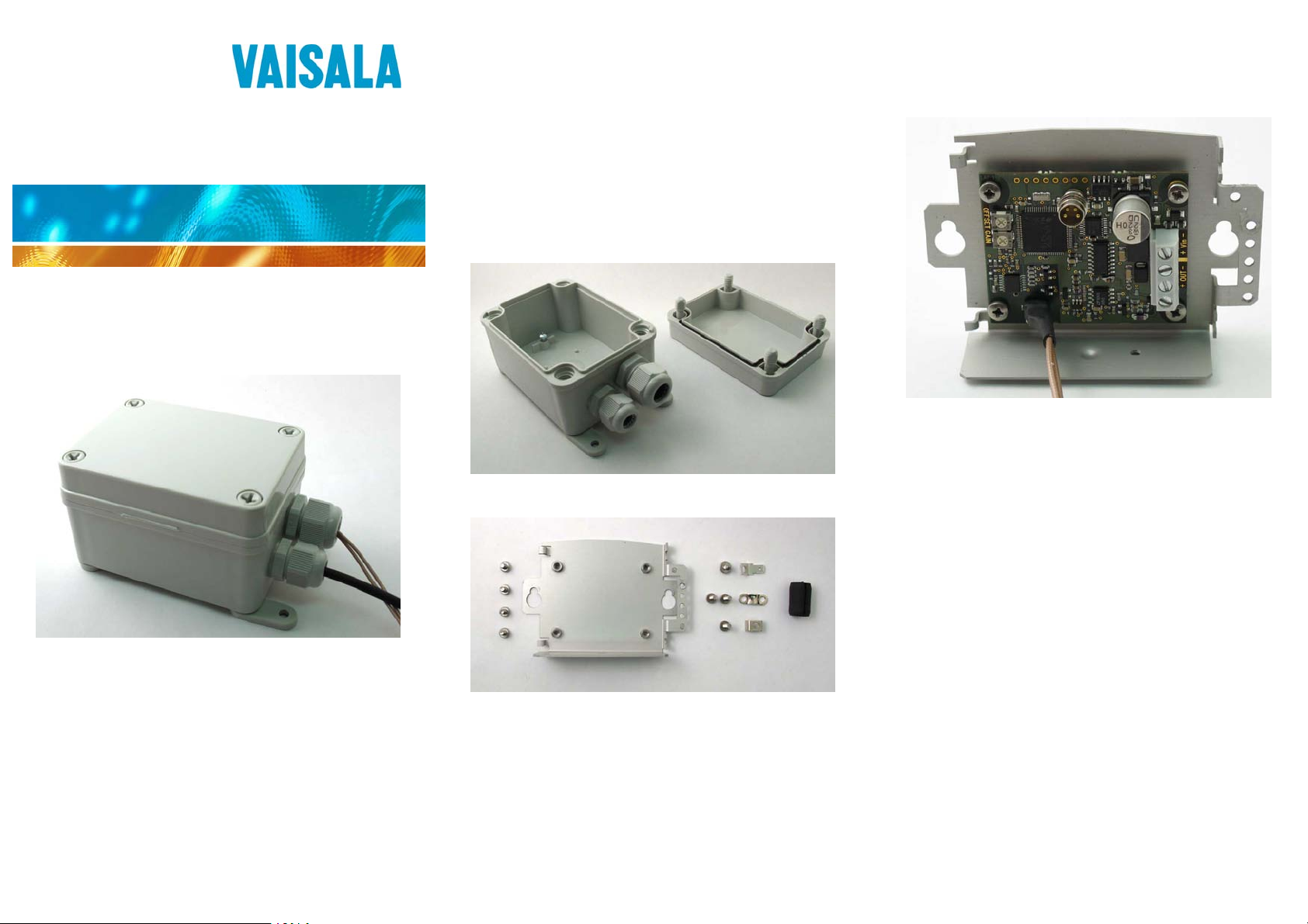
The module housing for HMM100 humidity modules includes
the following items:
- plastic housing with integrated screws on the cover
- metal mounting bracket with screws for the module
- screws and clamps for holding the probe cable and the
power/signal cable
- Abiko connector (4.8mm push-on male terminal) to be used
with unshielded power/signal cables
- two-part rubber plug for sealing the probe cable gland
INSTALLATION
1. Attach the module to the bracket with four screws;
see Figure 3.
Module Housing (IP65) for
Humidity Module HMM100
Figure 3 Module Mounted in the Bracket
– IP65 rated housing for a single
HMM100 module
– For installation in unprotected
environments
© Vaisala 2009. All rights reserved.
*M211078EN*
Figure 1 Housing Opened
Figure 2 Installation Accessories
2. Route the probe cable and your power/signal cable through
the cable glands. The power/signal cable should be 5 ... 10
mm in diameter.
The larger cable gland is meant for the probe cable - push the
probe through it from the inside.
3. Connect the power/signal cable to the screw terminals. Refer
to the HMM100 User's Guide for wiring instructions.
4. Attach the probe cable and the power/signal cable to the right
side of the bracket using the screws and metal clips
(included). See Figure 4 for the suggested placement.
Make sure that the shield of the power/signal cable makes
good contact with the bracket. If your cable is unshielded,
you can provide the earth connection by using a separate
cable and the Abiko connector provided (visible in Figure 4).
Page 2
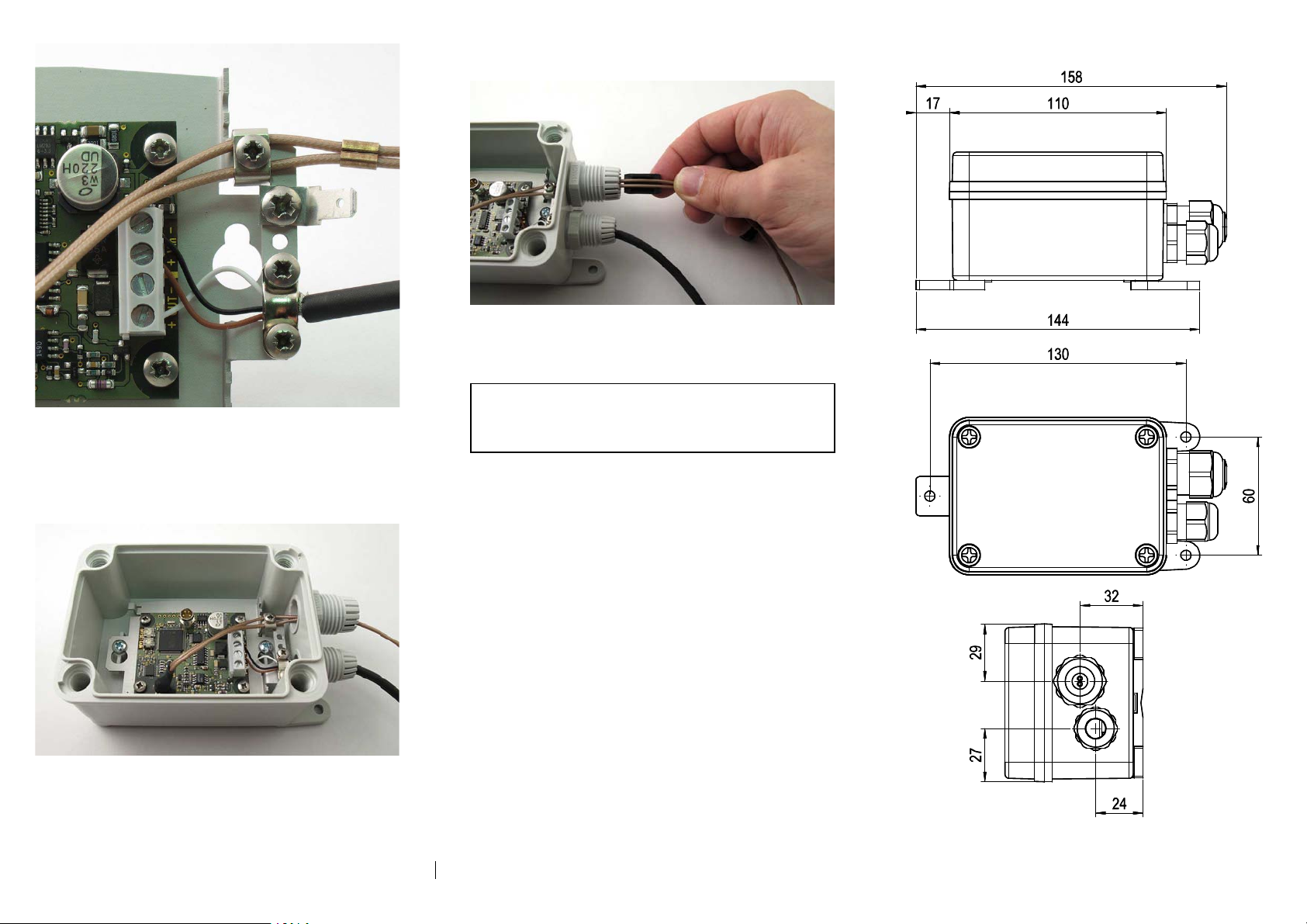
6. Assemble the rubber plug around the probe cable, and push it
DIMENSIONS
into the cable gland. See Figure 6.
Figure 6 Assembling the Probe Cable Plug
7. Tighten both cable glands and close the housing.
Figure 4 Connecting Cables
5. Mount the bracket to the bottom of the housing using the two
large screws that are preinstalled in the bottom of the
housing. The cables should face right toward the cable
glands. See Figure 5.
Figure 5 Bracket Installed and Cables Connected
NOTE When you place the cover on the housing,
match the two raised corners with the
indentations on the cover. Otherwise the
housing will not close tightly.
8. Mount the housing in the desired location. For mounting
dimensions, see Figure 7. The diameter of the screw holes
for mounting the housing is 5.2 mm.
9. Verify the installation: power up the module and check the
output reading.
Figure 7 Module Housing Dimensions
Visit our Internet pages at www.vaisala.com
Ref. M211078EN-A
 Loading...