

Page 1

M211966EN-A
User Guide
Indigo™ 20
2 Digital Transmitter
Indigo 202
Page 2

PUBLISHED BY
Vaisala Oyj
Street address: Vanha Nurmijärventie 21, FI-01670 Vantaa, Finland
Mailing address: P.O. Box 26, FI-00421 Helsinki, Finland
Phone: +358 9 8949 1
Fax: +358 9 8949 2227
Visit our Internet pages at w
© Vaisala Oyj 2017
No part of this manual may be reproduced,
published or publicly displa
or by any means, electronic or mechanical
(including photocopying), nor may its
contents be modified, translated, adapted,
sold or disclosed to a third party without
prior written permission of the copyright
holder. Translated manuals and translated
portions of multilingual documents are
based on the original English versions. In
ambiguous cases, the English versions are
applicable, not the translations.
The contents of this manual are subject to
change without prior notice.
Local rules and regulations may vary and
they shall take precedence over the
information contained in this manual.
Vaisala makes no representations on this
manual’s compliance with the local rules
and regulations applicable at any given
time, and hereby disclaims any and all
responsibilities related thereto.
This manual does not create any legally
binding obligations for Vaisala towards
customers or end users. All legally binding
obligations and agreements are included
ww.vaisala.com.
yed in any form
exclusively in the applicable supply
c
ontract or the General Conditions of Sale
and General Conditions of Service of
Vaisala.
This product contains software developed
by Vaisala or third parties. Use of the
software is governed by license terms and
conditions included in the applicable
supply contract or, in the absence of
separate license terms and conditions, by
the General License Conditions of Vaisala
Group.
This product may contain open source
software (OSS) components. In the event
this product contains OSS components,
then such OSS is governed by the terms
and conditions of the applicable OSS
licenses, and you are bound by the terms
and conditions of such licenses in
connection with your use and distribution
of the OSS in this product. Applicable OSS
licenses are included in the product itself
or provided to you on any other applicable
media, depending on each individual
product and the product items delivered
to you.
Page 3

Table of Contents
Table of Contents
1. About This Document........................................................................................
1.1 Version Information............................................................................................... 5
1.2 Related Manuals..................................................................................................... 5
1.3 Documentation Conventions................................................................................5
1.4 Trademarks............................................................................................................. 6
2. Product Overview................................................................................................7
2.1 Introduction to Indigo™ Transmitters.................................................................. 7
2.2 Indigo 202 Basic Features and Options.............................................................. 8
2.3 Probe Compatibility...............................................................................................8
2.4 Indigo Transmitter Parts........................................................................................9
2.5 Indigo Display....................................................................................................... 10
2.5.1 Graph Display Mode........................................................................................11
2.6 Wireless Configuration Interface Overview.......................................................
3. Installation.............................................................................................................13
3.1 Mounting................................................................................................................13
3.2 Indigo Transmitter Base.......................................................................................14
3.3 Wiring Options......................................................................................................15
3.4 Attaching Probes and Cables..............................................................................16
3.5 Input and Output Specification...........................................................................17
3.6 WLAN and RS-485 Termination OFF/ON DIP Switches.................................. 18
4. Wireless Configuration Interface.................................................................
4.1 Wireless Interface Menus.....................................................................................21
4.2 Connecting to Wireless Configuration Interface............................................. 22
4.2.1 Connecting with a Computer.......................................................................22
4.2.2 Connecting with a Mobile Device................................................................23
4.3 Logging in to Wireless Configuration Interface...............................................24
4.3.1 Changing User Level.....................................................................................25
4.3.2 Changing Administrator Password............................................................. 25
4.3.3 Resetting Administrator Password............................................................. 26
4.4 Measurements View.............................................................................................27
4.5 Status View...........................................................................................................28
4.5.1 Status View: General.....................................................................................28
4.5.2 Status View: Relays.......................................................................................29
4.6 Calibration Menu................................................................................................. 30
4.7 General Settings.................................................................................................. 30
4.7.1 WLAN Settings............................................................................................... 31
4.7.2 User Access Settings (Administrator Password)........................................31
4.7.3 Display Settings.............................................................................................32
4.7.4 Factory Reset.................................................................................................33
4.7.5 License Information...................................................................................... 33
4.8 Modbus Serial Communication Settings.......................................................... 34
4.9 Relay Settings...................................................................................................... 35
4.10 Probe Settings..................................................................................................... 36
12
21
5
5. Modbus.................................................................................................................. 39
5.1 Modbus Overview................................................................................................39
5.1.1 Default Communication Settings............................................................... 40
1
Page 4

Indigo 202 User Guide M211966EN-A
6. Configuring
Relays.............................................................................................41
6.1 Relay Configuration Overview............................................................................41
6.2 Setting Relay Activation Limit Without Hysteresis......................................... 42
6.3 Setting Relay Activation Limit Using Hysteresis..............................................43
6.4 Selecting Relay Error State................................................................................44
7. Calibration and Adjustment..........................................................................45
7.1 Calibration Overview...........................................................................................45
7.1.1 Starting and Closing Calibration Mode...................................................... 46
7.1.2 Restoring Factory Adjustment.................................................................... 47
7.1.3 Calibration PIN Code.....................................................................................47
7.2 Environmental Compensation........................................................................... 48
7.3 Measurements Tab.............................................................................................. 50
7.4 Diagnostics Tab................................................................................................... 50
7.5 Configuration Tab.................................................................................................
51
7.6 GMP252 Example: 2-point CO2 Adjustment.....................................................52
8. Maintenance and Troubleshooting.............................................................55
8.1 Cleaning................................................................................................................55
8.2 Indigo Wireless Connection Troubleshooting..................................................55
8.3 Connecting to Indigo WLAN with iPhone........................................................56
8.3.1 Connection Option 1: Use Without Internet............................................... 57
8.3.2 Connection Option 2: Disable iPhone Auto-Login....................................58
8.4 Display Messages.................................................................................................58
9. Technical Data......................................................................................................61
9.1 Specifications........................................................................................................ 61
.2 Spare Parts and Accessories.............................................................................. 63
9
9.3 Dimensions (in mm)............................................................................................ 64
Appendix A: Modbus Reference.........................................................................
A.1 Function Codes....................................................................................................
65
65
A.1.1 Device Identification Objects...................................................................... 65
A.2 Indigo Status Registers.......................................................................................65
A.2.1 Notification and Error Bits........................................................................... 66
EU Declaration of Conformity..............................................................................
Warranty........................................................................................................................
69
70
Technical Support....................................................................................................... 71
Recycling........................................................................................................................
71
2
Page 5

List of Figures
Figure 1 Probe Connection Options and Wireless Interface
amples (GMP251 Example)...........................................................................7
Ex
Figure 2 Serial Number on Probe Body (GMP251 Example)....................................8
Figure 3 Indigo Transmitter Parts....................................................................................9
Figure 4 Indigo Display with One Parameter ............................................................ 10
Figure 5 Indigo Display with Relays, Three Parameters and WLAN
Notification..........................................................................................................10
Figure 6 Indigo Display in Graph Mode.........................................................................11
Figure 7 Desktop and Mobile Example Views............................................................ 12
Figure 8 Indigo 202 Transmitter Base Main Parts and Screw Positions..............14
Figure 9 Indigo Wiring Options......................................................................................15
Figure 10 Attaching Probes and Cables to Indigo.......................................................16
Figure 11 WLAN and RS-485 DIP Switches on Indigo 202 Circuit Board............ 18
Figure 12 Wireless Configuration Interface, Desktop Browser View......................21
Figure 13 Enabling and Accessing Indigo's Wireless Configuration Interface... 22
Figure 14 Indigo Login View.............................................................................................24
Figure 15 User Level (User/Admin) in Upper Right Corner of Menu View...........25
Figure 16 Measurements View (Desktop Browser)....................................................27
Figure 17 Status View (CO2 Probe Example, Desktop Browser)............................28
Figure 18 Calibration Menu (CO2 Probe Example, Desktop Browser)..................30
Figure 19 Relay Configuration Options (CO2 Probe Example)................................41
Figure 20 Relay Icons on the Optional Display (Relay A Active, Relay
B Not Active)......................................................................................................42
Figure 21 Calibration Menu Main View.......................................................................... 45
Figure 22 Start Calibration Button..................................................................................46
Figure 23 Measurement Selections, CO2 Probe Example.........................................48
Figure 24 Compensation Setpoint and Power-Up Default Selection,
CO2 Probe Example......................................................................................... 49
Figure 25 Measurements Tab, CO2 Probe Example....................................................50
Figure 26 Diagnostics Tab, CO2 Probe Example...........................................................51
Figure 27 Configuration Tab, CO2 Probe Example......................................................52
Figure 28 Additional Steps Needed to Connect Notification..................................56
Figure 29 Indigo Transmitter Dimensions in Millimeters (mm).............................. 64
List of Figures
3
Page 6

Indigo 202 User Guide M211966EN-A
List of Tables
Table 1 Document Versions................................................................................................5
Table 2 Input and Output.................................................................................................. 17
Table 3 Indigo 202 Modbus Registers...........................................................................39
Table 4 Default Modbus Serial Communication Settings........................................40
Table 5 Indigo Transmitter Messages Shown on Display.........................................59
Table 6 Input and Output.................................................................................................. 61
Table 7 General.....................................................................................................................61
Table 8 Standards and Compliance...............................................................................62
Table 9 Wireless Access Point (Module With Internal Chip Antenna).................62
Table 10 Operating and Storage Environment.............................................................62
Table 11 Mechanics.............................................................................................................. 63
Table 12 Spare Parts and Accessories.............................................................................63
Table 13 Supported Function Codes...............................................................................65
Table 14 Device
Table 15 Modbus Status Registers (Read-Only)..........................................................66
Table 16 Bits in Register E001
Identification Objects........................................................................... 65
......................................................................................66
hex
4
Page 7

Chapter 1 – About This Document
1. About This Document
Version Information
1.1
This document provides detailed instructions for using and maintaining Vaisala Indigo™ 202
digital transmitter.
Table 1 Document Versions
Document Code Date Description
M211966EN-A May 2017 First version of the document.
1.2 Related Manuals
Document Code Name
M211967EN Indigo 202 Digital Transmitter Quick Guide
M211877EN Indigo 201 Analog Output Transmitter User Guide
M211876EN Indigo 201 Analog Output Transmitter Quick Guide
M211799EN
M211897EN
Vaisala CARBOCAPâ Carbon Dio
Vaisala CARBOCAPâ Carbon Dio
xide Probe GMP251 User Guide
xide Probe GMP252 User Guide
1.3 Documentation Conventions
WARNING!
carefully at this point, there is a risk of injury or even death.
CAUTION!
carefully at this point, the product could be damaged or important data could be lost.
alerts you to a serious hazard. If you do not read and follow instructions
warns you of a potential hazard. If you do not read and follow instructions
Note highlights important information on using the product.
5
Page 8

Indigo 202 User Guide M211966EN-A
Tip gives information for using the product more eciently.
1.4 Trademarks
Vaisalaâ is a r
Indigo™ is a trademark of Vaisala Oyj.
Chrome™ is a trademark of Google Inc.
Firefoxâ is a registered trademark of Mozilla Foundation.
Microsoftâ, Windowsâ, Internet Explorerâ, and Edge™ are either registered trademarks or
trademarks of Microsoft Corporation in the United States and/or other countries.
Safari™ is a trademark of Apple Inc, registered in the U.S. and other countries.
All other product or company names that may be mentioned in this publication are trade
names, trademarks, or registered trademarks of their respective owners.
egistered trademark of Vaisala Oyj.
6
Page 9

1.35
% | Carbon dioxide
WLAN is activated
Indigo 201
Chapter 2 – Product Overview
2. Product Overview
2.1 Introduction to Indigo™ Transmitters
Figure 1 Probe Connection Options and Wireless Interface Examples (GMP251 Example)
V
aisala Indigo transmitters are a plug-and-play host device platform for Vaisala Indigocompatible probes. Indigo transmitters extend the feature set of connected probes with a
range of additional options for outputs, measurement viewing, status monitoring, and
configuration
interface access.
Depending on the Indigo transmitter model, a display is available as an optional selection or
as a standard feature. In the non-display model, an LED indicator is used for notifications.
Probes can be connected either directly on the transmitter from the probe's connector, or by
using a cable be
tween Indigo and the probe.
The configuration interface of Indigo transmitters is a browser-based wireless UI that
r
equires a mobile device or computer that supports wireless connectivity (IEEE 802.11 b/g/n
WLAN).
The Indigo 202 transmitter is designed for digital output applications. The transmitter's
output options include RS-485 Modbus RTU and 2 programmable relays.
For more information on Indigo transmitter models, see www.vaisala.com/indigo.
More Information
‣
Indigo 202 Basic Features and Options (page 8)
‣
Specifications
(page 61)
7
Page 10
c R
r
Made in Finland, Vaisala Oyj
Vanha Nurmijärventie 21, FI-01670 Vantaa
CO2 PROBE GMP251 A2B0A1N1
Output: 0... 20% CO2 RS485 Vaisala protocol
Input: 12 – 30 V
d
Serial No. N0310004
1
Indigo 202 User Guide M211966EN-A
2.2 Indigo 202 Basic Features and Options
• All Vaisala Indigo-compatible probes can be connected to all Indigo transmitter models
Wireless configuration interface: connect to the scalable browser-based UI of Indigo
•
202 to change probe and transmitter settings, view measurements, and review probe
and transmitter status
• 3.5” TFT LCD color display
• Power supply input 15 ... 30 VDC (20 ... 22 VAC)
• Digital output: RS-485 Modbus RTU
• 2 configurable relays
1 m, 3 m, 5 m and 10 m probe connection cables available as accessories
•
2.3 Probe Compatibility
All Indigo-compatible probes can be used with all Indigo transmitter models. To verify that
y
our probe is compatible with Indigo, check the serial number on the probe body. All probes
intended for use with Indigo manufactured from 2017 onwards (serial numbers starting with
the letter N or latter in alphabetical order) have full compatibility.
Figure 2 Serial Number on Probe Body (GMP251 Example)
1 Probes with a serial number starting with the letter N ha
8
ve been manufactured in 2017.
Page 11

2.4 Indigo Transmitter Parts
2
3
4
6
5
1
Chapter 2 – Product Overview
Figure 3 Indigo Transmitter Parts
1 Display
2 Probe and probe cable connector, locking wheel
3 Wireless (WLAN) configuration
4 Rubber lead-through with strain relief for input/output cable
5 Top cover of the transmitter: display, circuit board and connector pins
6 Transmitter base: input and output wiring (screw terminals), mounting base
CAUTION!
o connect incompatible probes or probe cables can damage the equipment.
t
More Information
‣
Dimensions (in mm) (page 64)
‣
Indigo T
‣
Spare Parts and Accessories (page 63)
ransmitter Base (page 14)
Only use Vaisala Indigo-compatible probes with the transmitter. Attempting
interface activation button
9
Page 12

hPa | Pr
essure
1
2
3
Indigo 202 User Guide M211966EN-A
2.5 Indigo Display
Indigo transmitters use a 3.5” TFT LCD color display for displaying
information, and measurement data.
Figure 4 Indigo Display with One Parameter
notifications, status
Figure 5 Indigo Display with Relays, Three Parameters and WLAN Notification
1 Relay A and relay B status
2 Wireless configuration interface indicator (SSID text and WLAN symbol)
3 Message field for notifications, warnings and errors
10
Page 13

Chapter 2 – Product Overview
The Indigo display can be configured
to show 1-3 measurement parameters. Information
about the transmitter and connected probe (for example, notifications and warnings) is
shown on a message row at the bottom of the display. Relay and wireless access point
activity is also shown on the display.
The parameters shown on the display, display brightness and display mode (numeric or
graph) can be configured with the wireless configuration interface in the Se
ttings > General
menu.
2.5.1 Graph Display Mode
Figure 6 Indigo Display in Graph Mode
ou can set the Indigo display to show the connected probe's measurement data as a graph.
Y
The display mode can be changed in the wireless configuration interface's Se
ttings >
General menu.
More Information
‣
Display Settings (page 32)
11
Page 14

Indigo 202 User Guide M211966EN-A
2.6
Wireless Configuration Interface
Overview
Indigo transmitters are
(requires a mobile device or computer with IEE 802.11 b/g/n WLAN wireless connectivity). In
addition to probe and transmitter configuration and calibration, you can also use the
wireless interface to view measurement data and status information.
configured using a wireless browser-based configuration interface
Figure 7 Desktop and Mobile Example Views
The wireless
configuration rights, not password protected), and personnel that carry out configuration
tasks can log in with an administrative password that allows changing the transmitter and
probe settings.
To use the wireless configuration interface to modify the settings of your Indigo transmitter
and the c
then connect to Indigo with your mobile device or computer. Most major browsers (for
example, Firefox, Chrome, Safari and Internet Explorer) are supported: using the most recent
version is recommended.
More Information
‣
Connecting to Wireless Configuration Interface (page 22)
‣
L
ogging in to Wireless Configuration Interface (page 24)
‣
W
ireless Interface Menus (page 21)
‣
Indigo Wireless Connection Troubleshooting (page 55)
12
configuration interface has two user levels. All users have view-only access (no
onnected probe, you must first enable the transmitter's wireless connection and
Page 15

3. Installation
Mounting
3.1
1. Open the 4 screws on the transmitter cover and pull the cover o the base.
Chapter 3 – Installation
CAUTION!
ansmitter cover o the base in a straight angle. Do not twist or bend.
tr
2. Place the transmitter base on the installation surface and mount it with 3 screws. See
the scr
3. Lead the input/output cable inside the transmitter (see W
wiring through the lead-through on the bottom of the transmitter, test that the strain
relief works with your cable.
ew positions in Figure 1.
To avoid damaging the connector pins of the transmitter, pull the
iring Options). If you are
4. Connect the input/output cable's wiring to the screw terminals (see Indigo Transmitter
Base) and reattach the cover when done.
5. When you have finished wiring and reattached the cover, switch on the power supply
input.
13
Page 16

1 2 4
5
6
3
INDIGO 202
DIGITAL TRANSMITTER
Serial No. SX12345678
24V
d
IN
RS485
A. Relay
B. Relay
Indigo 202 User Guide M211966EN-A
3.2 Indigo Transmitter Base
Figure 8 Indigo 202 Transmitter Base Main Parts and Screw Positions
1 Probe and probe cable connector inside the locking wheel
2 Wireless (WLAN) configuration
3 Wiring from the back: cut open the seal
4 Rubber cable lead-through with strain relief
5 Screw terminals for relays A and B
interface activation button
6 Screw terminals for 24 V power supply input and RS-485 (Modbus) connection
Do not energize the power supply before the wiring has been connected.CAUTION!
14
Page 17
1
2
7 ... 8 mm
Ø
Chapter 3 – Installation
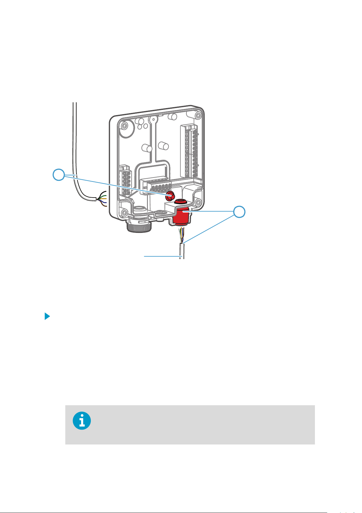
3.3 Wiring Options
You can wire an input/output cable either through the opening on the back of the
ansmitter, or through the rubber lead-through on the bottom of the transmitter.
tr
Figure 9 Indigo Wiring Options
1 Wiring from the back: cut the seal open
2 Wiring through the rubber lead-through on the bottom of the transmitter
1. To wire the input/output cable through the back of the transmitter:
Cut
a.
o as much of the seal as is needed to fit your cable through the opening.
b. Lead the cable through the opening and attach a strain relief as needed.
c. If you wire only through the back, plug or seal the lead-through on the bottom.
2. To wire the input/output cable through the rubber lead-through on the bottom:
a. Push the input/output cable through the lead-through.
b. The lead-through provides strain relief and holds the cable in place. Tightening is not
required.
The recommended cable diameter for wiring through the rubber lead-through is
7 ... 8 mm. If y
intended.
ou use a dierent cable size, test that the strain relief works as
15
Page 18

1
2
3
Indigo 202 User Guide M211966EN-A
3.4 Attaching Probes and Cables
Figure 10 Attaching Probes and Cables to Indigo
1 Insert probes into the probe connector with the orientation mark facing out.
2 Probes are locked in place with the locking wheel. Ne
3 Connect probe cables in the same way as probes: insert the cable in the connector and
hold in place while turning the locking wheel.
1. Insert the probe into the probe connector with the orientation mark on the probe body
acing out.
f
2. Hold the probe in the probe connector and lock it in place by turning the locking wheel
counterclockwise. Do not turn the probe body when attaching, only the locking wheel
on the transmitter.
3. When the transmitter recognizes the connected probe, it shows a notification message
on the displa
y (for example, Probe Connected: GMP251).
ver turn from the probe body.
16
Page 19

3.5 Input and Output Specification
Table 2 Input and Output
Property Specification
Digital output RS-485 Modbus RTU
Relays 2 configurable relays (VAC/VDC)
Device maximum specification (resistive load):
•
Max. switching power 30 W / 37.5 VA
Chapter 3 – Installation
UL-rated maximum
• AC: max. 28 V / 0.5 A
• DC: max. 40 V / 0.24 A
• Up to 30 VDC:
• max. switching current 1 A
• max. switching power 30 W
Power supply input
Maximum current Transmitter and connected probe max. 1 A
Power consumption Transmitter max. 3 W (+ connected probe, varies
Probe connector M12/5 connector for probe or probe cable connection
Cable feed throughs 2 options: rubber lead-through on the bottom of the
Screw terminal wire size
1) Using a power supply with overload protection is recommended for electrical safety.
1)
CAUTION!
oper modification may lead to safety hazards, equipment damage, failure to
Impr
Do not modify the unit or use it in ways not described in the documentation.
Range 15 ... 30 VDC (20 ... 22 VAC)
depending on pr
(V
aisala Indigo-compatible probes)
tr
ansmitter, and opening with a seal at the back of the
transmitter
0.2 mm2 ... 1.5 mm
specification (resistive load):
obe type)
2
perform according to specification, or decreased equipment lifetime.
More Information
‣
Specifications
(page 61)
17
Page 20

WLAN
OFF ON
RS485
TERMINA
TION
OFF ON
1
2
Indigo 202 User Guide M211966EN-A
3.6 WLAN and RS-485 Termination
OFF
If your application requires switching WLAN communication or RS-485 termination o or
on, use the DIP s
/ON DIP Switches
witches on the Indigo circuit board.
Figure 11 WLAN and RS-485 DIP Switches on Indigo 202 Circuit Board
1 WLAN functionality OFF or ON
2 RS-485 termination OFF or ON
To switch WLAN or RS-485 termination OFF or ON with DIP switches:
1. Power o
the transmitter.
18
Page 21
2. Open the transmitter cover.
Chapter 3 – Installation
CAUTION!
ansmitter cover o the base in a straight angle. Do not twist or bend.
tr
To avoid damaging the connector pins of the transmitter, pull the
3. Use a small screwdriver or a similar tool to change the position of the WLAN (1) or
RS-485 t
ermination ON/OFF (2) DIP switches.
4. When done, close the transmitter cover and power on Indigo.
Indigo does not display a notification
when a user attempts to enable it with the wireless connection activation button.
about the WLAN functionality being disabled
19
Page 22

Indigo 202 User Guide M211966EN-A
20
Page 23

1
2
3
4
5
Chapter 4 – Wireless Configuration Interface
Wireless Configuration
4.
Interface
4.1 Wireless Interface Menus
Figure 12 Wireless
1 Measurements: displa
2 Status: contains information about the status of Indigo and the connected probe (for
example, notifications and alarms)
3 Calibration: calibrate and adjust probes using references. Available options (for
example, adjustment points) vary depending on the probe model.
4 Settings: contains options for configuring the connection and display settings, outputs,
relays, probe-specific settings, and general device preferences
• General submenu: device information and general settings, wireless connection
and display settings
5 Main display area for menus and measurement information (desktop browser example)
• Outputs submenu: Modbus serial communication settings
• Relays submenu: settings for controlling relays A and B
• Probe submenu: probe-specific settings such as environmental compensations and
filtering factor
Configuration Interface, Desktop Browser View
ys the measurement data of the connected probe
More Information
‣
C
onnecting to Wireless Configuration Interface (page 22)
21
Page 24

Select WLAN to connect to:
2. Indigo_IDxx
1
3
500
ppm
WLAN on
In
digo 200
2
Carbon dioxide concentration
Indigo 202 User Guide M211966EN-A
4.2 Connecting to Wireless Configuration
Interface
Figure 13 Enabling and Accessing Indigo's Wireless Configuration Interface
1 Wireless connection activation button
2 Wireless connection indicator (WLAN symbol) on the Indigo display
3 Choose Indigo (Indigo_ID[
xx]) from your wireless device's list of available connections
More Information
‣
L
ogging in to Wireless Configuration Interface (page 24)
‣
Indigo W
ireless Connection Troubleshooting (page 55)
4.2.1 Connecting with a Computer
To connect to the Indigo wireless configuration interface with a computer:
Enable wireless connectivity (WLAN) from your computer's settings.
1.
2. Press the wireless connection activation button on the bottom of the Indigo transmitter
until the transmitter notifies about a WLAN connection being active.
Open your computer's wireless connections menu and choose Indigo_ID[xx]
3.
(transmitter-specific SSID) from the list of available connections.
22
Page 25

Chapter 4 – Wireless Configuration Interface
4. When you have established a connection, open your browser. Depending on your
owser and system, you are either directed to the wireless configuration interface's
br
login screen, or you may need to:
a. open a new browser tab or window, or close and restart your browser, if the browser
was already open when you connected to Indigo's access point.
b. acknowledge the connection in a notification prompt before opening your browser
or a new browser tab or window.
The default IP address of the Indigo transmitter is h
trouble opening the wireless configuration interface in your browser, try entering the
IP address in the browser's address bar.
ttp://192.168.1.1/. If you have
5. When the wireless configuration interface opens in your browser, you are prompted to
log in. F
or instructions, see Logging in to Wireless Configuration Interface.
4.2.2 Connecting with a Mobile Device
To connect to the Indigo wireless configuration interface with a mobile device (phone or
t):
table
1. Enable wireless connectivity (WLAN) from your mobile device's settings.
2. Press the wireless connection activation button on the bottom of the Indigo transmitter
until the transmitter notifies about a WLAN connection being active.
Open your device's wireless connections menu and select Indigo_ID[xx] (transmitter-
3.
specific SSID) from the list of available connections.
4. Depending on device settings, the Indigo wireless configuration interface either opens
automatically in your browser, or you may need to:
a. open your browser application manually after connecting to Indigo
b. acknowledge the connection in a wireless network prompt (check your device's
notifications)
before opening your browser.
5. When the wireless configuration interface opens in your browser, you are prompted to
log in. For instructions, see Logging in to Wireless Configuration Interface.
Mor
e Information
‣
Connecting to Indigo WLAN with iPhone (page 56)
23
Page 26

Indigo 202 User Guide M211966EN-A
4.3
Logging in to Wireless Configuration
Interface
Figure 14 Indigo Login View
W
hen you open Indigo's wireless configuration interface in your browser, you are prompted
o log in. There are 2 available user levels:
t
• User: view-only access available for all users. Does not require a password.
• Admin: password-protected access. To change settings, you must log in as admin.
To log in:
1. Enter the user name and password:
a. To log in as user (view-only access, no configuration
User name dropdown. Leave the Password field empty.
b. To log in as admin (required for configuration), select Admin in the User name
dropdown and type the admin password (default: 12345) in the Password field.
2. Select L
opens in the Measurements view.
More Information
‣
Changing User L
‣
Changing Administrator Password (page 25)
‣
Resetting Administrator Password (page 26)
og in after entering the login credentials. The wireless configuration interface
The user level (User or A
Select the user/admin icon in the upper right corner to change the user level.
evel (page 25)
dmin) is shown in the upper right corner of all menu views.
rights), select User from the
24
Page 27

1
Chapter 4 – Wireless Configuration Interface
4.3.1 Changing User Level
A link that allows logging in with a dierent user level is included in the upper right corner of
all menu vie
Figure 15 User Level (User/Admin) in Upper Right Corner of Menu View
ws. The text of the link shows the current user level.
1 Current user level (User/A
dmin): select the text or icon to log in with a dierent user
level
To change between the User and A
dmin user levels:
1. Select the link that shows the current user level (User or Admin) on the upper right
corner of any menu view.
Selecting the link logs you out of the interface, and a new login is required.
2. The login screen opens. Log in as User or A
dmin.
4.3.2 Changing Administrator Password
To change the administrator password:
Connect to the wireless
1.
password: 12345). The user level (User or Admin) can be also changed by selecting the
user level icon in the upper right corner of any menu view.
configuration interface and log in as an administrator (default
2. Open the Settings > General menu.
25
Page 28

Indigo 202 User Guide M211966EN-A
3. In the User A
ccess section, enter the new password (max. 25 characters) in the
Administrator Password field.
4. The new password is saved when you tap or click outside the text field, and is in use at
xt login.
the ne
4.3.3 Resetting Administrator Password
If you have lost or forgotten the admininistrator password and cannot log in, you can reset
the pas
and on.
T
sword back to default (12345). Note that this requires powering the transmitter o
o reset the password:
1. Power o the transmitter.
2.
Keep the wireless connection activation button on the bottom of the transmitter
pressed down.
3. While pressing the wireless connection activation button, power on the transmitter.
Keep the button pressed down until the transmitter start-up is complete (a
measurement is shown on the display).
4. The administrator password has now been reset to the default 12345.
26
Page 29

4.4 Measurements View
Chapter 4 – Wireless Configuration Interface
Figure 16 Measurements View (Desktop Browser)
he Measurements view shows the measurement data from the connected probe in numeric
T
and graph format. When you log in to Indigo, the wireless configuration interface opens in
this vie
w.
27
Page 30

Indigo 202 User Guide M211966EN-A
4.5 Status View
Figure 17 Status View (CO2 Probe Example, Desktop Browser)
The Status view shows the transmitter status, general information about the Indigo
transmitter, and the status of the relays A and B.
4.5.1 Status View: General
The General section of the Status menu shows general information about the transmitter
and the connected probe.
28
Page 31

Chapter 4 – Wireless Configuration Interface
• Indigo S
tatus: shows the current status of the transmitter. Errors and notifications are
displayed here.
• Indigo Serial Number: the transmitter's serial number.
• WLAN Access Point Name: the network name (SSID) of the transmitter. Can be
configured in the Settings menu.
• WLAN MAC Address: unique hardware address of the unit. Cannot be changed.
• Probe: the type and serial number of the probe that is connected to Indigo.
More Information
‣
WLAN Settings (page 31)
4.5.2 Status View: Relays
elay: relay A or relay B
• R
• State: Shows whether the relay is active (set) or not.
• Mode: Relay activation mode (above or below a trigger level, or o)
• Parameter: The parameter that controls the relay
More Information
‣
Relay
Configuration Overview (page 41)
29
Page 32

Indigo 202 User Guide M211966EN-A
4.6
Figure 18 Calibration Menu (CO2 Pr
In the Calibration menu, you can calibrate and adjust the measurement of the probe
connected to the transmitter with the help of references such as calibration gases that have
a known concentration. You can also view the current adjustments and restore the probe's
factory adjustments.
Calibration Menu
obe Example, Desktop Browser)
The available options vary depending on the type of the connected probe (for example,
applicable en
More Information
‣
Calibr
ation Overview (page 45)
vironmental compensations and the number of adjustment points).
4.7 General Settings
The Se
ttings > General menu contains the following configuration options:
• WLAN Settings
• User Access Settings (Administrator Password)
• Display settings
• Factory Reset
• License information
30
Page 33

4.7.1 WLAN Settings
Chapter 4 – Wireless Configuration Interface
• Mode: Selec
t the timeout period for disconnecting the wireless configuration interface,
or remove the timeout from use.
• SSID: The network name that is used to identify the transmitter when connecting to it
(default: Indigo_ID[xx]).
4.7.2 User Access Settings (Administrator Password)
Enter a new administrator password and exit the text entry field.
in the next login.
If you have forgotten or lost the password, you can reset the password back to the default
one (1234
5). For more information, see the login instructions.
The new password is in use
31
Page 34

Indigo 202 User Guide M211966EN-A
4.7.3 Display Settings
General display settings:
• Brigh
• Mode: Selec
tness: set the brightness of the display (20%, 50%, 100% or o).
t whether the display shows the measurement information in graph or
numeric format.
Graph view settings:
• Parameter: Select which parameter's measurement is shown in the graph view.
• Unit: Select the unit that the measurement is shown in (for example, ppmCO2 or %CO2).
32
Page 35

Chapter 4 – Wireless Configuration Interface
ounding: Choose how many decimals of the measurement are shown in the numeric
• R
reading shown alongside the graph view.
• Time Scale: Select the time period shown in the measurement graph (1 minute ... 1
hour).
Numeric view settings:
• Parameter (1-3): Select the measurement parameter or parameters shown in the
numeric view (up to 3 parameters can be shown simultaneously in the numeric view).
• Unit for Parameter (1-3): Select the unit the measurement is shown in (for example,
ppmCO2 or %CO2).
• Rounding for Parameter (1-3): Choose how many decimals of the measurement are
shown in the numeric view.
More Information
‣
Graph Display Mode (page 11)
4.7.4 Factory Reset
Select R
eset to restore the configuration of the transmitter to factory default settings.
4.7.5 License Information
Select the V
iew software licenses link to view information on Indigo 202 software licenses.
33
Page 36

Indigo 202 User Guide M211966EN-A
4.8
Modbus Serial Communication
Settings
The Se
configuration options for Modbus serial communication.
ttings > Outputs menu of the wireless configuration interface contains the
Protocol Modbus protocol options. The Modbus R
Speed Select the baud rate used in Modbus communication: 4800, 9600, 19200,
38400, 57600, or 115200. Default: 19200.
Stop Bits Stop bits used in Modbus communication: 1 or 2. Default: 2.
Parity Select EVEN, ODD or NONE. Default: NONE.
Slave Address Address used when Indigo functions as a Modbus slave (range: 1 ... 247).
Default: 10.
More Information
‣
Modbus Ov
erview (page 39)
TU protocol is in use by default.
34
Page 37

Chapter 4 – Wireless Configuration Interface
4.9
The Se
Both relays have the same configuration options (relay A example shown here).
Relay Settings
ttings > Relay menu contains the configuration options for controlling relays A and B.
Output Mode Select whether the relay is activated when the measurement exceeds the
t trigger, or when the measurement falls below the set trigger. Set to
se
O if the relay is not in use.
Parameter Select which measurement parameter controls the relay.
Unit Select the unit of the measurement parameter (for example, % if the
measurement is in %CO2).
Low Trigger
Level and High
Trigger Level
Error State Choose the behavior of the relay when an error state occurs (switched on
When you use a single setpoint without hysteresis, set the same value for L
Level and High Trigger Level. For instructions on using hysteresis, see Setting Relay
Activation Limit Using Hysteresis.
More Information
‣
R
Configuration Overview (page 41)
elay
If you want to activate the relay above or below a single setpoint without
using hysteresis, enter the same value for the low trigger and the high
trigger. The Output Mode selection defines whether the relay activates
above or below this value. If you want to set a hysteresis, define the limits
of the hysteresis with the low and high triggers.
o, or remains in its current state).
or
ow Trigger
35
Page 38

Indigo 202 User Guide M211966EN-A
4.10 Probe Settings
The Settings > Probe menu contains probe-specific configuration options (for example,
filtering factor and environmental compensations).
This menu also includes the Calibration PIN Code entry field. The PIN code must be in place
in order to calibrate probes. The PIN code is in place by default.
The available options depend on the features of the connected probe. The examples here
show the probe settings for Vaisala CARBOCAPâ Carbon Dioxide Probe GMP251.
General (All Probes)
The Calibration PIN Code must be in place to enable probe calibration and adjustment in
the Calibration menu. The PIN code is in place by default.
If the PIN code has been removed and you need to enter it, check the probe's
documentation for information on the code used in the probe model.
36
Page 39

Measurement (GMP251 Example)
Chapter 4 – Wireless Configuration Interface
Filtering factor Defines
how much past measurements aect the output
(measurement averaging over time). For details, see probe
documentation.
Temperature
compensation mode
Pressure/humidity/oxygen
Select whether the probe sensor's measurement or a manually
entered setpoint is used to set the temperature compensation.
Enable or disable the environmental compensations.
compensation on/o
Compensation Setpoints (GMP251 Example)
Enter the setpoint values for the environmental compensations that are in use (enabled in
the Measur
ement selections).
37
Page 40

Indigo 202 User Guide M211966EN-A
Compensation Power-up Defaults (GMP251 Example)
The power-up default values are stored to the probe memory and remain in use also after
ou disconnect or reset the probe.
y
Note that the environmental compensations you set in the Settings > Probe menu and the
compensations you set in the Calibration menu are interconnected: the configuration set in
either menu is applied t
o both.
More Information
‣
Environmental Compensation (page 48)
38
Page 41

Chapter 5 – Modbus
5. Modbus
5.1 Modbus Overview
Indigo 202 supports the Modbus RTU serial communication protocol (2-wire RS-485
terface).
in
There are 2 groups of Modbus register addresses in use in Indigo 202: probe registers and
Indigo registers. The probe registers are received from the connected probe, and are
organized according to the probe's register map. Indigo registers include transmitter-
specific information.
Table 3 Indigo 202 Modbus Registers
Address Name Data Type
Probe registers (according to the connected probe's register map)
0000
he
x
DFFF
he
x
Indigo registers
E000
he
x
E001
he
x
E002
he
x
E011
he
x
E012
he
x
1) See the connected probe's Modbus documentation for probe-specific register information
First measurement probe address
Last measurement probe address
Status 16-bit
Notification and error bits 16-bit
Connected probe text [30]
Relay A status enum
Relay B status enum
Received Modbus requests for register operations are handled in two
1)
dierent ways,
depending on whether the register is a probe register or an Indigo transmitter register.
Addresses above DFFF
addresses (that is, probe registers 0000
(that is, Indigo registers) are handled as normal requests. Lower
hex
... DFFF
hex
) are passed to the measurement
hex
probe, and the response from the probe is again passed to the original Modbus client. Indigo
can also have a cache for commonly requested registers (Measurement registers).
The maximum response delay is 2 seconds (when the data content needs to be fetched from
the probe). The minimum delay between requests is 10 ms.
More Information
‣
Modbus Serial Communication Settings (page 34)
‣
Function Codes (page 65)
‣
Indigo Status Registers (page 65)
39
Page 42

Indigo 202 User Guide M211966EN-A
5.1.1 Default Communication Settings
Modbus communication settings can be
configured in the Settings > Outputs menu.
Table 4 Default Modbus Serial Communication Settings
Description Default Value
Serial bit rate 19200
Parity None
Number of data bits 8
Number of stop bits 2
Modbus device address 10
More Information
‣
Modbus Serial C
ommunication Settings (page 34)
40
Page 43

1
2
3
4
4
5
Chapter 6 –
Configuring Relays
6. Configuring Relays
6.1 Relay Configuration Overview
Indigo transmitters have 2 configurable relays (relay A and relay B). Both relays have
configuration
triggers, hysteresis, and error state behavior.
options for selecting the parameter that is used to control the relay, activation
Figure 19 Relay Configuration Options (CO2 Pr
1 Output Mode: Select whether the relay activates above or below a set value (or set the
relay O).
2 Parameter: The measurement that is used to control the relay.
3 Unit: Select the unit of the measurement parameter that controls the relay (for example,
% if the measurement is in %CO2).
4 Low Trigger Level and High Trigger Level: If you want to activate the relay above or
below a single setpoint without using hysteresis, enter the same value for the low
trigger and the high trigger. The Output Mode selection defines whether the relay
activates above or below this value.
If you want to set a hysteresis, define the limits of the hysteresis with the low and high
triggers.
5 Error State: Select which state the relay is set to when an error occurs (on, o, or
remains in its current state)
obe Example)
41
Page 44

Indigo 202 User Guide M211966EN-A
Relay State Information
hen one or both relays are enabled, the relay state (active/not active) is shown on the
W
optional display. You can also check the status of the relays in the Status view of the wireless
configuration
Figure 20 Relay Icons on the Optional Display (Relay A Active, Relay B Not Active)
interface.
Relay Activation Setpoint and Hysteresis
You can
(Active below trigger level), or when the measurement exceeds a set limit (Active above
trigger level). To prevent the relay switching back and forth when the measured value is
near to the setpoint value, you can set a hysteresis with the Low Trigger Level and High
Trigger Level settings.
For example, if you want the relay to activate when the measurement exceeds (Active
above trigger level) 2000 units, but do not want the relay to switch o if the measurement
momen
Low Trigger Level to 1980. With this configuration, the relay activates when the
measur
1980.
define whether the relay is activated when the measurement falls below a set limit
tarily falls between 2000 and 1980 units, set the High Trigger Level to 2000 and
ement exceeds 2000, but does not switch o until the measurement falls below
6.2 Setting Relay Activation Limit
ithout Hysteresis
W
You can set the relay to activate when the probe measurement exceeds or falls below a set
limit. W
switches on or o immediately when the measurement moves over or below the setpoint
(
depending on the low/high activation mode selection).
hen you configure a single setpoint for relay activation without hysteresis, the relay
42
When you enter a value into a field, the value is saved automatically when you exit the
input field (for example, tap on an area outside of the field).
Page 45

Chapter 6 – Configuring Relays
define a single setpoint for relay activation:
To
1. Open the Settings > Relays menu in the wireless configuration interface.
In the Relays menu, select the relay activation mode from the Output Mode dropdown
2.
menu:
a. select Active above trigger level if you want the relay to activate when the probe
measurement exceeds the set limit
b. select Active below trigger level if you want the relay to activate when the probe
measurement falls below the set limit
3. Select the measurement parameter that is used to control the relay with the Parameter
dropdown.
4. Set the unit of the measurement parameter with the Unit dropdown.
5. Enter the same measurement limit to both the Low Trigger Level and the High Trigger
Level field.
With this configuration, there is no hysteresis. The relay activates or switches o
immediately after passing this point.
6. Select the Err
or State for the relay.
6.3 Setting Relay Activation Limit Using
steresis
Hy
If the measurement you are using to control the relay is likely to move back and forth close
t
o the activation setpoint, you can set a hysteresis that prevents the relay switching on and
o too frequently.
When hysteresis is used, the relay activates at the defined limit, but does not switch o
immediately when the measurement moves back to the other side of the activation limit.
Ins
tead, with hysteresis, the relay remains active until the measurement reaches the defined
tolerated variation limit.
To set a relay activation limit with hysteresis:
1. Open the Settings > Relays menu in the wireless configuration interface.
2. In the Relays menu, select the relay activation mode from the Output Mode dropdown
menu:
a. select Active above trigger level if you want the relay to activate when the probe
measurement exceeds a set limit
b. select Active below trigger level if you want the relay to activate when the probe
measurement falls below a set limit
43
Page 46

Indigo 202 User Guide M211966EN-A
3. Select the measurement parameter that is used to control the relay with the P
arameter
dropdown.
4. Set the unit of the measurement parameter with the Unit dropdown.
5. Enter the relay activation limit either to the Low Trigger Level or the High Trigger
Level field:
a. If you are using Active above trigger level (relay activation when the measurement
exceeds a set limit), enter the limit to the High Trigger Level field.
b. If you are using Active below trigger level (relay activation when the measurement
falls below a set limit), enter the limit to the Low Trigger Level field.
6. To define the hysteresis value:
a. If you are using Active above trigger level, enter the limit for tolerated variation
below the setpoint to the Low Trigger Level field.
With this option, the relay activates when the measurement exceeds the limit
tered in High Trigger Level, and switches o when the measurement falls
en
below the limit entered in the Low Trigger Level field.
b. If you are using A
above the setpoint to the High Trigger Level field.
ctive below trigger level, enter the limit for tolerated variation
With this option, the relay activates when the measurement falls below the limit
en
tered in Low Trigger Level, and switches o when the measurement exceeds
7. Select the Err
the limit en
or State for the relay.
tered in the High Trigger Level field.
6.4 Selecting Relay Error State
You can
remains in the state it is on the moment an error state occurs.
2. In the Relays menu, select the relay error state from the Error State dropdown menu:
define whether the relay is switched o or on in an error state, or whether the relay
1. Open the Settings > Relays menu in the wireless
configuration interface.
a. To set the relay to release when an error occurs, select Inactive.
b. To set the relay to activate when an error occurs, select Active.
c. To keep the relay in the same state as it was when the error occurred, select No
change.
44
Page 47

1
2
3 4
Chapter 7 – Calibration and Adjustment
7. Calibration and Adjustment
7.1 Calibration Overview
The Calibr
and adjusting the measurement of the probe you have connected to the transmitter. You can
also view the current adjustment and restore the probe's factory adjustments.
Figure 21 Calibration Menu Main View
ation menu of the wireless configuration interface contains options for calibrating
1 Calibration tab
2 Configuration
3 Diagnostics tab
4 Measurements tab
There are 4 tabs in the Calibr
• Calibration: the main adjustment view with options for making adjustments, viewing
adjustments, and restoring factory adjustments.
• Configuration
of options) that allow compensating for the conditions present in the calibration
environment, for example, pressure, temperature, and background gases. Also includes
probe-specific
• Diagnostics: this tab contains information about the status of the measurement and
the probe, and shows the current environmental compensation configuration.
• Measurements: this tab shows the current probe measurement in numeric format (use
this view, for example, when you need to follow measurement stablization in a
reference environment without leaving the Calibration menu).
tab
ation menu:
: options for using environmental compensations (probe-specific range
configuration options that are not mandatory for use with Indigo.
45
Page 48

1
Indigo 202 User Guide M211966EN-A
CAUTION!
amiliarized yourself with the probe-specific calibration requirements such as possible
f
adjustment limits and environmental compensation interdependencies. See the probe's
documentation set for probe-specific information.
The range of available options for certain parameters (for example, environmental
compensations and the number of adjustment points) varies depending on the features of
the connected probe.
The menu examples presented here show the calibration options for Vaisala CARBOCAP
Carbon Dioxide Probe GMP252 (ppmCO2 measurement).
Before adjusting a probe's measurement, make sure that you have
â
7.1.1 Starting and Closing Calibration Mode
In order to be able to use the calibration options, you must switch the operation of the probe
and Indigo t
o calibration mode with the Start calibration button.
Figure 22 Start Calibration Button
1 Start calibration but
When you start the calibration mode, the S
ton on the Calibration tab
tart calibration button is replaced with the Stop
calibration button. The calibration mode remains active until you close it by selecting Stop
calibration.
You can use other menus while the calibration mode is active, and return to the Calibration
menu later to complete your adjustments.
Always close the calibration mode to return the probe and Indigo to normal operating
mode. The measurement performance of the probe can be aected when used in
calibration mode. You must close the calibration mode with the Stop calibration button
also when no changes are made.
46
Page 49

7.1.2 Restoring Factory Adjustment
Always restore factory adjustment before entering a new adjustment. This prevents any
sible earlier adjustments having an eect on the new adjustment you make.
pos
To restore factory adjustment:
Chapter 7 – Calibration and Adjustment
Connect to the wireless
1.
configuration interface and open the Calibration menu.
2. Start the calibration mode with the Start calibration button.
3. On the Calibration tab, scroll down to the parameter you want to adjust (for example,
CO2 adjustment) and select Restore factory adjustment.
4. Restore the factory adjustment with the R
estore factory adjustment button for each
parameter separately as needed.
5. To verify that the factory adjustment was restored, check the adjustment data
information at the bottom of the Calibration tab view.
6. Close the calibration mode with the Stop calibration button.
7.1.3 Calibration PIN Code
Probe calibration can be locked and unlocked with a calibration PIN code in the Se
Probe menu. By default, the calibration PIN code is in place and calibration is enabled. Do
not remove the PIN code from the probe settings unless you need to block access to
calibration settings.
If the PIN code has been removed and you need to re-enter it, check the probe's
umentation for information on the code used in the probe model.
doc
ttings >
47
Page 50

Indigo 202 User Guide M211966EN-A
7.2 Environmental Compensation
When making adjustments, you can enter information about the environment in which you
orm the adjustment. This allows compensating for environmental factors that have an
perf
eect on the measurement (for example, temperature, pressure, or background gases). The
selection of environmental compensations available in the Indigo calibration settings
depends on the features and configuration of the connected probe.
The environmental compensation selections are available on the Configuration tab of the
Calibr
ation menu. To use environmental compensations, first enable the compensation from
the Measurement selections, and then enter the compensation in the Compensation
setpoints fields. You can also set the power-up default compensations that remain in use
also after probe reset.
Measurement
Figure 23 Measurement Selections, CO2 Pr
Filtering factor Defines
(measurement averaging over time). For details, see probe
documentation.
Temperature
compensation mode
Pressure/humidity/oxygen
compensation on/o
48
Select whether the probe sensor's measurement or a manually
entered setpoint is used to set the temperature compensation.
Enable or disable the environmental compensations.
how much past measurements aect the output
obe Example
Page 51

Compensation Setpoints and Power-Up Defaults
Chapter 7 – Calibration and Adjustment
Figure 24 Compensation Setpoint and Power-Up Default Selection, CO2 Pr
Environmental compensations can have interdependencies: for example, accurate RH
measur
ement requires that also the temperature and pressure configuration match the
measurement environment. For more information on the environmental compensation
features of the connected probe, refer to the probe's documentation.
Note that the environmental compensations you set in the Se
ttings > Probe menu and the
obe Example
compensations you set in the Calibration menu are interconnected: the configuration set in
either menu is applied to both.
More Information
‣
Probe Settings (page 36)
49
Page 52

Indigo 202 User Guide M211966EN-A
7.3 Measurements Tab
The Measur
numeric format. The measurement data updates automatically at a 2-second interval.
The information shown in this tab is probe-specific: the example here shows the
measur
Figure 25 Measurements Tab, CO2 Pr
ements tab of the Calibration menu shows the current measurement data in
ement information for a CO2 probe.
obe Example
7.4 Diagnostics Tab
The Diagnostics tab of the Calibration menu contains status and diagnostics codes. When
carrying out diagnostics (for example, contacting Vaisala support), you can identify issues
by referring to this information.
In addition to the diagnostics information, this view also shows the environmental
compensation values that are currently in use. The status and compensation fields are both
r
ead-only.
The information shown on the diagnostics tab is probe-specific:
an example of the diagnostics tab information when using a CO2 probe.
the following figure shows
50
Page 53

Chapter 7 – Calibration and Adjustment
Figure 26 Diagnostics Tab, CO2 Pr
obe Example
7.5 Configuration Tab
The
Configuration tab of the Calibration menu contains probe-specific configuration
options and the environmental compensation options.
Not
e that the probe
use with Indigo. For example, the Communication options shown in the following CO2 probe
example apply only to the probe's own communication settings. The communication
settings of the Indigo transmitter are configured in a separate menu.
Similarly, the analog output settings shown here apply only for the probe's analog output
channels, which are not used when the probe is connected to an Indigo transmitter that has
its own output channels and settings.
configuration options available in this view are not always necessary for
51
Page 54

Indigo 202 User Guide M211966EN-A
The information shown in this tab is
configuration view for a CO2 probe.
probe-specific: the example here shows the
Figure 27
More Information
‣
Environmental Compensation (page 48)
7.6 GMP252 Example: 2-point CO
To make a 2-point adjustment, you need a low reference and a high reference (select
r
eferences that are near the low and high ends of your measurement range). Prepare the
calibration references (for example, reference gases with known concentrations) before
starting the adjustment.
Configuration Tab, CO2 Probe Example
A
djustment
Check the possible probe-specifc adjustment limits and requirements for 2-point
ation (for example, the minimum dierence between the low and high reference
calibr
ts) from the probe's documentation.
poin
2
52
Page 55

Chapter 7 – Calibration and Adjustment
To make a 2-point adjustment (GMP252 ppmCO2 e
1. Connect to the wireless
configuration interface and open the Calibration menu.
xample):
2. Start the calibration mode with the Start calibration button.
If you cannot enter
calibration PIN code is in place in the Settings > Probe menu.
configurations after selecting Start calibration, check that the
3. If you need to set environmental compensations, enable and set the required
ompensations on the
c
Note that the environmental compensations you set on the Configuration tab and
ompensations you set in the Settings > Probe menu are interconnected: the
the c
configuration set in either menu is applied to both.
Configuration tab.
4. Remove any possible previous adjustments by restoring the factory adjustment: select
R
estore factory adjustment for each parameter you are adjusting.
5. Enter the calibration date and calibration information into the corresponding text fields.
6. Place the probe in the
first reference environment (adjustment point 1) and wait until
the measurement has stabilized. You can follow the stabilization from the
Measurements tab.
7. Enter the value of the first reference (for example, 0 if calibr
ating with a 0 ppmCO
2
reference gas) into the Reference value, point 1 field.
53
Page 56

Indigo 202 User Guide M211966EN-A
8. After you enter the reference value, the value of the Measur
ed value, point 1 field
updates automatically.
9. Place the probe in the second reference environment (adjustment point 2) and wait
until the measurement has stabilized.
10. Enter the value of the second reference (for example, 2000 if calibrating with a 2000
ppmCO2 reference gas) into the Reference value, point 2 field.
11. When both reference points have been entered, select Store adjustment to save the
adjustment.
12. Close the calibration mode with the Stop calibration button.
13. To check that the adjustment was carried out correctly, review the information in the
Adjustment data fields at the bottom of the view.
54
Page 57

Chapter 8 – Maintenance and Troubleshooting
Maintenance and
8.
Troubleshooting
8.1 Cleaning
You can clean the Indigo transmitter body by wiping it with a moist cloth. Standard cleaning
agen
ts can be used.
Refer to the
Indigo. Do not spray anything directly on the probe connected to Indigo, since that may
deposit impurities on the sensor.
Chemical tolerance
T
he following chemicals can be used to clean Indigo:
• H2O2 (6000 ppm), non-condensing
• Alcohol-based cleaning agents such as ethanol and IPA (70 % Isopropyl Alcohol, 30 %
water)
• CaOCI (hypochlorite) max. 0.5 %
• QAC (quaternary ammonium cations) max. 0.5 %)
Avoid exposing the transmitter to chemicals for unnecessarily long periods of time. Do not
immer
8.2
Indigo Wireless Connection
probe-specific cleaning instructions when cleaning the probe connected to
se it in a chemical, and wipe chemicals o the surfaces after cleaning.
Troubleshooting
Problem Possible Cause Remedy
The wireless device has connected
t
o the Indigo access point, but the
configuration interface does not
launch.
The device you are using to
connect to Indigo does not launch
the browser automatically after
connecting to the access point.
The wireless connection requires
an authen
acknowledgement before the
Indigo interface opens in your
browser.
tication or
After connecting to Indigo, open
your browser application.
Check your device's notifications to
see if an authentication or login
prompt is present for the Indigo
connection. Acknowledge the
connection and open your browser
application if the interface does
not launch automatically.
55
Page 58

Indigo 202 User Guide M211966EN-A
Problem Possible Cause Remedy
The Indigo access point does not
show up in your device's list of
available WLAN connections.
Indigo shows up in the list of
available wireless connections, but
connecting to it does not work.
The interface does not open in the
browser.
Cannot connect to the Indigo
access point with iPhone.
Indigo does not respond when
pressing the wireless connection
activation button.
Indigo access point is not enabled
or an error is has occurred.
Your device is too far from the
transmitter or obstacles are
blocking the signal.
A device is already connected to
the Indigo access point.
The browser has issues with
loading the landing page.
The iPhone WLAN settings prevent
establishing a connection.
WLAN functionality has been
disabled with the WLAN ON/OFF
DIP switch on Indigo's circuit
board.
Switch o the Indigo WLAN
connection, enable the connection
again and retry.
Move closer to the transmitter and
refresh your device's access point
list.
Ensure that your device is the only
one that is connecting to the
wireless configuration interface.
Enter the default Indigo IP address
http://192.168.1.1 in the browser's
address bar.
See the instructions in Connecting
to Indigo WLAN with iPhone.
Enable WLAN functionality with
the WLAN ON/OFF DIP switch. See
the instructions in WLAN and
RS-485 Termination OFF/ON DIP
Switches.
8.3 Connecting to Indigo WLAN with
iPhone
When you are connecting to Indigo's wireless configuration interface with an iPhone, it may
be necessary to change the phone's WLAN settings. The following notification is shown on
your phone when additional steps are required:
Figure 28 Additional Steps Needed to Connect Notification
56
Page 59

1
2
200
200
200
Chapter 8 – Maintenance and Troubleshooting
Depending on the current settings in your iPhone, you can connect to Indigo by either
disabling the A
uto-Login feature or with the Use Without Internet option.
8.3.1 Connection Option 1: Use Without Internet
Activate Indigo's wireless (WLAN) configuration interface with the button on the bottom of
ansmitter and select Indigo from your phone's list of available WLAN connections.
the tr
To connect to Indigo's wireless configuration interface using the Use W
option:
1. When the
notification about additional steps being required is shown, select Cancel.
If selecting Canc
Indigo from the list and then select Cancel again in the notification screen.
el returns you to the list of available WLAN connections, select
ithout Internet
2. In the next dialog, select Use Without Internet.
57
Page 60

2
3
200
Indigo 202 User Guide M211966EN-A
3. Open you browser application (for example, Safari).
. If the Indigo login screen does not launch automatically when you open your browser,
4
enter Indigo's default IP address 192.168.1.1 in the browser's address bar.
8.3.2 Connection Option 2: Disable iPhone Auto-Login
To connect to Indigo's wireless
1. Press the wireless configuration interface activation button on the bottom of the Indigo
ansmitter.
tr
2. When Indigo's wireless connection has activated, find Indigo from your phone's list of
WLAN connections. Select the info icon next to Indigo.
configuration interface by disabling iPhone's Auto-Login:
3. In the next menu view, disable the A
4. Return to the list of WLAN connections and select Indigo.
5. Open you browser application (for example, Safari).
6. If the Indigo login screen does not launch automatically when you open your browser,
enter Indigo's default IP address 192.168.1.1 in the browser's address bar.
uto-Login feature.
8.4 Display Messages
The following table lists the display messages that Indigo 202 uses to inform you about the
tr
ansmitter's state.
In addition to the Indigo transmitter messages, the connected probes have
messages that are also shown on the display. Messages from the connected probe start with
Probe:. For more information on the probe-specific messages, see the probe's
documentation.
58
probe-specific
Page 61

Chapter 8 – Maintenance and Troubleshooting
Table 5 Indigo Transmitter Messages Shown on Display
Error Message Description Recommended Action
Errors
Low supply voltage The supply voltage is below the
minimum (r
ange: 15 ... 30 VDC or
20 ... 22 VAC).
No legal measurement probe The connected probe is not
c
ompatible with Indigo or a
restriction (probe name or serial
number) on allowed probes is in
place.
WLAN error There is a problem with the
wir
eless connection.
Warnings
No measurement probe The measurement probe is not
c
onnected, or the probe is
connected poorly and cannot be
recognized by Indigo.
Notifications
Probe connected: Indigo displays the name of the
c
onnected probe.
WLAN on The WLAN connection is active
and y
ou can connect to the
wireless configuration interface.
The error clears when the supply
voltage returns to the specified
range. Check your power supply
and restart Indigo if needed.
Check your probe's Indigo
compatibility and possible
restrictions on allowed probes.
Go through the troubleshooting
instructions in Indigo Wireless
Connection Troubleshooting.
Check that you have fastened the
probe correctly with the locking
wheel.
59
Page 62

Indigo 202 User Guide M211966EN-A
60
Page 63

9. Technical Data
9.1 Specifications
Table 6 Input and Output
Property Specification
Digital output RS-485 Modbus RTU
Relays 2 configurable relays (VAC/VDC)
Device maximum specification (resistive load):
•
Max. switching power 30 W / 37.5 VA
Chapter 9 – Technical Data
UL-rated maximum
• AC: max. 28 V / 0.5 A
• DC: max. 40 V / 0.24 A
• Up to 30 VDC:
• max. switching current 1 A
• max. switching power 30 W
Power supply input
Maximum current Transmitter and connected probe max. 1 A
Power consumption Transmitter max. 3 W (+ connected probe, varies
Probe connector M12/5 connector for probe or probe cable connection
Cable feed throughs 2 options: rubber lead-through on the bottom of the
Screw terminal wire size
1) Using a power supply with overload protection is recommended for electrical safety.
1)
Range 15 ... 30 VDC (20 ... 22 VAC)
depending on pr
(V
aisala Indigo-compatible probes)
tr
ansmitter, and opening with a seal at the back of the
transmitter
0.2 mm2 ... 1.5 mm
specification (resistive load):
obe type)
2
Table 7 General
Display 3.5” TFT LCD color display
Configuration
Wireless configuration
interface Browser-based wireless configuration interface (IEEE
802.11 b/g/n WLAN)
interface browser support • Microsoft Internet Explorer: version 11.0 onward
• Google Chrome: version 57 onward
• Mozilla Firefox: version 50 onward
• Apple Safari: version 10 onward
61
Page 64

R 209-J00197
Indigo 202 User Guide M211966EN-A
Table 8 Standards and Compliance
Property Specification
Safety standard IEC/UL/EN 61010-1
Networking standards (wireless configuration
interface WLAN access point)
Electromagnetic compatibility Complies with EMC standard EN6
Contains FCC ID QOQ-WGM110
当該機器には電波法に基づく、技術基準適合証明等
を受けた特定無線設備を装着している。
IEEE 802.11 b/g/n compliant
Environment
IC 5
123A-WGM110
1326-1 Generic
Table 9 Wireless Access Point (Module With Internal Chip Antenna)
Property Specification
Networking standards IEEE 802.11 b/g/n
Data rates 802.11 b: 1, 2, 5.5,11 Mbps : 802.11 g: 6, 9, 12, 18
Frequency band 2402 ~ 2480MHz
Modulation 802.11 b: DSSS (CCK-11, CCK-5.5, DQPSK-2,DBPSK-1):
80
2.11g : OFDM Wi-Fi
Security WEP (128-bit), WPA, WPA2 (Personal)
Output power +16DBm
Receiver sensitivity -85dBm typical
Table 10 Operating and Storage Environment
Property Specification
Operating temperature range -20 ... + 60 °C (-4 ... + 140 °F)
Storage temperature range -40 ... +70 °C (-40 ... 158 °F)
Operating humidity range 0 ... 100 %RH (non-condensing)
Chemical tolerance Temporary exposure during cleaning:
•
H2O2 (6000 ppm, non-condensing)
• Alcohol-based cleaning agents such as ethanol and
IPA (max. 70 % concentrate)
• CaOCI (hypochlorite) max. 0.5 %
• QAC (quaternary ammonium cations) max. 0.5 %)
62
Page 65

Table 11 Mechanics
Property Specification
Chapter 9 – Technical Data
Housing
Housing color White (RAL9003)
Housing material PC/ABS plastic
Display window material PMMA plastic
Connection screw terminals 26 AWG ... 20 AWG
Plastic material
Weight 402 g
Dimensions (H×W×D) 149×135×43 mm (5.87×5.31×1.7 inch)
Input/output cable recommended diameter (with
cable gland s
classification IP65
flammability (UL rating) UL94 HB
7 ... 8 mm (0.25 ... 0.31 inch)
train relief)
9.2 Spare Parts and Accessories
Information on spare parts, accessories, and calibration products is available online at
ww.vaisala.com and store.vaisala.com.
w
Table 12 Spare Parts and Accessories
Description Order Code
Probe connection cable, 1 m INDIGOCABLE1M
Probe connection cable, 3 m INDIGOCABLE3M
Probe connection cable, 5 m INDIGOCABLE5M
Probe connection cable, 10 m INDIGOCABLE10M
63
Page 66

135 mm
149 mm
135 mm
43 mm
Probe-specific
50 mm
2.5 mm
Ø 4.0 mm
114 mm
101 mm
25 mm
Ø 4.5 mm
13
Secondary mounting option with 4 screws:
designed for Würth 4.0×1.8 mm Plastofast
(self-tapping screws for plastics).
Hole depth 12 mm.
37 mm
4.5 mm
Indigo 202 User Guide M211966EN-A
9.3 Dimensions (in mm)
Figure 29 Indigo Transmitter Dimensions in Millimeters (mm)
64
Page 67

Appendix A. Modbus
eference
R
A.1 Function Codes
Table 13 Supported Function Codes
Function Code (Decimal) Function Code (Hexadecimal) Name
Appendix A – Modbus Reference
03 03
16 10
43 / 14 2B
he
he
hex
x
x
/ 0E
hex
A.1.1 Device Identification Objects
Table 14 Device Identification Objects
Object Id
decimal)
(
0 00
1 01
2 02
3 03
4 04
128 80
Object Id
(hexadecimal)
he
he
he
he
hex
he
x
x
x
x
x
Object Name Example Contents
VendorName “Vaisala”
ProductCode Indigo 202
MajorMinorVersion Software version (for example “1.2.3”)
VendorUrl “http://www.vaisala.com/”
ProductName Indigo 202 Digital Transmitter
SerialNumber Serial number of the device (for example
Read Holding Registers
Write Multiple Registers
Read Device Identification
“K0710040”)
129 81
130 82
he
x
he
x
Calibration date Date of the factory calibration
Calibration text Information text of the factory calibration
A.2 Indigo Status Registers
The following table describes the status information provided in Indigo status registers
(tr
ansmitter, probe, and relay statuses). For more details on the high-level transmitter and
probe statuses reported in register E000
, see Notification and Error Bits.
hex
65
Page 68

Indigo 202 User Guide M211966EN-A
Table 15 Modbus Status Registers (Read-Only)
Address
xadecimal)
(He
E000
E001
he
he
x
x
Register Description Data Format Notes
Status 16-bit 0 = Status OK
Notification and error
16-bit Provides additional details on the
bits
E011
E012
hex
he
x
Relay A status enum 0 = Relay is not active
Relay B status enum 0 = Relay is not active
A.2.1 Notification and Error Bits
The status register (E000
present:
0 No issues
1 Info
2 Warning
3 Error
) can report that one of the following notification types is
he
x
1 = Info
2 = Warning
3 = Error
high-level status reported in
register E000
. See Notification
hex
and Error Bits.
1 = Relay is activated
1 = Relay is activated
Additional details about the status reported in the register E000
16-bit register E001
Table 16 Bits in Register E001
Bit in E001
0 (0000
1 (0001
2 (0002
4 (0004
8 (0008
x
he
) No errors
he
x
) WLAN on Wireless configuration interface is
he
x
) Probe error Connect to Indigo's wireless
he
x
) Low supply voltage The supply voltage is not within
hex
) WLAN error See the WLAN troubleshooting
he
x
, as described in the following table.
hex
x
he
Meaning Notes
activated and can be connected to.
configuration interface and review
the error information in the Status
menu. Check display messages.
the specified range (15 ... 30 VDC
(20 ... 22 VAC)
instructions.
can be provided in the
he
x
66
Page 69

Appendix A – Modbus Reference
Bit in E001
16 (0010
he
32 (0020
x
he
) No measurement probe Probe not connected or Indigo
x
) Probe warning Connect to Indigo's wireless
he
x
Meaning Notes
More Information
‣
S
tatus View (page 28)
‣
Indigo Wireless Connection Troubleshooting (page 55)
‣
Display Messages (page 58)
cannot detect the probe.
configuration interface and review
the error information in the Status
menu. Check display messages.
67
Page 70

Indigo 202 User Guide M211966EN-A
68
Page 71

EU Declaration of Conformity
BG: С нас
съответствие с Директива 2014/53/ЕС. Цялостният текст на ЕС декларацията за
съответствие може да се намери на следния интернет адрес: www.vaisala.com/indigo
CS: Tímto Vaisala Oyj prohlašuje, že typ rádiového zařízení Indigo 202 je v souladu se
směrnicí 2014/53/EU. Úplné znění EU prohlášení o shodě je k dispozici na této internetové
adrese: www.vaisala.com/indigo
DA: Hermed erklærer Vaisala Oyj , at radioudstyrstypen Indigo 202 er i overensstemmelse
med direktiv 2014/53/EU. EU-overensstemmelseserklæringens fulde tekst kan findes på
f
ølgende internetadresse: www.vaisala.com/indigo
DE: Hiermit erklärt Vaisala Oyj , dass der Funkanlagentyp Indigo 202 der Richtlinie
2014/53/EU entspricht. Der vollständige Text der EU-Konformitätserklärung ist unter der
folgenden Internetadresse verfügbar: www.vaisala.com/indigo
EL:Με την παρούσα ο/η Vaisala Oyj , δηλώνει ότι ο ραδιοεξοπλισμός Indigo 202 πληροί την
οδηγία 2014/53/ΕΕ. Το πλήρες κείμενο της δήλωσης συμμόρφωσης ΕΕ διατίθεται στην
ακόλουθη ιστοσελίδα στο διαδίκτυο: www.vaisala.com/indigo
EN: Hereby, Vaisala Oyj declares that the radio equipment type Indigo 202 is in compliance
with Directive 2014/53/EU. The full text of the EU declaration of conformity is available at
the following internet address: www.vaisala.com/indigo
ES: Por la presente, Vaisala Oyj declara que el tipo de equipo radioeléctrico Indigo 202 es
conforme con la Directiva 2014/53/UE. El texto completo de la declaración UE de
conformidad está disponible en la dirección Internet siguiente: www.vaisala.com/indigo
тоящото Vaisala Oyj декларира, че този тип радиосъоръжение Indigo 202 е в
ET: Käesolevaga deklareerib Vaisala Oyj , et käesolev raadioseadme tüüp Indigo 202 vastab
direktiivi 2014/53/EL nõuetele. ELi vastavusdeklaratsiooni täielik tekst on kättesaadav
järgmisel internetiaadressil: www.vaisala.com/indigo
FI: Vaisala Oyj vakuuttaa, että radiolaitetyyppi Indigo 202 on direktiivin 2014/53/EU
mukainen. EU-vaatimustenmukaisuusvakuutuksen täysimittainen teksti on saatavilla
seuraavassa internetosoitteessa: www.vaisala.com/indigo
FR: Le soussigné, Vaisala Oyj , déclare que l'équipement radioélectrique du type Indigo 202
est conforme à la directive 2014/53/UE. Le texte complet de la déclaration UE de conformité
est disponible à l'adresse internet suivante: www.vaisala.com/indigo
HR: Vaisala Oyj ovime izjavljuje da je radijska oprema tipa Indigo 202 u skladu s Direktivom
2014/53/EU. Cjeloviti tekst EU izjave o sukladnosti dostupan je na sljedećoj internetskoj
adresi: www.vaisala.com/indigo
HU: Vaisala Oyj igazolja, hogy a Indigo 202 típusú rádióberendezés megfelel a 2014/53/EU
irányelvnek. Az EU-megfelelőségi nyilatkozat teljes szövege elérhető a következő internetes
címen: www.vaisala.com/indigo
IT: Il fabbricante, Vaisala Oyj , dichiara che il tipo di apparecchiatura radio Indigo 202 è
conforme alla direttiva 2014/53/UE. Il testo completo della dichiarazione di conformità UE è
disponibile al seguente indirizzo Internet: www.vaisala.com/indigo
69
Page 72

Indigo 202 User Guide M211966EN-A
LT: Aš, V
2014/53/ES. Visas ES atitikties deklaracijos tekstas prieinamas šiuo interneto adresu:
www.www.vaisala.com/indigo
LV: Ar šo Vaisala Oyj deklarē, ka radioiekārta Indigo 202 atbilst Direktīvai 2014/53/ES. Pilns
ES atbilstības deklarācijas teksts ir pieejams šādā interneta vietnē: www.vaisala.com/indigo
MT: B'dan, Vaisala Oyj , niddikjara li dan it-tip ta' tagħmir tar-radju Indigo 202 huwa
konformi mad-Direttiva 2014/53/UE. It-test kollu tad-dikjarazzjoni ta' konformità tal-UE
huwa disponibbli f'dan l-indirizz tal-Internet li ġej: www.vaisala.com/indigo
NL: Hierbij verklaar ik, Vaisala Oyj , dat het type radioapparatuur Indigo 202 conform is met
Richtlijn 2014/53/EU. De volledige tekst van de EU-conformiteitsverklaring kan worden
geraadpleegd op het volgende internetadres: www.vaisala.com/indigo
PL: Vaisala Oyj niniejszym oświadcza, że typ urządzenia radiowego Indigo 202 jest zgodny z
dyrektywą 2014/53/UE. Pełny tekst deklaracji zgodności UE jest dostępny pod
następującym adresem internetowym: www.vaisala.com/indigo
PT: O(a) abaixo assinado(a) Vaisala Oyj declara que o presente tipo de equipamento de
rádio Indigo 202 está em conformidade com a Diretiva 2014/53/UE. O texto integral da
declaração de conformidade está disponível no seguinte endereço de Internet:
www.vaisala.com/indigo
RO: Prin prezenta, Vaisala Oyj declară că tipul de echipamente radio Indigo 202 este în
conformitate cu Directiva 2014/53/UE. Textul integral al declarației UE de conformitate este
disponibil la următoarea adresă internet: www.vaisala.com/indigo
aisala Oyj , patvirtinu, kad radijo įrenginių tipas Indigo 202 atitinka Direktyvą
SK: Vaisala Oyj týmto vyhlasuje, že rádiové zariadenie typu Indigo 202 je v súlade so
smernicou 2014/53/EÚ. Úplné EÚ vyhlásenie o zhode je k dispozícii na tejto internetovej
adrese: www.vaisala.com/indigo
SL: Vaisala Oyj potrjuje, da je tip radijske opreme Indigo 202 skladen z Direktivo
2014/53/EU. Celotno besedilo izjave EU o skladnosti je na voljo na naslednjem spletnem
naslovu: www.vaisala.com/indigo
SV: Härmed försäkrar Vaisala Oyj att denna typ av radioutrustning Indigo 202
överensstämmer med direktiv 2014/53/EU. Den fullständiga texten till EU-försäkran om
överensstämmelse finns
på följande webbadress: www.vaisala.com/indigo
Warranty
For standard warranty terms and conditions, see www.vaisala.com/warranty.
Please observe that any such warranty may not be valid in case of damage due to normal
wear and tear, exceptional operating conditions, negligent handling or installation, or
unauthorized modifications. Please see the applicable supply contract or Conditions of Sale
f
or details of the warranty for each product.
70
Page 73

Technical Support
Contact Vaisala technical support at helpdesk@v
supporting information:
• Product name, model, and serial number
• Name and location of the installation site
• Name and contact information of a technical person who can provide further
information on the problem
For more information, see www.vaisala.com/support.
Recycling
Recycle all applicable material.
Follow the statutory regulations for disposing of the product and packaging.
aisala.com. Provide at least the following
71
Page 74

Indigo 202 User Guide M211966EN-A
72
Page 75

Page 76

www.vaisala.com
 Loading...