

Page 1

r
USER'S GUIDE
Vaisala CARBOCAP® Hand-Held
Carbon Dioxide Mete
GM70
M010139EN-D
Page 2

PUBLISHED BY
Vaisala Oyj Phone (int.): +358 9 8949 1
P.O. Box 26 Fax: +358 9 8949 2227
FIN-00421 Helsinki
Finland
Visit our Internet pages at http://www.vaisala.com/
© Vaisala 2006
No part of this manual may be reproduced in any form or by any means, electronic or
mechanical (including photocopying), nor may its contents be communicated to a third
party without prior written permission of the copyright holder.
The contents are subject to change without prior notice.
Please observe that this manual does not create any legally binding obligations for
Vaisala towards the customer or end user. All legally binding commitments and
agreements are included exclusively in the applicable supply contract or Conditions of
Sale.
Page 3

___________________________________________________________________
Table of Contents
CHAPTER 1
GENERAL INFORMATION....................................................... 7
About This Manual .................................................7
Feedback.............................................................. 7
Safety.......................................................................
General Safety Considerations.............................
Product Related Safety Precautions..................... 8
ESD Protection..................................................... 8
Recycling................................................................. 9
Trademarks ............................................................. 9
License Agreement ................................................ 9
Warranty................................................................ 10
8
8
CHAPTER 2
PRODUCT OVERVIEW ..........................................................11
Introduction to Vaisala CARBOCAP® Hand-Held
Carbon Dioxide Meter GM70................................ 11
Basic Features of the GM70...............................11
Interchangeable Probes ..................................... 12
Tool for Adjustments ..........................................
Parts Description..................................................
Probes ...................................................................
GM70PUMP for Aspirated Sampling ...................
CHAPTER 3
PREPARATIONS BEFORE USE............................................17
Recharging the Batteries ..................................... 17
Turning On and Setting Language, Date, and
Time ....................................................................... 18
12
13
14
15
VAISALA __________________________________________________________ 1
Page 4

User's Guide_________________________________________________________
CHAPTER 4
MEASURING CARBON DIOXIDE...........................................19
Taking Measurements (Diffusion Sampling) ......19
Taking Measurements (Pump Aspirated
Sampling)...............................................................20
Measuring Other Parameters Simultaneously....22
CHAPTER 5
BUTTONS, DISPLAYS, AND MENUS ....................................23
Buttons and Navigation........................................23
Basic Display.........................................................24
Graphical Display..................................................25
Menus.....................................................................25
CHAPTER 6
SETTINGS...............................................................................27
Setting Actual Pressure Value and Unit..............27
Setting Actual Temperature Value and Unit .......28
Display Settings ....................................................29
Display Units.......................................................29
Rounding ............................................................30
Hold/Save Display ..............................................30
Graphic History ...................................................31
User Interface ........................................................31
Selecting Language ............................................32
Automatic Power Off...........................................
Changing the Shortcut Keys ...............................
Key Click and Backlight On Key Press ...............
Setting Date and Time ........................................
32
33
34
34
Device Information................................................35
Reverting Factory Settings..................................
Other Settings .......................................................
Setting the Alarm Levels .....................................
36
36
36
CHAPTER 7
ANALOG OUTPUT CONNECTION.........................................39
Selecting and Scaling the Analog Output...........39
2 ______________________________________________________ M010139EN-D
Page 5

___________________________________________________________________
CHAPTER 8
RECORDING DATA................................................................ 41
Recording.............................................................. 41
Stop Recording..................................................... 43
Viewing Recorded Data........................................43
Checking Memory Status..................................... 43
Deleting All Recorded Files ................................. 44
Transferring Recorded Data to PC...................... 44
Real-Time Monitoring with PC............................. 44
CHAPTER 9
FIELD CHECKING OF FIXED TRANSMITTERS....................
45
Field Checking of the Vaisala GMD/W20 Series
Transmitters (Diffusion Sampling)...................... 45
Field Checking of the Vaisala GMD/W20 Series
Transmitters (Pump Aspirated Sampling) .......... 46
Field Checking of the GMT220
(Without a Display) ............................................... 48
CHAPTER 10
CALIBRATING AND ADJUSTING THE PROBES ................. 49
Calibration Interval ............................................... 49
Factory Calibration and Adjustment................... 49
Calibration and Adjustment by the User ............50
Adjustment with Reference Gases...................... 51
Equipment Needed.............................................
Reference Gases ...............................................
Two-Point Adjustment Procedure.......................
One-Point Adjustment Procedure.......................
51
51
52
54
Adjustment with Two Probes ..............................56
CHAPTER 11
ERROR MESSAGES ..............................................................
CHAPTER 12
57
MAINTENANCE...................................................................... 59
Changing the Probe.............................................. 59
Changing the Probe Filter.................................... 60
Cleaning ................................................................60
Changing the Battery Pack ..................................
61
VAISALA __________________________________________________________ 3
Page 6

User's Guide_________________________________________________________
Technical Support.................................................62
Return Instructions ...............................................62
Vaisala Service Centers........................................63
CHAPTER 13
TECHNICAL SPECIFICATIONS .............................................65
GM70 Hand-Held Carbon Dioxide Meter .............65
General...........................................................65
Electromagnetic Compatibility ........................65
GMP221/222 Probes..............................................66
GMH70 Handle, GM70PUMP.................................67
MI70 Indicator........................................................
Indicator General ............................................
Battery Pack ...................................................68
Accessories...........................................................68
Dimensions in mm (inch) .....................................69
67
67
List of Figures
Figure 1 GM70 Parts.............................................................13
Figure 2 Properly Connecting the GM70PUMP.....................21
Figure 3 Example of the Display when the Carbon Dioxide,
and the Temperature and Humidity Probe are
Connected Simultaneously to the MI70 Indicator....22
Figure 4 MI70 Indicator Buttons ............................................23
Figure 5 Basic Display ..........................................................
Figure 6 Menus .....................................................................
Figure 7 Environment Menu..................................................
Figure 8 Display Menu ..........................................................
Figure 9 User Interface Settings Menus................................31
Figure 10 Changing the Shortcut Keys ...................................
Figure 11 Device Information Displays....................................
Figure 12 Other Settings Menu ...............................................
Figure 13 Selecting Analog Output .........................................
Figure 14 Recording Data .......................................................41
Figure 15 Location of the MI70 Connector Ports.....................45
Figure 16 Location of the Adjustment Button ..........................50
Figure 17 Field Check Adapter................................................52
Figure 18 Detaching the Probe ...............................................60
Figure 19 Installing the Battery Pack.......................................61
Figure 20 Dimensions .............................................................69
24
26
27
29
33
35
36
39
4 ______________________________________________________ M010139EN-D
Page 7

___________________________________________________________________
List of Tables
Table 1 GMP221 and GMP222 Measuring Ranges ............14
Table 2 Error Messages Table ............................................ 57
Table 3 General Specifications............................................65
Table 4 Measuring Ranges ................................................. 66
Table 5 Accuracy Specifications..........................................66
Table 6 Other Specifications ............................................... 66
Table 7 General Specifications............................................67
Table 8 General Specifications............................................67
Table 9 Battery Pack Specifications .................................... 68
Table 10 Accessories Table ..................................................68
VAISALA __________________________________________________________ 5
Page 8

User's Guide_________________________________________________________
This page intentionally left blank.
6 ______________________________________________________ M010139EN-D
Page 9

Chapter 1 ___________________________________________ General Information
CHAPTER 1
GENERAL INFORMATION
This chapter provides general notes for the product.
About This Manual
This manual provides information for installing, operating,
and maintaining Vaisala CARBOCAP
Dioxide Meter GM70.
Feedback
Vaisala Customer Documentation Team welcomes your
comments and suggestions on the quality and usefulness of
this publication. If you find errors or have other suggestions
for improvement, please indicate the chapter, section, and
page number. You can send comments to us by e-mail:
manuals@vaisala.com
®
Hand-Held Carbon
VAISALA __________________________________________________________ 7
Page 10

User's Guide_________________________________________________________
Safety
General Safety Considerations
Throughout the manual, important safety considerations are
highlighted as follows:
CAUTION
NOTE
CAUTION
Caution warns you of a potential hazard. If you do not read
and follow instructions carefully at this point, the product
could be damaged or important data could be lost.
Note highlights important information on using the product.
Product Related Safety
Precautions
The Hand-Held Carbon Dioxide Meter GM70 delivered to
you has been tested for safety and approved as shipped from
the factory. Note the following precautions:
Do not modify the unit. Improper modification can damage
the product or lead to malfunction.
ESD Protection
Electrostatic Discharge (ESD) can cause immediate or latent
damage to electronic circuits. Vaisala products are
adequately protected against ESD for their intended use.
However, it is possible to damage the product by delivering
electrostatic discharges when touching, removing, or
inserting any objects inside the equipment housing.
To make sure you are not delivering high static voltages
yourself:
8 ______________________________________________________ M010139EN-D
Page 11

Chapter 1 ___________________________________________ General Information
- Handle ESD sensitive components on a properly
grounded and protected ESD workbench. When this is
not possible, ground yourself to the equipment chassis
before touching the boards. Ground yourself with a wrist
strap and a resistive connection cord. When neither of the
above is possible, touch a conductive part of the
equipment chassis with your other hand before touching
the boards.
- Always hold the boards by the edges and avoid touching
the component contacts.
Recycling
Recycle all applicable material.
Dispose of batteries and the unit according to statutory
regulations. Do not dispose of with regular household
refuse.
Trademarks
Vaisala CARBOCAP® is a registered trademark of Vaisala.
Microsoft®, Windows®, and Windows NT® are registered
trademarks of Microsoft Corporation in the United States
and/or other countries.
License Agreement
All rights to any software are held by Vaisala or third
parties. The customer is allowed to use the software only to
the extent that is provided by the applicable supply contract
or Software License Agreement.
VAISALA __________________________________________________________ 9
Page 12

User's Guide_________________________________________________________
Warranty
Vaisala hereby represents and warrants all Products
manufactured by Vaisala and sold hereunder to be
free from defects in workmanship or material
during a period of twelve (12) months from the date
of delivery save for products for which a special
warranty is given. If any Product proves however to
be defective in workmanship or material within the
period herein provided Vaisala undertakes to the
exclusion of any other remedy to repair or at its
own option replace the defective Product or part
thereof free of charge and otherwise on the same
conditions as for the original Product or part
without extension to original warranty time.
Defective parts replaced in accordance with this
clause shall be placed at the disposal of Vaisala.
Vaisala also warrants the quality of all repair and
service works performed by its employees to
products sold by it. In case the repair or service
works should appear inadequate or faulty and
should this cause malfunction or nonfunction of the
product to which the service was performed Vaisala
shall at its free option either repair or have repaired
or replace the product in question. The working
hours used by employees of Vaisala for such repair
or replacement shall be free of charge to the client.
This service warranty shall be valid for a period of
six (6) months from the date the service measures
were completed.
This warranty does not however apply when the
defect has been caused through
a) normal wear and tear or accident;
b) misuse or other unsuitable or unauthorized use
of the Product or negligence or error in storing,
maintaining or in handling the Product or any
equipment thereof;
c) wrong installation or assembly or failure to
service the Product or otherwise follow
Vaisala's service instructions including any
repairs or installation or assembly or service
made by unauthorized personnel not approved
by Vaisala or replacements with parts not
manufactured or supplied by Vaisala;
d) modifications or changes of the Product as well
as any adding to it without Vaisala's prior
authorization;
e) other factors depending on the Customer or a
third party.
Notwithstanding the aforesaid Vaisala's liability
under this clause shall not apply to any defects
arising out of materials, designs or instructions
provided by the Customer.
This warranty is however subject to following
conditions:
a) A substantiated written claim as to any alleged
defects shall have been received by Vaisala
within thirty (30) days after the defect or fault
became known or occurred, and
b) The allegedly defective Product or part shall,
should Vaisala so require, be sent to the works
of Vaisala or to such other place as Vaisala may
indicate in writing, freight and insurance
prepaid and properly packed and labelled,
unless Vaisala agrees to inspect and repair the
Product or replace it on site.
This warranty is expressly in lieu of and excludes
all other conditions, warranties and liabilities,
express or implied, whether under law, statute or
otherwise, including without limitation any implied
warranties of merchantability or fitness for a
particular purpose and all other obligations and
liabilities of Vaisala or its representatives with
respect to any defect or deficiency applicable to or
resulting directly or indirectly from the Products
supplied hereunder, which obligations and
liabilities are hereby expressly cancelled and
waived. Vaisala's liability shall under no
circumstances exceed the invoice price of any
Product for which a warranty claim is made, nor
shall Vaisala in any circumstances be liable for lost
profits or other consequential loss whether direct or
indirect or for special damages.
10 _____________________________________________________ M010139EN-D
Page 13

Chapter 2 _____________________________________________ Product Overview
CHAPTER 2
PRODUCT OVERVIEW
This chapter introduces the features, advantages, and the
product nomenclature.
Introduction to Vaisala CARBOCAP® HandHeld Carbon Dioxide Meter GM70
The GM70 hand-held carbon dioxide meter measures
volume concentration of CO
the units of ppm or percentage %. The exceptional stability
and reliability performance of the GM70 comes from the
advanced silicon based Vaisala CARBOCAP
gas and displays the result in
2
®
sensor.
Basic Features of the GM70
- Both numerical and graphical displays
- Data logging possibility
- Tool for checking the reading of fixed CO
- Tool for adjusting Vaisala GM220 series probes
- Possibility for an analog output (voltage signal 0...1 V)
transmitters
2
- Optional ready-to-use Windows software enabling easy
way to handle measurement data
- Sampling methods: diffusion sampling (GMH-handle) or
pump aspirated sampling (GM70PUMP), alternatively
VAISALA _________________________________________________________ 11
Page 14

User's Guide_________________________________________________________
Interchangeable Probes
By selecting the right probe you can choose the measuring
range that best fits for your application. The calibrated
measuring ranges varies from 0...2000 ppm to 0... 20%
concentrations of CO
details. For changing the measuring range you only have to
change the probe.
. Refer to Chapters 2 and 13 for more
2
Tool for Adjustments
For adjusting the GMT220 series transmitters the GM70
needs only the probes. GM70 adjusts and stores the
adjusting information to the nonvolatile memory of the
probes. This enables true interchangeability of the probes.
12 _____________________________________________________ M010139EN-D
Page 15

Chapter 2 _____________________________________________ Product Overview
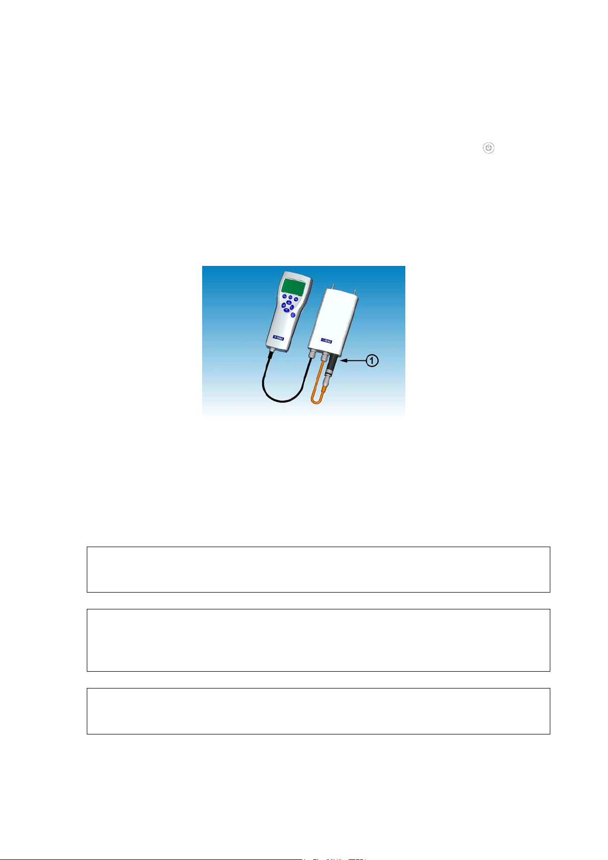
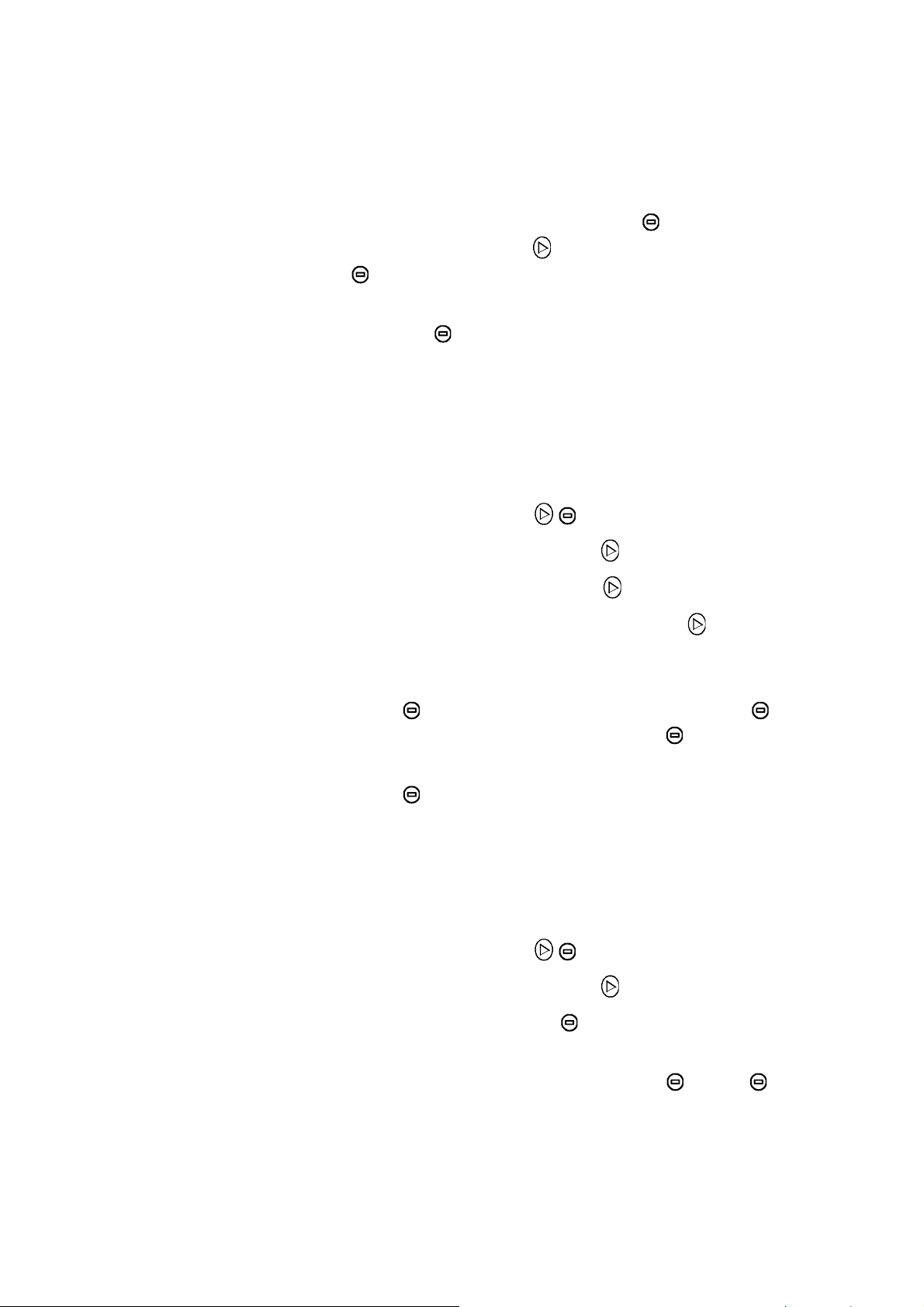
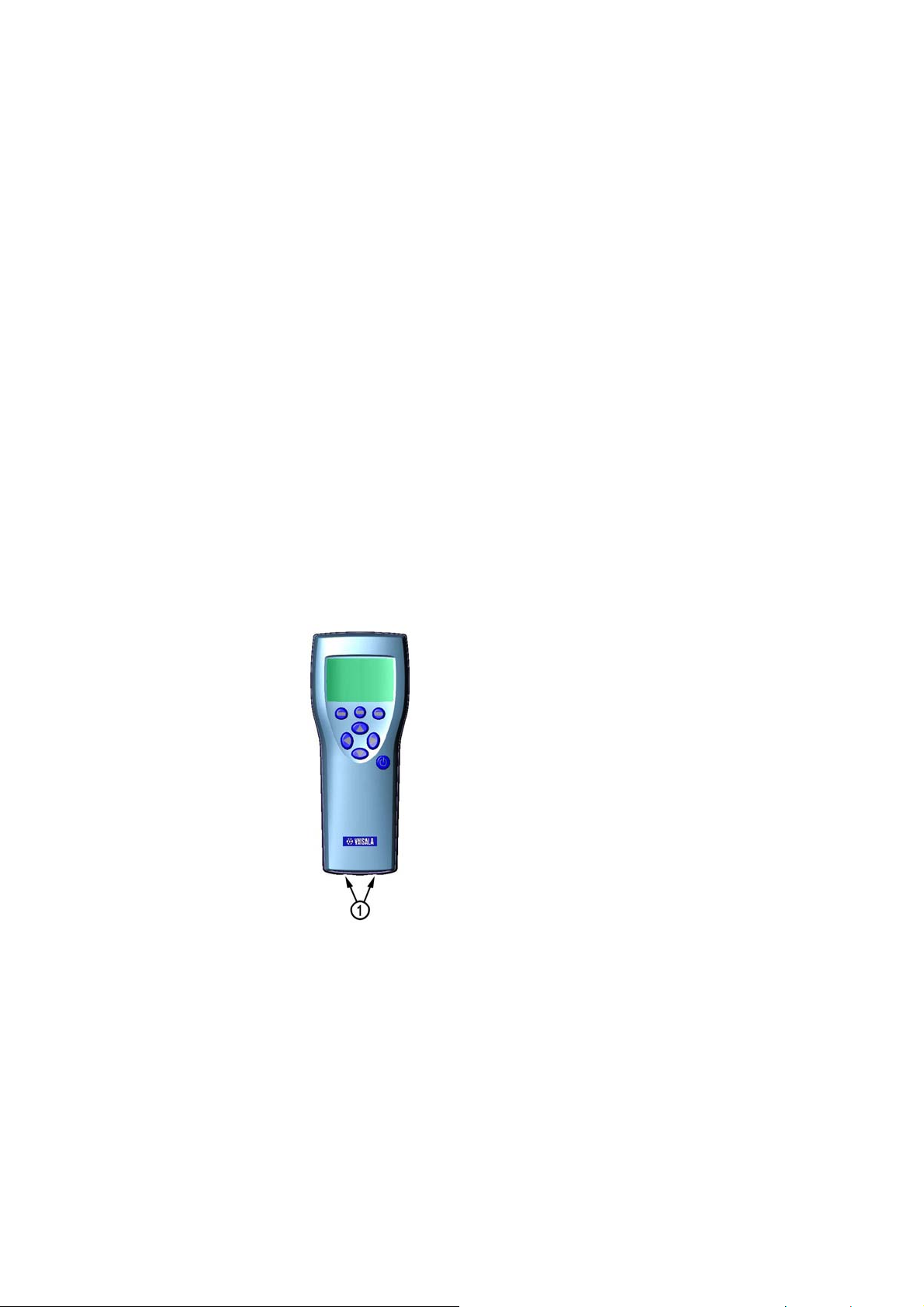
Parts Description
0505-221
Figure 1 GM70 Parts
The following numbers refer to
Figure 1 above:
1 = MI70 indicator
VAISALA _________________________________________________________ 13
Page 16

User's Guide_________________________________________________________
2 = Recharger connector
3 = Connector ports I and II for probes and cables
4 = Probe GMP221 or GMP222
5 = Probe fastener
6 = Handle GMH70
7 = Adjustment button
8 = Gas outlet
9 = ON/OFF switch
10 = Gas inlet
11 = Measuring chamber
12 = Probe GMP221 or GMP222
13 = Probe connector
14 = Connector to MI70 indicator
Probes
Probes GMP221 and GMP222 can be used with the GM70.
Table 1 presents the measuring ranges that can be can be
selected for the probes.
Table 1 GMP221 and GMP222 Measuring Ranges
Probe Measuring Range
GMP221 0...2%, 0...3%, 0...5%,
0...10%, 0...20% CO2
GMP222 0...2000 ppm, 0...3000 ppm,
0...5000 ppm, 0...7000 ppm,
0...10000 ppm
In order to obtain the best possible performance, it is
recommended that the measurement range is chosen so that
the actual concentrations to be measured are roughly in the
middle of the measuring range.
14 _____________________________________________________ M010139EN-D
Page 17

Chapter 2 _____________________________________________ Product Overview
GM70PUMP for Aspirated Sampling
GM70 Aspiration pump consists of a pump and a
measurement chamber for CO
is designed for checking of fixed CO
sampling from locations difficult to access. GM70PUMP is
connected to a MI70 indicator which displays the
measurement result. Pump system is powered through the
MI70 indicator.
measurements. GM70PUMP
2
transmitters and for
2
VAISALA _________________________________________________________ 15
Page 18

User's Guide_________________________________________________________
This page intentionally left blank.
16 _____________________________________________________ M010139EN-D
Page 19

Chapter 3 ________________________________________Preparations Before Use
CHAPTER 3
PREPARATIONS BEFORE USE
Recharging the Batteries
1. If using alkalines, unscrew the back plate of the
indicator and insert the alkalines. If the GM70 is
ordered with a rechargeable battery pack, the battery
pack is already in place as shipped from the factory.
2. Recharge the battery pack as follows: Plug in recharger
to the recharger connector of the indicator and connect
the recharger to wall socket. A battery symbol in
corner of display starts to roll.
- It is not recommended to use the GM70 during the
first recharging. Later on the GM70 can be used
while recharging.
- Duration of recharging depends on the charge level
of the battery pack being 4 hours typical. The
recommended first recharging time is 6 hours.
3. The battery pack is full when the battery symbol stops
to roll.
4. Disconnect the recharger.
VAISALA _________________________________________________________ 17
Page 20

User's Guide_________________________________________________________
Turning On and Setting Language, Date, and Time
1. Connect the probe handle (or the connector from the
GM70PUMP) to either of the connector ports of the
indicator.
2. Press the
3. Select the language by using
pressing
4. The default date presentation format is:
change the date, select Date and press
the date by using the
the date, press
select
M/D/Y date format (month/date/year), press ON.
button.
buttons. Confirm by
SELECT.
date.month.year. To
SET. Change
buttons. To confirm
OK. If you want to change the format,
5. The default time presentation format is 24-hour clock.
To change the time, select Time and press
SET.
Change the time by using arrow buttons. To confirm
the time, press
select
12-hour clock, press ON.
6. Press
settings, select
EXIT. To check and change the environment
OK. If you want to use 12-hour clock,
YES. Otherwise select NO, basic display
appears.
7. To ensure the best possible accuracy set the actual
pressure and temperature values to the GM70 as
follows:
- Select the pressure setting (P: 1013 hPa, default),
press
UNIT to select unit (hPa or bar), press SET,
set the pressure value by using arrow buttons. Press
OK to save the value.
- Select the temperature setting (T: 25.0 C°, default),
press
UNIT to select unit (°C or °F), press SET, set
the temperature value by using arrow buttons. Press
+/- to change the sign of the value. Press OK to save
the value.
8. Press
18 _____________________________________________________ M010139EN-D
EXIT to return to the basic display.
Page 21

Chapter 4 ______________________________________ Measuring Carbon Dioxide
CHAPTER 4
MEASURING CARBON DIOXIDE
The results of carbon dioxide measurements are affected by
the air pressure and the temperature of the measurement
conditions. For achieving the most accurate measurements
in high altitudes where the barometric pressure is clearly
lower than in the sea level, the actual atmospheric pressure
value should be set to the GM70. The acceptable pressure
value range is 700...1300 hPa.
NOTE
Before measurements ensure that the air pressure and
temperature settings are correct. Set the correct settings as
instructed on page
27.
Taking Measurements (Diffusion Sampling)
See Chapter 3 Preparations Before Use on page 17 if you
start the GM70 for the first time, otherwise follow the
instructions below:
1. Connect the probe cable to the MI70 indicator's
connector port.
2. Press
3. Wait for about 15 seconds to get the reading. For the
most accurate readings wait for 15 minutes to reach the
full operating state of the GM70.
POWER ON/OFF button.
VAISALA _________________________________________________________ 19
Page 22
User's Guide_________________________________________________________
4. Install the probe to the measuring position. Avoid
exhaling near the probe as this increases the CO
concentration.
5. The basic display opens, allow the reading to stabilize.
2
CAUTION
Handle the probe carefully. Strong impact or falling can
damage the probe.
If you need to disconnect the probe, first press
ON/OFF
settings and data are saved properly.
button to turn the indicator OFF. This ensures that all
POWER
Taking Measurements (Pump Aspirated Sampling)
See Chapter 3 Preparations Before Use on page 17 if you
start the GM70 for the first time, otherwise follow the
instructions below:
1. Connect one end of the sampling tube to the gas inlet
(marked with IN), in case of using a tube.
2. Connect the black cable of the GM70PUMP to the
MI70 indicator's connector port.
3. Plug in the recharger connector of the MI70 and
connect the recharger to wall socket.
4. Connect the GM220 probe to the probe connector of
the GM70PUMP.
5. Insert the probe in the measuring chamber. Note that to
have a tight installation, the two O-rings on the
opening of the measuring chamber should not match
together with the filter edge or the tapes on the probe
(see figure). When operating the pump, especially
when taking a sample from hot and humid conditions
into room temperature, take care that no condensation
forms on the probe.
20 _____________________________________________________ M010139EN-D
Page 23
Chapter 4 ______________________________________ Measuring Carbon Dioxide
6. Install the other end of the sampling tube to the
sampling location.
7. Turn on the MI70 indicator by pressing the
button.
8. Turn on the GM70PUMP.
9. The basic display opens.
10. Wait for a few minutes to get a stabilized reading. For
the most accurate readings wait for 15 minutes to reach
the full operating state of the GM70.
0505-222
NOTE
NOTE
NOTE
Figure 2 Properly Connecting the GM70PUMP
The following number refers to
Figure 2 above:
1 = Match the 2 O-rings together with the smooth probe
surface to have a tight connection!
Only one pump aspirated system can be connected to the
MI70 at a time.
When using the pump aspirated system it is recommended
to power the system by using the recharger connected to a
wall socket.
The battery indicator of the MI70 display does NOT show
the actual recharge level when the pump is in operation.
VAISALA _________________________________________________________ 21
Page 24
User's Guide_________________________________________________________
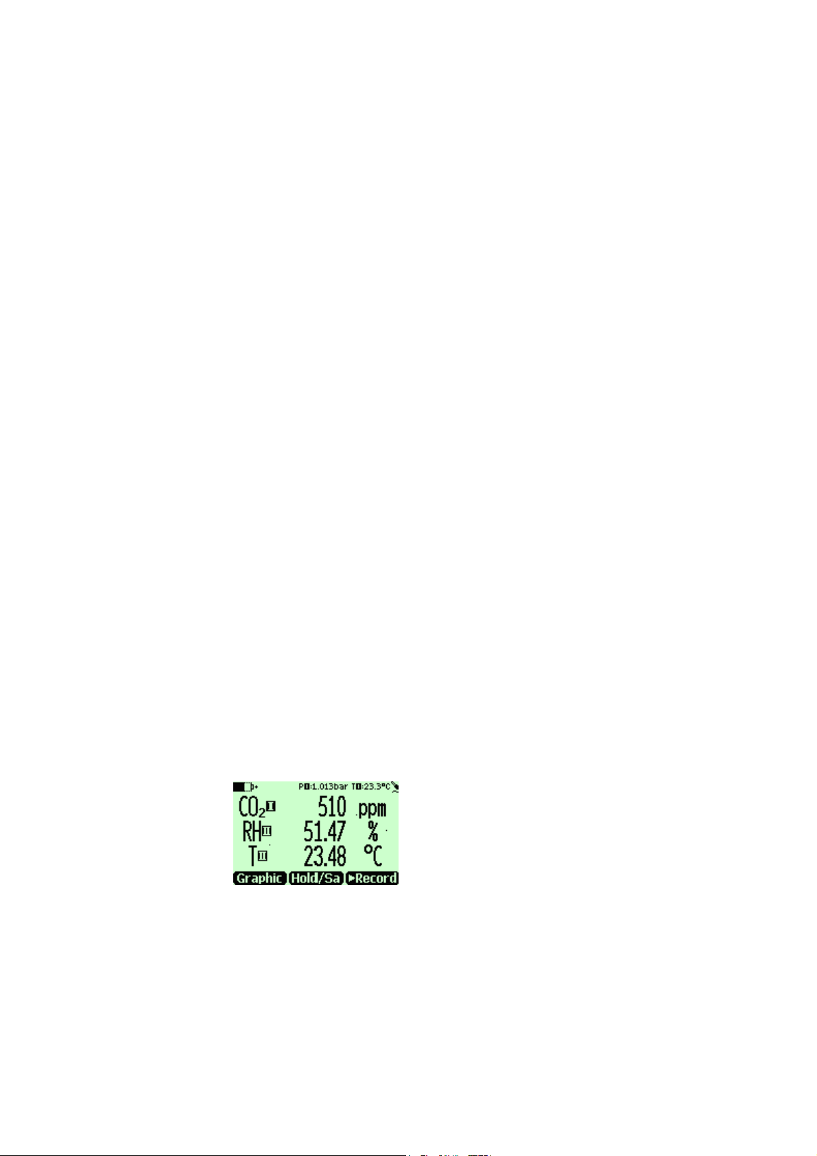
Measuring Other Parameters Simultaneously
Connect Vaisala interchangeable dewpoint (DMP) or
humidity (HMP) probe to the MI70 indicator's other
connector port to have simultaneous humidity measurement.
1. Connect the DMP70/HMP70 probe to the other
connector port in the bottom of the indicator.
2. Turn on the MI70 device.
3. Check that the pressure settings of the probes (port I
and II) are the same if you are taking measurements
from the same condition. You can use the HMP70
probe's temperature data to compensate the CO
measurement. In this case, select
YES when the MI70
asks you to check the environmental settings. Then
select temperature
T and press SET. Now the MI70 asks
if you want to link the measured T value to
environment parameter, press
LINK and EXIT.
2
4. The display now shows the reading of the port I probe
in the upper row(s) and the reading of the port II probe
in the lower row(s).
5. For achieving the most accurate measurements, set the
actual temperature value measured with the
temperature and humidity probe to the GM70.
0505-223
Figure 3 Example of the Display when the Carbon
Dioxide, and the Temperature and Humidity
Probe are Connected Simultaneously to the
MI70 Indicator
22 _____________________________________________________ M010139EN-D
Page 25
Chapter 5 ____________________________________Buttons, Displays, and Menus
CHAPTER 5
BUTTONS, DISPLAYS, AND MENUS
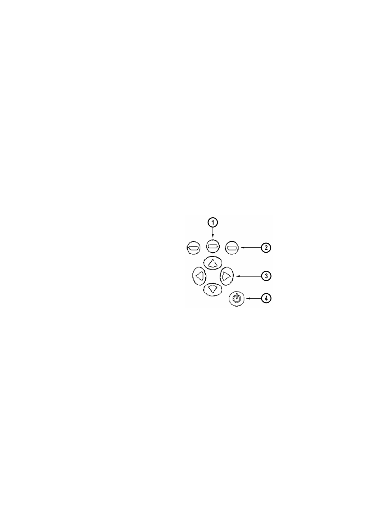
Buttons and Navigation
0505-224
Figure 4 MI70 Indicator Buttons
The following numbers refer to
1 = To open a menu view:
- Press an arrow button
- Press this shortcut button
2 = Shortcut buttons
3 = Arrow buttons
4 = Power ON/OFF
VAISALA _________________________________________________________ 23
Figure 4 above:
Page 26

User's Guide_________________________________________________________
Basic Display
0505-225
Press down and hold the
the indicator turns on/off.
Press the
above the button.
Press any of the
for the
ARROW buttons.
SHORTCUT buttons (2) to activate the function
ARROW buttons (3) to open the path
MENUS. In the MENUS you can navigate with the
POWER ON/OFF button (1) until
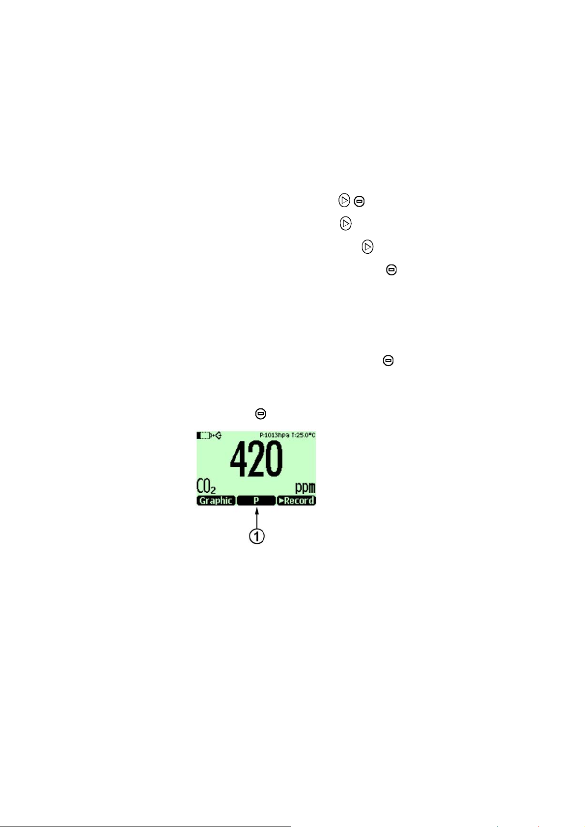
Figure 5 Basic Display
1. Selected unit, ppm or %.
2. Shortcut button
Graphic
1
changes display into the
graphical trend mode.
3. Shortcut button
Hold/Sa
1
freezes display and you may
save the reading into the memory.
4. Shortcut button
►Record
1
takes you to the Recording/Viewing
menu.
5. State of the battery.
6. Pressure and temperature settings.
7. Symbol which indicates that the GM70 is
communicating with a PC. If the PC cable is not
connected this symbol is not shown.
1
Graphic, Hold/Sa and Record-functions above the shortcut buttons
are set in the factory. You can however change them to refer
other functions (see
Changing the Shortcut Keys on page
33).
24 _____________________________________________________ M010139EN-D
Page 27
Chapter 5 ____________________________________Buttons, Displays, and Menus
Graphical Display
The graphical display shows you the measurements in the
form of a curve. From the curve you can examine the data
trend and the history data of the last minutes.
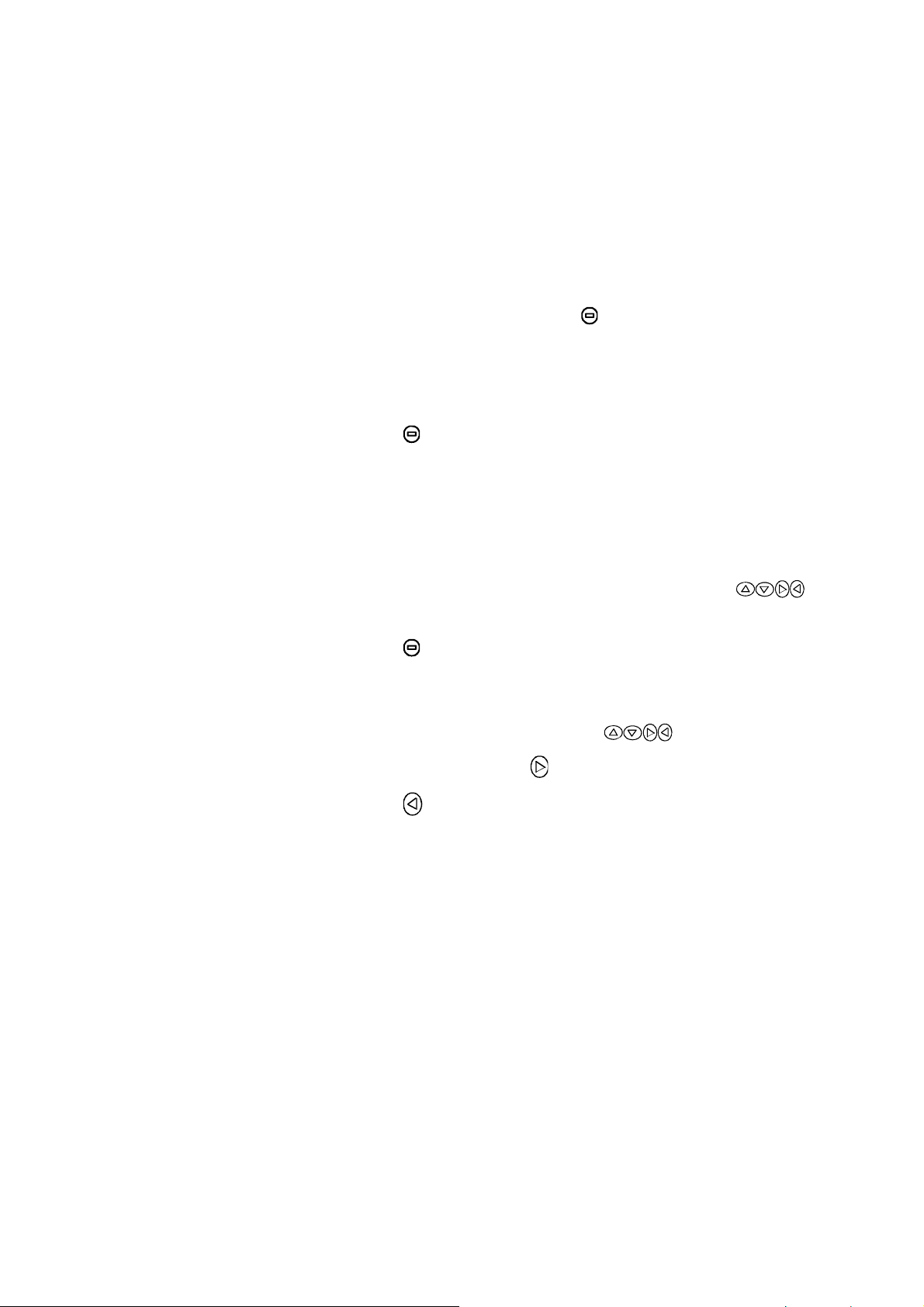
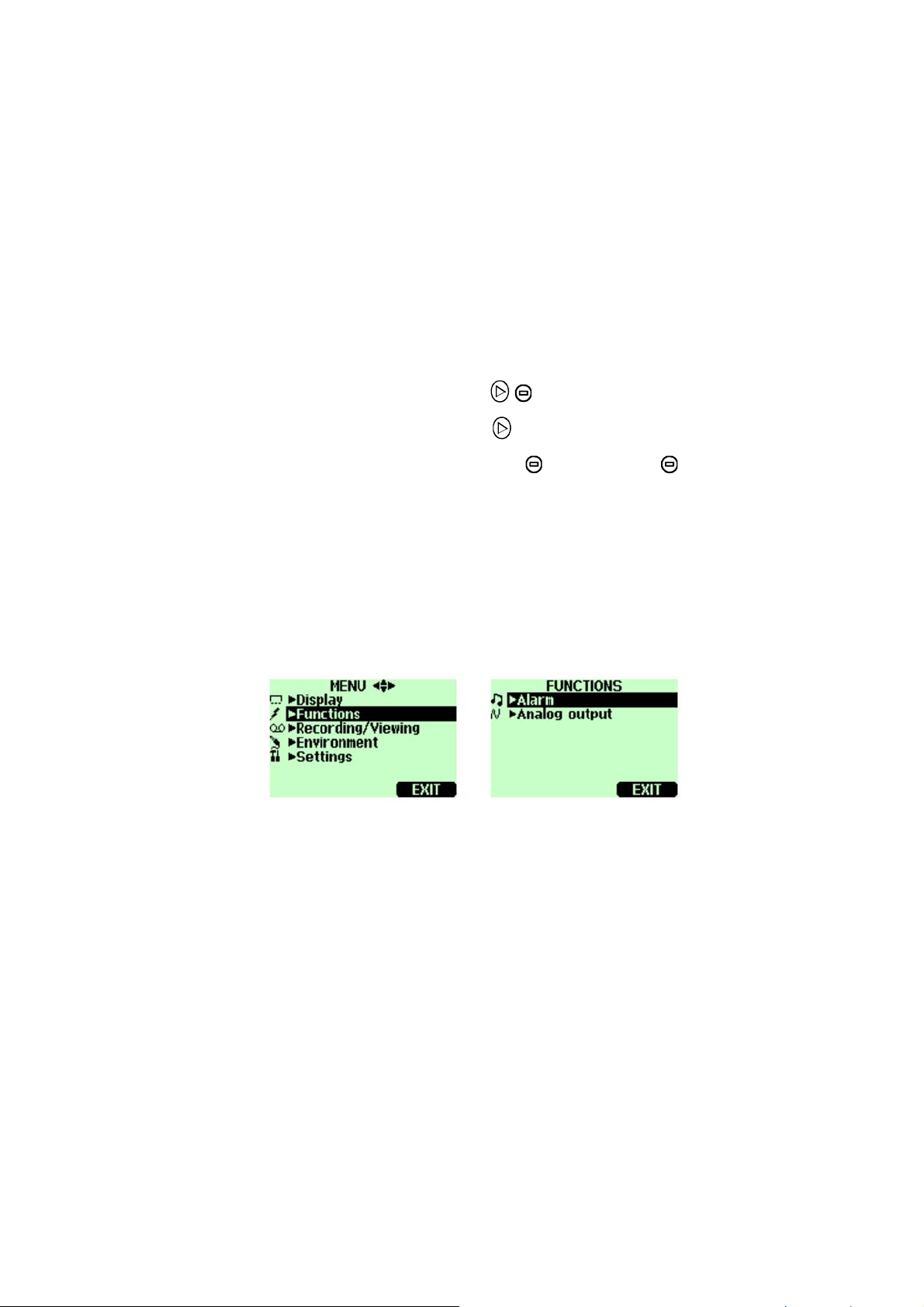
Menus
1. In the basic display, press
open the
2. Graphical display opens. More information in section
Graphic History on page 31.
3. Press
In the menus you can change settings and select functions.
1. Open the main menu by pressing any of the
buttons.
2. Press
returns if you do not open the
happens, start with item 1 again.
3. Move in the menus by using
MENU, select ►Recording/Viewing).
BACK to return to the basic display.
OPEN within 5 seconds. The basic display
Graphic or (alternatively
MENU shortly. If this
buttons.
4. Select the item with
5. Press
EXIT returns back to normal operation.
6.
VAISALA _________________________________________________________ 25
to return to the previous level.
button.
Page 28
User's Guide_________________________________________________________
0505-226
Figure 6 Menus
The following numbers refer to
Figure 6 above:
1 = Main menu
2 = Display menu
3 = Functions menu
4 = Recording/Viewing menu
5 = Environment menu
6 = Settings menu
26 _____________________________________________________ M010139EN-D
Page 29
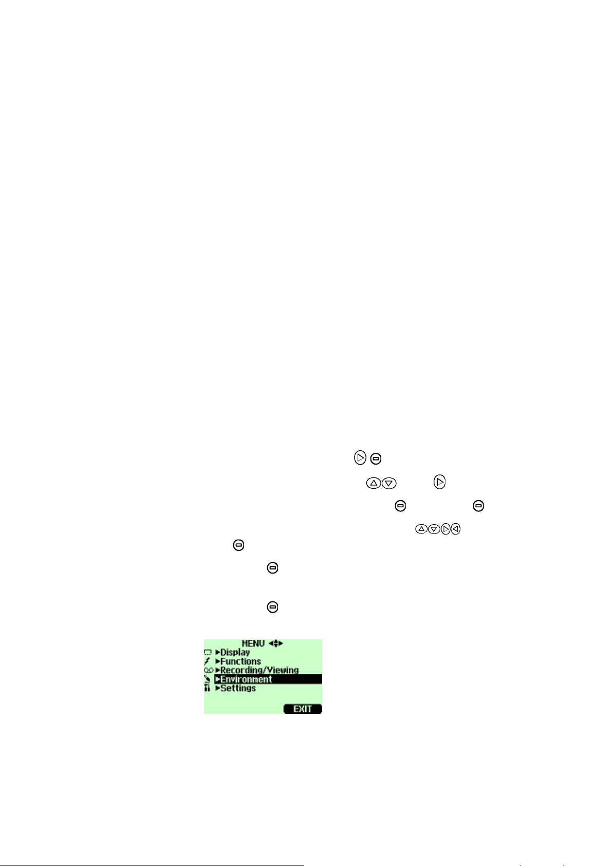
Chapter 6 _____________________________________________________ Settings
CHAPTER 6
SETTINGS
Setting Actual Pressure Value and Unit
For achieving the most accurate measurements in high
altitudes where the barometric pressure is clearly lower than
in the sea level, the actual atmospheric pressure value
should be set to the GM70. The acceptable pressure range is
700...1300 hPa. Pressure is given in the units of hPa or bar.
Follow the instructions below:
1. Open the
2. Select
3. Select pressure value, press
4. Set the pressure value by using
OK to save the value.
5. Press
hPa.
6. Press
0505-227
MENU, press OPEN.
►Environment with press .
UNIT , press SET.
UNIT to change the pressure unit. Default unit is
EXIT to return to the basic display.
buttons. Press
Figure 7 Environment Menu
VAISALA _________________________________________________________ 27
Page 30

User's Guide_________________________________________________________
Setting Actual Temperature Value and Unit
For achieving the most accurate measurements, the actual
temperature value should be set to the GM70. The
acceptable temperature range is -20...60ºC.
Follow the instructions below:
1. Open the
2. Select
3. Select temperature value, press
4. Set the temperature value by using
Press
5. Press
MENU, press OPEN.
►Environment with press .
SET.
buttons.
OK to save the value.
UNIT to change the temperature unit. Default
unit is ºC.
6. Press
EXIT to return to the basic display.
If you are using the HMP75 or other humidity probe, the
temperature information can be linked to compensate the
GM70's CO
reading.
2
28 _____________________________________________________ M010139EN-D
Page 31
Chapter 6 _____________________________________________________ Settings
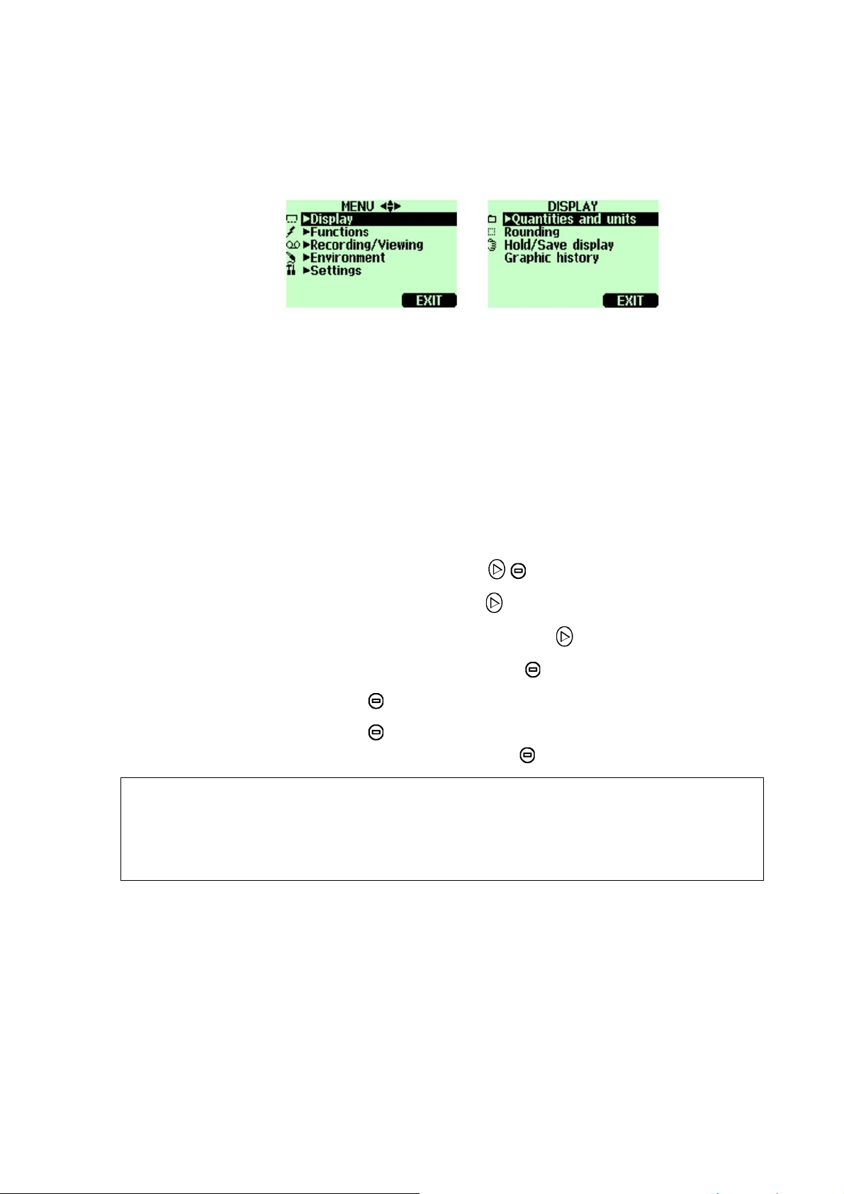
Display Settings
0505-228
Figure 8 Display Menu
Display Units
The unit of the measurement can be selected between ppm
and %. The default unit is ppm for measuring ranges with
upper limit of 10 000 ppm or less. For measuring ranges
with upper limit of 2...20%, the default unit is %.
NOTE
1. Open the
2. Select
3. Select
4. To change the unit, press
5. Press
6. Press
settings, otherwise press
MENU, press OPEN.
►Display, press .
►Quantities and units, press .
UNIT (ppm or %)
EXIT to return to the basic display.
YES, if you want to check the environment
NO.
Measurement units (ppm and %) express the CO2
concentration by gas volume.
1% CO
= 10 000 ppm CO2
2
VAISALA _________________________________________________________ 29
Page 32
User's Guide_________________________________________________________
Rounding
When using % units, you can select two or three decimal
display by using the Rounding function. The default setting
is rounding off (= three decimal display).
1. Open the
2. Select
3. Select
4. Press
Press
MENU, press OPEN.
►Display, press .
Rounding.
ON to have rounding on (two decimal display).
OFF to deactivate rounding (three decimal
display).
5. Press
EXIT to return to the basic display.
Hold/Save Display
Hold/Save function enables you to freeze a certain display
reading. This reading can be saved into the memory.
1. Open the
MENU, press OPEN.
2. Select
3. Select
4. Press
►Display, press .
Hold/Save display.
HOLD to freeze the display. The frozen
measurement data is displayed.
5. Press
SAVE to save the reading and EXIT to return to
the basic display.
6. You can save several readings with
HOLD-SAVE function.
The first saved reading is data point 1, the second
saved reading is data point 2 etc. All the individual
readings (data points) are stored in the same file
marked with
. The file remains in the indicator
memory even if the indicator is switched OFF.
30 _____________________________________________________ M010139EN-D
Page 33
Chapter 6 _____________________________________________________ Settings
7. To view the saved readings, press ►Record, select
►View recorded data, press .
8. Select the file marked with
see the saved data readings. Press
, press . Now you can
TIMES to see the
recording timestamps.
9. Press
EXIT to return to the basic display.
Graphic History
Graphic history shows you the data curve from the time the
device was turned on.
1. Open the
2. Select
3. Select
history display.
4. To get the statistical info on the graph area (minimum,
maximum and mean values), press
MENU, press OPEN.
►Display, press .
Graphic history, press SHOW to have a graphical
INFO.
5. To get the curve of the other selected quantities, press
NEXT until text ALL is shown, press ALL.
6. To zoom in on the curve, press the arrow button
zoom out, press the button
horizontal directions, press the buttons
7. Press
User Interface
0505-229
Figure 9 User Interface Settings Menus
NEXT. To get the curves of all the quantities, press
. To
. To move the curve in
.
BACK and EXIT to return to the basic display.
VAISALA _________________________________________________________ 31
Page 34
User's Guide_________________________________________________________
Selecting Language
You can select any of the following languages as a user
interface language: English, German, French, Finnish,
Spanish or Swedish.
1. Open the
2. Select
3. Select
4. Select
5. Select the language you want, press
6. Press
MENU, press OPEN.
►Settings, press .
►User interface, press .
Language, press SET.
SELECT.
EXIT to return to the basic display.
If you accidentally select a wrong language, first go back to
the basic display by pressing
(right) as many times as
required, then go to the language selection menu by
pressing:
, (middle) , , , (middle).
Automatic Power Off
As shipped from the factory, the GM70 has a default setting
which turns the power off automatically after 15 minutes of
inactivity. This is to save the battery. In case you want to
change the inactivity time setting to 60 minutes or turn off
the automatic power off function, follow the instructions
below:
1. Open the
2. Select
3. Select
4. Select
5. Select the choice you want, press
6. Press
32 _____________________________________________________ M010139EN-D
MENU, press OPEN.
►Settings, press .
►User interface, press .
Auto power off, press SET.
SELECT.
EXIT to return to the basic display.
Page 35
Chapter 6 _____________________________________________________ Settings
Changing the Shortcut Keys
By default the three shortcut keys refer to the functions
Graphic, Hold/Save and Record. However the shortcut keys
for the functions can be changed to meet your needs.
1. Open the
2. Select
3. Select
4. Select
MENU, press OPEN.
►Settings, press .
►User interface, press .
Program shortcut keys, press START.
5. Press the shortcut key you want to change, for
example:
6. If you want to replace
Hold/Save.
Hold/Save with pressure setting
function, select pressure setting by using arrow
buttons,
confirm your selection, otherwise answer
►Environment→P, press SELECT. Answer YES to
NO and
continue from item 4.
7. Press
EXIT to return to the basic display.
0505-230
Figure 10 Changing the Shortcut Keys
The following number refers to
1 =
Hold/Save-shortcut key replaced by pressure setting
shortcut key
P
Figure 10 above:
VAISALA _________________________________________________________ 33
Page 36
User's Guide_________________________________________________________
Key Click and Backlight On Key Press
1. Open the MENU, press OPEN.
2. Select
3. Select
►Settings, press .
►User interface, press .
4. To turn the sound effect while pressing the buttons
OFF or ON, select
Key click and press ON/OFF.
5. To turn the backlight effect while pressing the buttons
OFF or ON, select
6. Press
EXIT to return to the basic display.
Backlight on key press ON/OFF.
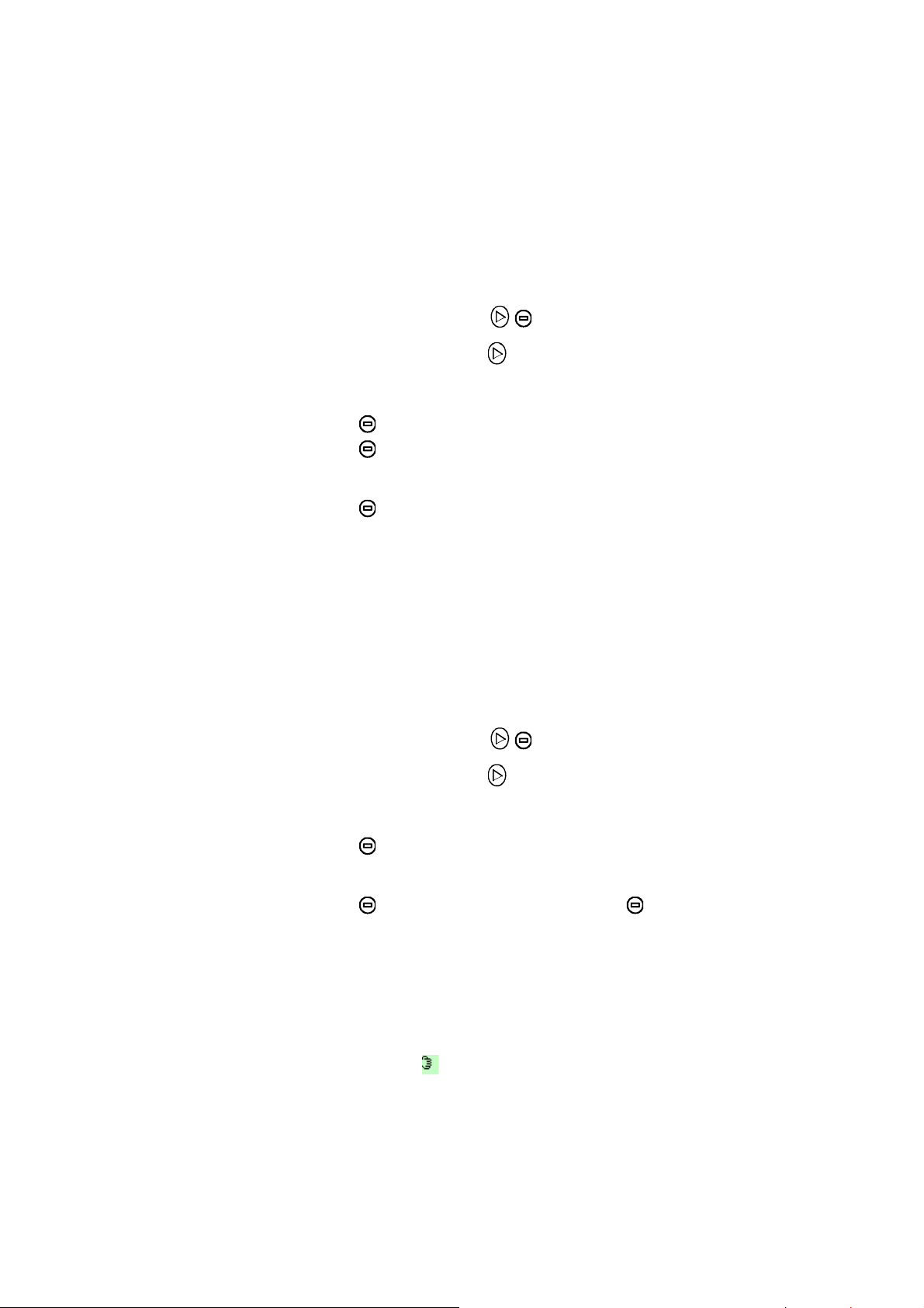
Setting Date and Time
1. Open the MENU, press OPEN.
2. Select
3. Select
4. The default date presentation format is year-month-
date. For example 2002-02-01. To change the date,
select
arrow buttons. To confirm the date, press.
want to change the format, select
(date.month.year) or
(month/day/year), press
►Settings, press .
►Date and time, press .
Date and press SET. Change the date by using
OK. If you
D.M.Y
M/D/Y date format
ON/OFF.
5. The default time presentation format is 24-hour clock.
To change the time, select
Time and press SET. Change
the time by using arrow buttons. To confirm the time,
press
hour clock, press
6. Press
34 _____________________________________________________ M010139EN-D
OK. If you want to change the format, select 12-
ON/OFF.
EXIT.
Page 37
Chapter 6 _____________________________________________________ Settings
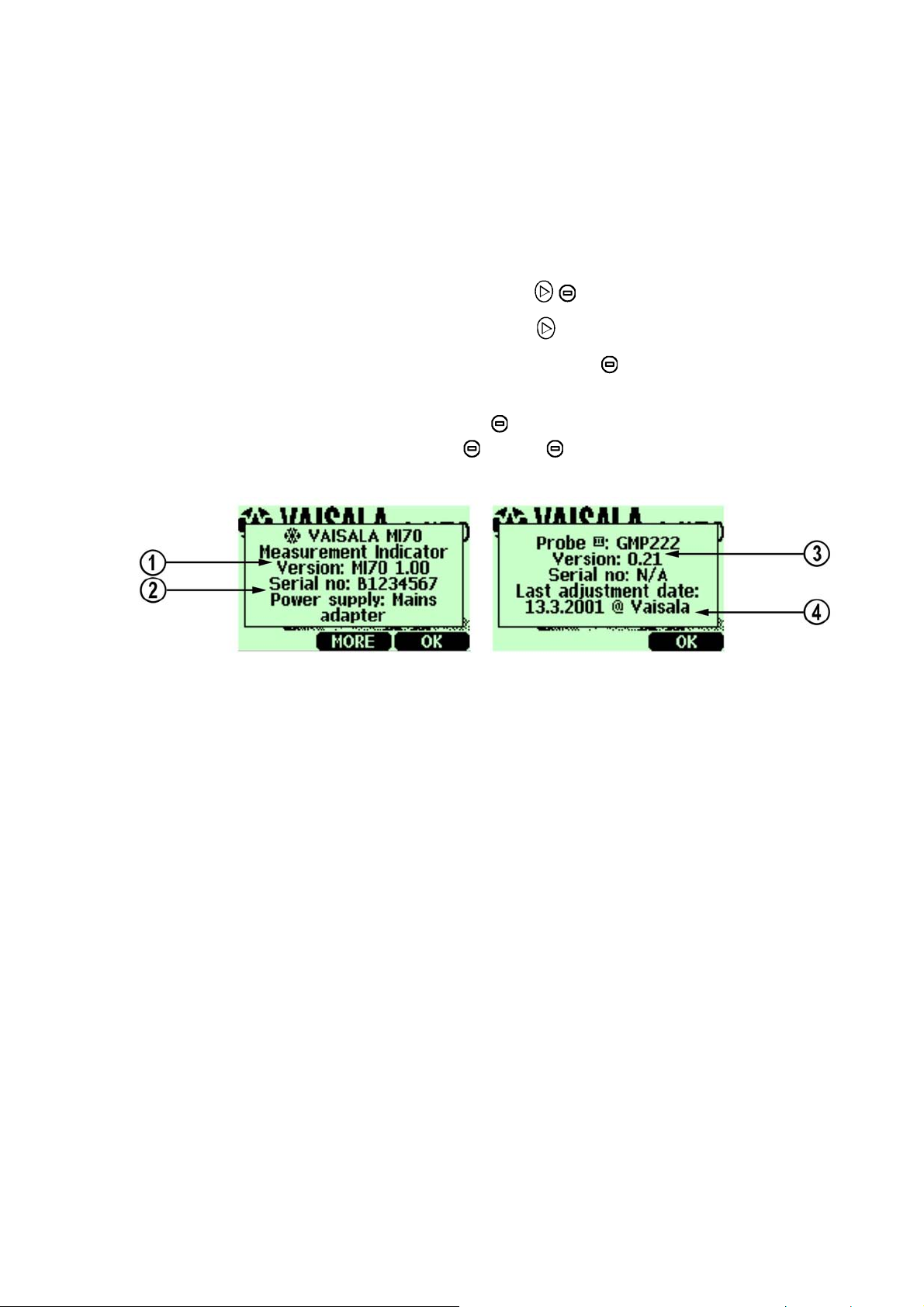
Device Information
The basic information about the indicator and the probe is
found as follows:
1. Open the
2. Select
3. Select
MENU, press OPEN.
►Settings, press .
►Device information, press SHOW.
4. The first display gives the information on the MI70
indicator. Press
probe. Press
MORE to get the information on the
OK and EXIT to return to the basic
display.
0505-231
Figure 11 Device Information Displays
The following numbers refer to
Figure 11 above:
1 = Software version of the MI70 indicator
2 = Serial number of the MI70 indicator
3 = Software version of the probe
4 = Location of the last adjustment (alternatives:
Vaisala, GM70, or GMK220)
VAISALA _________________________________________________________ 35
Page 38
User's Guide_________________________________________________________
Reverting Factory Settings
Factory settings of the indicator only can be reverted to
clear all changed settings and data memory of the indicator.
Reverting factory settings of the indicator does not affect the
probe calibration. Factory calibration of the probe cannot be
reverted if adjustment is made (see
and Adjusting the Probes on page
Chapter 10 Calibrating
49).
1. Open the
2. Select
3. Select
confirm the reverting.
4. The power turns off automatically. When switching on
again, the factory settings are reverted. You need to set
the language, date, and time again. See
Other Settings
0505-232
MENU, press OPEN.
►Settings, press .
Factory settings, press REVERT. Press YES to
Chapter 3.
Figure 12 Other Settings Menu
Setting the Alarm Levels
Two alarm levels can be set. Alarming state is OFF in
between the set points. Alarming state is ON when CO
concentration is below level 1 or above alarm level 2. For
example, if you want to set ON the alarm when
concentration exceeds 1000 ppm, set the first level as 0 ppm
and the second level as 1000 ppm. When alarming is ON,
GM70 starts to beep and display backlight starts to blink.
36 _____________________________________________________ M010139EN-D
2
Page 39
Chapter 6 _____________________________________________________ Settings
1. Open the MENU, press OPEN.
2. Select
3. Select
4. Select the first limit, press
►Settings, press .
►Alarm, press .
(if the alarm function is
ON, take it OFF). Set the alarm level by using arrow
buttons. Press
OK to save the setting.
5. If needed, select the second limit, and then follow
instructions from item 6. The alarm will go off when
the upper limit is exceeded or when lower limit is gone
below.
6. Select
Alarm ON/OFF, press ON to activate the alarm and
return back to the basic display.
7. A note picture sign
appears on the upper left corner
of the basic display.
8. When the alarm level is reached, you can stop alarming
by pressing
answer
answer
OK. To reactivate the alarm function,
YES. To stop the alarm function completely,
NO.
VAISALA _________________________________________________________ 37
Page 40

User's Guide_________________________________________________________
This page intentionally left blank.
38 _____________________________________________________ M010139EN-D
Page 41
Chapter 7 ______________________________________ Analog Output Connection
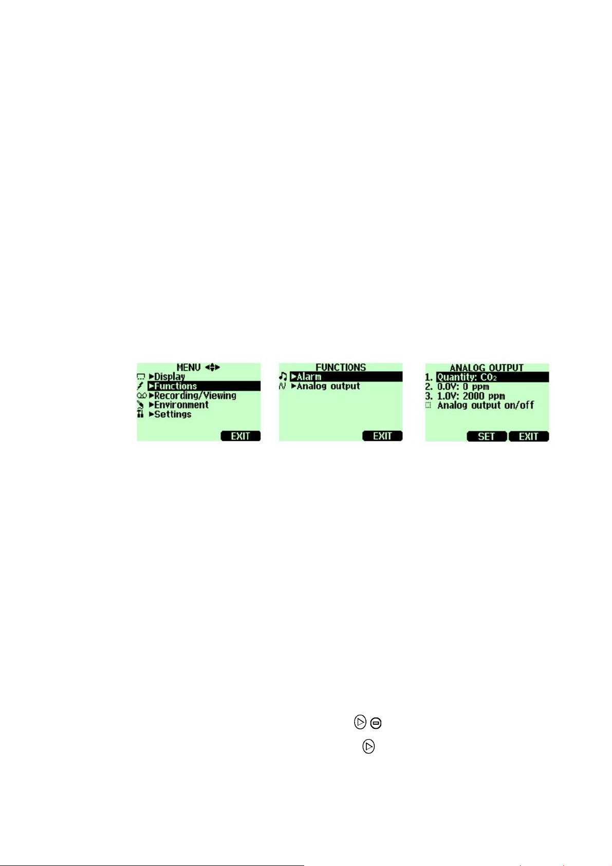
CHAPTER 7
ANALOG OUTPUT CONNECTION
Selecting and Scaling the Analog Output
0505-233
Figure 13 Selecting Analog Output
To get analog measurement data you need an analog output
signal cable, see list of accessories on page
voltage signal channel 0...1.0V is available. You can scale
the output to any output range but it is recommended to
have the scaling within the probe's measuring range to get
accurate measurements.
1. Connect the analog output signal cable connector to the
indicator base connector. Connect the screw terminal
block as follows:
Brown wire: common wire (-)
Yellow-green wire: signal (+)
2. Open the
MENU, press OPEN.
68. One scalable
3. Select
VAISALA _________________________________________________________ 39
►Functions, press .
Page 42
User's Guide_________________________________________________________
4. Select ►Analog output, press .
5. Select
press
0.0 V to set the value for the 0.0V output signal,
SET (If the analog output is ON, take it OFF).
Set the low value by using the arrow buttons. Press
OK to make the setting.
6. Select
press
buttons. Press
value. Press
7. Select
1.0V to set the value for the 1.0V output signal,
SET. Set the high value by using the arrow
+/- button to choose the sign of the
OK to make the setting.
Analog output on/off, press ON to activate the analog
output and return back to the basic display.
8. A wire picture sign
appears on the upper left corner
of the basic display.
9. To deactivate the analog output function, go to
►Functions ►Analog output ►Analog output on/off
and press OFF.
MENU
40 _____________________________________________________ M010139EN-D
Page 43
Chapter 8 _______________________________________________ Recording Data
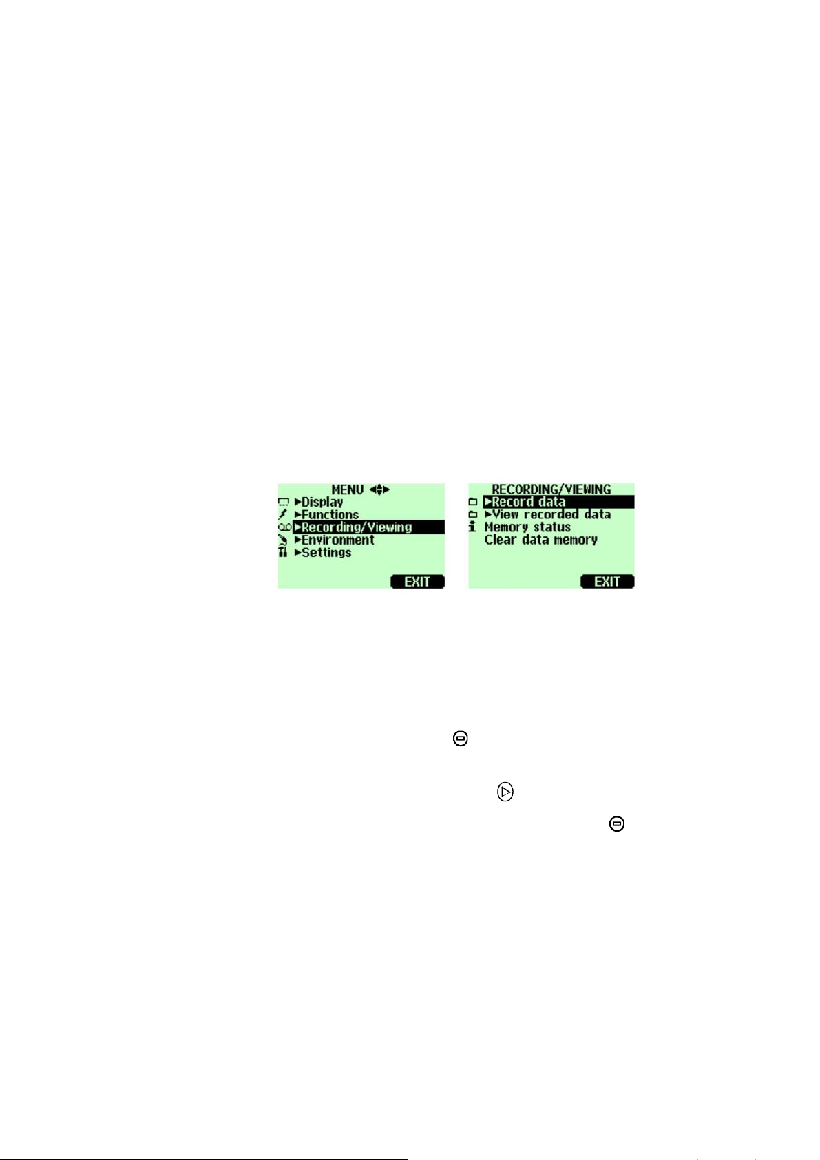
CHAPTER 8
RECORDING DATA
Recording
0505-234
Figure 14 Recording Data
You can record measurement data and view the recorded
data on the display.
1. Press the shortcut
MENU, select ►Recording/Viewing).
2. Select
3. To change interval, select
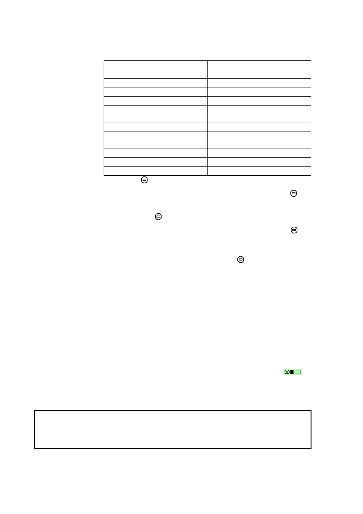
4. Select the measurement interval with the arrow
buttons. The measurement intervals and the maximum
recording times are shown in the following table.
►Record data, press .
►Record, (alternatively open the
Interval, press SET.
VAISALA _________________________________________________________ 41
Page 44
User's Guide_________________________________________________________
Measurement interval Maximum recording
duration (= memory full)
1 second 45 minutes
5 seconds 3 hours
15 seconds 11 hours
30 seconds 22 hours
1 minute 45 hours
5 minutes 9 days
15 minutes 28 days
30 minutes 56 days
1 hour 113 days
3 hours 339 days
12 hours 1359 days
5. Press SELECT.
6. To set the recording duration, select
Duration, press SET.
7. Select the recording duration with the arrow buttons
and press
8. Start recording: select Start/Stop recording, press
START. If you choose 'Memory full', you see the
SELECT.
maximum recording time on the display. You can also
delete files to free memory. Press
START again to
accept maximum recording time.
9. It is recommended to have power on during recording
to get the most accurate measurements. In long lasting
recordings, power the GM70 via the charging adapter.
Ensure that the automatic power off function is
deactivated. In battery use, you can switch off power
during recording to save battery, but then the accuracy
is not necessarily within accuracy specifications. A
display message tells you that recording continues
undisturbed even when power is off. If the indicator is
switched off during recording, the progress bar
is
shown on the display every 10 seconds (all the time if
the charging adapter is connected).
CAUTION
Do not disconnect the probe when the data recording is on
even if the indicator is off. This may cause loss of recorded
data.
42 _____________________________________________________ M010139EN-D
Page 45
Chapter 8 _______________________________________________ Recording Data
Stop Recording
1. To stop recording, press shortcut ►Record, select
►Record data and press , select Start/Stop recording and press
STOP.
2. Now you can go and view the recorded file by
selecting
SHOW.
You can save individual measurement data points with
Hold/Save function described in page 30.
Viewing Recorded Data
1. Open the MENU, press OPEN.
2. Select
3. Select
►Recording/Viewing, press .
►View recorded data, press .
4. Select the file you want to view, press
identified according to the starting date and time of
recording.
5. Press
GRAPH to get the graphical view, press TIMES to
get the recording timestamps (press
to the recording values).
6. Press
EXIT to return to the basic display.
Checking Memory Status
You can check how much free space there is in the memory.
1. Open the
2. Select
MENU, press OPEN.
►Recording/Viewing, press .
. The files are
VALUES to go back
3. Select
Memory status, press SHOW to see the amount of
memory in use and the estimated free space.
4. To return to the basic display, press
VAISALA _________________________________________________________ 43
OK and EXIT.
Page 46

User's Guide_________________________________________________________
Deleting All Recorded Files
The data memory can be cleared as follows:
1. Open the
2. Select
3. Select
confirm deletion of all recorded data files.
4. To return to the basic display, press
MENU, press OPEN.
►Recording/Viewing, press .
Clear data memory, press CLEAR. Press YES to
Transferring Recorded Data to PC
The recorded data can be transferred to a PC by using the
MI70 Link program.
The MI70 Link program can be ordered from Vaisala, see
list of accessories on page
recorded data easily in Windows™ environment and further
transfer it into a spreadsheet program (such as Microsoft
Excel) for modification.
68. You can examine the
EXIT.
®
Real-Time Monitoring with PC
You can monitor the GM70 readings directly with a PC by
using the MI70 Link program. The MI70 Link program can
be ordered from Vaisala, see list of accessories on page
68.
44 _____________________________________________________ M010139EN-D
Page 47
Chapter 9 ______________________________ Field Checking of Fixed Transmitters
CHAPTER 9
FIELD CHECKING OF FIXED TRANSMITTERS
Field Checking of the Vaisala GMD/W20 Series Transmitters (Diffusion Sampling)
0505-235
Figure 15 Location of the MI70 Connector Ports
The following number refers to Figure 15 above:
1 = Connectors for the GMA70 cable
VAISALA _________________________________________________________ 45
Page 48

User's Guide_________________________________________________________
Check the reading of a fixed transmitter by using the GM70
as a reference. Both readings can be seen on the GM70's
display simultaneously when using a connecting cable
GMA70 (see the list of accessories).
1. Connect the end of the GMA70-cable to either of the
GM70's connector ports located on the bottom of the
indicator.
2. Connect the other end of the GMA70-cable to the
SERIAL COM pin connector of the GM20 transmitter's
motherboard.
3. Turn on the MI70 indicator.
4. Set the GM70 probe next to the transmitter to be
checked. Ensure that the probes are located in the same
conditions. Avoid exhaling towards the probe as this
alters the CO
concentration and disturbs the readings.
2
5. The reading of the transmitter is shown on the first or
middle row of the display, depending on which
connector is used. Value of connector I is shown on the
upper row of the display. Value of connector II is on
the lower row of the display. The difference of the
readings is shown on the lowest row.
6. Compare the readings. In case there is a need for an
adjustment, send the transmitter to a Vaisala Service
Center to be adjusted or make an adjustment by using a
calibration software kit (19222GM).
Field Checking of the Vaisala GMD/W20 Series Transmitters (Pump Aspirated Sampling)
The pump aspirated system feeds the same gas sample to
both the reference probe and the transmitter to be checked.
Both readings can be seen on the GM70's display
simultaneously when using a connecting cable GMA70 (see
the list of accessories).
46 _____________________________________________________ M010139EN-D
Page 49

Chapter 9 ______________________________ Field Checking of Fixed Transmitters
1. Connect the GMA70 cable between the MI70
indicator's connector port and the
SERIAL COM pins in the
motherboard of the GM20 transmitter. If not using the
GMA70 cable, check the transmitter reading from the
transmitter output.
2. Connect one end of the sampling tube to the gas inlet
(marked with IN) of the GM70PUMP.
3. Connect the other end of the tube.
4. GMD20: to the sampling port located in the middle of
the GMD20's motherboard (protected with a yellow
cap).
5. GMW20: to the sampling port located on the
GMW20's motherboard (protected with a yellow cap).
6. Insert the calibrated GM220 probe to the measuring
chamber of the GM70PUMP.
NOTE
7. Turn on the MI70 indicator and the GM70PUMP.
8. Compare the readings. In case there is need for an
adjustment, send the transmitter to a Vaisala Service
Center to be adjusted or make an adjustment by using a
calibration software kit (19222GM).
Please do not breathe towards the transmitter when
checking the readings.
VAISALA _________________________________________________________ 47
Page 50

User's Guide_________________________________________________________
Field Checking of the GMT220 (Without a Display)
Follow the instructions below to check the operation of a
GM220 series probe.
1. Check the display reading of the GM70.
2. Turn off the GM70.
3. Detach the GM70's probe as follows:
- Loosen the plastic probe fastener (item 7, Figure 1)
by unscrewing it about 5 turns.
- Take a firm hold from the base of the probe and pull
strongly until the probe comes loose.
4. Detach the GM220 probe from the transmitter base
(open the cover, loosen the tightening screw and pull
the probe out).
5. Insert the GM220 probe to the GM70 handle as deep as
possible. Turn the probe inside the handle until you
feel that a step in the probe connector snaps into the
groove of the probe handle connector and locks the
probe.
6. Tighten the probe fastener.
7. Turn on the GM70.
8. Compare the readings of the GM70 and the transmitter
probe to be checked.
9. If there is need for an adjustment, please contact
Vaisala Service Center or adjust the probe according to
the instructions in
Adjusting the Probes on page
Chapter 10 Calibrating and
49.
You can also connect the GMA70 cable between the
GMT220 and the GM70 as described in the previous
section.
48 _____________________________________________________ M010139EN-D
Page 51

Chapter 10 _____________________________ Calibrating and Adjusting the Probes
CHAPTER 10
CALIBRATING AND ADJUSTING THE PROBES
In this user's guide the term calibration means comparing
detector's reading to a reference concentration. In adjusting,
which is usually done after calibration, the reading of the
detector is changed to correspond to the reference
concentration.
After adjustment, the original calibration certificate shipped
with the product is not valid anymore.
Calibration Interval
The GM70 is fully calibrated and adjusted as shipped from
factory. The recommended calibration interval is two years.
However, calibration should always be done whenever there
is reason to believe that the device is not within the accuracy
specifications. The length of the suitable calibration interval
may vary depending on the conditions and frequency of use.
Factory Calibration and Adjustment
It is recommended to send the GM70 probe to Vaisala
Service Centers for accurate calibration and adjustment, see
contact information on page
63.
VAISALA _________________________________________________________ 49
Page 52
User's Guide_________________________________________________________
Calibration and Adjustment by the User
The GM70 can be calibrated and fine control adjustment can
be carried out by the user. Note that this adjustment does not
correspond to the accurate factory adjustment. The user
adjustment is recommended only if the reading error is less
than 10% of the measuring range in the low-end and less
than 20% of the measuring range in the high-end. The
calibration report supplied with the product is not valid after
the adjustment.
CAUTION
NOTE
You cannot revert to factory settings after the user
adjustment!
Adjustment is carried out
- by using reference gases and a field check adapter,
- by comparing two probes: the one to be adjusted and the
other a calibrated probe.
Adjustment cannot be done with the GM70PUMP.
To open the adjustment mode you need to press the
adjustment button (
The GMH handle does not meet the IP65 classification
requirements after removal of the screw that covers the
adjustment button.
Figure 16) located in the probe handle.
0505-236
Figure 16 Location of the Adjustment Button
50 _____________________________________________________ M010139EN-D
Page 53

Chapter 10 _____________________________ Calibrating and Adjusting the Probes
The following number refers to Figure 16 on page 50:
1 = Adjustment button (before adjusting, take out the
screw which covers the button).
Adjustment with Reference Gases
Equipment Needed
For the adjustment procedure with gases, you need the
probe to be adjusted, accurate reference gas(es), a pressure
regulator, a flow meter, a field check adapter (can be
ordered from Vaisala) and flexible tubing with 3 mm (1/8")
inner diameter.
Reference Gases
NOTE
To achieve reliable results reference gases shall be traceable
to appropriate standards (for example NIST).
- If adjustment is done by using one reference gas (one-
point adjustment), concentration of the gas should be near
to the concentration values in which the device is used.
It must be noted that when adjustment is done only in one
point, this results high accuracy only near to the adjustment
point, not necessarily over the whole measurement range.
- When using two reference gases (two-point adjustment),
the reference gas concentrations should represent the lowend and the high-end of the measuring range. The lowend concentration should be less than 20% of the
measuring range of the probe. The zero gas can be N
with a purity of N5.0 (or better). The high-end gas can be
mixture of CO
upper limit of the measuring range, being 110% of the
range at maximum. Accuracy of the concentrations
should be 1% (or better). Difference between the
reference gas concentrations should be more than 20% of
the measuring range.
and N2 with concentration near to the
2
gas
2
VAISALA _________________________________________________________ 51
Page 54
User's Guide_________________________________________________________
Two-Point Adjustment Procedure
CAUTION
Please take special care regarding the following when
carrying out the adjustment:
- Check that you give the correct reference concentrations
in the correct units.
- Check that the reading has really stabilized before
accepting the reading.
You cannot revert the factory settings after the adjustment!
1. Insert the probe into the field check adapter until the
perforated filter is covered.
0505-237
Figure 17 Field Check Adapter
2. Connect the tubing to the bottom port of the adapter.
3. Connect the adapter with the tubing to the flow meter,
the pressure regulator and further to the low-end
reference gas bottle. The side port of the adapter is left
open for gas outflow.
4. Let the low end reference gas flow and stabilize with a
flow rate of about 0.6 l/min. Follow the reading of
GM70, and after it has stabilized, wait for 6 more
minutes.
5. Take out the screw from the GM70 probe handle to
expose the adjustment button (see
Press the button with a small screwdriver. When
52 _____________________________________________________ M010139EN-D
Figure 16, page 50).
Page 55

Chapter 10 _____________________________ Calibrating and Adjusting the Probes
pressing the button, the indicator turns to adjusting
mode.
6. Press
7. Select
8. Press
temperature values. To continue adjusting press
9. Now the adjustment mode is on. Press
OK to confirm the adjusting.
CO2, press SELECT.
YES to give the ambient pressure and
EXIT.
GRAPH to
confirm that the readings have stabilized. Go back and
press
10. Select
ADJUST to select the adjustment method.
2-point adjustment, press SELECT. Press READY with
the stabilized reading in the lower reference
concentration.
11. Give the lower reference concentration value by using
the arrow buttons (for example, if you are using pure
nitrogen, enter value 0 ppm). Take care that you give
the correct value in correct units, as you cannot revert
the earlier values after accepting the new values. Press
OK.
Next move on to the adjustment at the second (highend) reference point.
12. Take out the tubing from the low-end gas bottle and
connect it to the high-end gas bottle.
13. Let the high end reference gas flow and stabilize with a
flow rate of 0.6 l/min. Follow the reading of GM70,
and after it has stabilized, wait for 6 more minutes.
14. Press
READY with the stabilized reading in the higher
reference concentration.
15. Give the high-end reference concentration value by
using the arrow buttons. The analyzed CO
2
concentration of the reference gas is typically printed
on the bottle.
Take care that you give the correct value in correct
units, as you cannot revert the earlier values after
accepting the new values. Press
OK.
VAISALA _________________________________________________________ 53
Page 56
User's Guide_________________________________________________________
16. Confirm the adjustment, press YES. By pressing NO
you return to adjustment mode display. (If the
difference between the two references is less than 20%
of the measuring range of the probe, adjustment cannot
be done).
CAUTION
17. Adjustment is complete. Press
the basic display.
18. Shut off the gas flow.
19. Replace the screw onto the adjusting button.
BACK-EXIT to return to
One-Point Adjustment Procedure
Please take special care regarding the following when
carrying out the adjustment:
- Check that you give the correct reference concentrations
in the correct units.
- Check that the reading has really stabilized before
accepting the reading.
You cannot revert the factory settings after the adjustment!
1. Insert the probe into the field check adapter (as deep as
possible, the perforated filter cover should be
completely inside the adapter).
2. Connect the tubing to the bottom port of the adapter.
3. Connect the adapter with the tubing to the flow meter,
the pressure regulator and further to the reference gas
bottle. The side port of the adapter is left open for gas
outflow.
4. Let the reference gas flow and stabilize with a flow rate
of 0.6 l/min. Follow the reading of GM70, and after it
has stabilized, wait for 6 more minutes.
54 _____________________________________________________ M010139EN-D
Page 57
Chapter 10 _____________________________ Calibrating and Adjusting the Probes
5. Take out the screw from the GM70 probe handle to
expose the adjustment button (see
Figure 16, page 50).
Press the button with a small screwdriver. When
pressing the button, the indicator turns to adjusting
mode.
6. Press
7. Select
8. Press
temperature values. To continue adjusting press
9. Now the adjustment mode is on. Press
OK to confirm the adjusting.
CO2, press SELECT.
YES to give the ambient pressure and
EXIT.
GRAPH to see
when the readings have stabilized. Go back and press
ADJUST to select the adjustment method.
10. Select
1-point adjustment, press SELECT. Press READY if
the value has stabilized.
11. Give the reference concentration value by using the
arrow buttons.
Examples: For a zero-point adjustment using pure
nitrogen (N
For other reference gases, the analyzed CO
) enter value 0 ppm.
2
2
concentration is typically printed on the bottle. Use that
value.
Take care that you give the correct value in correct
unit, you cannot revert the earlier values after
accepting the new values. Press
12. Confirm the adjustment, press
OK.
YES. By pressing NO
you return to adjustment mode display.
13. Adjustment is complete. Press
BACK-EXIT to return to
the basic display.
14. Shut off the gas flow.
15. Replace the screw onto the adjusting button.
VAISALA _________________________________________________________ 55
Page 58
User's Guide_________________________________________________________
Adjustment with Two Probes
You need to have two probe handles and two probes: one
calibrated probe and the probe to be adjusted. It is
recommended to carry out the adjustment in a stable
environment and near the concentration values in which the
device is used.
Connect the probes to connectors I and II in the bottom of
the indicator.
1. Turn on the GM70.
2. Take the probe you want to adjust. Unscrew the probe
handle screw to expose the adjustment button (see
Figure 16, page 50). Press the button with a small
screwdriver. When pressing the button, indicator turns
to adjusting mode.
3. Select
4. Press
CO2, press SELECT.
YES to give the ambient pressure and
temperature values. Remember to check that pressure
and temperature values are the same with both probes.
To continue adjusting press
5. Now the adjustment mode is on. Press
EXIT.
GRAPH to see
when the readings have stabilized. Go back and press
ADJUST to select the adjustment method.
6. Select
7. Adjustment is complete. Press
To same as CO2, press SELECT and YES.
BACK-EXIT to return to
the basic display.
8. Replace the screw onto the adjusting button.
56 _____________________________________________________ M010139EN-D
Page 59

Chapter 11 ______________________________________________ Error Messages
CHAPTER 11
ERROR MESSAGES
Table 2 Error Messages Table
Error Message Interpretation and Action
Difference too
big
Value too high
Lower value too
high
Higher value
too high
Values too
close
Probe error:
Reboot
The adjustment cannot be made if the difference between the
measured concentration and the given value is more than 20% of
the maximum value of the probe's measuring range. This
message can be caused by a considerable high drifting error of
the probe.
Please, contact Vaisala or send the probe to Vaisala Service, see
page 63.
The reference concentration can be at the highest 110% of the
maximum value of the probe's measuring range.
Make the adjustment by using lower reference gas concentration.
The lower reference gas concentration shall be less than 20% of
the maximum value of the probe's measuring range.
Make the adjustment by using lower reference gas concentration.
The higher reference gas concentration shall be at highest 110%
of the maximum value of the probe's measuring range.
Make the adjustment by using lower reference gas concentration.
The difference between the reference concentrations shall be at
minimum 20% of the maximum value of the probe's measuring
range.
Make the adjustment by using correct reference gas
concentrations, see above.
This error can occur when changing the probe while power is on.
Switch off power and connect the probe properly. Switch on
power.
VAISALA _________________________________________________________ 57
Page 60

User's Guide_________________________________________________________
Error Message Interpretation and Action
Probe error
Adapter error
This error can occur when changing the probe while power is on.
Switch off power and check that the probe is connected properly:
unscrew the probe fastener. Insert the probe to the handle as
deep as possible. Turn the probe inside the handle until you feel
that a step in the probe connector snaps into the groove of the
handle connector and locks the probe. Tighten the probe
fastener. Switch on power.
Switch off power and check that the probe is connected properly,
see the instructions of Probe error. In case of continuous error,
contact Vaisala or send the probe to Vaisala Service, see page
63.
58 _____________________________________________________ M010139EN-D
Page 61

Chapter 12 ________________________________________________ Maintenance
CHAPTER 12
MAINTENANCE
Changing the Probe
1. Turn off the GM70.
2. Detach the probe as follows (see
60):
- Loosen the plastic probe fastener by unscrewing it
about 5 turns.
- Take a firm hold from the base of the probe and pull
strongly until the probe comes loose.
3. Insert a new probe to the handle as deep as possible.
Turn the probe inside the handle until you feel that a
step in the probe connector snaps into the groove of the
probe handle connector and locks the probe.
4. Tighten the probe fastener.
5. Turn on the GM70.
Figure 18 on page
VAISALA _________________________________________________________ 59
Page 62

User's Guide_________________________________________________________
0505-238
Figure 18 Detaching the Probe
The following refers to
1 = Unscrew the probe fastener (about 5 turns).
2 = Pull the probe out firmly.
Figure 18 above:
Changing the Probe Filter
Spare filters for the probe can be ordered from Vaisala, see
list of accessories on page
1. Remove the plastic grid by pulling it out.
2. Remove the filter paper.
3. Insert a new filter paper and plastic grid.
68.
Cleaning
Wipe the plastic parts of the device with a damp paper or
towel. Mild washing agents can be used. Do not let water
flow down to electronics through the buttonholes.
60 _____________________________________________________ M010139EN-D
Page 63
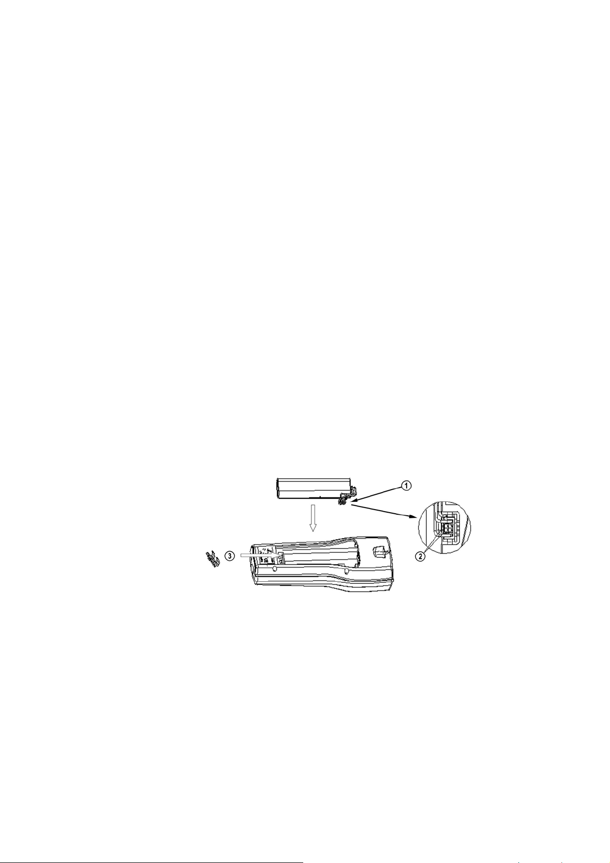
Chapter 12 ________________________________________________ Maintenance
Changing the Battery Pack
New rechargeable battery packs can be ordered from
Vaisala. Change the battery pack as follows:
1. Open the back plate of the indicator by opening the
screw of the back plate.
2. Remove the old battery pack. Detach the black
connector by pulling up carefully from the wires.
3. Connect the black connector of the new battery pack,
ensure that the position of the connector is as indicated
in Figure 4 (red and black wires are on the upper edge
of the connector). Do not push the connector with
conducting material
4. Place the battery pack, close the back plate and tighten
the screw.
5. Charge the battery pack before use, see page
17.
In case you are installing the battery pack and you have a
device with alkaline batteries, remove the metal contact
before installing the battery pack.
0505-239
Figure 19 Installing the Battery Pack
VAISALA _________________________________________________________ 61
Page 64

User's Guide_________________________________________________________
Technical Support
For technical questions, contact the Vaisala technical
support:
E-mail
Phone (int.) +358 9 8949 2789
Fax +358 9 8949 2790
helpdesk@vaisala.com
Return Instructions
If the product needs repair, please follow the instructions
below to speed up the process and avoid extra costs.
1. Read the warranty information.
2. Write a Problem Report with the name and contact
information of a technically competent person who can
provide further information on the problem.
3. On the Problem Report, please explain:
- What failed (what worked / did not work)?
- Where did it fail (location and environment)?
- When did it fail (date, immediately / after a while /
periodically / randomly)?
- How many failed (only one defect / other same or
similar defects / several failures in one unit)?
- What was connected to the product and to which
connectors?
- Input power source type, voltage and list of other
items (lighting, heaters, motors etc.) that were
connected to the same power output.
- What was done when the failure was noticed?
62 _____________________________________________________ M010139EN-D
Page 65
Chapter 12 ________________________________________________ Maintenance
4. Include a detailed return address with your preferred
shipping method on the Problem Report.
5. Pack the faulty product using an ESD protection bag of
good quality with proper cushioning material in a
strong box of adequate size. Please include the
Problem Report in the same box.
6. Send the box to:
Vaisala Oyj
Contact person / Division
Vanha Nurmijärventie 21
FIN-01670 Vantaa
Finland
or to the addresses
Vaisala Service Centers
below:
VAISALA _________________________________________________________ 63
Page 66

User's Guide_________________________________________________________
This page intentionally left blank.
64 _____________________________________________________ M010139EN-D
Page 67
Chapter 13 _______________________________________ Technical Specifications
CHAPTER 13
TECHNICAL SPECIFICATIONS
GM70 Hand-Held Carbon Dioxide Meter
General
Table 3 General Specifications
Property Description / Value
Storage temperature -30...+70°C
Storage humidity
range
0...100%RH non-condensing
Electromagnetic Compatibility
Complies with the following standard:
EN61326-1:1997+ Am1:1998 + Am2:2001, Electrical
equipment for measurement, control and laboratory use EMC requirements; Generic environment.
VAISALA _________________________________________________________ 65
Page 68
User's Guide_________________________________________________________
GMP221/222 Probes
Table 4 Measuring Ranges
Probe Measuring Ranges
GMP221 0...2%, 0...3%, 0...5%, 0...10%,
0...20%
GMP222 0...2000 ppm, 0...3000 ppm, 0...5000
ppm, 0...7000 ppm, 0...10000 ppm
Table 5 Accuracy Specifications
Accuracy at 25°C against certified factory references
(including repeatability and calibration uncertainty)
Probe Accuracy
GMP221
Accuracy specification applies for
CO
concentrations above 2% of
2
FS
GMP222 <±[20 ppm CO2 + 2% of reading]
Property Description / Value
Nonlinearity <±1%FS
Temperature
dependence
Pressure dependence 0.15% of reading/hPa (reference 1013
Long-term instability <±5%FS / 2 years
Response time (63%) 20 seconds (GMP221)
<±[0.02% CO2 + 2% of reading]
0.1%FS/°C (reference 25ºC/77ºF)
hPa)
30 seconds (GMP222)
Table 6 Other Specifications
Property Description / Value
Warm-up time
with GM70PUMP
Operation temperature -20...+ 60ºC
Operation pressure 700...1300 hPa
Operation humidity 0...100%RH non-condensing
Probe material PC
Probe cable length 1.9 m
30 seconds
15 min full specification
30 min full specification
66 _____________________________________________________ M010139EN-D
Page 69
Chapter 13 _______________________________________ Technical Specifications
GMH70 Handle, GM70PUMP
Table 7 General Specifications
Property Description / Value
GMH70 Handle
GMH70 handle
material
Probe fastener Aluminium
GM70PUMP
Pump housing Anodized aluminium/IP54
Pump 0...18 mbar differential pressure
Weight 0.7 kg
ABS/PC-blend
MI70 Indicator
Indicator General
Table 8 General Specifications
Property Description / Value
Operating temperature
range
Operating humidity
change
Menu languages English, German, French, Finnish,
Display LCD with backlight
Probe inputs 1 or 2
Power supply Rechargeable NIMH battery pack with
Analog output 0...1 VDC
Output resolution 0.6 mV
Accuracy 0.2% full scale
Temperature
dependence
Minimum load resistor 10 kohm to ground
Data interface RS232C
Data logging capacity 900...2700 real time data points
Logging interval 1 s to 12 h
Alarm Audible alarm function
Housing classification IP54
Weight 400 g
Housing material ABS/PC-blend
-10...+ 40ºC
0...100%RH non-condensing
Spanish and Swedish
Graphic trend display of any quantity
Character height up to 16mm
AC-POWER or 4 x AA size alkalines,
type IEC LR6
0.002%/°C full scale
VAISALA _________________________________________________________ 67
Page 70
User's Guide_________________________________________________________
Battery Pack
Table 9 Battery Pack Specifications
Property Description / Value
Operation times
continuous use (one
probe)
data logging use (one
probe)
when pump is on
Power consumption
during charge
Charging time 4 hour typical
8 h typical at +20°C
up to 30 days (1-hour measurement
interval)
5 h typical
10 W max
Accessories
Table 10 Accessories Table
Description Order Code
Euro AC-adapter MI70EUROADAPTER
UK AC-adapter MI70UKADAPTER
US AC-adapter MI70USADAPTER
AUS AC-adapter MI70AUSADAPTER
Measurement indicator
(battery pack included)
MI70 Link- software interface
kit
Analog output signal cable 27168ZZ
Connection cable for GM20series
Carrying case MI70CASE
Spare probe (use the order
form to define measurement
range)
Aspiration pump GM70PUMP
Handle GMH70
Spare filter for GMP221 25378GMSP
Spare filter for GMP222 25879GMSP
Field check adapter 26150GM
MI70
MI70LINK
GMA70
GMP221, GMP222
68 _____________________________________________________ M010139EN-D
Page 71
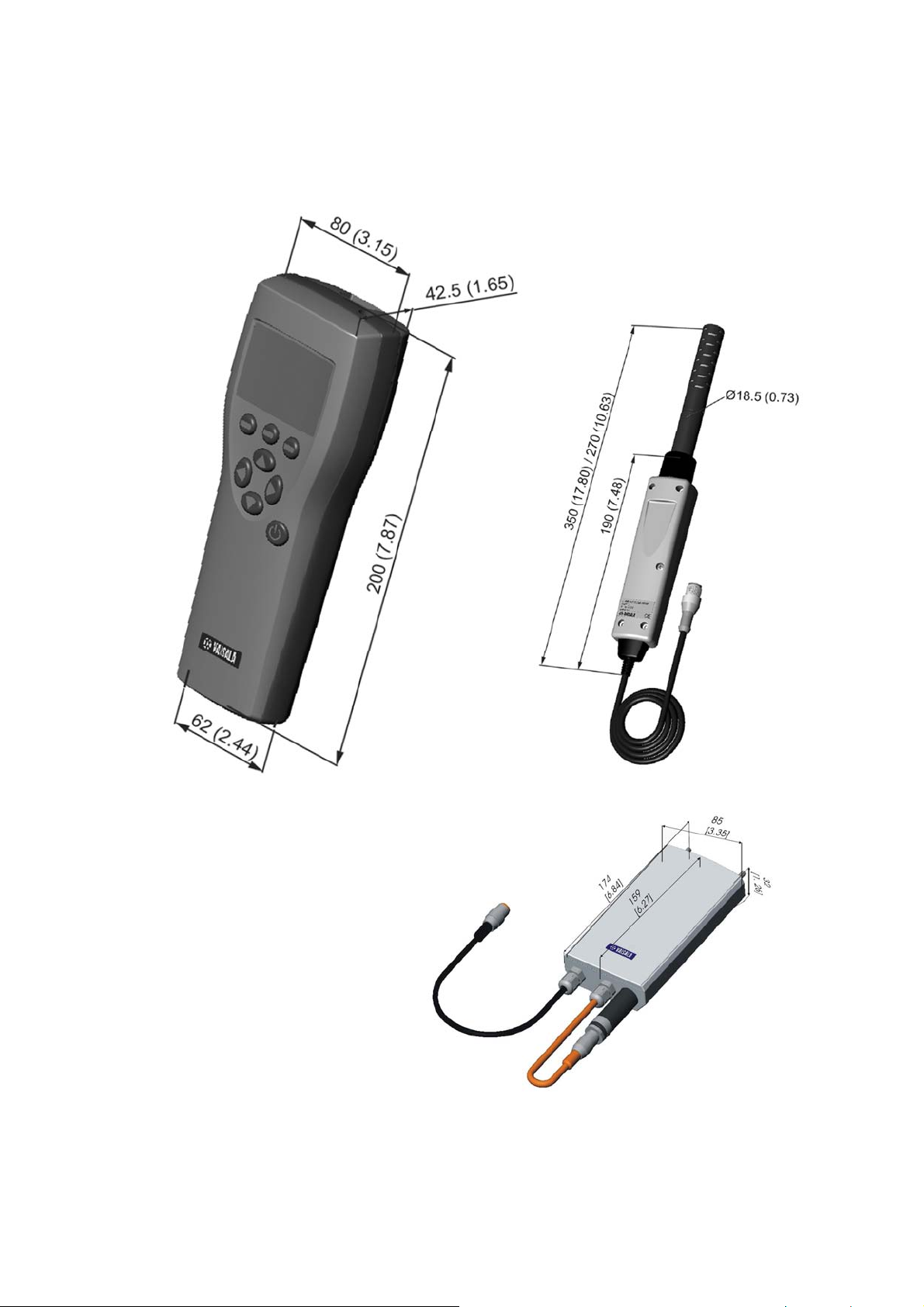
Chapter 13 _______________________________________ Technical Specifications
Dimensions in mm (inch)
0505-240
Figure 20 Dimensions
VAISALA _________________________________________________________ 69
Page 72

Page 73

Page 74

www.vaisala.com
 Loading...