

Page 1

M212242EN-C
Installation Guide
CMS Industrial Cabinet
AB100
C
Page 2

PUBLISHED BY
Vaisala Oyj
Vanha Nurmijärventie 21, FI-01670 Vantaa, Finland
P.O. Box 26, FI-00421 Helsinki, Finland
+358 9 8949 1
Visit our Internet pages at w
© Vaisala 2020
No part of this document may be reproduced,
published or publicly displa
any means, electronic or mechanical (including
photocopying), nor may its contents be modified,
translated, adapted, sold or disclosed to a third
party without prior written permission of the
copyright holder. Translated documents and
translated portions of multilingual documents are
based on the original English versions. In
ambiguous cases, the English versions are
applicable, not the translations.
The contents of this document are subject to
change without prior notice.
Local rules and regulations may vary and they
shall take precedence over the information
contained in this document. Vaisala makes no
representations on this document’s compliance
ww.vaisala.com.
yed in any form or by
with the local rules and regulations applicable at
an
y given time, and hereby disclaims any and all
responsibilities related thereto.
This document does not create any legally
binding obligations for Vaisala towards customers
or end users. All legally binding obligations and
agreements are included exclusively in the
applicable supply contract or the General
Conditions of Sale and General Conditions of
Service of Vaisala.
This product contains software developed by
Vaisala or third parties. Use of the software is
governed by license terms and conditions
included in the applicable supply contract or, in
the absence of separate license terms and
conditions, by the General License Conditions of
Vaisala Group.
Page 3

Table of contents
Table of contents
1. About this document.......................................................................................
1.1 Version information.............................................................................................5
1.2 Related manuals.................................................................................................. 5
1.3 Documentation conventions..............................................................................6
1.4 Trademarks........................................................................................................... 7
2. Product overview.............................................................................................. 8
2.1 Overview of Vaisala CMS Industrial Cabinet CAB100..................................... 8
2.2 Basic features and options.................................................................................9
2.2.1 CAB100A models........................................................................................ 10
2.2.2 CAB100B models.........................................................................................10
2.3 Physical structure and components..................................................................11
2.3.1 Enclosures.................................................................................................... 14
2.4 Regulatory compliances....................................................................................15
3. Installing the enclosure................................................................................. 16
3.1 Installing CAB100A with mounting frame...................................................... 16
3.2 Installing CAB100B with mounting frame.......................................................19
3.3 Enclosure flanges..............................................................................................23
3.3.1 Leading cables through rubber flange.................................................... 24
3.3.2 Leading cables through stainless steel flange........................................ 25
4. Electrical installation..................................................................................... 27
4.1 Installation safety.............................................................................................. 27
4.1.1 ESD protection............................................................................................ 28
4.2 Connecting AC (mains) power........................................................................ 28
4.3 Connecting power over Ethernet to CAB100A..............................................32
4.4 Supplying power to external measurement device from CAB100B........... 32
5
5. Adding devices to CAB100A..................................................................... 35
5.1 Expanding PDT101 transmitter installation in CAB100A.............................. 35
5.2 Expanding safety barrier installation in CAB100A........................................38
5.3 Expanding galvanic isolator installation in CAB100A................................... 41
6. Adding devices to CAB100B..................................................................... 44
6.1 Adding PDT101 transmitters as new modules to CAB100B.........................44
6.2 Expanding PDT101 transmitter installation in CAB100B.............................. 50
6.3 Adding analog input channels to CAB100B.................................................. 56
6.3.1 Wiring and powering loop-powered measurement devices.................62
6.3.2 Wiring externally powered measurement devices.................................65
6.4 Adding safety barriers as new modules to CAB100B.................................. 69
6.5 Expanding safety barrier installation in CAB100B........................................78
6.6 Adding galvanic isolators as new modules to CAB100B............................. 85
6.7 Expanding galvanic isolator installation in CAB100B...................................93
6.8 Installing serial port server and Ethernet switch........................................ 100
7. Replacing devices.........................................................................................105
7.1 Replacing PDT101 transmitters in CAB100A and CAB100B.......................105
7.2 Replacing DL4000 data loggers in CAB100A and CAB100B....................109
8. Maintenance..................................................................................................... 114
8.1 PDT101 calibration............................................................................................ 114
8.2 PDT101 adjustment........................................................................................... 114
8.3 Cleaning.............................................................................................................115
1
Page 4

CAB100 Installation Guide M212242EN-C
9. Technical data..................................................................................................
116
9.1 CAB100 specifications..................................................................................... 116
9.1.1 Enclosure dimensions................................................................................118
9.2 Component specifications...............................................................................119
9.2.1 Vaisala Dierential Pressure Transmitter PDT101 specifications.......... 119
9.2.2 Vaisala DL4000 Universal Data Logger specifications......................... 121
9.2.3 Vaisala vNet PoE Data Logger Interface specifications....................... 123
9.2.4 Third-party component specifications................................................... 125
9.3 Spare parts and accessories...........................................................................126
Appendix A: Wiring diagrams.....................................................................128
A.1 CAB100A wiring diagrams.............................................................................
128
A.2 CAB100B wiring diagrams..............................................................................133
Appendix B: Layout diagrams.....................................................................138
B.1 CAB100A layout diagrams............................................................................. 138
B.2 CAB100B layout diagrams............................................................................. 143
Appendix C: Removing and recycling data logger battery.................149
Maintenance and calibration services........................................................ 151
Warranty............................................................................................................ 151
Technical support............................................................................................ 151
Recycling........................................................................................................... 151
2
Page 5

List of figur
es
List of figur
Figure 1 Cabinet models CAB100A (small) and CAB100B (large)........................ 8
Figure 2 Main components inside CAB100A, PDT101 model with
Figure 3 Main components inside CAB100A, PDT101 model with vNet PoE......12
Figure 4 Main components inside CAB100B, mixed model with
Figure 5 CAB100A enclosure dimensions................................................................... 14
Figure 6 CAB100B enclosure dimensions....................................................................14
Figure 7 CAB100A wall installation accessories........................................................ 17
Figure 8 CAB100B wall installation accessories.........................................................21
Figure 9 Stainless steel flange........................................................................................25
Figure 10 CAB100A enclosure dimensions..................................................................118
Figure 11 CAB100B enclosure dimensions.................................................................. 119
Figure 12 Wiring diagram for CAB100A PDT101 voltage model with
Figure 13 Wiring diagram for CAB100A PDT101 voltage model with
Figure 14 Wiring diagram for CAB100A analog channel model with
Figure 15 Wiring diagram for CAB100A safety barrier model with
Figure 16 Wiring diagram for CAB100A galvanic isolator model with
Figure 17 Wiring diagram for CAB100B PDT101 model...........................................133
Figure 18 Wiring diagram for CAB100B analog channel model with
Figure 19 Wiring diagram for CAB100B analog channel model with
Figure 20 Wiring diagram for CAB100B safety barrier model...............................136
Figure 21 Wiring diagram for CAB100B galvanic isolator model......................... 137
Figure 22 Main components inside CAB100A, PDT101 model with
Figure 23 Main components inside CAB100A, PDT101 model with vNet PoE...139
Figure 24 Main components inside CAB100A, analog channel model
Figure 25 Main components inside CAB100A, safety barrier model
Figure 26 Main components inside CAB100A, galvanic isolator
Figure 27 Main components inside CAB100B, mixed model with
Figure 28 Main components inside CAB100B, PDT101 model............................... 144
Figure 29 Main components inside CAB100B, analog channel model................145
Figure 30 Main components inside CAB100B, mixed model with
Figure 31 Main components inside CAB100B, safety barrier model....................147
Figure 32 Main components inside CAB100B, galvanic isolator model..............148
es
serial port serv
PDT101s, analog input channels, and safety barriers...............................13
serial port server and 24 VDC power supply........................................... 128
vNet PoE............................................................................................................ 129
serial port server and 24 VDC power supply...........................................130
serial port server and 24 VDC power supply............................................ 131
serial port server and 24 VDC power supply........................................... 132
loop-powered measurement devices........................................................134
externally powered measurement devices...............................................135
serial port server and 24 VDC power supply........................................... 138
with serial port server and 24 VDC power supply................................. 140
with serial port server and 24 VDC power supply.................................. 141
model with serial port server and 24 VDC power supply.................... 142
PDT101s, analog input channels, and safety barriers.............................143
PDT101s and safety barriers..........................................................................146
er and 24 VDC power supply..............................................11
3
Page 6

CAB100 Installation Guide M212242EN-C
List of tables
Table 1 Document versions (English).............................................................................5
Table 2 Related manuals.................................................................................................... 5
Table 3 CAB100 c
Table 4 Enclosure flanges and recommended use...................................................23
Table 5 CAB100 operating environment.................................................................... 116
Table 6 CAB100 powering specifications...................................................................116
Table 7 CAB100 mechanical specifications............................................................... 116
Table 8 CAB100 environmental compliance..............................................................117
Table 9 CAB100 EMC compliance.................................................................................118
Table 10 PDT101 models.................................................................................................... 119
Table 11 PDT101 measurement performance.............................................................. 119
Table 12 PDT101 operating environment..................................................................... 120
Table 13 PDT101 compliance...........................................................................................120
Table 14 PDT101 inputs and outputs...............................................................................121
Table 15 PDT101 mechanical specifications..................................................................121
Table 16 DL4000 general specifications...................................................................... 121
Table 17 DL4000 memory specifications....................................................................122
Table 18 DL4000 recording span.................................................................................. 123
Table 19 DL4000 current loop and voltage inputs...................................................123
Table 20 vNet operating environment..........................................................................123
Table 21 vNet inputs and outputs..................................................................................123
Table 22 vNet mechanical specifications.....................................................................124
Table 23 vNet general specifications............................................................................ 124
Table 24 Power supply module product information...............................................125
Table 25 Circuit breaker product information.............................................................125
Table 26 Safety barrier product information.............................................................. 125
Table 27 Galvanic isolator product information.........................................................125
Table 28 Serial port server product information........................................................126
Table 29 Ethernet switch product information.......................................................... 126
Table 30 CAB100 spare parts and accessories...........................................................126
onfiguration options..........................................................................9
4
Page 7

1. About this document
Version information
1.1
Chapter 1 – About this document
This document provides installation instructions and product specifica
Industrial Cabinet CAB100.
Table 1 Document versions (English)
Document code Date Description
M212242EN-C December 2020 New chapters in this revision:
• Supplying po
(page 32)
• Wiring externally powered measurement devices (page 65)
Updated chapters:
• Wiring and powering loop-powered measurement devices
(page 62)
• Vaisala Dierential Pressure Transmitter PDT101 specifications
(page 119)
• CAB100B wiring diagrams (page 133) (wiring diagram for externally
powered devices added)
M212242EN-B June 2020 New chapters in this revision:
•
All chapters describing the small cabinet model CAB100A
• Enclosure flanges (page 23)
Updated chapters:
• Installation safety (page 27)
• Installing serial port server and Ethernet switch (page 100)
• Spare parts and accessories (page 126)
wer to external measurement device from CAB100B
tions for Vaisala CMS
M212242EN-A October 2019 First version.
1.2 Related manuals
Table 2 Related manuals
Document code Name
M212262EN Vaisala CMS Industrial Cabinet CAB100 Assembling Analog Channel Terminal Block
T
echnical Note
M212294EN Vaisala CMS Industrial Cabinet CAB100 Wiring Diagrams Technical Reference
M212284EN Vaisala CMS Industrial Cabinet CAB100 Quick Guide
M211284EN Vaisala Dier
M211247EN Vaisala HUMICAP
ential Pressure Transmitter PDT101 Quick Guide
â
Humidity and Temperature Transmitter Series HMT120 Quick Guide
5
Page 8

CAB100 Installation Guide M212242EN-C
Document code Name
M211244EN Vaisala HUMICAP
M210566EN Vaisala HUMICAP
M010056EN Vaisala HUMICAP
M210483EN Vaisala Transmitter Series HMT360 Safety Guide
M211975EN Vaisala viewLinc Enterprise Server Version 5.0 User Guide
M211655EN Vaisala vNet PoE Network Interface Quick Start Guide
M211700EN Vaisala vNet PoE Network Interface User's Guide
90000687-88 DIGI PortServer
158962 / 900260
2300
S-SM-9160-06-
/2015
en-09
Stahl 9001 Series Single-channel Safety Barrier Operating Instructions
Stahl Type 9160/9163 Transmitter Supply Unit/Isolating Repeater Safety Manual
â
Humidity and Temperature Transmitter Series HMT120 User Guide
â
Humidity and Temperature Transmitter Series HMT330 User Guide
â
Humidity and Temperature Transmitter Series HMT360 User's Guide
â
TS Family Quick Start Guide
Documentation by third-party instrument manufacturers is provided as is.
1.3 Documentation conventions
WARNING!
Warning alerts y
instructions carefully at this point, there is a risk of injury or even death.
CAUTION!
Caution warns you of a potential hazard. If you do not read and follow
instructions carefully at this point, the product could be damaged or important data
could be lost.
Note highligh
Tip giv
ts important information on using the product.
es information for using the product more eciently.
ou to a serious hazard. If you do not read and follow
6
Page 9

Lists tools needed to perform the task.
Indicates that you need to take some notes during the task.
1.4 Trademarks
Chapter 1 – About this document
Vaisalaâ is a r
HUMICAPâ is a registered trademark of Vaisala Oyj.
DIGI PortServerâ is a registered trademark of DIGI International Inc.
All other product or company names that may be mentioned in this publication are trade
names, trademarks, or registered trademarks of their respective owners.
egistered trademark of Vaisala Oyj.
7
Page 10

CAB100 Installation Guide M212242EN-C
2. Product overview
2.1 Overview of Vaisala CMS Industrial
Cabinet C
Vaisala CMS Industrial Cabinet CAB100 is an instrument cabinet designed to integrate
de
vices for measuring humidity, temperature, dierential pressure, and other parameters.
Combined with the Vaisala viewLinc Continuous Monitoring System, CAB100 is an
integrated solution for real-time monitoring of cleanrooms and industrial applications in
multiple industries.
CAB100 is available in 2 models, CAB100A (small enclosure) and CAB100B (large enclosure).
The cabinets can be configured according to application requirements, with options for
dierential pressure transmitters, analog input channels for the connection of remote
transmitters, and safety barriers or galvanic isolators for hazardous areas, used with
intrinsically safe devices.
AB100
Figure 1 Cabinet models CAB100A (small) and CAB100B (large)
8
Page 11
2.2 Basic features and options
Chapter 2 – Product overview
Table 3 CAB100 c
Property Description/Value
Cabinet size
(H × W × L
Powering Power supply:
Dierential pr
Analog input channels 4 ... 32 channels, 4 ... 20 mA
Safety barrier 1 ... 16 pcs, 1 barrier per channel
Galvanic isolator 1 ... 12 pcs, 1 isolator per channel
Ethernet communication CAB100A: Vaisala vNet Power over Ethernet Data Logger Interface, with PoE
Ethernet Ethernet switch, +4 PoE IEEE 802.3af/at
Standards
)
onfiguration options
CAB100A: 200 × 300 × 400 mm (7.87 × 11.81 × 15.75 in)
CAB100B: 200 × 500 × 600 mm (7.87 × 19.69 × 23.62 in)
•
Within cabinet: 24 VDC / 2.5 A
• To cabinet: 110 ... 240 VAC
Power over Ethernet (with loop power, without fan)
essure 1 ... 12 pcs, ±60 Pa or ±0.25 in H2O
option via R
CAB100B: Up to 2 serial-to-Ethernet devices via RJ45 (DIGI PortServer TS4)
EN/IEC61326-1 (Basic electromagnetic environment)
EN5
5032 Class B
IEC/UL/EN 61010-1
IP66/NEMA 4 (CAB100B) / IP54 (CAB100A)
Safety listed in USA and Canada
J45 connector
3)
1)
2)
4)
1) PoE is available for CAB100A PDT101 model only.
Excluding CAB100 analog input channels, which are not surge protected.
2)
3) UL listing pending.
4) Safety listing pending.
More information
‣
C
AB100 specifications (page 116)
‣
Component specifications (page 119)
‣
Spare parts and accessories (page 126)
9
Page 12

CAB100 Installation Guide M212242EN-C
2.2.1 CAB100A models
CAB100A is available in 4 pr
e-configured models. There are 2 communication interface
options for CAB100A: serial port server (for all models) or the Vaisala vNet PoE data logger
interface (option for PDT101 model only).
CAB100A model Maximum number of measurement devices per model
PDT101 model 4 PDT101 transmitters
Analog channel model 4 analog input channels
Safety barrier model 4 safety barriers
Galvanic isolator model 4 galvanic isolators
More information
‣
C
AB100A layout diagrams (page 138)
2.2.2 CAB100B models
CAB100B is available in 4 pr
CAB100B models is a multiport serial port server.
CAB100B model Maximum number of measurement devices per model
e-configured models. The communication interface in all
PDT101 model 16 PDT101 transmitters
Analog channel model 32 analog input channels
Safety barrier model 16 safety barriers
Galvanic isolator model 12 galvanic isolators
In addition to the above, mixed CAB100B models are available, with limitations. Contact
your Vaisala sales representative for details. For an example configuration, see Figure 4
(page 13).
More information
‣
CAB100B layout diagrams (page 143)
10
Page 13
1
5
6
4
7
8
3
910
2
Chapter 2 – Product overview
2.3 Physical structure and components
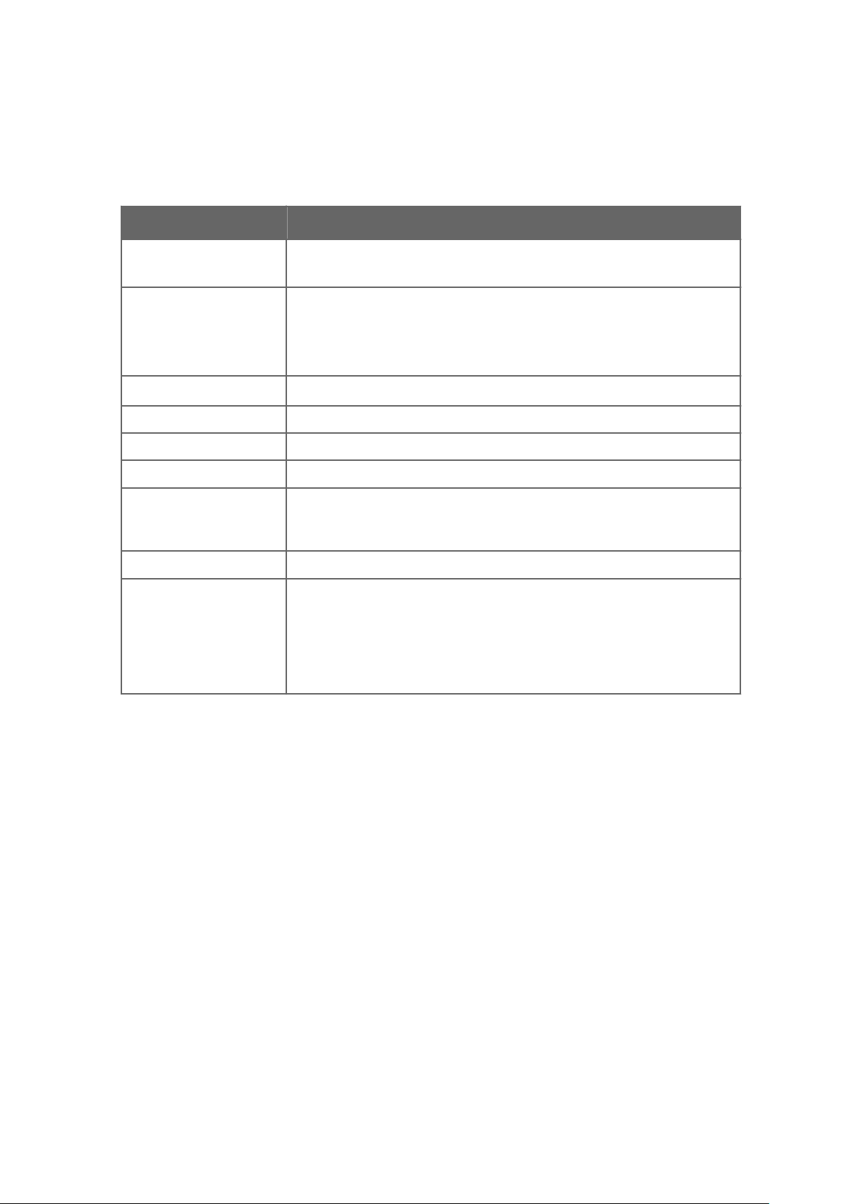
Figure 2 Main components inside CAB100A, PDT101 model with serial port server and 24 VDC
wer supply
po
1 Mounting clamp for DL4000 data logger
2 DL4000 data logger
3 PDT101 transmitters (4 pcs)
4 Cover plate
5 24 VDC fuses T2.5A, 5 × 20 mm (2 pcs)
6 110 … 240 VAC mains input and grounding point (under cover plate)
7 Circuit breaker and power supply module
8 Grounding terminal block
9 Serial port server
10 Mounting clamp for serial port server
11
Page 14
1
3
2
5
4
CAB100 Installation Guide M212242EN-C
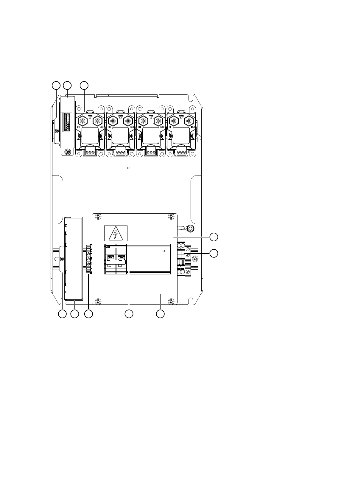
Figure 3 Main components inside CAB100A, PDT101 model with vNet PoE
1 PDT101 transmitters (4 pcs)
2 vNet PoE data logger interface
3 DL4000 data logger
4 Protective label. R
emove before installation.
5 Grounding terminal block
12
Page 15
5
6
1
7
9
10
12
16
4
8
2
3
14
11
13
15
Chapter 2 – Product overview
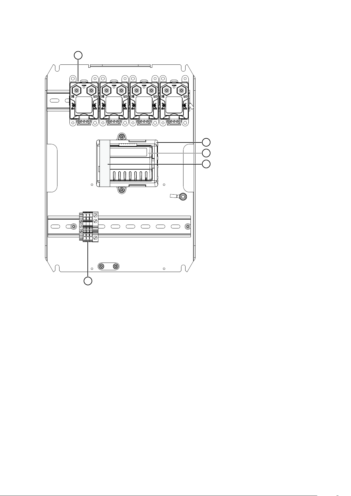
Figure 4 Main components inside CAB100B, mixed model with PDT101s, analog input channels,
and saf
1 Cable duct for intrinsically safe connections
ety barriers
2 Safety barriers (8 pcs)
3 Terminal block for analog input channels
4 Holders for tubing (3 pcs)
5 PDT101 transmitters (4 pcs)
6 DL4000 data loggers (6 pcs)
7 Serial port servers (2 pcs)
8 Ethernet switch
9 24 VDC power block
10 24 VDC fuses T2.5A, 5 × 20 mm (2 pcs)
11 Cover plate
12 Circuit breaker and power supply module
13 110 … 240 VAC mains input (under cover plate)
14 Cable strain relief
15 Grounding terminal block
16 Partition plate separating intrinsically safe and non-intrinsically safe connections
13
Page 16

400 [15.74]
207.6 [8.17]
202.1 [7.96]
300 [11.81]
418 [16.5]
mm
[in]
600 [23.62]
500 [19.69]
206 [8.11]
618 [24.33]
mm
[in]
CAB100 Installation Guide M212242EN-C
For more layout diagrams of CAB100 c
diagrams (page 138) and CAB100B layout diagrams (page 143).
2.3.1 Enclosures
Figure 5 CAB100A enclosure dimensions
onfiguration options, see CAB100A layout
Figure 6 CAB100B enclosure dimensions
The CAB100A enclosure is made of aluminium, and has IP54 rating. The CAB100B enclosure
is made of stainless steel, and has IP66/NEMA 4 rating.
1) The IP ratings apply only when using the factory-installed top and bottom flanges in the enclosures.
14
1)
Page 17

800226
Chapter 2 – Product overview
There are flanges f
or cable lead-through on the top and bottom of the enclosures. The top
flange of both small and large cabinet is made of rubber. Stainless steel and rubber flange
models are available to order for the bottom of the cabinet.
The enclosures come with a mounting frame for easy installation.
More information
‣
Installing CAB100A with mounting frame (page 16)
‣
Installing CAB100B with mounting frame (page 19)
‣
Enclosure flanges (page 23)
‣
CAB100 specifications (page 116)
2.4 Regulatory compliances
This product complies with the following electromagnetic compatibility and safety
s
tandards:
• EN/IEC 61326‑1: Basic electromagnetic environment.2) EN 55032 Class B.
• EN/UL/IEC 61010‑1: Safety requirements for electrical equipment for measurement,
control, and laboratory Use – Part 1: General requirements.
2) Excluding CAB100 analog input channels, which are not surge protected.
15
Page 18

CAB100 Installation Guide M212242EN-C
3. Installing the enclosure
Installing CAB100A with mounting
3.1
frame
• 4‑mm Allen k
• 10-mm wrench
• Drill and 8-mm drill bits for making the installation holes
• Spirit level
CAUTION!
requires at least 2 people.
CAUTION!
f
ollowing:
• The analog input channel wiring must not exceed 30 meters.
• The wiring must not come from outside the building where CAB100 is installed.
If CAB100 cannot be installed in an environment that meets the above criteria, use a
suitable surge protection device that has been installed following local regulations.
CAUTION!
damage the equipmen
ey
For safety reasons, do not carry out installations alone. Safe installation
CAB100 analog input channels are not surge protected. Therefore, note the
Do not drill holes in the backplate or the enclosure. Drill shavings may
t inside the cabinet.
CAB100 is shipped with a mounting frame and installation accessories for indoor wall
ins
tallation. If the screws delivered with the mounting frame are not suitable for the wall
material in the installation location, use any appropriate screws to attach the frame.
16
Page 19

4
1
3
2
200 [7.9]
300 [12]
Ø
8 [0.31]
mm
[in]
Chapter 3 – Installing the enclosure
Figure 7 CAB100A wall installation accessories
1 Hole for wall plug (4 pcs)
2 Mounting slot (2 pcs)
3 Wall plug (4 pcs)
4 Hex wood screw M6×40 DIN571 A2 (4 pcs)
1. Drill holes into the wall. Use the mounting frame as a guide.
Place the wall plugs into the drilled holes.
2.
17
Page 20

CAB100 Installation Guide M212242EN-C
3. Attach the mounting frame to the wall with screws.
4. Lift the enclosure into place.
Hang the enclosur
e onto the frame by sliding the mounting studs on the back of the
enclosure into the mounting slots of the frame.
18
Page 21

5. Attach the bottom of the enclosure to the mounting frame.
1
2
Chapter 3 – Installing the enclosure
1 Washer with EPDM gasket 6.8/16×1.5/A2/EPDM (2 pcs)
2 Hex screw M6×16 ISO7380 A4 (2 pcs)
3.2 Installing CAB100B with mounting
ame
fr
• 4‑mm Allen k
• 10-mm wrench
• Drill and 8-mm drill bits for making the installation holes
• Spirit level
CAUTION!
r
equires at least 2 people.
ey
For safety reasons, do not carry out installations alone. Safe installation
19
Page 22

CAB100 Installation Guide M212242EN-C
CAUTION!
ollowing:
f
• The analog input channel wiring must not exceed 30 meters.
• The wiring must not come from outside the building where CAB100 is installed.
If CAB100 cannot be installed in an environment that meets the above criteria, use a
suitable surge protection device that has been installed following local regulations.
CAUTION!
damage the equipmen
CAB100 analog input channels are not surge protected. Therefore, note the
Do not drill holes in the backplate or the enclosure. Drill shavings may
t inside the cabinet.
CAB100 is shipped with a mounting frame and installation accessories for indoor wall
tallation. If the screws delivered with the mounting frame are not suitable for the wall
ins
material in the installation location, use any appropriate screws to attach the frame.
20
Page 23

175 [6.9]
175 [6.9]
440 [17.3]
Ø
8 [0.31]
4
1
3
2
mm
[in]
Chapter 3 – Installing the enclosure
Figure 8 CAB100B wall installation accessories
1 Hole for wall plug (4 pcs)
2 Wall plug (4 pcs)
3 Mounting slot (2 pcs)
4 Hex wood screw M6×40 DIN571 A2 (4 pcs)
1. Drill holes into the wall. Use the mounting frame as a guide.
Place the wall plugs into the drilled holes.
2.
21
Page 24

CAB100 Installation Guide M212242EN-C
3. Attach the mounting frame to the wall with screws.
4. Lift the enclosure into place.
Hang the enclosur
e onto the frame by sliding the mounting studs on the back of the
enclosure into the mounting slots of the frame.
22
Page 25

5. Attach the bottom of the enclosure to the mounting frame.
1
2
Chapter 3 – Installing the enclosure
1 Washer with EPDM gasket 6.8/16×1.5/A2/EPDM (2 pcs)
2 Hex screw M6×16 ISO7380 A4 (2 pcs)
3.3 Enclosure flanges
Vaisala recommends that you lead cables, wires, and tubes into the CAB100 enclosure
thr
ough the top and bottom flanges as explained in Table 4 (page 23).
Table 4 Enclosure flanges and r
Number and type of flanges per
c
abinet model
CAB100A:
•
1 flange on the top and
1 on the bottom of the
enclosure
• Top flange is made of rubber.
Rubber or stainless steel flange
is available to order for the
bottom.
ecommended use
Type of connection Recommended flange to
use
AC (mains) cable Top flange
Tubes for PDT101 transmitters
E
thernet PoE cable
Wires for safety barriers, galvanic isolators,
and external measurement devices
Bottom flange
23
Page 26

2
1
CAB100 Installation Guide M212242EN-C
Number and type of flanges per
abinet model
c
CAB100B:
•
2 flanges on the top and
2 on the bottom of the
enclosure
• Top flanges are made of
rubber. Rubber or stainless
steel flanges are available to
order for the bottom.
Type of connection Recommended flange to
Tubes for PDT101 transmitters
Wires for external measurement devices
AC (mains) cable Bottom right-hand flange
Wires for safety barriers and galvanic
isola
tors
3.3.1 Leading cables through rubber flange
CAUTION!
through the flanges as instructed.
• Pipette
•
Wire cutters
• Wire-stripping pliers
To preserve the IP rating of the enclosure, make sure that you lead cables
use
Top flange
Bottom left-hand flange
only
1. Lead the cables into the enclosure using the pipette provided.
1 Cable
2 Pipette for leading the cable through the flange
2. Insert the pipette through one of the feed-through rondels in the flange
.
3. Insert a cable and pull it through to the inside.
4. Inside the enclosure, connect the cables and wires according to the wiring diagram.
24
Page 27

1 2 3 4 5
Chapter 3 – Installing the enclosure
CAUTION!
es properly. Too much strain may cause the cable or wire to fall o or damage the
wir
cable, wire, or connector.
To avoid strain on the connector, make sure that you connect cables and
More information
‣
Ins
tallation safety (page 27)
‣
Connecting AC (mains) power (page 28)
‣
Wiring diagrams (page 128)
‣
Layout diagrams (page 138)
3.3.2 Leading cables through stainless steel flange
CAUTION!
thr
ough the flanges as instructed.
• Wire cutters
•
Wire-stripping pliers
To preserve the IP rating of the enclosure, make sure that you lead cables
Figure 9 Stainless steel flange
1 Flange
2 Cable gland, cable diameter 7.5 … 14 mm (0.30 … 0.55 in)
3 Dummy plug M16 × 1.5
4 Cable gland, cable diameter 5 … 10 mm (0.20 … 0.39 in)
5 Cable gland, cable diameter 3 … 6.5 mm (0.12 … 0.26 in)
1. Lead the cables through the cable glands in the flange.
25
Page 28

CAB100 Installation Guide M212242EN-C
2. RJ45 connectors do not fit thr
ough the cable glands. Cut o the existing connector,
lead the Ethernet cable through a cable gland, and attach a new cable connector to the
cable. For instructions, see the connector documentation.
3. Inside the enclosure, connect the cables and wires according to the wiring diagram.
CAUTION!
es properly. Too much strain may cause the cable or wire to fall o or damage the
wir
cable, wire, or connector.
To avoid strain on the connector, make sure that you connect cables and
More information
‣
Ins
tallation safety (page 27)
‣
Connecting AC (mains) power (page 28)
‣
Wiring diagrams (page 128)
‣
Layout diagrams (page 138)
26
Page 29

Chapter 4 – Electrical installation
4.
Electrical installation
4.1 Installation safety
WARNING!
adher
e to local and state legislation and regulations.
WARNING!
servic
eable parts inside the module. If the power supply module is faulty, replace it.
WARNING!
egulations at all times.
r
Only licensed experts may install electrical components. They must
Do not open the AC/DC power supply module. There are no user-
Keep away from live circuits. Operating personnel must observe safety
WARNING!
minimiz
WARNING!
some time
them.
CAUTION!
ollowing:
f
• The analog input channel wiring must not exceed 30 meters.
• The wiring must not come from outside the building where CAB100 is installed.
If CAB100 cannot be installed in an environment that meets the above criteria, use a
suitable surge protection device that has been installed following local regulations.
CAUTION!
cannot be loop-powered.
Ground the product and verify installation grounding periodically to
e shock hazard.
After disconnecting the power cable, dangerous voltages can exist for
. To avoid injury, disconnect the power and discharge circuits before touching
CAB100 analog input channels are not surge protected. Therefore, note the
Do not use the power block in CAB100 to power measurement devices that
27
Page 30

CAB100 Installation Guide M212242EN-C
CAUTION!
ety barriers or galvanic isolators, ensure that you comply with the safe work
saf
procedure outlined in IEC/EN 60079-14 and possible applicable local safety standards.
CAUTION!
oper modification may lead to safety hazards, equipment damage, failure to
Impr
perform according to specification, decreased equipment lifetime, or the warranty
becoming void.
CAUTION!
requires at least 2 people.
More information
‣
W
iring diagrams (page 128)
‣
Layout diagrams (page 138)
When working in explosion hazardous areas with installations involving
Do not modify the unit or use it in ways not described in the documentation.
For safety reasons, do not carry out installations alone. Safe installation
4.1.1 ESD protection
Electrostatic discharge (ESD) can cause immediate or latent damage to electronic circuits.
V
aisala products are adequately protected against ESD for their intended use. However, it is
possible to damage the product by delivering an electrostatic discharge when touching,
removing or inserting any objects inside the equipment housing.
Avoid touching component contacts or connectors when working with the device.
4.2 Connecting AC (mains) power
WARNING!
the main power source.
CAUTION!
Ins
tallation safety (page 27)
Before connecting the AC (mains) power cable, switch o the po
Before connecting power to the device, read carefully the safety notes in
wer from
28
Page 31

Chapter 4 – Electrical installation
• Screwdriver
Wire cutters
•
• Wire-stripping pliers
For the AC (mains) power connection, you need an external disconnection device (for
e
xample, a power cable or a mains power switch).
Note the following:
• The disconnection device must be rated 16 A or 20 A at 250 VAC, and must conform to
any additional local regulations.
• The disconnection device must be visible from the cabinet, or lockable with a key to
prevent accidental switching on during installation and maintenance.
• The cabinet must not block access to the disconnection device after it has been
installed. The disconnection device must remain easy to operate.
The AC (mains) cable is not included in the delivery. Use an AC (mains) cable with a
minimum cross-section of 3 × 0.75 mm2 (18 AWG).
Refer to La
yout diagrams (page 138) for the locations of components inside the cabinet.
1. Unscrew and remove the transparent cover plate protecting the circuit breaker and the
wer supply module.
po
2. Lead the AC (mains) cable into the enclosure.
Lead the cable through a flange in the cabinet enclosure, following relevant safety
regulations. Take note of safe areas around safety barriers or galvanic isolators inside
the enclosure.
29
Page 32

100 [3.94]
50 [1.97]
mm
[in]
1
2
3
CAB100 Installation Guide M212242EN-C
3. Strip approximately 100 mm (4 in) of the cable, and cut the phase and neutral wires to
the length of appr
oximately 50 mm (2 in). If you are using a stranded wire, add cable
ferrules to the ends.
CAUTION!
es. Under mechanical stress, the grounding wire must be the last to disconnect
wir
Make sure that the grounding wire is longer than the phase and neutral
from the protective ground terminal.
Number Wire Wire color
(in
ternational)
1 Phase L Brown Black Solid wire: 4 mm2 (12 A
2 Neutral N Blue White Solid wire: 4 mm2 (12 AWG)
Wire color (North
America)
Maximum wire cross-section
WG)
Stranded wire: 2.5 mm2 (14 A
WG)
3 Grounding
PE/
GND
Stranded wire: 2.5 mm2 (14 A
Yellow/Green Green Solid wire: 4 mm2 (12 AWG)
Stranded wire: 2.5 mm2 (14 A
WG)
WG)
30
Page 33

2
1
3
L N
Chapter 4 – Electrical installation
4. Connect the phase, neutral, and grounding wires of the AC (mains) cable as indicated in
the figur
e below.
1 Connect the (green or yellow-green) grounding wire to the grounding terminal
block.
2 Connect the phase (L) and neutral (N) wires to the circuit breaker: the phase in the
left
-hand screw terminal and the neutral in the right-hand screw terminal.
3 Mount the AC (mains) cable to the strain relief fixture located under the circuit
breaker.
5. Reattach the transparent cover plate.
6.
Switch on the circuit breaker.
7. Switch on mains power.
More information
‣
Wiring diagrams (page 128)
‣
Layout diagrams (page 138)
31
Page 34

CAB100 Installation Guide M212242EN-C
4.3
Connecting power over Ethernet to
CAB100A
CAUTION!
tallation safety (page 27).
Ins
1. In CAB100A PDT101 model with vNet PoE, power the cabinet by connecting your
thernet PoE cable to the vNet device.
E
Before connecting power to the device, read carefully the safety notes in
2. Switch on mains power.
User documentation for Vaisala vNet Power over Ethernet Data Logger Interface is
available in www.vaisala.com.
More information
‣
W
iring diagrams (page 128)
‣
Layout diagrams (page 138)
4.4 Supplying power to external
measur
Small screwdriver
ement device from CAB100B
CAUTION!
wiring instructions in the device-specific user documentation.
32
Before connecting any external measurement device to CAB100, refer to the
Page 35

Chapter 4 – Electrical installation
CAUTION!
wer block and the CAB100 analog terminal block.
po
Do not power an external measurement device both via the CAB100 24 VDC
You can use the 24 VDC power block in CAB100 for powering measurement devices that
equire external powering.
r
For instructions on powering loop-powered devices via the CAB100 analog terminal block,
see Wiring and powering loop-powered measurement devices (page 62).
To power an externally powered device from the CAB100B power block:
1. De-energize the cabinet: switch o mains power and the circuit breaker located inside
the cabinet.
1 Circuit breaker
2. Use the available connectors on the bottom row of the CAB100B power block for
c
onnecting the power wires of the external measurement device.
The power block is located on the right-hand side of the cabinet.
33
Page 36

2
1
CAB100 Installation Guide M212242EN-C
3. Connect the wires of the device in the same order as shown below: negative (black) on
the righ
t, with positive (red) on its left.
Do not disconnect the existing power wires on the bottom row.
1 Row available for power wires of external measurement devices
2 Power wires from the CAB100B power supply module. Do not disconnect.
CAUTION!
sensor pur
devices momentarily. When powering external devices, please make sure that the
additional power requirements do not exceed the capacity of the CAB100B power
supply. If in doubt, contact Vaisala for more information.
Some functionalities of external measurement devices (for example,
ge in Vaisala probes) may increase the power consumption of the
4. After connecting the power wires, reconnect power in the cabinet.
Switch on the circuit breaker.
a.
b. Switch on mains power.
More information
‣
Wiring diagrams (page 128)
‣
Layout diagrams (page 138)
34
Page 37

Chapter 5 – Adding devices to CAB100A
5. Adding devices to CAB100A
5.1 Expanding PDT101 transmitter
tallation in CAB100A
ins
• Small fla
Check the type of your PDT101 transmitters (voltage model / current model) before
dering new devices, as you cannot mix dierent types of PDT101 models in a cabinet
or
installation. For more information, see Spare parts and accessories (page 126).
Follow the steps below to add new PDT101 transmitters to an existing set of transmitters in
C
AB100A. Note the dierent steps for 24 VDC and PoE powered models.
Refer to CAB100A layout diagrams (page 138) when planning the installation.
1. Switch o mains power.
2. De-energize the existing PDT101 transmitters as shown below.
3. De-energizing 24 VDC powered CAB100A model:
Disconnect the PDT101 power wires from the fuse terminal blocks located at the righthand end of the power block.
t head screwdriver
35
Page 38

CAB100 Installation Guide M212242EN-C
4. De-energizing vNe
t PoE powered CAB100A model:
Disconnect the Ethernet PoE cable from the vNet device.
5. Mount the new PDT101 transmitter on the DIN rail.
est the upper part of the locking mechanism on the DIN rail and push down firmly.
R
This will click the device into place.
6. Use the existing wires in the PDT101 wire set to connect the new PDT101.
Discard the black wire end caps before connecting the wires.
7. Fasten the wires to the screw terminal connector in the PDT101 with a small fla
screwdriver.
• Connect the black wire in the wire set to the
C
OM terminal and the red wire to the Vin terminal of
PDT101
• When connecting the third wire in the wire set to the
Vout terminal, please observe the color of the wire
coming from the DL4000 data logger connector. The
PDT101 transmitters installed at the factory are
connected so that the rightmost PDT101 on the DIN rail is
connected to data logger channel 4. See the location of
the data logger connector and channel markings next to
it in step 6 above.
36
t head
Page 39

Chapter 5 – Adding devices to CAB100A
8. Reconnect power in 2
4 VDC powered CAB100A model:
a. Reconnect the power wires in the fuse terminal blocks.
b. Switch on mains power.
. Reconnect power in vNet PoE powered CAB100A model:
9
a. Reconnect the Ethernet PoE cable to the vNet device.
b. Switch on mains power.
e information
Mor
‣
PDT101 calibration (page 114)
‣
CAB100A wiring diagrams (page 128)
‣
CAB100A layout diagrams (page 138)
37
Page 40

CAB100 Installation Guide M212242EN-C
5.2 Expanding safety barrier installation
in C
Follow the steps below to add new safety barriers to an existing set of devices in CAB100A.
A ma
ximum of 4 barriers can be housed inside CAB100A.
Refer to CAB100A layout diagrams (page 138) when planning the installation.
AB100A
• Small fla
Vaisala recommends that you use the cable lead-throughs on top of the cabinet to lead
the e
The cable set for safety contains wiring for 4 safety barriers. If the number of barriers
inside CAB100A totals less than 4 after installation, leave the extra wires unconnected and
the wire end caps in place.
t head screwdriver
xternal wiring for the safety barriers into the cabinet.
1. Switch o mains power.
2. De-energize the existing safety barriers.
Disconnect the barrier power wires from the fuse terminal blocks located at the righthand end of the power block.
3. Take note of the wiring instructions printed on the side of the barrier. The information
will be r
barrier in step 6.
elevant when connecting wires in the intrinsically safe screw terminals of the
38
Page 41

4. Mount the barrier on the DIN rail.
Min. 100 mm [3.94 in]
Chapter 5 – Adding devices to CAB100A
CAUTION!
the DL4000 da
A safety distance of minimum 100 mm (3.94 in) must remain between
ta logger and the leftmost barrier.
a. Make sure the blue end of the device, with the intrinsically safe screw terminals,
aces up towards the top of the cabinet.
f
b. Rest the locking mechanism at the back of the barrier on the DIN rail and push down
firmly. This will click the device into place.
39
Page 42

1
CAB100 Installation Guide M212242EN-C
5. To connect the new barrier, use the existing barrier wires in the cable set.
Discard the black wire end caps.
a.
b. Observing polarity, connect the wires to the connectors at the bottom of the barrier.
1 Safety barrier wires connected
6. For wiring of the intrinsically safe screw terminals at the blue end of the barrier, refer to
the wiring ins
tructions printed on the side of the barrier and the Operating Instructions
leaflet provided in the barrier packaging.
7. Reconnect power in CAB100A.
a. Reconnect the power wires in the fuse terminal blocks.
b. Switch on mains power.
More information
‣
CAB100A wiring diagrams (page 128)
‣
CAB100A layout diagrams (page 138)
40
Page 43

Chapter 5 – Adding devices to CAB100A
5.3
Expanding galvanic isolator
installation in CAB100A
• Small fla
Vaisala recommends that you use the cable lead-throughs on top of the cabinet to lead
the e
The galvanic isolator cable contains wiring for 4 isolators. If the number of isolators inside
CAB100A totals less than 4 after installation, leave the extra wires unconnected and the
wire end caps in place.
Follow the steps below to add new galvanic isolators to an existing set of devices in
C
AB100A. A maximum of 4 isolators can be housed inside CAB100A.
t head screwdriver
xternal wiring for the galvanic isolators into the cabinet.
Refer to CAB100A layout diagrams (page 138) when planning the installation.
1. Switch o mains power.
2. De-energize the existing isolators.
Disconnect the isolator power wires from the fuse terminal blocks located at the righthand end of the power block.
3. Take note of the wiring instructions printed on the side of the isolator. The information
will be r
isolator in step 6.
elevant when connecting wires in the intrinsically safe screw terminals of the
41
Page 44

Min. 100 mm [3.94 in]
CAB100 Installation Guide M212242EN-C
4. Mount the isolator on the DIN rail.
CAUTION!
the DL4000 da
A safety distance of minimum 100 mm (3.94 in) must remain between
ta logger and the leftmost isolator.
a. Make sure that the intrinsically safe blue screw terminals face up towards the top of
the cabine
t.
b. Rest the locking mechanism at the back of the isolator on the DIN rail and push
down firmly. This will click the device into place.
42
Page 45

1
Chapter 5 – Adding devices to CAB100A
5. To connect the new isolator, use the existing wires in the isolator cable.
Discard the black wire end caps.
a.
b. Observing polarity, connect the isolator wires to push-in terminals 1 and 2, and the
power wires to terminals 7 and 9 at the bottom of the isolator.
1 Galvanic isolator wires connected
6. For wiring of the intrinsically safe screw terminals in the galvanic isolators, refer to the
wiring ins
tructions printed on the side of the isolator and the Safety Manual leaflet
provided in the isolator packaging.
7. Reconnect power in CAB100A.
a. Reconnect the power wires in the fuse terminal blocks.
b. Switch on mains power.
More information
‣
CAB100A wiring diagrams (page 128)
‣
CAB100A layout diagrams (page 138)
43
Page 46

CAB100 Installation Guide M212242EN-C
6. Adding devices to CAB100B
6.1 Adding PDT101 transmitters as new
modules t
• Empty DIN rail in the cabinet
PDT Wiring Set, 1 set per 4 PDT101 transmitters. The set contains the following:
•
• Cable set for PDT or safety
• Data logger data cable
• Data logger holder
• DL4000 data logger(s), 1 logger per 4 PDT101 transmitters
• Small flat head screwdriver
For item codes, see Spare parts and accessories (page 126).
You can install only one type of device or measurement point (PDT101 transmitters, analog
input channels, safety barriers, or galvanic isolators) per row in the cabinet.
In cabinet models with 5 to 8 data loggers, you need 2 serial port servers.
One serial port serv
o CAB100B
er controls the trac of maximum 4 data loggers.
Make sure to number the data loggers as well as the cable sets and wires in the PDT
W
iring Set before you install and connect them.
DL4000 data loggers are delivered with default factory settings. For instructions on
c
onfiguring measurement units and scaling in DL4000 data loggers, see the Vaisala
viewLinc Enterprise Server User Guide for your viewLinc version, available at
www.vaisala.com/viewlinc.
Follow the steps below to install PDT101 transmitters as new devices to an empty DIN rail in
C
AB100B. Refer to CAB100B layout diagrams (page 143) when planning the installation.
For instructions on expanding the number of PDT101 transmitters installed in the cabinet,
see Expanding PDT101 transmitter installation in CAB100B (page 50).
44
Page 47

Chapter 6 – Adding devices to CAB100B
1. De-energize the cabinet: switch o mains po
wer and the circuit breaker located inside
the cabinet.
1 Circuit breaker
2. Remove the cable duct cover below the PDT101 mounting location.
Remove the long vertical cable duct cover in the middle of the cabinet.
3.
4. Mount the new PDT101 transmitters on the DIN rail, preferably at the left end of the rail.
Rest the upper part of the PDT101 locking mechanism on the DIN rail and push down
firmly. This will click the device into place.
5. Assemble the data logger holder.
a. Place the data logger in the logger holder.
b. Fit the cover into place.
c. Tighten the screw by hand.
45
Page 48

CAB100 Installation Guide M212242EN-C
6. Connect the logger data cable to the RS-232 serial port in the data logger.
Use a small fla
t head screwdriver to tighten the screw attached to the connector.
7. Mount the data logger on the DIN rail, preferably at the right-hand end of the rail.
est the logger holder locking mechanism on the DIN rail and push down firmly. This
R
will click the device into place.
8. Connect the logger data cable to a free port in the serial port server.
46
Page 49

Chapter 6 – Adding devices to CAB100B
9. Connect the PDT101 transmitters to the data logger and the power block as shown in
tep 10 to step 15.
s
Use the cable set for PDT, which is included in PDT Wiring Set (Vaisala item code:
ASM213079SP).
1 Power wires and connector
2 PDT101 wires
3 Data logger connector
The cable set for PDT contains wiring for 4 PDT101 transmitters. If you install only
o 3 PDT transmitters, leave the extra wires unconnected and the wire end caps in
1 t
place.
10. Remove the end caps from the wires in the cable set for PDT.
11.
Disconnect the screw terminal connector from the PDT101 by pulling it out.
12. Observing polarity, connect the PDT101 wires to the screw terminal connector with a
small fla
t head screwdriver.
47
Page 50

CAB100 Installation Guide M212242EN-C
13. Follow the terminal block label markings on the PDT101 and plug the connector back in.
14. Connect the data logger connector to the DL4000 data logger.
48
Page 51

Chapter 6 – Adding devices to CAB100B
15. Connect the power wire connector to the power block on the right-hand side of the
cabine
t.
16. The new PDT101 transmitters are now mounted and connected.
1 Wires connected to PDT101 screw terminal connector
2 Data logger wires connected to data logger
3 Power wires connected to power block
17. Route the wires along the cable ducts.
Insert any extra length of wire into the cable ducts and replace the cable duct covers.
18.
19. Reconnect power in the cabinet.
a. Switch on the circuit breaker.
b. Switch on mains power.
49
Page 52

CAB100 Installation Guide M212242EN-C
More information
‣
PD
T101 calibration (page 114)
‣
CAB100B wiring diagrams (page 133)
‣
CAB100B layout diagrams (page 143)
6.2
Expanding PDT101 transmitter
installation in CAB100B
• PDT Wiring Set (Vaisala item code: ASM213079SP), 1 set per 4 PDT101 transmitters.
he set contains the following:
T
• Cable set for PDT or safety
• Data logger data cable
• Data logger holder
• DL4000 data logger(s), 1 logger per 4 PDT101 transmitters
• Small flat head screwdriver
Check the type of your PDT101 transmitters (voltage model / current model) before
or
dering new devices, as you cannot mix dierent types of PDT101 models in a cabinet
installation. For more information, see Spare parts and accessories (page 126).
You can install only one type of device or measurement point (PDT101 transmitters, analog
input channels, saf
ety barriers, or galvanic isolators) per row in the cabinet.
In cabinet models with 5 to 8 data loggers, you need 2 serial port servers.
One serial port serv
Make sure to number the data loggers as well as the cable sets and wires in the PDT
W
iring Set before you install and connect them.
er controls the trac of maximum 4 data loggers.
Follow the steps below to add new PDT101 transmitters to an existing set of transmitters in
AB100B. Refer to CAB100B layout diagrams (page 143) when planning the installation.
C
For instructions on introducing PDT101 transmitters as new devices to an empty DIN rail in
the cabinet, see Adding PDT101 transmitters as new modules to CAB100B (page 44).
50
Page 53

Chapter 6 – Adding devices to CAB100B
The PDT Wiring Set consists of wiring for 4 devices. Any unused wires in the Wiring Set have
been plac
ed in the cable duct at the factory. If you have, for example, 3 PDT101 transmitters
installed on a DIN rail, and want to complete the set by installing a fourth one, use the
existing PDT101 wires present in the cable duct.
1. De-energize the cabinet: switch o mains power and the circuit breaker located inside
the cabinet.
1 Circuit breaker
2. Disconnect the PDT101 power wire connector from the power block located on the
righ
t-hand side of the cabinet.
3. Remove the cable duct cover below the PDT101 mounting location.
. Mount the DL4000 data logger (or loggers), as shown in the following steps.
4
Each set of 4 PDT101 transmitters requires a data logger of its own. If you are
talling the second, third, or fourth transmitter to complete a set of 4,
ins
step 5 to step 8 are not relevant, as you can connect the new transmitter(s) to the
existing data logger with the factory-installed cable set for PDT.
51
Page 54

CAB100 Installation Guide M212242EN-C
5. Assemble the data logger holder.
Place the data logger in the logger holder.
a.
b. Fit the cover into place.
c. Tighten the screw by hand.
6. Connect the logger data cable to the RS-232 serial port in the data logger.
Use a small fla
t head screwdriver to tighten the screw attached to the connector.
7. Mount the data logger on the DIN rail, preferably at the right-hand end of the rail.
Rest the logger holder locking mechanism on the DIN rail and push down firmly. This
will click the device into place.
52
Page 55

Chapter 6 – Adding devices to CAB100B
8. Connect the logger data cable to a free port in the serial port server.
9. Mount the new PDT101 transmitter(s) on the DIN rail.
est the upper part of the locking mechanism on the DIN rail and push down firmly.
R
This will click the device into place.
10. Connect the PDT101 transmitters to the data logger and the power block, as shown in
step 11 to step 16.
Use the cable set for PDT, which is included in PDT Wiring Set (Vaisala item code:
ASM213079SP).
When mounting the second, third, or fourth PDT101 transmitter on the DIN rail, use the
existing wires in the cable duct below the PDT101 mounting location.
1 24 VDC power wires and connector
2 PDT101 wires
3 Data logger connector
The cable set for PDT contains wiring for 4 PDT101 transmitters. If you install only
1 t
o 3 PDT transmitters, leave the extra wires unconnected and the wire end caps in
place.
53
Page 56

CAB100 Installation Guide M212242EN-C
11. Disconnect the screw terminal connector from the PDT101 by pulling it out.
12. Observing polarity, connect the PDT101 wires to the screw terminal connector with a
small fla
t head screwdriver.
13. Follow the terminal block label markings on the PDT101 and plug the connector back in.
54
Page 57

Chapter 6 – Adding devices to CAB100B
14. Connect the data logger connector to the DL4000 data logger.
15. Remove the cable duct cover above the power block.
Connect the 24 VDC power connector to the power block, or reconnect any existing
16.
power wires (disconnected in step 2).
17. Route the wires along the cable ducts.
Insert any extra length of wire into the cable ducts and replace the cable duct covers.
18.
19. Reconnect power in the cabinet.
a. Switch on the circuit breaker.
b. Switch on mains power.
More information
‣
PDT101 calibration (page 114)
‣
CAB100B wiring diagrams (page 133)
‣
CAB100B layout diagrams (page 143)
55
Page 58

CAB100 Installation Guide M212242EN-C
6.3 Adding analog input channels to
AB100B
C
• Empty DIN rail in the cabinet
•
Analog Wiring Set (Vaisala item code: ASM213078SP). 2) One set contains the
following:
• Cable set, 24 VDC power block to analog terminal block
• Cable set, data logger to analog terminal block
• Data logger data cable
• Data logger holder
• Terminal block accessories for 4 analog input channels
• Document Vaisala CAB100 Assembling Analog Channel Terminal Block Technical
Note (M212262EN)
• DL4000 data logger(s), 1 logger per 4 analog input channels
• Small flat head screwdriver
For item codes, see Spare parts and accessories (page 126).
You can install only one type of device or measurement point (PDT101 transmitters, analog
input channels, saf
In cabinet models with 5 to 8 data loggers, you need 2 serial port servers.
One serial port serv
ety barriers, or galvanic isolators) per row in the cabinet.
er controls the trac of maximum 4 data loggers.
1)
Make sure to number the data loggers as well as the cable sets and wires in the Analog
iring Set before you install and connect them.
W
DL4000 data loggers are delivered with default factory settings. For instructions on
onfiguring measurement units and scaling in DL4000 data loggers, see the Vaisala
c
viewLinc Enterprise Server User Guide for your viewLinc version, available at
www.vaisala.com/viewlinc.
Follow the steps below to install terminal blocks for analog input channels as new devices to
an empt
y DIN rail in CAB100B.
You can apply this installation procedure also when expanding the number of analog input
channels in the cabinet. For example, to increase the number of analog input channels on a
DIN rail from 4 to 12, order 2 Analog Wiring Sets and 2 data loggers.
1) Required only when introducing analog input channels as new devices in CAB100B.
2) You need 3 Analog Wiring Sets (Vaisala item code: ASM213078SP) to assemble a 12-channel terminal block.
56
Page 59

Chapter 6 – Adding devices to CAB100B
Refer to C
AB100B layout diagrams (page 143) when planning the installation.
1. De-energize the cabinet:
a. Switch o mains power and the circuit breaker located inside the cabinet.
1 Circuit breaker
b. Only when e
xpanding the analog terminal block installation on a DIN rail:
Disconnect the analog channel 24 VDC power cable connector from the power
block, located on the right-hand side of the cabinet.
2. Remove the cable duct cover below the empty DIN rail reserved for the analog terminal
block.
emove also the long vertical cable duct cover in the middle of the cabinet.
R
3. Assemble the new analog channel terminal block.
See the instructions in Vaisala CAB100 Assembling Analog Channel Terminal Block
Technical Note (M212262EN), included in the Analog Wiring Set (ASM213078SP).
4. Mount the analog channel terminal block on the DIN rail.
57
Page 60

CAB100 Installation Guide M212242EN-C
5. Assemble the data logger holder.
Place the data logger in the logger holder.
a.
b. Fit the cover into place.
c. Tighten the screw by hand.
6. Connect the logger data cable to the RS-232 serial port in the data logger.
Use a small fla
t head screwdriver to tighten the screw attached to the connector.
7. Mount the data logger on the DIN rail, preferably at the right-hand end of the rail.
Rest the logger holder locking mechanism on the DIN rail and push down firmly. This
will click the device into place.
58
Page 61

1 2
Chapter 6 – Adding devices to CAB100B
8. Connect the logger data cable to a free port in the serial port server.
9. Connect the analog channel terminal block to the data logger and to the 24 VDC power
block, as sho
wn in step 10 to step 12 below.
Use the cables in the Analog Wiring Set (Vaisala item code: ASM213078SP).
1 Cable set for connecting data logger to analog terminal block
2 Cable set for connecting 24 VDC power block to analog terminal block
59
Page 62

1
2
CAB100 Installation Guide M212242EN-C
10. Connect the cable sets to the analog channel terminal block.
1 Logger to analog cable set
2 Power cable set
11. Connect the black terminal connector of the logger to analog cable set to the DL4000
da
ta logger.
60
Page 63

1
2
1
3
2
4
Chapter 6 – Adding devices to CAB100B
12. Connect the power cable set to the power block located on the right-hand side of the
cabine
t.
1 Vertical cable duct
2 Power cable set connected to power block
13. Route the wires along the cable ducts.
14
. The new analog channel terminal blocks are now mounted and connected.
1 Logger to analog cable set connected to analog channel terminal block
2 Power cable set connected to analog channel terminal block
3 Power cable set connected to power block
4 Logger to analog cable set connected to data logger
15. Insert any extra length of wire into the cable ducts and replace the cable duct covers.
61
Page 64

CAB100 Installation Guide M212242EN-C
16. Only when e
xpanding the analog terminal block installation on a DIN rail:
Reconnect the 24 VDC power cable connector (disconnected in step 1.b) in the power
block.
17. Reconnect power in the cabinet.
Switch on the circuit breaker.
a.
b. Switch on mains power.
More information
‣
CAB100B wiring diagrams (page 133)
‣
CAB100B layout diagrams (page 143)
6.3.1 Wiring and powering loop-powered measurement devices
• Small screwdriver
Wire cutters
•
• Wire-stripping pliers
CAUTION!
ollowing:
f
• The analog input channel wiring must not exceed 30 meters.
• The wiring must not come from outside the building where CAB100 is installed.
If CAB100 cannot be installed in an environment that meets the above criteria, use a
suitable surge protection device that has been installed following local regulations.
CAUTION!
wiring ins
CAB100 analog input channels are not surge protected. Therefore, note the
Before connecting any external measurement device to CAB100, refer to the
tructions in the device-specific user documentation.
62
Page 65

Chapter 6 – Adding devices to CAB100B
CAUTION!
onnected in the same analog channel terminal block.
c
Loop-powered and externally powered measurement devices cannot be
Follow the steps below to connect a loop-powered measurement device, for example
aisala Humidity and Temperature Transmitter Series HMT120 transmitter, to the CAB100
V
analog terminal block. Note that once connected, the loop-powered device is powered via
the CAB100 analog terminal block.
1. De-energize the cabinet: switch o mains power and the circuit breaker located inside
the cabinet.
1 Circuit breaker
2. Disconnect the analog channel 24 VDC power cable connector from the power block,
loca
ted on the right-hand side of the cabinet.
3. Strip approximately 10 mm (0.4 in) from the analog output wires of the external
measur
ement device.
63
Page 66

2
1
4
3
5
CAB100 Installation Guide M212242EN-C
4. Insert the wires in the push-in terminals of the CAB100 analog terminal block.
1 CH1+
2 CH1−
3 CH2+
4 CH2−
5 Numbering of the terminal block
onnectors runs 1 ... 4 left to right
c
5. Connect the wires to the corresponding screw terminals inside the external
measur
ement device (wiring inside HMT120 shown below).
See the wiring instructions in the device-specific user documentation of the external
measurement device.
6. Reconnect power in the cabinet.
a.
Switch on the circuit breaker.
b. Switch on mains power.
More information
‣
CAB100B wiring diagrams (page 133)
‣
CAB100B layout diagrams (page 143)
64
Page 67

Chapter 6 – Adding devices to CAB100B
6.3.2 Wiring externally powered measurement devices
• Red 5-pole plug-in bridges (3 pcs). The bridges are included in the CAB100B
cessory bag (included in the delivery)
ac
• Small screwdriver
• Wire cutters
• Wire-stripping pliers
CAUTION!
f
ollowing:
• The analog input channel wiring must not exceed 30 meters.
• The wiring must not come from outside the building where CAB100 is installed.
If CAB100 cannot be installed in an environment that meets the above criteria, use a
suitable surge protection device that has been installed following local regulations.
CAUTION!
wiring ins
CAUTION!
c
onnected in the same analog channel terminal block.
To avoid measurement errors, make sure that the analog outputs of the external
measur
CAB100 analog input channels are not surge protected. Therefore, note the
Before connecting any external measurement device to CAB100, refer to the
tructions in the device-specific user documentation.
Loop-powered and externally powered measurement devices cannot be
ement device are galvanically isolated.
Follow the steps below to connect an externally powered measurement device, for example
aisala Humidity and Temperature Transmitter Series HMT330 transmitter, to the CAB100B
V
analog terminal block.
For instructions on using the 24 VDC power block in CAB100B for powering measurement
devices, see Supplying power to external measurement device from CAB100B (page 32).
65
Page 68

CAB100 Installation Guide M212242EN-C
1. De-energize the cabinet: switch o mains po
wer and the circuit breaker located inside
the cabinet.
1 Circuit breaker
2. Disconnect the 24 VDC power cable connector of the analog terminal block from the
wer block.
po
3. Disconnect the other end of the 24 VDC power cable from the analog terminal block.
emove the 24 VDC power cable from the cabinet.
R
66
Page 69

1
2
3
1
2
Chapter 6 – Adding devices to CAB100B
4. Remove the red and blue plug-in bridges, as well as the yellow filler plugs fr
om the
CAB100B analog terminal block.
1 Filler plugs
2 Red bridge
3 Blue bridge
5. Move the data logger connector(s) to the top row of the analog terminal block.
Insert 3 pcs 5-pole plug-in bridges in the r
ow below the connector(s).
1 Data logger connectors
2 Red bridges
67
Page 70

1
2
CAB100 Installation Guide M212242EN-C
6. Remove the black wire (= common wire) from the push-in terminal of the data logger
onnector(s).
c
Reconnect the wire to the lower (negative) row of the analog terminal block.
Connectors #5, #10, and #15 are reserved for the common wires.
The 4 connectors to the left of each common wire are reserved for the analog output
es of your external measurement device.
wir
7. Strip approximately 10 mm (0.4 in) from the analog output wires of the external
measurement device.
8. Connect the positive wires in the upper row and the negative wires in the lower row of
the CAB100B analog terminal block.
The following figure shows CH1 … CH2 wires from 2 measurement devices connected.
1 CH1 … CH2 wires from device 1
2 CH1 … CH2 wires from device 2
68
Page 71

Chapter 6 – Adding devices to CAB100B
9. Connect the wires to the corresponding screw terminals inside the external
measur
See the wiring instructions in the device-specific user documentation of the external
measurement device.
10. Reconnect power in the CAB100B cabinet.
ement device (for example, the HMT330 transmitter).
Switch on the circuit breaker.
a.
b. Switch on mains power.
More information
‣
CAB100B wiring diagrams (page 133)
‣
CAB100B layout diagrams (page 143)
6.4 Adding safety barriers as new
modules t
• Safety Barrier Wiring Set (Vaisala item code: ASM213201SP). The set contains the
ollowing:
f
• Cable set for PDT or safety
• Data logger data cable
• Partition plate
• Data logger holder
• DL4000 data logger(s), 1 logger per 4 safety barriers
• Empty DIN rail in the cabinet
• Small flat head screwdriver
For item codes, see Spare parts and accessories (page 126).
o CAB100B
The partition plate is needed for isolating the intrinsically safe area from the nonin
trinsically safe area inside the cabinet.
69
Page 72

CAB100 Installation Guide M212242EN-C
Each set of 4 safety barriers requires a Safety Barrier Wiring Set and a data logger of its
wn.
o
You can install only one type of device or measurement point (PDT101 transmitters, analog
input channels, saf
In cabinet models with 5 to 8 data loggers, you need 2 serial port servers.
One serial port server controls the trac of maximum 4 data loggers.
Make sure to number the data loggers as well as the cable sets and wires in the Safety
B
arrier Wiring Set before you install and connect them.
ety barriers, or galvanic isolators) per row in the cabinet.
DL4000 data loggers are delivered with default factory settings. For instructions on
c
onfiguring measurement units and scaling in DL4000 data loggers, see the Vaisala
viewLinc Enterprise Server User Guide for your viewLinc version, available at
www.vaisala.com/viewlinc.
Follow the steps below to install safety barriers as new devices to an empty DIN rail in
C
AB100B. Refer to CAB100B layout diagrams (page 143) when planning the installation.
For instructions on expanding the number of safety barriers installed in the cabinet, see
Expanding safety barrier installation in CAB100B (page 78).
1. De-energize the cabinet: switch o mains power and the circuit breaker located inside
the cabinet.
1 Circuit breaker
70
Page 73

Chapter 6 – Adding devices to CAB100B
2. Remove the cable duct from the bottom left corner of the cabinet, where the safety
barrier
s will be installed.
Set the cable duct and the screws aside, as you will need them in step 18.
71
Page 74

1
2
CAB100 Installation Guide M212242EN-C
3. Mount the partition plate.
Use the pr
e-drilled screw holes in the backplate and the screws provided in the Safety
Barrier Wiring Set (Vaisala item code: ASM213201SP).
1 Partition plate
2 Mounting screw M4×8 ECO-Fix Zn TX20 (2 pcs)
72
Page 75

Chapter 6 – Adding devices to CAB100B
4. Remove the cable duct cover above the area reserved for the safety barriers.
. Mount the DL4000 data logger (or loggers), as shown in the following steps.
5
6. Assemble the data logger holder.
a. Place the data logger in the logger holder.
b. Fit the cover into place.
c. Tighten the screw by hand.
7. Connect the logger data cable to the RS-232 serial port in the data logger.
Use a small fla
t head screwdriver to tighten the screw attached to the connector.
8. Mount the data logger on the DIN rail, preferably at the right-hand end of the rail.
est the logger holder locking mechanism on the DIN rail and push down firmly. This
R
will click the device into place.
73
Page 76

CAB100 Installation Guide M212242EN-C
9. Connect the logger data cable to a free port in the serial port server.
10. Take note of the wiring instructions printed on the side of the safety barrier.
he information will be relevant when connecting wires in the intrinsically safe screw
T
terminals of the barrier (step 17).
11. Mount the barrier on the DIN rail.
a. Make sure the blue end of the device, with the intrinsically safe screw terminals,
faces down.
b. Rest the upper part of the locking mechanism on the DIN rail and push down firmly.
This will click the device into place.
74
Page 77

Chapter 6 – Adding devices to CAB100B
12. Using the cable set for safety, connect the safety barriers, the data loggers, and the
4 VDC power block, as shown in step 13 to step 16.
2
1 24 VDC power wires and connector
2 Safety barrier wires
3 Data logger connector
The cable set for safety contains wiring for 4 safety barriers. If you install only 1 to 3
vices, leave the extra wires unconnected and the wire end caps in place.
de
13. Observing polarity, connect the safety barrier wires to the connectors at the back of the
barrier
s.
75
Page 78

1
2
CAB100 Installation Guide M212242EN-C
14. Connect the black terminal connector of the cable set to the DL4000 data logger.
15. Connect the 24 VDC power wire connector to the power block located on the righthand side of the cabine
t.
1 Vertical cable duct
2 Power wires connected to power block
76
Page 79

16. Route the wires along the cable ducts.
Chapter 6 – Adding devices to CAB100B
1 Safety barrier wires connected
2 Safety barrier power wires connected to power block
3 Data logger wires connected
17. For wiring of the intrinsically safe screw terminals in the barriers, refer to the wiring
tructions printed on the side of the barrier and the Operating Instructions leaflet
ins
provided in the barrier packaging.
18. Cut the original cable duct and its cover to the appropriate length and screw it back
into place, to the left of the partition plate.
Vaisala recommends that you label the cable duct cover with the text INTRINSICALLY
SAFE CONNECTIONS. Alternatively, use a blue cable duct as shown in step 16.
19. Insert any extra length of wire into the cable ducts and replace the cable duct covers.
20. Reconnect power in the cabinet.
a. Switch on the circuit breaker.
b. Switch on mains power.
More information
‣
CAB100B wiring diagrams (page 133)
‣
CAB100B layout diagrams (page 143)
77
Page 80

CAB100 Installation Guide M212242EN-C
6.5 Expanding safety barrier installation
in C
AB100B
• Safety Barrier Wiring Set (Vaisala item code: ASM213201SP). The set contains the
ollowing:
f
• Cable set for PDT or safety
• Data logger data cable
• Partition plate
• Data logger holder
• DL4000 data logger(s), 1 logger per 4 safety barriers
• Small flat head screwdriver
For item codes, see Spare parts and accessories (page 126).
The partition plate is needed for isolating the intrinsically safe area from the nonin
trinsically safe area inside the cabinet.
Each set of 4 safety barriers requires a Safety Barrier Wiring Set and a data logger of its
o
wn.
You can install only one type of device or measurement point (PDT101 transmitters, analog
input channels, saf
In cabinet models with 5 to 8 data loggers, you need 2 serial port servers.
One serial port serv
Make sure to number the data loggers as well as the cable sets and wires in the Safety
arrier Wiring Set before you install and connect them.
B
ety barriers, or galvanic isolators) per row in the cabinet.
er controls the trac of maximum 4 data loggers.
Follow the steps below to add new safety barriers to an existing set of devices in CAB100B.
efer to CAB100B layout diagrams (page 143) when planning the installation.
R
For instructions on introducing safety barriers as new devices to an empty DIN rail in the
cabinet, see Adding safety barriers as new modules to CAB100B (page 69).
78
Page 81

Chapter 6 – Adding devices to CAB100B
The Safety Barrier Wiring Set consists of wiring for 4 devices. Any unused wires in the
iring Set have been placed in the cable duct at the factory. If you have, for example,
W
3 barriers installed on a DIN rail, and want to complete the set by installing a fourth one, use
the existing barrier wires present in the cable duct.
1. De-energize the cabinet:
a. Switch o mains power and the circuit breaker located inside the cabinet.
1 Circuit breaker
b. Disconnect the safety barrier power wire connector from the power block located on
the righ
t-hand side of the cabinet.
2. Remove the cable duct cover above the safety barriers.
Mount the DL4000 data logger (or loggers), as shown in the following steps.
3.
Each set of 4 safety barriers requires a data logger of its own. If you are installing the
ond, third, or fourth barrier to complete a set of 4, the steps to mount a new data
sec
logger are not relevant, as you can connect the new barrier(s) to the existing data
logger.
79
Page 82

CAB100 Installation Guide M212242EN-C
4. Assemble the data logger holder.
Place the data logger in the logger holder.
a.
b. Fit the cover into place.
c. Tighten the screw by hand.
5. Connect the logger data cable to the RS-232 serial port in the data logger.
Use a small fla
t head screwdriver to tighten the screw attached to the connector.
6. Mount the data logger on the DIN rail, preferably at the right-hand end of the rail.
Rest the logger holder locking mechanism on the DIN rail and push down firmly. This
will click the device into place.
80
Page 83

Chapter 6 – Adding devices to CAB100B
7. Connect the logger data cable to a free port in the serial port server.
8. Take note of the wiring instructions printed on the side of the safety barrier.
he information will be relevant when connecting wires in the intrinsically safe screw
T
terminals of the barrier (step 15).
9. Mount the barrier on the DIN rail.
a. Make sure the blue end of the device, with the intrinsically safe screw terminals,
faces down.
b. Rest the upper part of the locking mechanism on the DIN rail and push down firmly.
This will click the device into place.
81
Page 84

CAB100 Installation Guide M212242EN-C
10. Using the cable set for safety, connect the safety barriers, the data loggers, and the
4 VDC power block, as shown in step 11 to step 14.
2
1 24 VDC power wires and connector
2 Safety barrier wires
3 Data logger connector
The cable set for safety contains wiring for 4 safety barriers. If you install only 1 to 3
vices, leave the extra wires unconnected and the wire end caps in place.
de
11. Observing polarity, connect the safety barrier wires to the connectors at the back of the
barrier
s.
82
Page 85

1
2
Chapter 6 – Adding devices to CAB100B
12. Connect the black terminal connector of the cable set to the DL4000 data logger.
13. Connect the 24 VDC power wire connector to the power block.
1 Vertical cable duct
2 Power wire connected to power block
83
Page 86

CAB100 Installation Guide M212242EN-C
14. Route the wires along the cable ducts.
1 Safety barrier wires connected
2 Safety barrier power wire connected to power block
3 Data logger wires connected
15. For wiring of the intrinsically safe screw terminals in the barriers, refer to the wiring
tructions printed on the side of the barrier and the Operating Instructions leaflet
ins
provided in the barrier packaging.
16. Insert any extra length of wire into the cable ducts and replace the cable duct covers.
17. Reconnect power in the cabinet.
a. Switch on the circuit breaker.
b. Switch on mains power.
More information
‣
CAB100B wiring diagrams (page 133)
‣
CAB100B layout diagrams (page 143)
84
Page 87

Chapter 6 – Adding devices to CAB100B
6.6
Adding galvanic isolators as new
modules to CAB100B
• Galvanic Isolator Wiring Set (Vaisala item code: ASM213143SP). The set contains the
ollowing:
f
• Galvanic isolator cable
• Data logger data cable
• Partition plate
• Data logger holder
• DL4000 data logger(s), 1 logger per 4 galvanic isolators
• Empty DIN rail in the cabinet
• Small flat head screwdriver
For item codes, see Spare parts and accessories (page 126).
The partition plate is needed for isolating the intrinsically safe area from the nonin
trinsically safe area inside the cabinet.
Each set of 4 galvanic isolators requires a Galvanic Isolator Wiring Set and a data logger
of its o
wn.
You can install only one type of device or measurement point (PDT101 transmitters, analog
input channels, saf
In cabinet models with 5 to 8 data loggers, you need 2 serial port servers.
One serial port serv
Make sure to number the data loggers as well as the cable sets and wires in the Galvanic
tor Wiring Set before you install and connect them.
Isola
DL4000 data loggers are delivered with default factory settings. For instructions on
onfiguring measurement units and scaling in DL4000 data loggers, see the Vaisala
c
viewLinc Enterprise Server User Guide for your viewLinc version, available at
www.vaisala.com/viewlinc.
ety barriers, or galvanic isolators) per row in the cabinet.
er controls the trac of maximum 4 data loggers.
85
Page 88

CAB100 Installation Guide M212242EN-C
Follow the steps below to install galvanic isolators as new devices to an empty DIN rail in
AB100B. Refer to CAB100B layout diagrams (page 143) when planning the installation.
C
For instructions on expanding the number of galvanic isolators installed in the cabinet, see
Expanding galvanic isolator installation in CAB100B (page 93).
1. De-energize the cabinet: switch o mains power and the circuit breaker located inside
the cabinet.
1 Circuit breaker
2. Remove the cable duct from the bottom left corner of the cabinet, where the galvanic
tors will be installed.
isola
Set the cable duct and the screws aside, as you will need them in step 18.
86
Page 89

3. Mount the partition plate.
1
2
Use the pr
e-drilled screw holes in the backplate and the screws provided in the
Galvanic Isolator Wiring Set (Vaisala item code: ASM213143SP).
1 Partition plate
2 Mounting screw M4×8 ECO-Fix Zn TX20 (2 pcs)
Chapter 6 – Adding devices to CAB100B
87
Page 90

CAB100 Installation Guide M212242EN-C
4. Remove the cable duct cover above the area reserved for the galvanic isolators.
. Mount the DL4000 data logger (or loggers), as shown in the following steps.
5
6. Assemble the data logger holder.
a. Place the data logger in the logger holder.
b. Fit the cover into place.
c. Tighten the screw by hand.
7. Connect the logger data cable to the RS-232 serial port in the data logger.
Use a small fla
t head screwdriver to tighten the screw attached to the connector.
8. Mount the data logger on the DIN rail, preferably at the right-hand end of the rail.
est the logger holder locking mechanism on the DIN rail and push down firmly. This
R
will click the device into place.
88
Page 91

Chapter 6 – Adding devices to CAB100B
9. Connect the logger data cable to a free port in the serial port server.
10. Take note of the wiring instructions printed on the side of the galvanic isolator device.
he information will be relevant when connecting wires in the intrinsically safe screw
T
terminals of the isolator (step 17).
11. Mount the isolator on the DIN rail.
a. Make sure the blue end of the device, with the intrinsically safe screw terminals,
faces down.
b. Rest the upper part of the locking mechanism on the DIN rail and push down firmly.
This will click the device into place.
89
Page 92

CAB100 Installation Guide M212242EN-C
12. Using the galvanic isolator cable, connect the galvanic isolators, the data loggers, and
4 VDC power block, as shown in step 13 to step 16.
the 2
1 Data logger connector
2 Galvanic isolator wires
3 24 VDC power wires and connector
The galvanic isolator cable contains wiring for 4 isolators. If you install only
o 3 devices, leave the extra wires unconnected and the wire end caps in place.
1 t
13. Observing polarity, connect the galvanic isolator wires to push-in terminals 1 and 2, and
wer wires to terminals 7 and 9 at the back of the isolator.
the po
90
Page 93

1
2
Chapter 6 – Adding devices to CAB100B
14. Connect the black terminal connector of the cable set to the DL4000 data logger.
15. Connect the 24 VDC power wire connector to the power block located on the righthand side of the cabine
t.
1 Vertical cable duct
2 Power wires connected to power block
91
Page 94

CAB100 Installation Guide M212242EN-C
16. Route the wires along the cable ducts.
1 Galvanic isolator wires connected
2 Galvanic isolator power wires connected to power block
3 Data logger wires connected
17. For wiring of the intrinsically safe screw terminals in the isolators, refer to the wiring
ins
tructions printed on the side of the isolator and the Safety Manual leaflet provided in
the isolator packaging.
18. Cut the original cable duct and its cover to the appropriate length and screw it back
into place, to the left of the partition plate.
Vaisala recommends that you label the cable duct cover with the text INTRINSICALLY
SAFE CONNECTIONS. Alternatively, use a blue cable duct as shown in step 16.
19. Insert any extra length of wire into the cable ducts and replace the cable duct covers.
20. Reconnect power in the cabinet.
a. Switch on the circuit breaker.
b. Switch on mains power.
More information
‣
CAB100B wiring diagrams (page 133)
‣
CAB100B layout diagrams (page 143)
92
Page 95

Chapter 6 – Adding devices to CAB100B
6.7
Expanding galvanic isolator
installation in CAB100B
• Galvanic Isolator Wiring Set (Vaisala item code: ASM213143SP). The set contains the
ollowing:
f
• Galvanic isolator cable
• Data logger data cable
• Partition plate
• Data logger holder
• DL4000 data logger(s), 1 logger per 4 galvanic isolators
• Small flat head screwdriver
For item codes, see Spare parts and accessories (page 126).
The partition plate is needed for isolating the intrinsically safe area from the nonin
trinsically safe area inside the cabinet.
Each set of 4 galvanic isolators requires a Galvanic Isolator Wiring Set and a data logger
of its o
wn.
You can install only one type of device or measurement point (PDT101 transmitters, analog
input channels, saf
In cabinet models with 5 to 8 data loggers, you need 2 serial port servers.
One serial port serv
Make sure to number the data loggers as well as the cable sets and wires in the Galvanic
tor Wiring Set before you install and connect them.
Isola
ety barriers, or galvanic isolators) per row in the cabinet.
er controls the trac of maximum 4 data loggers.
Follow the steps below to add new galvanic isolators to an existing set of devices in
AB100B. Refer to CAB100B layout diagrams (page 143) when planning the installation.
C
For instructions on introducing galvanic isolators as new devices to an empty DIN rail in the
cabinet, see Adding galvanic isolators as new modules to CAB100B (page 85).
93
Page 96

CAB100 Installation Guide M212242EN-C
The Galvanic Isolator Wiring Set consist of wiring for 4 devices. Any unused wires in the
iring Set have been placed in the cable duct at the factory. If you have, for example,
W
3 isolators installed on a DIN rail, and want to complete the set by installing a fourth one, use
the existing isolator wires present in the cable duct.
1. De-energize the cabinet:
a. Switch o mains power and the circuit breaker located inside the cabinet.
1 Circuit breaker
b. Disconnect the galvanic isolator power wire connector from the power block located
on the righ
t-hand side of the cabinet.
2. Remove the cable duct cover above the galvanic isolators.
Mount the DL4000 data logger (or loggers), as shown in the following steps.
3.
Each set of 4 galvanic isolators requires a data logger of its own. If you are installing
ond, third, or fourth isolator to complete a set of 4, the steps to mount a new
the sec
data logger are not relevant, as you can connect the new isolator(s) to the existing
data logger.
94
Page 97

4. Assemble the data logger holder.
Place the data logger in the logger holder.
a.
b. Fit the cover into place.
c. Tighten the screw by hand.
Chapter 6 – Adding devices to CAB100B
5. Connect the logger data cable to the RS-232 serial port in the data logger.
Use a small fla
t head screwdriver to tighten the screw attached to the connector.
6. Mount the data logger on the DIN rail, preferably at the right-hand end of the rail.
Rest the logger holder locking mechanism on the DIN rail and push down firmly. This
will click the device into place.
95
Page 98

CAB100 Installation Guide M212242EN-C
7. Connect the logger data cable to a free port in the serial port server.
8. Take note of the wiring instructions printed on the side of the galvanic isolator.
he information will be relevant when connecting wires in the intrinsically safe screw
T
terminals of the isolator (step 15).
9. Mount the isolator on the DIN rail.
a. Make sure the blue end of the device, with the intrinsically safe screw terminals,
faces down.
b. Rest the upper part of the locking mechanism on the DIN rail and push down firmly.
This will click the device into place.
96
Page 99

Chapter 6 – Adding devices to CAB100B
10. Using the galvanic isolator cable, connect the galvanic isolators, the data loggers, and
4 VDC power block, as shown in step 11 to step 14.
the 2
1 Data logger connector
2 Galvanic isolator wires
3 24 VDC power wires and connector
The galvanic isolator cable contains wiring for 4 galvanic isolators. If you install only
o 3 devices, leave the extra wires unconnected and the wire end caps in place.
1 t
11. Observing polarity, connect the galvanic isolator wires to push-in terminals 1 and 2, and
the po
wer wires to terminals 7 and 9 at the back of the isolator.
97
Page 100

1
2
CAB100 Installation Guide M212242EN-C
12. Connect the black terminal connector of the cable set to the DL4000 data logger.
13. Connect the 24 VDC power wire connector to the power block located on the righthand side of the cabine
t.
1 Vertical cable duct
2 Power wires connected to power block
98
 Loading...