

Page 1
Instructions
for Installation
and Servicing
Vaillant
Combined appliances
for
heating
and
This aooliance shall
Codes of
CORGI
These
the installation
Practice by British Gas or by an
member)
instructions should be left near the
be installed in
is completed.
accordance
authorized
gas
domestic
VCW-sine 18 T3 W
with the relevant
installer
meter when
hot water
VCW 2Ol1 T3 W
GC-No. 47 04403
VCW 2511 T3
GC-No. 47
GC-No.
Domestic hot water
04405
47
O44 01
Central
W
heating
Page 2
Contents
lntroduction
1.
2.
Construction
J.
General
4.
lnstallation
Water
Commissioning
Assembling
7.
Servicing
8.
q
Foult
10.
Short
11.
Technical
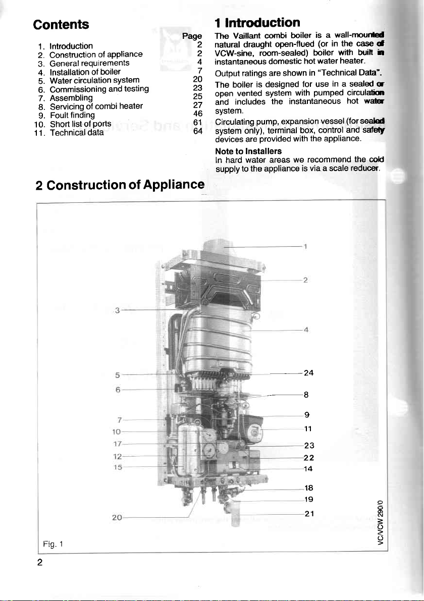
2 Construction
of aPPliance
reouirements
boiler
of
circulation
combi
of
finding
ports
list of
data
system
and
heater
testing
of
P4e The
2 natural draught
2
4
^l
;\
;;
,;
46
61
64 system
ApPliance
1 lntrcduction
Vaillant csnbi
VCW-sine,
instantaneous
Output
The
open
ahd
sYSIem.
Circulating
devices
Note to
ln hard
supply
room-sealed)
ratings are shown
is designed
boiler
vented
includes
pump,
only),
provided
are
Installers
water areas
to the appliance
boiler
open-flued
domestic
system
the instantaneous
expansion
terminal
wall-rnqrrH
is a
(or
in the case d
with buifr
boiler
hot water
in
for use
with
box,
with
we recommend
via a
is
heater,
"Technical
in
a sealed c
pumped
(forseald
vessel
control and
the appliance.
scale
Dda-.
circuldin
w&
hot
sdetf
the d
reducer.
it
2
trin I
-24
9
11
23
22
14
18
19
21
o
N
3
o
Page 3
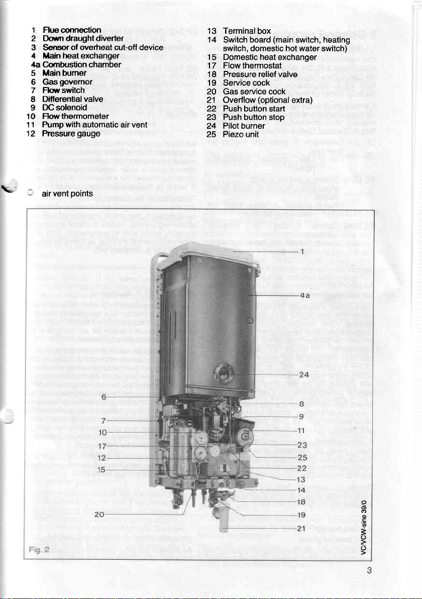
l Fkrcorinection
2 Down draught diverter
3 Sensorof
4 Mainheatexchanger
4a
Combustion
Main hrmer
5
6 Gasgovernor
7 Flowswitch
Differential valve
8
DC
9
10 Fbwthermometer
11 Pump
12 Pressuregauge
\a-
l
vent
air
overheat cut-off
solenoid
with
automatic air vent
points
chamber
device
Terminal
13
14
Switch
switch, domestic hot water switch)
Domestic heat
15
Flowthermostat
17
'18
Pressure relief valve
19
Service cock
20
Gas service cock
Overflow
21
Push
22
Push button stop
23
Pilot burner
24
Piezo unit
25
box
(main
board
exchanger
(optional
button start
switch,
extra)
heating
o
o
'6
=
o
Page 4
General
3
Related
3.1
installation
The
accordance
the Gas
tions,
the
It
vant
relevani
British
CP 331
BS 5376
BS
3.2
3.2.1
The
oermit
ierminal.
adequate
around
electrical
with
boiler
Where
be
give
A
Safety
l.E.E.
Water Undertaking.
local
be
should
requirements
recommendations
Standard
Installation
lown
Part
Selection
of
gases).
Part
Central
5449
oremrses.
Part
Location
Vcwqjle
location
the
The
space
the
installed
attention
l.E.E.
in an
boiler
specifically
board
that
Details
compartment
instdllations
in any
is cjrawn
Regulations
provisions
respect
in a room
installation
the
unusual
necessary
detailed
compartment
must
iompartment
or
modified
it is
of
requirements
documents
the combi
of
with the
Begulations.),
Regulations,
in accordance
the
of
Codes
of
gas,
Low
3:
pipes.
and
gas
space
2 Boilers
exceeding
heating
1 Forced
syslems.
(8.F. APP|iance)
dhosen
provisions
location
for servicing
The combi
heater.
room,
to
of
the
to
containing
location,
BS
and
guidance on
used
be designed
purpose. An existing
this
for
the
for
essential
design
given
are
boiler
relevant
for
installation
including
requirements
and
also
local authority
of
Practice:
of
pipes
Pressure
installation
heating
rated
of
60
circulation
the combi
satisfactory
of a
must also
and air
although
the requirements
in Scotland,
and,
the building
bath or
a
combi boilerwill
of the
special
5546 and
this aspect.
to enclose
and constructed
may be
purpose.
features
in BS 5376
must be
regula-
building
the byelaws
with any
the
and
(1
. and
kW.
for domestic
boiler
of the combi
procedures
used
of
airing
rele-
the
and
following
meters
installation
2. family
not
inPut
hot water
must
boiler
flue
provide
circulation
may be
particular
of
regulations,
shower.
may
BS 5376
the combi
cup-
provided
cupboardi
cupboard
: 2.
cP
in
of
BS 5440
ot
BS 5446:
for
We
connection
sealed
ditional
obtaining
3
.)
It is
by competent
above
correctly
your
ihat the
3.2.2
The
permit
bdequate
provide
circulation
The combi
the
containing
the
recommended
be
the combi
special
be
5'326
this
: 2
combi
specifically
bbard
that
Details
compartment
installations
342 Centralized
Part
Part 2
hot water
1 Individual
Buildings
dwellings.
Flues
appliances
60
ding
Part 1
kW
Flues
of
(1.
rated
and
air suPPlY
and
Part 2 Air suPPlY.
1979
Installation
supplies
like to drawyourattention
primary
and
8
Safety
Gas
the law
regulations.
own
VCW
location
fitted
:2 and
aspect.
boiler
or iompartment
it is modified
the
for
circuit
water undertaking
upon a
consentfora
(1)
from
Regulation,
that all
persons
lead
bould
interest
law is complied
(O.F.
chosen
provision
the
air supply.
adequate
around
boiler
bath or
a
that
in a bedroom.
boiler
procedures
BS 5546
A compartment
must
this
for
of essential
design
are
of
for domestic
filling or
from
relaxation
the Secretary
gas
appliances
in accordance
Failure
prosecution. This
to
that of safety
and
with.
APPliance)
for the combi
of a satisfactory
The location
space
the appliance.
not be installed
must
shower.
the combi
Where
in
be
will
may be
give
be designed
purpose. An existing op-
may be used
purpose.
for the
features
including
given
in BS
suPPlY
dwellings,
than
other
for
input not
familY
2.
gas
hot
PurPoses
tothefactthd
replenishing ol
a supply
1972:
to
for servicing
an
detailed
pipe
seeking aa
otits
of State.
are
install appliar a
to erisG
boiler
must fu
In addition,
should
boiler
installationd
the
unusual
necessary
guidanceot
to enclosete
used
and construec
of cupboard
cupboad
airing
: 2.
5376
is
can
Byeh
ins{d
with t:
b L
nrrsl
flue ad
ard *
rqq
in a
it
rd
posilb\
and BS
provided
a
,
b
supply
Gas
3.3
3.3.1 Service
The
installation
planning
gas
local
4
pipes
region should
in order
stage
be consulted
at the
to establish
availability
the
An existing
prior
out
consultation
an adequate
of
service
pipe
with the
must
gas.
of
supply
not be used
gas
local
regiorl
wit>
Page 5
Meters
3.3.2
gas
A
meter is
connected
gas
local
the
contractor.
An
existing
that it is capable of
2.95 ms/h
(or
3.38
2.47 melh
installed.
Flue
3.4
Detailed
in BS
5440
give general
to
VCW-sine
3.4.1
\=i=
The
boiler
terminal is
Termination should be on a clear expanse
wall;
the terminal being
600 mm
projecilon.
Do not install the terminal:
Within
a)
from the
vent,
b) Within
ground
Within
c)
the terminal.
lmmediately
d)
Where the lowest
than 2 m
balcony, flat roof
access,
guard
of durable
guard
is available as an optional extra with
combi boiler. The air inleVproducts
and the terminal of the boiler must not
than 50
Detailed recommendations
combustible
VCW
3.4.2
Detailed recommendations for fluing
in BS 5440 : 1 . The following notes
give general guidance.
to
The
cross sectional
combi boiler must be not less
the flue outlet of the appliance. An
supplied to allow the fitting of 125 mm
pipe
or 125 mm light
When fitting flue
connector
disconnection of
16).
fig.
region
meter should be checked to
(106
(122
mslh
(89
CFH)
system
recommendations for fluing
: 1. Thefollowing notes
guidance.
(B.F.
must be installed so that the flue
exposed
(2
ft.) awayfrom acorner, a recessora
mm
300
bottom of an openable window,
or any other
mm
300
level.
600 mm
beneath eaves or a balcony.
(6,6
ft.) above the level
mm
material
(O.F.
must
or
material.
(2
in.)
Appliance)
the terminal must
to the
a local
or
passing
CFH) before the VCW
CFH) before
the VCW-sine 18)
before
Appliance)
to the external
preferably
(1
ft.) measured
ventilation
(1
ft.)
above adjacent
(2
ft.) of any
part
the termlnal
of
place
to which
protected
by
A terminal
to combustible material.
on
given
are
area of
asbestos cement
pipes
fitted
be
the flue
in BS 5440 : 1.
the flue
than the
a split
to ensure
pipe (see page
pipe
service
gas
region
ensure
an additional
the VCW
not less
opening.
surface facing
of any
Drotection
are
intended
are
air.
vertically
is less
ground,
people
protective
outlet duct
be closer
are
intended
are
fitted to
area of
adapter is
steel flue
flue
socket
25
given
than
have
by
the
given
the
pipe.
easy
13
lnstallation
3.3.3
by
Installation
with CP
must
a smaller
20
connection.
or
The
is
soundness
Flue
from
a) Asbestos cement,
b) Aluminium
c) Cast-iron
lf double-walled flue
of
a type acceptable to British
lf
that is
acid-resistant
with
acceptable if the
540
materials in
air
connection
chimney
or lined with a non-porous
material it should be lined with
flexible flue liner or any
type acceptable to British
meter
in the technical
mustbe kepttoaminimum. lf
to be connected
a
draught diveder a flue
constructed from
above should
draught diverter and
Before
inserting a liner into,
of
previously
swept clean of any soot
register
fitted
connecting the
liner into, the flue.
The
the relevant
5440:1, table 4.
A terminal
found
fitted
The
600
or any other ventilation
331
Pipework
be of a adequate
complete installation
pipes
one of the following materials:
lined.
a chimney
composed of or lined with a nonporous
salt-glazed earthenware
: 1 .) A flue
is to
of the liner must
connecting the combi
plate,
in the flue, it must
flue should terminate
satisfactory by British
the flue
at
point
(2
mm
pipes
pipes
should
:3.
from the meter
than
size
as described in the
fittings
and
or stainless steel,
acid-resistant
is
used it
material.
pipes
pipe
a) to c) above
to lined
be used which is not composed
data and the number
directly to the combi boiler
one of the materials in
form
the connection
used, the flue must
restrictor
combi boiler to, or inserting
recommendations
of a type
outlet.
of termination must
ft.)
of an openable window,
fitted
be
in accordance
to the
size. Do not
the
should be constructed
pipe
is
preferably
comply with BS 65 and
constructed from
should
chimneys. Where
other
Gas.
not be less than
flue
liner.
a flue that has been
and
plate,
that has
opening.
combi
use
combi boiler
must
be tested
above
vitreous
used it should be of
Gas.
should be one
(Chimneys
pipes
one of the
form the initial
acid-resistant
a stainless steel
liner
that is of a
The internal
thefluelinerisnot
pipe
which is
between
boiler
be thoroughly
loose material. lf
damper etc.
be removed before
in
accordance with
given
been tested and
Gas
should be
not be within
boiler
pipes
gas
Code.
enamel
lined
dia-
shown
joints
of
to
a)
the
to,
in BS
air vent
of
for
are
a
of
c)
or
a
is
a
c
Page 6

Air supPlY
3.5
Detailed
given in
intended
3.5.1
The
located
vent
an adiacent
itself
i-n" same
3.5.2
Where
cuoboard
are
case
combustion
compaftment
recommendations
BS 5440
give general
to
Room
or
room
must
be
must
'have
sizd
Cupboard
combi
the
or
required
open
6f
of
Pos.
vents
air
High
Level
LOW
Level
The
2.
:
guidance.
internal
or
space
have
either
room
permanent
a
compartment,
(for
and
at
space
in which
permanent air
a
to the
direct
internal
or
to
direct
compartment
or
is to be
boiler
cooling
appliances
flued
flue dilution)
high and
vcw20/1
vcw25/1
VCW-sine
vcw20/1
vcw25i1
VCW-sine
supply
for air
following
air
the
permanent air
purposes and
low level'
air supply
the
outside
space
vent of
outside
installed
in the
notes
boiler
vent'
which
air supply
also
cupboard
These air
This
or
air
must
least
at
The
air.
vents
in
Airfrom
internal
cmz
280
320
235
560
640
,235
minimum
vent(s)
are
maximum
are
is
to
The balanced
does
have a oermanent
vents
internal
or
in a
the
for
or
minimum
The
vents
air
compartment
are ielated
the unit.
room
space
,
{42)
(50)
(36,5)
(84)
(1
(36,5)
effective
is specified
rated
Appliance
vcw20/1
vcw25/1
require
not
either
must
space
etfective
required
are specified
to the
vent areas
Air
or
(inr)
00)
area
below
input
heat
combi
flued
room
the
vent.
air
communicate
direct
or be
areas
in the
niaximum
Airdirectfrom
cm2
140
160
120
280
320
120
permanent
of
is
and
the unit.
of
cmz
108
130
boiler,
internal
or
to outside
the
of
below
rated
outside
I
to
related
in.2
16
20
VCW-sine,
space
the
with
air.
permanent
cupboard
(Tab. 1)
input
heat
(inr)
(21)
(25)
(18,5)
(42)
(50)
(18,5)
air
the
to
room
or
and
of
Tab.1
Both
Note:
the
both
be
air.
Effect
3.5.3
is anv
lf there
oremises
iir
ipittag"
3.6
Detailed
circulation
5449
heatinq
notes
not forming
should
and
6
there
area
inlet
of
Water
(Jor
:1
svstems)
ire
belnsulated
possible
air
same
on
an
of
tvpe
i6
from
products from
the
circulation
recommendations
system
small
particular importance.
of
pbrt
freezing,
room
the
extract
of
possibility
the
are
bore
and
the
ot
internal
or
wall
same
fan
extract
outside
system
given in BS
and
342-
CP
useful
help
to
particularly
communicate
must
vents
or
space
the outside
to
fitted
fan
if adequate
that
provided
is not
open
the
the
for
5376
bore
micro
prevent heat
following
the
Pipework
heating
where
surface
with
must
the
in
flued
water
BS
:2'
central
loss
pipes
cupboard
Where
communichte
room
the
permanent air
combi
is
fan
occur
must
taken.
are
underfloor
Draininq
oosition-s
svstem
water
1/2 in.
2879.
BS
internal
or
boilers
in operation.
a spiilage
be carried
through
run
sPaces.
taps
which
including
system.
nominal
or
the
with
vent(s)
could
flue
test
out
roof
must
permit
the combi
Dlaining
size
compartment
or
room
must
space
specified
as
when
occur
such
Where
detailed
as
and
be
and
necessary
any
spaces
located
draining
the
heater
should
taps
in accordance
be
vents
air
internal
and
space
have
itself
in 3.5.1.
extract
the
installations
BS 5440.:
in
actlon
ventilated
in accessible
whole
the
of
the
and
least
at
be
with
a
1
hot
Page 7
Electrical supply
3.7
Wiring
The combi boiler
external
installed in accordance
be
Regulations
apply.
4 lnstallation
4.1 General
The combi
flat area of
vertical
measure as shown
This
area does
installation and servicing.
fitted on a
be
should
material.
\-
In addition. a minimum clearance of
to the combi boiler
and any
local regulations which
is
supplied
of
is to be wall-mounted and a
boiler
wall is required which must
on template-
not include
wall
of combustible
protected
by a sheet of fireproof
with the l.E.E.
for 22O/24O V,
boiler
clearance
lf the
appliance
material,
must
the wall
400
50 Hz. Fuse rating is
The
combi boiler has to
the mains
terminal
For wiring
(16
appliance to enable the
servrceo.
Service clearance of 150 mm
side
For the
for
and
is
the flue. The
2
cartons, one containing
the
carton containing the terminal/duct
delivered with the balanced flued appliance.
mm
electricity supply
box.
instructions
in.) must
is reouired.
open
25/1
an additional clearance is required for
installation
o
o
c
o6
>o-
FO.
(U
3 A.
be connected
paragraph
see
be available at the front of the
flue
combi boiler is supplied in
accessories. An additional
combi boiler to be
type appliances VCW 2011
the
vcw20/1 vcw25/1
using the internal
direct to
4.7.
(6
inches)
either
boiler, the other
assembly
is
F
,l
E-
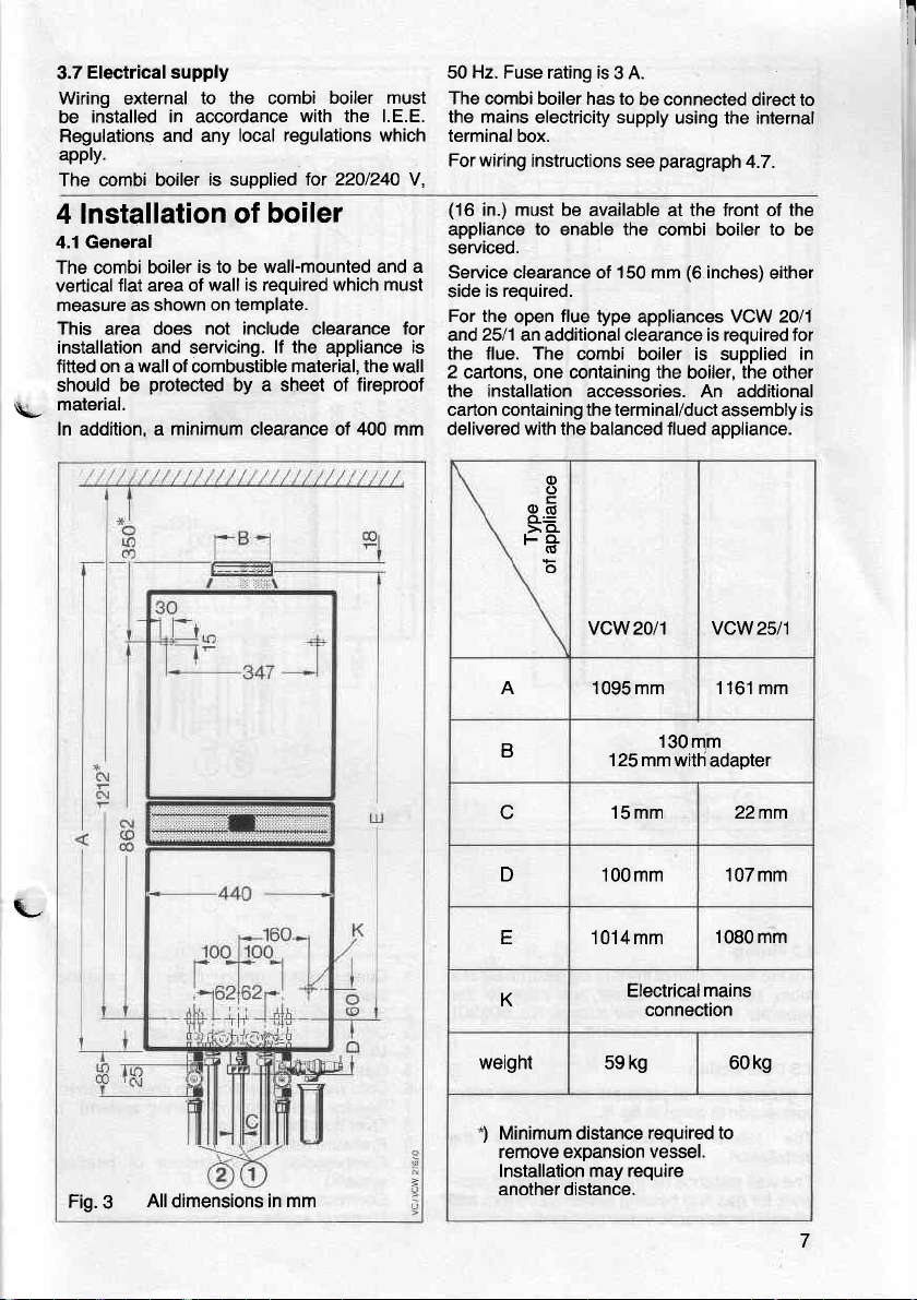
Fig.3
All
dimensions
in mm
A 1095 mm 1161 mm
B
D
r
1014mm 1080 mm
K
weight 59 kg 60 kg
Minimum distance
)
remove expansion vessel.
130mm
125
mm with adaoter
15mm 22mm
'l00mm
Electrical
connection
107mm
mains
required to
Installation may require
another distance.
7
Page 8
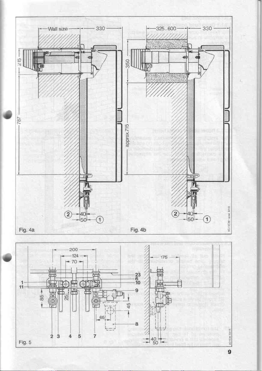
Fluing
4.2
installation
the
For
room
.!-o"t"i"
iniluded
-in.t"llation
sealed
with
4.3 Connection
A oeneral
coinection
The
view
is
following
installation.
The
woit<
40
gas
toi
for domestic
mm
and
distance
wall
8
of
combi
every
pipework
of
given
procedure
(to
hbating
flue
the
boiler,
nstructions
i
flue set.
5.
fig.
in
finished
the
system
water
PiPework'
(wall
set
reter-to
we
gas
for
describes
wall)
is.50
case)
No'
and
ot a
rne
806901
water
the
pipe-
of
mm and
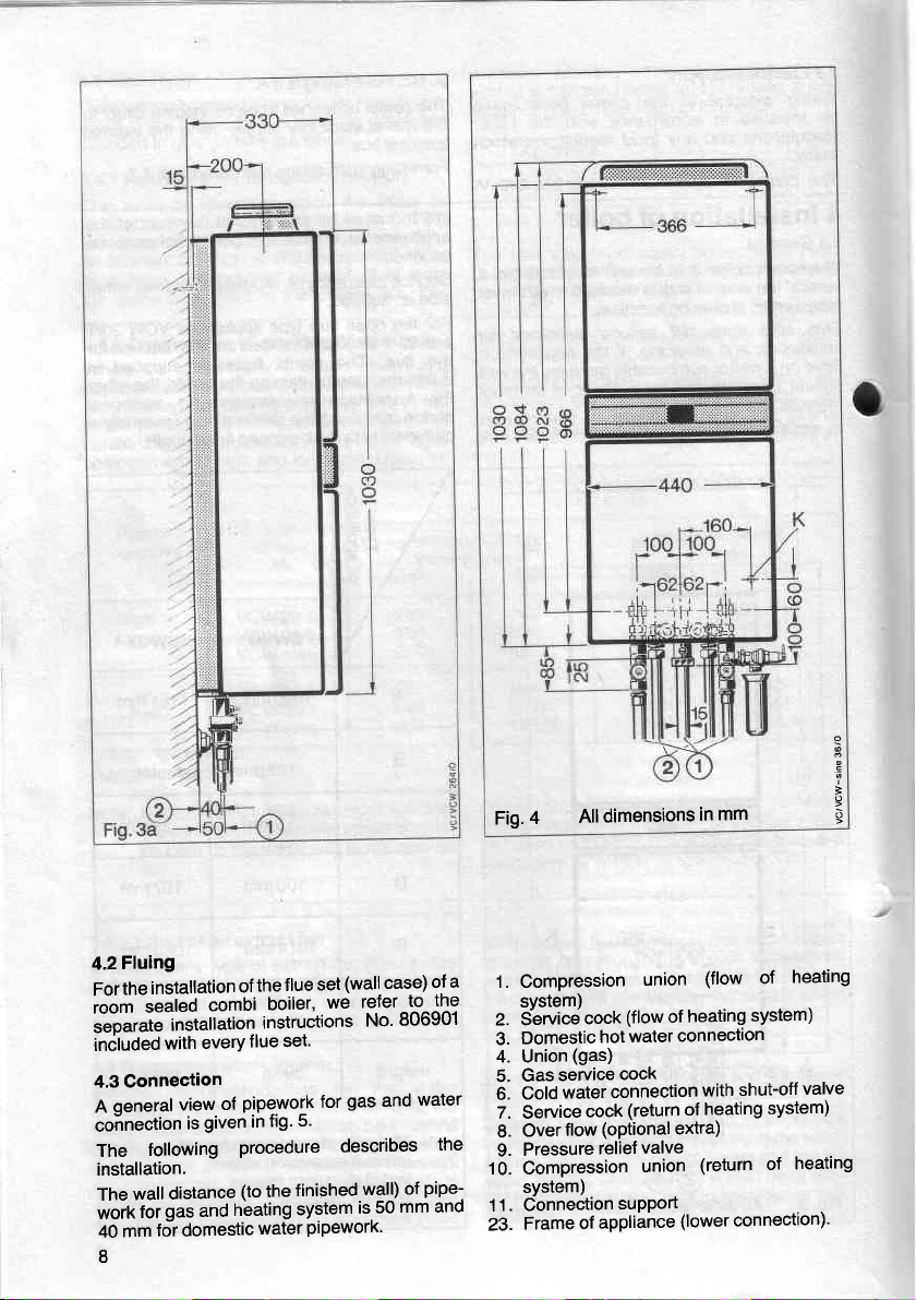
Fig.4
All dimensions
1. Compression
svstem)
z. S-ervice
3.
4. Union
5.
6.
7. Service
8.
9.
cock
Domestic
(gas)
service
Gas
water
Cold
cock
flow
Over
Pressure
hot
cock
connection
(optional
relief
10. Compression
system)
Connection
11.
Frame
23.
support
of appliance
union
(flow
of
water
(return
valve
union
mm
in
(flow
system)
heating
connection
shut-off
with
heating
of
extra)
(return of
(lower
connection)'
heating
of
valve
system)
heating
!
;
t
Page 9
,,4
I
Page 10
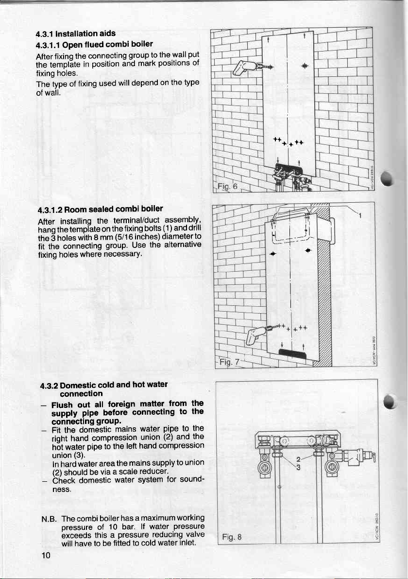
lnstallation
4.3.1
4.3.1.1
fixing
After
template
the
holes.
fixing
type
The
wall.
of
4.3.1.2
After
the
hano
holes
the 5
fit the
holes
fixing
flued
Open
connecting
the
position
in
used
of fixing
sealed
Room
installinq
connecting
the
tempi-ate
8
with
where
aids
boiler
combi
group to
ancl
will depend
combi
terminal/duct
fixing
the
on
(5/16
group.
inches)
Use
mm
necessary.
thewall
posltlons
mark
on the
boiler
assembly,
(1
bolts
and
)
diameterto
the alternative
put
oI
type
drill
I
I
**!**o
rl
I ll
fl | )l
+1-
I
Domestic
4.3.2
connection
-
Flush
supply
connecting
-
the
Fit
riqht
water
h5t
union
ln hard
(2)
should
-
bhect
ness.
Thecombi
N.B.
oressure
bxceeds
will
10
cold
all
out
pipe
grouP.
domestic
compression
hand
pipe
(3).
area
water
be
domestic
of
this a
have to
watel
hot
and
loreign
before
to
via
boilerhas
10 bar.
be
matter
connecting
water
mains
union
left hand
the
mains supply
the
reducer'
a scale
system
water
amaximumworking
lf water
pressure reducing
to cold
fitted
the
from
the
to
pipe
(2)
compression
water
the
to
the
and
to union
for sound-
pressure
valve
inlet.
Page 11
I
I
I
I
I
t
{33
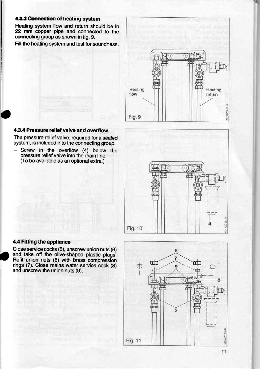
Gonnection of heating
Fledirtg
2. rrtn
cqrtecting
Ftl
syslem flow
copper
group
lhe heating system
return
and
pipe
and connected
as
shown in fig.
and test for
system
should
9.
soundness.
be in
to
the
4.3.4 Pressure relief valve
pressure
The
system, is included into
-
Screw
pressure
(To
4.4 Fitting
Close service cocks
take
and
Refit union nuts
(7).
rings
I
and unscrew
relief
in
relief valve into
be availableas
the appliance
off the
Close mains water
the union nutF
valve, required
the
the
overflow
an optional
(5),
unscrew
olive-shaped
(6)
with
and overflow
for
a sealed
connecting
(4)
the
brass'compr6ssi-on
service
(9).
group.
below
drain line.
extra.)
union nuts
plastic
plugS.
cock
the
(6)
(8)
*-A-6
Page 12

flued
Open
4.4.1
from
pait
boiler
ing
unions
bolts(1)
the
8.1'1.),
in
aids
tubes
Unpack
oarieis las
inO
the ionneciions.
connection
oiession
it on to
aPPliance
carton
lint
well
as
the
Insert
downwards
service
the
of
fasten
and
remove
and
arrestor
(as in 8'2'2)
plastic caps.from
as
appliance
into
cocks
screws
the
and
wltn
(10)'
side
tne
comhang
compression
Fasten
ig),
4.4.2
Unoack
Janels
blastic
buct
the t;le6copic
assemblY.
Insert
downward
service
bolts
compression
is,
(11,fig.13).
using
Balanced
(as
baps
(20)
the
cocks
the
of
iig.
thb
boiler
in 8.1.1
irtitn
appliance
iirio
13)
unions
attached
lued
f
carton
from
.) and
the
from
2 sheet
tne
(16)
duct
with
compression
the
hang
and
case
wall
unions
using
(6,
(6)
and
(1
washers
aPPliance
packing
connections.
(1),
fig.
the
1)'
remove
and
aids
metal screws
terminal/duct
the
of
connection
the
unions
to the
on
it
14.
fig.
13) and
attached
union
wellas
as
Fit the
(22) to
threaded
Fasten
union
washers
nuts
side
flue
tubes
the
of
nuts,
nuts
Fig.
14
1 Fixing
Telescopic
16
22 Sheet
1 9,
Flue
20
Flue
2'l
bolts
duct
bend
20
duct
metal
21
screw
12
Page 13
45 Gcconnection
Frt the
Cleil
s.Dpty
service
Connect
and tighten.
a
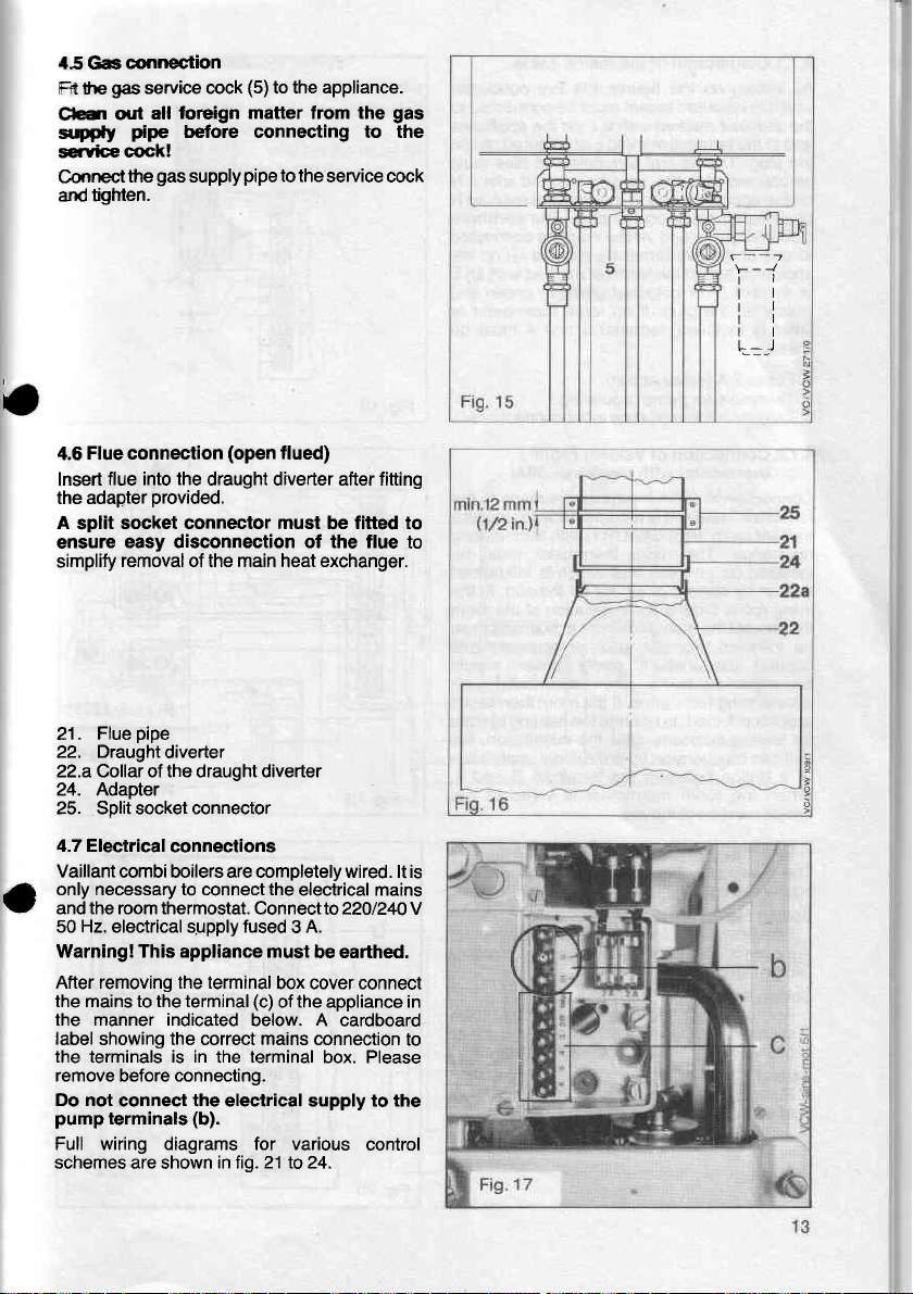
Flue connection
4.6
Insert flue
the adapter
A
split
ensure
simplify
gas
service cock
foreign matter from the
all
out
pipe
cock!
gas
the
into the
provided.
socket connector must be fitted
easy disconnection of the flue
removal of the main heat exchanger.
(5)
to the appliance.
before connecting to the
pipe
(open
to the
flued)
service cock
supply
draught diverter after fitting
gas
to
F--i
tl
tl
tl
ri
to
22.
22.aCollar otthe draught diverter
24. Adapter
25. Splitsocketconnector
4.7 Electrical
Vaillant
only necessary to connect the
a
and the room thermostat.
50 Hz. electrical sgpply fused 3 A.
Warning!This appliance must
After removing the terminal
the mains to the terminal
the manner indicated
label
showing the correct mains connection
the terminals is in
remove before connecting.
Do not
pump
Full wiring diagrams for various
schemes are shown
diverter
connections
combi boilers are completelywired. lt is
the
connect the electrical supply to the
terminals
(b).
intig.21 Io 24.
pipe
. Flue
21
Draught
electrical mains
Connectto220/240v
be earthed.
box cover connect
(c)
of the appliance in
below. A cardboard
terminal
box. Please
to
control
Page 14
Connection
4.7.1
shown
As
is coloured
*nicn
terminal
the
inO
the Dluq.
6e
on tne
oi
coloured
i" rn"
"opiiin""
oi svmbol O
vellow
iimer
linked.
a.
b.
i-
4.7.2
--
Connection
terminiri
Vaillant
resistance.
inJiiiteo
neiiner
livinq
therftostat
be
iotfurt
be
icceleiating
is
ior
,nit "an
oi
Wfren
bridge
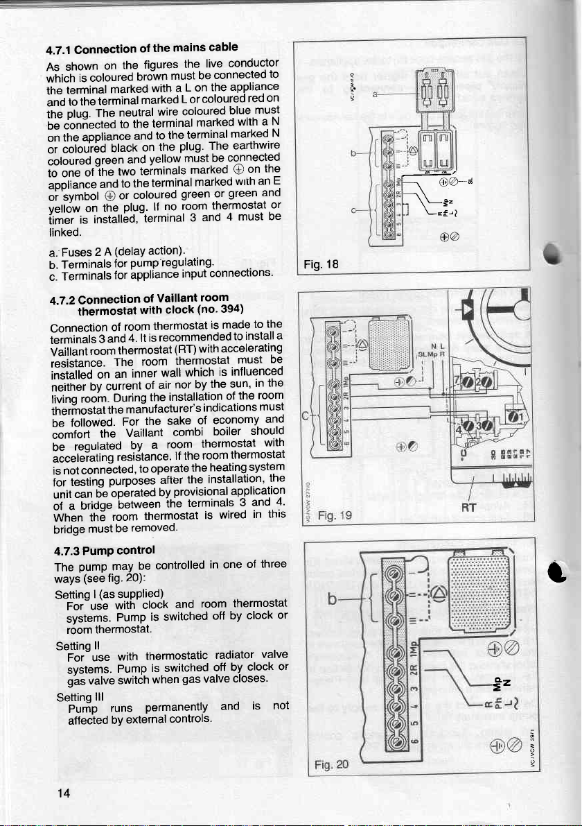
4.7.3
The
ways
Settinq
Setting
tetminal
tne
to
The
ioni"ct"O
aoptiance
coioureO
qreen
otine
and
on
installbd,-terminal
is
2
Fuses
Terminals
Terminals
Connection
thermostat
g
room
on
Ov
rooin.
followed.
the
requlated
not connected,
i"iting
bi
OriOge
a
tfrE
must
PumP
pump
(see
(as
I
For-use
systems.
thermostat.
room
ll
For"use
svstems.
valve
o'as
ttl
seltting
Purip
affected
the
of
figures
the
on
brown
marked
the
A
anO
current
the
purposes'after
fig.
runs
with
marked
wire
neutral
terminal
the
to
black
two
to the
or
plug.
(delay
for
for hppliance
room
of
thermostat
The
an
During
For
Vaillant
resiitance.
op6rated
between
room
be
control
may
suPPlied)
with
Pump
with
Pump
switih
bY
the
to
and
the
on
yellow
and
teiminals
terminal
coloured
no
lf
action).
pump regulating'
Vaillant
of
clock
with
thermostat
recommended
is
4. lt
room
wall
inner
air
of
the
manufacturer's
sake
the
room
a
by
to operate
by
ihe
thermostat
removed.
controlled
be
20):
clock
is switched
thermostatic
is switched
when
Permanently
external
cable
mains
conductor
live
the
connected
be
must
the
L on
a
L or coloured
coloured
marked
terminal
plug' The
be
must
marked
marked
green or
thermostat
room
input
(RT) with
thermostat
which
nor by
installation
combi
lf the
provisional application
and
gas
controls.
4 must
and
3
connections'
room
(no'
394)
is made
accelerating
is
the sun,
of
indications
economy
of
boiler
thermostat
room
heating
the
installation,
the
terminals
wired
is
in one
room
off by
radiator
off
valve
and
to
appliance
on
red
must
blue
a
with
marked
earthwire
connected
the
on
O
an
wrth
green ano
or
be
the
to
install
to
De
must
influenced
the
in
room
the
must
and
should
with
thermostat
system
the
and
3
this
in
three
of
thermostat
clock
valve
clock
by
closes'
is
N
N
E
a
4'
not
or
or
Fig.18
1
..'\L*=
LEf,-l
-j
@@_a
@a
t
Sz
14
i
Page 15
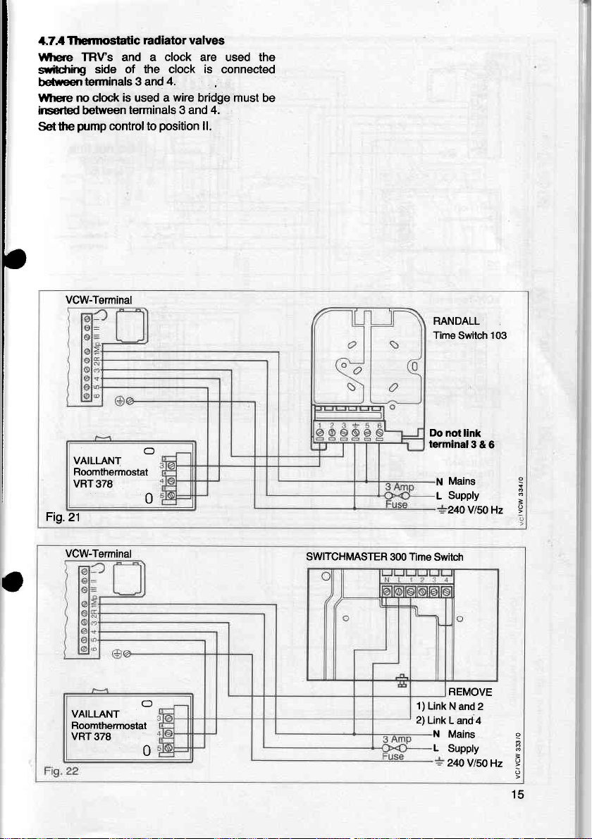
Thcrmostatic
1,7,
TRVs and a
l$rere
ilibfrirg
betreen
lYhere
side of the clock is connected
teminals 3 and
no clock is used a
inserted between
pump
Setthe
VCW-Terminal
Fig.21
control to
VAILLANT
Roomthermostat
VBT378
radiator valves
clock
are used the
4.
wire
bridge
lerminals 3 and 4.
position
ll.
0
must be
RANDALL
TimeSwitch 103
Do
not link
terminal3
N
L
& 6
Mains
Supply
24OV/5OHz
I
a
VCW-Terminal
VAILLANT
Roomthermostat
VRT378
SWITCHMASTER
O
0
300
Time
1)
2)
Switch
REMOVE
Link N
and 2
Link
L and:4
N
Mains
L
Supply
24OVlsOHz
3
15
Page 16
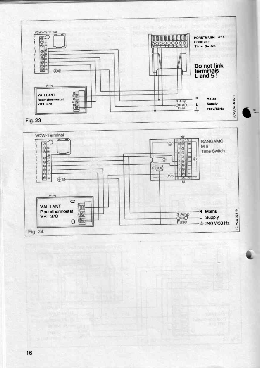
Fig.23
LLANT
VAI
Foomlhetmostat
3 78
vRT
HORSTMANN
COFONET
Time Switch
link
not
Do
terminals
Land5!
N
t.in"
SuPPIY
L
2r0v/50H2
J
125
3
o
l':-'
VAILLANT
Roomthermostat
VRT 378
16
O
N Mains
SUPPIY
0
L
24ovl5oHz
+
B
Page 17
l
I
I
I
b
i
i
E
-9-
6=O
E;E
9p5
;
a
E
o
a
cl
c
3
p
o
c
o
o
a?
o
o
"9=i
E$s
a
lt^
ol
988-
x*'t
:oo
o(g
F
.o
(,
CD
lo
(o
I
3
o
'
o
=
;
",
1
EY
r()
AI
.st,
tt
E
o
o
o
c
'=
Page 18
15
14
13
'12
11
10
9
I
7
6
5
70
71
73
54
5:l
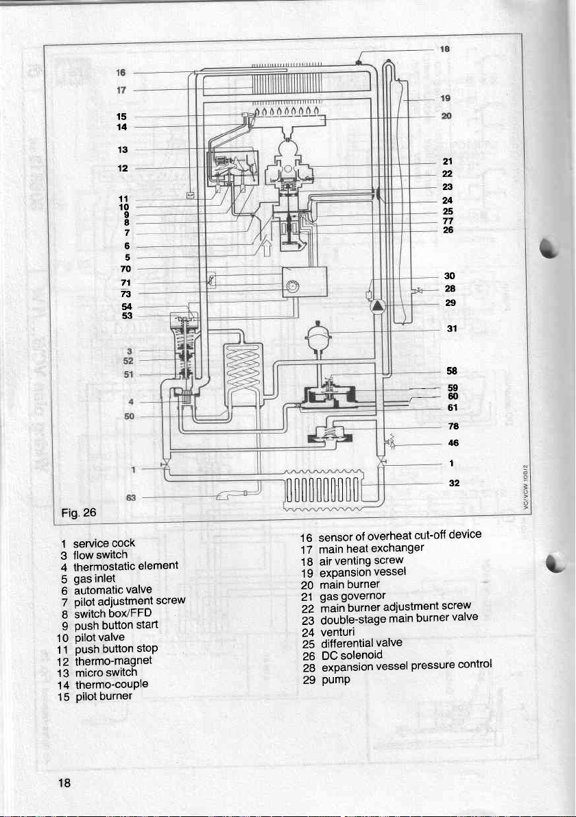
Fig.26
flow
cock
switch
1 service
3
4 thermostatic
gas inlet
5
6 automatic
pilot
7
switch
I
9 oush
pilot
10
push button
1 1
thermo-magnet
12
micro
13
thermo-couple
14
pilot
15
valve
adiustment
box/FFD
button
valve
switch
burner
element
screw
start
stop
0t[|il[[|ll
overheat
1 6 sensor
17 main
18
19
20
21
22 main
i3
24
25
26
i8
29
of
excnanger
heat
screw
venting
air
expansionvesset
burner
main
governor
gas
burner
double-stage
venturi
differential
DC
expansion
pump
solenoid
valve
vessel
/-ffi
cut-off
..
adjustment
burner
main
pressure
21
n
23
24
25
77
26
30
2A
n
31
58
61
7A
46
1
32
device
screw
valve
control
18
Page 19
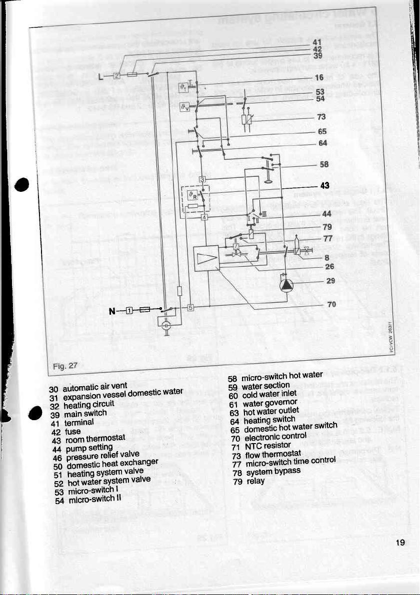
-'_-43
N--.a.-:.*.
water
sedlon
inlel
water
governor.
outlel
control
resistor
hot
.
switch
*"*"'
micro-switch
58
water
:li"#3[?t!l3ll
3?
32
39
i
i
41
X3
$i[#s$:rrtt:"'
53
54
circutr
heating
switch
main
terminal
tlo"o"*
rn"rto""'
micro-switcn
micro'switcn
o"'"""'ic
t.
ll
water
59
cold
60
water
61
water
hot
63
!3il'J3-:Y':ilvarcr
3e
electronic
70
NTC
71
"1.1H,$3#3f;'ftL
1?
systembypass
78
relaY
79
19
Page 20

Water
5
General
5.1
The combi
minibore
It is
2871
The use
avoided
air
and
recommended
:1for
wherever
collecting
circulating
is
boiler
water
of
suitable
microbore
to use
carrying
horizontal
possible
the system.
in
systems.
pipe
system
use on
for
tubing
copper
PiPework.
runs
in order
lf horizontal
most
to
should
prevent
to
unavoidable
are
towards
For
BS
be
runs
mide
be
-
SPECIFICATIONS
CENTRAL
to
and
point.
a vent
qeneral
MATERIAL
BS 5376:2
quidance
ihe
to
HEATING
the
pipes
British
AND
AND
and
should
reference
Gas
INSTALLATION
FOR
HOTWATER
BS 5449
rise upwards
should
publication
DOMESTIC
-,
:1.
B
Single
5.1.1
The
circuit.
heat
can
fittinos
PiPe
emitters
heat
necessary
The
(radiator) must be
emitter
done
be
the return
in
The-radiator
temperature
of
basis
circuit.
Two-pipe
5.1.2
radiators
The
temperature
radiator.
central
Typical
following
the
to 5.5
5.2
NOTE:
and sealed
primary
The
N.B.
convenient
any
sYstem
installed
are
water
for instance
connection
shall
sizes
distribution
system
installed
are
therefore
heating
figures.
is the same
installation
are applicable
systems.
point
filling
point
on a closed
quantity
for every
ensured.
by using
of
be calculated
suction
the radiators.
on
around
parallel
may
the circuit.
on
the
and
for every
are shown
to both open
placed
be
This
the
the
Fig.28
flow
in
Filling Point
at
20
Fig.29
Page 21

S2Gontols
Vdilt
cofiti bcilers
oleebcLft:d mains.
conhds
W$Gn
h figures 21
sfwn
lrolating valves
53
The
+dianoe
(service
dws
4-3_3.
5.'tGirculating
The
cirolating
boiler. The remaining
betaken from
SssYstem by-pass
A
system
bdler.
(24OV)
shall
cocks)
pump
pump
the
diagram.
by-pass is
to 24.
ready
are
may
installed
be
as described
is included
conveying
included
for
connecting
be
connected
with isolatinq
into
the
capacity
into
the
as
unde-r
combi
can
combi
5.6 Open
lf it is required
systems
modification
recommend
isofation
the
British
a:
should
Min static head:
Max
see BS
2
3 expansion
7
vented
to
possible
it is
to
to fit
pressure
relief
(no.
valve
Standards
otl.gr requirements
be
strictly
0.15
static head:2.0
5449 clause 24.1
expansion
overflow
pipe
cistern
pipe
system
use the
combi
to
the
combi
the
expansion
7,tig.
valve is
and
Codes
involved
observed.
(5'water)
bar
(67'water)
bar
heater
in
heater.
(2)
normallv
The
relevani
as
also
ooen
W6
at the
well
3.1)
do so without'anv
pipe
12)
where
fitted.
of Practice
(see
800
176
1000
Fig.31
220
1200
264
14c,0
308 352 cPH
1600
L/h
21
Page 22

systems
Sealed
5.7
Sealed
exDansion
ouitiW
Jsed
systems
cisterns,
raOiator
in order
to
topping-uP.
Pressure
5.7.1
is required
This
connected'as
5.7.2
is
This
pressure
shown
Pressure
factory
the
in
do
open
valve's
prevent
lelief
all
on
gauge
to
fitted
Primary
require
not
vents
fittings
and
excessive
valve
sealed
4'3.4'
in
boiler
the
circuit.
leed
only
etc'
should
detrlmenlal
systems
shows
and
and
gooo
be
and
the
is
3
Expansion
5.7.3
expansion
litres
1 5
A
ihe combi
iuit".
260
lf the
vessel
itor-instance
iioen
cin Oe
ieturn
pressure relief
5.7.4
The
seoar6te
on'
Authority
connection
connection
b6iler
with
(57.2
litres
nominal
is not
Jvstems)
instatt6d
service
Filling
svstem
lilling
neati-nb
the
Regulation
to-the
must
completed.
Reqirlation
corinection,
break
witt
domestic
ln
waier
shown
Methods
appendix
must
tank
be
not
side.
principle,
mat<e-up
some
that
filling
of
of
A
vessel
vessel
suitable
maximum
a
galls')
lmP.
capacity
sufficient
in
of
case
additional
an
the
to
in connection
cock
valve.
make
and
be
should
point
fitted
circuit.
mains
be
Where
does
a sealed
used.
be
automatically
filled
sealed
faciliti6s,
make-up
sealed
BS 5376:2.
is incorporated
a sealed
of
for
for
the
water
built-in
heating
the
contents
expansion
modernization
expansion
connection
side
uP
water
with
filled
a convenientpoint
at
local
Where
allows,
removecl
local
not
system
systems
a
b,e
may
when
Water
allow
filler
heating
The
do
experience
but
may be
systems
not
necessary'
are
into
heating-
of
sys,tem.
old
of
ve-ssel
the
of
the
with
a
via
Water
temporary
The
used'
lllllng
ls
Authority
temporary
pump
with
system
the
from
require
has
given in
Fig.32
Pipework
5.7.5
All oioework
run'n'eatly
and
be securely
shall
concealed
be
supported,
possible'
where
shall
22
Page 23

6 Cornmissioning
testing
6, 1
El€ctrical
r-e,'rinary
+€sflcal
:r,mpetent
r
tne INSTRUCTIONS
IiIULTIMETER.
6.2 Gas installation
Tne
reter.
soundness
iecommendations
t
6.3 Water
The
whole
wtrn
Dotn
are
open.
With
the
be
fiiled
through
Loosen
-z
oy 1
for.water
until
the
PSI).
(The
system
from
a
or
La_lK.
5376
: 2,
Check
Trom
rne
oL.-t,z
otnerence.
gauge
emtner
whole
sealed
operation
oat
and
ts
installation
electrical
safety
person.
of the
should
be inspected
purged
and
circulation
oJ the
cotd
and
combi
boiler
and
air
the
the
turns.
pressure
by
system
locks
4
vent
black
Vent
soundness.
should
system
a
method
appendix
of
until
ts
atatned,
in
height
rhe point
connected_
sysiem
shall
Those
gas
installation,
of
Cp
system
system
hot
water.
fitted,
cteared.
points
cap
on the
all
heat
On
gauge
be filled
filler pump
of filling
A.)
safety
the
initial
taking
between
at
which
and
checks
be
carried
checks
FOR
BR|T|SH
and
in
accordance
331 :
3.
should
be flushed
Ensure
the
system
V6nt
shown
ln
automaiic
emitters
a
sealed
registers
with
given
valve.
Release
system
into
the
the
higtiest
to
out
are
outliired
includinq
testej
with
all valves
should
tnJOoifei
tiq.
iand'2.
air
and
check
svstem
t.s
iraiizr.S
water
either
with
a
break
in
water
pressure
account
pressur6
ensure
by
GAS
the
for
the
out
vent
fiti
BS
anv
heat
a
Fig.33
t
components
detection
6.4.2
Pull
matn
pressure
6.4
Lighting
The
first
lighting
quatttied
oy
a
verbat
instructions
operate
the
generally.
separately
6.4,1
Gas
Test
gas
for
fluid.
Main
off the plug
Durner
test
the
combi
of the
fitteronly.
combi
boiler,
Light
the
"lnstructions
in
the
soundness
soundness
using
burner
pressure
of the
pressure
point.
boiter
appliance
He
shall
to
the
user
controls
combi
boiler
for
around
sense
of
smell
NTC-resistor
at
the
shall
be
also give
on
how
and
systemi
as
described
use,,.
boiler
and
and
test
main
burnei
done
clear
to
qas
l6ak
the
23
Page 24

Nominal
6.4.2.1
pressure
The
intetbressure:20
burner
main
2011
vcw
2511
vcw
VCW-sine
The apoliance
.b'ti"5i
n"lJ""urv
g"d gouernor
"itne
pilot
adiustment
1
pilot gas
2
solenoid
DC
3
burner
+ main
gasgovenor
5
blocking
6
inLipti.irte
7
Flue
6.4.3
that
Check
JomOustion
carryinq
i
il6'
aooliances.)
lii,irl"-"iihrtish
LturitLn,
ii'tn"l"li
Flame
6.4.4
the
Check
donoiuoiler
"'"'ini
"tt
"iir,li
seconos.
heating
must
mbar
pressure
18
is
neating
to a[6r
filter
Pressure
Plate
test
there
from
spillage
a
r.
thppiicaote
Check
check
tvpe
lriv
tailure
operation
to
sit
regulated
influt.
thb
is
the
thatihere
inPut
follows:
as
be
(8.08
in'
(cold
and
mbar
9.0
mbar
9.0
mbar
10.6
at
Therefore
of
setting
installation'
during
screw
test
Point
(near rear
point
spillage
no
draught
down
as
test
only
appearance
is
outlined
as
also
of
extract
fan
device
flame
the
of
that
ensure
to
main
the
WG)
hot):
(3.61
(3.61
(4.26
factory
it
or
.input
plate)
products,of
of
diverter
detalleo
open{lued
to
llames
ol
adequate
under
fitted'
failure
device
the
within
burner
WG)
in.
WG)
in.
wG)
in.
to
is
output
In
air
3'5'3
devic.e
the
not
by
t:D
In
for
will
60
Flow
6.4.5
the
Check
Jontiofs
controls
6.5
Allow
woif<inq
iornon""...
off
iu.t".
idcis.
the
are
to appropriate
Water
the
temperatuie
rapidly
ind
should
Sealed
initial
Examine
for
thermostat
thermostat
flow
operating
soundness
system
water
ihe system
drained
again
sistems
design
system
water
soundness.
and
satisfactorily'
settings.
reach
to
examine
and
while
be
should
still
and
filled
should
then
hot'
be
pressure
automatic
all
Readjust
maximum
for
turned
be
The
cleared
adjusted
1,2bar'
of
B
water
water
air
of
to
instructions
User's
6.6
instructions
the
Hand
l"T"niio"
ii. aooriince.
oi"cauiibns
ihe svstem
JoLJ'not
instruct
unO
necessary
and
remain
ditions.
Leave
Note:
instructions
continued
For
"iirt-viiiii"ni
liLaiion"e
ippliance
a'vear
company'
important
is
It
ariangements
that
cA-sr6ereLtwith
ilt
ififfiv
to ensure
24
use
for
the
in
the
the
prevent
to
building
Advise
to
operative
installation
efficient
at
and
meter'
the
and
should
qualified
a
bv
strongly
made
are
qualified
a
regular
safe
during
and
user
if
safe
be
of
damage
system
th-e
con-
frost
servicing
operation,
serviced
user
the
to
operation.of
servicing
re-comm.ended
a
for
-!44!!!!9
servicing
servicing'
for
the
to
Please
Vo-u-r
region,
contact
nearestVaillint
Fig.35
your
senticing
oryour
office
company'
gas
local
o
o
N
=
o
o
Page 25

7 Assembling
ieotace
:ernperature
:ssembling.
the
plug
to the
Coefficient)
NTC
resistor
(Negative
before
0
=
()
a
7.1 Lint arrestor
To fit the lint
arrestor hang
the lower retaining
appilance.
Side
the 2
and
two
panels
screw
pairs
7.6.
panels
side
to the
of captive
to
7.2
Push
boiler
with
door isre^quired
section
(open
flued
frame
from
upper
slotted
open from
appliance)
it into
and
clip it
the front
and lower
the front
against the
onto
frames
screws.
the
right
side of
the
lf
the
see
Fig.
38
o
+-
=
o
25
Page 26

7.3 Screen
Position
unOer
eJoe
the-slots
otit"
ileolace
the
tne side
tne
ot
in
*itn
the
Front
7.4
the
Press
enameled
engage
bolts
Plate
hand
left
panel. Press
hand
riqht
screen
the
screws
3
thermostat
Panel
front
sbction
centre
in the
the
of
edge
side
plate. Secure
as
panel
spring-bolted
the
panel
indicated
knob'
including
onto
slide
the
screen
under
align
and
the screen
fig
in
the
boiler'
supports'
plate
the
with
39'
grey
the
4
Door
7.5
door
The
hand side
the
from
door
the
with
support
26
supports
panel
The
left).
the
into
the
attached
are
the appliance
of
is fitted
door
support
upper
screw.
hinge
the
at
(door opening
follows:place
as
fix to
and
right
lower
I
Page 27

-
Changing
6
-r€
-i:--.
-rc,er.
-,ar'.
:E€}
7.7 Stickers
Stick
-
-
to
fio.
can also
roor
as described
and
to the
an@.
on
instructions
-
-
diagram
wiring
inner side
the
43.
attachment
door
be
the following:
in
lower door
the
serial
test
date
hand side
left
sheet
no.,
point pressure
of commissioning
of
to
fitted
after
the door as
open
support
filling
and
from the
Changethe
from the
panel
of
in
shown on
right
the
8.
$ The
-
once
with
INSTALLER.
8.1
To service
-
Switch
-
Turn off
isolating
shut-off
Servicing
should
boiler
combi
year.
A service
a
BRITISH
Turning off
GAS
combi
the
the combi
off electrical
gas
service
(4,
valves
(5,
valve
of combi
be serviced
contract
boiler
supply
tig. 44).
may be agreecl
or
Your
boiler
(1
tig.44).
,
(3,
cock
fig.
tig. 44) and
boiler
least
at
CORGI
44),
boiler
water
cold
e
@
@__
a-]r*Lrz
I \,{\
ta,
Page 28

Removing
8.1.1
Remove
oullinq
banei
jlanel
'screw
screws
door
door
Oy
bir
over
(c)
left.
Remove
buttom
then
case
side
screws
pulling
of
VCW-sine
(A)
remove
to
fig.45.
in
shown
Draining
8.1.2
(fig.44
necessary,
When
follows.
as
-
Open
-
Drain
46).
fig.
-
D-rain
screw
relief
the
of
case
outer
by unscrewing
down.
and
out
pulling
outwards.
rockei
sliding
boiler
switches
right
iemoving
and
panels by unscrewing
(d)
to clear
panels
outwards
the balanced
remove
flued
the 4 screws
combustion
aPPliance
the
46)
and
appliance
the
46)
(18, fig.
vent
air
appliance
domestic
(C,
vdlve
water
through
heat
46)
fig.
(D,
fig.
section.
exchanger
as
46) at
(fig.44)
Remove
Remove
gauge
(b)
pin
hinge
thermostat
loosening
and
panel
hand
top and
clips
internal
and off'
combi
and washers
may
.
draln
as
the
case
be drained
nlpple
via drain
pressure
lower
chamber
well
and
upper
knob'
to the
and
In the
boiler
as
(tr,
part
{eir
'ry
t
Cleaning
8.2
Cleaning
8.2.1
8.2.1.1
Remove
nut
union
lose
to
couple
ten6ion
28
of
of
Balanced
the burner
(E),
the
pilot
the
pulling
by
from
lead
burner
burner
llued
unscrewing
by
pilot
airfilter
inlector.
down
ignition
the
lint arrestor
and
appliances
(F),
Remove
taking
and
electrode.
the retaining
take care
the
the high
off
not
thermo
L
Page 29

l,lrcrer the retaining
trcs.
il
CEE'.
Cilean bumers,
certbly
with
screws
a light
Fbsenble in reverse
bumer
gasket
if necessary.
m-r
(T)
and
injectors
brush
remove
nozzles
or a vacuum
order, replacing
and
the
Fig.48
82.1.2 Open
Remove bumers
a screwdriver. Remove
pulling
by
probe
that
pilot
assembly.
Remove
Clean burners
vacuum
replacing main
llued
appliance
by levering
downwards
disengaged
by unscrewing
burner bar
by unscrewing
injectors
and
cleaner. Reassemble
gasket
burner
off burner
thermo-couple probe
pilot
from
from
circlip.
screw
with
in reverse
if necessary.
assembly
Remove
(F).
nut
a light
brush or
bar with
(E).
order,
so
29
Page 30

Cleaning
8.2.2
(open
flued
lint arrestor
part
the
which
Remove
the
appliance.
with the
Clean
Reassemble
8.3 Cleaning
8.3.1
Remove
screws
far as
as
Remove
device
exchanger.
exchanger
above
Clean
with hot
necessary
aqent.
st-raighten
8.3.2
Remove
Slacken
Slacken
diverter
possible.
but-off
the heat
of
heat exchanger
the
nuts
clean
with
necessary,
aoent.
st"raighten
in reverse order.
Balanced
burner
holding
possible.
sensor
pocket
from
Undo
unions
Remove
them.
heating
waier,
descale
not bend
Do
carefully
flued aPPliance
Open
burner
split
the
slide
and
Remove
device
exchanger.
(H)
above
heating
water, detergent
hot
descale
not bend
Do
caref
lint arrestor
of
aPPliances)
pulling
by
near the connections
is
vacuum cleaner.
light brush
main
of
flued aPPliances
as under
the
body
collar.
2 screws
from
them.
body
ully
or a
heat exchanger
.1 . Slacken
8.2.1
flue hood
(3)
on
union
and
detergents
with screwdriver.
assembly
draught
sensor
the
unions
and
with screwdriver.
and slide
of overheat
hand side of
left
nuts
locking
slacken
heat exchanger.
especially
with
the
Remove
with
and
propriety
fins.
as
holding
diverter
(3)
of
pocket
on
union
Undo
slacking
and
heat exchanger'
especially
and
proprietary
fins, if
the
downward
of the
the
hood up
cut-off
(G)
fins carefully
lf necessary,
under
left hand side
heat
heat
on
(H)
nuts
brush.
descaling
82.1
the draught
far as
up as
the overheat
(G)
nuts
locking
fins
carefully
brush.
descaling
necessary
2
lf
.2.
L
on
lf
30
Page 31

-:_Tove
-a-c
:,:.e
-
=;lp9emble
A:shers
-
:
8.4
111:l]r_etcessarytodescatethedomestic-heat
excnanger
.1"_.-:y'q
-nscrewing
:o
the
=i:"^
.1?I--qy9
-o_
rarn
:11e_:
arerwards
3ea:semble
/yashers.
the
connection
and
o-ring,
-gcessary.
.are
rlue
J
duct
Descaling
remove
saus"
the
connections.
p^y
.unscrewing
the
lng_
?y
3
screws
ptoryetary
with
in
venturi
tube
of
the
clean
bore
reverse
..in
fitted
in
engaged
of
2
clean
heat
in
domestic
the
"nd
t-n"',i:",ru
tubing
nuts.
reriove
tne
u.nion
nuts
(
l).
Descale
descating
water.
reverse
situated
heating
and-repla6"
oroer,
"".n",ig"i'r;;;X
spigot
in
heat
exchanger
tl
For
6et-tei;;;";i
the
b;;;;e;;fi;;
S
retatning
(K)
b,jr".ti"
agents
oroer
using
in
the
riqht_
O"Ov.b'nZci
;_*;;
ensurino
flr;
6rrn*;;;i
i:Ji:?"T;
;;;ily
"io-ir,"'"2
rlt"?
anO
rinl-e
new
:
8.5
Cleaning
I?_-l"Toy.q.
'nrernat..
connections
i:^,,!:tl
:ne
tower
(N)
":tess
retaining
of
the
and
and
water
water
the
loosen
to
the
frame.
section
section
the
connections
unscrew
external-
screw
(M)";"i;;
(L).
unscrew
the
Page 32

water
the
Open
(O)
replace,
or
water
anO
tpj
necessary.
Reassemble
washers.
stuffing
Where
water
to
too
box.
section.
necessary'
if
governor
reverse
in
gland needs
section,
the
Clean
Check
(61),
order
incorporating
replacing
filter
water
diaphragm
replace,
new
using
new
fit
new stuffing
if
Maintenance
8.6
Mark and
unscrew
Ooen
dihohraom
eaiv
the
differential
ruininq
casebi
In
box.
recommendable
it is
Lubricate
disc.
disconnect
and
Mark
by blowing
clean
Reassemble
of differential
disconnect
retaining
three
valve
replace,
and
pin
diaphragm
of
replacement
to
pin
with
the
through.
in reverse
the two
screws
and
necessary.
if
of
replace
suitable
control
two
order.
valve
unions
(Q).
clean.
disc
stuffing
the
also
grease.
and
Check
Check
in stuffing
box'
diaphragm
lines and
.
Jt-
32
Fig.58
Page 33

s
Eryansion
E-7
system
lnec*
should
*nir*r
srstem
build-in
of
:'al
pump, if necessary.
ar
Final
8.8
Final
8.8.1
all drain
Close
service
svstem
a-ccording
qas
and
;ticker
flame
Check
adluster
rate
seoarate
larqe,
seiarate
Replace
Check
Check
reassemble
7.
under
Final test
8.8.2
Check
vessel
onlY)
internal
pressure of expansion
be 0,7
appliance
of
pressure gauge
tests
heating
test
screws
to
cocks
ensure
to 6.3. Switch
the appliance
start
inner side
the
at
device
failure
pilot
the
flame
(7)
flames.
flame,
loose
flames develop,
jet
pilot
appliance
the
all controls
outer
electrical
-
earth
polarity
resistance
INSTRUCTIONS
according
GAS
to
MULTIMETER.
(sealed
to 0,9
is without
i{:.--
ti f5f
system
nipples and
and
the
appliance.
pressure
refill the
on electricity,
as outlined
the f ront door.
of
for correct
and adjust
that there
so
flame
lf the
increase
as shown
if necessary.
for soundness.
for correct
casing
system
continuity
to earth
heating
if heating
bar'
pressure
Refill
at 0).
open
lf
a sealed
1.2 bar
is
functioning.
the
with
are
profile
gas
rate until
fig. 60a'
in
functioning'
appliance
of
FOR BBITISH
vessel
(black
with
the
turn on
the
on
Check
pilot
three
is
one
as
I
l_
(
i
I
I
o
tf
o
3
O
3
Change
8.9
Disconnect
jet
pilot
and
ordbr.
of
In case
pilot
assembly
Changb
bcrew.
order.
reverse
connections
Check
of
iet
Pilot
pilot
tube
the
and
washer
an open-flued
unscrewing
by
pilot
the
for
gas
pilot'
the
from
reassemble
appliance
jet
remove
the
reassemble
and
soundness.
Change
reverse
in
retaining
the
in
Page 34

Change
8.10
Disconnect
thermocouple
Insert
support.
thermolead
plate
retaining
8.'l1
(VCW-sine
Pull off
retaining
and
Reassemble
spark
is 3
screw.
8.12
Disconnect
NTC
the
new
the
(ln
into the
a special
by
nut.
Change
only)
the
screw
replace
in
gap
from
taking
m;,
Change
coefficient)
the
probe. Reassemble
thermocouple
of
retaining
out of
thermocouple
case
sPark
of
high
(S),
with
reverse
the
care
NTC
of
AMP
nut
the thermocouple
VCW-sine
of
bottom
washer).
rubber
electrode
voltage
remove
the
order,
electrode
to overtighten
not
(negative temperature
Plobe
plug
in
(R)
and
fully into
the chamber
of
Connect
remove
lead,
the spark
new
ensuring
the flame
to
unscrew
and
reverse
pull
the
support.
the
the
seal
the
the
electrode
electrode.
the
that
shield
f ixing
the
the
order'
,,n[;5-o
j
Change
8.13
the appliance
Drain
Unscrew
Reassemble
automatic
Open
vent
the automatic
air
locking
the
-2
1
by
34
of automatic
as under
reverse
in
vent
turns.
in bY
cap
hand
(LC)
vent
air
and
8'1
vent
air
screwing
order,
onlY.
the automatic
of
8.1.2.
by
hand.
the
air
\,
Page 35

Change
|llf
Electrical
t-1f.1
the appliance
botde
Pr.fl
Egu6
8.14.1.1
Sorinq
(S4
the
off
off
(S8),
or
AMP
plug (S1)
the
(S2)
Ghange
mirco
the
plugs.
Reassemble
the actuating
Adjust
8.14.2.'1.
switch
flow
of
isolation
the
from
top and bottom
by shifting
flow switch
of
switches
protective
take otf
reverse order.
in
cover
micro switch
lever as
parts
or
el6ctrical
the retaining
to the side.
(SG).
Unscrew
and
outlined
mains.
remove
under
Removal ol
8.14.2
the appliance
Drain
Remove
(S4).
Pult
resistor.
complete
as
the 4 unions
AMP tag
off the
flow
switch
under 8.1 and
(S3)
the 2 screws
and
(S5)
of
8.1.2.
the NTC
Page 36

8.14.2.1
Remove
Unscrew
micro switch
nut
screws securing
box,
seals,
seals.
lever assembly
follows:
slowly
circuit and
Change
complete
retaining
(S10),
remove
assembly.
remove lever assembly,
both
ensuring
Reassemble
Turn down
micro switch
until
make one
of flow switch
flow switch
(S9)
screw
Unscrew
top cover,
rubber seals and
washer
in reverse order
the cold
of
the adjustment
more complete
unscrew stuffing
is fitted between
closes the
stuffing box
as in 8.14.2.
and take off
adiustment
remove
fit new
and adiust
flow
switch
(S10)
nut
red to brown
turn down.
the
3
the
as
8.14.2.2
Unscrew
remove
reverse order,
8.14.2.3
Remove housing as
Bemove seals
ones.
grease.
8.14.3
Reassemble
wasners.
Check
according
GAS
Note:
Change of
the 3 retaining screws
the housing
using
Changing
R1
and
not
Do
use
Reassembling
in reverse order, using
-
earth continuity
-
PolaritY
-
resistance to earth
to INSTRUCTIONS
MULTIMETER.
position
of notches on
thermostatic element
(S12).
new washers.
internal seals
in 8.1 4.2.2.
R2 and replace with
jointing
any
(S11)
Reassemble in
compound or
FOR BRITISH
plug
as shown.
and
new
new
\"
.to
Page 37

the
piezo
piezo
ot
only)
high voltage
unit
by
in
reverse
in the
unit.
Af 5 Change
(VCW-sine
Elisconnecl the
i.d bolt. Removethe
remove
Reassemble
krcding dimple
dd in the
igniter
lead
retaining
springing
onier,
bracket
(pl)
screw
the
ensuring
aligns
from
the
(p2)
and
bracket.
that
wiih
the
fr=
b4
8.16 Change
lsolate
llolg.coloy.r
(Dl)
from
dugs
Loosen
Beassemble
Check
a€cording
GAS MULTIMETER.
8.17 Change
lsolate
Note the
(Ml).
Unscrew
Reassemble
Check
qcggrding
of DC
the
appliance
code
and
the
micro
(D2)
the
-
earth
-
polarity
-
resistance
to INSTRUCTIONS
the
appliance
colour
-
earth
-
polarity
-
resistance
to
switch
from
the
2
retaining
in
reverse
continuity
of DC
solenoid
code
and
the
2 retaining
in
reverse
continuity
TNSTRUCTTONS
GAS MULTIMETER.
solenoid
from
the
puil
as
DC
ordel.
to
earth
from
the
pull
order.
to
earth
electrical
off
the
AMp
weil
as
solenoid
screws (Dg).
FOR
BR|T|SH
micro
switch
electrical
off the
AMp
screws
-
FoR
BRtTtsH
mains.
ptugs
the'Alrip
socket.
mains.
oluoi
iMi;.
ri
l
l
i
Page 38

Ghange ot
8.18
8.18.1 Change
Drain the appliance
the appliance
lsolate
the terminal
Open
colour code
connection
Unscrew
Mark and disconnect
automatic
(P2).
Loosen
unscrew
nut
union
main heat exchanger.
the
pump
of complete
as under 8.'l
from the electrical
box of the
wiring and disconnect
of
cable.
the automatic air
the 2
valve by unscrewing
the 2
the bracket
(P5)
fixing
the right hand connection
at
vent
pump
screw
pump
and 8.1.2.
pump.
(Pl
control
the
unions
(P4)
mains.
Note the
pump
by hand.
)
lines of the
tubing nuts
(P3)
and
and the
to
8.18.1.1 Open
Take
otf connection
together with the
Reassemble in reverse order, using new
washer at the right
heat exchanger.
Screw
Check - earth continuity
according
GAS MULTIMETER.
8.18.1.2
Unscrew
pump
off the
reverse order, using
hand connection
Screw
Check
according
MULTIMETER.
GAS
flued boiler
to main heat exchanger
pump
as shown on fig. 75.
hand
connection
in the automatic air vent by hand
-
polarity
-
resistance to earth
to INSTRUCTIONS
Balanced flued boiler
pump
the upper
shown in
as
in the automatic air
-
earth continuity
-
PolaritY
-
resistance to earth
to INSTRUCTIONS
union
fig. 76. Reassemble in
new washer at the right
to the main heat exchanger.
vent by hand
to
the
FOR
BRITISH
(P3)
and spring
FOR BRITISH
maln
only.
only.
5.
38
Page 39

8-18.2
Change
Drain
the
lsolatethe
t-lpen
ggroyr
p:llp,_
L"l:ll,lS
$":F:Ti_{{t,yiHl3lfl
n^eassemble
oamage
Check
appliance
the
terminal
code
connecrion
screws
the packing
-
earlh
-
polarity
_
resistance
..
pump
of
of
the
(p6)
in
reverse
continuitv
as
from
box
wirins
cabie.
ring.
to
appliance
head
under
the
of
the prmp.
ano'oisc[nn6ci
ano
p.urr
lHrJvJisy*siEb
order.
earth
3iT'fl0flr,'#PTRUcT|oNS
0
8.19
Change
of
gas
section
onty
g.1.2.
8.1
and
electrical
un.,jr"*
mains.
fVoie
.jr,L.',i
it-e
iii!
otr p-ump.ijE"o]
Ta-ke;;;not
FoR
to
BRrflsH
$H:3}lFift?:dif"tj3,.iil?i,i!:ffi
d iscorin
ecti
i6fi"'o
8.19.1
by
Batanced
i""Jl:;"J:TiH"","#J:"{t?il
8.19-2
Open
*ruy:
l"_r3ll'.19
lAli'9y;^l"move
(\rz+r,
fiffi3,l",3"assemble
Check
8.20
\|
8.20.1
l-l:lgy"
unscrew
3.'-T ?r."
I";l???rTr
8.20.2
,T:fy:
y_1s_9r9*,
.l?^1.j9r91"
wasners,
Check
the
screw
reptace
connections
Change
Balanced
gas
the
i;
Open
the,
tle
.
if
necessarv.
connections
ns
tn
6..i
il
ioii'
toosenins
flued
pitot
valve
tne
flued
appliance
appliance
suppon.by
(G3)'and
ihe
seating,
in
for
gas
gas
of
governor
flued
appliance
section
as
4
retaininc
;"";
###1,3ffi
check
c6nne"ii"""'iJi,'i!t
flued
appfiance
main
burner
retaining
for
'orOer,
gas
in
reverse
i,fi
3i
:fi
:.{li"J
)
e
ieiainiis;;"";
pirot
assembrv
unscrewinq
ihe
,;i;.'fi;;;
a
reiainiii'
springi
rev"'i"
oio"i
sounctness.
in
8.19
and
_($3ln
as
uncter
8.2.1.2.
screws
soundness.
-
using
","
JJ
the
#;;:
;t".
;;
,lsin'd
8.19.1.
*3
?d;;:
.iJ#
ffilr
Page 40

8.21 Change of
Remove
disconnecting
pilot gas
Reassemble
sealing compound sparingly.
Check connections
pilot gas
pilot gas
filter from the
line from the
the union
in reverse order, using suitable
for
filter
(G6).
nut
gas
section.
gas
soundness.
pilot gas
Unscrew
filter by
the
8.22 Change
Disconnect the differential valve as under
Control lines remain connected. Unscrew the
stuffing
oin. Reasemble
wasner.
Check connections
8.23 Change of switch
lsolate
Mark
remove
and
Pull the thermocouple
assembly
(82)
from the switch
Remove the 2 retaining screws
the switch box.
out
wiring and
switches.
Reassemble in reverse order.
Check - earth continuity
according
GAS MULTIMETER.
Check connections for
40
of automatic
(G7),
box
the appliance from
pilot
the
and unscrew
-
-
taking care not to bend the
in reverse
lines,
lines.
oilot
Note
pull
the AMP
polarity
resistance to
to INSTRUCTIONS FOR BRITISH
valve
stuffing box
order. usino
gas
for
soundness.
box
the electrical
disconnect
box.
gas
the tubing nuts
out of the
the retaining union
the colour codes
earth
(Bl)
plugs
from the micro
soundness.
pilot
and
8.6.
new
mains.
burner
nut
pull
the
of
v
Page 41

L
Change
8.24
ffi:t'ru1"1
'm#,lx;l*:w',?::#3
Reassemble
Check
a"ft'$it'''-+?JU"JF'"-
6nJ"n
{,
8.25
""t"""
llm;
button
Reassemble
Check
of
i:Hl""ls
:g:ti
and
order'
reverse
in
-
-
*nn""'ions
Change
continuity
earth
PSlflillset:f,S,l,
soundness'
gas
for
Push
asoutlined
box
and
(ffi)
order'
buttons
FFD
of
t*itch
""
r.ing
io"r.ing
tront'
the
to
reverse
in
-
earth.continuity
-
polarlry
rePrace
,o"
pulloutthe
stuffing
valve
FFD
b'ln-s+4"t3;'gKs
""".rdi[
vuirtuEren'
6ns
6n""n
"onn""tions
for
gas
soundness'
box
""0
3?
3
bY
BR,''H
under
BRrrrsH
FoR
a
8'23'
push
Fig.83
"A
B3
rtb
b
84
Fig.
valve
ol
tn.
Pilot
ofuq
new
a
(84) and
washer'
gas
for
spring
p9l! gut
soundness'
(85)
Change
8'26
Unscrew
t
;:flJfl:iin[i'f,lst;'igslas':n?"1"J'::
uting
6io"t'
coniections
Checx
-€f
F
l.
Ynllli
Page 42

8.27 Change of thermo-magnet
Remove the
Remove
the 2 retaining
washer
out thermo-magnet
assemble in reverse
Check - earth
according to INSTRUCTIONS
GAS MULTIMETER.
Check connections for
8.28
lsolate the appliance
Open the main terminal
retaining
retaining
Lift
up the switch
control box
board,
off the multiple
Reassemble the
replacing
washers
switch box as
micro-switch assembly
(B9),
-
-
To
open the
printed
diagonally to the
screws
unscrew retaining
order.
continuity
Polarity
resistance
screw
screws
cover complete
the
to earth
control box
from the
(C1).Remove
(C2).
box and
circuit and terminal
plugs
in
box
screws,
from
outlined under
(88).
(B1
1) carefully.
gas
soundness.
electrical mains.
box
by removing
pull
with the
the
reverse
position
screws.
8.23.
by unscrewing
Skaighten
nut
FOR BRITISH
out slowly the
printed
order. When
the 2
tap
(B10), pull
Re-
the
the
four
switch
board. Pull
circuit.
star
rig.
e6
3
<88
<G>
.-
8.29 Change of
Take
off
Disconnect
8.28.
terminals.
remove the
and
the crontrol box cover.
Reassemble in reverse
Check - earth continuity
-
-
according to INSTRUCTIONS FOR
MULTIMETER,
GAS
main
swilch board
the
switch board as
Unscrew the 2 retaining
the mains
p.c.b.
with the main
polarity
resistance to
outlined under
cable from the
order.
earth
screws
switch from
42
(C3)
BRITISH
Fig.
BB
,z-4.
r( t-
"v4-
b
Page 43

8.30
Open
box as
(C5)
Pulloff
Reassemble
Check
according
GAS
o
micro-switches
Change
section
of
as in 8.28
box
control
and
AMP
MULTIMETER.
Remove
in 8.23.
take off
-
-
-
the
(C4).
plugs
in reverse order.
earth continuity
PolaritY
resistance
to INSTRUCTIONS
of water
remove switch
and
the adjustment
microswitch assembly.
lo earth
FOR
screw
BRITISH
overheat
8.31 Change
Open
switch
Pull off
remove
(3,
fig. 52)
Unsciew
grommet from box
Reassemble
Check
according
GAS
Check
Change
8.32
Open
Uirscrew
L
rt
)
hand side of
key-hole
right.
Reassemble
p.c.b.
peg.
Check
according
GAS
of
the control
box
the
the
-
-
-
MULTIMETER.
connections
the
Pull
is located
-
-
-
MULTIMETER.
box as
in 8.23.
as
plugs
2
saddle
out of
the 2 retaining
in reverse order.
continuity
earth
Polarity
resistance
INSTRUCTIONS
to
of electronic
control
the retaining
the control
pull p.c.b.
slot,
multiplug and
off
in reverse
on
continuity
earth
polarity
resistance
INSTRUCTIONS
to
cut-off device
in 8.28 and
(CG)
and the earth
(C7),
clip
main heat exchanger.
the
screws
remove cut-off
and
to earth
gas
for
outlined
box as
screw
box.
forward
order
the left
to earth
remove
pull
the sensor
(C8),
FOR BRITISH
soundness.
P'c.b'
under 8.28.
(C9)
on
P.c.b.
and
lead.
white
and ensure
hand side of
FOR
the
lead,
release
device.
left
the
is held on
to the
the
plastic
BRITISH
Page 44

8.33 Ghange of
8.33.1 Domestic water
Disconnect
bracket securing screw and remove
vessel
complete with bracket.
from
bracket. Reassemble with new
water
expansion vessel in reverse
Heating
8.33.2
appliances
Disconnect the flue
screws and
frame. Lift rear
rest it
and
screws securing draught diverter
together with upper retaining
draught
the 2 retaining
(W3),
off.
that the expansion vessel
the 2
diverter
move the
Reassemble
supports. Use
expansion
the tubing nut
system open flued
nuts,
securing the upper
frame
of
on top of draught
retaining
screws. Undo the union nut
expansion vessel
in reverse
new
vessel
side
(W1),
Unscrew vessel
at split collar. Remove
clear
of side frames
diverter. Remove
and remove
frame. Remove
frame
by removing
up and take it
order, taking
is correctly fixed
washer, if necessary.
unscrew
expansion
domestic
order.
2
retaining
\_)
care
into
Heating
8.33.3
appliance
lsolate electrical mains
cable. Close off water
and drain
Disconnect flow and return
compression
Disconnect
joint
on
hot
and cold connections on
Slacken
connections. Remove nuts from
fig. 14)
from
boiler
and remove expansion vessel.
reverse
vessel is correctly fixed to
44
system balanced flued
and remove mains
gas
the
appliance as outlined in
joints
gas
gas
top
of
locking
terminal/duct
on
wall. Disconnect
order, taking care that the
and
on
connection
cock. Disconnect
nuts on flow
:
service
connections
top
of service
at compression
diaphragm
assembly Rerirove
sleeve nut
Reassemble in
the 2 supports.
cocks
8.1.2.
at
cock.
domestic
body.
and return
(1
bolts
expansion
in
(W3)
Page 45

thermometer
Change
8.34
the
Pull
sensor
thermometer
Reassemble
t
)
8.35
Disconnect
line and
Reassemble
ol
temperature
tube.
and
in
Change
the
remove
Press
pull
reverse
manometer
of
tubing
the
reverse
in
sensor
the
it out
order.
nut
fixing
order.
(U3)
tongues
2
the
to
(U1)
(U2).
nut
of
out
into
front side'
the control
ot
the
the
ffi\
v
A
b
8.36
Close
^ drain
t
Unscrew
valve.
the
necessary.
Reassemble
wasners.
Change
flow
off
as
boiler
the
Unscrew
Renew
valve.
Do
ol system
return
and
3 screws
the
diaphragm
move
not
reverse
in
outlined
2 union
in
bYPass
service
8.1.2'
(V)
nuts
holding
spring
order,
cocks
remove
and
top
the
spring
or
adjusting
using
new
w
and
ol
as
nut'
S
Page 46

Fault Finding
9
9.1 Sheet
1: Check of Flame Failure Device
gas
rs
pressure
available?
Thermocouple
and
green
Push
light
and
De-aerate Pilot
Pipe
by unscrewing
Pilot Adlustmdnt
Screw.
button
Pilot.
Gas
Pilot
Can
ls Pilot
Pipe
Gas
de-aerated?
be
b
lit?
46
Check
or clean, if
necessary, Pilot
Filter
and Pilot
Check Pilot flame
size.
Check Thermo'
Tip isclean.
in flame.
Dositioned
Recitify any fault.
Gas
Jet.
correct
Check
Page 47

Releas€:green
after about
10 seconds.
button
DaesPitot
Flame re-main
z
Adiustment
ot Pilot Flame and
Themocouple
\
Gheck
Vohage
(Open
Thermocouple
(min.
15 mV
circuit).
Voltage
satisfactory?
DC).
Page 48

i
9.2 Sheet
2:
IMPORTANT:
struction
book are the
completion of
electrical
connections then
Electricity
Check
preliminary
The
first
the service/fault
Earth - must be repeated.
Preliminary Electlical
System Checks
to Instructions
according
for British Gas
Multimeter.
Supply
Electrical System Checks as contained
electrical checks
finding
the
task
checks - A.
Push
lo
be canied
which has required the
Earth
Main Switch
posilion
into
out during a fault finding
Continuity,
l.
in the B.G.C. multimeter in-
procedure.
breaking
and remakirtg of
C. Polarity and D. Resistance
On
to
48
Replace faulty Neon
and refil Main
Switch Cover.
Replace farlty P.C.B.
with Main
Switch.
ReI. to note 1.
Page 49

Cheek Operaling ol Heating System
Check Operation ot Domestic
Check switch lor Domestic Hot Water
Hot
Water System
(Sheet
(She6t
3)
(Sheel
6)
5)
1 : Detach the Jollowing
Note
-
unscrew the cover of the
-
unscrew upper
press
-
unscret/v
-
unscrew
-
pull
-
remove
beside
-
install
parts
part
it a little bit upwards
knob
front
multicontactplugs Aand
off
printed
the
new
ot control
of boiler
panel
ot control box
circuit by loosening
group
switch
circuit
orinted
control box:
oithe
terminal box
box
thermostat
(2
screws)
with switch
B
the two screws
and
group
49
Page 50

9.3. Sheet
(Do
not use
3: Check
domestic
Operation
Water,
hot
Heating System
of
for domestic
switch
water remains in Position
hot
Zl)
Can Pilot be Iit?
Switch
light?
.
give
Heating
Push
/
into
position
Switch
l.
'
240
of Overheat-
Cut-Off-Device
@on
ls voltage
V AC trom
ls Overheal
CufOfi
Device
P.CB
\
tat'f
50
Page 51

Overheat
€*t
:,t-Otf
eef.
lo note 2.
contacts
-:Eck
Overheat
d
Device.
:loff
a€i.
note
to
Check
Multiplugs
clean, tight
ile
:
mrrectly
ild
:r:siti.cned.
note
Device.
3.
that
arid
@
Ref.
4.
voltage
ls
2ZIO VAC
trom teminal
Are external
Thermostats
tested?
Fleplacefaulty
Thermostat.
note 5.
Ret. to
Check external
Thermostals accorclino
to lnstructions tor
British Gas
Multimeter.
the tollowing
Main
Does
light?
Burner
Go to sheet 4
'
Flepeat
checks:
Earth Continuity.
A.
C. Polarily.
D. Besistance to Earth
to Instructions
according
for British Gas
Multimeter.
Note 2: For
terminal
For
Note 3:
device
cut-otl device
For
Nole 4:
plugs
iugS
To
Note 5:
run boiler
re.s€tting,
check, disconnecf
press
box.
purpose,
this
isiitt(i
this
A and B and check
and
open
right hand
on
are tight.
purpose,
open
reset multicontact
in heating
rubber
the black
the control
side ofthe control
the control box as
that not contact
plugs
again.
contrclsystemlrom
mode.
butlon on right
box as describ€d
box- Checkitthe
described
lugs are bent.
terminals 3 and
hand side of control
1. The overheat
in Note
in Note 1 Pull off
plugs
flat
It necessary,
4, and replace
box behind
ofthe overheat
the multicontact
readiust contact
with wire
the
cut-off
loopto
51
Page 52

9.4 Sheet
4:
Check
Electronic
and Hydraulic System
lsvoltage
/
5tol5VDCatDC
\
Check that Multiplug
connections
Replace 0.25 Amp.
are clean,
tight
and correctly
positioned.
Pull otf connection
probe.
of NTC
Ref. to note
z
tol5VDCat
Solenoid? Ref. to
Re{it connection
to NTC
ls voltage
Replace
probe.
NTC
fuse.
7.
'
faulty
probe.
A
ls Multiplug A
tested?
probe
ls NTC
tested?
ls Micro
on
Switch
FFD tested?
Check black connections
on FFD Micro Switch
clean, tight
oositioned
15 V DC from
connection on DC
solenoid to black FFD
connections. Reolace
Micro Switch if faulty Ret.
Electronic P.C.B.
correctly
and
tor 5 to
brown
to note 8.
Has fuse
on
Electronic
P.C.B.
Replace taulty
Ref. to note
9.
Nole 6:The D.C.-voltage of 5-15 V is
7:
Note
Check that wire is
connected to Terminal
l, ll
lll.
or
ReL to note 1
Replace faulty
with
Ref. to note 1.
grey
Check
on FFD Micro
lor 24OV AC from
Terminal
connections. Replace
Micro
controlled at
of the solenoid
When the indicator
left,
reversed.
On ignition ot the bumer
must be a D"C.-voltage
The voltaqe decroases
according
temperature until the electronic
(at
tums oft
(dead)
extinguishes.
Thls test shows whether the
NTc-sensor has an inner shorl
circuit
For this
sensor
appliance is cool
temperature
lf the electronic is satisfactory,
the appliance must operate.
the
the measuring
approx.
the solenoid
and
(resistance
purpose, pull
plug
less
0
P.C.B.
Main Switch.
connections
Switch
5 to
Switch if faulty.
terminals
supply
vatue. Attention!
tums.to the
lines must be
ot 15 V.
io the
V D.C.-voltage)
5.
the burner
down at zero).
the NTC-
when the
off
lhan 50'C).
there
flow
valve
(Jlow
52
Page 53

the following
Repeat
cnecKS:
Maan
Does
Pump run?
Pump
Are
Setting
Terminals
tested?
V AC
240
lrom termrnal
5tol.
connectlons
FFD
on
tested?
pump
Check
British
.!
)
Note
accordrng
to lnstructions
Multimeters,
Gas
Procedure
Attention!
this
For
8:
1.
Note
electric
switch
micro
AfteMards
Before
tuse of
wire
Attach
box.
this
For
9:
f .
f.fote
electronic-printed
unscrewind
hand siddof
iircuit
plug
as
the electronic-printed
Install
tor
9.
the
Pull otf
the
cause
function
out of
is only
appliance
device.
off
purpose,
open
the
Unscrew
and
casing
tight.
are
pilot gas
install
re-assembling
eleitronic.
the
plugs
A and
purpose,
open
the
Pull'off
towards
well as
circuit
cross-recessed
the
the control
front and
the
white
the
for
NTC-plug
temperalure
normal
position. In this
in that
protected by the
the control
pilot gas
the black
it
check
tubes
the control
lf necessary.
B
and
again
control
multicontact
can
box.
pull
cable.
circuit
Burner
Replace
Move
ON-OFF-ON.
pin
Valve
OUT-lN-OUT.
'1
2. Check
at differential
replace,
and
time only
a short
overheatcut-
as described
box
of
tubes
cables
again
check
box.
re-assemble
as described
box
plugs
A and
removed
be
head screw
out
Pull
the
off
in reverse
Does
light?
Difterentral
Valve
tested?
faultY
DC Solenoid.
Switch
Heating
Diaphragm
Difterential
on
move
has to
Venturi
.
Clean
Diaphragm
valve
jf
necessary.
note
Ref. to
be-
is
control
the
case
in
the thermo-
the
oJ
fine-
the
it'
replace
control
in
B The
.by
left
the
on
printed
the
multicontact
order'
If not,
1 1 .
1 O:
Note
Note11:
A. Earth Continuity.
C.
D. Resistance
according
for British Gas
Multimeter.
Attention:
cable can
The black
be checked
It must
connected
movement
lf the
optically.
checked
be removbd
the two
unscrew
perfect
Under
pushed
back by
however,
difierential
Special
checked.
venturi O-ring
the
that
Polarity.
to Instructtons
llnes
External
l,
terminals
be
enough
tightlY
of
the
by unscrewing
connection
function
hand,
possible,
connectionstubes
iwitch,
attention
Earth
to
not be
must
(short
lll
ll and
whether
ditferential
the 3
tubes!
diaphragm
the
pump
when
venturi
must be
nol damaged.
to
the
connected
the diaphragm
pressure
the
ist
connected
circuit!)
l,
terminal
cable
black
pin
cannot
switch
screws
pin
cannot
lf
oprates.
tube'
Pressure
pump,
or
given to the
to
ll
or
must
Do not
lhis is,
must
RE
the
I ll
be
be
tact
'
is
be
Page 54

t"-
9.5 Sheet 5: Gheck Switch for Domestic
(Heating
Switch in
Can
position
Pilot
be lit?
"O"
not
do
use domestic hot Water)
Hot Water
-Does
Pilot
lamp
in Main
Switch
light?
1
Go
to
sheet 2
give
Set Switch for
Domestic
Hot Water
position
to
-
I
(Ret.
Device
and check
n if no voltaqe
from
lermin;l 5 to 4.
to note 2)
connections
240 V
54
Check Micro
by
drawing hot
Micro
Switch M1 has
be actuated
Switch Lever.
piston
rising!
Micro
no voltage
from terminal
Bel.
Switch
water.
(closed)
Observ6
Adjust
Switch
240 V AC
4
to 5
to note 12
M1
bv
or
M 1
to
Page 55

Repeat
checks:
-
i
ls
240VAClrom
ls
Switch
llow
check
connstions
tight and
voltage
Overheat
Cut-O'tf
Device
M1
tested?
switch
Multiplug
that
ile clean,
corectly
oositioned.
-
on
A
Does
Bumer
to sheet
Go
Main
light?
NO
4
A.
C.
D. Resistance
according
lor
Multimeter.
Earth
Polarity.
British
i
Continuity
to
lnstructions
to
Gas
Earth
tollowing
the
Note
During
(close).
Ml
micro
lfthe
this
For
main switch).
LgftT#';lT'lJ$s'#"HlFr'IH!."*
)li,j"i not
tigure
See
13:
Note
domestic
switch
Durpose,
]lghten
tn" casing
iouin
for
99
hot
is
open
micro
"summei'
tunction
The
| 2:
controlled
only
is
t"t"iiiii'JtioiiinJi6itlct
warm
of
switch
by
water
tne'iwititr'roit
oi
micro
the
Ml'
not operated
the
tnJiiri
micro
by.the
iug
the contact
lug'
(apglign-ce^9.t1!ot
tap
(top
switch'
switch
operate
must
adiustment
an
flow
ol
oDeration
sivitch)
micro
the
is necessary'
-
switch
means
bv
switch
otf
of
a
switch'
flow
the
ol
M1
frg:::Jlli:"":HL"Iill
55
Page 56

9.6 Sheet 6: Check Operation
(Heating
switch
position
in
0
switch
of Domestic
for
domestic hot water
Hot Water
System
position
in
Zll
Can
Go to
Pilot
sheet
be lit?
1
-
Main
lamp in
give
Switch
light?
1
-z
Go to sheel 2 Go to
Heating
Switch
Main
.
to l. Does
Burner
sheet
3
\
Set Heatinq
"o-"
Switch lo
and draw hot water
Note 14: For this
purpose,
Thus the micro
the warm water tap. With a water
via
switch
the switch lever which
must
section
lf
the micro switch does not
For
this, unscrewthe support
Fix
section.
56
open the control
swilch is accessible
be removed
the suOport in this
and checked
box as described in Note
and the movement
flow.quantity
can be adiusted. lf
operate despite the fact
micro
ofthe
Dosition.
ol approx. 1 l/min. the
(diaphragm).
switch
and
.l
and remove front
of the switch
the switch
that the switch
push
pin
itdownward
Din
of
pin
switch
until the
panel.
the water
of
the wdter
moves,
section can
pin
must move
section
the
switch
switch lever contacts thetop
be observed. Ooen
and operate the micro
not hove,
does
lever must
be readiusted.
the water
oiwater
Page 57

lsvoltage
240 V AC
lsWater
Slection
tested?
from
\
Cover. Ooen and
hot water iap.
Din of waler seclion
to move up and
Draw otf one
Pin has to be
Water Sedion
seruicing
Ref.
Does
Main Burnet
electricRy,
Swkh off
t€move Control
Diaphragm
l/min. and
positjon.
in
lf not, clean
according
instructions.
to note 14. Switch
on eleeticity.
NO
4
Box
close
has
down.
upper
R€peat the
checlG:
A. Earth Continurty.
C.
D. Resistance to Earth
according to
tor British Gas
Mullimeter.
tollowing
Polarity.
Instructions
Beplace
ls Micro
Swildt
acluated?
Micro Switch.
lsvoltage
AC trom
240 V
Adiust Swilch
by slac*ening
in
elongated
Bet. to Note 14.
t
ls voltaoe\
240VAC?om
Lever
screw
hole.
'
Close Control
Box.
57
Page 58

VCW-sine 18 TgW
vcw20/1 T3w
vcw2s/1 T3w
A1
=
to A12
Multiplug A
=
81 to
E1
T2toTs
bkl
811
to
E12
to bks=
=
=
Multiplug B
Multiplug Electronic
Single Plug
Terminals
Black Wire
Marking
Electronic
on
with
Number
U6
IUI-
t(vl!
lValllantl
L--
FLOW SWITCH
OVERHEAT
CUT-OFF
DEVICE
HEATING
SWITCH
(DOM.
412 br
DIFE
PRESS SWITCH
HOT
WATER)
810
gv
TIME
CONTROL
ANDTOR
ROOMTHERMOSTAT
Fig.
98
58
FROST STAI
NTC-RESISTOR
Page 59

vEffi$iii#*
M
FLOW SWITCH
_RESISTOF
NTC
OVERHEAT
CUT-OFF
DEVICE
\
I
z
cc
F
o
U
J
Fig.
99
i
o
59
Page 60

Fig.
100
Fig.103
12
11
E
3
9
9
o
60
Fig.
105
Page 61

10
Short Part list
Key
No.
1
diaphragm
2 washer
3 diaphragm
4 overheatcut-offdevice
flowthermometer
5
pressuregaugq
6
7
switch
I screw
9 support
10
11
12
'13
'14
15
16
17
18
19
20
21
22
23
24
25
26
27
28
board
piezo-unit
knob
screw
automaticairvent
expansionvessel
draughtdiverter
panel
side
side
frontpanel
centresection
door
support
protec{ioncap
burnercomplete
thermocouple
knobcomplete
cover
duct bolt complete
high tension lead
righthand
panellefthand
Description
vcw...20
vcw...25
VCW...20,
VCW-sine
vcw...25
VCW...20, VCW-sine
vcw...25
vcw...20,25
VCW-sine
vcw...20,25
VCW-sine
vcw...20.25
VCW-sine
VCW...20
VCW...25
green
red
18
18
18
NaturalGas
NaturalGas
18
18
Part
Number
01-0318
98-0151
02-0220
10-1363
10-1002
10-1008
13-0132
07-0334
08-6165
09-1008
14-3935
14-0012
06-1704
18-1001
07-3965
07-3966
07-1143
07-3730
07-1144
07-3729
07-1043
07-4161
07-1044
20-8619
07-1046
07-4008
15-4n5
07-2306
04-4563
o4-45U
17-1125
11-4208
11-4209
07-2313
094102
08-4432
G. C. Number
262329
262335
262356
262494
263906
262907
262489
263986
263987
262488
263935
263 950
262418
262419
262446
262427
262425
262426
262437
.263973
262439
263974
262433
263976
262416
262398
262382
262383
262402
262477
262478
262223
262216
262215
61
Page 62

11 Technical
Data
Type
Nominal heating
Nominal heating
gross
(based
on
Pilot burnerjet size
lorNG
Main burnerjet
IorNG
Burner setting
Minimum
heating system
Delivered
GrossC.V.
Gas consumption
Nominal
for domesticwater
Nominal capacity
ofdomesticwater
Water capacity ol
heat exchanger
Nominal size
oftlue
Max.
flowtemperature
Milimum
capacity of
system
forsealed system
Maximum water
Minimum static
for
Minimum
for domestic
supplyof
Pump
central heating system
appliance
UPS
Weigth
Electric
connection
1)
For systems
size
pressure
waterllowlor
20
gas
(s.t.p.)
capacity
pipe
nominal
water-
total
heating
1))
(cold
heating system
open
water
water
1 l/min.
pressure
as delivered about
1 8-60 spare
having a larger
capacrty
input
C.V.)
"C
rise
(s.r.c.)
(water
f low)
pressure
head
pressure
for
available
head about
Voltage
Input
internal Fuse
external Fuse
125
(5)
VCW
T3W
2511
)64
(e0800)
(1212OO)
t1t7 A\
34
1 6x7/1 30
(3,61)
9,0
1
250
G20
(1
s9,9
(1
3,38
26,6
(1
51 3)
Aq
(1
,87)
0,30
(0,066)
(1
90
(57,2\
260
(142J
1O
(2,13)
0,15
VCW
2011 T3W
24
(81
e00)
(86,4)
31
(1
05800)
(1
1 1,6)
34
14x7h30
(3,61)
9,0
1
000
(222\
G20
(1
39,9
(1
2,95
24
(1
365)
7,6
(1,67)
0,26
(0,057)
070)
,741
o,2(2.84)
(8,4)
0,25
(1
59
30)
water capacity an additional expansion
0,205
(1
60
240/50
120
2
3
VCW-sine
(66500)
(88700)
12x1 125
10,6
070)
,99)
39.9
2.47
s4)
(6,9)
32) 68
vessel can be
installed
T3W
(7O,2)
26
(e3,6)
40
(4,26)
900
(200)
G20
(1
o7o)
(1,45)
19,5
(1
1 09)
6,2
(1,36)
o,26
(0,057)
(1
5ol
18
easily.
number x mark
mbar
(lmp.
MJ/m3
m3/h
(BTU/min)
limin
(lmp.
G./m. 81
(lmp.
l(lmp. Gal.)
bar
bar
bar
kg
Amp
Amp
Subject
(BTU/h)
(MJ/h)
(Bru/h)
(MJ/h)
marKrng
(in
WG)
Vh
Gal./h)
(BTU/cu.
(c.f.m.)
(45
K rise)
'F
rise
I
Gal.)
mm
(in.)
"c
fF)
(P.S.l.)
(P.S.l.)
(P.S.l.)
(feet)
bar
(feet)
bar
(pound)
VlHz
(slow)
(slow)
to alteration.
!
ft)
f,
Headquariers
Vaillant Ltd.
Vaillant House
Medway
Trident Close
Rochester/Kent
MEz 4 EZ
Tel.0634-712868(Sales)
Te|.0634-712844
0891 b
Estate
City
(Service)
-
in Germany - lmprimd en Allemagne
Printed
Central Region Office
Vaillant Ltd.
5
Unit
Providence
Providence Street
Lye, Stourbridge
West Midlands DY 9 8 HO
Te|.0384€91816(Sales)
Te|.0384{93368
lndustrial Estate
(Seruice)
Northern Region
Vaillant Ltd.
Vaillant Building
Euroway Estate
Wharfedale
Bradford
West Yorkshire
ret.0274-688322
Road
(Sales/Seruice)
Otfice
BD 4 6 SB
 Loading...