

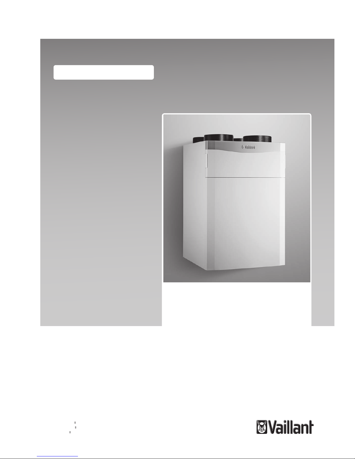
Vaillant recoVAIR VAR 260/4 E, recoVAIR VAR 360/4 E, recoVAIR VAR 260/4, recoVAIR VAR 360/4 Operating Instructions Manual
Page 1
Operating instructions
recoVAIR
VAR 260/4 (E), VAR 360/4 (E)
AT, CH (de), DE
Publisher/manufacturer
Vaillant GmbH
Berghauser Str. 40 D-42859 Remscheid
Tel. +49 21 91 18‑0 Fax +49 21 91 18‑2810
info@vaillant.de www.vaillant.de
Page 2

Contents
2 Operating instructions recoVAIR 0020159950_07
Contents
1 Safety.................................................................... 3
1.1 Action-related warnings......................................... 3
1.2 Intended use.......................................................... 3
1.3 General safety information .................................... 3
2 Notes on the documentation .............................. 5
2.1 Observing other applicable documents ................. 5
2.2 Storing documents................................................. 5
2.3 Validity of the instructions...................................... 5
3 Product description............................................. 5
3.1 Role and function................................................... 5
3.2 Symbols on the product......................................... 6
3.3 Product design....................................................... 6
3.4 Digital Information and Analysis System (DIA)...... 6
3.5 Information on the identification plate.................... 6
3.6 CE label ................................................................. 7
4 Operation.............................................................. 7
4.1 Operating concept ................................................. 7
4.2 Basic display.......................................................... 7
4.3 Operating levels..................................................... 7
4.4 Operator level – overview...................................... 8
4.5 Switching the product on/off .................................. 8
4.6 Setting the ventilation ............................................ 8
4.7 Setting the desired temperature ............................ 9
5 Troubleshooting .................................................. 9
5.1 Detecting and rectifying faults ............................... 9
6 Maintenance and care......................................... 9
6.1 Spare parts .......................................................... 10
6.2 Carrying out maintenance work........................... 10
7 Decommissioning.............................................. 11
7.1 Permanently decommissioning the product......... 11
8 Recycling and disposal..................................... 11
9 Guarantee and customer service ..................... 12
9.1 Guarantee............................................................ 12
9.2 Customer service................................................. 12
Appendix ............................................................................13
A Operator level – overview................................. 13
B Ventilation levels – Overview ........................... 14
C Status messages – Overview ........................... 14
D Maintenance messages – Overview................. 15
E Limp home mode messages – Overview......... 15
F Troubleshooting and fault elimination ............ 15
F.1 Troubleshooting................................................... 15
F.2 Remedy ............................................................... 15
Page 3
Safety 1
0020159950_07 recoVAIR Operating instructions 3
1 Safety
1.1 Action-related warnings
Classification of action-related warnings
The action-related warnings are classified in
accordance with the severity of the possible
danger using the following warning signs and
signal words:
Warning symbols and signal words
Danger!
Imminent danger to life or risk of
severe personal injury
Danger!
Risk of death from electric shock
Warning.
Risk of minor personal injury
Caution.
Risk of material or environmental
damage
1.2 Intended use
There is a risk of injury or death to the user or
others, or of damage to the product and other
property in the event of improper use or use
for which it is not intended.
The product is only intended for aerating and
ventilating living areas. If the product is operated with a heat production source, the heat
production source must be room-sealed. The
remote control must only be used to control
the product. The product must only be operated when the filters are inserted.
The product is not suitable for aerating and
ventilating swimming pool systems. Due to
the high level of exposure to dust, the product
must not be operated during the construction
phase.
Intended use includes the following:
– observance of the operating instructions
included for the product and any other
system components
– compliance with all inspection and main-
tenance conditions listed in the instructions.
This product can be used by children aged
from 8 years and above and persons with
reduced physical, sensory or mental capabilities or lack of experience and knowledge if
they have been given supervision or instruction concerning use of the product in a safe
way and understand the hazards involved.
Children must not play with the product.
Cleaning and user maintenance work must
not be carried out by children unless they are
supervised.
Any other use that is not specified in these
instructions, or use beyond that specified in
this document shall be considered improper
use. Any direct commercial or industrial use
is also deemed to be improper.
Caution.
Improper use of any kind is prohibited.
1.3 General safety information
1.3.1 Danger caused by improper
operation
Improper operation may present a danger to
you and others, and cause material damage.
▶ Carefully read the enclosed instructions
and all other applicable documents, particularly the "Safety" section and the warnings.
▶ Only carry out the activities for which in-
structions are provided in these operating
instructions.
1.3.2 The product must only be installed
and started up by the competent
person
The product must only be properly installed
and started up by a competent person.
1.3.3 Risk of poisoning caused by
simultaneous operation with a heat
production source
If the product is operated at the same time as
a heat production source, life-threatening flue
gas may escape into the rooms from the heat
production source.
▶ Ensure that the competent person has
installed a safety device that monitors the
pressure difference between the living
room and flue system.
Page 4

1 Safety
4 Operating instructions recoVAIR 0020159950_07
1.3.4 Risk of injury and material damage
due to incorrect maintenance and
repairs
▶ Only carry out permitted maintenance work
on the product.
▶ Employ a competent person to carry out all
other maintenance and repair work.
▶ Never carry out repair work on the product
yourself.
▶ Adhere to the maintenance intervals spe-
cified.
1.3.5 Danger due to changes to the
product environment
There is a risk of injury or death to the operator or others, or of damage to the product
and other property, in the event of changes to
the product environment.
▶ Never shut down the safety devices.
▶ Do not tamper with any of the safety
devices.
▶ Do not damage or remove any seals on
components. Only qualified competent
persons and customer service personnel
are authorised to make modifications to
sealed components.
▶ Do not make any changes:
– The product itself
– to the product bypass
– to the pipelines and connections for exit
air, supply air, exhaust air and outside air
– to the condensate discharge
– to the mains connection
▶ Ensure that the mains plug/circuit breaker
(depending on the country) is always accessible after the installation by the competent person and during the entire time
the product is operating.
▶ Do not seal off any air inlets and outlets in
doors, ceilings, windows and walls.
▶ When installing floor coverings, do not
close off or reduce in size the ventilation
openings on the undersides of doors.
▶ If loudspeaker announcements from the
fire brigade/police or radio announcements request that you close windows and
doors, you must switch off the product.
(→ Page 8)
Page 5
Notes on the documentation 2
0020159950_07 recoVAIR Operating instructions 5
2 Notes on the documentation
2.1 Observing other applicable documents
▶ You must observe all operating instructions enclosed with
the system components.
2.2 Storing documents
▶ Keep this manual and all other applicable documents
safe for future use.
2.3 Validity of the instructions
These instructions apply only to:
Product article number
Applicability: Switzerland
Switzerland
VAR 260/4
0010016042
VAR 260/4 E
0010016350
VAR 360/4
0010016041
VAR 360/4 E
0010016351
Product article number
Applicability: Germany
Germany
VAR 260/4
0010016040
VAR 260/4 E
0010016348
VAR 360/4
0010015166
VAR 360/4 E
0010016349
Product article number
Applicability: Austria
Austria
VAR 260/4
0010016040
VAR 260/4 E
0010016348
VAR 360/4
0010015166
VAR 360/4 E
0010016349
3 Product description
This product is a domestic ventilation unit.
3.1 Role and function
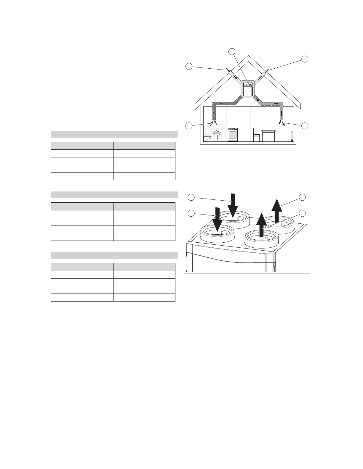
Task
The product aerates and ventilates living spaces and ensures a constant exchange of air with heat recovery in the
building.
Furthermore, the product guarantees the hygienically necessary minimum air exchange and prevents damage to the
building caused by moisture and mould.
Functionality
1
23
4
5
The product (5) is the central component in controlled room
ventilation. Fresh outside air (4) is guided to the living rooms
and bedrooms via air intake openings (2). The used air from
the kitchen, bathroom and WC is guided outside (1) via the
exhaust air openings (3).
4
3
2
1
The exhaust air (2) from the dwelling is guided to the
product. The filter for the exhaust air cleans the exhaust
air and guides the exhaust air to the heat exchanger. The
heat exchanger extracts the heat from the exhaust air (heat
recovery). The cooled air is guided outside as exit air (4).
The outside air (1) is guided to the product from the outside.
The filter for the outside air cleans the outside air and guides
the outside air to the heat exchanger. The heat exchanger
transfers the heat from the exhaust air to the outside air. The
heated air is guided to the dwelling as supply air (3).
On summer nights, the outside temperature is often lower
than the room temperature. Through the automatic bypass,
the cooler outside air is no longer preheated by the heat exchanger. The bypass guides the warmer exhaust air past the
heat exchanger directly outside. The frost protection function
reduces the supply air volume flow according to demand,
which leads to an increase in the exit air temperature. This
prevents the heat exchanger from freezing. If the reduction in
the supply air volume flow is no longer sufficient, the product
switches off.
The humidity sensor records the current moisture in the
exhaust air. If you operate the product in auto mode, the
current air volume flow is regulated according to demand
(aguaCARE.
Page 6

3 Product description
6 Operating instructions recoVAIR 0020159950_07
In the winter, the room air humidity can be perceived as
dry. The optional enthalpy heat exchanger (heat exchanger
with moisture recovery) has the opposite effect (aguaCARE
plus).
3.2 Symbols on the product
Symbol Meaning
Opening for the outdoor-air filter
Opening for the exhaust air filter
3.3 Product design
1
2
3
5
6
7
8
9
4
1 Exit air connection
2 Supply air connection
3 Front casing
4 Front flap
5 Operator control panel
6 Exhaust air filter
7 Outdoor air filter
8 Exhaust air connection
9 Outside air connection
3.3.1 Overview of the operator control elements
278
3
12
1 Fault clearance key
2 Operating buttons
3 Display
3.4 Digital Information and Analysis System
(DIA)
The product is equipped with a Digital Information and Analysis System (DIA system). This system provides information
on the operating status and helps you deal with faults.
278
1
2
3
7
6
5
4
1 Display of the current
air volume flow
2 Display of the current
configuration of the
right-hand selection
button
3 Left- and right-hand
selection buttons
4 "+" button/"-" button
5 Access to the menu for
additional information
6 Display of the current
configuration of the lefthand selection button
7 Display of the symbols
for the active operating
status of the ventilators
Symbol Meaning
Air volume flow:
– Symbol is filled: Air volume flow is greater
– Symbol is empty: Air volume flow is smaller
Heat recovery:
– Permanently on: Heat recovery is switched off
– Permanently off: Heat recovery is active
– Shown in the display: Ventilation active
– Display in the current configuration of the left-
hand selection button: Adjustment range for the
air volume flow
Adjustment range for the desired temperature
F.XXX
Fault in the product: Appears instead of the basic
display, may be an explanatory plain text display
3.5 Information on the identification plate
The identification plate is mounted on the underside of the
product.
Information on the identification plate
Meaning
Read the installation and
maintenance instructions.
VAR 260/4 (E)
VAR 360/4 (E)
Type designation
VAR
Vaillant ventilation unit with
heat recovery
260
360
Max. air volume flow in m3/h
/4 Unit generation
E Enthalpy
P
MAX
Max. power consumption
Page 7

Operation 4
0020159950_07 recoVAIR Operating instructions 7
Information on the identification plate
Meaning
V
MAX
Max. air volume flow
dP
MAX
Delivery pressure at max. air
volume flow
T
MAX
Max. operating temperature
Bar code with serial number,
The 7th to 16th digits of the
serial number form the article
number
3.6 CE label
The CE label shows that the products comply with the basic
requirements of the applicable directives as stated on the
identification plate.
The declaration of conformity can be viewed at the manufacturer's site.
4 Operation
4.1 Operating concept
Operator
control
element
Meaning
(Left-hand
selection
button)
– Setting the air volume flow
– Cancelling the activation of an operating
mode
– Cancelling a change to a set value
– Going one selection level higher
(Right-hand
selection
button)
– Setting the desired temperature
– Activating the operating mode
– Confirm setting
– Going one selection level lower
Press
+
at the same
time
Calling up the menu
/
– Switching back and forth between the menu
items for the entry list
– Decreasing/increasing the set value
Both selection buttons have a soft key function. This means
that their function can be changed.
If the display has been dimmed, the light is switched on by
the first press of the button. In this case, to trigger the button
function, you must press a button again.
The display shows a highlighted selection level, a setting
level or a highlighted value with white font on a black background. A flashing, highlighted value means that you can
change the value.
You always have the option to cancel the change to a setting
and the reading of a value or to exit the selection level by
pressing the left-hand selection button.
If you do not press any buttons for more than 15 minutes,
the display returns to the basic display. Changes that are not
confirmed will not be applied.
4.1.1 Selection level display fields
Menu
Energy yield
Live Monitor
Information
Back Select
1
2
3
4
1 Scrollbar (if more than
three list entries are
available)
2 Current functions of
the right and left-hand
selection buttons (soft
key functions)
3 Selection level list
entries
4 Current function or
selection level
You can use the selection levels to navigate to the display
and setting levels in which you can read or change settings.
The selection levels have four display fields.
In the following, a path name is specified which shows you
how to access a function, e.g. Menu → Information → Con-
tact data.
4.2 Basic display
278
The basic display shows the current condition of the product.
From the basic display, you can directly call up and change
the air volume flow (ventilation) and the desired temperature.
You can access all other functions via the menu.
If there is a fault message, the basic display switches to a
plain text display of the fault message.
From the basic display, you can directly change and read
the most important settings and information by pressing the
selection buttons.
The functions that are available depend on whether a controller is connected to the product.
4.3 Operating levels
The product has two operating levels:
– The operator level shows the most important information
and offers set-up options which do not require any special prior knowledge.
– The installer level must only be operated by persons with
expertise and is therefore protected by a code.
Page 8

4 Operation
8 Operating instructions recoVAIR 0020159950_07
4.4 Operator level – overview
The appendix contains the complete overview of the end
user level. The most important menu points are explained
below.
Operator level – overview (→ Page 13)
4.4.1 Reading the energy yield
Menu → Energy yield →
You can use this function to read the energy yield for the
entire operation.
If a controller is connected, you can also read the energy
yield for the previous day, month and year.
The output figure represents the relationship between recovered and used energy.
4.4.2 Reading the Live Monitor (current status)
Menu → Live Monitor →
You can use the Live Monitor function to read the current
status of the product, the connected components, and the
temperature and parameter values. The display is automatically updated.
4.4.3 Reading contact details
Menu → Information → Contact data
If your competent person has entered their telephone number during the installation, you can read the telephone number under Contact details.
4.4.4 Reading serial and article numbers
Menu → Information → Serial number
You can use this function to read the serial and article number. The article number is found in the second line of the
serial number.
4.4.5 Reading the filter change
Menu → Information → Days until filter chg.
You can use this function to read when the filters have to be
replaced.
4.4.6 Filter change overdue
Menu → Information → Filter chg. overdue
You can use this function to read by how long the filter
change is overdue.
4.4.7 Reading the maintenance interval
Menu → Information → Days until maint.
You can use this function to read when you should have your
product serviced.
4.4.8 Maintenance interval overdue
Menu → Information → Maintenance overdue
You can use this function to read by how long the maintenance for your product is overdue.
4.4.9 Setting the language
Menu → Basic settings → Language
You can use this function to change the language settings
for your product.
4.4.10 Set display contrast
Menu → Basic settings → Display contrast
You can use this function to set the display contrast.
4.4.11 Setting the heat recovery
Menu → Basic settings → Heat recovery
You can use this function to set the heat recovery.
– Auto heat recovery (recommended): The bypass is auto-
matically closed/opened depending on the outside temperature.
– Heat recovery on: The bypass is closed.
– Heat recovery off: The bypass is open.
4.5 Switching the product on/off
The mains plug/circuit breaker (depending on the country)
must remain accessible after the installation by the competent person and during the entire time the product is operating.
4.5.1 Switching on the product
▶ Plug the product's mains plug into the earthed plug
socket (230 V) or use the circuit breaker (depending on
the country) to switch on the product.
◁ The product's electronics start up.
◁ The basic display appears on the display.
4.5.2 Switching off the product
▶ Pull the product's mains plug out of the earthed plug
socket (230 V) or use the circuit breaker (depending on
the country) to switch off the product.
4.6 Setting the ventilation
4.6.1 Setting the ventilation on the product
1.
Alternatives 1 / 2
▶
Press in the basic display.
▶
Use and to select the desired ventilation level.
– Adjustment range: Nominal ventilation, In-
creased ventil., Reduced ventilation, Auto
Ventilation levels – Overview (→ Page 14)
▶
Confirm by pressing .
1.
Alternatives 2 / 2
▶
Press in the basic display.
▶
Press .
▶
Use and to select the desired ventilation level.
Page 9

Troubleshooting 5
0020159950_07 recoVAIR Operating instructions 9
– Adjustment range: Intens. ventilation On, In-
tens. ventilation Off
Ventilation levels – Overview (→ Page 14)
▶
Confirm by pressing .
4.6.2 Setting the ventilation at the step switch
Conditions: Step switch connected
6
5
4
3
1
2
1 Maintenance indicator
2 Rotary switch
3 Increased ventilation
4 Nominal ventilation
5 Automatic ventilation
6 Reduced ventilation
▶ Use the step switch to set the ventilation level (optional
accessory).
Ventilation levels – Overview (→ Page 14)
Note
The maintenance display (1) lights up if the
product requires a filter change or general
maintenance, or if a fault is present.
4.6.3 Setting the ventilation at the control
Conditions: Controller connected
▶ Navigate to the corresponding menu in the control and
set the ventilation level (→ Control operating instructions).
Ventilation level
Proportion of the nominal ventilation
1)
0 40 %
1 70 %
2 80 %
3 90 %
4 100 %
5 110 %
6 120 %
7 130 %
1)
The nominal ventilation is the normal operating mode with
normal loading of the room air and a normal number of
people.
4.7 Setting the desired temperature
Conditions: Controller connected, No boiler connected
OR: No controller connected, No other units connected (only recoVAIR is
available)
▶
Press in the basic display.
▶
Use and to select the desired
temperature.
– Adjustment range: 16 … 28 ℃
▶
Confirm by pressing .
5 Troubleshooting
5.1 Detecting and rectifying faults
Danger!
Risk of death from electric shock!
Risk of death from electric shock when working on live connections (230 V).
▶ Before carrying out any work on the
product, pull the product's mains plug
out of the earthed plug socket or use the
circuit breaker (depending on the country)
to switch off the product's power supply.
▶ Secure the power supply against being
switched on again.
▶ Check that there is no voltage in the con-
nections.
▶ If faults or fault messages (F.XXX) or limp home mode
messages (Lhm.XXX) occur, proceed in accordance with
the tables in the appendix.
▶ If the product is not functioning correctly, contact a com-
petent person.
6 Maintenance and care
Danger!
Risk of death from electric shock!
Risk of death from electric shock when working on live connections (230 V).
▶ Before carrying out any work on the
product, pull the product's mains plug
out of the earthed plug socket or use the
circuit breaker (depending on the country)
to switch off the product's power supply.
▶ Secure the power supply against being
switched on again.
▶ Check that there is no voltage in the con-
nections.
An annual inspection and biennial maintenance of the
product carried out by a competent person is a prerequisite
for ensuring that the product is permanently ready and
safe for operation, reliable, and has a long service life. The
Page 10

6 Maintenance and care
10 Operating instructions recoVAIR 0020159950_07
inspection may require maintenance to be carried out earlier,
depending on the results.
6.1 Spare parts
All spare parts that are used must be Original Vaillant spare
parts.
Original Vaillant spare parts are available from your heating
specialist company.
6.2 Carrying out maintenance work
▶ Only carry out the maintenance work that is listed in the
operating instructions.
▶ Observe the displayed maintenance messages and
measures in accordance with the table in the appendix.
▶ Switch off the product before carrying out any mainten-
ance work. (→ Page 8)
▶ Switch on the product after carrying out any maintenance
work. (→ Page 8)
▶ Ensure that all other maintenance work that is not listed
here is carried out by a competent person.
6.2.1 Caring for the product
Caution.
Risk of material damage caused by un-
suitable cleaning agents.
▶ Do not use sprays, scouring agents, de-
tergents, solvents or cleaning agents that
contain chlorine.
▶ Clean the casing with a damp cloth and a little solvent-
free soap.
6.2.2 Cleaning the supply and exhaust air valves
▶ Clean the supply and exhaust air valves in the living
areas (→ Instructions for valves).
6.2.3 Maintaining the filters
Removing the filters
3
2
1
4
1. Remove the front flap (4) by pushing the recessed
handle.
2. Pull out both of the filter plugs (3).
3. Pull the outdoor air filter (1) and the exhaust-air filter (2)
out of the product.
4. Check the filters for dirt.
– Recommended check: Every three months
1 / 2
Degree of contamination: Filter is lightly soiled
Caution.
Risk of material damage caused by
incorrect cleaning of the filter.
Water and other liquids may damage the
filters and the product.
▶ Only clean the filters with a vacuum
cleaner.
▶ Clean the filters.
– Vacuum cleaner at a low setting
2 / 2
Degree of contamination: Filter is heavily soiled
Operating days: ≥ 182 d
Replacement interval reached: At least twice annually
▶ Replace the filters in the system.
– Exhaust-air filter class: G4 (in accordance
with EN 779)/ISO Coarse (in accordance with
ISO 16890)
– Outdoor-air filter class: F7 or F9 (in ac-
cordance with EN 779)/ISO ePM2,5 65%
or ISO ePM1,0 85% (in accordance with
ISO 16890)
– Exhaust air valve filter
Installing the filters
5. Install the filters in the product and ensure that they are
correctly aligned as you do so.
– Labelling on the filters and slot positions
6. Place the filter plugs on the filters.
Resetting the filter days
7. Switch on the product. (→ Page 8)
8.
Press the + buttons simultaneously to access the menu.
9. Navigate to the Resets → Res. days until fil. ch. menu.
10. Reset the filter days.
11.
Press the button to exit the menu.
12. Secure the front flap.
6.2.4 Cleaning the condensate siphon
Note
Wear gloves and avoid contact with the skin and
eyes.
1. Check the condensate siphon for dirt each time you
change the filter.
Condensate siphon contaminated
▶ Remove the condensate siphon from the product.
▶ Clean the condensate siphon.
Page 11

Decommissioning 7
0020159950_07 recoVAIR Operating instructions 11
Connecting the condensate siphon/dry siphon and
condensate drain pipework
2. Connect the condensate siphon/dry siphon to the
product (→ Installation instructions for the condensate
siphon/dry siphon, accessories).
– Condensate discharge pipe downward gradient
(descending from the product): > 5°
min. 20
1
A
B
Danger!
Risk of damage to health caused by incor-
rectly connected condensate drain pipework!
In the interests of hygiene, the condensate
drain pipework must not be directly connected to the waste-water piping.
▶ Connect the condensate discharge to the
second siphon.
Caution.
Risk of material damage caused by con-
densate.
If a condensate discharge pipe has been connected incorrectly, a build-up of condensate
and uncontrolled condensate drainage may
damage the product. Furthermore, the condensate may leak out of the product and onto
the floor.
▶ Install a drip distance of min. 20 mm
between the outlet for the condensate
drain pipework and the second siphon.
▶ Note the downward gradient for the con-
densate discharge pipe (> 5°).
3. Connect the condensate drain pipework to the second
siphon while taking into consideration the drip distance
(1).
– Drip distance: ≥ 20 mm
4. Fill the condensate siphon/dry siphon with water.
6.2.5 Establish system efficiency
1. Clean the supply and exhaust air valves and their corresponding filters. (→ Page 10)
2. Check whether any obstructions are impeding the air
flows.
3. Clean the outside air's intake tract and the exit air's
outlet openings.
4. Carry out maintenance on the product filter.
(→ Page 10)
5. Remove the front flap if this has not yet been done.
6. Switch the product on if this has not already been done.
(→ Page 8)
7. Press the reset button.
◁ Maintenance message M.802 is no longer shown in
the display. No other measures are required.
▽ Maintenance message M.802 is still being shown in
the display.
▶ Inform a competent person.
8. Secure the front flap.
7 Decommissioning
7.1 Permanently decommissioning the product
▶ Have a competent person permanently decommission
the product.
8 Recycling and disposal
Disposing of the packaging
▶ The competent person who installed your product is re-
sponsible for the disposal of the packaging.
Disposing of the product and accessories
▶ Do not dispose of the product or the accessories (apart
from the filters) with household waste.
▶ Ensure that the product and all accessories are disposed
of properly.
▶ Dispose of used filters with household waste.
▶ Observe all relevant regulations.
Page 12

9 Guarantee and customer service
12 Operating instructions recoVAIR 0020159950_07
9 Guarantee and customer service
9.1 Guarantee
Applicability: Switzerland
Werksgarantie gewähren wir nur bei Installation durch einen
anerkannten Fachhandwerksbetrieb. Dem Eigentümer des
Geräts räumen wir eine Werksgarantie entsprechend den
landesspezifischen Vaillant Geschäftsbedingungen und den
entsprechend abgeschlossenen Wartungsverträgen ein.
Garantiearbeiten werden grundsätzlich nur von unserem
Werkskundendienst ausgeführt.
Applicability: Germany
OR Austria
Herstellergarantie gewähren wir nur bei Installation durch
einen anerkannten Fachhandwerksbetrieb.
Dem Eigentümer des Geräts räumen wir diese Herstellergarantie entsprechend den Vaillant Garantiebedingungen
ein. Garantiearbeiten werden grundsätzlich nur von unserem
Kundendienst ausgeführt. Wir können Ihnen daher etwaige
Kosten, die Ihnen bei der Durchführung von Arbeiten an
dem Gerät während der Garantiezeit entstehen, nur dann
erstatten, falls wir Ihnen einen entsprechenden Auftrag erteilt
haben und es sich um einen Garantiefall handelt.
9.2 Customer service
Applicability: Austria
Vaillant Group Austria GmbH
Clemens-Holzmeister-Straße 6
1100 Wien
Österreich
E-Mail Kundendienst: termin@vaillant.at
Internet Kundendienst: http://www.vaillant.at/werkskundendienst/
Telefon: 05 7050‑2100 (zum Regionaltarif österreichweit, bei
Anrufen aus dem Mobilfunknetz ggf. abweichende Tarife nähere Information erhalten Sie bei Ihrem Mobilnetzbetreiber)
Der flächendeckende Kundendienst für ganz Österreich ist
täglich von 0 bis 24 Uhr erreichbar. Vaillant Kundendiensttechniker sind 365 Tage für Sie unterwegs, sonn- und feiertags, österreichweit.
Applicability: Switzerland
Vaillant GmbH (Schweiz, Suisse, Svizzera)
Riedstrasse 12
CH-8953 Dietikon
Schweiz, Svizzera, Suisse
Kundendienst: 044 74429‑29
Techn. Vertriebssupport: 044 74429‑19
Applicability: Germany
Auftragsannahme Vaillant Kundendienst: 021 91 5767901
Page 13

Appendix
0020159950_07 recoVAIR Operating instructions 13
Appendix
A Operator level – overview
Setting level Values Unit Increment, select Default
setting
Min. Max.
Menu → Energy yield →
Energy yield: Today Current value kWh
En. yield: Prev. day Current value kWh
Energy yield: Month Current value kWh
Energy yield: Year Current value kWh
Energy yield: Total Current value kWh
Output figure Current value
Menu → Live Monitor →
Status Current value
Frost prot. element Current value
Heat recovery Current value
Power efficiency Current value
Wh/m
3
Exhaust air temp. Current value ℃
Exhaust air humidity Current value % rel.
Supply air temp. Current value ℃
Outside air temp. Current value ℃
Supply air targ. val. Current value m³/h
Menu → Information →
Contact data Phone number
Serial number Permanent
value
Days until filter chg. Current value d
Filter chg. overdue Current value d
Days until maint. Current value d
Maintenance overdue Current value d
Menu → Basic settings →
Language Current lan-
guage
Languages available for selection English
Display contrast Current value 1 25
15 40
Heat recovery Current value OFF, ON, Auto Auto
Menu → Resets →
Res. days until fil. ch. Yes, No No
Page 14

Appendix
14 Operating instructions recoVAIR 0020159950_07
B Ventilation levels – Overview
Ventilation
level
Meaning
Automatic
ventilation
(recommended)
The relative humidity in the extract air is continuously measured and the volume flow is
adapted to the current requirement. This setting can be used throughout the entire year.
Nominal ventilation
The nominal ventilation is the normal operating mode at normal loading of the room air
and a normal number of people.
Reduced ventilation
Reduced ventilation should be selected if you
will be absent for an extended period of time
in order to reduce the energy consumption.
Increased
ventilation
Increased ventilation should be selected
for increased loading of the room air. For
example, if there is an increased number of
people or for activities such as cooking, etc.
Ventilation
boost (can only
be set using
the control
elements on
the product or
the control)
Ventilation boost should be selected if there is
temporarily increased load. Ventilation boost
is activated for 30 minutes, after which the
product automatically switches back to the
operating mode that was previously set.
C Status messages – Overview
Statuscode Meaning
S.800 Frost prot. element active
The frost protection element is activated at outside temperatures below −3 °C in order to prevent the
product from freezing.
S.802 Heat recovery active The bypass is closed. Heat is recovered via the heat exchanger.
S.803 Heat recovery not active
The bypass is open. The rooms are passively cooled.
S.804 Heat recovery 50% The bypass is half-open. The rooms are also passively cooled. However, part of the volume flow is
guided through the heat exchanger in order to prevent supply air being too cool.
S.805 Automatic mode The ventilation of the rooms depends on the moisture in the rooms. The more moisture there is, the
more intensive the ventilation. If the optional CO2sensors (carbon dioxide) are installed, the CO2content is taken into consideration.
S.806 Manual mode The product is operated at the selected ventilation level. This is set using the control elements on the
product, the step switch or an optional control.
S.807 Intens. ventilation Intensive ventilation has been activated.
S.808 Calibration Calibration mode has been activated.
S.809 Check programme or
sensor/actuator test active
A check programme or sensor/actuator test has been activated.
S.810 Days away from home
active
Days away from home mode has been activated.
S.811 Moisture protection
active
The moisture protection function has been activated. This is sometimes activated by functions of the
limp home mode.
S.812 Standard frost prot.
active
The standard frost protection function has been activated. The supply air ventilator is down-regulated,
depending on the outside temperature, in order to prevent the product from freezing.
S.813 Cut-off protection bypass active
The automatic bypass cut-off protection has been activated.
S.814 Intensive ventilation
overrun
A phase with nominal ventilation always follows an intensive ventilation phase.
S.815 System off Frost protection active
The product is switched off at low temperatures in order to prevent the product from freezing.
Page 15

Appendix
0020159950_07 recoVAIR Operating instructions 15
D Maintenance messages – Overview
# Message Description Maintenance work Interval
1 M.800 Filter
change
The maintenance interval for
the filters was exceeded.
Maintaining the filters At least twice annually
10
2 M.801 Mainten-
ance
The maintenance interval for
the product was exceeded.
Have the maintenance work
carried out on the product by a
competent person
At least annually
3 M.802 System ef-
ficiency impaired
The system efficiency is adversely affected.
Establish system efficiency As required
11
E Limp home mode messages – Overview
Message Possible cause Measure
Lhm.806 Supply air temp. too
low
Frost protection active ▶ Wait until the supply-air temperature increases again. The
product then starts normal operation.
Supply air temp.: > 10 ℃
F Troubleshooting and fault elimination
F.1 Troubleshooting
Symptom Possible cause Measure
Product not operating The mains voltage has been
interrupted/power cut
▶ Wait until the mains voltage has been re-established and the
product automatically switches on (all settings are retained).
Frost protection active (mains
voltage present)
1. Check whether S.815 is displayed in the Live Monitor.
2. Wait until the outside temperature increases (the product
automatically switches on no later than 60 minutes after the
temperature increases.).
– Outside temperature: > −3 ℃
Product has a reduced air flow Filter slightly dirty ▶ Clean the filters.
Filter heavily dirty ▶ Replace the filter.
Supply-air temperature too low ▶ Wait until the supply-air temperature increases again. The
product then starts normal operation.
Supply air temp.: > 10 ℃
Outside temperature too low 1. Check whether S.812 is displayed in the Live Monitor.
2. Wait until the outside temperature increases again. The
product then starts normal operation.
– Outside temperature: > −3 ℃
Product with increased noise
level
Filter slightly dirty ▶ Clean the filters.
Filter heavily dirty ▶ Replace the filter.
Product with bad/unpleasant air Filter heavily dirty ▶ Replace the filter.
F.2 Remedy
Message Possible cause Measure
F.801 Frost protection not
guaranteed
Heat exchanger protection is
active
▶ Wait until the outside temperature increases (the product auto-
matically switches on no later than 60 minutes after the temperature increases.).
Outside temperature: > −3 ℃
F.804 Supply air temp. too
low
Bypass does not work/is defective
1. Press the fault clearance key.
– Fault clearance attempts: ≤ 3
2. If the fault cannot be eliminated with the fault clearance attempt, inform a competent person.
Heat exchanger does not
work/is defective
1. Press the fault clearance key.
– Fault clearance attempts: ≤ 3
2. If the fault cannot be eliminated with the fault clearance attempt, inform a competent person.
Page 16

0020159950_07 12.07.2017
Supplier
Vaillant Deutschland GmbH & Co.KG
Berghauser Str. 40 D-42859 Remscheid
Telefon 021 91 18‑0 Telefax 021 91 18‑2810
Auftragsannahme Vaillant Kundendienst 021 91 5767901
info@vaillant.de www.vaillant.de
Vaillant Group Austria GmbH
Clemens-Holzmeister-Straße 6 1100 Wien
Telefon 05 7050 Telefax 05 7050‑1199
Telefon 05 7050‑2100 (zum Regionaltarif österreichweit, bei Anrufen aus dem Mobilfunknetz ggf. abweichende
Tarife - nähere Information erhalten Sie bei Ihrem Mobilnetzbetreiber)
info@vaillant.at termin@vaillant.at
www.vaillant.at www.vaillant.at/werkskundendienst/
Vaillant GmbH (Schweiz, Suisse, Svizzera)
Riedstrasse 12 CH-8953 Dietikon
Tel. 044 74429‑29 Fax 044 74429‑28
Kundendienst 044 74429‑29 Techn. Vertriebssupport 044 74429‑19
info@vaillant.ch www.vaillant.ch
© These instructions, or parts thereof, are protected by copyright and may be reproduced or distributed only with
the manufacturer's written consent.
We reserve the right to make technical changes.
0020159950_07
 Loading...