


Operating instructions
multiMATIC
VRC 700/5
BE (fr), CH (fr), FR
Publisher/manufacturer
Vaillant GmbH
Berghauser Str. 40 D-42859 Remscheid
Tel. +49 21 91 18‑0 Fax +49 21 91 18‑2810
info@vaillant.de www.vaillant.de

Contents
2 Operating instructions multiMATIC 0020255037_00
Contents
1 Safety .................................................................... 3
1.1 Action-related warnings ......................................... 3
1.2 Intended use.......................................................... 3
1.3 General safety information .................................... 3
1.4 Recycling and disposal.......................................... 3
2 Notes on the documentation .............................. 5
2.1 Observing other applicable documents ................. 5
2.2 Storing documents................................................. 5
2.3 Validity of the instructions ...................................... 5
2.4 Nomenclature ........................................................ 5
2.5 Function availability ............................................... 5
3 Product description............................................. 5
3.1 Design of the product............................................. 5
3.2 Main function ......................................................... 5
3.3 Zones..................................................................... 6
3.4 Hybrid manager ..................................................... 6
3.5 Frost protection function ........................................ 6
3.6 Preventing malfunctions ........................................ 6
3.7 Identification plate.................................................. 6
3.8 Serial number ........................................................ 6
3.9 CE label ................................................................. 6
4 Operation.............................................................. 6
4.1 Operating structure................................................ 6
4.2 Basic display.......................................................... 7
4.3 Operating concept ................................................. 8
5 Operating and display functions...................... 10
5.1 Information........................................................... 10
5.2 Settings................................................................ 12
5.3 Operating modes ................................................. 16
5.4 Advanced functions ............................................. 17
5.5 Messages ............................................................ 18
6 Troubleshooting ................................................ 18
6.1 Temporarily setting limp home mode .................. 18
7 Care..................................................................... 19
7.1 Caring for the product .......................................... 19
8 Decommissioning.............................................. 19
8.1 Decommissioning the product ............................. 19
8.2 Recycling and disposal........................................ 19
9 Guarantee and customer service..................... 19
9.1 Guarantee............................................................ 19
9.2 Customer service................................................. 20
10 Technical data.................................................... 20
10.1 Product data in accordance with EU
Ordinance no. 811/2013, 812/2013 ..................... 20
Appendix ............................................................................21
A Overview of the operating and display
functions............................................................. 21
A.1 Operating modes ................................................. 21
A.2 End user level ...................................................... 21
B Troubleshooting ................................................ 25
C Maintenance messages .................................... 25
Index ...................................................................................27

Safety 1
0020255037_00 multiMATIC Operating instructions 3
1 Safety
1.1 Action-related warnings
Classification of action-related warnings
The action-related warnings are classified in
accordance with the severity of the possible
danger using the following warning signs and
signal words:
Warning symbols and signal words
Danger!
Imminent danger to life or risk of
severe personal injury
Danger!
Risk of death from electric shock
Warning.
Risk of minor personal injury
Caution.
Risk of material or environmental
damage
1.2 Intended use
In the event of inappropriate or improper use,
damage to the product and other property
may arise.
The product is intended for using an eBUS
interface to control a heating installation with
heat generators from the same manufacturer.
Intended use includes the following:
– observance of the operating instructions
included for the product and any other
system components
– compliance with all inspection and main-
tenance conditions listed in the instructions.
This product can be used by children aged
from 8 years and above and persons with
reduced physical, sensory or mental capabilities or lack of experience and knowledge if
they have been given supervision or instruction concerning use of the product in a safe
way and understand the hazards involved.
Children must not play with the product.
Cleaning and user maintenance work must
not be carried out by children unless they are
supervised.
Any other use that is not specified in these
instructions, or use beyond that specified in
this document shall be considered improper
use. Any direct commercial or industrial use
is also deemed to be improper.
Caution.
Improper use of any kind is prohibited.
1.3 General safety information
1.3.1 Danger caused by improper
operation
Improper operation may present a danger to
you and others, and cause material damage.
▶ Carefully read the enclosed instructions
and all other applicable documents, particularly the "Safety" section and the warnings.
▶ Only carry out the activities for which in-
structions are provided in these operating
instructions.
1.3.2 Moisture and mould damage due to
inadequate exchange of air
In heavily insulated rooms that only allow a
small exchange of air, moisture and mould
damage may occur.
▶ Ventilate the rooms regularly by open-
ing windows and activate the Ventilation
boost function once to save energy.
Conditions: Ventilation unit is connected
▶ Do not disconnect the ventilation unit from
the power grid.
▶ Clean and service the ventilation unit in
accordance with the instructions for the
ventilation unit.
1.4 Recycling and disposal
▶ The competent person who installed your
product is responsible for the disposal of
the packaging.
If the product is labelled with this mark:
▶ In this case, do not dispose of the product
with the household waste.
▶ Instead, hand in the product to a collection
centre for waste electronic or electrical
equipment.
If the product contains batteries that are
labelled with this mark, these batteries may

1 Safety
4 Operating instructions multiMATIC 0020255037_00
contain substances that are hazardous to
human health and the environment.
▶ In this case, dispose of the batteries at a
collection point for batteries.

Notes on the documentation 2
0020255037_00 multiMATIC Operating instructions 5
2 Notes on the documentation
2.1 Observing other applicable documents
▶ You must observe all operating instructions enclosed with
the system components.
2.2 Storing documents
▶ Keep this manual and all other applicable documents
safe for future use.
2.3 Validity of the instructions
These instructions apply only to:
VRC 700/5 – article number
Belgium
0020171315
France
0020171315
Switzerland
0020171315
2.4 Nomenclature
The following terms are used for simplification:
– Control: If this refers to the VRC 700 control.
– Remote control: If this refers to the VR 91 remote control.
2.5 Function availability
Note
The functions described in these operating instructions are not available for all system configurations.
The controller only shows the functions that are available in
the system configuration you have installed.
3 Product description
3.1 Design of the product
1
2
3
4
5
6
5
1 Display
2 Wall-mounting base
3 Diagnostics socket
4 Wall-mounting base
cover
5 Selection button
6 Rotary knob
3.2 Main function
The control is a weather compensator with an outdoor temperature sensor that is fitted in the open air.
The control is connected to the outdoor temperature sensor
and the heat generator. The control controls the heating
installation and other connected components, e.g. the domestic hot water generation for a connected domestic hot
water cylinder or the ventilation of a connected ventilation
unit.
3.2.1 Heating
The outdoor temperature sensor measures the outdoor temperature and forwards the values to the control. When the
outside temperature is low, the controller increases the flow
temperature of the heating installation. If the outdoor temperature increases, the control reduces the flow temperature.
The control responds to the fluctuations in the outdoor temperature and uses the flow temperature to ensure that the
room temperature remains at the required temperature.
3.2.2 Cooling
The room temperature sensor measures the room temperature and sends the data to the controller. If the room temperature is higher than the desired temperature that is set, the
controller switches cooling on.
3.2.3 Ventilation
Using a controlled exchange of air, the ventilation unit ensures that the living rooms are ventilated and aerated. The
control controls the air volume flow via the ventilation levels
that are set.

4 Operation
6 Operating instructions multiMATIC 0020255037_00
3.2.4 Hot water generation
A temperature sensor measures the temperature of the water in the domestic hot water cylinder and forwards the values to the control. At a low domestic hot water temperature,
the control increases the temperature in the domestic hot
water circuit and thus heats the water in the domestic hot
water cylinder to the set domestic hot water temperature.
3.2.5 Circulation
If a circulation pump is installed in the heating installation,
the draw-off points will provide hot water more quickly. The
circulation pump pumps hot water through the secondary
return pipes in the circuit and to the draw-off points.
3.3 Zones
A building is divided into several zones if the heat demand
differs between different sections of the building.
– If underfloor heating and radiator heating are installed in
a house.
– If a house contains more than one independent residen-
tial unit.
If more than one zone is available, the controller controls the
available zones.
3.4 Hybrid manager
If you have connected a heat pump, the hybrid manager
attempts to cover the declared energy requirement under
the considerations of the cost optimisation and the technical
conditions.
Note
To ensure that the heat pump and the boiler can
work effectively and in synch with one another,
the tariffs (→ Page 15) must be set correctly. If
the tariffs are set incorrectly, this may result in
increased costs.
If the system declares an energy requirement, the hybrid
manager switches on and forwards the energy requirement
to the heat generator. The hybrid manager decides which
heat generator to operate based on the tariffs that are set in
relation to the energy requirement.
3.5 Frost protection function
The frost protection function protects the heating system and
apartment from frost damage. The frost protection function
monitors the outside temperature.
If the outside temperature
– falls below 4 °C, the controller switches the heat gener-
ator on after a frost protection delay time, and brings the
target room temperature to 5 °C.
– rises above 5 °C, the controller does not switch the heat
generator on but monitors the outside temperature.
Note
The competent person can set the frost protection
delay time.
3.6 Preventing malfunctions
▶ Ensure that air can circulate freely around the controller,
and that the controller is not covered by furniture, curtains or other objects.
▶ Ensure that all radiator valves in the room where the con-
troller is fitted are fully open.
3.7 Identification plate
The identification plate is located inside the product and is
not accessible from the outside.
3.8 Serial number
You can call up the serial number to the display under Menu
→ Information → Serial number. The 10-digit article number
is located in the second line.
3.9 CE label
The CE label shows that the products comply with the basic
requirements of the applicable directives as stated on the
identification plate.
The declaration of conformity can be viewed at the manufacturer's site.
4 Operation
4.1 Operating structure
4.1.1 Adjustment and display levels
The product has two adjustment and display levels.
The end user level contains information and setting options
that you require as the end user.
The installer level is reserved for the competent person. It is
protected by a code. Only competent persons may change
any settings in the installer level.
Operating levels (→ Page 21)
4.1.2 Menu structure design
The menu structure consists of several selection levels and a
setting level.
You can always use the selection button Menu to access
selection level 1 from the basic display.
You can use the selection button Op. mode to directly access the setting level Operating mode.
The lowest level is always the setting level.

Operation 4
0020255037_00 multiMATIC Operating instructions 7
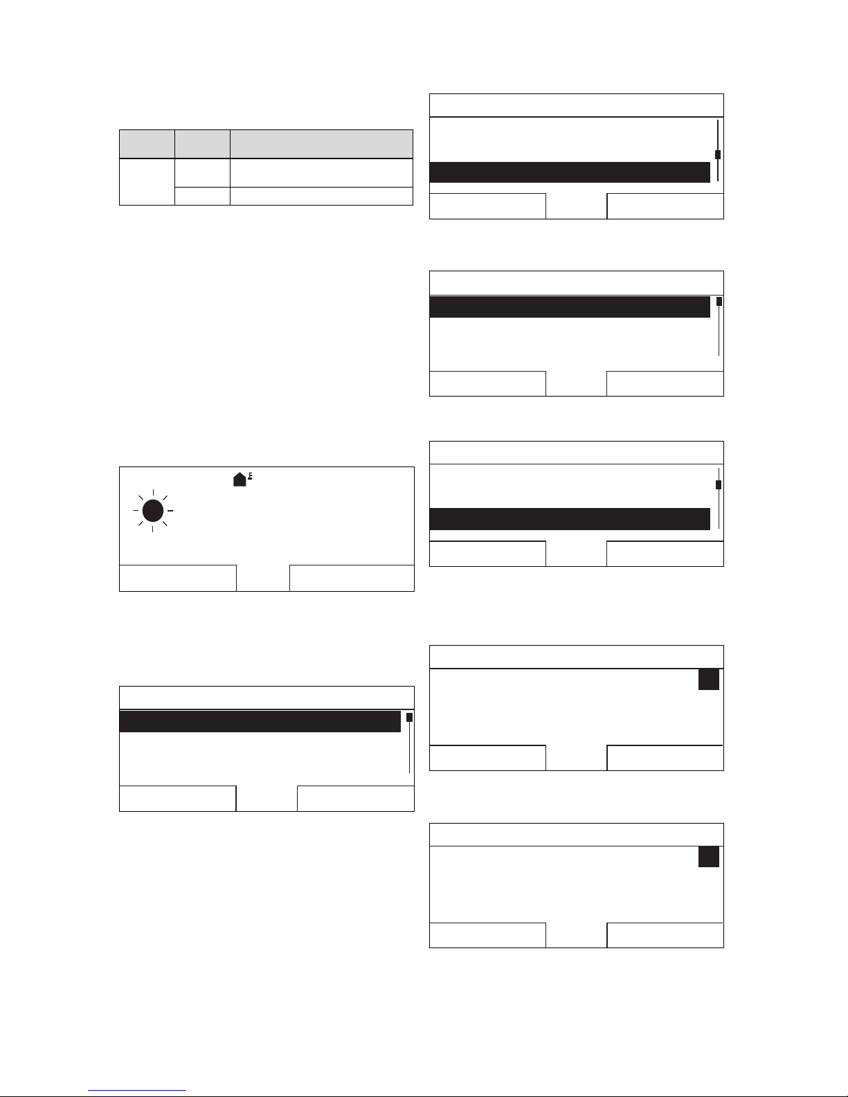
4.1.3 Selection level
Menu
Information
Desired temperatures
Timer programmes
Back
Select
1
4
3
2
1 Scroll bar
2 Current functions of the
selection buttons
3 Selection level list
entries
4 Current function or
selection level
The scroll bar (1) only appears if there are more list entries
than can be shown at once on the display.
4.1.4 Setting level
Zone 1
Set-back temp. heat.Set-back temp. heat.
Day temp. coolingDay temp. cooling
Day temp. heatingDay temp. heating
Back
Change
20.0 °C20.0 °C
26.0 °C26.0 °C
15.0 °C15.0 °C
21
3
5
4
1 Current selection
2 Current selection level
3 Values
4 Current functions of the
selection buttons
5 Setting level
In the setting level, you can select the values you want to
read or change.
4.1.5 Soft key function for the selection buttons
Both selection buttons have a soft key function, i.e. different
functions may be assigned to the selection buttons. If, for example, you press the left-hand selection button, the current
function switches from Menu to Back.
4.2 Basic display
Auto
5,0°C
°C
19,5
15:34
Desired heating temp. 20,0°C
Menu
Op. mode
1
3
4
5
9
8
6
7
2
1 Symbol for outdoor
temperature
2 Outdoor temperature
3 Room temperature (for
wall-mounting only)
4 Time
5 Function of the right-
hand selection button
6 Function of the left-hand
selection button
7 Desired setting
8 Symbol for Auto operat-
ing mode
9 Mode for the current
operating mode
The basic display appears:
– Depending on which level you are in, you must press the
left-hand selection button several times.
– If the control is in a selection level or setting level and
you do not operate the control for more than 5 minutes.
4.2.1 Preferred zone in the basic display
If your heating installation has several zones, the competent
person sets the zone whose values are to appear in the basic display.
4.2.2 Preferred operating mode in the basic
display
If your heating installation is designed for two of the three
operating modes (heating, cooling or ventilating), you can
switch the basic display to the required operating mode. Depending on the selected operating mode and the mode in
which the operating mode is found, various information may
appear in the basic display.
4.2.3 Information in the basic display
The basic display shows the most important current settings
and values for the heating installation.
Various information may appear in the basic display. It
depends on which operating mode you select and which
settings you have implemented for the selected operating
mode.
4.2.3.1 Basic display for the Heating operating
mode
Mode Time
periods
Symbol Desired setting
Auto On
Desired heating temp.
appears:
– The control maintains
the temperature at the
desired level.
Empty line appears:
– The control does not
request any heating
energy.
Off
Day
Set-back
off Empty line

4 Operation
8 Operating instructions multiMATIC 0020255037_00
4.2.3.2 Basic display for the Cooling operating
mode
Mode Time
periods
Symbol Desired setting
Auto On Desired cooling temp.
Off Empty line
Day Desired cooling temp.
off Empty line
4.2.3.3 Basic display for the Ventilation operating
mode
Mode Time
periods
Symbol Desired setting
Auto On Max. vent. stage
Off Max. vent. stage
Day Ventilation stage
Set-back Ventilation stage
4.2.3.4 Basic display for the Manual cooling
advanced function
Mode Time periods Desired setting
Activated On Desired cooling temp.
Off Empty line
4.3 Operating concept
The controller is operated using two selection buttons and a
rotary knob.
You can use the selection buttons to do the following:
– Navigate through the selection levels and the setting
level in the menu structure.
– Select a set value.
– Confirm a set value.
– Navigate to the operating modes.
– Cancel changing a set value.
You can use the rotary knob to do the following:
– Navigate through the list entries for a selection level.
– Select a selection level or setting level.
– Change a selected set value.
The display shows an element that is highlighted by white
writing on a black background. A flashing, highlighted value
means that you can change the value.
If you do not operate the control for more than 10 seconds,
the background lighting switches off.
If you do not operate the control for more than 60 seconds,
the control becomes inoperative and dashes (--) appear on
the display instead of values.
If you do not operate the controller during a period of more
than 5 minutes, the basic display appears again.
4.3.1 Using the rotary knob to make settings in
the basic display
If the display shows the basic display, you can use the rotary
knob to change the desired setting.
The setting that you change depends on the selected basic
display, operating mode and the set mode for the operating
mode.
4.3.1.1 Changing the desired setting in the Heating
operating mode
OK
Desired day temperature
Only today: 18 °C
For long-term change,
press OK
Mode Time
periods
Effect
Auto On Switch to another display view with the
request:
– Permanent change to the Day
temp. heating
– Change to the Day temp. heating
for six hours
Off Direct change to the Set-back temp.
heat. for six hours
Day Switch to another display view with the
request:
– Permanent change to the Day
temp. heating
– Change to the Day temp. heating
for six hours
Set-back Direct change to the Set-back temp.
heat. for six hours
off None
4.3.1.2 Changing the desired setting in the Cooling
operating mode
Mode Time
periods
Effect
Auto On Direct permanent change to the Day
temp. cooling
Off None
Day Direct permanent change to the Day
temp. cooling
off None
4.3.1.3 Changing the desired setting in the
Ventilation operating mode
Mode Time
periods
Effect
Auto On Direct permanent change to the Max.
vent. stage: Day
Off Direct permanent change to the Max.
vent. stge: Night
Day Direct permanent change to the Max.
vent. stage: Day
Set-back Direct permanent change to the Max.
vent. stge: Night
Operation 4
0020255037_00 multiMATIC Operating instructions 9
4.3.1.4 Changing the desired setting in the Manual
cooling advanced function
Mode Time
periods
Effect
Activated On Direct permanent change to the Day
temp. cooling
Off None
4.3.1.5 Using the rotary knob to make settings with
no effect
You cannot influence the following advanced functions by
turning the rotary knob:
– System OFF active
– Cylinder boost
– Party function
– 1 day at home
– Days at home scheduling
– 1 day away from home
– Days away from home scheduling
– Ventilation boost
– Screed-drying function
4.3.2 Example, changing the display contrast
Auto
5.0 °C
°C
19.5
15:34
Desired heating temp. 20.0 °C
Menu
Operating mode
1. If the display does not show the basic display, press the
left-hand selection button Back until the basic display
appears on the display.
2. Press the left-hand selection button Menu.
◁ The controller switches to selection level 1.
Menu
Information
Desired temperatures
Timer programmes
Back
Select
3. Turn the rotary knob until the list entry Basic settings
is highlighted.
Menu
Planning days away from homePlanning days away from home
Days at home scheduling
Basic settingsBasic settings
Back
Select
4. Press the right-hand selection button Select.
◁ The controller switches to selection level 2.
Basic settings
Language
Date/time
Display
Back
Select
5. Turn the rotary knob until the list entry Display is highlighted.
Basic settings
LanguageLanguage
Date/timeDate/time
Display
Back
Select
6. Press the right-hand selection button Select.
◁ The controller will switch to setting level Display.
The adjustable value for the Display contrast will
be highlighted.
Display
Display contrast
Button lock
9
Back Change
7. Press the right-hand selection button Change.
◁ The highlighted value flashes.
Display
Display contrast
Button lock
9
Cancel
OK
8. Turn the rotary knob to change the value.

5 Operating and display functions
10 Operating instructions multiMATIC 0020255037_00
Display
Display contrast
Button lock
12
Cancel
OK
9. Press the right-hand selection button OK to confirm the
change.
◁ The controller has saved the changed value.
10. Press the left-hand selection button Back repeatedly to
go back to the basic display.
5 Operating and display functions
Note
The functions described in this section are not
available for all system configurations.
Overview of operating modes and the end user
level
Operating modes (→ Page 21)
Operating levels (→ Page 21)
The path details given at the start of each function description indicate how you reach this function in the menu structure.
The description of the functions for ZONE1 also applies for
all available zones.
5.1 Information
5.1.1 Reading the system status
Menu → Information → System status
– Under System status, there is a list containing inform-
ation that provides an overview of the current system
status, and current settings that you can change there.
5.1.1.1 System
Menu → Information → System status → Fault status
– If no maintenance is required and no faults have oc-
curred, the value No fault appears for Fault status.
If maintenance is required or a fault has occurred, the
value Fault list is shown for Fault status. In this case,
the right-hand selection button is for the Display function.
If you press the right-hand selection button Display, the
list of fault messages appears on the display.
Menu → Information → System status → Green IQ
– You can use the function if the connected heat generator
Green IQ is capable of this.
On: The operating mode controls the heat generator in the
heating and cylinder charging mode so that a maximum
gross calorific value utilisation is achieved.
Off: The operating mode is switched off.
Menu → Information → System status → Water pressure
– You can use this function to read the water pressure of
the heating installation.
Menu → Information → System status → System status
– You can use this function to read the heating installa-
tion's operating mode.
– Standby: The heating installation has no energy require-
ment and is in standby.
– Heat. mode: The heating installation heats the living
areas to the Desired heating temp..
– Cooling: The heating installation cools the living areas to
the Desired cooling temp..
– DHW: The heating installation heats the hot water in the
cylinder to the desired temperature Domestic hot water.
Menu → Information → System status → Collector temp.
– You can use this function to read the current temperature
on the collector temperature sensor.
Menu → Information → System status → Solar yield
– You can use this function to read the total solar yield.
Note the contents of the section Display for energy consumption and energy yield (→ Page 11).
Menu → Information → System status → Reset solar yield
– If you select the Yes setting in the Reset solar yield
function and press the right-hand selection button OK,
you reset the previously totalled solar yield to 0 kWh.
Menu → Information → System status → Environmental
yield
– You can use this function to read the total environment
yield.
Note the contents of the section Display for energy consumption and energy yield (→ Page 11).
Menu → Information → System status → Reset env.yield
– If you select the Yes setting in the Reset env.yield func-
tion and press the right-hand selection button OK, you reset the previously totalled environmental yield to 0 kWh.
Menu → Information → System status → Curr. room air
hum.
– You can use this function to read the current room air
humidity. The room air humidity sensor is installed in the
controller.
Menu → Information → System status → Current dew
point
– You can use this function to read the current dew point.
The dew point indicates the temperature at which the
water vapour in the air condenses and settles on objects.
Menu → Information → System status → triVAI
– You can use this function to read whether the heat pump
or the auxiliary heater (gas, oil or electricity) is currently
covering the energy requirement. The energy manager
uses the triVAI and the comfort criteria to decide which
heat generator to use.
If the value that is read is greater than 1, the heat pump is
better at covering the energy requirement than the auxiliary
heater.

Operating and display functions 5
0020255037_00 multiMATIC Operating instructions 11
5.1.1.2 ZONE1
Menu → Information → System status → Day temp. heating
– You can use this function to set the desired day temper-
ature for the zone.
Day temp. heating is the temperature that you want to have
in the rooms during the day or when you are at home.
Menu → Information → System status → Day temp. cooling
– You can use this function to set the desired day temper-
ature for the zone.
Day temp. cooling is the temperature that you want to have
in the rooms during the day or when you are at home.
Menu → Information → System status → Set-back temp.
heat.
– You can use this function to set the desired set-back
temperature for the zone.
Set-back temp. heat. is the temperature that you want to
have in the rooms during the night or when you are away
from home (night mode).
Menu → Information → System status → Room temperature
– If the controller is installed outside of the heat generator,
you can read the current room temperature.
The controller has an integrated temperature sensor, which
determines the room temperature.
5.1.1.3 Ventilation
Menu → Information → System status → Air quality
sensor 1/2
– You can use this function to read the measured values
from the air quality sensor.
Menu → Information → System status → Exhaust air humidity
– You can use this function to read the exhaust air humidity
in the ventilation unit's ventilation shaft.
5.1.2 Display of energy consumption and energy
yield
In the display and in the app that can also be used, the control displays values for the energy consumption and/or the
energy yield.
The control displays an estimation of the values for the installation. Among other things, the values are influenced by
the following:
– The installation/design of the heating installation
– User behaviour
– Seasonal environmental conditions
– Tolerances and components
External components, such as external heating pumps or
valves, and other consumers and appliances in the household are still not taken into consideration.
The deviations between the energy consumption or energy
yield that is displayed and the actual energy consumption or
energy yield may be significant.
The specifications for the energy consumption or energy
yield are not suitable to be used to create or compare energy
billing.
5.1.2.1 Consumption
Some components do not support the calculation of consumption, the total of which is shown on the display. In the
instructions for the components, you can find out if and how
the individual components determine the consumption.
Menu → Information → Consumption → Current month →
Heating → Electricity
– You can use this function to read the total electrical con-
sumption for heating in the current month.
Menu → Information → Consumption → Current month →
Heating → Fuel
– You can use this function to read the total fuel consump-
tion in kWh for heating in the current month.
Menu → Information → Consumption → Current month →
Hot water → Electricity
– You can use this function to read the total electrical con-
sumption for hot water in the current month.
Menu → Information → Consumption → Current month →
Hot water → Fuel
– You can use this function to read the total fuel consump-
tion in kWh for hot water in the current month.
Menu → Information → Consumption → Last month →
Heating → Electricity
– You can use this function to read the total electrical con-
sumption for heating in the last month.
Menu → Information → Consumption → Last month →
Heating → Fuel
– You can use this function to read the total fuel consump-
tion in kWh for heating in the last month.
Menu → Information → Consumption → Last month → Hot
water → Electricity
– You can use this function to read the total electrical con-
sumption for hot water in the last month.
Menu → Information → Consumption → Last month → Hot
water → Fuel
– You can use this function to read the total fuel consump-
tion in kWh for hot water in the last month.
Menu → Information → Consumption → History → Heating
→ Electricity
– You can use this function to read the total electrical con-
sumption for heating since start-up.
Menu → Information → Consumption → History → Heating
→ Fuel
– You can use this function to read the total fuel consump-
tion in kWh for heating since start-up.
Menu → Information → Consumption → History → Hot water → Electricity
– You can use this function to read the total electrical con-
sumption for hot water since start-up.
Menu → Information → Consumption → History → Hot water → Fuel

5 Operating and display functions
12 Operating instructions multiMATIC 0020255037_00
– You can use this function to read the total fuel consump-
tion in kWh for hot water since start-up.
5.1.2.2 Diagram: Reading the solar yield
Menu → Information → Solar yield
– The diagram under Solar yield shows a comparison of
the monthly solar yields between the previous and the
current year.
The total yield is displayed on the bottom right. The highest
value achieved in one month for the last two years is displayed in the top right.
5.1.2.3 Diagram: Reading the environmental yield
Menu → Information → Environmental yield
– The diagram under Environmental yield shows a com-
parison between the monthly environmental yields for the
previous year and for the current year.
The total yield is displayed on the bottom right. The highest
value achieved in one month for the last two years is displayed in the top right.
5.1.2.4 Diagram: Reading the electrical
consumption
Menu → Information → Electrical consumption
– The diagram under Electrical consumption shows a
comparison between the monthly consumption of electricity for the previous year and for the current year.
The total yield is displayed on the bottom right. The highest
value achieved in one month for the last two years is displayed in the top right.
5.1.2.5 Diagram: Reading the fuel consumption
Menu → Information → Fuel consumption
– The diagram below Fuel consumption shows a compar-
ison between the monthly fuel consumption for the previous year and for the current year.
The total yield is displayed on the bottom right. The highest
value achieved in one month for the last two years is displayed in the top right.
5.1.2.6 Diagram: Reading the heat recovery yield
Menu → Information → Heat recovery
– The diagram under Heat recovery shows a comparison
between the monthly heat recovery yield for the previous
year and for the current year.
The total yield is displayed on the bottom right. The highest
value achieved in one month for the last two years is displayed in the top right.
5.1.3 Read competent person contact details
Menu → Information → Contact details
– If the competent person entered their company name and
telephone number when they installed the product, you
can read this data under Contact details.
5.1.4 Reading the serial number and article
number
Menu → Information → Serial number
– Serial number shows the serial number of the control-
ler, which the competent person may require you to tell
him. The article number is found in the second line of the
serial number.
5.2 Settings
5.2.1 Setting desired temperatures
This function is used to set the desired temperatures for the
zone and hot water generation.
5.2.1.1 Zone
Menu → Desired temperatures → ZONE1
– You can set different desired temperatures for the zone:
Heating
– The desired Day temp. heating temperature is the tem-
perature that you want to have in the rooms during the
day or when you are at home.
– The desired Set-back temp. heat. temperature is the
temperature that you want to have in the rooms during
the night or when you are away from home.
Cooling
– The desired Day temp. cooling temperature is the tem-
perature that you want to have in the rooms during the
day or when you are at home.
5.2.1.2 Hot water generation
Danger!
Risk of death from legionella.
Legionella multiply at temperatures below
60 °C.
▶ Have a competent person inform you
about the measures that should be taken
to protect against Legionella in your installation.
▶ Do not set any water temperatures below
60 °C without consulting the competent
person first.
Menu → Desired temperatures → Domestic hot water
– You can set the desired Domestic hot water temperat-
ure for the domestic hot water circuit.
If a heat pump is connected and you have set the desired
temperature to above 55 °C, it may be the case that it is the
back-up boiler that predominantly takes on the task of supplying domestic hot water.
5.2.2 Setting the ventilation level
Menu → Ventilation stage
– You can use this function to set how quickly the used
room air is replaced with fresh outside air.
The Max. vent. stage: Day ventilation level ensures the exchange of air that you want to have in the rooms during the
day or when you are at home. The Max. vent. stge: Night

Operating and display functions 5
0020255037_00 multiMATIC Operating instructions 13
ventilation level ensures the exchange of air that you want to
have in the rooms at night or when you are not at home. The
operating instructions for the ventilation unit explain how the
ventilation unit works with the ventilation levels.
5.2.3 Setting time programmes
5.2.3.1 Time programme settings after a voltage
loss
Note
If you de-energise the entire heating installation, all of the values that are set for the time
programmes will remain unchanged.
5.2.3.2 Showing time periods for one day
18:0016:30
22:30
16 °C
21 °C
20:00
A
B
1
3
1
4
2 2
A Time
B Temperature
1 Day temp. heating
2 Set-back temp. heat.
3 Time period 1
4 Time period 2
You can use the Time programmes function to set the time
period.
If you have not set any time periods, the controller uses the
time periods set in the factory settings.
5.2.3.3 Setting time periods for days and blocks
For each day and block, you can set up to three time periods.
The time periods set for a day have priority over the time
periods set for a block.
Day temp. heating: 21 °C
Set-back temp. heat.: 16 °C
Period 1: 06:00-08:00
Period 1: 16:30-18:00
Period 1: 20:00-22:30
Within the time periods, the controller brings the room temperature to the set Day temp. heating.
Outside the time periods, the controller brings the room temperature to the set Set-back temp. heat..
5.2.3.4 Setting time programmes quickly
If, for example, you require different time periods for just
one working day in the week, first set the times for the entire
block Monday - Friday. Then set the different time period for
the working day.
5.2.3.5 Displaying and changing different times in
the block
Monday - Sunday
Period 1:
Period 2:
Period 3:
!! : !! - !! : !!
!! : !! - !! : !!
!! : !! - !! : !!
Back
Select
If you view a block on the display and have defined a different period for a day in this block, the display indicates the
different time periods in the block with !!.
Individual dates vary from
the selected time programme
Mo-Su.
OKBack
If you press the right-hand selection button Select, a message appears on the display which informs you about different time periods. You do not need to adjust the times.
You can use the right-hand selection button OK to display
and change the set times for the block marked with !!.
5.2.3.6 Setting the Heating time programme
Menu → Time programmes → ZONE1
– The time programmes are only effective in Automatic
mode (→ Page 16). Within the time periods, the controller
brings the temperature of the connected rooms to the
set desired temperature Day temp. heating. Outside of
these time periods, the control switches to the operating
mode that the competent person has set: Eco or Set-
back temp. heat.. If the competent person has left the
default setting Eco, the control switches off the heating
function.
Setting the Heating operating mode. (→ Page 16)

5 Operating and display functions
14 Operating instructions multiMATIC 0020255037_00
5.2.3.7 Setting the Cooling time programme
Menu → Time programmes → ZONE1: Cooling
– The time programmes are only effective in the Cooling
mode and the Manual cooling advanced function. In
each set time period, the desired temperature that you
set in the Desired temperatures function applies. Within
the time periods, the zone cools the living areas to the
desired Day temp. cooling temperature. Outside this
time period, there is no cooling.
5.2.3.8 Setting the hot water generation time
programme
Menu → Time programmes → DHW circuit
– The time programmes are only effective for hot water
generation in Automatic mode. In each set time period,
the desired Domestic hot water temperature applies. At
the end of a time period, the controller switches the hot
water generation off until the start of the next time period.
5.2.3.9 Circulation time programme
Menu → Time programmes → Circulation
– The time programmes are only effective for circulation
in Automatic mode. The set time periods determine the
operating times for circulation. Within the time period, the
circulation is switched on. Outside the time period, the
circulation is switched off.
5.2.3.10 Setting the Ventilation time programme
Menu → Time programmes → Ventilation
– The time programmes are only effective in Automatic
mode. In each set time period, the ventilation level that
you set in the Ventilation function applies. Within the
time period, the controller regulates the ventilation unit to
Max. vent. stage: Day as a maximum. Outside the time
period, the controller regulates the ventilation unit to Max.
vent. stge: Night as a maximum.
5.2.3.11 Setting the High tariff time programme
Menu → Time programmes → High tariff
– You can use this function to set when the high tariff or the
low tariff should be used to calculate the costs.
Within the time period: For the high tariff
Outside of the time period: For the low tariff
The times of high tariff depend on your energy supply company.
If the energy supply company only offers one tariff, you do
not need to set any time periods. The cost for the electricity
is calculated using one tariff.
Setting costs (→ Page 15)
5.2.4 Days away from home scheduling
Menu → Days away from home scheduling
– You can use this function to set a period of time and a
temperature for the days that you are away from home.
System operation during the set time period
– The hot water is not being heated.
– The previously set temperature applies for all zones.
– The ventilation runs at the lowest ventilation stage.
– The cooling is switched off.
While the Days away from home scheduling function is
activated, it has priority over the set operating mode. At the
end of the specified period, or if you cancel the function, the
heating installation returns to the pre-set mode.
Note
The Cooling function remains switched on if this
is required by national law. In this case, the competent person adjusts your heating installation
in such a way that the Cooling function remains
switched on at the desired temperature during
your absence.
5.2.5 Day at home scheduling
Menu → Days at home scheduling
– In the specified period, the heating installation works in
the Automatic mode mode and uses the day settings for
Sunday, which were set using the Time programmes
function. At the end of the specified period, or if you cancel the function, the heating installation returns to the preset mode.
5.2.6 Select language
Menu → Basic settings → Language
– If the language of e.g. a service technician differs from
the set language, you can change the language using
this function.
5.2.6.1 Setting your language
1. Press the left-hand selection button repeatedly until the
basic display appears.
2. Press the left-hand selection button again.
3. Rotate the rotary knob clockwise until the dotted line
appears.
4. Turn the rotary knob anti-clockwise until the second list
entry above the dotted line is highlighted.
5. Press the right-hand selection button twice.
6. Turn the rotary knob until you find a language that you
understand.
7. Press the right-hand selection button.
5.2.7 Setting the date and time
Note
If you disconnect the entire heating installation
from the power supply, the time continues to run
correctly for 30 minutes. You then have to reset
the date and time.

Operating and display functions 5
0020255037_00 multiMATIC Operating instructions 15
5.2.7.1 Setting the date
Menu → Basic settings → Date/time → Date
– Select this function to set the current date. All controller
functions that contain a date relate to the set date.
5.2.7.2 Setting the time
Menu → Basic settings → Date/time → Time
– Select this function to set the current time. All controller
functions that contain a time relate to the set time.
5.2.8 Activating the automatic or manual changeover to daylight saving time
Menu → Basic settings → Date/time → Daylight saving
time
– You can use this function to set whether the controller
automatically changes over to daylight saving time, or
whether you want to do this manually.
– Auto: The controller automatically changes over to day-
light saving time.
– Manual: You have to manually change over to daylight
saving time.
Note
Daylight saving time means Central European
summer time: Start = last Sunday in March, End =
last Sunday in October.
If the outside temperature sensor is equipped with a DCF77
receiver, the daylight saving time setting is irrelevant.
5.2.9 Set display contrast
Menu → Basic settings → Display → Display contrast
– You can set the display contrast in relation to the bright-
ness of the surroundings, to ensure that the display is
clearly legible.
5.2.10 Activating Button lock
Menu → Basic settings → Display → Button lock
– You can use this function to activate the button lock. After
one minute of not pressing any button or operating the
rotary knob, the button lock is active and you can no
longer change any functions unintentionally.
Each time you actuate the controller, the following message appears on the display Button lock active To unlock,
press OK for 3 seconds. If you press and hold the OK button for 3 seconds, the basic display appears and you can
change functions. The button lock becomes active again if
you do not press any button or operate the rotary knob for
one minute.
To permanently remove the button lock, you must first release the button lock and then select the value off in the
Button lock function.
5.2.11 Setting the preferred display
Menu → Basic settings → Display → Preferred display
– You can use this function to choose whether you see
the data for heating, cooling or ventilation in the basic
display.
5.2.12 Setting costs
You must specify all tariffs in the unit of currency per kWh for
the calculation to be correct.
If your energy supply company specifies the gas and electricity tariff in the unit of currency per m3, ask for the precise
gas and electricity tariff in the unit of currency per kWh.
If your energy supply company only offers one electricity
tariff, enter the same value for the High-tariff elec. rate
(→ Page 15) and Low-tariff elec. rate (→ Page 15) functions.
Round the amount up or down to one decimal place.
Example:
Costs Setting/factor
Tariff for aux.
heater
(Gas, oil, electricity)
11.3 currency
units/kWh
113
Low-tariff elec. rate
(heat pump)
14.5 currency
units/kWh
145
High-tariff elec. rate
(heat pump)
18.7 currency
units/kWh
187
5.2.12.1 Setting the tariff for the auxiliary boiler
Menu → Basic settings → Costs → Tariff for aux. heater
– The factor/value that is set requires the hybrid manager
to calculate costs correctly.
To set the correct factor/value, you will need to ask your
energy supply company what your gas and electricity tariff
is.
5.2.12.2 Setting the low-tariff electricity rate
Menu → Basic settings → Costs → Low-tariff elec. rate
– The factor/value that is set requires the hybrid manager
to calculate costs correctly.
To correctly set Low-tariff elec. rate, you must ask your
energy supply company what your electricity tariff is.
5.2.12.3 Setting the high-tariff electricity rate
Menu → Basic settings → Costs → High-tariff elec. rate
– The factor/value that is set requires the hybrid manager
to calculate costs correctly.
To correctly set High-tariff elec. rate, you must ask your
energy supply company what your electricity tariff is.
5.2.13 Set offset room temperature
Menu → Basic settings → Offset → Room temperature
– The controller can display the current room temperature if
it is installed in a living room.
A thermometer is integrated in the controller for measuring
the room temperature. You can use the offset to correct the
measured temperature value.
5.2.14 Set offset outside temperature
Menu → Basic settings → Offset → Outside temperature
– The thermometer in the controller's outside temperature
sensor measures the outside temperature. You can use
the offset to correct the measured temperature value.

5 Operating and display functions
16 Operating instructions multiMATIC 0020255037_00
5.2.15 Changing a zone name
Menu → Basic settings → Enter zone name
– You can now modify the factory-specified zone names as
you wish. The name is limited to 10 characters.
5.2.16 Activating Heat recovery
Menu → Basic settings → Ventilation → Heat recovery
– The Heat recovery function is set to Auto. This means
that an internal control system checks whether heat recovery makes sense, or whether the outdoor air can be
guided directly into the living room. For more information,
see the operating instructions for recoVAIR.../4 and later
models.
If you have selected Activate, heat recovery is used constantly.
5.2.17 Setting the room air humidity
Menu → Basic settings → Max. room air humidity
– If the room air humidity exceeds the value set, a connec-
ted dehumidifier is activated. As soon as the value drops
below the value that is set, the dehumidifier switches off
again.
5.2.18 Resetting to default setting
You can reset the settings for the Time programmes or for
Everything to the default setting.
Menu → Basic settings → Default setting → Time programmes
– With Time programmes, you reset all the settings you
have made in the Time programmes function to the
default setting. All other settings that include times, such
as Date/time, are not affected.
While the controller is resetting the time programme settings
to the default settings, In progress is shown on the display.
The basic display is then shown on the display.
Caution.
Risk of a malfunction.
The Default setting Everything function
restores all settings to the default settings,
including those set by the competent person.
It may be the case that it is no longer possible
to operate the heating installation after this.
▶ Arrange for the competent person to reset
all settings to factory settings.
Menu → Basic settings → Default setting → Everything
– While the controller is restoring the default settings,
Reset to default setting In progress is shown in the
display. The installation assistant is then shown in the
display; it must only be operated by a competent person.
5.2.19 Installer level
The Installer level is reserved for the competent person and
is therefore protected by an access code. At this level, the
competent person can implement the required settings.
5.3 Operating modes
The operating modes can be activated directly from any
operating mode using the right-hand selection button Op.
mode. If the heating installation is equipped with more than
one zone, the activated operating mode only applies for the
zone that was preset by the competent person.
If more than one zone is activated, you can set a separate
operating mode for each zone using the left-hand selection
button Menu→ Basic settings.
The path details given at the start of each operating mode
description indicate how you reach this operating mode in
the menu structure.
5.3.1 Setting the Heating operating mode
Op. mode → Heating
Menu → Basic settings → Operating mode → ZONE1 →
Heating
– You can use this function to specify how the system op-
erates in heating mode.
off: The zone is switched off in this operating mode and the
frost protection function is activated.
Auto: The operating mode brings the zone to the desired
temperature set for Day temp. heating in the time periods
that you have set in the time programme.
Outside these time periods, the controller regulates the controller behaviour set by the competent person.
– EcoThe heating function is switched off and the controller
monitors the outside temperature. If the outside temperature falls below 3 °C, the controller switches the heating
function on after the end of the frost protection delay time
and brings the room temperature to the set desired temperature Set-back temp. heat.. Despite the heating function being activated, the burner is only active on demand.
If the outside temperature rises above 4 °C, the controller
switches the heating function off, but continues to monitor
the outside temperature.
– Set-back: The heating function is switched on and the
controller brings the room temperature to the set desired
temperature Set-back temp. heat..
Day: The operating mode brings the zone to the desired
temperature Day temp. heating, regardless of the time periods that you have set in the time programme.
Set-back: The operating mode brings the zone to the desired temperature Set-back temp. heat., regardless of the
time periods that you have set in the time programme.
5.3.2 Setting the Cooling operating mode
Op. mode → Cooling
Menu → Basic settings → Operating mode → ZONE1 →
Cooling
– You can use this function to specify how the system op-
erates in cooling mode.
off: The zone is switched off in this operating mode.
Auto: The operating mode brings the zone to the desired
temperature Day temp. cooling in the time periods that you
have set in the time programme. Outside these time periods,
the Cooling function is switched off.

Operating and display functions 5
0020255037_00 multiMATIC Operating instructions 17
Day: The operating mode brings the zone to the desired
temperature set for Day temp. cooling, regardless of the
time periods that you have set in the time programme.
5.3.3 Setting the Ventilation operating mode
The operating instructions for the ventilation unit explain how
the ventilation unit works with the ventilation levels.
Op. mode → Ventilation
– You can use this function to define how the ventilation
unit operates during ventilation.
Auto: The operating mode controls the air exchange via
the set ventilation level Max. vent. stage: Day in the set
time periods that you have defined in the time programme.
The set ventilation level Max. vent. stge: Night is effective
outside of the time periods.
If air-quality sensors are connected to the ventilation unit, the
ventilation unit varies the ventilation levels:
– If the air quality is good, the ventilation unit works at a
lower ventilation level than the one that is set.
– If the air quality is poor, the ventilation unit works at a
higher ventilation level. However, the ventilation unit cannot exceed the Max. vent. stage: Day and Max. vent.
stge: Night ventilation levels that are set.
Day: The operating mode constantly controls the exchange
of air using the value that you set in the Max. vent. stage:
Day ventilation level.
Set-back: The operating mode constantly controls the ex-
change of air using the value that you set in the Max. vent.
stge: Night ventilation level.
5.3.4 Setting the operating mode for hot water
generation
Op. mode → Domestic hot water
– You can use this function to specify how the system op-
erates during hot water generation.
off: Hot water generation is switched off and the frost protection function is activated.
Auto: The operating mode brings the hot water generation to
the desired temperature set for Domestic hot water in the
time periods that you have set in the time programme.
Day: The operating mode brings the hot water generation
to the desired temperature set for Domestic hot water, regardless of the time periods that you have set in the time
programme.
5.3.5 Operating mode for circulation
The operating mode for circulation always corresponds to
the operating mode for hot water. You cannot set a different
operating mode.
5.4 Advanced functions
The advanced functions can be activated directly from any
operating mode using the right-hand selection button Op.
mode. If the heating installation is equipped with more than
one zone, the activated advanced function only applies for
the zone that was preset by the competent person.
If more than one zone is activated, you can set a separate
advanced function for each zone using the left-hand selection button Menu → Basic settings.
The path details given at the start of each advanced function
description indicate how you can access this advanced function in the menu structure.
5.4.1 Manual cooling
Op. mode → Manual cooling
– If the outside temperature is high, you can activate the
Manual cooling advanced function. You define for how
many days you want to activate the advanced function. If
you activate Manual cooling, you cannot use the heating
function at the same time. The Manual cooling function
takes priority over the heating function.
The setting applies for as long as the advanced function is
active. The advanced function is deactivated if the days that
are set have elapsed or if the outside temperature falls below
4 °C.
If you want to set the temperature separately for more than
one zone, you can set these temperatures using the Desired
temperatures function.
5.4.2 1 day at home
Op. mode → 1 day at home
Menu → Basic settings → Operating mode → ZONE1 → 1
day at home
– If you spend a weekday at home, activate the 1 day at
home advanced function. The advanced function activ-
ates the Automatic mode mode for one day with the settings for Sunday, as set in the Time programmes function.
The advanced function is automatically deactivated after
24:00 hours or you can cancel the advanced function first.
The heating installation will then return to the pre-set operating mode.
5.4.3 1 day away from home
Op. mode → 1 day away from home
Menu → Basic settings → Operating mode → ZONE1 → 1
day away from home
– If you are only away from home for one day, activate
the 1 day away from home advanced function. The advanced function brings the room temperature to the Set-
back desired temperature.
Hot water generation and circulation are switched off and the
frost protection is activated.
The advanced function is automatically deactivated after
24:00 hours or you can cancel the advanced function first.
The heating installation will then return to the pre-set operating mode.
Ventilation is activated and works at the lowest ventilation
level.

6 Troubleshooting
18 Operating instructions multiMATIC 0020255037_00
5.4.4 Ventilation boost
Op. mode → Ventilation boost
Menu → Basic settings → Operating mode → ZONE1 →
Ventilation boost
– If you want to switch off the zone while the living areas
are being ventilated, activate the Ventilation boost advanced function.
This advanced function switches the zone off for 30 minutes.
The frost protection function is activated, and hot water generation and circulation remain active.
Ventilation is activated and works at the highest ventilation
level.
The advanced function is automatically deactivated after 30
minutes or you can cancel the advanced function first. The
heating installation will then return to the pre-set operating
mode.
5.4.5 Party
Op. mode → Party function
Menu → Basic settings → Operating mode → ZONE1 →
Party function
– If you want to switch on the zone, hot water generation,
ventilation and circulation temporarily, activate the Party
function advanced function.
The advanced function brings the room temperature to the
set desired temperature Day, in accordance with the set time
periods.
The advanced function is deactivated after six seconds or
if you cancel it before the six seconds is up. The heating
installation will then return to the pre-set mode.
5.4.6 Cylinder boost
Op. mode → Cylinder boost
– If you have switched off hot water generation or require
hot water outside a time period, activate the Cylinder
boost advanced function.
The advanced function heats the water in the domestic hot
water cylinder until it reaches the set desired temperature
Domestic hot water. The advanced function is active for
one hour unless you cancel it sooner. The heating installation then returns to the preset operating mode.
5.4.7 System OFF (frost protection active)
Op. mode → System OFF active
– The heating function, hot water circuit and cooling are
switched off. The frost protection function is activated.
The circulation is switched off.
Ventilation is activated and works at the lowest ventilation
level.
5.5 Messages
5.5.1 Maintenance message
Overview of maintenance messages (→ Appendix C)
If maintenance is required, the control displays a maintenance message in the display.
To prevent the heating installation from breaking down and
to prevent damage, you must pay attention to the maintenance message:
▶ If the operating instructions for the unit that is shown con-
tain a maintenance instruction regarding the maintenance
message, carry out the maintenance work in accordance
with the maintenance instruction.
▶ If the operating instructions for the unit that is shown do
not contain maintenance instructions for the maintenance
message, or if you do not want to carry out the maintenance work yourself, inform a competent person.
5.5.2 Fault message
Overview of fault messages (→ Appendix B)
If a fault occurs in the heating installation, the controller displays a fault message in the display. The competent person
must clear or rectify the fault in the heating installation, otherwise it could cause material damage or make the heating
installation malfunction.
▶ Inform a competent person.
If you would like to see the basic display on the display
again, press the left-hand selection button Back.
You can read the current fault messages under Menu → In-
formation → System status → Fault status. As soon as a
fault message occurs for the heating installation, the setting
level displays the value Fault list. The right-hand selection
button has been assigned the Display function.
6 Troubleshooting
Overview of the troubleshooting (→ Appendix B)
6.1 Temporarily setting limp home mode
If the fault message Restricted operation/ comfort protection Inactive appears on the display, the heat pump has
failed and the controller enters limp home mode. The auxiliary heater now supplies the heating installation with heating
energy. During installation, the competent person has restricted the temperature for limp home mode. You can feel that
the hot water and heating are not becoming very hot.
While you wait for the competent person to come, you can
use the rotary knob to implement the following settings:
Inactive: The controller works in limp home mode; heating
and hot water at a moderately warm temperature
Heating: The auxiliary heater takes over heating mode; hot
heating, cold hot water
DHW: The auxiliary heater takes over domestic hot water
mode; hot water hot, heating cold
DHW+heat.: The auxiliary heater takes over heating and
domestic hot water mode; heating and hot water hot

Care 7
0020255037_00 multiMATIC Operating instructions 19
The auxiliary heater is not as efficient as the heat pump,
meaning that using only the auxiliary heater to generate heat
is expensive.
If you want to implement settings on the controller, click
Back and the basic display appears on the display. After five
minutes of no operation, the fault message appears again in
the display.
7 Care
7.1 Caring for the product
Caution.
Risk of material damage caused by un-
suitable cleaning agents.
▶ Do not use sprays, scouring agents, de-
tergents, solvents or cleaning agents that
contain chlorine.
▶ Clean the casing with a damp cloth and a little solvent-
free soap.
8 Decommissioning
8.1 Decommissioning the product
If you want to replace or remove the product, you must decommission the heating installation.
▶ This work should be carried out by a competent person.
8.2 Recycling and disposal
▶ The competent person who installed your product is re-
sponsible for the disposal of the packaging.
If the product is labelled with this mark:
▶ In this case, do not dispose of the product with the
household waste.
▶ Instead, hand in the product to a collection centre for
waste electronic or electrical equipment.
If the product contains batteries that are labelled with
this mark, these batteries may contain substances that are
hazardous to human health and the environment.
▶ In this case, dispose of the batteries at a collection point
for batteries.
9 Guarantee and customer service
9.1 Guarantee
Applicability: Belgium
La période de garantie des produits Vaillant s’élève à 2 ans
minimum contre tous les défauts de matériaux et les défauts
de construction à partir de la date de facturation. La garantie
est d’application pour autant que les conditions suivantes
soient remplies:
1. L’appareil doit être installé par un professionnel qualifié
qui, sous son entière responsabilité, aura veillé à respecter les normes et réglementations en vigueur pour
son installation.
2. Seuls les techniciens d’usine Vaillant sont habilités à effectuer les réparations ou les modifications apportées à
un appareil au cours de la période de garantie afin que
celle-ci reste d’application. Si d’aventure une pièce non
d’origine devait être montée dans un de nos appareils,
la garantie Vaillant se verait automatiquement annulée.
3. Afin que la garantie puisse prendre effet, la fiche de
garantie dûment complète, signée et affranchie doit
nous être retournée au plus tard quinze jours après
l’installation!
La garantie n’est pas d’application si le mauvais fonctionnement de l’appareil serait provoqué par un mauvais
réglage, par l’utilisation d’une énergie non adéquate, par une
installation mal conçue ou défectueuse, par le non-respect
des instructions de montage jointes à l’appareil, par une
infraction aux normes relatives aux directives d’installation,
de types de locaux ou de ventilation, par négligence, par
surcharge, par les conséquences du gel ou de toute usure
normale ou pour tout acte dit de force majeure. Dans tel
cas, il y aura facturation de nos prestations et des pièces
fournies. Toute facturation établie selon les conditions
générales du service d’entretien est toujours adressée à la
personne qui a demandé l’intervention ou/et à la personne
chez qui le travail a été effectué sauf accord au préalable et
par écrit d’un tiers (par ex. locataire, propriétaire, syndic...)
qui accepte explicitement de prendre cette facture à sa
charge. Le montant de la facture devra être acquitté au
grand comptant au technicien d’usine qui aura effectué la
prestation. La mise en application de la garantie exclut tout
paiement de dommages et intérêts pour tout préjudice
généralement quelconque. Pour tout litige, sont seuls
compétents les tribunaux du district du siège social de notre
société. Pour garantir le bon fonctionnement des appareils
Vaillant sur long terme, et pour ne pas changer la situation
autorisée, il faut utiliser lors d’entretiens et dépannages
uniquement des pièces détachées de la marque Vaillant.
Applicability: Switzerland
Si vous souhaitez bénéficier de la garantie constructeur,
l‘appareil doit impérativement avoir été installé par un installateur qualifié et agréé. Nous accordons une garantie
constructeur au propriétaire de l‘appareil conformément aux
conditions générales de vente Vaillant locales et aux contrats d‘entretien correspondants. Seul notre service aprèsvente est habilité à procéder à des travaux s‘inscrivant dans
le cadre de la garantie.
Applicability: France
Dans l'intérêt des utilisateurs et eu égard à la technicité de
ses produits, Vaillant recommande que leur installation, ainsi

10 Technical data
20 Operating instructions multiMATIC 0020255037_00
que leur mise en service et leur entretien le cas échéant, soient réalisés par des professionnels qualifiés. En tout état de
cause, ces opérations doivent être réalisées en conformité
avec les règles de l'art, les normes en vigueur et les instructions émises par Vaillant.
Les produits Vaillant bénéficient d’une garantie commerciale
accordée par le constructeur. Sa durée et ses conditions
sont définies dans la Carte de Garantie livrée avec le produit
et dont les dispositions s’appliquent prioritairement en cas de
contradiction avec tout autre document. Cette garantie n’a
pas pour effet d’exclure l’application des garanties prévues
par la loi au bénéfice de l’acheteur du produit, étant entendu
que ces dernières ne s’appliquent pas lorsque la défaillance
du produit trouve son origine dans une cause étrangère, en
ce compris notamment :
– défaut d’installation, de réglage, de mise en service,
d’entretien ou de maintenance, notamment lorsque ces
opérations n'ont pas été réalisées par un professionnel
qualifié, dans le respect des règles de l’art ou des recommandations émises par le fabricant (notamment dans
la documentation technique mise à disposition des utilisateurs ou des professionnels) ;
– caractéristiques techniques du produit inadaptées aux
normes applicables dans la région d’installation ;
– défaillance de l’installation ou des appareils auxquels les
produits Vaillant sont raccordés ;
– dimensionnement du produit inapproprié aux cara-
ctéristiques de l’installation ;
– conditions de transport ou de stockage inappropriées ;
– usage anormal des produits ou des installations
auxquelles ils sont reliés ;
– dysfonctionnement d’une pièce de rechange non com-
mercialisée par le constructeur ;
– environnement inapproprié au fonctionnement normal
des produits, en ce compris : caractéristiques de la tension d’alimentation électrique, nature ou pression de
l’eau utilisée, embouage, gel, atmosphère corrosive,
ventilation insuffisante, protections inadaptées, etc. ;
– Intervention d’un tiers ou cas de force majeure tel que
défini par la Loi et les Tribunaux français.
9.2 Customer service
Applicability: Belgium
N.V. Vaillant S.A.
Golden Hopestraat 15
B-1620 Drogenbos
Belgien, Belgique, België
Kundendienst / Service après-vente / Klantendienst:
2 3349352
Applicability: Switzerland
Vaillant Sàrl
Rte du Bugnon 43
CH-1752 Villars-sur-Glâne
Schweiz, Svizzera, Suisse
Service après-vente tél.: 026 40972‑17
Service après-vente fax: 026 40972‑19
Applicability: France
Les coordonnées de notre service après-vente sont
indiquées au verso ou sur le site www.vaillant.fr.
10 Technical data
10.1 Product data in accordance with EU
Ordinance no. 811/2013, 812/2013
On units with integrated weather compensators, including a
room thermostat function that can be activated, the seasonal
room-heating efficiency always includes the correction factor
for controller technology class VI. The seasonal room-heating efficiency may deviate if this function is deactivated.
Temperature control class
VI
Contribution to the seasonal room-heating energy efficiency ɳs
4.0 %
Appendix
0020255037_00 multiMATIC Operating instructions 21
Appendix
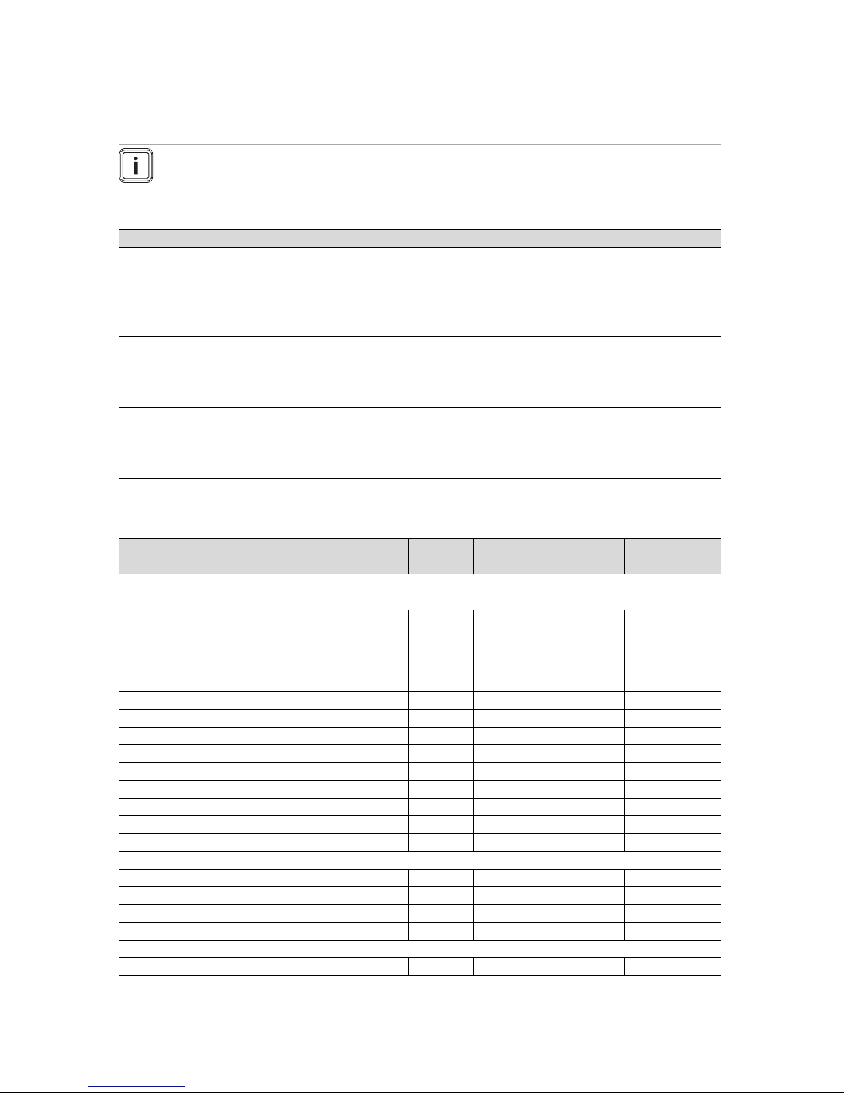
A Overview of the operating and display functions
Note
The functions and operating modes listed are not available for all system configurations.
A.1 Operating modes
Operating mode Setting Default setting
Operating mode
Heating off, Auto, Day, Set-back Auto
Cooling off, Auto, Day Auto
Ventilation Auto, Day, Set-back Auto
Domestic hot water off, Auto, Day Auto
Advanced functions
Manual cooling active –
1 day at home active –
1 day away from home active –
Ventilation boost active –
Party function active –
Cylinder boost active –
System OFF active active –
A.2 End user level
The description of the functions for ZONE1 also applies for all available zones.
Setting level Values Unit Increment, select Default setting
Min. Max.
Information → System status →
System ----
Fault status Current value No fault, Fault list
Green IQ Off, On On
Water pressure Current value bar
System status Current value Standby, Heat. mode, Cool-
ing, DHW
Burner Current value On, off
Collector temp. Current value ℃
Solar yield Current value kWh
Reset solar yield Yes, No No
Environmental yield Current value kWh
Reset env.yield Yes, No No
Curr. room air hum. Current value %
Current dew point Current value ℃
triVAI Current value
ZONE1 ----
Day temp. heating 5 30 ℃ 0.5 20
Day temp. cooling 15 30 ℃ 0.5 24
Set-back temp. heat. 5 30 ℃ 0.5 15
Room temperature Current value ℃
Ventilation ----
Air quality sensor 1 Current value ppm

Appendix
22 Operating instructions multiMATIC 0020255037_00
Setting level Values Unit Increment, select Default setting
Min. Max.
Air quality sensor 2 Current value ppm
Exhaust air humidity Current value %rel
Information → Consumption → Current month →
Heating ----
Electricity Total value for the
current month
kWh
Fuel Total value for the
current month
kWh
Hot water ----
Electricity Total value for the
current month
kWh
Fuel Total value for the
current month
kWh
Information → Consumption → Last month →
Heating ----
Electricity Total value for the last
month
kWh
Fuel Total value for the last
month
kWh
Hot water ----
Electricity Total value since start-upkWh
Fuel Total value since start-upkWh
Information → Consumption → History →
Heating ----
Electricity Total value since start-upkWh
Fuel Total value since start-upkWh
Hot water ----
Electricity Total value since start-upkWh
Fuel Total value since start-upkWh
Information → Solar yield →
Bar chart Previous year to cur-
rent year comparison
kWh/month
Information → Environmental yield →
Bar chart Previous year to cur-
rent year comparison
kWh/month
Information → Electrical consumption →
Bar chart Previous year to cur-
rent year comparison
kWh/month
Information → Fuel consumption →
Bar chart Previous year to cur-
rent year comparison
kWh/month

Appendix
0020255037_00 multiMATIC Operating instructions 23
Setting level Values Unit Increment, select Default setting
Min. Max.
Information → Heat recovery →
Bar chart Previous year to cur-
rent year comparison
kWh/month
Information → Contact details →
Installer Phone number Current values
Information → Serial number
Product number Permanent value
Desired temperatures → ZONE1 →
Day temp. heating 5 30 ℃ 0.5 20
Day temp. cooling 15 30 ℃ 0.5 24
Set-back temp. heat. 5 30 ℃ 0.5 15
Desired temperatures → Domestic hot water →
Domestic hot water 35 70 ℃ 1 60
Ventilation stage →
Max. vent. stage: Day Depending on the
ventilation unit
1 Depending on the
ventilation unit
Max. vent. stge: Night Depending on the
ventilation unit
1 Depending on the
ventilation unit
Time programmes → ZONE1 (Heating) →
Time programmes → ZONE1: Cooling →
Time programmes → Circulation →
Time programmes → Ventilation →
Individual days and blocks Monday, Tuesday, Wednes-
day, Thursday, Friday, Saturday, Sunday and Monday
- Friday, Saturday - Sunday,
Monday - Sunday
Mo - Fr: 06:0022:00
Sa: 07:30-23:30
Su: 07:30-22:00
Period 1: Start – End
Period 2: Start – End
Period 3: Start – End
00:00 24:00 h:min 00:10
Time programmes → Domestic hot water →
Individual days and blocks Monday, Tuesday, Wednes-
day, Thursday, Friday, Saturday, Sunday and Monday
- Friday, Saturday - Sunday,
Monday - Sunday
Mo to Fr: 05:3022:00
Sa: 07:00-23:30
Su: 07.00-22.00
Period 1: Start – End
Period 2: Start – End
Period 3: Start – End
00:00 24:00 h:min 00:10
Time programmes → High tariff →
Individual days and blocks Monday, Tuesday, Wednes-
day, Thursday, Friday, Saturday, Sunday and Monday
- Friday, Saturday - Sunday,
Monday - Sunday
Mo - Su: 11:0013:00

Appendix
24 Operating instructions multiMATIC 0020255037_00
Setting level Values Unit Increment, select Default setting
Min. Max.
Period 1: Start – End
Period 2: Start – End
Period 3: Start – End
00:00 24:00 h:min 00:10 Mo - Su: 11:00-
13:00
Days away from home scheduling →
Start 01.01.01 31.12.99 dd.mm.yy Day.Month.Year 01.01.14
End 01.01.01 31.12.99 dd.mm.yy Day.Month.Year 01.01.14
Temperature 5 30 ℃ 1 15
Days at home scheduling →
Start 01.01.01 31.12.99 dd.mm.yy Day.Month.Year 01.01.14
End 01.01.01 31.12.99 dd.mm.yy Day.Month.Year 01.01.14
Basic settings → Language →
Selectable language English
Basic settings → Date/time →
Date 01.01.01 31.12.99 dd.mm.yy Day.Month.Year 01.01.15
Time 00:00 23:59 h:min 00:10 08:00
Daylight saving time Manual, Auto Manual
Basic settings → Display →
Display contrast 1 15 1 9
Button lock off, On off
Preferred display Heating, Cooling, Vent. Heating
Basic settings → Costs →
Tariff for aux. heater 1 999 1 12
Low-tariff elec. rate 1 999 1 16
High-tariff elec. rate 1 999 1 20
Basic settings → Offset →
Room temperature -3.0 3.0 K 0.5 0.0
Outside temperature -3.0 3.0 K 0.5 0.0
Basic settings → Operating mode → ZONE1 →
Heating off, Auto, Day, Set-back Auto
Cooling off, Auto, Day Auto
1 day at home Active, Not active Not active
1 day away from home Active, Not active Not active
Ventilation boost Active, Not active Not active
Party function Active, Not active Not active
Basic settings → Enter zone name →
ZONE1 1 10 Let-
ter/number
A to Z, 0 to 9, space ZONE1
Basic settings → Ventilation →
Heat recovery Auto, Activate, off Auto

Appendix
0020255037_00 multiMATIC Operating instructions 25
Setting level Values Unit Increment, select Default setting
Min. Max.
Basic settings → Max. room air humidity →
Max. room air hum. 30 70 %rel 1 40
Basic settings → Default setting →
Time programmes Yes, No No
Everything Yes, No No
Installer level →
Enter code 000 999 1 000
B Troubleshooting
Symptom Possible cause Measure
Display remains dark Software error 1. Switch off the mains switch on all heat generators for approx.
1 minute and then switch them on again.
2. If the fault persists, inform the competent person.
No changes in the display when
the rotary knob is turned
Software error 1. Switch off the mains switch on all heat generators for approx.
1 minute and then switch them on again.
2. If the fault persists, inform the competent person.
No changes in the display
when the selection buttons are
pressed
Software error 1. Switch off the mains switch on all heat generators for approx.
1 minute and then switch them on again.
2. If the fault persists, inform the competent person.
Display view: Button lock act-
ive To unlock, press OK for
3 seconds, it is not possible to
change the settings or values
Button lock is active 1. If you would like to change any of the values, follow the in-
structions on the display.
2. Also read through the Button lock Activate (→ Page 15)
function.
Display view: Restricted opera-
tion/ comfort protection, insufficient heating up of the heating
and the domestic hot water
Heat pump does not work 1. Inform the competent person.
2. Select the setting for limp home mode until the competent
person arrives.
3. Read the "Temporarily setting limp home mode (→ Page 18)"
function for more details.
Display view: Fault F. Fault:
Heat generator 1, the specific
fault code (e.g. F.33) and the
specific heat generator appear
behind F. in the display
Heat generator faults 1. Press the Reset selection button.
– Heat generator fault clearance? appears in the display.
2. Press the OK selection button.
– Faults are cleared for the heat generator briefly ap-
pears in the display.
3. If the fault persists, inform the competent person.
C Maintenance messages
The maintenance message Service heat pump 1 is an example of a maintenance message that may appear for heat pumps
1 to 7.
The maintenance message Service heat generator 1 is an example of a maintenance message that may appear for heat
generators 1 to 7.
# Message Description Maintenance work Interval
1 Service heat
pump 1
The heat pump requires maintenance work.
Refer to the operating instructions of the relevant heat pump
for information on the maintenance work required
See the operating instructions
for the heat pump
2 Service heat
generator 1
The heat generator requires
maintenance work.
Refer to the operating instructions of the relevant heat generator for information on the maintenance work required
See the operating instructions
for the heat generator

Appendix
26 Operating instructions multiMATIC 0020255037_00
# Message Description Maintenance work Interval
3 Service ventila-
tion unit
The ventilation unit requires
maintenance work.
Refer to the operating instructions of the ventilation unit for
information on the maintenance
work required
See the operating instructions
for the ventilation unit
4 Low water pres-
sure
The water pressure in the heating system is too low.
Refer to the operating instructions for the relevant heat generator for information on filling
with water
See the operating instructions
for the heat generator
5 Service date
Next service on
The competent person has
entered a date on which maintenance is due for the heating
system.
Inform the competent person if
maintenance work is required
Date entered in the control

Index
0020255037_00 multiMATIC Operating instructions 27
Index
1
1 day at home ....................................................................17
1 day away from home......................................................17
A
Activating Button lock ........................................................15
Activating Heat recovery ....................................................16
Advanced functions ........................................................... 17
1 day at home............................................................... 17
1 day away from home ................................................ 17
Cylinder boost..............................................................18
Manual cooling...............................................................17
Party .............................................................................. 18
System OFF...................................................................18
Ventilation boost..........................................................18
Article number ....................................................................... 6
B
Basic display .........................................................................7
C
Caring for the product.......................................................... 19
CE label................................................................................. 6
Changing the display contrast, example ...............................9
Circulation ............................................................................. 6
Circulation time programme ................................................ 14
Competent person, contact details...................................... 12
Contact details...................................................................12
Contact details, competent person...................................... 12
Cooling .................................................................................. 5
Cylinder boost ................................................................... 18
D
Days at home scheduling .................................................... 14
Days away from home scheduling ......................................14
Desired temperature
Hot water generation ..................................................... 12
Setting............................................................................12
Zone...............................................................................12
Display level .......................................................................... 6
Display, solar statistics ........................................................ 12
Documents ............................................................................ 5
E
Electrical consumption..................................................... 12
Entering a zone name ......................................................... 16
Environmental yield .......................................................... 12
Example, changing the display contrast................................ 9
F
Fault message..................................................................... 18
Frost protection function........................................................ 6
Fuel consumption ................................................................12
H
Heat recovery yield.............................................................. 12
Heating ..................................................................................5
Hot water generation .......................................................6, 12
Hybrid manager..................................................................... 6
Hybrid manager heating installation......................................6
I
Information in the basic display ............................................. 7
Installer level .......................................................................16
Intended use..........................................................................3
L
Language selection ............................................................. 14
M
Main function .........................................................................5
Maintenance message ........................................................ 18
Manual cooling .................................................................... 17
N
Nomenclature ........................................................................5
O
Operating concept .................................................................8
Operating level ...................................................................... 6
Operating mode...................................................................16
Operating mode in the basic display ..................................... 7
Outside temperature, setting the offset ............................... 15
P
Party ....................................................................................18
Preventing a malfunction....................................................... 6
R
Reading the article number ............................................. 6, 12
Reading the electrical consumption ....................................12
Reading the environment yield............................................ 12
Reading the fuel consumption............................................. 12
Reading the heat recovery yield.......................................... 12
Reading the serial number .............................................. 6, 12
Reading the solar statistics .................................................12
Reading the system status .................................................. 10
Restoring the language ....................................................... 14
Room temperature, setting the offset .................................. 15
S
Selection level ....................................................................... 7
Serial number ........................................................................6
Set values after a voltage loss ............................................ 13
Setting costs........................................................................ 15
Setting daylight saving time................................................. 15
Setting level........................................................................... 7
Setting the air humidity........................................................16
Setting the Cooling operating mode................................... 16
Setting the Cooling time programme.................................. 14
Setting the date ................................................................... 15
Setting the date, time ..........................................................14
Setting the display ............................................................... 15
Setting the display contrast ................................................. 15
Setting the Heating operating mode ................................... 16
Setting the Heating time programme.................................. 13
Setting the High tariff time programme .............................. 14
Setting the high-tariff electricity rate .................................... 15
Setting the hot water generation time programme .............. 14
Setting the low-tariff electricity rate .....................................15
Setting the offset outside temperature ................................15
Setting the offset room temperature.................................... 15
Setting the operating mode for hot water generation .......... 17
Setting the preferred display ...............................................15
Setting the room air humidity............................................... 16
Setting the standard time ....................................................15
Setting the tariff for the auxiliary boiler ................................ 15
Setting the time ...................................................................15
Setting the ventilation level.................................................. 12
Setting the Ventilation operating mode.............................. 17
Setting the Ventilation time programme............................. 14
Setting time periods for days and blocks............................. 13
Soft key function.................................................................... 7
System OFF ........................................................................ 18
System status...................................................................... 10

Index
28 Operating instructions multiMATIC 0020255037_00
T
Time period, deviating times in the block ............................13
Time programme
quick setting................................................................... 13
Setting............................................................................13
Time programme after switching off the voltage ................. 13
V
Ventilation..............................................................................5
Ventilation boost ............................................................... 18
Ventilation level ................................................................... 12
Z
Zone ................................................................................6, 12
Zone in the basic display.......................................................7


0020255037_00 30.06.2017
Supplier
VAILLANT GROUP FRANCE
"Le Technipole" 8, Avenue Pablo Picasso
F-94132 Fontenay-sous-Bois Cedex
Téléphone 01 49741111 Fax 01 48768932
Assistance technique 08 26 270303 (0,15 EUR TTC/min) Ligne Particuliers 09 74757475 (0,022 EUR
TTC/min + 0,09 EUR TTC de mise en relation)
www.vaillant.fr
N.V. Vaillant S.A.
Golden Hopestraat 15 B-1620 Drogenbos
Tel. 2 3349300 Fax 2 3349319
Kundendienst / Service après-vente / Klantendienst 2 3349352
info@vaillant.be www.vaillant.be
Vaillant Sàrl
Rte du Bugnon 43 CH-1752 Villars-sur-Glâne
Tél. 026 40972‑10 Fax 026 40972‑14
Service après-vente tél. 026 40972‑17 Service après-vente fax 026 40972‑19
romandie@vaillant.ch www.vaillant.ch
N.V. Vaillant S.A.
Golden Hopestraat 15 B-1620 Drogenbos
Tel. 2 3349300 Fax 2 3349319
Kundendienst / Service après-vente / Klantendienst 2 3349352
info@vaillant.be www.vaillant.be
© These instructions, or parts thereof, are protected by copyright and may be reproduced or distributed only with
the manufacturer's written consent.
We reserve the right to make technical changes.
0020255037_00
 Loading...