

Page 1
Installation and maintenance instructions
For the competent person
Installation and maintenance instructions
Publisher/manufacturer
Vaillant GmbH
Berghauser Str. 40 D-42859 Remscheid
Tel. +49 21 91 18‑0 Fax +49 21 91 18‑28 10
info@vaillant.de www.vaillant.de
HOME
COMBI
GB, IE
Page 2

Contents
Contents
1 Safety .................................................................... 4
1.1 Action-related warnings......................................... 4
1.2 Risk caused by inadequate qualifications.............. 4
1.3 Intended use ......................................................... 4
1.4 General safety information .................................... 4
1.5 Regulations (directives, laws, standards) .............. 6
2 Notes on the documentation .............................. 7
2.1 Observing other applicable documents ................. 7
2.2 Storing documents................................................. 7
2.3 Applicability of the instructions .............................. 7
3 Product description............................................. 7
3.1 Serial number ........................................................ 7
3.2 Information on the identification plate.................... 7
3.3 Functional elements: Combination unit ................. 8
3.4 CE label ................................................................. 8
4 Installation............................................................ 8
4.1 Transporting the unit.............................................. 8
4.2 Unpacking the product........................................... 8
4.3 Checking the scope of delivery.............................. 8
4.4 Dimensions............................................................ 9
4.5 Minimum clearances.............................................. 9
4.6 Clearance from combustible components ............. 9
4.7 Using the installation template............................... 9
4.8 Wall-mounting the product..................................... 9
4.9 Removing/installing the front casing.................... 10
4.10 Removing/installing the side section ................... 10
5 Installation.......................................................... 10
5.1 Checking the gas meter....................................... 11
5.2 Gas and water connections ................................. 11
5.3 Connecting the drain line for the expansion
relief valve............................................................ 11
5.4 Connecting the condensate drain pipework ........ 12
5.5 Connecting the drain cock ................................... 12
5.6 Flue gas installation ............................................. 12
5.7 Electrical installation ............................................ 14
6 Operation............................................................ 15
6.1 Using diagnostics codes ...................................... 15
6.2 Displaying the status codes ................................. 16
6.3 Using check programmes .................................... 16
7 Start-up ............................................................... 16
7.1 Carrying out the initial start-up............................. 16
7.2 Checking the factory setting ................................ 16
7.3 Checking and treating the heating water/filling
and supplementary water .................................... 17
7.4 Avoiding danger arising from insufficient water
pressure............................................................... 18
7.5 Switching on the product ..................................... 18
7.6 Filling and purging the heating installation .......... 18
7.7 Filling the condensate siphon .............................. 18
7.8 Filling the hot water circuit ................................... 18
7.9 Checking and adjusting the gas settings............. 19
7.10 Checking function and leak-tightness.................. 20
8 Adapting the unit to the heating
installation.......................................................... 20
8.1 Burner anti-cycling time ....................................... 20
8.2 Setting the pump output....................................... 21
8.3 Setting the bypass ............................................... 21
9 Adjusting the hot water temperature............... 22
9.1 Setting the hot water temperature ....................... 22
10 Handing the product over to the operator ...... 22
11 Inspection and maintenance ............................ 22
11.1 Observing inspection and maintenance
intervals ............................................................... 22
11.2 Procuring spare parts .......................................... 22
11.3 Checking the CO₂ content ................................... 22
11.4 Setting the CO₂ content ....................................... 23
11.5 Removing the gas-air mixture unit....................... 23
11.6 Cleaning the heat exchanger............................... 24
11.7 Checking the burner ............................................ 24
11.8 Checking the ignition electrode ........................... 24
11.9 Cleaning the condensate tray .............................. 24
11.10 Cleaning the condensate siphon ......................... 25
11.11 Cleaning the filter in the cold water inlet .............. 25
11.12 Cleaning the heating filter .................................... 25
11.13 Installing the gas-air mixture unit......................... 26
11.14 Draining the product ............................................ 26
11.15 Checking the pre-charge pressure of the
expansion vessel ................................................. 26
11.16 Completing inspection and maintenance work .... 26
12 Troubleshooting ................................................ 26
12.1 Rectifying faults ................................................... 26
12.2 Calling up the fault memory................................. 26
12.3 Deleting the fault memory.................................... 26
12.4 Resetting parameters to factory settings ............. 26
12.5 Preparing the repair work .................................... 26
12.6 Replacing defective components......................... 26
12.7 Completing repair work........................................ 29
13 Decommissioning the product ......................... 29
14 Customer service............................................... 29
Appendix ............................................................................ 30
A Check programmes – Overview ....................... 30
B Overview of diagnostics codes........................ 30
C Status codes – Overview .................................. 34
D Overview of fault codes .................................... 35
E Connection diagram: Combination unit .......... 38
F Connection diagram: Combination unit (35
kW) ...................................................................... 39
G Inspection and maintenance work –
Overview............................................................. 40
H Opening in the air/flue pipe .............................. 41
H.1 Positioning of the opening of a fan-supported
flue gas pipe ........................................................ 41
H.2 Text from BS 5440-1 on fan-supported flue
gas pipes ............................................................. 42
H.3 Opening of the flue pipe below eaves and
balconies.............................................................. 42
I Commissioning Checklist................................. 43
2 Installation and maintenance instructions HOME 0020224355_00
Page 3

J Combustion chart.............................................. 46
K Lengths of the air/flue pipe............................... 47
L Technical data.................................................... 47
Index ................................................................................... 50
Contents
0020224355_00 HOME Installation and maintenance instructions 3
Page 4

1 Safety
1 Safety
1.1 Action-related warnings
Classification of action-related warnings
The action-related warnings are classified in
accordance with the severity of the possible
danger using the following warning signs and
signal words:
Warning symbols and signal words
Danger!
Imminent danger to life or risk of
severe personal injury
Danger!
Risk of death from electric shock
Warning.
Risk of minor personal injury
Caution.
Risk of material or environmental
damage
– observance of accompanying operating,
installation and servicing instructions for
the product and any other system components
– installing and fitting the product in accord-
ance with the product and system approval
– compliance with all inspection and main-
tenance conditions listed in the instructions.
Intended use also covers installation in accordance with the IP class.
Any other use that is not specified in these
instructions, or use beyond that specified in
this document shall be considered improper
use. Any direct commercial or industrial use
is also deemed to be improper.
Caution.
Improper use of any kind is prohibited.
1.4 General safety information
1.2 Risk caused by inadequate qualifications
Assembly and disassembly, installation, startup, maintenance, repairs and decommissioning must only be carried out by a competent person who is sufficiently qualified to observe all of the instructions that come with the
product, to proceed in accordance with the
current state of the art, and to comply with
all applicable directives, standards, laws and
other regulations.
1.3 Intended use
There is a risk of injury or death to the user or
others, or of damage to the product and other
property in the event of improper use or use
for which it is not intended.
The product is intended as a heat generator
for closed central heating installations and for
hot water generation.
The products referred to in these instructions
must only be installed and operated in conjunction with the flue pipe accessories listed
in other applicable documents.
Exceptions: For C63 and B23P installation
types, follow the specifications in these instructions.
Intended use includes the following:
1.4.1 Risk of death from escaping gas
What to do if you smell gas in the building:
▶ Avoid rooms that smell of gas.
▶ If possible, open doors and windows fully
and ensure adequate ventilation.
▶ Do not use naked flames (e.g. lighters,
matches).
▶ Do not smoke.
▶ Do not use any electrical switches, mains
plugs, doorbells, telephones or other communication systems in the building.
▶ If it is safe to do so, close the emergency
control valve or the main isolator.
▶ If possible, close the gas isolator cock on
the product.
▶ Warn other occupants in the building by
yelling or banging on doors or walls.
▶ Leave the building immediately and ensure
that others do not enter the building.
▶ Notify the gas supply company or National
Grid Transco +44 (0) 800 111999 by telephone from outside of the building.
1.4.2 Risk of death from escaping flue gas
If you operate the product with an empty condensate siphon, flue gas may escape into the
room air.
4 Installation and maintenance instructions HOME 0020224355_00
Page 5

Safety 1
▶ In order to operate the product, ensure that
the condensate siphon is always full.
1.4.3 Risk of death due to blocked or leaking flue gas routes
Installation errors, damage, tampering, unauthorised installation sites or similar can cause
flue gas to escape and result in a risk of poisoning.
What to do if you smell flue gas in the property:
▶ Open all accessible doors and windows
fully to provide ventilation.
▶ Switch off the product.
▶ Check the flue gas routes in the product
and the flue gas diversions.
1.4.4 Risk of death due to explosive and flammable materials
▶ Do not use or store explosive or flammable
materials (e.g. petrol, paper, paint) in the
installation room of the product.
1.4.5 Risk of death from electric shock
There is a risk of death from electric shock if
you touch live components.
Before commencing work on the product:
▶ Unplug the mains plug.
▶ Or disconnect the product from the power
supply by switching off all power supplies
(electrical partition with a contact opening
of at least 3 mm, e.g. fuse or line protection switch).
▶ Secure against being switched back on
again.
▶ Wait for at least 3 minutes until the con-
densers have discharged.
1.4.6 Risk of death due to lack of safety devices
The schematic drawings included in this document do not show all safety devices required for correct installation.
▶ Install the necessary safety devices in the
system.
▶ Observe the applicable national and inter-
national laws, standards and guidelines.
1.4.7 Risk of poisoning and burns caused by escaping hot flue gases
▶ Only operate the product if the air/flue pipe
has been completely installed.
▶ With the exception of short periods for
testing purposes, only operate the product
when the front casing is installed and
closed.
1.4.8 Risk of being burned or scalded by hot components
▶ Only carry out work on these components
once they have cooled down.
1.4.9 Risk of injury during transport due to a high product weight.
▶ Make sure that the product is transported
by at least two people.
1.4.10 Risk of corrosion damage due to
unsuitable combustion and room
air
Sprays, solvents, chlorinated cleaning
agents, paint, adhesives, ammonia compounds, dust or similar substances may lead
to corrosion on the product and in the air/flue
pipe.
▶ Ensure that the supply of combustion air is
always free of fluorine, chlorine, sulphur,
dust, etc.
▶ Ensure that no chemical substances are
stored at the installation site.
▶ Ensure that the combustion air is not
routed through chimneys which have
previously been used with floor-standing
oil-fired boilers, or with other boilers,
which could cause soot to build up in the
chimney.
▶ If you are installing the product in
hairdressing salons, painter's or joiner's
workshops, cleaning businesses or similar
locations, choose a separate installation
room in which a combustion air supply is
ensured that is technically free of chemical
substances.
1.4.11 Risk of material damage caused by
frost
▶ Do not install the product in rooms prone
to frost.
0020224355_00 HOME Installation and maintenance instructions 5
Page 6

1 Safety
1.4.12 Risk of material damage caused by using an unsuitable tool
▶ Use the correct tool to tighten or loosen
screw connections.
1.5 Regulations (directives, laws,
standards)
▶ Observe the national regulations, stand-
ards, guidelines and laws.
6 Installation and maintenance instructions HOME 0020224355_00
Page 7
Notes on the documentation 2
2
1
2 Notes on the documentation
2.1 Observing other applicable documents
▶ You must observe all the operating and installation in-
structions included with the system components.
2.2 Storing documents
▶ Pass these instructions and all other applicable docu-
ments on to the system operator.
2.3 Applicability of the instructions
These instructions apply only to:
Product article number
Article number Gas Council Num-
ber
HOME COMBI 25
-A (H-GB)
HOME COMBI 30
-A (H-GB)
HOME COMBI 35
-A (H-GB)
These products are only designed for natural gas systems.
0010019930 47-044-62
0010019931 47-044-63
0010019932 47-044-64
3 Product description
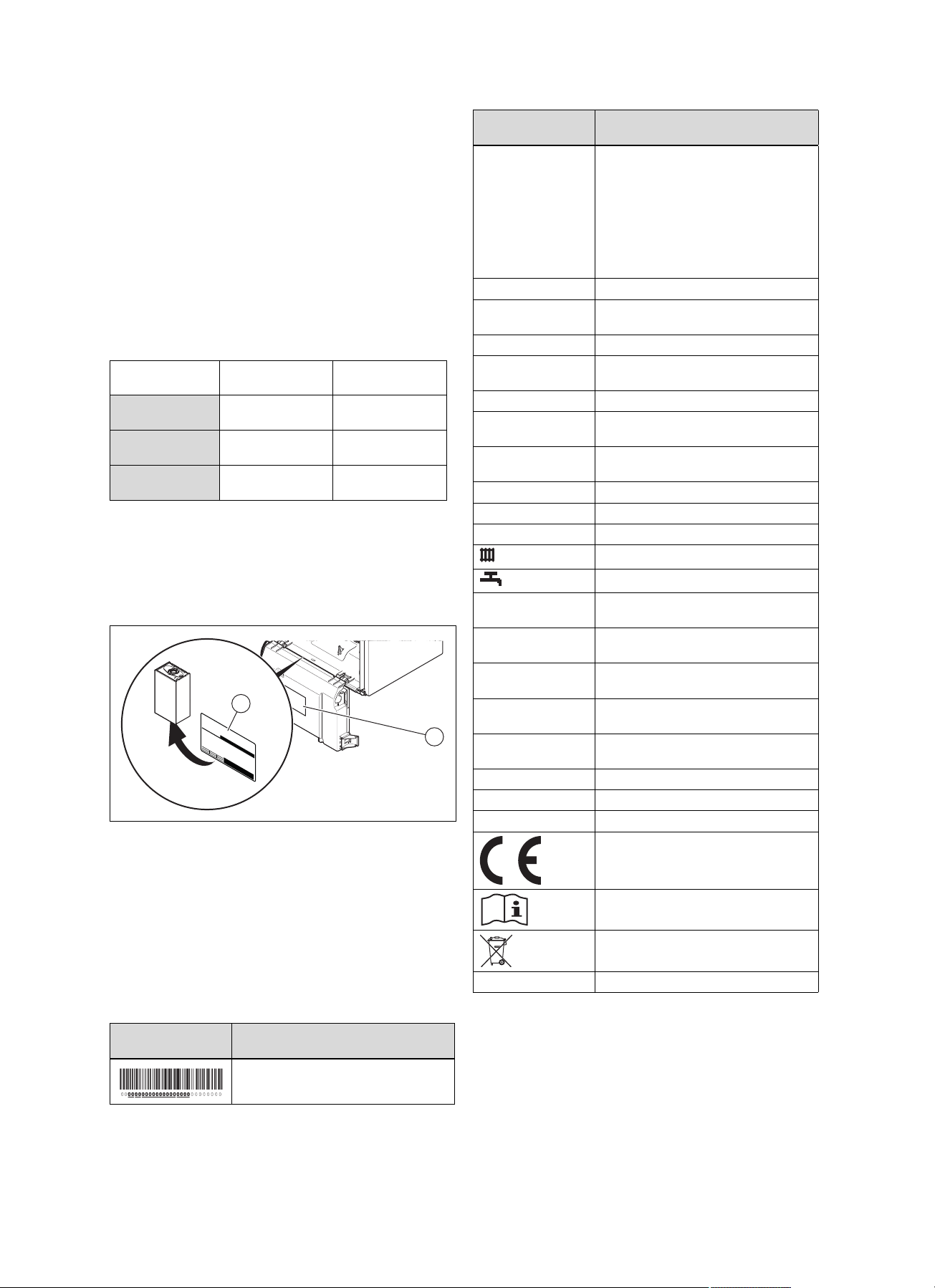
3.1 Serial number
The serial number can be found on the identification plate (1)
(→ Page 7).
Stickers showing the serial number are on the back of the
electronics box (2).
3.2 Information on the identification plate
The identification plate is mounted on the underside of the
product in the factory.
The identification plate keeps record of the country in which
the product is to be installed.
Information on the
identification plate
Serial number For quality control purposes; 3rd and 4th
HOME COMBI Product description
XX, Gxx – xx mbar
(x kPa)
Cat. Approved gas category
Condensing technology
Type: Xx3(x) Permissible flue gas connections
PMS Maximum water pressure in heating
PMW Maximum water pressure in hot water
V/Hz Electric connection
W Max. electrical power consumption
IP Level of protection
Pn Nominal heat output range in heating
Pnc Nominal heat output range in heating
P Nominal heat output range in hot water
Qn Nominal heating load range in heating
Qnw Nominal heating load range in hot water
T
max.
NOx NOx class for the product
Code (DSN) Specific product code
GC no. Gas council number
Meaning
digits = year of production
For quality control purposes; 5th and 6th
digits = week of production
For identification purposes; 7th to 16th
digits = product article number
For quality control purposes; 17th to 20th
digits = place of manufacture
Gas group and gas connection pressure
as set at the factory
Efficiency class of the boiler in accordance with EC Directive 92/42/EEC
mode
handling mode
Heating mode
Hot water generation
mode
mode (condensing technology)
handling mode
mode
handling mode
Max. flow temperature
→ "CE label" section
Read the instructions.
→ "Recycling and disposal" section
Information on the
identification plate
0020224355_00 HOME Installation and maintenance instructions 7
Meaning
Barcode with serial number
Page 8
4 Installation
14
12
11
10
8
9
7
5
6
4
3
2
1
16
15
18 17
13
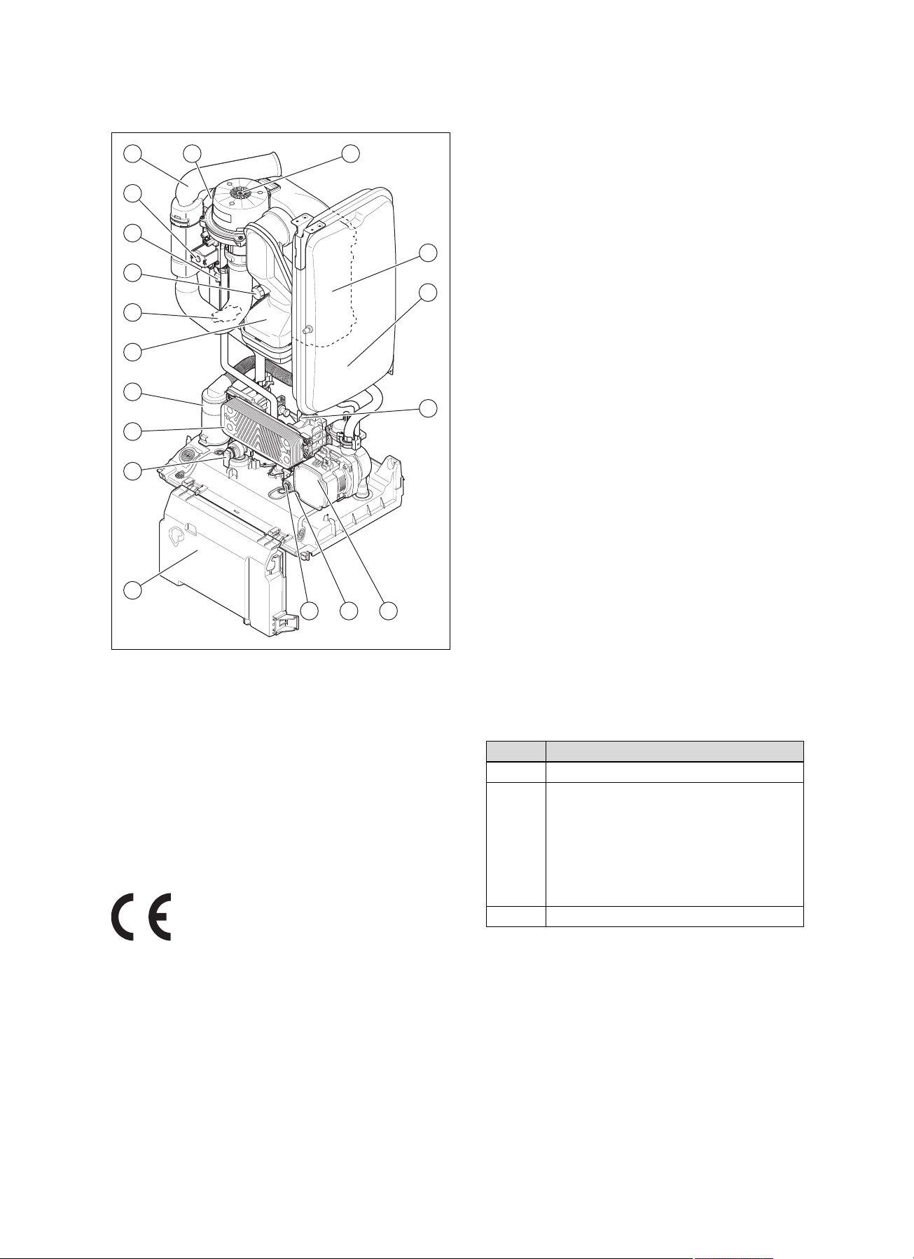
3.3 Functional elements: Combination unit
4 Installation
4.1 Transporting the unit
Important: With regard to the regulations of 1992 concern-
ing the manual handling of loads, the unit exceeds the
weight that can be lifted by a single person.
4.1.1 General
▶ Hold the load as close as possible to your body. Avoid
rotational movements. Instead, reposition your feet.
▶ If the unit is being lifted by two persons, ensure your
movements are coordinated during lifting.
▶ Avoid bending your upper body – do not lean forwards or
to the side.
▶ Wear suitable non-slip protective gloves in order to pro-
tect your hands against sharp edges. Ensure that you are
carrying the load securely.
▶ If required, get somebody to assist you in this.
4.1.2 Unloading the box from the delivery van
▶ It is recommended that two people lift the unit together.
▶ Lift the box using the straps provided.
▶ Use safe lifting techniques – keep your back straight and
bend your legs at the knee.
▶ Hold the load as close as possible to your body.
▶ If the unit is being lifted by two persons, ensure your
movements are coordinated during lifting.
▶ If required, get somebody to assist you in this.
4.2 Unpacking the product
1. Remove the product from its box.
1 Electronics box
2 Heating circuit expan-
sion relief valve
3 Plate heat exchanger
4 Condensate siphon
5 Flue pipe
6 Pressure sensor
7 Flue gas analysis point
8 Ignition transformer
9 Gas valve
3.4 CE label
The CE label shows that the products comply with the basic
requirements of the applicable directives as stated on the
identification plate.
The declaration of conformity can be viewed at the manufacturer's site.
10 Air intake pipe
11 Ignition electrode
12 Fan
13 Primary heat exchanger
14 Heating expansion
vessel
15 Volume flow sensor
16 Heating pump
17 Bypass
18 3-way valve
2. Remove the protective film from all of the product's
components.
4.3 Checking the scope of delivery
▶ Check that the scope of delivery is complete.
Quantity Description
1
1
1 Enclosed documentation
Heat generator
Bag with accessories
– Bag with seals
– Condensate drain hose
– Drain spigot of the expansion relief valve
– Installation template
– Hanging bracket
– Bag containing the hydraulic connections
8 Installation and maintenance instructions HOME 0020224355_00
Page 9
Installation 4
A
C
B
D
A A
D
BC
A
B
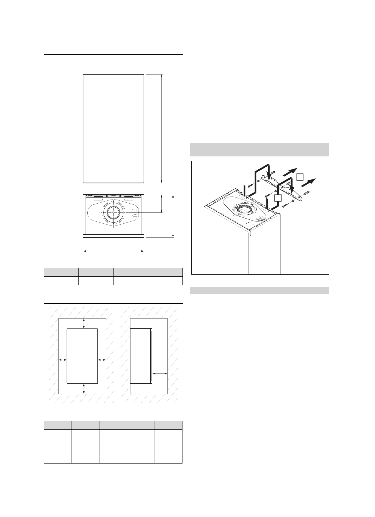
4.4 Dimensions
4.6 Clearance from combustible components
It is not necessary to maintain a clearance between the
product and components made of combustible materials.
4.7 Using the installation template
▶ Use the installation template to ascertain the locations at
which you need to drill holes and make breakthroughs.
4.8 Wall-mounting the product
1. Check whether the wall has sufficient load-bearing capacity to bear the operational weight of the product.
2. Wall-mount the product as described using the adapted
fixing material provided on-site.
Conditions: The load-bearing capacity of the wall is sufficient, The fixing
material may be used for the wall
Dimensions
A B C D
740 mm 130 mm 300 mm 418 mm
4.5 Minimum clearances
Minimum clearances
A B C D D
≥ 0 mm ≥ 300 mm ≥ 300 mm ≥ 600 mm ≥ 5 mm
▶ Wall-mount the product as described.
Conditions: The load-bearing capacity of the wall is not sufficient
▶ Ensure that wall-mounting apparatus on-site has a suf-
ficient load-bearing capacity. Use individual stands or
primary walling, for example.
▶ Do not wall-mount the product if you cannot provide
wall-mounting apparatus with a sufficient load-bearing
capacity.
Note
Cabinettype casing
0020224355_00 HOME Installation and maintenance instructions 9
Page 10
5 Installation
B
C
A
1
1
2x
1
A
B
C
D
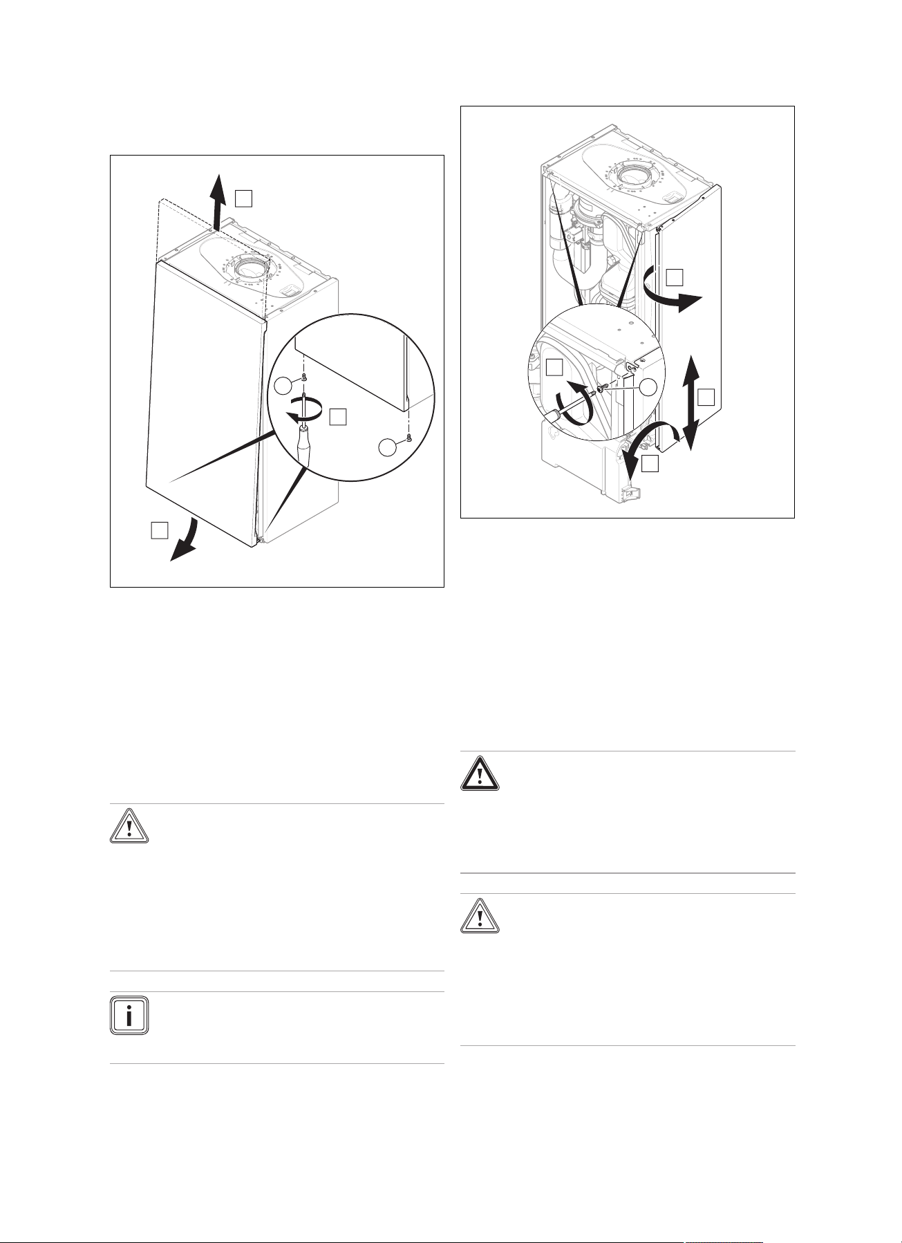
4.9 Removing/installing the front casing
4.9.1 Removing the front casing
1. Undo the two screws (1).
2. Gently press the front casing backwards in the centre
so that the latching lug is released.
3. Pull the front casing forwards at the bottom edge.
4. Lift the front casing upwards from the bracket.
4.9.2 Fitting the front panel
▶ Refit the components in the reverse order.
4.10 Removing/installing the side section
4.10.1 Removing the side section
Caution.
Risk of material damage caused by mech-
anical deformation.
Removing both side sections may cause
mechanical distortion in the product, which
may cause damage to the piping, for example, and potentially result in leaks.
▶ Always remove only one side section –
never both side sections at the same time.
Note
If there is sufficient lateral clearance (at least 50
mm), you can remove the side section to facilitate
maintenance or repair work.
1. Tilt the electronics box forward.
2. Hold on to the side section so that it cannot fall and
unscrew both screws (1), one from the top and one
from the bottom.
3. Tilt the side section to the outside and move it downwards and out.
4.10.2 Installing the side section
▶ Refit the components in the reverse order.
5 Installation
Danger!
Risk of explosion or scalding caused by
incorrect installation.
Stresses in the supply line can cause leaks.
▶ Make sure there is no voltage in the sup-
ply lines when they are installed.
Caution.
Risk of damage caused by contaminated
lines.
Foreign bodies, such as welding remnants,
sealing residue or dirt in the water pipes, may
cause damage to the boiler.
▶ Flush the heating installation thoroughly
prior to installation.
10 Installation and maintenance instructions HOME 0020224355_00
Page 11
5.1 Checking the gas meter
1
2
3
4
5
1
▶ Make sure that the existing gas meter is capable of
passing the rate of gas supply required.
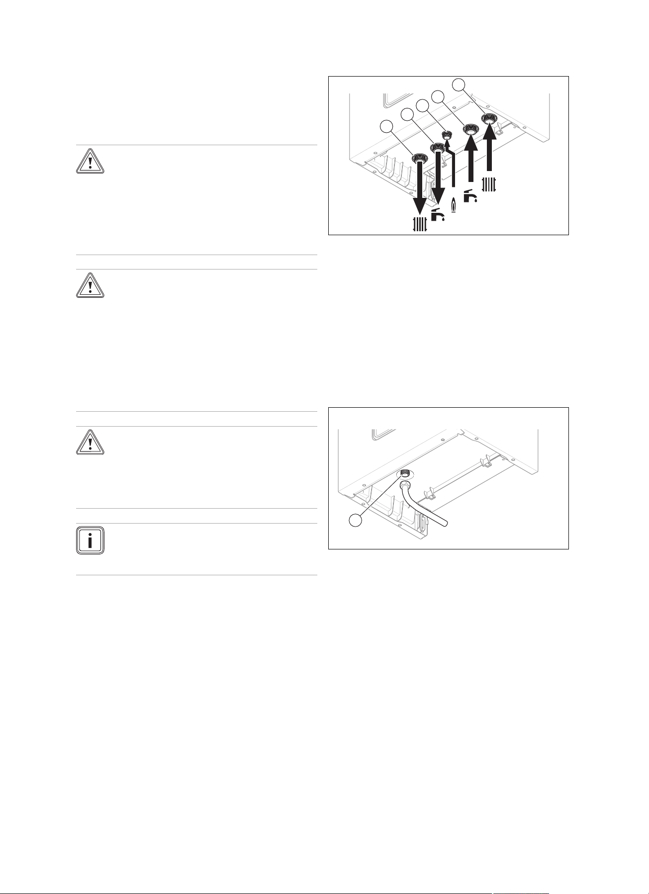
5.2 Gas and water connections
Caution.
Risk of damage caused by incorrect gas
connection installation.
Excess test pressure or operating pressure
may cause damage to the gas valve.
▶ Check the leak-tightness of the gas valve
using a maximum pressure of 1.1 kPa
(110 mbar).
Caution.
Risk of damage caused by corrosion.
If non-diffusion-tight plastic pipes are used in
the heating installation, this may cause air to
enter the heating water and corrosion of the
heat generation circuit and the boiler.
▶ If using non-diffusion-tight plastic pipes
in the heating installation, separate the
system by installing an external heat exchanger between the boiler and the heating installation.
Installation 5
1 Heating flow connec-
tion, G3/4
2 Hot water connection,
G3/4
3 Gas connection, G1/2
1. Connect the water and gas connections in accordance
with the applicable standards.
2. Purge the gas line before start-up.
3. Check whether the connections (→ Page 20) are leaktight.
5.3 Connecting the drain line for the expansion
relief valve
4 Connection for the cold
water supply line, G3/4
5 Heating return connec-
tion, G3/4
Caution.
Risk of material damage due to heat trans-
fer during soldering.
▶ Do not solder the connection pieces if
the connection pieces are screwed to the
service valves.
Note
We recommend that you provide the water pipes
to the boiler outlet and to the system with thermal
insulation.
Preliminary work
1. Check that the system volume and the volumetric capacity of the expansion vessel are the same.
▽ If the volume of the expansion vessel is insufficient
for the system.
▶ Install an additional expansion vessel in the
heating return, as close to the product as possible.
▶ Install a non-return flap at the product's outlet
(heating flow).
2. Ensure that the system has the following components:
– A stop cock in the cold water supply
– A stop cock in the gas line
– A filling and draining device in the heating installa-
tion
▶ Ensure that the pipeline is visible.
▶ The pipe must have a continuous fall and be routed to a
position so that any discharge of water, possibly boiling,
or steam cannot create any danger to persons, damage
to property or external electrical components and wiring.
◁ The components must be set up in such a way that
you can see the water flowing out.
0020224355_00 HOME Installation and maintenance instructions 11
Page 12
5 Installation
1
2
3
2
1
A
B
C
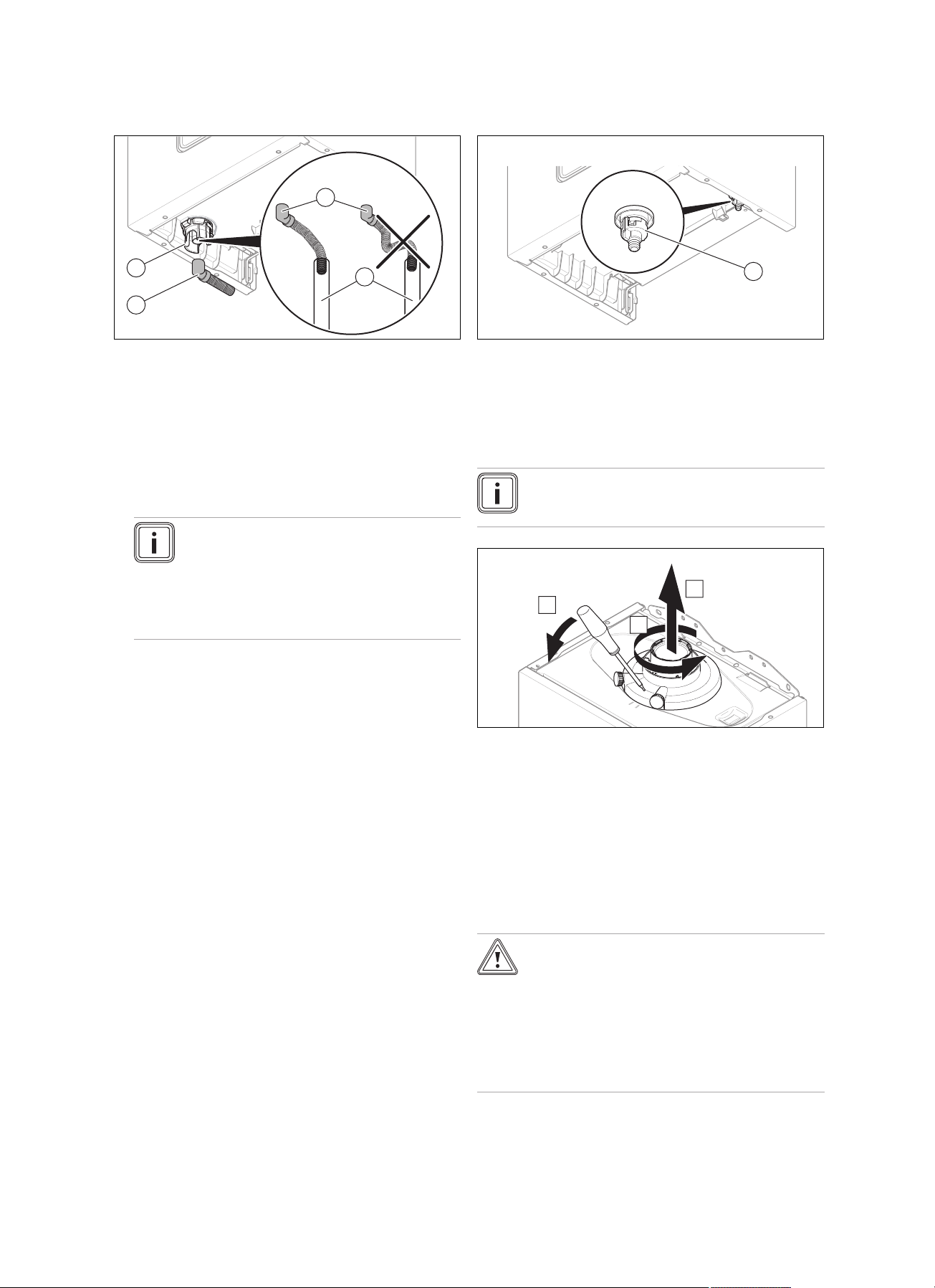
5.4 Connecting the condensate drain pipework
▶ Follow the instructions listed here and observe any legal
directives and local regulations on condensate discharge.
▶ Use PVC or another material that is suitable for draining
the non-neutralised condensate.
▶ If you cannot guarantee that the materials from which
the drain lines are made are suitable, install a system for
neutralising the condensate.
▶ Ensure that the connection between the condensate
drain pipework and the drain hose is not air-tight.
Note
The condensate drain pipework must have a
continuous fall (45 mm per metre) and should
whenever possible terminate at a suitable
drain point within the heated envelope of the
building that will remain frost free under long
periods of low external temperatures.
5.5 Connecting the drain cock
▶ Connect a hose to the drain cock (1) and guide the free
end of the hose to a suitable outflow location.
5.6 Flue gas installation
5.6.1 Replacing the connection piece for the air/flue pipe
Note
As standard, the product is equipped with a connection piece with a diameter of 60/100 mm.
▶ Connect the condensate siphon (1). Use the supplied
drain hose (2) for this.
▶ Connect condensate drain pipework (21.5 mm, not in-
cluded in the scope of delivery) (3) to the drain hose (2).
▶ During installation remove all burs from inside of cut pipe
work and avoid excessive adhesive which may trap small
pockets of water close to the pipe wall which can freeze
and build into a larger ice plug.
▶ As with other pipe work insulate the condensate dis-
charge pipe to minimise any risk of freezing and beware
when crossing cavities that the fall is maintained and the
pipe sleeved.
You can find further information in BS 6789: "Specification
for installing and maintaining gas-fired boilers with a nominal
heat loading less than 70 kW".
1. Insert a screwdriver into the slot between the measuring
stub pipes.
2. Push in the screwdriver carefully (A).
3. Turn the connector anticlockwise (B) as far as it will go
and then remove it by pulling it upwards (C).
4. Insert a new connector. In doing so, pay attention to the
latching lugs.
5. Turn the connection piece clockwise so that it clicks into
position.
5.6.2 Installing the air/flue pipe
Caution.
Risk of poisoning due to escaping flue
gas.
Mineral-oil-based greases can damage the
seals.
▶ Instead of grease, use only water or com-
mercially available soft soap to aid installation.
12 Installation and maintenance instructions HOME 0020224355_00
Page 13
50 mm/1m
5 %
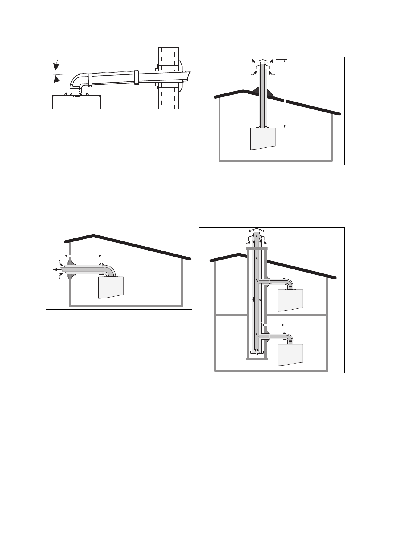
1. Ensure that there is a minimum downward gradient
L
L
L
of 5% between the elbow and the terminal on the
air/flue pipe so that the condensate can flow back to the
product.
2. Install the flue gas pipe in accordance with the installation instructions that are included in the scope of delivery for the air/flue pipe.
3. You can find out which air/flue pipes may be used by
consulting the enclosed air/flue pipe installation manual.
4. Install the flue gas pipe in accordance with the installation instructions that are included in the scope of delivery for the air/flue pipe.
5.6.3 Air/flue gas system
5.6.3.1 Horizontal air/flue gas system
Installation 5
5.6.3.2 Vertical air/flue gas system
The openings in an attachment for separate lines must lead
to a 50 cm-sided square.
For each additional 90° elbow (or two 45° elbows) that is
required, the length (L) must be reduced by 1 m.
Length of the C33 type flue pipe (→ Page 47)
5.6.3.3 Air/flue gas system for header lines
The openings in an attachment for separate lines must lead
to a 50 cm-sided square.
For each additional 90° elbow (or two 45° elbows) that is
required, the length (L) must be reduced by 1 m.
Length of the C13 type flue pipe (→ Page 47)
The connections with the line are established using the accessory specially developed by the product manufacturer.
A boiler that is connected to a type C43 system must only be
connected to natural draught chimneys.
The condensate from header line systems must not drain
into the boiler.
For each additional 90° elbow (or two 45° elbows) that is
required, the length (L) must be reduced by 1 m.
Length of the C43 type flue pipe (→ Page 47)
0020224355_00 HOME Installation and maintenance instructions 13
Page 14
5 Installation
B
B
A
230V
24V / eBus
30 mm max.
1
5.7 Electrical installation
Danger!
Risk of death from electric shock!
The mains connection terminals L and N remain live even if the product is switched off:
▶ Switch off the power supply.
▶ Secure the power supply against being
switched on again.
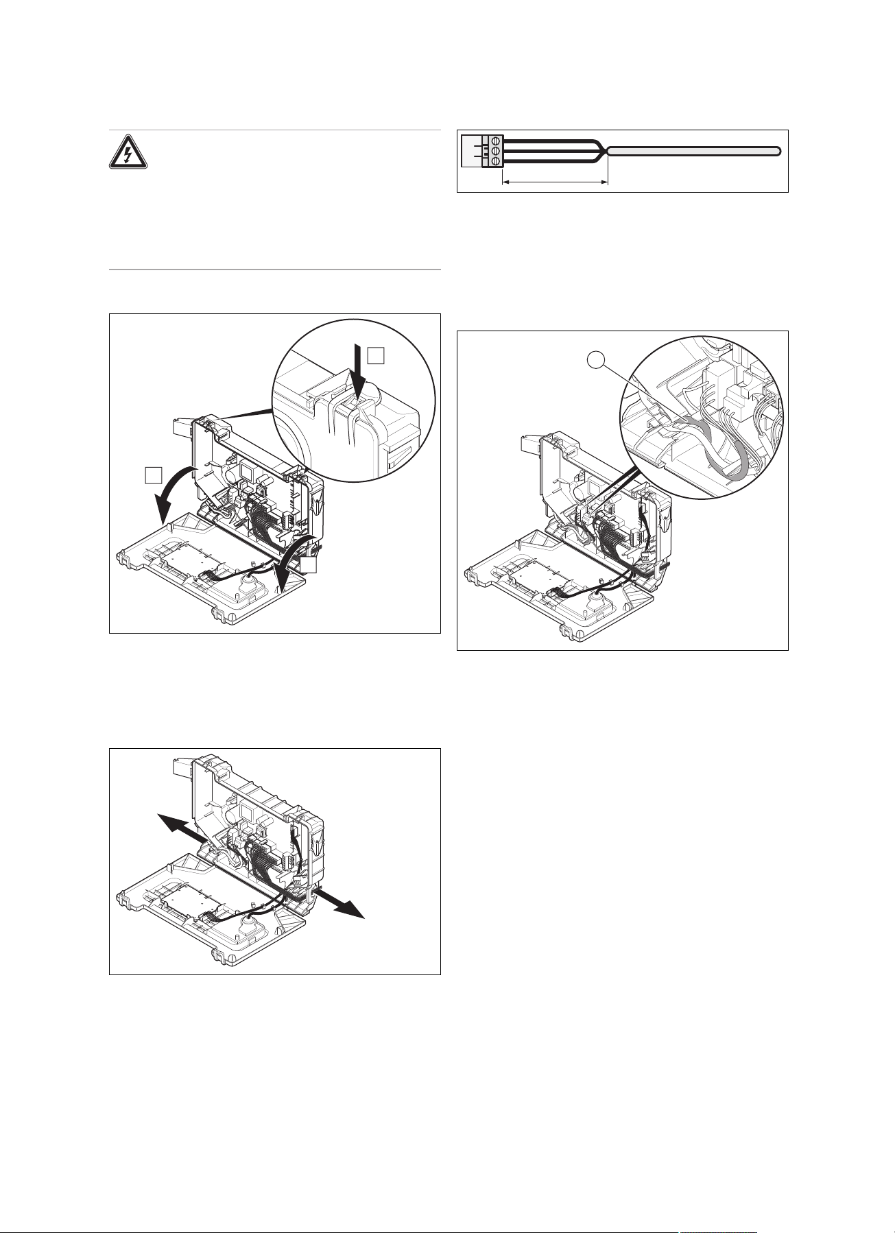
5.7.1 Opening and closing the electronics box
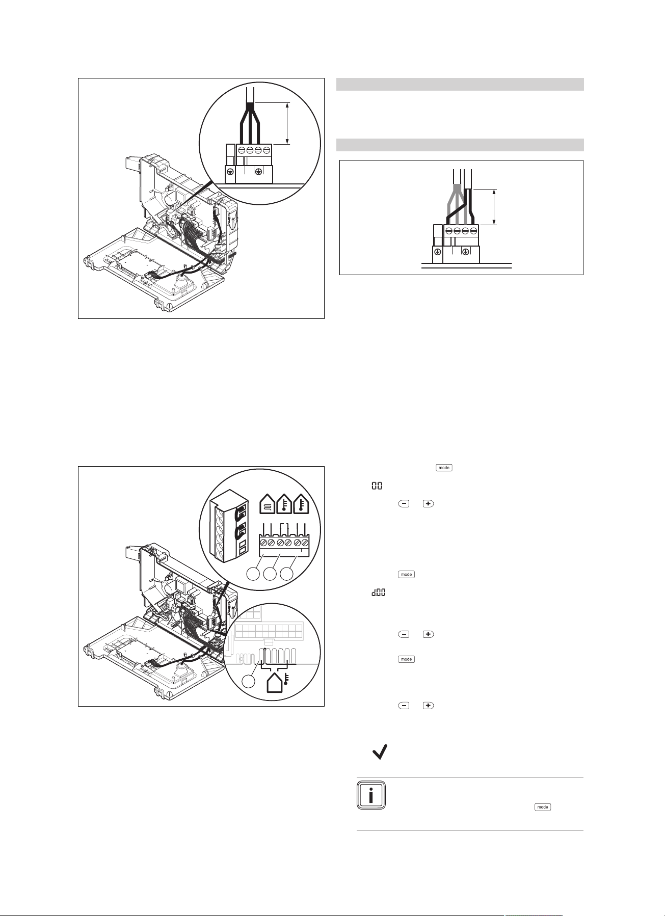
5.7.3 Carrying out the wiring
1. Shorten the connection cables to the appropriate
lengths to prevent them from causing damage inside
the electronics box.
2. Screw the plug to the connection cable.
3. Plug the plug into the slot provided on the PCB.
5.7.4 Establishing the power supply
1. To open the electronics box, follow the instructions in
the specified sequence.
2. To close the electronics box, follow the instructions in
reverse order.
5.7.2 Cable route
1 24-V eBUS cable route
2 230-V eBUS cable
route
1. Observe all relevant regulations.
– The applicable regulations state that the connection
must be made via an electrical partition with a contact opening of at least 3 mm at each pole.
2. Make sure that the rated voltage of the mains is 230 V.
3. Provide one common electricity supply for the boiler
and for the corresponding controller:
– Power supply: Single-phase, 230 V, 50 Hz
– Fuse protection: ≤ 3 A
4. Open the electronics box.
5. Observe the routing of the power supply cable (1) in the
electronics box in order to guarantee the strain relief.
14 Installation and maintenance instructions HOME 0020224355_00
Page 15
≤ 30 mm
NL
X1
230V~
RT
6. Carry out the wiring. (→ Page 14)
X2
X22
X41
–
+
24V=
RT BUS
Burner
off
X106
BUS24 V
BUSRTB.off
B
ur
ner
off
R
T
24V
=
-
+
B
U
S
1
4
32
≤ 30 mm
NL
X1
230V~
RT
7. Close the electronics box.
8. Screw the supplied plug to a three-core mains connection cable that complies with the relevant standards.
9. Connect the plug for the mains connection cable.
10. Make sure that access to the mains connection is al-
ways freely available and is not covered or blocked by
an obstruction.
5.7.5 Connecting controllers to the electronic
system
Operation 6
Conditions: If installing a multi-circuit controller.
▶ Change the pump operating mode (d.18) from Eco (in-
termittent pump operating mode) to Comfort (continuous
pump operating mode).
Conditions: If you are connecting a controller (230 V).
▶ Connect the controller to the main plug.
▶ Remove the bridge from the plug 24V=RT.
4. Close the electronics box.
6 Operation
6.1 Using diagnostics codes
You can use the parameters marked as adjustable in the
table of diagnostics codes to adapt the product to the system
and customer requirements.
Overview of diagnostics codes (→ Page 30)
6.1.1 Activating diagnostics codes
1.
Press and hold the button for 7 seconds.
◁
is shown in the display.
2.
Press the or button to set the value.
◁ The access code (96) is reserved for the competent
person.
◁ The access code (35) is reserved for the customer
service.
3.
Press the button to confirm.
◁
is shown in the display.
6.1.2 Setting a diagnostics code
1.
Press the or button to select the diagnostics
code.
2.
Press the button to confirm.
◁ The value and/or status of the diagnostics code is
shown in the display.
3.
Press the or button to set the value.
3 eBUS controller or radio
receiver unit
4 Outside temperature
sensor, wired
4. If you allow the value to flash for three seconds, the
setting is automatically confirmed.
◁
is shown in the display for 1 second.
Note
You can manually confirm the setting at any
time by pressing and holding the button
for less than 3 seconds.
1 Safety thermostat for
floor-standing heating
2 24 V controller
1. Open the electronics box.
2. Carry out the wiring. (→ Page 14)
3. Connect the individual components depending on the
type of installation.
0020224355_00 HOME Installation and maintenance instructions 15
Page 16
7 Start-up
5. Proceed accordingly for all parameters that need to be
changed.
6.
Press and hold the button for 3 seconds to finish
configuring the diagnostics codes.
◁ The display switches to the basic display.
6.2 Displaying the status codes
The status codes display the product's current operating
status.
Status codes – Overview (→ Page 34)
6.2.1 Activating the status codes display
1.
Hold the button down for more than 7 seconds.
◁ S.XX is shown on the display, followed by the heat-
ing flow temperature, the internal system pressure
and the cylinder temperature (depending on the version).
2.
Press the button to exit this menu.
◁ The display switches to the basic display.
6.3 Using check programmes
By activating various check programmes, you can trigger
various special functions on the product.
Check programmes – Overview (→ Page 30)
6.3.1 Calling up the check programmes
1.
Hold the button down for more than 5 seconds.
◁ All symbols are shown in the display.
◁
is shown in the display.
2.
Press and hold the button for five seconds.
◁
3.
Press the or button to select the check
programme.
4.
Press the button to confirm.
is shown in the display.
◁ on is shown in the display and the programme
starts.
5.
Press the and buttons at the same time whilst
running a check programme.
◁ The heating water temperature and the filling pres-
sure for the heating installation are shown alternately in the display.
6.
Press the button to return to the check programme.
◁ The display shows the check programme.
7.
Press the button to finish the check programme.
◁ OFF is shown in the display.
8.
Press and hold the button for 3 seconds to finish
the check programmes.
◁ End is shown in the display.
◁ The display switches to the basic display.
Note
If you do not press any button for 15 minutes,
the current programme is automatically cancelled and the basic display is shown.
6.3.2 Displaying the pressure and temperature of the heating during a check programme
1.
Press the buttons simultaneously.
◁ Display the filling pressure in the heating installation.
◁ Display the heating flow temperature.
2.
Press the button to display the check programme
currently running.
7 Start-up
7.1 Carrying out the initial start-up
Initial start-up must be carried out by a customer service
technician or an authorised competent person using the firstcommissioning-checklist. The first-commissioning-checklist
in the appendix (→ Page 43) of the installation instructions
must be filled in and stored carefully along with the unit's
documentation.
▶ Carry out the initial start-up using the first-commission-
ing-checklist in the appendix.
▶ Fill out and sign the first-commissioning-checklist.
7.2 Checking the factory setting
Caution.
Risk of material damage caused by mak-
ing unauthorised settings.
▶ Never modify the factory setting of the gas
pressure regulator of the gas valve.
The product combustion is checked on-site and pre-set to
the type of gas specified on the identification plate.
▶ Check the information about the type of gas indicated on
the identification plate and compare this with the type of
gas available at the installation location.
Conditions: The product model is not compatible with the local gas type.
▶ Do not start up the product.
Conditions: The product model is compatible with the local gas type.
▶ Proceed as described below.
16 Installation and maintenance instructions HOME 0020224355_00
Page 17

Start-up 7
7.3 Checking and treating the heating water/filling and supplementary water
Caution.
Risk of material damage due to poor-qual-
ity heating water
▶ Ensure that the heating water is of suffi-
cient quality.
▶ Before filling or topping up the system, check the quality
of the heating water.
Checking the quality of the heating water
▶ Remove a little water from the heating circuit.
▶ Check the appearance of the heating water.
▶ If you ascertain that it contains sedimentary materials,
you must desludge the system.
▶ Use a magnetic rod to check whether it contains mag-
netite (iron oxide).
▶ If you ascertain that it contains magnetite, clean the sys-
tem and apply suitable corrosion-protection measures, or
fit a magnet filter.
▶ Check the pH value of the removed water at 25 °C.
▶ If the value is below 6.5 or above 8.5, clean the system
and treat the heating water.
▶ Ensure that oxygen cannot get into the heating water.
(→ Page 20)
Checking the filling and supplementary water
▶ Before filling the system, measure the hardness of the
filling and supplementary water.
Treating the filling and supplementary water
▶ Observe all applicable national regulations and technical
standards when treating the filling and supplementary
water.
Provided the national regulations and technical standards
do not stipulate more stringent requirements, the following
applies:
You must treat the heating water in the following cases:
– If the entire filling and supplementary water quantity dur-
ing the operating life of the system exceeds three times
the nominal volume of the heating installation, or
– If the guideline values listed in the following table are not
met, or
– if the pH value of the heating water is less than 6.5 or
more than 8.5.
Total
heating
output
kW
< 50 < 300 < 3 200 2 2 0.02
> 50
to ≤ 200
> 200
to ≤ 600
> 600 2 0.02 2 0.02 2 0.02
1) Nominal capacity in litres/heating output; in the case of multiboiler systems, the smallest single heating output is to be used.
Water hardness at specific system volume
≤ 20 l/kW
ppm
CaCO₃
200 2 150 1.5 2 0.02
150 1.5 2 0.02 2 0.02
mol/m³ppm
> 20 l/kW
≤ 50 l/kW
CaCO₃
> 50 l/kW
mol/m³ppm
CaCO₃
1)
mol/
m³
Caution.
The use of unsuitable heating water may
cause aluminium corrosion and a resulting lack of leak-tightness.
In contrast to steel, grey cast iron or copper,
for example, aluminium reacts with alkaline
heating water (pH value > 8.5) to produce
substantial corrosion.
▶ When using aluminium, make sure that
the pH value of the heating water is
between 6.5 and a maximum of 8.5.
Caution.
Risk of material damage if the heating
water is treated with unsuitable additives.
Unsuitable additives may cause changes in
the components, noises in heating mode and
possibly subsequent damage.
▶ Do not use any unsuitable frost and cor-
rosion protection agents, biocides or sealants.
No incompatibility with our products has been detected to
date with proper use of the following additives.
▶ When using additives, follow the manufacturer's instruc-
tions without exception.
We accept no liability for the compatibility of any additive or
its effectiveness in the rest of the heating system.
Additives for cleaning measures (subsequent
flushing required)
– Fernox F3
– Sentinel X 300
– Sentinel X 400
Additives intended to remain permanently in the
system
– Fernox F1
– Fernox F2
– Sentinel X 100
– Sentinel X 200
Additives for frost protection intended to remain
permanently in the system
– Fernox Antifreeze Alphi 11
– Sentinel X 500
▶ If you have used the above-mentioned additives, inform
the operator about the measures that are required.
▶ Inform the operator about the measures required for frost
protection.
0020224355_00 HOME Installation and maintenance instructions 17
Page 18

7 Start-up
1
1
C
2
3
1
A
B
7.4 Avoiding danger arising from insufficient water pressure
The filling pressure must be between 0.10 and 0.15 MPa
(1.0 and 1.5 bar).
Note
If the heating flow temperature is shown in the
display, press and hold the and buttons
at the same time for longer than five seconds, or
temporarily deactivate heating mode in order to
display the pressure.
If the heating installation extends over several storeys,
higher filling pressures may be required to avoid air entering
the heating installation.
If the water pressure falls below 0.05 MPa (0.5 bar), the
value flashes in the display.
If the water pressure falls below 0.03 MPa (0.3 bar), the
product switches off. The display shows 0.0 MPa (0.0 bar).
Fault F22 will be stored in the fault list.
▶ Top up the water in the heating installation to start up the
product again.
◁ The pressure value flashes in the display until a
pressure of 0.05 MPa (0.5 bar) or higher has been
reached.
◁ An automatic air vent function is activated if the
pressure exceeds 0.05 MPa (0.5 bar) for longer than
15 seconds.
4. Purge each radiator until the water escapes normally,
and then retighten the system's purging valves.
5. Check that all connections are leak-tight.
Conditions: If the noise persists in the boiler
▶ Purge the product again by activating check programme
(P.07) and then (P.06).
Check programmes – Overview (→ Page 30)
7.7 Filling the condensate siphon
7.5 Switching on the product
▶ Switch on the product via the main switch installed on-
site.
7.6 Filling and purging the heating installation
Preliminary work
▶ Flush the heating installation through.
1. Check the silicone hose connection (1) between the
pump's automatic air vent and the hydraulic console.
2. Remove the caps from the automatic air vents.
3. Fill with water until the required filling pressure is
reached.
– Recommended filling pressure: 1 … 1.5 bar
◁ The heating and hot water functions cannot be activ-
ated.
◁ The pressure value flashes in the display until a
pressure of 0.05 MPa (0.5 bar) or higher has been
reached.
1. Unclip the lower section of the siphon (1) from the upper section of the siphon (2).
2. Remove the float (3).
3. Fill the lower section of the siphon with water up to 10
mm below the upper edge of the condensate drain pipework.
4. Re-insert the float (3).
Note
Check that the float is present in the condensate siphon.
5. Clip the lower section of the siphon (1) into the upper
section of the siphon (2).
7.8 Filling the hot water circuit
1. Open the water tap to fill the hot water circuit.
2. Close the water tap once the appropriate volume of
water has flowed out.
◁ The hot water circuit is filled.
3. Check all connections and the entire system for leaktightness.
18 Installation and maintenance instructions HOME 0020224355_00
Page 19

Start-up 7
1
2
7.9 Checking and adjusting the gas settings
Only a qualified competent person is authorised to implement the settings on the gas valve.
Each destroyed seal must be restored.
The CO2 adjusting screw must be sealed.
Never modify the factory setting of the gas pressure regulator of the gas valve.
7.9.1 Checking the gas connection pressure (gas flow pressure)
1. Ensure that the gas inlet working pressure can be
obtained with all other gas appliances in the property
working.
2. Close the gas isolator cock.
3. Undo the sealing screw on the measuring nipple (2).
4. Connect a pressure gauge to the measuring nipple (2).
5. Open the gas isolator cock.
6. Start up the product with check programme P.01.
7. In addition, ensure that maximum heat can be dissip-
ated into the heating system by turning up the room
thermostat.
8. With the boiler operating at full load check that the gas
inlet working pressure at the reference test point (2)
complies with the requirements.
Permissible connection pressure
Great Britain
9. Should the pressure recorded at the reference test point
in the boiler be lower than indicated check if there is
any blockage in the pipework or if the pipework is undersized.
Conditions: Gas flow pressure not in the permissible range
Natural gas G20
1.7 … 2 kPa
(17.0
… 20 mbar)
Caution.
Risk of material damage and operating
faults caused by incorrect gas connection pressure.
If the gas connection pressure lies outside
the permissible range, this can cause operating faults in and damage to the product.
▶ Do not make any adjustments to the
product.
▶ Do not start up the product.
▶ If you cannot correct the failure, notify the gas supply
company and proceed as follows:
▶ End check programme P.01.
▶ Allow the boiler to cool down by allowing pump overrun
to operate for a minimum of two minutes.
▶ Close the gas isolator cock.
▶ Remove the pressure gauge and retighten the sealing
screw (2) for the measuring nipple.
▶ Open the gas isolator cock (1).
▶ Check the measuring nipple for gas tightness.
▶ Close the gas isolator cock (1).
▶ Fit the front panel. (→ Page 10)
▶ Disconnect the product from the power mains.
▶ You must not start up the boiler.
Conditions: Gas flow pressure in the permissible range
▶ End the check programme P.01.
▶ Allow the boiler to cool down allowing pump overrun to
operate for a minimum of two minutes.
▶ Close the gas isolator cock (1).
▶ Remove the pressure gauge and retighten the sealing
screw (2) for the measuring nipple.
▶ Open the gas isolator cock (1).
▶ Check the measuring nipple for gas tightness.
▶ Fit the front panel. (→ Page 10)
▶ Reset boiler controls for normal operation.
▶ Record the appliance gas inlet working pressure (kPa
resp. mbar) in the Benchmark gas boiler commissioning
checklist.
7.9.2 Checking the leak-tightness of the flue gas system and for flue gas recirculation
1. Check that the flue gas system is intact, in accordance
with British Gas TB 200.
2. If the flue gas installation is longer than 2 m, a flue gas
recirculation test is strongly recommended. This test
must be carried out in accordance with the instructions
below.
3. Use the air analysis point (1) to check for flue gas recir-
culation.
4. Use the flue gas measuring instrument.
5. If you discover CO or CO2 in the fresh air, search for a
leak in the flue gas system or for the flue gas recirculation.
6. Eliminate the damage.
7. Repeat the above-mentioned test to determine if the
fresh air contains CO or CO2.
8. If you cannot eliminate the damage, you must not start
up the boiler.
7.9.3 Thoroughly flushing the heating installation
("hot")
1. Operate the appliance until the boiler and the heating
system are up to temperature.
2. Check the heating system for leaks.
3. Connect a hose to the drain valve located at the lowest
position of the heating system.
4. Shut off the boiler, open the drain valve and all purge
valves on the radiators and allow the water to flow out
of the heating system and the boiler quickly and fully.
5. Close the drain valve.
6. Fill and purge the heating installation. (→ Page 18)
7. Re-fill the system until the system design pressure of
0,1 MPa (1,0 bar) is attained.
0020224355_00 HOME Installation and maintenance instructions 19
Page 20

8 Adapting the unit to the heating installation
1
Note
The actual reading on the digital pressure
gauge should ideally be 0,05 MPa (0,5 bar)
plus an additional pressure corresponding
to the highest point of the system above the
base of the boiler – 10 m head equals an additional 1 bar reading on the pressure gauge.
The minimum pressure should not be less
than 0,1 MPa (1 bar) in any installation. If
the system is to be treated with an inhibitor it
should be applied at this stage in accordance
with the manufacturer’s instructions. Further
information can be obtained from Sentinel,
Betz Dearborn Ltd., Tel: 0151 420 9595, or
Fernox, Alpha– Fry technologies. Tel: 0870
8700362.
8. Fit the front panel. (→ Page 10)
7.9.4 Checking the CO₂ content
1. Start up the product with the check programme (P.01)
and set the value.
– Setting value for the programme P.01: 100
Check programmes – Overview (→ Page 30)
2. Wait until the value that is read is stable.
– Waiting period for reading a stable value: 5 min
7.10 Checking function and leak-tightness
Before you hand the product over to the operator:
▶ Check the gas line, the flue gas installation, the heating
installation and the hot water pipes for leaks.
▶ Check that the air/flue pipe and condensate drain pipe-
work have been installed correctly.
▶ Check that the front casing has been installed correctly.
7.10.1 Checking the heating mode
1. Activate the heating mode on the user interface.
2. Turn all thermostatic radiator valves on the radiators
until they are fully open.
3. Allow the product to operate for at least 15 minutes.
4. Purge the heating installation.
5. Activate the display for the current operating status.
(→ Page 16)
Status codes – Overview (→ Page 34)
◁ If the product is working correctly, the display shows
S.04.
7.10.2 Checking the hot water generation
1. Activate the hot water handling mode on the user interface.
2. Open a hot water valve completely.
3. Activate the display for the current operating status.
(→ Page 16)
Status codes – Overview (→ Page 34)
◁ If the product is working correctly, the display shows
S.14.
3. Unscrew the cover from the flue gas analysis point (1).
4. Measure the CO₂ content at the flue gas analysis point
(1).
5. Compare the measured value with the corresponding
value in the table.
Checking the CO₂ content
Great Britain
Removed
front casing/installed
front casing
Natural gas
G20
9.2 ±1 %
◁ The value is OK.
▽ The value is not OK; you cannot start up the
product.
▶ Inform Customer Service.
8 Adapting the unit to the heating
installation
You can reset/change the system parameters (section "Using diagnostics codes").
Overview of diagnostics codes (→ Page 30)
8.1 Burner anti-cycling time
To prevent frequent switching on and off of the burner and
thus prevent energy losses, an electronic restart lockout
is activated for a specific period each time the burner is
switched off. The burner anti-cycling time is only active for
the heating mode. Hot water handling mode during a burner
anti-cycling time does not affect the time function element.
8.1.1 Setting the maximum burner anti-cycling time
1. Set the diagnostics code. (→ Page 15)
Overview of diagnostics codes (→ Page 30)
2. If required, adjust the maximum burner anti-cycling time
using the diagnostics code d.02.
20 Installation and maintenance instructions HOME 0020224355_00
Page 21

Adapting the unit to the heating installation 8
21
3
4
60
70
50
30
20
40
10
0 500 1000 1500 A
B
21
34
60
70
50
30
20
40
10
0 500 1000 1500 A
B
21
34
60
70
50
30
20
40
10
0 500 1000 1500 A
B
1
8.1.2 Resetting the remaining burner anti-cycling time
▶
Hold the button down for more than 3 seconds.
◁
is shown in the display.
8.2 Setting the pump output
Conditions: Modulating pump
The product is equipped with a speed-regulated high-efficiency pump, which adjusts independently to the hydraulic
conditions of the heating installation.
If the heating installation is equipped with a low loss header,
switch off the speed control and set the pump output to a
fixed value.
▶ If required, use diagnostics code d.14 to adjust the set-
ting for the operating-mode-dependent pump speed.
▶ Set the diagnostics code. (→ Page 15)
Overview of diagnostics codes (→ Page 30)
Flow rate-pressure curves for 25 kW
(pressure measured downstream of the valves)
4 Flow rate at maximum
output (ΔT = 20K)
A Throughput in circuit
(l/h)
B Available pressure
(kPa)
Flow rate-pressure curves for 35 kW
(pressure measured downstream of the valves)
1 Maximum speed (by-
pass closed)
2 Maximum speed (de-
fault setting for the bypass)
3 Minimum speed (default
setting for the bypass)
4 Flow rate at maximum
output (ΔT = 20K)
A Throughput in circuit
(l/h)
B Available pressure
(kPa)
1 Maximum speed (by-
pass closed)
2 Maximum speed (de-
fault setting for the bypass)
3 Minimum speed (default
setting for the bypass)
4 Flow rate at maximum
output (ΔT = 20K)
A Throughput in circuit
(l/h)
B Available pressure
(kPa)
Flow rate-pressure curves for 30 kW
(pressure measured downstream of the valves)
8.3 Setting the bypass
Conditions: Modulating pump
If the pump operating parameter d.14 is set to Auto (∆p
limit), the default setting must not be changed.
Caution.
Risk of material damage caused by incor-
rect setting of the high-efficiency pump
When the pressure at the bypass valve is
increased (turning clockwise), malfunctions
may occur if the pump output is set below
100%.
▶ In this case, set the pump output to
5 = 100% using diagnostics parameter
d.14.
1 Maximum speed (by-
pass closed)
2 Maximum speed (de-
fault setting for the bypass)
0020224355_00 HOME Installation and maintenance instructions 21
3 Minimum speed (default
setting for the bypass)
▶ Regulate the pressure using the adjusting screw (1).
▶ Fit the front panel. (→ Page 10)
Page 22

9 Adjusting the hot water temperature
1
Position of the adjusting
screw
Right-hand stop (screwed
all the way in)
Mid-position (six anticlockwise rotations)
Five further anti-clockwise
rotations starting from the
mid-position
Notes/application
If the radiators do not heat
up sufficiently at the default
setting. In this case, you must
set the pump to the maximum
speed.
Default setting
If noises are produced in the
radiators or radiator valves.
9 Adjusting the hot water temperature
You can reset/change the system parameters (→ section
"Using diagnostics codes").
Overview of diagnostics codes (→ Page 30)
9.1 Setting the hot water temperature
Danger!
Risk of death from Legionella.
Legionella multiply at temperatures below
60 °C.
▶ Ensure that the operator is familiar with all
of the Anti-legionella measures in order
to comply with the applicable regulations
regarding legionella prevention.
11 Inspection and maintenance
11.1 Observing inspection and maintenance intervals
▶ Adhere to the minimum inspection and maintenance in-
tervals. Depending on the results of the inspection, it may
be necessary to bring maintenance work forward.
Inspection and maintenance work – Overview
(→ Page 40)
11.2 Procuring spare parts
The original components of the product were also certified
as part of the declaration of conformity. If you do not use certified Vaillant original spare parts for maintenance or repair
work, this voids the conformity of the product. We therefore
strongly recommend that you fit Vaillant genuine spare parts.
Information about available Vaillant original spare parts is
available by contacting the contact address provided on the
reverse of this document.
▶ If you require spare parts for maintenance or repair work,
use only Vaillant genuine spare parts.
11.3 Checking the CO₂ content
1. Start up the product with the check programme (P.01)
and set the value.
– Setting value for the programme P.01: 100
Check programmes – Overview (→ Page 30)
2. Wait until the value that is read is stable.
– Waiting period for reading a stable value: 5 min
▶ Set the hot water temperature.
Conditions: Water hardness: > 3.57 mol/m³
– Hot water temperature: ≤ 50 ℃
10 Handing the product over to the
operator
▶ When you have finished the installation, attach the sticker
supplied (in the operator's language) to the product
cover.
▶ Explain to the operator how the safety devices work and
where they are located.
▶ Inform the operator how to handle the product.
▶ In particular, draw attention to the safety information
which the operator must follow.
▶ Inform the operator of the necessity to have the product
maintained on a regular basis.
▶ Instruct the operator about measures taken to ensure the
supply of combustion air and flue gas pipe.
3. Unscrew the cover from the flue gas analysis point (1).
4. Measure the CO₂ content at the flue gas analysis point
(1).
5. Compare the measured value with the corresponding
value in the table.
Checking the CO₂ content
Great Britain
Removed
front casing/installed
front casing
Natural gas
G20
9.2 ±1 %
◁ The value is OK.
▽ The value is not OK; you cannot start up the
product.
▶ Set the CO₂ content. (→ Page 23)
22 Installation and maintenance instructions HOME 0020224355_00
Page 23

Inspection and maintenance 11
1
B
A
1
C
2
3
4
5
A
B
11.4 Setting the CO₂ content
Conditions: The CO₂ content must be adjusted
▶ Turn the screw (1) to set the CO₂ content (value with
front casing removed).
◁ To increase the CO₂ content: Turn anti-clockwise
◁ To decrease the CO₂ content: Turn clockwise
▶ Only carry out the adjustment in increments of 1/8 turn
and wait approximately 1 minute after each adjustment
until the value has stabilised.
▶ Compare the measured value with the corresponding
value in the table.
Setting the CO₂ value
Great Britain
Removed front casing/installed front
casing
Natural gas
G20
CO₂ at full
load
Set for
Wobbe
index W₀
O₂ at full
load
CO at full
load
CO/CO₂
9.2 ±0.2 %
14.09 kW⋅h/m³
4.5 ±1.8 vol. %
≤ 250 ppm
≤ 0.0027
11.5 Removing the gas-air mixture unit
Note
The gas-air mixture unit consists of three main
components:
– Ventilator
– Gas valve,
– Burner cover
1. Switch off the product via the main switch.
2. Close the gas isolator cock.
3. Push the clip (1) upwards.
4. Remove the flue pipe (2).
▽ If the setting is not in the specified adjustment range,
you must not start up the product.
▶ Inform Customer Service.
▶ Check whether the air-quality requirements with regard
to carbon monoxide are fulfilled.
▶ Install the front casing.
5. Remove the air intake pipe (3).
0020224355_00 HOME Installation and maintenance instructions 23
6. Remove the plugs from the gas valve (4) and from the
fan (5).
Page 24

11 Inspection and maintenance
A
C
D
B
6
7
7
8
1
1
2
3 4 5
B
A
1
C
2
7. Remove the gas-air mixture unit (6).
8. Remove the burner seals (7) and the burner (8).
9. Check the burner and the heat exchanger for damage
and dirt.
10. If necessary, clean or replace the components accord-
ing to the following sections.
11. Install the two new burner seals.
11.7 Checking the burner
1. Search the surface of the burner for possible damage. If
you see any damage, replace the burner.
2. Install the two new burner seals.
11.8 Checking the ignition electrode
1. Disconnect the connection (2) and the earthing cable
(1).
2. Remove the fixing screws (3).
3. Carefully remove the electrode from the combustion
chamber.
4. Check that the electrode ends (4) are undamaged.
5. Check the electrode distance.
– Clearance for the ignition electrodes: 3.5 … 4.5 mm
6. Make sure that the seal (5) is free from damage.
▽ If necessary, replace the seal.
11.9 Cleaning the condensate tray
1. Switch off the product via the main switch.
2. Close the gas isolator cock.
11.6 Cleaning the heat exchanger
1. Protect the folded down electronics box against sprayed
water.
2. Clean the ribs of the heat exchanger (1) with water.
◁ The water runs out into the condensate tray.
3. Push the clip (1) upwards.
4. Remove the flue pipe (2).
24 Installation and maintenance instructions HOME 0020224355_00
Page 25

1
5. Using water to clean the condensate tray (1).
C
2
3
1
A
B
1
3
2
3
2
4
◁ The water runs out into the condensate siphon.
11.10 Cleaning the condensate siphon
Inspection and maintenance 11
11.11 Cleaning the filter in the cold water inlet
1. Close the main cold water supply line.
2. Drain the product on the hot water side.
3. Remove the connection piece from the connection for
the product's cold water supply.
4. Clean the filter in the cold water inlet without removing
it.
11.12 Cleaning the heating filter
1. Unclip the lower section of the siphon (1) from the upper section of the siphon (2).
2. Remove the float (3).
3. Flush out the float and lower section of the siphon with
water.
4. Fill the lower section of the siphon with water up to 10
mm below the upper edge of the condensate drain pipework.
5. Reinsert the float (3).
Note
Check whether the float is present in the
condensate siphon.
1. Drain the product. (→ Page 26)
2. Remove the temperature sensor (3).
3. Remove the upper clip (1).
4. Remove the lower clip (2).
5. Remove the supply pipe (3).
6. Remove the heating filter (4) and clean it.
7. Reinstall the components in the reverse order.
6. Clip the lower section of the siphon (1) into the upper
section of the siphon (2).
0020224355_00 HOME Installation and maintenance instructions 25
Page 26

12 Troubleshooting
11.13 Installing the gas-air mixture unit
1. Install the burner.
2. Install the gas-air mixture unit.
3. Install the air intake pipe.
4. Install the flue pipe.
11.14 Draining the product
1. Close the service valves of the product.
2. Start check programme P.05 (→ Page 16).
Check programmes – Overview (→ Page 30)
3. Open the drain cock.
11.15 Checking the pre-charge pressure of the
expansion vessel
1. Drain the product. (→ Page 26)
2. Measure the pre-charge pressure of the expansion vessel at the vessel valve.
Conditions: Pre-charge pressure < 0.075 MPa (0.75 bar)
▶ Top up the expansion vessel in accordance with the
static height of the heating installation, ideally with nitrogen, otherwise with air. Check that the drain valve is
open when topping up.
3. If water escapes from the valve of the expansion
vessel, you must replace the expansion vessel
(→ Page 28).
4. Fill and purge the heating installation. (→ Page 18)
11.16 Completing inspection and maintenance
work
1. Fill and purge the heating installation. (→ Page 18)
2. Check the gas connection pressure (gas flow pressure).
(→ Page 19)
3. Check the CO₂ content. (→ Page 22)
12.2 Calling up the fault memory
The last ten fault codes are stored in the fault memory.
▶
Hold the button down for more than 7 seconds.
Overview of fault codes (→ Page 35)
▶
Press the button to exit this menu.
12.3 Deleting the fault memory
1. Delete the fault memory using the diagnostics code
d.94.
2. Set the diagnostics code. (→ Page 15)
Overview of diagnostics codes (→ Page 30)
12.4 Resetting parameters to factory settings
1. Reset all parameters to the factory settings using the
diagnostics code d.96.
2. Set the diagnostics code. (→ Page 15)
Overview of diagnostics codes (→ Page 30)
12.5 Preparing the repair work
1. Switch off the product.
2. Disconnect the product from the power mains.
3. Remove the front casing.
4. Close the gas isolator cock.
5. Close the service valves in the heating flow and in the
heating return.
6. Close the service valve in the cold water pipe.
7. Drain the product if you want to replace water-bearing
components of the product.
8. Ensure that water does not drip on live components
(e.g. the electronics box).
9. Use only new seals.
12.6 Replacing defective components
12.6.1 Replacing the burner
12 Troubleshooting
12.1 Rectifying faults
▶ If fault codes (F.XX) are present, refer to the table in the
appendix for advice or use the check programme(s).
Overview of fault codes (→ Page 35)
Check programmes – Overview (→ Page 30)
If several faults occur at the same time, the fault codes are
shown alternately on the display.
▶
Hold the button down for more than 3 seconds.
▶ If you are unable to clear the fault code and it reappears
despite several fault clearance attempts, contact customer service.
1. Remove the gas-air mixture unit. (→ Page 23)
2. Remove the burner seal.
3. Remove the burner.
4. Install the new burner complete with new seal on the
heat exchanger.
5. Install the gas-air mixture unit. (→ Page 26)
12.6.2 Replacing the gas-air mixture unit
1. Remove the gas-air mixture unit. (→ Page 23)
2. Install the new gas-air mixture unit (→ Page 26).
12.6.3 Replacing the gas valve
1. Disconnect the product from the power mains.
2. Close the gas isolator cock.
26 Installation and maintenance instructions HOME 0020224355_00
Page 27

B
D
E
A
C
5
6
7
3
2
1
4
3. Remove the air intake pipe (2).
1
A
B
1
2
3
5 4
A
B
2
2 3
B
1
A
1
A
2
3
4
4. Remove the plug from the gas valve (3) and from the
fan (4).
5. Unscrew the gas connection pipe's connection (1) from
the gas valve.
6. Undo the two screws (5).
7. Remove the gas valve (3).
8. Remove the seal (6) if it is still in place on the fan (7).
9. Install the new gas valve in reverse order.
10. Check the CO₂ content. (→ Page 22)
11. Set the CO₂ content. (→ Page 23)
Troubleshooting 12
3. Remove the temperature sensor (3).
4. Remove the upper clip (1).
5. Remove the lower clip (4).
6. Remove the supply pipe (5).
12.6.4 Replacing the heat exchanger
1. Remove the gas-air mixture unit. (→ Page 23)
2. Remove the gas pipe (1).
0020224355_00 HOME Installation and maintenance instructions 27
7. Remove the upper clip (1).
8. Remove the lower clip (3).
9. Remove the return pipe (2).
10. Remove the clip underneath the condensate tray (1).
11. Undo the four screws (2).
Page 28

12 Troubleshooting
1
3
2
4
A
C
B
D
E
1
2
B
C
1
2
3
A
D
C
C
D
B
A
A
12. Lift the heat exchanger up slightly and remove it together with the condensate tray (1).
13. Undo the four screws (3).
14. Remove the condensate tray.
15. Remove the ignition transformer (2).
16. Use the bolts to secure the condensate tray to the new
heat exchanger.
17. Install the new heat exchanger in reverse order.
12.6.5 Replacing the pump head
2. Undo the nut (3).
3. Remove both screws on the support plate (1).
4. Remove the support plate.
5. Pull out the expansion vessel (2) towards the front.
6. Insert a new expansion vessel into the product.
7. Screw the new expansion vessel onto the water connection. To do this, use a new seal.
8. Attach the support plate using both screws.
9. Fill and purge the product and, if necessary, the heating
installation.
12.6.7 Replacing the main PCB
1. Disconnect the pump cable from the electronics box.
2. Undo the four bolts (1).
3. Remove the pump head (2).
4. Replace the O-ring.
5. Use four screws to secure the new pump head.
6. Connect the pump cable to the electronics box.
12.6.6 Replacing the expansion vessel
1. Drain the product. (→ Page 26)
28 Installation and maintenance instructions HOME 0020224355_00
1. Open the electronics box.
2. Pull all of the plugs out from the PCB.
3. Undo the clips on the PCB.
4. Remove the PCB.
5. Install the new PCB in such a way that it clicks into the
groove at the bottom and into the clip at the top.
6. Plug in the PCB plugs.
7. Close the electronics box.
Page 29

Decommissioning the product 13
B
C
C
D
A
A
1
2
1
B
A
1
2
12.6.8 Replacing the PCB for the user interface
1. Open the electronics box.
2. Pull the plug out of the PCB.
3. Undo the clips on the PCB.
4. Remove the PCB.
5. Install the new PCB in such a way that it clicks into the
groove at the bottom and into the clip at the top.
6. Plug in the PCB plug.
7. Close the electronics box.
12.6.10 Replacing the flow sensor
1. Pull out the plug.
2. Remove the flow sensor (1).
3. Install the new flow sensor.
4. Plug in the plug.
12.6.11 Replace the pressure sensor
12.6.9 Replacing the expansion relief valve
1. Remove the clip (2).
2. Remove the expansion relief valve.
3. Fit the new expansion relief valve with a new O-ring.
4. Reattach the clip (2).
1. Pull out the plug.
2. Remove the clip (1).
3. Remove the pressure sensor (2).
4. Install the new pressure sensor.
5. Reattach the clip (1).
12.7 Completing repair work
▶ Check that the product is running correctly and that it is
completely leak-tight.
13 Decommissioning the product
▶ Decommission the product.
▶ Disconnect the product from the power mains.
▶ Close the gas isolator cock.
▶ Close the cold water stop cock.
▶ Drain the product. (→ Page 26)
14 Customer service
To ensure regular servicing, it is strongly recommended
that arrangements are made for a Maintenance Agreement.
Please contact Vaillant Service Solutions for further details.
Vaillant Service Solutions: 0330 100 3461
0020224355_00 HOME Installation and maintenance instructions 29
Page 30

Appendix
Appendix
A Check programmes – Overview
Note
Since the programme table is used for various products, some programmes may not be visible for the product in
question.
Display Meaning
P.01 Burner operation on adjustable heat input:
The product operates after ignition with the heat input set between "0" (0% = Pmin) and "100" (100% = Pmax).
The function is active for 15 minutes.
P.02 Burner operation at ignition load:
After ignition, the product works at ignition load.
The function is active for 15 minutes.
P.03 The product runs in heating mode with the maximum heat input set using diagnostics code d.00.
P.04 Maximum output function:
If there is a hot water request, the product runs in hot water handling mode and at maximum heat load.
If there is no hot water request, the product runs with the heating partial load that is set via diagnostics code
d.00 and in heating mode.
The function is active for 15 minutes.
P.05 Filling the product:
The diverter valve moves to the mid-position. The burner and pump switch off (to fill or drain the product).
If the pressure is lower than 0.03 MPa (0.3 bar) and then is above 0.05 MPa (0.5 bar) for longer than 15
seconds, the automatic purging function is activated.
The function is active for 15 minutes.
P.06 Purging the heating circuit:
The diverter valve is moved to the heating position.
The function is activated in the heating circuit for 15 minutes.
The pump runs and stops at regular intervals.
If required, this function can be manually switched off.
P.07 Purging the hot water circuit:
The function is activated in the small hot water circuit for 4 minutes and then in the heating circuit for 1 minute.
The pump runs and stops at regular intervals.
If required, this function can be manually switched off.
Automatic air vent
function
Purging the product:
If the pressure is lower than 0.03 MPa (0.3 bar) and then is above 0.05 MPa (0.5 bar) for longer than 15
seconds, the automatic purging function is activated.
The function is activated in the small hot water circuit for 4 minutes and then in the heating circuit for 1 minute.
This function cannot be manually switched off.
B Overview of diagnostics codes
Note
Since the code table is used for various products, some codes may not be visible for the product in question.
Diagnostics
code
d.00 Heating maximum output – – kW The maximum heating output
d.01 Pump overrun in heating
Parameter
mode
30 Installation and maintenance instructions HOME 0020224355_00
Values
Unit Increment, select, explanation
Min. Max.
varies depending on the product.
→ Section "Technical data"
Automatic: Unit automatically
adjusts the maximum output to
the current system demand
1 60 min 1 5 Adjustable
Default setting
→ Section
"Technical
data"
User-specific setting
Adjustable
Page 31

Appendix
Diagnostics
code
d.02 Maximum burner anti-
d.04 Water temperature in the
d.05 Determined heating flow
d.06 Hot water set target tem-
d.07 Set target temperature
d.08 Status of the 230 V ther-
d.09 Heating flow set target
d.10 Status of the internal
d.11 Status of the heating
d.13 Status of the hot water
d.14 Operating mode of the
d.15 Pump speed Current value % – – Not
d.16 Status of the 24 V room
d.17 Heating control – – – off = Flow temperature
d.18 Pump overrun operating
d.19 Pump operating mode, 2
Parameter
cycling time in heating
mode
cylinder
set target temperature
perature
for the domestic hot water cylinder
mostat
temperature that is set
on the eBUS room thermostat
pump in the heating circuit
circuit's shunt pump
circuit's circulation pump
modulating pump
thermostat
mode
stage pump
Values
Min. Max.
2 60 min 1 20 Adjustable
Current value ℃ – – Not
Current value
Current value ℃ (Combination unit only) – Not
Current value ℃ – – Not
Current value – 0 = Room thermostat open (no
Current value ℃ – – Not
Current value – off / on – Not
Current value – off / on – Not
Current value – off / on – Not
0 5 – 0 = variable rotational speed
Current value – off = Heating off
1 3 – 1 = Comfort (continuously operat-
0 3 – 0 = Burner mode stage 2, pump
Unit Increment, select, explanation
℃ – – Not
heat requirement)
1 = Room thermostat closed
(heat requirement)
(auto)
1; 2; 3; 4; 5 = Fixed rotational
speeds → Section "Setting the
pump output"
on = Heating on
on = Return temperature (adjustment for underfloor heating.
If you have activated the return
temperature control, the automatic heating output determination function is not active.)
ing pump)
3 = Eco (intermittent pump mode
– for the dissipation of the residual heat after hot water generation at an extremely low heat
demand)
flow/overrun stage 1
1 = Heating mode and pump
flow/overrun stage 1, hot water
handling mode stage 2
2 = Automatic heating mode,
pump flow/overrun stage 1, hot
water handling mode stage 2
3 = Stage 2
Default setting
– Not
0 Adjustable
– Not
0 Adjustable
1 Adjustable
3 Adjustable
User-specific setting
adjustable
adjustable
adjustable
adjustable
adjustable
adjustable
adjustable
adjustable
adjustable
adjustable
adjustable
0020224355_00 HOME Installation and maintenance instructions 31
Page 32

Appendix
Diagnostics
code
d.20 Maximum hot water set
d.21 Status of the warm start
d.22 Status of the hot water
d.23 Status of the heating
d.24 Status of the pressure
d.25 Status of the requirement
d.27 Function of relay 1
d.28 Function of relay 2
d.31 Automatic filling device 0 2 – 0 = Manual
d.33 Fan speed target value Current value rpm Fan speed = Display value x 100 – Not
d.34 Value for the fan speed Current value rpm Fan speed = Display value x 100 – Not
d.35 Position of the diverter
d.36 Value for the hot water
d.39 Water temperature in the
d.40 Heating flow temperature Current value ℃ – – Not
d.41 Heating return temperat-
d.43 Heating curve 0.2 4 – 0.1 1.2 Adjustable
Parameter
target temperature
for hot water
request
demand
monitor
to reheat the cylinder or
for the hot water warm
start from the eBUS thermostat
(multi-functional module)
(multi-functional module)
valve
flow
solar circuit
ure
Values
Unit Increment, select, explanation
Min. Max.
50 60 ℃ 1 50 Adjustable
Current value – off = Function deactivated
on = Function activated and
available
Current value – off = No current requirement
on = Current requirement
Current value – off = Heating off (Summer mode)
on = Heating on
0 1 – off = Not switched
on = Switched
Current value – off = Function deactivated
on = Function activated
1 10 – 1 = Circulation pump
2 = External pump
3 = Cylinder charging pump
4 = Extractor hood
5 = External solenoid valve
6 = External fault message
7 = Solar pump (omitted)
8 = eBUS remote control
9 = Legionella protection pump
10 = Solar valve
1 10 – 1 = Circulation pump
2 = External pump
3 = Cylinder charging pump
4 = Extractor hood
5 = External solenoid valve
6 = External fault message
7 = Solar pump (omitted)
8 = eBUS remote control
9 = Legionella protection pump
10 = Solar valve
1 = Semi-automatic
2 = Automatic
Current value – 0 = Heating
40 = Mid-position (parallel operation)
100 = Domestic hot water
Current value l/min – – Not
Current value ℃ – – Not
Current value ℃ – – Not
Default setting
– Not
– Not
– Not
– Not
– Not
1 Adjustable
2 Adjustable
0 Adjustable
– Not
User-specific setting
adjustable
adjustable
adjustable
adjustable
adjustable
adjustable
adjustable
adjustable
adjustable
adjustable
adjustable
adjustable
32 Installation and maintenance instructions HOME 0020224355_00
Page 33

Appendix
Diagnostics
code
d.45 Value for the base point
d.47 Outside temperature Current value ℃ – – Not
d.50 Correction of the min-
d.51 Correction of the max-
d.58 Solar circuit reheating 0 3 – 0 = Boiler's Legionella protection
d.60 Number of blocks by the
d.61 Number of unsuccessful
d.62 Night set-back 0 30 – 1 0 Adjustable
d.64 Average burner ignition
d.65 Maximum burner ignition
d.66 Activation of the warm
d.67 Remaining burner anti-
d.68 Number of unsuccessful
d.69 Number of unsuccessful
d.70 Operation of the diverter
d.71 Maximum heating flow
d.73 Correction of the hot wa-
d.75 Maximum cylinder re-
d.77 Max. cylinder reheating – – kW 1
d.80 Running time in heating
d.81 Running time in hot wa-
d.82 Number of burner igni-
d.83 Number of burner igni-
Parameter
of the heating curve
imum fan speed
imum fan speed
temperature limiter
ignitions
time
time
start function for hot water
cycling time (setting under d.02)
ignitions at 1st attempt
ignitions at 2nd attempt
valve
set target temperature
ter warm start temperature
heating time
mode
ter handling mode
tions in heating mode
tions in hot water handling mode
Values
Unit Increment, select, explanation
Min. Max.
15 30 – 1 20 Adjustable
0 3000 rpm 1
Fan speed = Display value x 10
-2500 0 rpm 1
Fan speed = Display value x 10
function deactivated
3 = Hot water activated (min.
target value 60 °C)
Current value – – – Not
Current value – – – Not
Current value s – – Not
Current value s – – Not
– – – off = Function deactivated
on = Function activated
Current value min – – Not
Current value – – – Not
Current value – – – Not
0 2 – 0 = Normal operating mode
(DHW and heating mode)
1 = Mid-position (parallel operation)
2 = Permanent setting: Heating
mode
45 80 ℃ 1 → Section
-15 5 K 1 0 Adjustable
20 90 min 1 45 Adjustable
→ Section "Technical data"
Current value h Running time = Display value x
100
Current value h Running time = Display value x
100
Current value – Number of ignitions = Display
value x 100
Current value – Number of ignitions = Display
value x 100
Default setting
600 Adjustable
-1000 Adjustable
0 Adjustable
1 Adjustable
0 Adjustable
"Technical
data"
– Adjustable
– Not
– Not
– Not
– Not
User-specific setting
adjustable
adjustable
adjustable
adjustable
adjustable
adjustable
adjustable
adjustable
Adjustable
adjustable
adjustable
adjustable
adjustable
0020224355_00 HOME Installation and maintenance instructions 33
Page 34

Appendix
Diagnostics
code
d.84 Maintenance in 0 3000 h Number of hours = Display value
d.85 Increase in the min. out-
d.88 Flow rate limit value
d.90 Status of the eBUS room
d.91 Status DCF77 Current value – – – Not
d.93 Setting the product code 0 99 – 1 – Adjustable
d.94 Delete fault list 0 1 – off = No
d.95 Software versions – – – 1 = Main PCB
d.96 Default setting (reset) – – – 0 = No
d.128 Heating minimum target
d.129 Minimum hot water tar-
Parameter
put (heating and hot water handling mode)
for ignition in hot water
handling mode
thermostat
value
get value
Values
Min. Max.
– – kW 1
0 1 – 0 = 1.7 l/min (no delay)
Current value – off = Not connected
10 75 ℃ 1 10 Adjustable
35
(com-
bination
unit)
45
(pure
boiler)
60 ℃ 1 35
Unit Increment, select, explanation
x 10
→ Section "Technical data"
1 = 3.7 l/min (2 s delay)
on = Connected
on = Yes
2 = Interface PCB
1 = Yes
Default setting
300 Not
– Adjustable
0 Adjustable
– Not
– Adjustable
– Adjustable
– Adjustable
(combination
unit)
45 (pure
boiler)
User-specific setting
adjustable
adjustable
adjustable
Adjustable
C Status codes – Overview
Note
Since the code table is used for various products, some codes may not be visible for the product in question.
Status code Meaning
Displays in heating mode
S.0 Heating mode: No requirement
S.01 Heating mode: Advance fan operation
S.02 Heating mode: Pump pre-run
S.03 Heating mode: Burner ignition
S.04 Heating mode: Burner on
S.05 Heating mode: Pump/fan overrun
S.06 Heating mode: Fan overrun
S.07 Heating mode: Pump overrun
S.08 Heating mode: Temporary shutdown after heating procedure
Displays in hot water handling mode
S.10 Hot water handling mode: Requirement
S.11 Hot water handling mode: Advance fan operation
S.13 Hot water handling mode: Burner ignition
S.14 DHW mode: Burner on
S.15 DHW mode: Pump/fan overrun
S.16 DHW mode: Fan overrun
34 Installation and maintenance instructions HOME 0020224355_00
Page 35

Appendix
Status code Meaning
S.17 DHW mode: Pump overrun
Display in Comfort mode with warm start or hot water handling mode with cylinder
S.20 Hot water handling mode: Requirement
S.21 Hot water handling mode: Advance fan operation
S.22 Hot water handling mode: Pump pre-run
S.23 Hot water handling mode: Burner ignition
S.24 DHW mode: Burner on
S.25 DHW mode: Pump/fan overrun
S.26 DHW mode: Fan overrun
S.27 DHW mode: Pump overrun
S.28 Hot water handling mode: Temporary shutdown of the burner
Other displays
S.30 Room thermostat is blocking heating mode.
S.31 No heating demand: Summer mode, eBUS controller, waiting period
S.32 Fan waiting time: Fan speed outside of the tolerance values
S.33 Forced fan operation until the pressure monitor is switched
S.34 Frost protection active
S.39 Underfloor heating contact open
S.41 Water pressure too high
S.42 Flue non-return flap closed
S.46 Protection mode: Minimum load
S.53 Product in waiting period/operation block function due to low water pressure (flow/return spread too large)
S.54 Waiting period: Low water pressure in the circuit (flow/return spread too large)
S.88 Product purging active
S.91 Maintenance: Demo mode
S.96 Automatic test programme: Return temperature sensor, heating and hot water request blocked.
S.97 Automatic test programme: Water pressure sensor, heating and hot water request blocked.
S.98 Automatic test programme: Return temperature sensor, heating and hot water request blocked.
S.99 Automatic filling active
S.108 Purging the combustion chamber, fan in operation
S.109 Product's standby mode activated
D Overview of fault codes
Note
Since the code table is used for various products, some codes may not be visible for the product in question.
Fault code Meaning Possible cause
F.00 Fault: Flow temperature sensor NTC plug not plugged in or has come loose, multiple plug on the PCB not
plugged in correctly, interruption in cable harness, NTC sensor defective
F.01 Fault: Return temperature sensor NTC plug not plugged in or has come loose, multiple plug on the PCB not
plugged in correctly, interruption in cable harness, NTC sensor defective
F.10 Short circuit: Flow temperature sensor NTC sensor defective, short circuit in the cable harness, cable/casing
F.11 Short circuit: Return temperature sensor NTC sensor defective, short circuit in the cable harness, cable/casing
F.13 Short circuit: Domestic hot water cylinder
temperature sensor
F.20 Safety switch-off: Overheating temperat-
ure reached
0020224355_00 HOME Installation and maintenance instructions 35
NTC sensor defective, short circuit in the cable harness, cable/casing
Incorrect earth connection between cable harness and product, flow or return
NTC defective (loose connection), black discharge via ignition cable, ignition
plug or ignition electrode
Page 36

Appendix
Fault code Meaning Possible cause
F.22 Safety switch-off: Low water pressure in
the boiler
F.23 Safety switch-off: Temperature difference
too great (NTC1/NTC2)
F.24 Safety switch-off: Temperature rise too
fast
F.25 Safety switch-off: Flue gas temperature
too high
F.27 Safety switch-off: Fault in flame detection Moisture on the electronics, electronics (flame monitor) defective, gas solen-
F.28 Fault: Ignition unsuccessful when startingupGas meter defective or gas pressure monitor has triggered, air in gas, gas
F.29 Fault: Flame loss Gas supply temporarily stopped, flue gas recirculation, incorrect earthing of
F.32 Fan frost protection function active: Fan
speed outside the tolerance values
F.33 Fan frost protection function active: Air
pressure switch fault
F.49 eBUS fault: Voltage too low Short circuit on eBUS, eBUS overload or two power supplies with different
F.61 Fault: Gas valve control system Short circuit/short to earth in cable harness for the gas valve, gas valve
F.62 Fault: Gas valve switch-off control Delayed switch-off of gas valve, delayed extinguishing of flame signal, gas
F.63 Fault: EEPROM Electronics defective
F.64 Fault: Electronics/sensor/analogue-to-
digital converter
F.65 Fault: Electronics temperature too high Electronics overheating due to external influences, electronics defective
F.67 Value sent back by ASIC is incorrect
(flame signal)
F.68 Fault: Unstable flame (analogue input) Air in gas, gas flow pressure too low, incorrect air ratio, incorrect gas re-
F.70 Invalid product code (DSN) Replace the screen and PCB at the same time without reconfiguring the
F.71 Fault: Flow/return temperature sensor Flow temperature sensor specifies a constant value: Flow temperature
F.72 Fault: Deviation in the water pressure
sensor/return temperature sensor
F.73 Fault: Water pressure sensor not con-
nected or has short-circuited
F.74 Fault: Electrical problem in the water
pressure sensor
F.75 Fault: Pressure sensor Pressure sensor or pump defective or low water pressure
F.77 Fault: Condensate or smoke No response, flue non-return flap defective
F.78 Interruption to DHW outlet sensor at
external controller
No or insufficient water in the product, water pressure sensor defective, cable to the pump or to the water pressure sensor loose/not
connected/defective
Pump blocked, insufficient pump output, air in product, flow and return NTC
sensors connected the wrong way round
Pump blocked, reduced pump output, air in product, system pressure too
low, return flow prevention blocked/incorrectly installed
Break in connection for optional flue gas safety temperature limiter (safety
cut-out), break in cable harness
oid valve leaking
flow pressure too low, thermal isolator device (TAE) has triggered, incorrect
gas restrictor, incorrect spare gas valve, fault on the gas valve, multiple plug
on PCB incorrectly plugged in, break in cable harness, ignition system (ignition transformer, ignition cable, ignition plug, ignition electrode) defective,
ionisation current interrupted (cable, electrode), incorrect earthing of product,
electronics defective
product, ignition transformer has spark failure
Plug on fan not correctly plugged in, multiple plug on PCB not correctly
plugged in, break in cable harness, fan blocked, Hall sensor defective, electronics defective
Pressure monitor has not switched or has switched at a fan speed value that
is too high (insufficient air supply)
Pressure monitor plug not correctly plugged in, pressure monitor defective,
line removed from between the pressure monitor and silencer, air/flue pipe
blocked and silencer not installed properly
polarities on the eBUS
defective (coils shorted to earth), electronics defective
valve leaking, electronics defective
Flow or return NTC short circuited, electronics defective
Implausible flame signal, electronics defective
strictor, ionisation flow interruption (cable, electrode)
product's Device Specific Number
sensor incorrectly attached to the flow pipe, flow temperature sensor defective
Flow/return NTC sensor temperature difference too great → flow and/or
return temperature sensor defective
Interruption/short circuit of water pressure sensor, interruption/short to earth
in supply line to water pressure sensor or water pressure sensor defective
Line to water pressure sensor has a short circuit to 5 V/24 V or internal fault
in the water pressure sensor
Link box connected, but hot water NTC not bridged
36 Installation and maintenance instructions HOME 0020224355_00
Page 37

Appendix
Fault code Meaning Possible cause
F.83 Fault: Burner temperature sensor Burner temperature sensor is defective
When the burner starts, the temperature change recorded by the flow or
return temperature sensor is non-existent or too small: Insufficient water in
the product, flow or return temperature sensor incorrectly attached to the
pipe
F.84 Fault: Flow/return temperature sensor Values not consistent, difference < -6 K
Flow and return temperature sensors signalling implausible values: Flow and
return temperature sensors have been inverted, flow and return temperature
sensors have not been correctly installed
F.85 Fault: Temperature sensor The flow and/or return temperature sensors have been installed on the same
pipe/incorrect pipe
Temperature sensor not connected or is connected incorrectly
F.86 Fault: Underfloor heating contact Underfloor heating contact open, sensor disconnected or defective
F.87 Fault: Ignition electrode Ignition electrode not connected or not connected properly, short circuit in
the cable harness
F.88 Fault: Gas valve Gas valve not connected or it is connected incorrectly, short circuit in the
cable harness
F.89 Fault: Pump Pump not connected or it is connected incorrectly, incorrect pump connec-
ted, short circuit in the cable harness
0020224355_00 HOME Installation and maintenance instructions 37
Page 38

Appendix
X2
X14
L
N
19
10
20
2
6
3
11
13
14
18
7
17
8
X51
X51
X20
16
1
9
3
15
4
5
10
11
6
13
X51 X35
X20
X40 X51
X30
X2
X21
X41
X22
X14
L
N
–
+
24V=
RT BUS
Burner
off
RT
230Vac
X1
FUS
X106
X32
X90
X12
X35
X1
X21
L
N
RT 230Vac
L
N
X35
1
3
4
1
3
3
1
2
M
1
3
4
6
1
2
3
eBUS
Burner off
X106
M
5
4
2
1
2
1
2
1
N
L
L
24V
230V~
24V
230V~
2
8
9
10
11
1312
1
5
4
3
6
7
15
14
E Connection diagram: Combination unit
9 3-way valve
10 Pressure sensor
11 Volume flow sensor
12 Ionisation electrode
13 Heating pump
14 Ignition electrode
15 Main power supply
1 Main PCB
2 Interface PCB
3 Timer
4 Control system
5 Temperature sensor in the heating flow
6 Temperature sensor in the heating return
7 Fan
8 Gas valve
38 Installation and maintenance instructions HOME 0020224355_00
Page 39

F Connection diagram: Combination unit (35 kW)
X20
X40 X51
X30
X2
X21
X41
X22
X14
L
N
–
+
24V=
RT BUS
Burner
off
RT
230Vac
X1
FUS
X106
X32
X90
X12
X35
X2
X14
L
N
19
10
20
2
6
3
11
13
14
18
7
17
8
X12
L
N
X51
X51
X20
16
1
9
3
15
4
5
10
11
6
13
X51
X1
X21
L
N
L
N
1
3
4
1
3
3
1
2
M
1
3
4
6
1
2
3
eBUS
Burner off
X106
M
4
3
2
1
5
4
2
1
5
6
7
8
2
1
2
1
N
L
X35
X35
24V
230V~
24V
230V~
2
8
9
10
11
13
12
1
5
4
6
7
15
14
3
Appendix
1 Main PCB
2 Interface PCB
3 Timer
4 Control system
5 Temperature sensor in the heating flow
6 Temperature sensor in the heating return
7 Fan
8 Gas valve
9 3-way valve
10 Pressure sensor
11 Volume flow sensor
12 Ionisation electrode
13 Heating pump
14 Ignition electrode
15 Main power supply
0020224355_00 HOME Installation and maintenance instructions 39
Page 40

Appendix
G Inspection and maintenance work – Overview
The table below lists the manufacturer requirements with respect to minimum inspection and maintenance intervals. If national regulations and directives require shorter inspection and maintenance intervals, you should observe these instead of
the intervals listed in the table.
Maintenance
No. Work
Check the air/flue pipe for leak-tightness and to ensure that it is fastened correctly. Make sure
1
that it is not blocked or damaged and has been installed in accordance with the relevant Installation Manual.
Check the general condition of the product. Remove any dirt from the product and the vacuum
2
chamber.
Visually inspect the general condition of the heat exchanger. In doing so, pay particular atten-
3
tion to signs of corrosion, rust and other defects. If you notice any damage, carry out maintenance work.
Check the gas connection pressure at maximum heat input. If the gas connection pressure is
4
not within the specified range, carry out maintenance work.
Check the CO₂ content (air ratio) of the product and, if necessary, adjust it.
5
Disconnect the product from the power mains. Check that the plug connections and electrical
6
connections are correct and make any necessary adjustments.
Close the gas isolator cock and the service valves.
7
Drain the product on the water side. Check the pre-charge pressure of the expansion vessel,
8
and top up the vessel if necessary (approx. 0.03 MPa/0.3 bar under the system filling pressure).
9 Check the ignition electrode. X X
Remove the gas-air mixture unit.
10
Replace both burner seals each time it is opened and accordingly each time maintenance
11
work is carried out.
Clean the heat exchanger.
12
→ Section "Cleaning the heat exchanger"
Check the burner for damage and replace it if necessary.
13
Check the condensate siphon in the product, clean it and, if required, replace it.
14
→ Section "Cleaning the condensate siphon"
Install the gas-air mixture unit. Caution: Replace the seals.
15
If necessary, if the hot water output is insufficient or the outlet temperature is not reached,
16
replace the plate heat exchanger.
Clean the filter in the cold water inlet. Replace the filter if impurities can no longer be removed
17
or if the filter is damaged. If this is the case, also check that the impeller sensor is not dirty or
damaged. Clean the sensor (do not use compressed air) and, if it is damaged, replace it.
Open the gas isolator cock, reconnect the product to the mains and switch it on.
18
If the automatic purging programme does not start, open the service valves, fill the product
19
or the heating installation to 0.1-0.2 MPa/1.0-2.0 bar (depending on the static height of the
heating installation) and manually start the purging programme P.07.
Perform a test operation of the product and heating installation, including hot water generation
20
(if available), and purge the system once more if necessary.
21 Check the CO₂ content (the air ratio) of the product again.
Ensure that no gas, flue gas, water or condensate is leaking from the product. Restore leak-
22
tightness if necessary.
Record the inspection/maintenance work carried out.
23
*Note: For those appliances which are not part of an annual service agreement/policy, maintenance must be carried out at least every
5 years.
Inspection
(annual)
X X
X X
X X
X X
X X
X X
X X
X X
X X
X X
X X
(must be
carried out at
regular
intervals)*
X
X
X
X
X
X
X
X
X
X
X
40 Installation and maintenance instructions HOME 0020224355_00
Page 41

H Opening in the air/flue pipe
G
N
N
MM
A
I
I
O
H
H
C
B
L
J
Q
Q
Q
Q
Q
K
P
D, E
F
I
S
R
T
Appendix
H.1 Positioning of the opening of a fan-supported flue gas pipe
Installation site
A
B Above an opening, air bricks, opening windows, etc., that can be opened. 300 mm
C Horizontally to an opening, air bricks, opening windows, etc., that can be opened. 300 mm
D
E Below eaves 200 mm
F Below balconies or car port roofs 200 mm
G From vertical wastewater pipes or down pipes 150 mm
H From external or internal corners 200 mm
I Above floors, roofs or balconies 300 mm
J From a surface facing a terminal 600 mm
K From a terminal facing a terminal 1,200 mm
L From an opening in the car port (e.g. door, window) which leads into the dwelling 1,200 mm
M Vertical from a terminal on the same wall 1,500 mm
N Horizontal from a terminal on the same wall 300 mm
O From the wall on which the terminal has been installed 0 mm
P From a vertical structure on the roof N/A
Q Above the roof area 300 mm
R Horizontal from adjacent windows on pitched or flat roofs 600 mm
S Above adjacent windows on pitched or flat roofs 600 mm
T Below adjacent windows on pitched or flat roofs 2,000 mm
Directly below an opening, air bricks, opening windows, etc., that can be opened. 300 mm
Below temperature-sensitive building components, e.g. plastic gutters, down pipes or wastewater
pipes
Minimum dimensions
75 mm
0020224355_00 HOME Installation and maintenance instructions 41
Page 42

Appendix
Balcony/eaves
Gutter
Adequately secured
air/flue gas pipe
The flue pipe must
protrude beyond any overhang
H.2 Text from BS 5440-1 on fan-supported flue gas pipes
BS 5440–1: It is recommended that the fanned flue gas system terminal is positioned as follows:
– At least 2 m from an opening in the building directly opposite, and
– So that the combustion products are not discharged directly across a property boundary.
– Dimensions D, E, F and G: These clearances may be reduced to 25 mm without affecting the performance of the boiler.
In order to ensure that the condensate vapour plume does not damage adjacent surfaces, the terminal should be extended as shown.
– Dimension H: This clearance may be reduced to 25 mm without adversely affecting the performance of the boiler. How-
ever, in order to ensure that the condensate vapour plume does not damage adjacent surfaces, a clearance of 300 mm is
preferred. For IE, recommendations are given in the current issue of the IS 813.
H.3 Opening of the flue pipe below eaves and balconies
42 Installation and maintenance instructions HOME 0020224355_00
Page 43

I Commissioning Checklist
© Heating and Hotwater Industry Council (HHIC)
www.centralheating.co.uk
Benchmark Commissioning and
Servicing Section
It is a requirement that the boiler is installed and commissioned to the
completed in full.
Appendix
0020224355_00 HOME Installation and maintenance instructions 43
Page 44

Appendix
This Commissioning Checklist is to be completed in full by the competent person who commissioned the boiler as a means of demonstrating
compliance with the appropriate Building Regulations and then handed to the customer to keep for future reference.
GAS BOILER SYSTEM COMMISSIONING CHECKLIST
CONTROLS
Optimum start control
Fitted
Fitted
Fitted
Fitted
ALL SYSTEMS
Yes
Yes
CENTRAL HEATING MODE
OR
mbar OR mbar
COMBINATION BOILERS ONLY
Yes
Yes
DOMESTIC HOT WATER MODE
OR
mbar OR mbar
Yes Temperature
CONDENSING BOILERS ONLY
Yes
ALL INSTALLATIONS
AND
²
Ratio
AND
²
Ratio
Yes
Yes
Yes
Yes
44 Installation and maintenance instructions HOME 0020224355_00
Page 45

It is recommended that your heating system is serviced regularly and that the appropriate Service Interval Record is completed.
Service Provider
SERVICE RECORD
SERVICE 01
AND
²
%
AND
²
%
SERVICE 02
AND
²
%
AND
²
%
SERVICE 03
AND
²
%
AND
²
%
SERVICE 04
AND
²
%
AND
²
%
SERVICE 05
AND
²
%
AND
²
%
SERVICE 06
AND
²
%
AND
²
%
SERVICE 07
AND
²
%
AND
²
%
SERVICE 08
AND
²
%
AND
²
%
SERVICE 09
AND
²
%
AND
²
%
SERVICE 10
AND
²
%
AND
²
%
Appendix
0020224355_00 HOME Installation and maintenance instructions 45
Page 46

Appendix
PRIOR TO CO AND COMBUSTION RATIO CHECK
The boiler manufacturer’s installation instructions should have been followed, gas type verified and gas
supply pressure/rate checked as required prior to commissioning.
As part of the installation process, especially where a flue has been fitted by persons other than the
boiler installer, visually check the integrity of the whole flue system to confirm that all components are
correctly assembled, fixed and supported. Check that manufacturer’s max. flue lengths have not been
exceeded and all guidance has been followed (e.g. Gas Safe Technical Bulletin TB008).
The flue gas analyser should be of the correct type, as specified by BS 7967
Prior to its use, the flue gas analyser should have been maintained and calibrated as specified by the
manufacturer. The installer must have the relevant competence for use of the analyser.
Check and zero the analyser IN FRESH AIR as per analyser manufacturer’s instructions.
NOTE
THE AIR GAS RATIO VALVE IS FACTORY
SET AND MUST NOT BE ADJUSTED
DURING COMMISSIONING UNLESS THIS
ACTION IS RECOMMENDED FOLLOWING
CONTACT WITH THE MANUFACTURER.
If any such adjustment is recommended and
further checking of the boiler is required the
installer/service engineer must be competent
to carry out this work and to use the flue gas
analyser accordingly.
If the boiler requires conversion to operate with
a different gas family (e.g. conversion from
natural gas to LPG) separate guidance will be
provided by the boiler manufacturer
CARRY OUT FLUE INTEGRITY CHECK USING ANALYSER
Insert analyser probe into air inlet test point and allow readings to stabilise.
NOTE - where no air inlet test point is provided then a flue integrity check
with the analyser is not possible. The installer should verify that flue
integrity has been visually checked in accordance with the “Prior to CO
and combustion ratio check” box above before proceeding to the
“Check CO and combustion ratio at maximum rate” stage below.
SET BOILER TO MINIMUM RATE
In accordance with boiler instructions, set boiler to operate at minimum rate (to
minimum load condition). Allow sufficient time for combustion to stabilise.
NOTE - If manufacturer’s instructions do not specify how to set boiler to minimum
rate contact Technical Helpline for advice.
CHECK CO AND COMBUSTION RATIO AT MINIMUM RATE
With boiler still set at minimum rate, insert analyser probe into flue gas sampling
point. Allow readings to stabilise before recording.
NOTE - If no flue gas sampling point is present and the correct procedure is not
specified in the manual, consult boiler manufacturer for guidance.
CHECK CO AND COMBUSTION RATIO AT MAX. RATE
With boiler still set at maximum rate, insert analyser probe into flue gas
sampling point. Allow readings to stabilise before recording.
NOTE - If no flue gas sampling point is present and the correct procedure is
not specified in the manual, consult boiler manufacturer for guidance.
SET BOILER TO MAXIMUM RATE
In accordance with boiler instructions, set boiler to operate at max. rate
(full load condition). Allow sufficient time for combustion to stabilise.
NOTE - Do not insert analyser probe during this period to avoid
possible “flooding” of sensor.
Is
CO less than
350ppm and
CO/CO
2
ratio
less than 0.004
Is
O2 ≥ 20.6%
and
CO2 < 0.2%
Is
CO less than
350ppm and
CO/CO
2
ratio
less than 0.004
BOILER IS OPERATING SATISFACTORILY
no further actions required.
Ensure test points are capped, boiler case is correctly replaced and
all other commissioning procedures are completed.
Complete Benchmark Checklist, recording CO and combustion ratio
readings as required.
TURN OFF APPLIANCE AND CALL
MANUFACTURER’S TECHNICAL HELPLINE
FOR ADVICE.
THE APPLIANCE MUST NOT BE
COMMISSIONED UNTIL PROBLEMS ARE
IDENTIFIED AND RESOLVED.
VERIFY FLUE INTEGRITY
Analyser readings indicate that combustion products
and inlet air must be mixing. Further investigation of
the flue is therefore required.
Check that flue components are assembled, fixed
and supported as per boiler/flue manufacturer’s
instructions.
Check that flue and flue terminal are not obstructed.
Is
CO less than
335ppm
and
CO/CO2 ratio less
than 0.004
Is
O2 ≥ 20.6%
and
CO
2
< 0.2%
Check all seals around the appliance burner,
internal flue seals, door and case seals.
Rectify where necessary.
TURN OFF APPLIANCE AND CALL
MANUFACTURER’S TECHNICAL HELPLINE
FOR ADVICE.
THE APPLIANCE MUST NOT BE
COMMISSIONED UNTIL PROBLEMS ARE
IDENTIFIED AND RESOLVED. IF
COMMISSIONING CANNOT BE FULLY
COMPLETED, THE APPLIANCE MUST BE
DISCONNECTED FROM THE GAS SUPPLY IN
ACCORDANCE WITH THE GSIUR.
NOTE: Check and record CO and combustion ratio
at both max. and min. rate before contacting the
manufacturer.
NO
NO
NO
NO
NO
YES
YES
YES
YES
YES
J Combustion chart
46 Installation and maintenance instructions HOME 0020224355_00
Page 47

K Lengths of the air/flue pipe
Length of the C13 type flue pipe
HOME COMBI 25 -A (H-GB)
Length
of
HOME COMBI 30 -A (H-GB)
the
air/flue
HOME COMBI 35 -A (H-GB)
pipe
Length of the C33 type flue pipe
HOME COMBI 25 -A (H-GB)
Length
of
HOME COMBI 30 -A (H-GB)
the
air/flue
HOME COMBI 35 -A (H-GB)
pipe
Length of the C43 type flue pipe
HOME COMBI 25 -A (H-GB)
Length
of
HOME COMBI 30 -A (H-GB)
the
air/flue
HOME COMBI 35 -A (H-GB)
pipe
Appendix
C13 type flue pipe
Dia. 60/100 (L) Dia. 80/125 (L)
≤ 10 m ≤ 25 m
≤ 10 m ≤ 25 m
≤ 6 m ≤ 19 m
C33 type flue pipe
Dia. 60/100 (L) Dia. 80/125 (L)
≤ 10 m ≤ 25 m
≤ 10 m ≤ 25 m
≤ 10 m ≤ 19 m
C43 type flue pipe
Dia. 60/100 (L)
≤ 10 m
≤ 10 m
≤ 10 m
L Technical data
Technical data – Heating
HOME COMBI
25 -A (H-GB)
Maximum heating flow temperature (default setting)
Max. range of the flow temperature regulation
Maximum permissible pressure
Nominal water flow (ΔT = 20 K)
Nominal water flow (ΔT = 30 K)
Approximate value for the
condensate volume (pH value
between 3.5 and 4.0) at 50/30 °C
ΔP heating at nominal flow (ΔT =
20 K) – (bypass default setting)
ΔP heating at nominal flow (ΔT =
20 K) – (bypass closed)
Technical data – G20 power/loading G20
Maximum heat output (default setting – d.00)
Effective output range (P) at
50/30 °C
75 ℃ 75 ℃ 75 ℃
10 … 80 ℃ 10 … 80 ℃ 10 … 80 ℃
0.3 MPa
(3.0 bar)
655 l/h 655 l/h 655 l/h
436 l/h 436 l/h 436 l/h
1.53 l/h 1.53 l/h 1.53 l/h
0.025 MPa
(0.250 bar)
0.041 MPa
(0.410 bar)
HOME COMBI
25 -A (H-GB)
Automatic Automatic Automatic
5.3 … 15.9 kW 6.3 … 15.9 kW 7.4 … 15.9 kW
HOME COMBI
30 -A (H-GB)
0.3 MPa
(3.0 bar)
0.025 MPa
(0.250 bar)
0.039 MPa
(0.390 bar)
HOME COMBI
30 -A (H-GB)
HOME COMBI
35 -A (H-GB)
0.3 MPa
(3.0 bar)
0.025 MPa
(0.250 bar)
0.042 MPa
(0.420 bar)
HOME COMBI
35 -A (H-GB)
0020224355_00 HOME Installation and maintenance instructions 47
Page 48

Appendix
HOME COMBI
25 -A (H-GB)
Effective output range (P) at
80/60 °C
Hot water heat output range (P)
Maximum heat input – heating (Q
max.)
Minimum heat input – heating (Q
min.)
Maximum heat input – hot water
(Q max.)
Minimum heat input – hot water (Q
min.)
5.1 … 15.2 kW 6.1 … 15.2 kW 7.1 … 15.2 kW
5 … 25.2 kW 6 … 30 kW 7 … 35 kW
15.3 kW 15.3 kW 15.3 kW
5.1 kW 6.1 kW 7.1 kW
25.7 kW 30.6 kW 35.7 kW
5.1 kW 6.1 kW 7.1 kW
Technical data – Domestic hot water
HOME COMBI
25 -A (H-GB)
Specific flow rate (D) (ΔT = 30 K)
in accordance with EN 13203
Continuous flow rate (ΔT = 35 K)
Specific flow rate (ΔT = 35 K)
Minimum permissible pressure
Maximum permissible pressure
Temperature range
Throughflow volume limiter
12.1 l/min 14.5 l/min 16.8 l/min
622 l/h 746 l/h 864 l/h
10.4 l/min 12.4 l/min 14.4 l/min
0.03 MPa
(0.30 bar)
1 MPa
(10 bar)
35 … 60 ℃ 35 … 60 ℃ 35 … 60 ℃
10 l/min 12 l/min 14 l/min
HOME COMBI
30 -A (H-GB)
HOME COMBI
30 -A (H-GB)
0.03 MPa
(0.30 bar)
1 MPa
(10 bar)
HOME COMBI
35 -A (H-GB)
HOME COMBI
35 -A (H-GB)
0.03 MPa
(0.30 bar)
1 MPa
(10 bar)
Technical data – General
Diameter of the gas pipe
Diameter of the heating pipe
Expansion relief valve connector
(min.)
Condensed water discharge pipe
(min.)
G20 gas supply pressure
Gas flow at P max. – hot water
(G20)
CE number (PIN)
Smoke mass flow in heating mode
at P min.
Smoke mass flow in heating mode
at P max.
Smoke mass flow in hot water
handling mode at P max.
Released system types
Nominal efficiency at 80/60 °C
Nominal efficiency at 50/30 °C
Nominal efficiency in partial load
operation (30%) at 40/30 °C
NOx class
Product dimensions, width
Product dimensions, depth
Product dimensions, height
HOME COMBI
25 -A (H-GB)
1/2 inch 1/2 inch 1/2 inch
3/4 inch 3/4 inch 3/4 inch
15 mm 15 mm 15 mm
21.5 mm 21.5 mm 21.5 mm
20 mbar 20 mbar 20 mbar
2.7 m³/h 3.2 m³/h 3.8 m³/h
CE-0063CP3646 CE-0063CP3646 CE-0063CP3646
2.34 g/s 2.80 g/s 3.26 g/s
6.9 g/s 6.9 g/s 6.9 g/s
11.6 g/s 13.8 g/s 16.1 g/s
C13, C33, C43,
C53
99.5 % 99.5 % 99.5 %
104 % 104 % 104 %
108.5 % 108.5 % 108.5 %
5 5 5
418 mm 418 mm 418 mm
300 mm 300 mm 300 mm
740 mm 740 mm 740 mm
HOME COMBI
30 -A (H-GB)
C13, C33, C43,
C53
HOME COMBI
35 -A (H-GB)
C13, C33, C43,
C53
48 Installation and maintenance instructions HOME 0020224355_00
Page 49

Appendix
Net weight
Weight when filled with water
Technical data – Electrics
Electric connection
Built-in fuse (slow-blow)
Max. electrical power consumption
Standby electrical power consumption
Level of protection
HOME COMBI
25 -A (H-GB)
32 kg 32.6 kg 32.7 kg
36 kg 37.1 kg 37.2 kg
HOME COMBI
25 -A (H-GB)
230 V / 50 Hz 230 V / 50 Hz 230 V / 50 Hz
T2/2A, 250V T2/2A, 250V T2/2A, 250V
105 W 110 W 120 W
2 W 2 W 3 W
IPX4D IPX4D IPX4D
HOME COMBI
30 -A (H-GB)
HOME COMBI
30 -A (H-GB)
HOME COMBI
35 -A (H-GB)
HOME COMBI
35 -A (H-GB)
0020224355_00 HOME Installation and maintenance instructions 49
Page 50

Index
Index
A
Air/flue pipe ....................................................................... 12
Installing.........................................................................12
Air/flue pipe, installed ............................................................ 5
Article number ....................................................................... 7
B
Burner anti-cycling time ....................................................... 20
C
Calling up the fault memory................................................. 26
CE label................................................................................. 8
Check programmes........................................................... 30
Using..............................................................................16
Checking the burner ............................................................24
Checking the pre-charge pressure of the expansion
vessel ..................................................................................26
Cleaning the condensate siphon ......................................... 25
Cleaning the heat exchanger .............................................. 24
CO₂ content
Checking.................................................................. 20, 22
Combustion air ...................................................................... 5
Completing inspection work ................................................26
Completing maintenance work ............................................26
Completing repair work .......................................................29
Completing, repair work ......................................................29
Condensate drain pipework................................................. 12
Condensate siphon
Filling ............................................................................. 18
Controller............................................................................. 15
Controlling the bypass ......................................................... 21
Corrosion............................................................................... 5
D
Decommissioning................................................................ 29
Decommissioning the product .............................................29
Diagnostics codes
Using..............................................................................15
Documents ............................................................................7
Draining the product ............................................................26
E
Electricity ............................................................................... 5
Expansion relief valve .........................................................29
F
Fault codes.......................................................................... 26
Fault symbol........................................................................16
Flow rate-pressure curves ................................................... 21
Flow sensor.........................................................................29
Flue gas route .......................................................................5
Flue pipe equipment connection piece................................ 12
Front casing, closed .............................................................. 5
Frost ......................................................................................5
H
Handing over to the operator............................................... 22
I
Identification plate ................................................................. 7
If you smell gas .....................................................................4
Inspection work ............................................................. 22, 40
Installation site.......................................................................5
Intended use.......................................................................... 4
M
Mains connection ................................................................ 14
Maintenance work ......................................................... 22, 40
P
Power supply....................................................................... 14
Preparing the repair work .................................................... 26
Preparing, repair work .........................................................26
Pressure sensor .................................................................. 29
Pump ................................................................................... 21
Pump head..........................................................................28
Pump output
Setting............................................................................21
R
Regulations ........................................................................... 6
Removing the air intake pipe...............................................23
Removing the burner ........................................................... 23
Removing the flue pipe........................................................ 23
Removing the gas-air mixture unit....................................... 23
Removing the ignition transformer ...................................... 23
Removing the side section .................................................. 10
Replacing the burner ...........................................................26
Replacing the expansion vessel..........................................28
Replacing the gas valve ...................................................... 26
Replacing the heat exchanger............................................. 27
Replacing the main PCB ..................................................... 28
Replacing the PCB for the user interface............................ 29
Replacing, expansion vessel............................................... 28
Resetting the burner anti-cycling time................................. 21
S
Safety device......................................................................... 5
Schematic drawing................................................................5
Serial number........................................................................7
Setting the burner anti-cycling time ..................................... 20
Spare parts.......................................................................... 22
Switching on the product ..................................................... 18
T
Tool .......................................................................................6
Transport ............................................................................... 5
Transporting ..........................................................................8
Treating the heating water .................................................. 17
U
Unloading the box .................................................................8
Unpacking the product ..........................................................8
Using
Check programmes .......................................................16
Diagnostics codes.......................................................... 15
V
Voltage ..................................................................................5
W
Weight ...................................................................................9
50 Installation and maintenance instructions HOME 0020224355_00
Page 51

Page 52

0020224355_00 14.10.2015
Vaillant Ltd.
Nottingham Road Belper Derbyshire DE56 1JT
Telephone 0330 100 3461 Telephone (renewables) 0207 022 0928
Vaillant Service Solutions 0330 100 3461 Spares Technical Enquiries 01773 596615
info@vaillant.co.uk technicalspares@groupservice.co.uk
www.vaillant.co.uk
© These instructions, or parts thereof, are protected by copyright and may be reproduced or distributed only with
the manufacturer's written consent.
 Loading...