

Page 1

geoTHERM
VWS/VWW
GB; ES
Page 2

Page 3

For the owner
Operating manual
geoTHERM
Heat pump
VWS/VWW
GB
Page 4

Contents
Contents
General information ..................................................... 3
Data badge .............................................................................. 3
1 Information on this manual ............................. 3
1.1 Other applicable documents .................................. 3
1.2 Storage of the documents ...................................... 3
1.3 Symbols used ............................................................. 4
1.4 Applicability of the manual ..................................... 4
2 Safety instructions .......................................... 4
2.1 Coolants ....................................................................... 4
2.2 Prohibition on alterations ....................................... 5
3 Equipment and functional description ........... 5
3.1 Functional principle .................................................. 5
3.2 Operation mode of the coolant circuit ................ 6
3.3 Automatic auxiliary functions ................................ 6
3.4 Design of the heat pump ......................................... 7
4 Notes on the installation and operation ........ 8
4.1 Intended use ............................................................... 8
4.2 Requirements of the installation site .................. 9
4.3 Accumulation of condensate
(condensation water) ............................................... 9
4.4 Energy saving tips .................................................... 9
4.4.1 General energy saving tips ..................................... 9
4.4.2 Economising by using the control
system correctly ........................................................ 10
5.12.4 Warning messages .................................................... 25
5.12.5 Temporary malfunctions ......................................... 26
5.12.6 Blocking error ............................................................ 26
6 Warranty and customer service ..................... 27
6.1 Vaillant warranty....................................................... 27
6.3 Vaillant Service .......................................................... 27
7 Appendix ............................................................ 28
7.1 Technical Data VWS ................................................. 28
7.2 Technical Data VWW ................................................ 29
7.3 Data badge .................................................................. 31
5 Operation ........................................................... 11
5.1 Familiarising yourself with and operating
the controller ............................................................. 11
5.2 Setting menus and parameters ............................. 12
5.3 Description of the controller .................................. 12
5.3.1 Possible system circuits .......................................... 12
5.3.2 Energy balance controller ...................................... 13
5.3.3 Charging principle buffer cylinder ........................ 13
5.3.4 Resetting to factory settings ................................. 13
5.3.4 Controller structure ................................................. 13
5.3.5 Adjusting the energy saving functions ................ 13
5.4 Flow diagram .............................................................. 14
5.5 Displays at user level ............................................... 15
5.6 Installer Menu ............................................................ 21
5.7 Starting up the heat pump ..................................... 23
5.8 Shutting down the heat pump ............................... 23
5.9 Inspection by a specialist engineer ...................... 23
5.10 Inspection by the operator ..................................... 23
5.10.1 Checking the filling pressure of the
heating system .......................................................... 23
5.10.2 Checking the filling level and filling pressure
of the brine circuit .................................................... 24
5.11 Cleaning and care .................................................... 24
5.12 Troubleshooting and diagnosis ............................. 25
5.12.1 Error messages on the controller ......................... 25
5.12.2 Activating emergency mode .................................. 25
5.12.3 Errors/malfunctions that you can remedy ......... 25
Operating Manual geoTHERM VWS/VWW 0020051578_012
Page 5
N
General information
Information on this manual 1
General information
Vaillant geoTHERM heat pumps are generally referred
to in this manual as heat pumps. This operating manual
is valid for the following variants:
Type name Article number
Brine/Water Heat Pumps
VWS 220/2 0010002797
VWS 300/2 0010002798
VWS 380/2 0010002799
VWS 460/2 0010002800
Water/Water Heat Pumps
VWW 220/2 0010002801
VWW 300/2 0010002802
VWW 380/2 0010002803
VWW 460/2 0010002804
Table 0.1 Type designations and article numbers
The heat pumps state-of-the-art appliances
which have been constructed in accordance
with recognised safety regulations.
Conformity with the applicable standards has
been demonstrated.
VDE and tested safety
With the CE mark, we confirm as equipment manufacturers that the appliances in the geoTHERM range satisfy the requirements of the Directive on Electromagnetic
Compatibility (Council Directive 89/336/EWG).
The appliances meet the basic requirements of the
Low Voltage Directive (Council Directive 73/23/EEC).
Furthermore, the appliances satisfy the requirements of
EN 14511 (Heat pumps with electrically-driven compressors, heating, specifications for appliances for space
heating and for warming drinking water) as well as
EN 378 (safety and environmentally related specifications for refrigerating systems and heat pumps).
Data badge
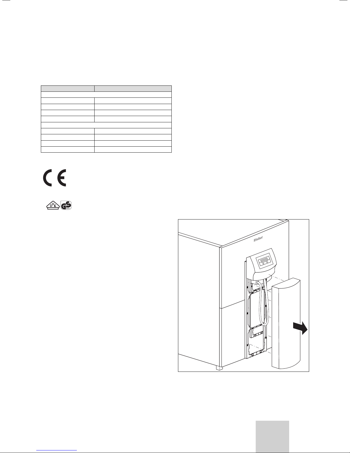
The geoTHERM heat pump has an identification plate
which is mounted on the front face of the magnetic
steel sheet. The type designation is on the front cladding at the top of the unit (also see Fig. 3.3, Pos. 1).
In the appendix to Chap. 7.3 there is a picture of an
identification plate for customers who are interested
in the technical aspects of the system, and also a table
explaining the symbols shown on it.
1 Information on this manual
This manual contains important information on how
to operate your heat pump safely and professionally.
1.1 Other applicable documents
Other applicable documents are all manuals that describe the operation of the heat pump, and the manuals
supplied with the accessories used.
1.2 Storage of the documents
Store this operating manual and all related documents
in such a way that they are available whenever required.
You can store the documents inside the pillar cover.
If you move out or sell the appliance, pass on the documents to the buyer.
1
L
2
L
3
L
N
E
P
1
L
2
L
3
L
N
E
P
1
L
2
L
3
L
N
E
P
F
OTA
F
C
D
- +
AufZu
NL
HK2-P HK2 VF2 RF1 VF1 SP BUSDCF/AF EVU1xZPLP/UV 1
NL
SK2-P
NL
ZP
NNAufZuL N 121212121212
ZH
2 345SC
L LLL L1 LNNNN N 2N2121LN
1
B
678AS
H
0
-3
8
A
B
B
A
1
-0
0
-3
8
A
B
B
A
1
-0
0
-3
12
A
B
B
A
1
-0
0
-3
12
A
B
B
A
1
-0
0
-3
2
1
A
B
B
A
1
-0
0
-3
8
A
B
B
A
1
-0
Fig. 1.1 Removing the pillar cover
GB
3Operating Manual geoTHERM VWS/VWW 0020051578_01
Page 6

1 Information on this manual
2 Safety instructions
1.3 Symbols used
The following symbols are used in this operating manual
to denote levels of danger, information, activities and
energy-saving tips.
Danger!
Immediate risk of serious injury or
d
death!
Danger!
Danger of burning and scalding!
H
Caution!
Potentially dangerous situation for the
a
product and environment!
Note
Useful information and instructions.
h
This symbol points you to energy saving tips. You can
put this setting into effect by means of the heat pump
control system, among other things.
• Symbol for a necessary task
1.4 Applicability of the manual
This manual applies exclusively to heat pumps with the
type designations listed in Table 0.1.
2 Safety instructions
Observe the following safety instructions and regulations when operating the heat pump:
• Take advantage of the extensive instruction in the
operation of the heat pump provided by your
specialist technician.
• Carefully read through this operating manual.
• Only carry out activities that are described in this
operating manual.
2.1 Coolants
The heat pump is delivered with an operational filling of
R 407 C coolant. This is a chlorine-free coolant which
does not affect the Earth's ozone layer. R 407 C is neither a fire hazard nor an explosion risk.
Danger!
Environmental hazard!
a
d
h
This unit contains R 407 C coolant. The
coolant must not be allowed to escape
into the atmosphere. R 407 C is a fluorinated, chlorine-free greenhouse gas that
has been included in the Kyoto Protocol,
with a GWP of 1653 (GWP = Global
Warming Potential).
Before the appliance is disposed of, the
coolant it contains must be completely
drained into a suitable vessel so that it
can then be recycled or disposed of in
accordance with the regulations.
The relevant work in connection with the
coolant may only be carried out by officially certified specialists.
Danger!
Risk of injury from freezing as a result
of contact with the R 407 C coolant!
Escaping coolant can cause freezing if
the exit point is touched:
Do not inhale gases or vapours emanating from leaks in the coolant circuit.
Avoid contact with the skin and eyes.
Note
R 407 C coolant presents no danger
during normal use and under normal
conditions. With improper use, however,
it can cause injury and damage.
Danger!
Risk of burning as a result of contact
H
with heat pump components!
High temperatures can appear on heat
pump components.
Do not touch any uninsulated pipes on
the heat pump.
Do not remove any of the cladding
sections (apart from the pillar cover,
see Chap. 1.2).
Operating Manual geoTHERM VWS/VWW 0020051578_014
Page 7
Safety instructions 2
Equipment and functional description 3
If an external passive cooling system is installed in your
system:
Caution!
Danger of falling below the dew point and
a
a
2.2 Prohibition on alterations
d
condensate formation!
The heating flow temperature setting
must not be too low in cooling mode. The
cooling function is still effective with a
flow temperature of 20 °C.
Caution!
The cooling function is impaired if the
thermostatic radiator valves are closed!
The thermostatic radiator valves must
be switched to the "open" position in
cooling mode to ensure that the cooled
heating water circulates smoothly
through the underfloor circuit.
Danger!
Inappropriate alterations can cause
injuries!
Under no circumstances should you
attempt to make changes or alterations
to the heat pump or other parts of the
heating and hot water system yourself.
3 Equipment and functional
description
3.1 Functional principle
Heat pump systems consist of separate circuits in which
liquids or gases transport the heat from the heat source
to the heating system. As these circuits operate with
differing media (brine/water, coolant and heating
water), they are coupled to one another by means of
heat exchangers. In these heat exchangers the heat
passes from a medium at a high temperature to a
medium at a lower temperature.
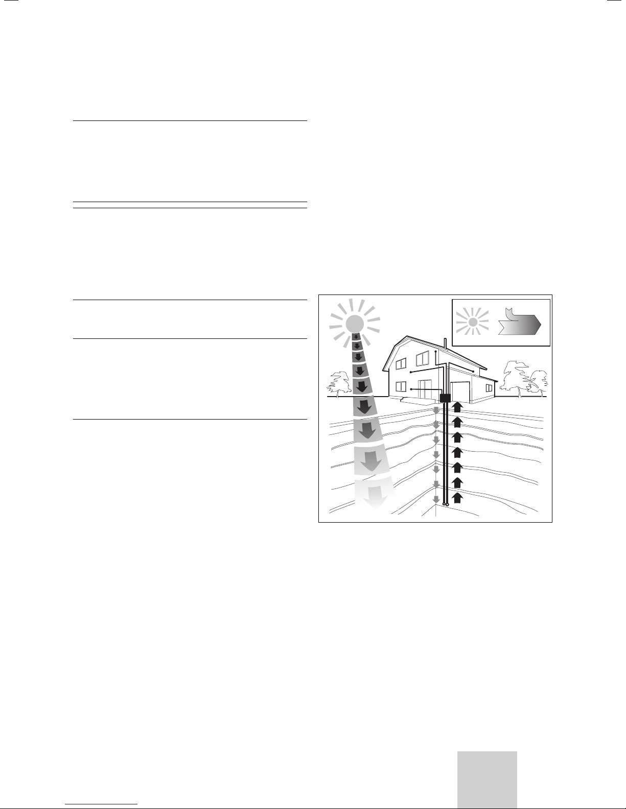
The Vaillant geoTHERM heat pump uses geothermal
energy or ground water as its heat source.
1/4 Electrical energy
3/4 Environmental energy 4/4 Heating energy
The prohibition applies to:
— the heat pump,
— the vicinity of the heat pump,
— the supply lines for water and power.
For alterations to the heat pump or its peripherals, you
must call on a qualified engineer.
• Do not damage or remove seals or locking devices on
components. Only suitably qualified heating engineer
or our customer service may remove sealed components.
Fig. 3.1 Use of geothermal energy or ground water as the heat
source
The system consists of separate circuits which are coupled to one another by means of heat exchangers.
These circuits are:
- The heat source circuit, by means of which the energy
from the heat source is transported to the coolant
circuit.
- The coolant circuit, which releases its heat to the
heating water circuit by means of evaporation, compression, liquefaction and expansion.
- The heating water circuit, which supplies the heating
and the hot water generation for the domestic hot
water cylinder.
GB
5Operating Manual geoTHERM VWS/VWW 0020051578_01
Page 8
3 Equipment and functional description
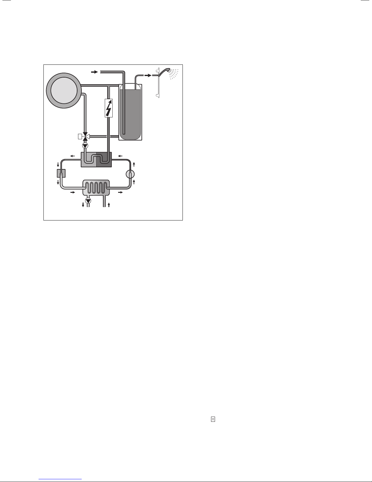
3.2 Operation mode of the coolant circuit
Cold water
Hot water
Heating system
Additional
heating
Domestic
hot water cylinder
Switching valve
Heating water pump
3
Expansion valve
4
Brine pump
Fig. 3.2 Principle of operation of the heat pump
Condenser
Evaporator
Heat source
Compressor
1
Heating water circuit
2
Coolant circuit
Heat source circuit
The coolant circuit is connected by means of the evaporator (1) to the environmental heat source, from which it
extracts thermal energy. At the same time, the physical
state of the coolant changes; it evaporates. The coolant
circuit is connected by means of the condenser (3) to
the heating system, to which it releases the heat again.
In so doing, the coolant becomes liquid again; it condenses.
As thermal energy can only pass from a body at a higher temperature to a body at a lower temperature, the
coolant in the evaporator must have a lower temperature than the environmental heat source. On the other
hand, the temperature of the coolant in the condenser
must be higher than that of the heating water in order
to be able to release the heat to it.
These different temperatures are produced in the coolant circuit by means of a compressor (2) and an expansion valve (4) between the evaporator and condenser.
The coolant flows in vapour form from the evaporator
into the compressor, where it is compressed. This causes the pressure and temperature of the coolant vapour
to rise sharply. After this process it flows through the
condenser, where it releases its heat to the heating
water by condensation. It flows as a liquid to the expansion valve, where it expands significantly and in so doing
loses much of its pressure and temperature. This temperature is now lower than that of the brine flowing
through the evaporator. The coolant can thus take up
more heat in the evaporator, turning into vapour in the
process and flowing to the compressor. The cycle starts
again.
If required, the electric auxiliary heating can be
switched in by the integrated controller.
To prevent the formation of condensate in the interior
of the unit, the pipes of the heat source circuit and the
coolant circuit are insulated. In the unlikely event that
condensate forms, this collects in a condensate pan inside the unit and is discharged under the unit where a
suitable condensate drain should be installed.
3.3 Automatic auxiliary functions
Frost protection
The controller is equipped with a frost protection function. This function ensures that your heating installation
is protected from frost in all operating modes.
The set-back temperature is pre-set automatically for
each heating circuit if the outside temperature falls
below 3 °C.
Cylinder frost protection
This function starts automatically when the actual temperature of the cylinder falls below 10 °C. The cylinder is
then heated to 15 °C. This function is also active in the
"Off" and "Auto" operating modes, regardless of the
timer programmes.
Checking the external sensors
The hydraulic basic circuit given by you during commissioning determines the required sensors. The heat pump
constantly checks automatically that all sensors are installed and functioning.
Protection from loss of heating water
An analogue pressure sensor monitors possible low
water pressure and switches the heat pump off if the
water pressure on the pressure gauge reads less than
0.5 bar and switches it back on when the water pressure
is over 0.7 bar on the pressure gauge.
Pump seizing and valve seizing protection
To prevent the heating, circulation or brine pumps, or
the hot water diverter valve UV1, from seizing, those
pumps and the valve that have not been in operation for
the last 24 hours are turned on in sequence for approximately 20 seconds every day.
Protection against loss of brine (VWS only)
An analogue pressure sensor monitors possible low
brine pressure and switches the heat pump off if the
brine pressure is ever less than 0.2 bar on the pressure
gauge and error 91 is displayed on the error memory.
The heat pump switches on again when the brine pressure rises above 0.4 bar gauge pressure.
If the brine pressure drops below 0.6 bar on the pressure gauge for more than one minute a warning appears
in menu
1.
Operating Manual geoTHERM VWS/VWW 0020051578_016
Page 9
Equipment and functional description 3
Floor protection circuit for all hydraulics without
buffer cylinder (e.g. in hydraulic plans 1 and 3)
If the measured flow temperature in the underfloor
heating circuit continuously exceeds a specific value for
more than 15 minutes, the heat pump switches off and
issues the error message 72. When the heating flow
temperature falls below this value again and the error
has been reset the heat pump switches back on.
Caution!
Danger of damage to the floor.
a
Set the value for the floor protection
circuit ensuring that it is not high
enough to damage the floor as a result
of excessively high temperatures.
Phase monitoring
The sequence and existence of phases (clockwise rotating field) on the 400 V voltage supply are continuously
monitored during commissioning and operation. If the
sequence is not correct or if a phase breaks down, the
heat pump is switched off due to the error to avoid
damage to the compressor.
Freezing protection function
The outlet temperature of the heat source is constantly
measured. If the heat source outlet temperature falls
below a specific value, the compressor temporarily
shuts off with the error message 20 or 21. If these errors occur three times in a row there is a fault-induced
shutdown.
For the geoTHERM VWS heat pumps you can set the
value (Default setting -10 °C) for the freezing protection
in the installation assistant A4.
For the geoTHERM VWW heat pumps a default value of
+4 °C is set. This value cannot be changed.
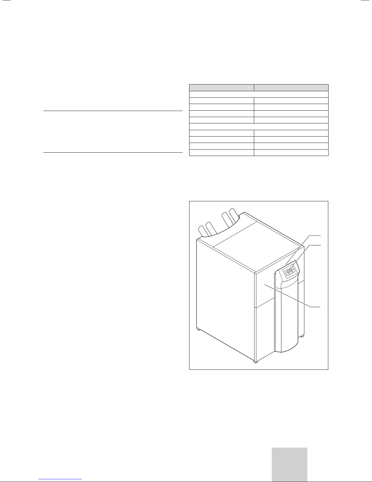
3.4 Design of the heat pump
The types of heat pump available are listed below. The
heat pumps are, above all, different from each other in
their output.
Type name Heating output (kW)
Brine-to-water heat pumps (B0/W35)
VWS 220/2 21.6
VWS 300/2 29.9
VWS 380/2 38.3
VWS 460/2 45.9
Water-water heat pumps (W10/W35)
VWW 220/2 29.9
VWW 300/2 41.6
VWW 380/2 52.6
VWW 460/2 63.6
Table 3.1 Type summary
1)
Thermal heating output with a brine temperature of 0 °C and
heating flow temperature of 35 °C
2)
Thermal heating output with a water temperature of 10 °C and
heating flow temperature of 35 °C
1)
2)
1
2
Fig. 3.3 Front view VWS/VWW
Key to Fig. 3.3
1 Label with heat pump type designation
2 Operating panel
3 Serial number
GB
3
7Operating Manual geoTHERM VWS/VWW 0020051578_01
Page 10
3 Equipment and functional description
4 Notes on the installation and operation
4 Notes on the installation and
operation
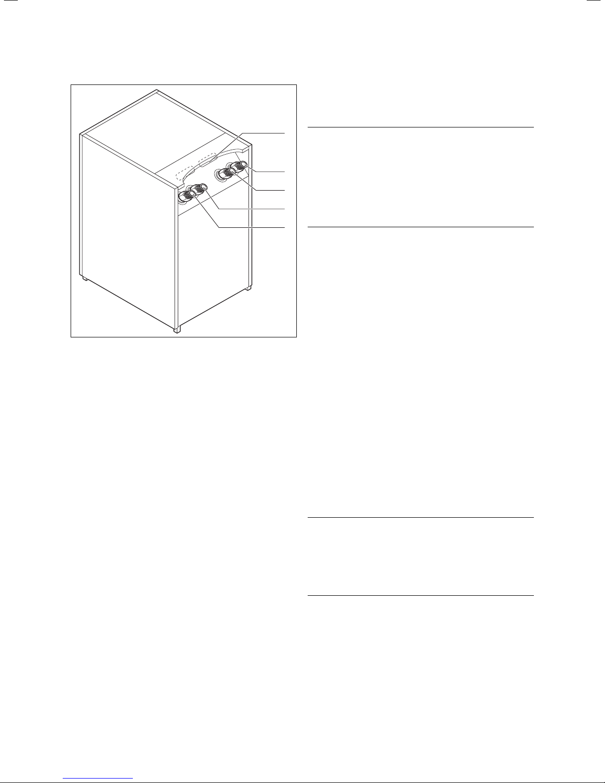
Fig. 3.4 Rear view VWS/VWW
Key to Fig. 3.4
1 Cable feedthrough for electrical connections
2 Heat source from the heat pump
3 Heat source to the heat pump
4 Heating return
5 Heating feed
1
d
2
3
4
5
4.1 Intended use
The Valliant geoTHERM heat pump has been built using
state-of-the-art technology in accordance with recognised safety regulations. Nevertheless, there is still a
risk of injury or death to the user or others or of damage to the device and other property in the event of improper use or use for which it is not intended.
This unit is not intended for use by persons (including
children) having limited physical, sensory or mental capacities or who have inadequate experience and/or
knowledge, unless supervised by a person responsible
for their safety or who has been given instructions from
them as to how to operate the unit.
Children must be supervised to ensure that they do not
play with the unit.
The heat pump is designed to generate heat for closed
hot water central heating installations and for hot water
generation. Any other use or extended use is considered
to be improper. The manufacturer or supplier is not liable for any resulting damage. The user alone bears the
risk.
Intended use also includes:
— observance of the operating and installation manual.
— observance of all other applicable documents.
— compliance with the inspection and care conditions.
Danger!
Risk to life as a consequence of using
unqualified personnel!
Installation, inspection and repair may
only be carried out by a qualified engineer. In particular, working on the electrical components and on the coolant
circuit requires an appropriate qualification.
d
Danger!
Danger of death due to improper use of
the system.
There is a risk of death or serious injury
to the user or others or of damage to the
unit and other property in the unit is improperly used or not used as intended.
Operating Manual geoTHERM VWS/VWW 0020051578_018
Page 11

Notes on the installation and operation 4
4.2 Requirements of the installation site
The installation site must be dimensioned such that the
heat pump can be properly installed and maintained.
• Ask your heating engineer which currently applicable
national building regulations must be observed.
The installation site must be dry and generally frostproof.
4.3 Accumulation of condensate
(condensation water)
The evaporator, the brine pumps and the pipes in the
heat source circuit, as well as some components in the
coolant circuit, are insulated in the interior of the heat
pump, so that no condensate can accumulate. If in the
unlikely event of a small amount of condensate forming,
this falls into an internal condensate pan in the bottom
section of the heat pump. As a result of the heat generated inside the heat pump, the condensate in the condensate pan evaporates. Small amounts of the accumulating condensate can be drained off under the heat
pump. In small amounts, accumulating condensate
should not be seen as a fault in the heat pump.
If an external passive cooling system is installed in your
system:
Caution!
Danger of falling below the dew point and
a
condensate formation!
The heating flow temperature setting
must not be too low in cooling mode. The
cooling function is still effective with a
flow temperature of 20 °C.
4.4 Energy saving tips
Below you will find important tips to help you operate
your heat pump system in an energy and cost-saving
manner.
4.4.1 General energy saving tips
You can even save energy through your general actions:
—Ventilate correctly:
Do not leave windows or French doors tilted open.
Instead, open these wide 3 to 4 times a day for
15 minutes and turn down the thermostatic valves
or room thermostats while ventilating.
— Do not block the radiators:
this will allow the heated air in the room to circulate
more effectively.
— Use a ventilation system with heat recovery:
The optimum exchange of air in the building is always
guaranteed by using a ventilation system with heat
recovery (windows no longer need to be opened for
ventilation purposes). If necessary, the air flow can be
matched to your individual requirements with the ventilation unit's remote control.
— Check that windows and doors are airtight:
Keep shutters and blinds closed at night, so that as
little heat as possible is lost.
— Do not cover controllers:
If a VR 90 remote control unit is installed as an accessory, do not obstruct it with furniture, etc. as otherwise it will not be able to record the circulating room
air as effectively.
— Awareness of water usage:
shower instead of bath, replace seals in dripping water
taps immediately, for example.
GB
9Operating Manual geoTHERM VWS/VWW 0020051578_01
Page 12

4 Information on the installation and operation
—Use thermostatic radiator valves:
You can adjust the room temperature to suit your in-
4.4.2 Economising by using the control system cor-
rectly
Further economies can be made by the correct use of
the control system on your heat pump.
A number of tips on how to make save energy by adjusting your heat pump's control system are provided
below:
— Set the correct heating flow temperature:
Your heat pump not only controls the heating flow
temperature with reference to the outside temperature, it also controls the heating flow temperature
with reference to the room temperature you have set.
Therefore select a room temperature that is just sufficient for your comfort, for example 20 °C. Every degree over and above that means an increase in energy
consumption of around 6 % per annum.
— Select the appropriate heating curve:
If your heat pump is used to operate underfloor heating, you should specify a heating curve that is less
than 0.4. We recommend that radiator heating systems are configured in such a way that they can still
function effectively at extremely low outside temperatures with a maximum flow temperature of 50 °C; this
corresponds to heating curves of less than 0.7.
— Choose an appropriate hot water temperature set-
ting:
The hot water set target temperature you specify
should be just enough to satisfy your consumption
requirements and no higher. Any further heating
results in unnecessary power consumption, and hot
water temperatures of more than 60 °C also lead to
increased lime scale production. We recommend that
hot water generation be achieved without the electric
auxiliary heating; by this method, the maximum hot
water temperature is determined by the high pressure
cut-out in the heat pump cooling circuit. This cut-out
corresponds to a maximum hot water temperature of
approx. 58 °C.
— Setting of heating times that take individual re-
quirements into account:
Use the timer programs for heating and hot water. Set
the times on the basis of your typical daily routine and
corresponding heat demand.
— Select the correct operating mode:
For the times that you are asleep or away, we recom-
mend that you switch the heating to set-back mode.
—Heat uniformly:
Through appropriate structuring of a heating pro-
gramme, you can arrange for all the rooms in your
house to be uniformly heated in accordance with your
pattern of use.
dividual requirements and ensure effective operation
of your heating installation using the thermostatic
valves in combination with a room temperature regulator (weather compensator).
— Optimise use of the circulation pump:
Adapt the operating times of the circulation pump to
actual requirements.
— Consult your expert technician:
He can adjust your heat pump installation to suit your
personal requirements.
You will find these and other energy saving tips in
Chap. 5.5. The controller settings that can potentially
save energy are described there.
Operating Manual geoTHERM VWS/VWW 0020051578_0110
Page 13
5 Operation
5.1 Familiarising yourself with and operating the
controller
All programming of the heat pump is carried out by
means of the two dials (
The dial
is used to select the parameter (by pressing)
and to alter the parameter
(by turning). The dial
(by turning) and to activate special functions (by pressing).
and ) on the controller.
is used to select the menu
Operation 5
1
Basic data
Date
Day of week
6
5
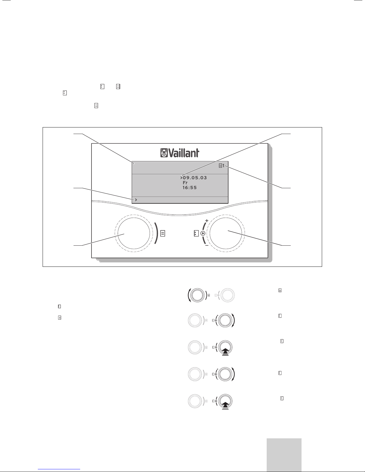
Fig. 5.1 Operating overview
Key
1 Menu name
2 Cursor indicates the selected parameter
3 menu number
4 Dial
5 Dial ,
6 Information line (in the example a handling request)
,
position parameter (turn), select parameter (press)
select menu (turn), activate special operation (press)
Time
Set day
2
3
4
Typical operating process (operator level)
• Turn the dial
to select the required menu.
• Turn the dial
to select the parameter to be
modified.
• Press the dial to mark the
parameter to be modified. The
parameter background is
darkened.
• Turn the dial to modify the
parameter setting value.
• Press the dial to mark the
setting value to be accepted.
GB
11Operating Manual geoTHERM VWS/VWW 0020051578_01
Page 14

5 Operation
5.2 Setting menus and parameters
setting to date modified setting
select menu:
Holiday programming
for cpl. System
Period of
time
1 >06.01.08 08.01.08
2 14.01.08 30.01.08
Room Temp. setpoint 12°C
>Set start day
Basic data
6
– Turn the dial: Select
menu e.g. from menu 6
to 7.
Select parameter:
7
Basic data
Date >21.04.08
Day of
week Mo
Time 09:35
>Set day
Basic data
7
7
Date >21.04.08
Day of
week Mo
Time 09:35
>Set day
Basic data
Date 21.04.08
Day of
week >Mon
Time 09:35
>Set weekday
• Turn the dial: select the
parameter to be modified,
e.g. from line 1 Day to line
2 Weekday (turn dial
through 3 further index
steps in this case).
Modify parameter weekday
7
from Monday to Tuesday:
– Push the dial:
Select parameter.
– Turn the dial:
Modify parameter.
– Push the dial:
Accept modification.
5.3 Description of the controller
The heating engineer will have set all the operating parameters to preset values during commissioning, so that
the heat pump can function optimally. However, you can
individually set and adapt the operating modes and
functions afterwards.
Date 21.04.08
Day of
week >Mon
Time 09:35
>Set weekday
Basic data
Date 21.04.08
Day of
week >Tues
Time 09:35
>Set weekday
7
5.3.1 Possible system circuits
The controller can control the following system circuits:
– a heating circuit.
– an indirectly heated hot water storage tank.
– a hot water circulation pump.
– a buffer circuit.
In order to extend the system a buffer circuit can be
used to connect up to six additional mixer circuit modules VR 60 (accessories) each with two mixer circuits.
The controller on the operating panel of the heat pump
is used to programme the mixer circuits.
In order to operate under comfortable conditions you
can connect the remote control units VR 90 for the first
eight heating circuits.
Operating Manual geoTHERM VWS/VWW 0020051578_0112
Page 15

Operation 5
5.3.2 Energy balance controller
The energy balance controller is only applicable to hydraulics without buffer cylinder.
For economical and fault-free operation of a heat pump,
it is important to regiment the starting of the compressor. The start-up of the compressor is the point at which
the highest loading occurs. With the help of the energy
balance controller it is possible to minimise starts of the
heat pump without compromising the comfort of a
pleasant room atmosphere.
As with other weather-controlled heating controllers the
controller determines a supply set target temperature
by capturing the outside temperature through a heating
curve. The energy balance calculation is carried out
based on this supply set target temperature and the
supply real temperature the difference of which is
measured per minute and added up:
1 degree minute [°min] = 1 K temperature difference in
the supply from 1 Minute (K = Kelvin)
The heat pump starts up at a defined heat deficit and
only switches off again when the supplied heat is equal
to the heat deficit.
The larger the preset negative numerical value is, the
longer the periods for which the compressor is kept
running or at standstill.
5.3.3 Charging principle buffer cylinder
The buffer cylinder is controlled depending on the setpoint flow temperature. The heat pump heats when the
temperature of the buffer cylinder head temperature
sensor VF1 is smaller than the set target temperature. It
heats until the temperature measured by the sensor at
the base of the buffer cylinder, RF1, has reached the setpoint temperature plus 2 K.
In the connection to a hot water cylinder charging the
buffer cylinder is also charged when the temperature of
the head temperature sensor VF1 is less than 2 K higher
than the set target temperature (premature reheating):
VF1 < T VL set + 2 K.
5.3.4 Resetting to factory settings
Caution!
Inadvertent deletion of specific settings!
a
When you reset the control system to
the default settings, specific system
settings can be deleted and the system
can shut down. The system does not
suffer damage.
After that you can select whether to reset only the
timer programme or all values to the default settings.
5.3.4 Controller structure
The top level display is a graphics display. It is the
starting point for all the available displays. This display
reappears automatically if you do not actuate any of the
dials for a long time when setting values.
Controller operation is subdivided into four levels:
The operator level is specified for the operator.
In Sect. 5.4 all of the controller's displays are shown as
a flow diagram. A detailed description of the displays is
contained in Sect. 5.5.
The code level (menu C1 - C9, D1 - D5, I1 - I5 and A1 - A9)
is reserved for the engineer and protected by a code to
protect it from unintentional modification.
As the operator you can scroll through the menus of the
code level and view the system-specific setting parameters however without changing the values.
In the menus C1 to C9 the engineer sets system-specific
parameters.
The menus D1 to D5 enable the engineer to operate and
test the heat pump in the diagnosis mode.
In Menus I1 to I5 you can obtain general information regarding the settings for the heat pump.
Menus A1 to A9 take the engineer through the installation menu to put the heat pump into operation.
The display and selection of special function
(e.g. the energy-saving function) is also possible for the
operator. Instructions on how to activate the special
functions are given in Chap. 5.6.
The fourth level contains functions for the optimisation
of the system and can only be set by the engineer using
vrDIALOG 810/2.
5.3.5 Adjusting the energy saving functions
Also described in Chap. 5.5 are heat pump settings that
will enable a reduction in your energy costs. This can be
achieved by finding the optimum setting of the heat
pump's weather-controlled energy balance controller.
This symbol points you to these energy saving tips.
• Press both dials simultaneously for at least 5 seconds
in the top-level display of the graphics display.
GB
13Operating Manual geoTHERM VWS/VWW 0020051578_01
Page 16
5 Operation
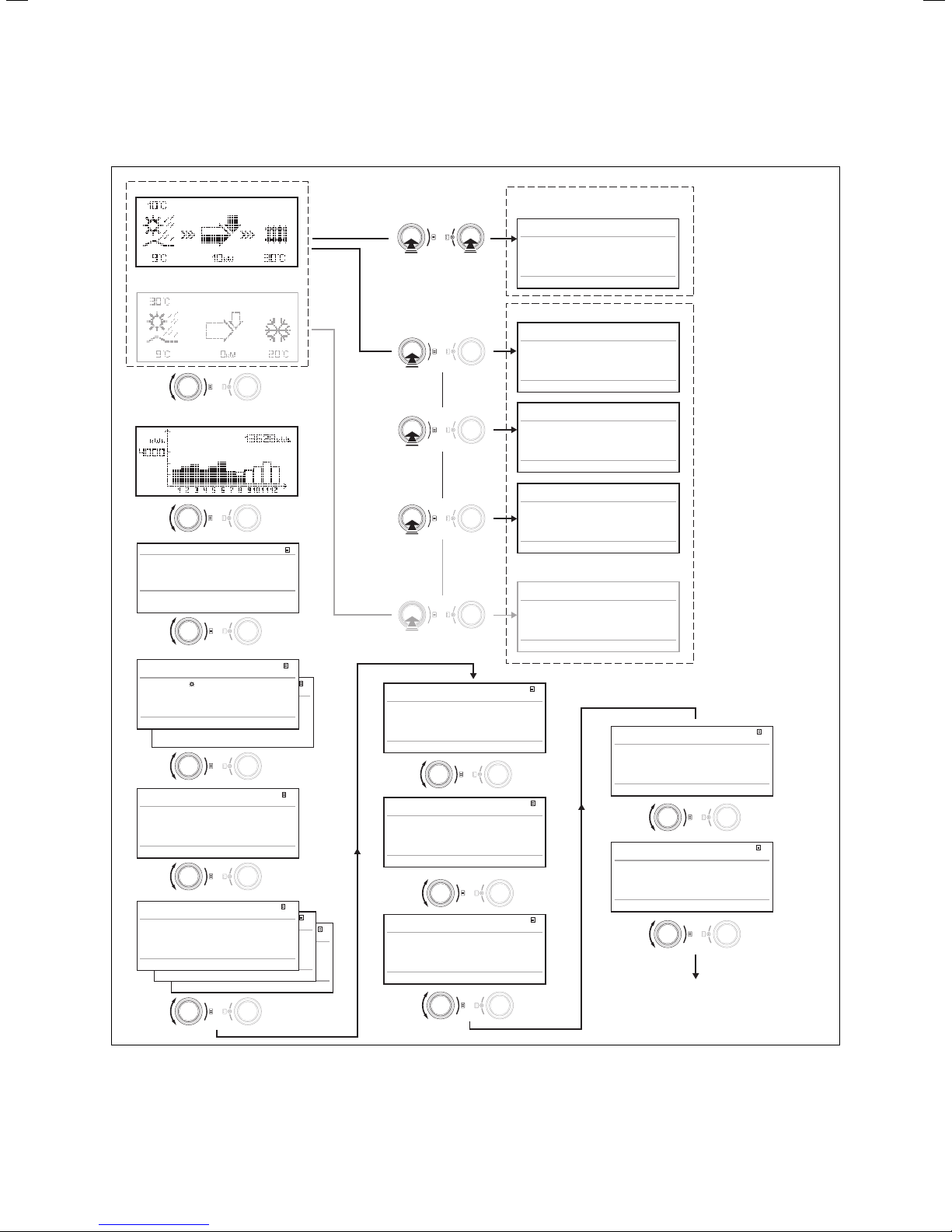
5.4 Flow diagram
Graphics display
Graphics display cooling*
Energy input display
Mo 21.04.08
Flow Temp. CH
System pressure 1,2bar
Brine pressure
CH : Comp only
Warning message
Warning message
16:49
28ºC
1,4bar
Reset to default
settings
We 16.02.08 9:35
> 5 sec.
Factory setting
Cancel
Time programme
Everything
> Select
NO/YES
NO/YES
NO/YES
Installer Menu
We 16.02.08 9:35
Sparen aktiviert for > 12:00
> Select stop time
We 16.02.08 9:35
Party function enabled
We 16.02.08 9:35
One-time
DHW tank loading enabled
1
Cooling settings *
We 16.02.08 9:35
Cooling function active for >3days
HK2
Parameters
HK2
Heating mode
Parameter
>Auto
Betriebsart Heizen
Set value day
>Auto
Night set back temp.
Raumsolltemp.
>Select operation mode
Night set back temp.
Domestic hot water
Parameters
Operation mode DHW > Auto
Max. DHW temp.
Min. DHW temp.
Current DHW temp.
>Select operation mode
HK2
Time programme
HK2
Time programme
>Mo
HK2
1 00:00 24:00
Time programme
>Mo
2 : :
1 00:00 24:00
>Mo
3 : :
2 : :
1 00:00 24:00
3 : :
>Select day of the week
2 : :
3 : :
>Select day of the week
>Select day of the week
20 ºC
15 ºC
60 ºC
44 ºC
51 ºC
2
20 ºC
15 ºC
4
5
2
5
5
Domestic hot water
Time programme
>Mo
1 06:00 22:00
2 : :
3 : :
>Select day of the week
Circulation pump
Time programme
>Mo
1 06:00 22:00
2 : :
3 : :
>Select day of the week
Holiday programming
for cpl. System
Periods
1 >06.01.08 08.01.08
2 14.01.08 31.01.08
Room Temp. setpoint
>Set starting day
Fig. 5.2 Displays at the user level
*) displays in grey may vary depending on the hydraulic plan set
> Set duration
5
5
6
12 ºC
Basic data 7
Date 21.04.08
Day of week > Mo
Time 09:35
> Set day of the week
Code layer 8
Code-Nummer:
> 0 0 0 0
Standard code:
1 0 0 0
>Adjust numeric character
Code level only for
expert technicians
Operating Manual geoTHERM VWS/VWW 0020051578_0114
Page 17
5.5 Displays at user level
The individual displays on the operator control panel are
described and explained below.
Display shown Description
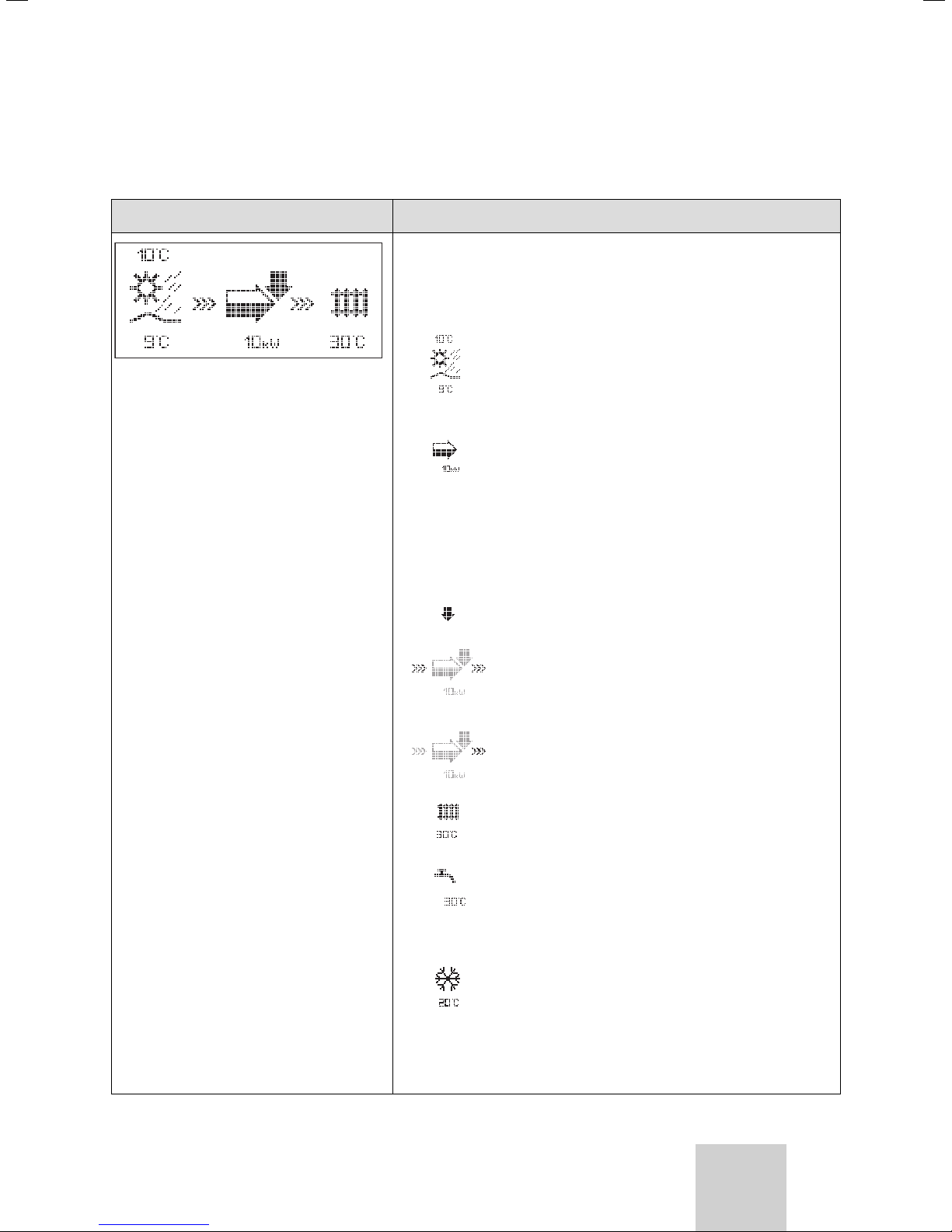
Graphics display (Top-level display)
You can read off the instantaneous state of the system from this display. This is always shown if you have not actuated either of the dials
for a long time while another display is showing.
Operation 5
Outside temperature (here 10 °C)
Source inlet temperature: Temperature sensor;
in the example 9 °C
Under the arrow the output of the heat source
(in the example 10 KW) is displayed.
The extent of darkening of the arrow graphically
shows the energy efficiency of the heat pump
under the given operating conditions.
The output of the heat source must not be
equated with the heating output.
The heating output corresponds to approx. the
output of the heat source + compressor output.
When the compressor or the electric auxiliary
heating is switched on, the arrow is shown filled.
>>> Left and right flash when the compressor is
switched on and energy is consequently being
taken from the environment and fed to the heating system.
>>> Right flashes when energy is being fed to the
heating system (e.g. only from the electric auxiliary heating).
The heat pump is in the CH mode. The heating
flow temperature is also displayed (30 °C shown
in example).
The symbol indicates that the domestic hot
water cylinder is being heated or that the heat
pump is in the ready state. The temperature in
the domestic hot water cylinder is also displayed.
Only if cooling is installed and the corresponding
settings have been made by the expert technician at the heat pump controller:
The symbol indicates that the heat pump is in
cooling operation. Under the symbol the actual
heating flow temperature is displayed
(in the example 20 °C).
Table 5.1 Settable parameters in the operator level
GB
15Operating Manual geoTHERM VWS/VWW 0020051578_01
Page 18
5 Operation
Display shown Description
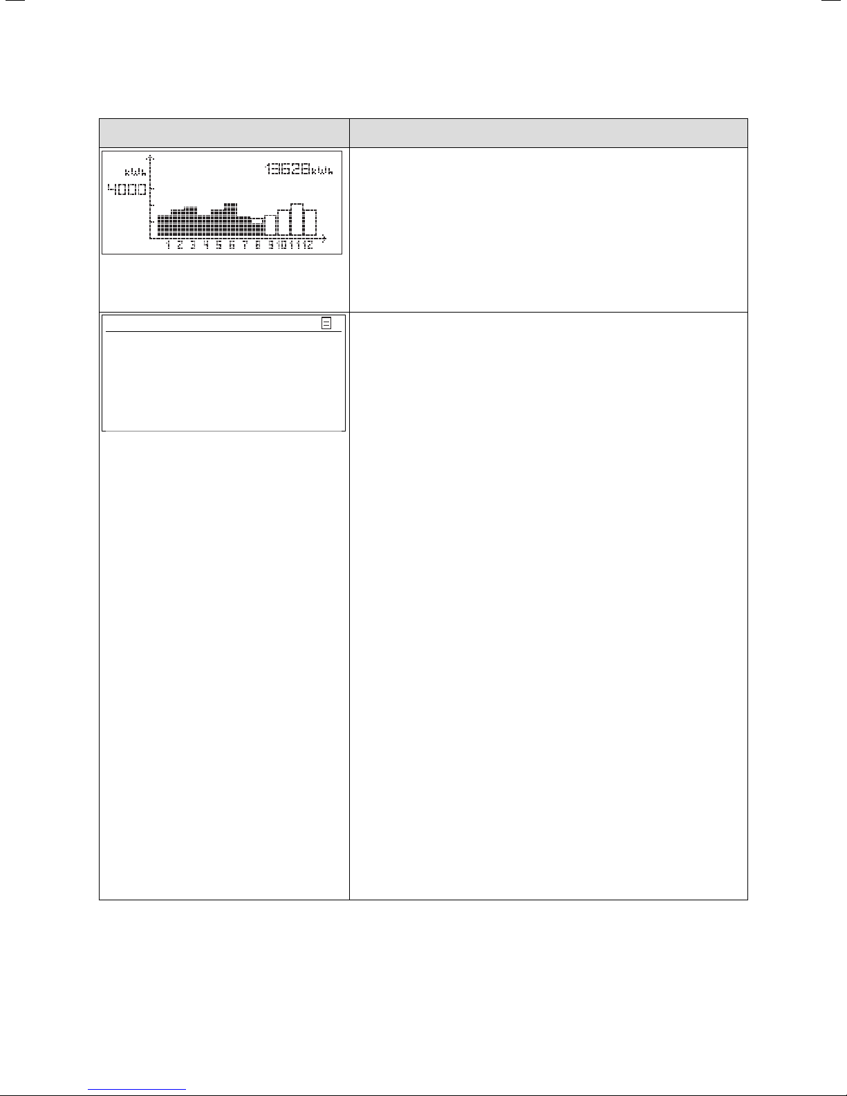
Energy input display
Shows the energy extracted from the environment for each of the
12 months of the current year (black bar). White-filled bars represent
the future months of the year; the height of the bar corresponds to
the yield for the month in the previous year (comparison possible).
On commissioning, the height of the bars is zero for all months, as no
information is available yet.
The scaling (in the example, 4000 kWh) adapts automatically to the
month's highest value.
Top right the total of the environmental yield since commissioning is
displayed (in the example: 13628 kWh).
Mon. 21.04.08 16:49 1
Current flow temp. 28 °C
CH pressure 1.2 bar
Brine pressure 1.4 bar
Heating only comp.
Warning message
Warning message
Day, date, time as well as flow temperature, heating system pressure
and heat source pressure are displayed.
Current flow temp: Current flow temperature in the unit.
Heating system pressure: Pressure sensor heating circuit.
Pressure heat source: Heat source pressure (Pressure sensor for
heat source circuit; brine pressure)
Heating only comp.: this status message provides information on the
current operating status. The following are possible:
Heating only comp.
Heating comp & ZH
CH: ZH only
CH:Comp&aux off
WW:Comp&aux off
WW: Comp only
WW: ZH only
Peak Rate: WW
Peak Rate: Stand-by
Acceleration mode
Frost prot. Heating
Frost prot. Cylind.
Legionella protect.
Automatic pump spin
Floor drying
Venting mode
Fault shutdown: heating
Error shutdown: heating
Fault shutdown: DHW
Error shutdown: DHW
Malfunction
Blocking error
Operation interlock
CH Comp overrun
WW Comp overrun
Cooling & WW
CH return too high
Table 5.1 Settable parameters in the operator level (contd.)
Under critical operating conditions a warning message is displayed in
both lower display lines. These lines are empty when the operating
conditions are normal.
Operating Manual geoTHERM VWS/VWW 0020051578_0116
Page 19
Operation 5
Display shown Description Factory setting
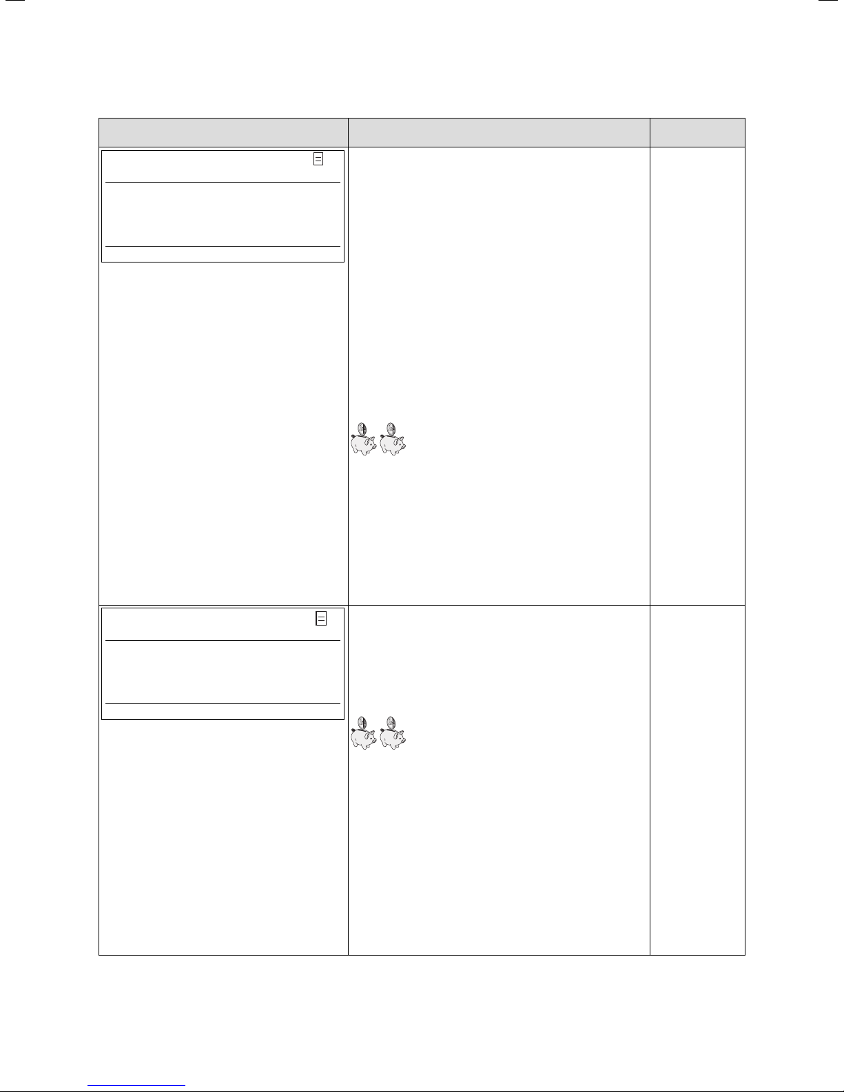
<HK2>
Parameters
Operating mode heating
>Auto
Set value day 22 °C
Night set back temp. 15 °C
>Select operating mode
The room set target temperature is the tempera-
2
ture to which the heating should be regulated in the
operating mode "Heat" or during the time slots.
Note: Select a room temperature that is just high
enough to ensure your personal well-being
(e.g. 20 °C). Each degree over and above the set
value means an increase in energy consumption of
around 6 % per annum.
The set-back temperature is the temperature to
which the heating is regulated during the set-back
period. An individual set-back temperature can be
set for each heating circuit.
The set operating mode determines under which
conditions the assigned heating circuit or hot water
circuit should be regulated.
Room set target
temp.: 20 °C
Set-back temp.:
15 °C
The following operating modes are available for
heating circuits:
Auto: The operation of the heating circuits alternates between the Heating and Energy Saving
operating modes in accordance with a settable timer
programme.
Eco: The operation of the heating circuits alternates
between the Heating and Off operating modes in
accordance with a settable timer programme. The
heating circuit is switched off during the set-back
period provided the frost protection function
(which depends on the outside
temperature) is not activated.
Heating: The heating circuit operates at the room
set target temperature regardless of any settable
timer programme.
Energy sav: The heating circuit operates at the setback temperature regardless of any settable timer
programme.
Off: The heating circuit is off, provided that the frost
protection function (depending on the external temperature) is not activated.
Note:
Additional heating circuits are displayed, depending
on the system configuration.
Table 5.1 Settable parameters in the operator level (contd.)
GB
17Operating Manual geoTHERM VWS/VWW 0020051578_01
Page 20
5 Operation
Display shown Description Factory setting
DHW loading
Parameters
Operating mode WW Auto
Max. DHW temp. 60 °C
Min. DHW temp. 44 °C
Cylinder temp. REAL
>Select set target temperature
51 °C
For connected domestic hot water cylinders and the
4
circulation circuit the operating modes Auto, On and
Off are possible.
The maximum WW temperature determines the
temperature to which the domestic hot water cylinder should be heated.
The minimum WW temperature determines the
limit below which the domestic hot water cylinder is
heated.
Note: The maximum WW temperature is only displayed when the auxiliary hot water heating is enabled.
Without electric auxiliary heating, the WW temperature is limited by the pressure sensor control shutoff in the cooling circuit and cannot be adjusted!
Cylinder temp. REAL: Current temperature in the
domestic hot water cylinder.
We recommend that hot water generation be
achieved without the electric auxiliary heating. by
this method, the maximum WW temperature is determined by the high pressure cut-out in the heat
pump cooling circuit. This cut-out corresponds to a
maximum hot water temperature of 58 °C. In order
to keep the heat pump starts to an absolute minimum as low a min. hot water temperature as possible should be selected.
Min. hot water
temp. 44 °C
You can set the heating times for each heating cir-
<HK2>
Time programme
>Mon
1 00:00 24:00
2: :
3: :
>Select weekday/block
5
cuit in the "HK2-Timer programme"
menu.
Up to three heating times can be programmed per
day or block. The control system operates according
to the heating curve and the room setpoint temperature.
The set back times can be dispensed with, depending
on the tariff agreement with power company (VNB)
or the construction of the house.
Power companies offer their own discounted tariffs
for heat pumps. It can make sense on economic
grounds to make use of the more favourable offpeak power.
In low-energy houses (in Germany standard as from
1st February 2002 energy conservation regulation)
the room temperature reduction can be dispensed
with owing to low heat losses.
The desired set-back temperature must be set in
menu 2.
Table 5.1 Settable parameters in the operator level (contd.)
Mon – Sun
0:00 – 24:00
Operating Manual geoTHERM VWS/VWW 0020051578_0118
Page 21
Operation 5
Display shown Description Factory setting
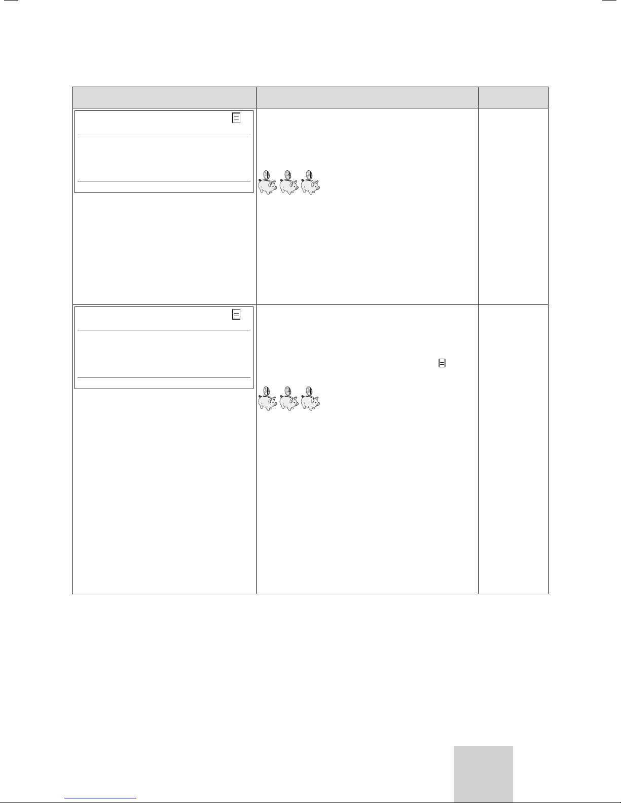
DHW loading
Time programme
>Mon
1 06:00 22:00
2: :
3: :
>Select weekday/block
You can set the times at which the domestic hot
5
water cylinder is heated in the "WW Timer Programme" menu.
Up to three times can be programmed per day or
block.
The hot water generation should only be active at
times when really hot water is to be run. Please set
this timer programme to your minimum requirements.
As an example, for working people a window from
6.00 – 8.00 hrs. and a second window from 17.00 –
23.00 hrs.can minimise the energy consumption due
to hot water generation.
Mon – Fri
6:00 – 22:00 hrs.
Sat
7:30 – 23:30
Su.
7:30 – 22:00
You can set the times at which the circulation pump
Circulation pump
Time programme
>Mon
1 06:00 22:00
2: :
3: :
>Select weekday/block
5
is to be operational in the "Circulation Pump Timer
Programme" menu.
Up to three times can be programmed per day or
block.
If the hot water operating mode (see menu
set to "ON", the circulation pump runs continuously.
The timer programme circulation pump should correspond to the
timer programme hot water, if necessary the time
slots could be selected even more restrictively.
If the desired hot water temperature is obtained
quickly enough without switching on the circulation
pump, the circulation pump can likewise be deactivated.
In addition, you can briefly activate the circulation
pump by means of electronic pushbutton switches
mounted in the immediate vicinity of the taps and
connected to the heat pump (the same idea as stairwell lighting). The operating times of the circulation
pump can thus be optimally matched to the actual
need.
Consult your expert technician about doing this.
Table 5.1 Settable parameters in the operator level (contd.)
3) is
Mon – Fri
6:00 – 22:00 hrs.
Sat
7:30 – 23:30
Su.
7:30 – 22:00
GB
19Operating Manual geoTHERM VWS/VWW 0020051578_01
Page 22

5 Operation
Display shown Description Factory setting
Holiday programming
for cpl. System
Period of
time
1 >06.01.08 08.01.08
2 14.01.08 30.01.08
Room Temp. setpoint 12 °C
>Set start day
For the controller and its connected system compo-
6
nents it is possible to programme two holiday periods with the introduction of the date. Moreover, the
desired target room temperature can be set for holidays, i.e. regardless of the preset timer programme.
After the holiday time has elapsed, the controller
automatically goes back to the previously selected
operating mode. The holiday program can be activated only in auto and eco operating mode.
Connected cylinder charging circuits or circulation
pump circuits are automatically switched to OFF
operating mode during the holiday time program.
Connected cylinder charging circuits or circulation
pump circuits are automatically switched to OFF
operating mode during the holiday time program.
Prolonged periods of absence can be set in the display "Programme holidays". The target temperature
during this period should be selected to be as low as
possible.
During this period hot water generation is not in
operation.
Period 1:
01.01.2003 –
01.01.2003
Period 2:
01.01.2003 –
01.01.2003
Room Temp. setpoint 15 °C
You can set the current date, the day of the week
Basic data
Date 21.04.08
Day of
week
Time 09:35
>Settable values
Code layer
Code number:
Mo
>0 0 0 0
7
and the current time, if DCF radio clock reception is
not possible, in the "Basic Data" menu.
These settings apply to all connected system components.
To access the Code level (Installer level), the appro-
8
priate code must be entered.
To view setting parameters without entering the
code, you must press the dial
view all parameters of the code level by turning
the dial
entering the code, you can view all menus in the
>Set figures
code level however not modify them.
Caution! Do not try to access the code level by
making arbitrary entries in the code level. Unintentional modification of the system-specific parameters can cause malfunctions or damage to the heat
pump.
Table 5.1 Settable parameters in the operator level (contd.)
once. You can then
but not change them. As operator, without
Operating Manual geoTHERM VWS/VWW 0020051578_0120
Page 23

5.6 Installer Menu
Special functions can be selected only from the basic
display. To do so press the left-hand dial
To change the parameter, you must turn the
.
dial. The
following special functions can be selected:
Operation 5
• Energy saving function: Press
• Party function: Press
dial twice.
• One-time charging: Press
• Cooling operation: Press
dial once.
dial 3 x.
dial 4 x
To activate one of the functions, you merely have to select it. In the energy saving function it is additionally
necessary to enter the time until which the energy saving function (regulation to set-back temperature) is to
apply.
The basic display appears either after the function has
elapsed (reaching the time) or by pressing the dial
again.
Display shown Description
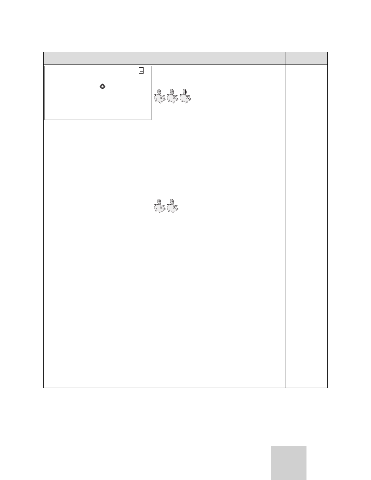
We 16.02.08 9:35
Saving function:
With the saving function you can set back the heating times for a
Energy saving enabled
settable period.
Enter the time for the end of the saving function in the format hh:mm
(hour:minute).
>Select end time
We 16.02.08 9:35
Party function enabled
Party function:
With the party function you can set the heating and hot water times
beyond the next switch off time on to the next start of heating. The
party function can only be used for the heating circuits or hot water
circuits for which the operating mode "Auto" or "ECO" is set.
We 16.02.08 9:35
one-time
DHW tank loading enabled
Table 5.2 Special functions
One-time charging:
This function allows you to charge the hot water cylinder once,
regardless of the current time program.
GB
21Operating Manual geoTHERM VWS/VWW 0020051578_01
Page 24

5 Operation
Display shown Description
We 16.02.08 9:35
Only if cooling is installed and the corresponding settings have been
made by the expert technician at the heat pump controller:
Cooling function active for > 3 days
Cooling duration: OFF/1 to 99 days.
If the cooling operation is active,
– the symbol of an ice crystal appears in the graphic display.
Table 5.2 Special functions (contd.)
• Reset to default setting: Keep dial and dial
pressed for longer than 5 seconds. After that you can
select whether to reset only the timer programme or
all values to the default settings.
Display shown Description
We 21.04.08 9:35
Factory setting
cancel NO/YES
Time programme NO/YES
Everything NO/YES
>Settable values
The default settings will be reinstated.
Caution! Ensure that a qualified technician performs the default setting reset. The system-specific settings are reset. The system can be
shut down. The system does not suffer damage.
Press the two dials for at least 5 seconds to call up the default settings menu.
Table 5.3 Reinstating default settings
Operating Manual geoTHERM VWS/VWW 0020051578_0122
Page 25

Operation 5
5.7 Starting up the heat pump
The start-up of your heat pump was carried out after
installation by your expert technician company.
Your heat pump does not need to be started up again if
it disconnects from the mains unexpectedly, for example
as a result of a voltage drop (power cut, circuit breaker
defective, circuit breaker deactivated). Your geoTHERM
heat pump has an automatic reset function, i.e. the heat
pump reverts automatically to its starting condition,
provided no fault is present in the heat pump itself. Find
out what to do in the event of a fault in Chap. 5.12.
5.8 Shutting down the heat pump
The heat pump can only be switched off via the operator control panel by deactivating the heating and hot
water generation (operating mode "Off").
<HK2>
Parameters
Operating mode heating
>Off
Set value day 22 °C
Night set back temp. 15 °C
>Select operating mode
Fig. 5.3 Switching off the heating mode
DHW loading
Parameters
Operating mode WW >Off
Max. DHW temp. 60 °C 60 °C
Min. DHW temp. 44 °C 44 °C
Cylinder temp. REAL
>Select set target temperature
Fig. 5.4 Switching off the hot water generation
Deactivate the fuse on your heating sys-
tem if you need to de-energise the heat
h
pump installation completely.
51 °C 51 °C
2
4
5.9 Inspection by a specialist engineer
In contrast to heaters based on fossil fuels, no expensive maintenance work is necessary for the Vaillant geoTHERM heat pump. However an annual inspection of the
system by a specialist is a prerequisite for continued
operational safety, reliability and a long working life.
Danger!
If inspections are not carried out, this
d
h
5.10 Inspection by the operator
In addition to the annual inspection by an expert, a
small amount of inspection work needs to be carried out
by the operator.
5.10.1 Checking the filling pressure of the heating
The filling pressure of the heating installation should be
checked at regular intervals.
Mon. 21.04.08 16:49 1
Current flow temp. 28 °C
CH pressure 1.2 bar
Brine pressure 1.4 bar
Heating only comp.
Warning message
Warning message
Fig. 5.5 Check filling pressure
• Read off the filling pressure of your heating installation at the heat pump controller (see Fig. 5.5).
The pressure in the heating installation should be between 1 and 2 bar. If it falls below 0.5 bar, the heat pump
will be shut down automatically and an error message
will be displayed.
can result in damage to property and
personal injury.
Only have inspections and repairs carried out by an approved heating installation company.
Note Have your system checked regular-
ly by an expert technician company to
ensure efficient operation of your heat
pump.
system
GB
23Operating Manual geoTHERM VWS/VWW 0020051578_01
Page 26

5 Operation
Caution!
Risk of damage from water escaping due
a
h
5.10.2 Checking the filling level and filling pressure
Check the brine level or pressure in the brine circuit at
regular intervals.
• Read off the filling pressure of the brine circuit ("pressure, heat source") at the heat pump controller (see
Fig. 5.5).
The brine filling pressure should be between 1 and 2 bar.
If it falls below 0.6 bar for 2 minutes, or falls below
0.2 bar once, the heat pump is automatically switched
off and an error message is displayed
(see Chap. 3.3 "Low brine pressure protection").
to leaks in the system.
Close the cold water stop valve in the
event of leaks in the hot water pipework.
De-energise the heat pump if the heating
installation is leaking (fuse off).
Have the leaks repaired by an expert
technician.
Note
The cold water stop valve is not included
in the scope of delivery for the heat
pump. It is fitted on site by your heating
engineer. He will explain the location and
handling of the component to you.
of the brine circuit
If the filling level of the brine has fallen so far that it is
no longer visible in the expansion tank, you must have
the brine replenished.
12
Fig. 5.6 Filling level of the brine expansion tank
Key to Fig. 5.5
1 Filling level too low
2 Filling level correct
It is normal for the filling level of the brine to fall a little
in the first month after the start-up of the system. The
filling level can also vary depending on the temperature
of the heat source. However it should never sink so far
that it is no longer visible in the expansion tank.
a
a
Caution!
Risk of damage due to brine escaping
from leaks in the system.
De-energise the heat pump if the brine
circuit is leaking (fuse off).
Have the leaks repaired by an expert
technician.
Caution!
Risk of damage.
The brine circuit must be filled with
the correct quantity of fluid; otherwise
the system can be damaged. Check the
filling level of the brine circuit at regular
intervals and inform your expert technician company if the filling level in the
brine expansion tank is too low. The
filling of the brine circuit in your heat
pump installation may only be undertaken by authorised specialists.
5.11 Cleaning and care
Do not use any scouring or cleaning agents that could
damage the cladding.
Note
Clean the exterior of your heat pump
h
with a damp cloth and a little soap.
Operating Manual geoTHERM VWS/VWW 0020051578_0124
Page 27

Operation 5
5.12 Troubleshooting and diagnosis
5.12.1 Error messages on the controller
Error messages appear roughly 20 seconds after the
error has occurred in the display and are written in the
error memory of the controller if the error persists for
roughly 3 minutes. The engineer can then call up the
error message from the memory at a later date.
Error History
Fault number >1
Fault code 41
16.02.08 07:18
Error CH circuit
Sensor T3 heat source
Fig. 5.7 Error message in the error memory Menu I1
The geoTHERM control system has various malfunction
types:
– Malfunction of components which are connected via
eBUS.
– Temporary shutdown
The heat pump remains in operation. The error is displayed and disappears independently when the cause
of the fault is removed.
– Fault-induced shutdown
The heat pump is shut down. It can only be restarted
after the cause of the fault has been removed by the
expert technician and the error reset.
– Moreover, other errors/malfunctions can occur on
the unit or system.
I1
5.12.2 Activating emergency mode
Depending on the type of malfunction the expert technician can set the heat pump to continue operation in
emergency mode (via an integrated electric auxiliary
heating) until the cause of the error is remedied, and either for heating operation (display "heating priority"),
for hot water operation (display "hot water priority") or
for both (display "heating priority/hot water priority"),
see the following tables, column "emergency operation".
5.12.3 Errors/malfunctions that you can remedy
Malfunction sign Possible cause Solution
Noise in the heating
circuit.
Table 5.4 Other malfunctions
5.12.4 Warning messages
The following warning messages do not cause a malfunction in the operation of the heat pump. The heat
pump is not shut down.
Take note of the error code and text and discuss this
during the next inspection with the expert technician.
Fault code Error text/description
26 Overheating on compressor pressure side
36 Low brine pressure
Table 5.5 Warning messages, no shutdown
Dirt in the heating
circuit.
Faulty pump.
Air in the heating
circuit.
Bleeding heating
circuit.
a
h
Caution!
Heat pump malfunction!
Immediately notify your expert technician if error messages appear on the display on the operating panel which are
not listed in tables 5.4 to 5.7.
Do not attempt to remove the source of
the malfunction yourself.
Note!
Not all of the following listed malfunctions have to be dealt with by an expert
technician.
If you are unsure whether you can remedy the fault yourself or not or if the
error occurs repeatedly contact your
expert technician or Vaillant customer
service.
GB
25Operating Manual geoTHERM VWS/VWW 0020051578_01
Page 28

5 Operation
5.12.5 Temporary malfunctions
The heat pump is shut down temporarily and starts
up again independently when the cause of the fault is
removed.
Depending on the error the heat pump switches back on
automatically after 5 or 60 minutes.
Take note of the error code and text and discuss this
during the next inspection with the expert technician.
Fault code Error text/description
20 Frost protection heat source monitoring source
21
(only VWW)
22
(only VWS)
23
(only VWW)
27 Coolant pressure too high
28 Coolant pressure too low
29 Coolant pressure outside the range
outlet
Temperature difference of the heat source > set
value "permitted temp. difference"
This error message is deactivated as standard and
can only be activated via vrDIALOG parameter
"permitted temp. difference" (20 K difference
means deactivated).
Frost protection heat source over. source outlet
Source outlet temperature too low (<4 ºC)
Frost protection heat source over. source outlet
Source outlet temperature too low
(<parameter freezing protection in menu A4)
No ground water flow
Integrated flow switch does not detect any volume
flow
The integrated high pressure switch tripped at
30 bar (g).
The heat pump cannot be restarted until after
60 min. at the earliest.
The integrated low pressure switch tripped at
1.25 bar (g).
If the error occurs twice in a row the heat pump
cannot be started until after 60 min. at the earliest.
5.12.6 Blocking error
Errors could occur which result in the shutdown of the
heat pump.
Fault code Error text/description
32 Error heat source sensor T8
Short-circuit in the sensor
33 Error heat circuit pressure sensor
short-circuit in the pressure sensor
34 Error brine pressure sensor
short-circuit in the pressure sensor
40 Error comp outlet sensor T1
Short-circuit in the sensor
41 Error heat source sensor T3
Short-circuit in the sensor
42 Error HP return sensor T5
Short-circuit in the sensor
43 Error HP flow sensor T6
Short-circuit in the sensor
44 Error external sensor AF
Short-circuit in the sensor
45 Error DHW tank sensor SP
Short-circuit in the sensor
46 Error HB flow sensor VF1
Short-circuit in the sensor
47 Error HB return sensor RF1
Short-circuit in the sensor
48 Error flow sensor VF2
Short-circuit in the sensor
Emergency
mode
possible
possible
possible
possible
possible
possible
possible
possible
possible
possible
WW operation
possible
Table 5.6 Temporary malfunctions
52 Sensors are not suited to the hydrau-
60 Frost protection heat source moni-
61
only VWW
62
only VWS
Table 5.7 Error shutdown
lic plan
toring source outlet
Error 20 has occurred three times
in a row
Frost protection heat source monitoring source outlet
Error 21 has occurred three times in
a row
Frost protection heat source monitoring source outlet
Error 22 has occurred three times in
a row
Operating Manual geoTHERM VWS/VWW 0020051578_0126
_
possible
possible
possible
Page 29

Operation 5
Warranty and customer service 6
Fault
code
63
only
VWW
72 Flow temperature too high for under-
81 Coolant pressure too high
83 Coolant pressure too low. Check heat
84 Coolant pressure outside the range
90 Heating system pressure too low
Table 5.7 Fault-induced shutdown (contd.)
Error text/description
No ground water flow
Error 23 has occurred three times in a
row
floor heating
Flow temperature is for 15 min. higher
than a set value (max. HK temp. +
compr. hysteresis + 2 K).
Error 27 has occurred three times in a
row
source
Error 28 has occurred three times in a
row
Error 29 has occurred three times in a
row
Pressure <0.5 bar
Heat pump shuts down and goes into
operation automatically when the pressure rises above 0.7 bar
Emergency
mode
possible
_
possible
possible
possible
_
date the warranty (this does not affect the customer’s
statutory rights).
6.3 Vaillant Service
To ensure regular servicing, it is strongly recommended
that arrangements are made for a Maintenance
Agreement. Please contact Vaillant Service Solutions
(0870 6060 777) for further details.
• Consult your expert technician about doing this.
Note!
Only an expert technician can remedy
h
the fault and reset the error code.
Once the expert technician has remedied the error and
reset the error he can restart the heat pump.
6 Warranty and customer service
6.1 Vaillant warranty
Vaillant provide a full parts and labour warranty for this
appliance.
The appliance must be installed by a suitably competent
person in accordance with the Gas Safety
(Installation and Use) Regulations 1998, and the manufacturer’s instructions. In the UK ‘CORGI’ registered installers undertake the work in compliance with safe and
satisfactory standards.
All unvented domestic hot water cylinders must be installed by a competent person to the prevailing building
regulations at the time of installation (G3).
Terms and conditions apply to the warranty, details of
which can be found on the warranty registration card included with this appliance.
Failure to install and commission this appliance in compliance with the manufacturer’s instructions may invali-
GB
27Operating Manual geoTHERM VWS/VWW 0020051578_01
Page 30

7 Appendix
7 Appendix
7.1 Technical Data VWS
Description Unit VWS 220/2 VWS 300/2 VWS 380/2 VWS 460/2
Article number - 0010002797 0010002798 0010002799 0010002800
Height without connections
Width
Depth without pillars
Depth with pillars
Weight
- with packaging
- without packaging
- ready for operation
Rated voltage
- Compressor
- Brine pump
- Heating circuit pump
- Control circuit
- External auxiliary heating
Fuse, slow-blow A 20 25 32 40
Start-up current
- without start-up current limiter
- with start-up current limiter
Electrical power consumption/rated output
- min. for B-5W35
- max. for B20W60
- phase angle, cos phi
- external auxiliary heating
EN 60529 level of protection - IP 20
Hydraulic connections
- Heating circuit flow and return
- Heat source flow and return
Heat source circuit (brine circuit)
- Brine type
- max. operating pressure
- min. inlet temperature
- max. inlet temperature
- Nominal flow rate dT 3 K
- Residual head dT 3 K
- Nominal flow rate dT 4 K
- Residual head dT 4 K
- Electrical power consumption - pump
CH circuit
- max. operating pressure
- min. flow temperature
- max. flow temperature
- Nominal flow rate dT 5 K
- Pressure loss dT 5 K
- Nominal flow rate dT 10 K
- Pressure loss dT 10 K
- Electrical power consumption - pump
refrigerant circuit
- Coolant type
- Quantity kg 4.1 5.99 6.7 8.6
- Permissible operating overpressure
- Compressor type
- Oil
- Oil filling capacity
Table 7.1 Technical Data VWS
mm
mm
mm
mm
kg
kg
kg
-
A
A
kW
kW
kW
mm
mm
MPa (bar)
°C
°C
l/h
mbar
l/h
mbar
W
MPa (bar)
°C
°C
l/h
mbar
l/h
mbar
W
- R 407 C
MPa (bar)
-
l
356
326
341
1/N/PE 230 V 50 Hz 3/N/PE 400 V 50 Hz
99
44
4.9
10.0
0.7-0.84
4858
324
3644
468
390
3726
72
1902
23
4 4 4.14 4.14
370
340
359
1/N/PE 230 V 50 Hz (max. 1 x 2 A)
3/N/PE 400 V 50 Hz (max. 3 x 13 A)
127
65
6.6
12.0
0.72-0.83
6660
275
4995
439
390
5160
87
2580
25
1200
760
900
1100
394
364
386
3/N/PE 400 V 50 Hz
1/N/PE 230 V 50 Hz
167
85
8.5
16.0
0.76-0.86
3 x 3 (3 x 13 A)
G 1 1/2"
G 1 1/2"
Ethylene glycol 30 %
0.3 (3)
-10
20
8640
431
6480
655
585
0.3 (3)
25
62
6600
132
3336
40
2.9 (29)
Scroll
Ester
417
387
414
198
110
10.2
18.0
0.75-0.86
9840
379
7380
626
585
7680
173
3900
53
Operating Manual geoTHERM VWS/VWW 0020051578_0128
Page 31

Appendix 7
Description Unit VWS 220/2 VWS 300/2 VWS 380/2 VWS 460/2
Heat pump performance data
B0W35 dT5
- Heating output
- Power consumption
- Performance figure/COP
B0W35 dT10
- Heating output
- Power consumption
- Performance figure/COP
Performance data, heat pump (contd.)
B5W55
- Heating output
- Power consumption
- Performance figure/COP
Internal sound level dBA 63 63 63 65
Conforms to safety regulations - CE-1027 mark
Table 7.1 Technical data - VWS (contd.)
7.2 Technical Data VWW
kW
kW
-
kW
kW
-
-
kW
kW
-
21.6
5.1
4.3
22.1
4.9
4.5
23.0
7.0
3.3
29.9
6.8
4.4
30.5
6.5
4.7
31.5
9.6
3.3
Low Voltage Directive 73/23/EWG
EMC Directive 89/336/EWG
Pressure equipment directive 97/23/EC, category II
38.3
8.8
4.4
38.7
8.4
4.6
41.1
12.3
3.4
EN 60335
ISO 5149
45.9
10.6
4.4
45.5
10.1
4.5
48.6
14.7
3.3
Description Unit VWW 220/2 VWW 300/2 VWW 380/2 VWW 460/2
Article number - 0010002801 0010002802 0010002803 0010002804
Height without connections
Width
Depth without pillars
Depth with pillars
Weight
- with packaging
- without packaging
- ready for operation
Rated voltage
- Compressor
- External well pump
- External heating circuit pump
- Control circuit
- External auxiliary heating
Fuse, slow-blow A 20 25 32 40
Start-up current
- without start-up current limiter
- with start-up current limiter
Electrical power consumption/rated output
- min. for B-5W35
- max. for B20W60
- phase angle, cos phi
- external auxiliary heating
EN 60529 level of protection - IP 20
Table 7.2 Technical Data VWW
mm
mm
mm
mm
kg
kg
kg
-
A
A
kW
kW
kW
1200
760
900
1100
340
310
325
3/N/PE 400 V 50 Hz (max. 3 x 5 A) 3/N/PE 400 V 50 Hz (max. 3 x 8.5 A)
99
44
4.9
10.0
0.7-0.84
354
324
343
3/N/PE 400 V 50 Hz
1/N/PE 230 V 50 Hz (max. 1 x 2 A)
1/N/PE 230 V 50 Hz
3/N/PE 400 V 50 Hz (max. 3 x 13 A)
127
65
6.6
12.0
0.72-0.83
374
344
366
167
85
8.5
16.0
0.76-0.86
3 x 3 (3 x 13 A)
397
367
394
198
110
10.2
18.0
0.75-0.86
GB
29Operating Manual geoTHERM VWS/VWW 0020051578_01
Page 32

7 Appendix
Description Unit VWW 220/2 VWW 300/2 VWW 380/2 VWW 460/2
Hydraulic connections
- Heating circuit flow and return
- Heat source flow and return
Heat source circuit
- max. operating pressure
- min. inlet temperature
- max. inlet temperature
- Nominal flow rate dT 3 K
- Residual head dT 3 K
- Nominal flow rate dT 4 K
- Residual head dT 4 K
- Electrical power consumption - pump
CH circuit
- max. operating pressure
- min. flow temperature
- max. flow temperature
- Nominal flow rate dT 5 K
- Residual head dT 5 K
- Nominal flow rate dT 10 K
- Residual head dT 10 K
- Electrical power consumption - pump
refrigerant circuit
- Coolant type - R 407 C
- Quantity kg 4.3 5.99 6.7 8.6
- Permissible operating overpressure
- Compressor type
- Oil
- Oil filling capacity
Heat pump performance data
W10W35 dT5
- Heating output
- Power consumption
- Performance figure/COP
W10W35 dT10
- Heating output
- Power consumption
- Performance figure/COP
W10W55
- Heating output
- Power consumption
- Performance figure/COP
Internal sound level dBA 63 63 63 65
Conforms to safety regulations -
mm
mm
MPa (bar)
°C
°C
l/h
mbar
l/h
mbar
W
MPa (bar)
°C
°C
l/h
mbar
l/h
mbar
W
MPa (bar)
-
l
kW
kW
-
kW
kW
-
kW
kW
-
G 1 1/2"
G 1 1/2"
" - "
" - "
6417
" - "
4813
" - "
" - "
5099
106
2603
31
" - "
4 4 4.14 4.14
29.9
5.8
5.2
30.2
5.5
5.5
26.9
7.6
3.5
8760
" - "
6570
" - "
" - "
6960
152
3600
45
" - "
41.6
7.8
5.3
42.4
7.5
5.7
37.2
10.4
3.6
Low Voltage Directive 73/23/EWG
EMC Directive 89/336/EWG
Pressure equipment directive 97/23/EC, category II
" - "
10800
" - "
8100
" - "
" - "
0.3 (3)
25
62
8700
198
4500
58
" - "
2.9 (29)
Scroll
Ester
52.6
9.8
5.3
52.3
9.4
5.5
47.4
12.9
3.6
CE-1027 mark
EN 60335
ISO 5149
13080
" - "
9810
" - "
" - "
10440
251
5520
76
" - "
63.6
12.4
5.1
64.7
12.0
5.4
57.3
15.8
3.6
Tab. 7.2 Technical data - VWW (contd.)
Page 33

Appendix 7
7.3 Data badge
An identification plate is attached to the baseplate on
the inside of the geoTHERM heat pump. The type designation is on the front cladding at the top of the unit
(also see Fig. 3.3, Pos. 2).
Vaillant GmbH Remscheid / Germany
Serial-No. 21054500100027970006000001N1
VWS 220/2
IP 20
3/N/PE 400V 50Hz
1/N/PE 230V 50Hz
3/N/PE 400V 50Hz
10 kW
10 kW
-- kW
99 A
44 A
COP B0/W35
B5/W55
COP
B0/W35
B5/W55
21054500100028300006000001N4
Fig. 7.1 Example of an identification plate
< 44 A
R407 C
4,1 kg
2,9 (29) MPa (bar)
4,3
3,3
21,6 kW
23,0 kW
Explanation of the symbols on the identification
plate
Rated voltage - compressor
Measuring voltage, controller +
heating circuit pump
Rated voltage - auxiliary heating
Rated maximum power
Rated power - compressor, pumps
and controller
Rated power - auxiliary heating
Start-up current without start-up
current limiter
44 A
COP B0/W35
COP B5/W55
B0/W35
B5/W55
Start-up current with start-up
current limiter
Coolant type
Filling quantity
Permissible rated overpressure
Performance figure at a brine tem-
perature of 0 °C and a heating flow
temperature of 35 °C
Performance figure at a brine temperature of 5 °C and a heating flow
temperature of 55 °C
Heating output at a brine temperature of 0 °C and a heating flow
temperature of 35 °C
Heating output at a brine temperature of 5 °C and a heating flow
temperature of 55 °C
.1027 CE mark
VDE/GS mark
VDE-EMC mark
Read the Operating and Installation
Manual!
Humidity protection class
Ensure proper disposal at the end
of its useful life (not household
waste)
21054500100028300006000001N4
Serial Number
Table 7.3 Explanation of symbols
Page 34

Page 35

Para el usuario
Instrucciones de uso
geoTHERM
Bomba de calor
VWS/VWW
ES
Page 36

Índice
Índice
Generalidades ............................................................... 3
Placa de características ....................................................... 3
1 Observaciones sobre estas instrucciones ..... 3
1.1 Documentación de validez paralela ..................... 3
1.2 Conservación de la documentación ..................... 3
1.3 Símbolos utilizados ................................................... 4
1.4 Validez de las instrucciones ................................... 4
2 Indicaciones de seguridad ................................ 4
2.1 Refrigerante ............................................................... 4
2.2 Prohibición de realizar cambios ............................ 5
3 Descripción del aparato y su
funcionamiento .................................................. 5
3.1 Principio funcional .................................................... 5
3.2 Funcionamiento del circuito de refrigerante ..... 6
3.3 Funciones adicionales automáticas ...................... 6
3.4 Estructura de la bomba de calor ........................... 7
4 Indicaciones sobre la instalación y el uso ..... 8
4.1 Utilización adecuada ................................................ 8
4.2 Requisitos del lugar de instalación ....................... 9
4.3 Condensación ............................................................. 9
4.4 Consejos de ahorro energético ............................. 9
4.4.1 Consejos generales de ahorro energético .......... 9
4.4.2 Posibilidades de ahorro mediante un ajuste
adecuado de la regulación ...................................... 10
5.12.4 Advertencias .............................................................. 25
5.12.5 Averías temporales................................................... 26
5.12.6 Fallo desconexión...................................................... 26
6 Garantía y Servicio de atención al cliente .... 27
6.1 S.A.T. oficial ................................................................ 27
6.2 Garantía del Fabricante ........................................... 27
7 Anexo.................................................................. 28
7.1 Datos técnicos VWS ................................................. 28
7.2 Datos técnicos VWW ................................................ 29
7.3 Placa de características .......................................... 31
5 Uso ...................................................................... 11
5.1 Aprendizaje y utilización del regulador ............... 11
5.2 Ajustar los menús y parámetros ........................... 12
5.3 Descripción del regulador ....................................... 12
5.3.1 Posibles circuitos de la instalación ....................... 12
5.3.2 Regulación del equilibrio energético ................... 13
5.3.3 Principio de carga del acumulador intermedio . 13
5.3.4 Restablecimiento de los ajustes de fábrica ........ 13
5.3.4 Estructura del regulador ......................................... 13
5.3.5 Ajustar las funciones de ahorro energético ....... 13
5.4 Diagrama de operaciones ....................................... 14
5.5 Pantallas del nivel de usuario ................................ 15
5.6 Estado Menu Instal ................................................... 21
5.7 Puesta en marcha de la bomba de calor ............ 23
5.8 Puesta fuera de funcionamiento de la bomba
de calor ........................................................................ 23
5.9 Inspección por el personal experto ...................... 23
5.10 Inspección por el usuario ........................................ 23
5.10.1 Controlar la presión de llenado de la
instalación de calefacción ....................................... 23
5.10.2 Controlar el nivel y presión de llenado del
circuito de solución salina ...................................... 24
5.11 Limpieza y cuidados ................................................ 24
5.12 Eliminación de averías y diagnóstico ................... 25
5.12.1 Mensajes de error del regulador ........................... 25
5.12.2 Activar el servicio de emergencia ........................ 25
5.12.3 Errores/averías que puede solucionar usted .... 25
Instrucciones de uso geoTHERM VWS/VWW 0020051578_012
Page 37

N
Generalidades
Observaciones sobre estas instrucciones 1
Generalidades
Las bombas de calor geoTHERM de Vaillant se denominan en estas instrucciones generalmente bombas de
calor. Estas instrucciones de uso son válidas para las siguientes variantes:
Denominación de tipo Referencia
Bombas de calor de solución salina y agua
VWS 220/2 0010002797
VWS 300/2 0010002798
VWS 380/2 0010002799
VWS 460/2 0010002800
Bombas de calor de agua y agua
VWW 220/2 0010002801
VWW 300/2 0010002802
VWW 380/2 0010002803
VWW 460/2 0010002804
Tabla 0.1 Placa de características y referencias del artículo
Las bombas de calor han sido fabricadas
según las normas de seguridad técnica y los
últimos avances técnicos.
Su conformidad con las normas pertinentes ha
sido demostrada.
VDE y seguridad demostrada
Con el distintivo CE el fabricante del aparato certifica
que los aparatos de la serie geoTHERM cumplen los requisitos de las directivas de la UE sobre la compatibilidad electromagnética (directiva 89/336/CEE del Consejo). Los aparatos reúnen los requisitos fundamentales
de la directiva sobre bajo voltaje (directiva 73/23/CEE
del Consejo).
Asimismo, los aparatos cumplen los requisitos de la
norma EN 14511 (Bombas de calor con condensadores
eléctricos, calentadores, requisitos de aparatos para calefacción y agua caliente potable) así como la norma
EN 378 (Requisitos de seguridad técnicos y medioambientales de instalaciones de frío y bombas de calor).
Placa de características
En las bombas de calor geoTHERM se encuentra una
placa de características en la parte superior frontal de
la chapa eléctrica. En la parte superior del revestimiento
frontal hay una denominación de tipo (véase también
fig. 3.3, pos. 1). En el capítulo 7.3, Apéndice, se incluye
una imagen de la placa de características con los datos
técnicos y una tabla en la que se explican los símbolos
utilizados en dicha placa.
1 Observaciones sobre estas
instrucciones
Las presentes instrucciones contienen información importante para un manejo seguro y adecuado de su
bomba de calor.
1.1 Documentación de validez paralela
La documentación complementaria vigente se compone
de todas las instrucciones que describen el uso de la
bomba de calor así como las instrucciones de los demás
componentes auxiliares.
1.2 Conservación de la documentación
Conserve estas instrucciones de uso, así como el resto
de la documentación vigente, de modo que estén disponibles siempre que sea necesario.
Puede guardar la documentación dentro de la tapa de la
columna.
En caso de mudanza o venta, entregue la documentación al sucesor.
1
L
2
L
3
L
N
E
P
1
L
2
L
3
L
N
E
P
1
L
2
L
3
L
N
E
P
F
OTA
F
C
D
- +
AufZu
NL
HK2-P HK2 VF2 RF1 VF1 SP BUSDCF/AF EVU1xZPLP/UV 1
NL
SK2-P
NL
ZP
N NAufZuL N 1212121 21212
ZH
2 345SC
L LLL L1 LNNNN N 2 N21 21LN
1
678ASB
H
0
-3
8
A
B
B
A
1
-0
0
-3
8
A
B
B
A
1
-0
0
-3
12
A
B
B
A
1
-0
0
-3
12
A
B
B
A
1
-0
0
-3
12
A
B
B
A
1
-0
0
-3
8
A
B
B
A
1
-0
Fig. 1.1 Retirar la tapa de la columna
3Instrucciones de uso geoTHERM VWS/VWW 0020051578_01 ES
Page 38

1 Observaciones sobre estas instrucciones
2 Indicaciones de seguridad
1.3 Símbolos utilizados
En estas instrucciones se utilizan los siguientes símbolos para indicar los peligros, notas, acciones necesarias
y consejos para ahorrar energía.
¡Peligro!
¡Peligro de lesiones físicas y de muerte!
d
¡Peligro!
¡Peligro de escaldadura y de quemadu-
H
a
ras!
¡Atención!
Posible situación de riesgo para el producto y el medio ambiente.
Observación
Información útil e indicaciones.
h
Este símbolo indica un consejo para ahorrar energía.
Puede ahorrar energía, entre otras cosas, regulando la
bomba de calor.
• Símbolo que indica una actividad que debe realizarse.
1.4 Validez de las instrucciones
Estas instrucciones solo son válidas para las bombas de
calor con las denominaciones de tipo que aparecen en la
tabla 0.1.
2.1 Refrigerante
La bomba de calor se suministra con un nivel adecuado
de refrigerante R 407 C. Este refrigerante no contiene
cloro, por lo que no perjudica la capa de ozono. El refrigerante R 407 C no es combustible ni supone un peligro
de explosión.
¡Peligro!
¡Peligro para el medio ambiente!
a
d
Este aparato contiene refrigerante
R 407 C. Este producto no debe verterse
a la atmósfera. El refrigerante R 407 C
es un gas de invernadero fluorado sin
cloro reconocido por el Protocolo de
Kioto con GWP 1653 (GWP = Global
Warming Potential).
El refrigerante del aparato debe vaciarse
por completo antes de desechar el aparato utilizando contenedores apropiados
para reciclarlo o eliminarlo según las
normas vigentes.
Los trabajos relacionados con el refrigerante quedan exclusivamente reservados
al personal oficialmente cualificado.
¡Peligro!
Peligro de congelación por contacto con
el refrigerante R 407 C.
Si se toca el refrigerante presente en los
puntos de salida puede dar lugar a congelación:
En caso de fugas en el circuito del refrigerante, evite inhalar los gases y vapores.
Evitar el contacto con la piel y los ojos.
2 Indicaciones de seguridad
Tenga en cuenta las siguientes observaciones de seguridad y prescripciones cuando utilice la bomba de calor:
• Pida al técnico del S.A.T. oficial que le explique el funcionamiento de la bomba de calor.
• Lea atentamente estas instrucciones de uso.
• Lleve a cabo únicamente las acciones que se describen en estas instrucciones de uso.
¡Peligro!
Peligro de quemadura por contacto de
H
componentes de la bomba de calor.
Los componentes de la bomba de calor
pueden alcanzar temperaturas muy elevadas.
No toque los conductos no aislados de la
bomba de calor.
No retire ninguna parte del revestimiento (excepto la tapa de la columna, véase
Cap. 1.2).
h
Observación
En condiciones normales de uso, el refrigerante R 407 C no supone ningún riesgo. Sin embargo, su uso no adecuado
puede dar lugar a daños y lesiones.
Instrucciones de uso geoTHERM VWS/VWW 0020051578_014
Page 39

Indicaciones de seguridad 2
Descripción del aparato y su funcionamiento 3
En caso de que en esta instalación se haya instalado
una refrigeración externa pasiva:
¡Atención!
¡Peligro de no superar el punto de des-
a
a
2.2 Prohibición de realizar cambios
congelación y de formación de condensación!
La temperatura de ida de la calefacción
no debe ajustarse demasiado baja en el
servicio de refrigeración. Incluso con una
temperatura de ida de 20 °C, queda garantizada la suficiente función de enfriamiento.
¡Atención!
Limitaciones de la función de enfriamiento debido a las válvulas de termostato
cerradas.
Durante el servicio de refrigeración las
válvulas de termostato deben estar conectadas en "abierto" para poder garantizar en el circuito de la calefacción por
suelo radiante una circulación sin obstáculos del agua de calefacción refrigerada.
3 Descripción del aparato y su
funcionamiento
3.1 Principio funcional
Las instalaciones de bombas de calor se componen de
circuitos independientes, por los que el calor se transmite mediante líquidos o gases desde la fuente de calor
hasta el sistema de calefacción. Dado que estos circuitos funcionan con distintos medios (solución salina,
agua, refrigerante y agua caliente), están acoplados mediante un intercambiador de calor. En este intercambiador, el calor pasa de un medio a una temperatura elevada a otro con una temperatura baja.
La bomba de calor de Vaillant geoTHERM se alimenta de
una fuente de calor geotérmica o de aguas subterráneas.
1/4 Energía eléctrica
3/4 Energía ambiental 4/4 Energía de
calentamiento
¡Peligro!
Peligro de lesiones causadas por modifi-
d
La prohibición de hacer cambios se aplica a:
- la bomba de calor,
- el entorno de la bomba de calor,
- los conductos de agua y la electricidad.
Cualquier modificación en la bomba de calor o en su entorno debe dejarse en manos del S.A.T. oficial.
• No rompa ni retire ningún precinto ni protección de
los componentes. Únicamente los instaladores especializados y autorizados, y el S.A.T. oficial de fábrica,
están autorizados a modificar las piezas precintadas y
protegidas.
caciones inadecuadas.
No realice nunca intervenciones o modificaciones en la bomba de calor ni en
ninguna de las piezas de la instalación
de calefacción y agua caliente.
Fig. 3.1 Aprovechamiento de la fuente de calor geotérmica o de
aguas subterráneas
El sistema está compuesto de circuitos independientes
que están acoplados mediante medios transmisores de
calor. Estos circuitos son los siguientes:
- El circuito de fuente de calor, con el que la energía se
transporta de la fuente de calor al circuito refrigerante.
- El circuito de refrigerante, con el que el calor se pasa
al circuito del agua caliente mediante evaporación,
compresión, licuación y expansión.
- El circuito de agua de calefacción, que alimenta la calefacción y el calentamiento de agua del acumulador
de agua caliente.
5Instrucciones de uso geoTHERM VWS/VWW 0020051578_01 ES
Page 40

3 Descripción del aparato y su funcionamiento
3.2 Funcionamiento del circuito de refrigerante
Agua fría
Sistema
de calor
Cale-
facción
adicional
Válvula selectora
Bomba del circuito
de calefacción
3
Válvula de
expansión
4
Bomba de
solución salina
Fig. 3.2 Funcionamiento de la bomba de calor
Licuefactor
Evaporador
Fuente de calor
Compresor
1
Circuito de agua
de calefacción
2
Circuito de la
fuente de calor
Válvula mezcladora
Agua
caliente
Agua caliente
Acumulador
Mediante el evaporador (1), el circuito del refrigerante
está conectado a la fuente de calor ambiental de la que
toma la energía térmica. Al hacerlo, cambia el estado físico del refrigerante, que se vaporiza. Mediante el licuador (3), el circuito del refrigerante está unido con el sistema de calefacción, al que vuelve a transmitir el calor.
Al hacerlo, el refrigerante vuelve a licuarse, y se condensa.
Como la energía térmica sólo pasa de un medio con una
temperatura superior a otro con una temperatura inferior, el refrigerante del vaporizador debe estar a una
temperatura más baja que la fuente de calor ambiental.
Por el contrario, la temperatura del refrigerante del
condensador debe estar a una temperatura más alta
que el agua de la calefacción para poder traspasarle el
calor.
Esta diferencia de temperaturas se consigue en el circuito de refrigerante mediante un compresor (2) y una
válvula de expansión (4), que se encuentra en el vaporizador y el licuador. El refrigerante en forma de vapor
sale del vaporizador hacia el compresor, en el que se
comprime. Al hacerlo aumenta mucho la presión y la
temperatura del vapor del refrigerante. Tras este proceso, pasa por el licuador en el que cede su calor mediante la condensación al agua de calefacción. A continuación, fluye en estado líquido a la válvula de expansión,
en la que pierde mucha presión y al hacerlo mucha temperatura. Esta temperatura es ahora inferior a la de la
solución salina que fluye a través del evaporador. El refrigerante puede así volver a absorber el calor del vapo-
rizador vaporizándose de nuevo y fluye al compresor. El
ciclo comienza de nuevo.
En caso necesario, la calefacción adicional eléctrica se
puede conectar mediante el regulador integrado.
Para evitar la formación de condensado en el interior
del aparato, los conductos del circuito de la fuente de
calor y del refrigerante se encuentran aislados contra el
frío. Si a pesar de ello se formara condensado, se recoge en un colector de condensado en el interior del aparato y se conduce por debajo del aparato, donde debería
encontrarse un desagüe.
3.3 Funciones adicionales automáticas
Protección contra heladas
El regulador está equipado con una función de protección anticongelante. Esta función garantiza en todos los
modos de servicio la protección contra heladas de la
instalación de calefacción.
Si la temperatura exterior desciende por debajo de un
valor de 3 °C, se prefija automáticamente la temperatura ajustada para cada circuito de calefacción.
Protección anticongelante de acumulador
Esta función se inicia automáticamente, cuando la temperatura real del acumulador desciende por debajo de
los 10 °C. El acumulador se calienta entonces a 15 °C.
Esta función también actúa en los modos de servicio
"Desconectado" y "Automático" independientemente de
los programas de tiempos.
Comprobación de los sensores externos
Los sensores necesarios se han fijado mediante la conexión básica hidráulica que ha indicado usted en la primera puesta en marcha. La bomba de calor comprueba
constantemente y de forma automática si todos los sensores están instalados y funcionan correctamente.
Protección de agua caliente insuficiente
Un sensor de presión analógico supervisa una posible
falta de agua y desconecta la bomba de calor cuando la
presión del agua se sitúa por debajo de los 0,5 bar de
presión manométrica, y la vuelve a conectar, cuando la
presión del agua supera los 0,7 bar de presión manométrica.
Protección de bloqueo de bomba y protección de bloqueo de válvula
Para evitar la inmovilización de una bomba de recirculación, de solución salina o de la válvula de conmutación
de agua caliente UV1, se controlan durante 20 seg., una
tras otra todos los días, las bombas y la válvula que no
hayan estado en funcionamiento durante las últimas
24 horas.
Instrucciones de uso geoTHERM VWS/VWW 0020051578_016
Page 41

Descripción del aparato y su funcionamiento 3
Seguro contra la falta de solución salina (solo VWS)
Un sensor de presión analógico supervisa una posible
falta de solución salina y desconecta la bomba de calor
cuando la presión de solución salina desciende una sola
vez por debajo de la presión manométrica de 0,2 bar; en
la memoria de fallos se indica a su vez el error 91.
La bomba de calor vuelve a conectarse automáticamente, cuando la presión de la solución salina asciende por
encima de los 0,4 bar de presión manométrica.
Cuando la presión de la solución salina desciende durante más de un minuto por debajo de la presión manométrica de 0,6 bar, se emite en el menú
1 una adverten-
cia.
Conexión de protección del suelo en todos los sistemas hidráulicos sin acumulador intermedio (p. ej. en
los esquemas hidráulicos 1 y 3)
Cuando la temperatura de ida de la calefacción detectada en el circuito de calefacción del suelo supera repetidamente durante más de 15 minutos un valor determinado, la bomba de calor se apaga con el mensaje de
error 72. Cuando la temperatura de ida de la calefacción
desciende de nuevo por debajo de este valor y el error
se ha eliminado, la bomba de calor vuelve a conectarse.
¡Atención!
Peligro de daños para el suelo.
a
Ajuste el valor para la conexión de protección del suelo solo hasta la temperatura que no dañe el suelo calentado.
3.4 Estructura de la bomba de calor
La bomba de calor se encuentra disponible en los tipos
que figuran en la parte inferior. Los tipos de bombas de
calor se diferencian sobre todo por la potencia.
Denominación de tipo Rendimiento de calentamiento (kW)
Bombas de calor de solución salina y agua (B0/W35)
VWS 220/2 21,6
VWS 300/2 29,9
VWS 380/2 38,3
VWS 460/2 45,9
Bombas de calor de agua y agua (W10/W35)
VWW 220/2 29,9
VWW 300/2 41,6
VWW 380/2 52,6
VWW 460/2 63,6
Tabla 3.1 Vista de tipos
1)
Rendimiento de calentamiento a una temperatura de la solución
salida de 0 °C y una temperatura de ida de la calefacción de
35 °C
2)
Rendimiento de calentamiento a una temperatura del agua de
10 °C y una temperatura de ida de la calefacción de 35 °C
1)
2)
1
2
Control de fases
El orden y la existencia de las fases (campo de giro a la
derecha) del suministro de tensión de 400 V se comprueban durante la primera puesta en marcha y durante
el funcionamiento continuamente. Si el orden no es correcto o se suprime una fase, tiene lugar la desconexión
por error de la bomba de calor para evitar daños en el
compresor.
Función de protección contra el congelamiento
La temperatura de salida de la fuente de calor se mide
continuamente. Cuando la temperatura de salida de la
fuente de calor baja por debajo de un determinado
valor, el compresor se desconecta temporalmente con
el mensaje de error 20 ó 21. Si estos errores aparecen
tres veces consecutivas, tiene lugar una desconexión
por error.
En las bombas de calor geoTHERM VWS puede ajustar el
valor (ajuste de fábrica: -10 °C) para la protección contra congelamiento en el asistente para la instalación A4.
En las bombas de calor geoTHERM VWW se ha ajustado
de fábrica un valor de +4 °C; este valor no se puede modificar.
3
Fig. 3.3 Vista frontal VWS/VWW
Leyenda de la fig. 3.3
1 Pegatina con denominación de tipo de la bomba de calor
2 Consola de mando
3 Número de serie
7Instrucciones de uso geoTHERM VWS/VWW 0020051578_01 ES
Page 42

3 Descripción del aparato y su funcionamiento
4 Indicaciones sobre la instalación y el uso
4 Indicaciones sobre la instalación y
el uso
Fig. 3.4 Vista trasera VWS/VWW
Leyenda de la fig. 3.4
1 Guía de cables para la conexión eléctrica
2 Circuito de captación de la bomba de calor
3 Circuito de captación hacia la bomba de calor
4 Retorno de calefacción
5 Ida de calefacción
1
d
2
3
4
5
4.1 Utilización adecuada
La bomba de calor geoTHERM de Vaillant ha sido fabricada según los últimos avances técnicos y las normativas de seguridad técnica reconocidas. Sin embargo, una
utilización inadecuada, puede poner en peligro la integridad corporal y la vida del usuario o de terceros, así
como producir daños en el aparato y otros daños materiales.
Este aparato no está destinado a ser utilizado por personas (incluidos niños) con capacidades físicas, sensoriales o psíquicas reducidas o carentes de experiencia o
conocimientos, a no ser que la persona responsable de
su seguridad las supervise o las instruya en su uso.
Los niños deben ser vigilados para garantizar que no
jueguen con este aparato.
La bomba de calor está concebida como generador de
calor para sistemas estancos de calefacción central de
agua caliente y para preparación de agua caliente. Cualquier otro uso se considera no adecuado. El fabricante/
distribuidor no se responsabilizará de los daños causados por usos inadecuados. El propietario asumirá todo
el riesgo.
Una utilización adecuada comprende también:
- Observar las instrucciones de uso e instalación
- Observar el resto de documentación de validez parale-
- Respetar las condiciones de inspección y manteni-
¡Peligro!
Peligro mortal en caso de manipulación
por personal no cualificado.
La instalación, inspección y reparación
debe llevarse a cabo exclusivamente por
un instalador especializado. En especial,
los trabajos en los componente eléctricos y en el circuito del refrigerante requieren una formación apropiada.
la
miento.
d
¡Peligro!
Peligro mortal debido a un uso
indebido de la instalación.
Una utilización inadecuada puede poner
en peligro la integridad corporal y la vida
del usuario o de terceros, así como producir daños en el aparato y otros daños
materiales.
Instrucciones de uso geoTHERM VWS/VWW 0020051578_018
Page 43

Indicaciones sobre la instalación y el uso 4
4.2 Requisitos del lugar de instalación
El lugar de instalación debe tener unas dimensiones que
permitan la instalación y cuidado adecuados de la
bomba de calor.
• Consulte a su instalador especializado las prescripciones nacionales vigentes que deberá tener en cuenta.
El lugar de instalación debe estar seco y protegido contra las heladas directas.
4.3 Condensación
El vaporizador, las bombas de solución salina, las tuberías del circuito de la fuente de calor y las piezas del circuito del refrigerante están aisladas en el interior de la
bomba de calor por lo que no puede afectarles la condensación. Si a pesar de ello alguna vez se produjera
condensado en pequeño volumen, se recoge en un colector de condensado, que se encuentra en la parte inferior de la bomba de calor. Mediante el desarrollo de
calor en el interior de la bomba de calor, la condensación que cae se evapora en el colector. Cierta cantidad
del agua de condensación puede llegar hasta la parte inferior de la bomba de calor. Esto no es un mal funcionamiento de la bomba de calor.
En caso de que en esta instalación se haya instalado
una refrigeración externa pasiva:
¡Atención!
¡Peligro de no superar el punto de des-
a
congelación y de formación de condensación!
La temperatura de ida de la calefacción
no debe ajustarse demasiado baja en el
servicio de refrigeración. Incluso con una
temperatura de ida de 20 °C, queda garantizada la suficiente función de enfriamiento.
4.4 Consejos de ahorro energético
A continuación aparecen algunos consejos importantes
que le ayudarán a aprovechar al máximo su instalación
de bomba de calor ahorrando energía y costes.
4.4.1 Consejos generales de ahorro energético
Puede ahorrar energía si sigue ciertos hábitos generales:
- Ventile correctamente:
No entorne las ventanas o las puertas; en lugar de
eso, ábralas del todo 3 ó 4 veces al día durante
15 minutos y cierre un poco las válvulas de termostato
o baje el regulador de temperatura ambiente.
- No cierre los serpentines:
El aire calentado podrá así circular mejor en la habitación.
- Utilizar un sistema de ventilación con recuperación
del calor:
Con un sistema de ventilación que disponga de recu-
peración del calor se asegura siempre una renovación
óptima del aire (no es necesario abrir las ventanas
para ventilar). En caso necesario, puede ajustarse la
cantidad de aire a las necesidades individuales a través del mando a distancia del aparato de ventilación.
- Compruebe si las puertas y ventanas son estancas:
Cerrar los postigos y las persianas por la noche reduce en lo posible la pérdida de calor.
- No cubrir los reguladores:
Cuando se instala un aparato de control remoto
VR 90, asegúrese de que ningún mueble, etc. tapa
este regulador para que el aire puede circular sin obstáculos.
- Usar el agua conscientemente:
Por ejemplo ducharse en lugar de bañarse; en caso de
grifos que gotean, renovar cuanto antes las juntas.
9Instrucciones de uso geoTHERM VWS/VWW 0020051578_01 ES
Page 44

4 Indicaciones sobre la instalación y el uso
- Instale válvulas de termostato:
4.4.2 Posibilidades de ahorro mediante un ajuste
adecuado de la regulación
La correcta utilización de la regulación de la bomba de
calor ofrece otras posibilidades de ahorro.
A continuación encontrará sugerencias para conseguir
un ahorro ajustando la regulación de su bomba de calor.
- Ajustar la temperatura de ida correcta de la cale-
facción:
La bomba de calor no solo regula la temperatura de
ida de la calefacción en función de la temperatura exterior, sino también en función de la temperatura ambiente que usted haya ajustado. Por lo tanto, ajuste
una temperatura ambiente que sea adecuada para lograr un ambiente agradable, por ejemplo, 20 °C. Cada
grado adicional equivale a un aumento del consumo
de energía de aproximadamente un 6 % al año.
- Seleccionar la curva de calefacción adecuada:
Cuando su bomba de calor gestiona una calefacción
por suelo radiante, debe ajustar la curva de calefacción en un valor inferior a 0,4. La calefacción con radiadores debería ajustarse de manera que a la temperatura exterior más baja la temperatura de ida máxima sea de 50 °C; esto corresponde a curvas de calefacción inferiores a 0,7.
- Ajustar la temperatura de agua caliente razonable-
mente:
Ajuste la temperatura nominal del agua caliente solo
hasta la temperatura que necesite para su uso. Cualquier calentamiento adicional conlleva un consumo de
energía innecesario; las temperaturas de agua caliente superiores a los 60 ºC dan lugar a un precipitación
excesiva de cal. Es aconsejable realizar el calentamiento de agua sin la calefacción adicional eléctrica;
de esta manera se determina la máxima temperatura
de agua caliente mediante la desconexión de alta presión en el circuito de refrigeración de la bomba de
calor. Esta desconexión corresponde a una temperatura máxima del agua caliente de aprox. 58 °C.
- Ajuste de periodos de calentamiento individuales:
Benefíciese de los programas temporales de calefacción y agua caliente. Ajuste los horarios en correspondencia con sus hábitos diarios y su correspondiente
demanda de calor.
- Elija el modo de servicio correcto:
Durante las horas en las que está durmiendo o no se
encuentra en casa, es recomendable regular la calefacción al modo de descenso.
- Asegure un calentamiento uniforme:
Mediante un programa de calefacción ajustado correc-
tamente conseguirá que todas las habitaciones de su
vivienda se calienten de manera uniforme y según sus
necesidades.
Con ayuda de válvulas de termostato, combinadas con
un regulador de temperatura ambiente (o un regulador controlado por sonda exterior), puede adaptarse
la temperatura ambiente a las necesidades individuales y conseguir un modo de funcionamiento de la instalación de calefacción rentable.
- Optimice el uso de bombas de recirculación:
Ajuste las horas de servicio de la bomba de circulación a las necesidades diarias.
- Consulte a su instalador especializado:
Su instalador ajustará la instalación de bomba de
calor a sus necesidades personales.
Estos y otros consejos para ahorrar energía aparecen
en el capítulo 5.5 en el que también se describen los
ajustes del regulador con potencial de ahorro de energía.
Instrucciones de uso geoTHERM VWS/VWW 0020051578_0110
Page 45

5 Uso
5.1 Aprendizaje y utilización del regulador
Toda la programación de la bomba de calor se realiza
mediante los dos botones de ajuste (
dor.
En este caso, el botón de ajuste
parámetro (pulsando) y cambiarlo (girando). El botón de
ajuste
sirve para seleccionar menús (girando) y para
activar funciones especiales (pulsando).
y ) del regula-
permite seleccionar el
Uso 5
1
Datos básicos
Fech a
Día
6
5
Fig. 5.1 Vista general de uso
Leyenda
1 Denominación de menú
2 El cursor indica los parámetros elegidos
3 Número de menú
4 Botón de ajuste
regular parámetros (girar), seleccionar parámetros (pulsar)
5 Botón de ajuste ,
seleccionar menú (girar), activar modo de funcionamiento especial (pulsar)
6 Línea de información (en el ejemplo una petición de actuación)
,
Hora
Ajustar día
2
Vi
3
4
Proceso típico de manejo (nivel de usuario)
• Gire el botón de ajuste ,
hasta que haya seleccionado
el menú necesario.
• Gire el botón de ajuste ,
hasta que haya seleccionado
el parámetro a modificar.
• Pulse el botón de ajuste ,
para marcar el parámetro a
modificar. El fondo del parámetro se muestra resaltado
en color oscuro.
• Gire el botón de ajuste , para
modificar el valor de ajuste
del parámetro.
• Pulse el botón de ajuste ,
para aceptar el valor de ajuste
modificado.
11Instrucciones de uso geoTHERM VWS/VWW 0020051578_01 ES
Page 46

5 Uso
5.2 Ajustar los menús y parámetros
ajuste hasta el momento ajuste modificado
Seleccionar menú:
Programar vacaciones
para sistema total
Periodos
1 >06.01.08 08.01.08
2 14.01.08 30.01.08
Temp. nominal 12 °C
>Ajustar el día de inicio
Datos básicos
6
• Gire el botón de
ajuste : seleccionar
el menú, p. ej.: del
menú 6 al 7.
Seleccionar parámetros:
7
Datos básicos
Fecha >21.04.08
Día Lu
Hora 09:35
>Ajustar el día
Datos básicos
7
7
Fecha >21.04.08
Día Lu
Hora 09:35
>Ajustar el día
Datos básicos
Fecha 21.04.08
Día >Lu
Hora 09:35
>Ajustar el día de la semana
• Gire el botón de
ajuste : seleccionar el
parámetro a modificar.
p. ej.: de línea 1 Día a
línea 2 Día de la semana
(en este ejemplo seguir girando 3 puntos de encastre).
Modificar el parámetro de
7
Día de la semana de Lunes
a Martes:
• Pulse el botón de
ajuste :
Seleccionar parámetros
• Gire el botón de
ajuste :
Modificar parámetros,
• Pulse el botón de
ajuste :
Aceptar modificación.
5.3 Descripción del regulador
El instalador especializado establece los parámetros de
funcionamiento durante la puesta en marcha a los valores preconfigurados para que la bomba de calor funcione de forma óptima. Pero posteriormente usted puede
ajustar y adaptar individualmente los modos de servicio
y funciones.
Fecha 21.04.08
Día >Lu
Hora 09:35
>Ajustar el día de la semana
Datos básicos
Fecha 21.04.08
Día >Ma
Hora 09:35
>Ajustar el día de la semana
7
5.3.1 Posibles circuitos de la instalación
El regulador puede controlar los siguientes circuitos de
instalación:
– un circuito de calefacción,
– un acumulador indirecto para agua caliente,
– una bomba de recirculación de agua caliente,
– un circuito intermedio.
Puede ampliar el sistema, con ayuda de un circuito intermedio, con hasta seis módulos adicionales de circuito
de mezcla VR 60 (accesorios) con dos circuitos de mezcla respectivamente.
Los circuitos de mezcla se programan a través del regulador en la consola de mando de la bomba de calor.
Para un manejo confortable, puede conectar para los
primeros ocho circuitos de calefacción los aparatos de
control remoto VR 90.
Instrucciones de uso geoTHERM VWS/VWW 0020051578_0112
Page 47

Uso 5
5.3.2 Regulación del equilibrio energético
La regulación del balance energético solo es válida para
los sistemas hidráulicos sin acumulador intermedio.
Para un uso económico y libre de averías de la bomba
de calor es importante reglamentar el inicio del compresor. La arrancada del compresor es el momento en el
que están presentes las cargas más elevadas. Gracias a
la regulación del balance energético es posible minimizar los arranques de la bomba de calor sin renunciar al
confort de una temperatura ambiental agradable.
Al igual que otros reguladores de calefacción controlados por sonda exterior, el regulador determina mediante
una curva de calefacción, tras detectar la temperatura
exterior, una temperatura nominal de ida. El cálculo del
balance energético se efectúa basándose en esta temperatura nominal de ida y en la temperatura real de ida;
la diferencia entre ambas se mide por minutos y se
suma:
1 minuto de grado [°min] = 1 K de diferencia de temperatura en el transcurso de un minuto (K = Kelvin)
Cuando se produce un déficit calorífico determinado, la
bomba de calor se pone en marcha y solo se vuelve a
apagar cuando la cantidad de calor producida es igual al
déficit calorífico.
Cuanto mayor sea el valor negativo ajustado, más largo
será el intervalo en el que el compresor está en funcionamiento o parado.
5.3.3 Principio de carga del acumulador intermedio
El acumulador intermedio se regula en función de la
temperatura nominal de ida. La bomba de calor calienta
cuando la temperatura del sensor de temperatura de
cabeza VF1 del acumulador intermedio es inferior a la
temperatura nominal. Calienta hasta que el sensor de
temperatura del suelo RF1 del acumulador intermedio
haya alcanzado la temperatura nominal más 2 K.
El acumulador intermedio también se carga tras una sobrealimentación de agua caliente, cuando la temperatura del sensor de temperatura de cabeza VF1 es menos
de 2 K superior a la temperatura nominal (recarga anticipada): VF1 < T VL nominal + 2 K.
5.3.4 Restablecimiento de los ajustes de fábrica
¡Atención!
¡Borrado accidental de los ajustes espe-
a
cíficos!
Si restablece los ajustes de fábrica en la
regulación, se pueden borrar ajustes específicos de la instalación y la instalación se puede desconectar. La instalación no se puede dañar.
A continuación puede seleccionar si quiere restablecer
solo los programas temporales o todos los valores a los
ajustes de fábrica.
5.3.4 Estructura del regulador
La pantalla inicial es una pantalla gráfica. Es el punto
de partida para todas las pantallas existentes. Si no acciona un botón de ajuste durante configuración de parámetros en un tiempo determinado, esta pantalla aparece automáticamente.
El uso del regulador se divide en cuatro niveles:
El nivel de usuario va dirigido al usuario.
En el cap. 5.4 se muestran todas las pantallas del regulador estructuradas en forma de diagrama de operaciones. En el capítulo 5.5 encontrará una descripción detallada de las pantallas.
El nivel de instalador (menú C1 - C9, D1 - D5, I1 - I5 y
A1 - A9) está reservado para el instalador especializado
y protegido mediante un código contra el ajuste indebido.
Como usuario puede moverse por los menús del nivel de
instalador y consultar los parámetros de ajuste específicos de la instalación, pero no puede modificar estos valores.
En los menús C1 a C9 el instalador especializado ajusta
los parámetros específicos de la instalación.
Los menús D1 a D5 le permiten al instalador especializado poner en funcionamiento y comprobar la bomba de
calor en el modo de diagnóstico.
Los menús I1 a I5 contienen información general sobre
los ajustes de la bomba de calor.
Los menús A1 a A9 guían al instalador especializado a
través del menú de instalación para poner en funcionamiento la bomba de calor.
El usuario también puede llevar a cabo la indicación y
selección de las funciones especiales (p. ej. la función
de ahorro). En el capítulo 5.6 se describe cómo activar
las funciones especiales.
El cuarto nivel contiene funciones para la optimización
de la instalación, que el instalador especializado solamente puede ajustar a través de vrDIALOG 810/2.
5.3.5 Ajustar las funciones de ahorro energético
En el capítulo 5.5 se describe también la configuración
de la bomba de calor que permite reducir los costes
energéticos. Esto se consigue ajustando de forma óptima el regulador del equilibrio energético controlado por
sonda exterior de la bomba de calor.
• Mantener pulsados durante al menos 5 segundos
ambos botones de ajuste en la indicación básica de la
pantalla gráfica.
Este símbolo indica un consejo para ahorrar energía.
13Instrucciones de uso geoTHERM VWS/VWW 0020051578_01 ES
Page 48

5 Uso
5.4 Diagrama de operaciones
Indicación gráfica
Indicación gráf. refrig.*
Pantalla de consumo de energía
Lu 21.04.08
Temp flujo calef
Presión C-H 1,2bar
Presión geotérmico
Calef.: solo comp.
Advertencia
Advertencia
16:49
28ºC
1,4bar
1
> 5 seg.
Restaurar al ajuste
de fábrica
Mi 16.02.08 9:35
Configuración de fábrica
Interrumpir
Programe tiempo
Todo
> Seleccionar
NO/SI
NO/SI
NO/SI
Estado Menu Instal
Mi 16.02.08 9:35
Ahorro activado hasta > 12:00
> Elegir hora de finaliz.
Mi 16.02.08 9:35
Festivo activado
Mi 16.02.08 9:35
Único
Carga acumulador activada
Instalación de frío *
Mi 16.02.08 9:35
Func. de enfri. activa durante >3días
HK2
Parámetro
HK2
Modo de servicio "Calentar"
Parameter
>Auto
Betriebsart Heizen
Valor nominal día
>Auto
Temperatura descenso
Raumsolltemp.
>elegir típo funcionam.
Temperatura descenso
Agua caliente
Parámetro
Modo operación ACS > Auto
Parada carga tanque
Inicio carga tanque
Temp. acum. REAL
>Elegir típo funcionam.
HK2
Programe tiempo
HK2
Programe tiempo
>Lu
HK2
1 00:00 24:00
Programe tiempo
>Lu
2 : :
1 00:00 24:00
>Lu
3 : :
2 : :
1 00:00 24:00
3 : :
>Elegir dia sem./bloque
2 : :
3 : :
>Elegir dia sem./bloque
>Elegir dia sem./bloque
20 ºC
15 ºC
60 ºC
44 ºC
51 ºC
2
20 ºC
15 ºC
4
5
2
5
5
Agua caliente
Programe tiempo
>Lu
1 06:00 22:00
2 : :
3 : :
>Elegir dia sem./bloque
Bomba circulación
Programe tiempo
>Lu
1 06:00 22:00
2 : :
3 : :
>Elegir dia sem./bloque
Programar vacaciones
para sistema total
Periodo de tiempos
1 >06.01.08 08.01.08
2 14.01.08 31.01.08
Temp. nominal
>Ajustar día de comienzo
Fig. 5.2 Pantallas del nivel de usuario
*) las pantallas mostradas en gris dependen del esquema hidráuli-
co ajustado
> Ajustar duración
5
5
6
12 ºC
Datos básicos 7
Fecha 21.04.08
Día > Lu
Hora 09:35
> Ajustar día de semana
Nivel de códigos 8
Número código:
> 0 0 0 0
Código estándar:
1 0 0 0
>Ajustar cifra
Nivel de código para el
instalador especializado
Instrucciones de uso geoTHERM VWS/VWW 0020051578_0114
Page 49

5.5 Pantallas del nivel de usuario
A continuación, se describen y explican las pantallas de
la consola para el usuario.
Pantalla indicada Descripción
Indicación gráfica (pantalla básica)
En esta indicación puede leer el estado actual del sistema. Esta se
muestra siempre cuando, al indicar otra pantalla, no haya accionado
ningún botón de ajuste durante un largo periodo de tiempo.
Uso 5
Temperatura exterior (en este caso: 10 °C)
Temperatura de entrada de la fuente de calor:
sensor de temperatura; en el ejemplo: 9 °C
Debajo de la flecha se muestra el rendimiento de
la fuente de calor (en el ejemplo: 10 KW).
El grado de ennegrecimiento de
ta gráficamente la eficiencia energética de la bomba de calor con el estado de funcionamiento actual.
El rendimiento de la fuente de calor no es equiparable con el rendimiento de calentamiento.
El rendimiento de calentamiento equivale aprox.
al rendimiento de la fuente de calor + el rendimiento del compresor
la flecha represen-
Si el compresor o la calefacción adicional eléctrica se encuentran conectados, se muestra la flecha rellenada.
>>>Las flechas de la derecha y la izquierda parpadean cuando el compresor está encendido y se
está obteniendo energía del medio ambiente que
se alimenta al sistema de calefacción.
>>>La flecha derecha parpadea cuando se está
suministrando energía al sistema de calefacción
(p. ej., solo a través de la calefacción adicional
eléctrica).
La bomba de calor se encuentra en servicio de
calefacción. Además, se muestra la temperatura
de ida de la calefacción (en el ejemplo: 30 °C).
El símbolo muestra que se está calentando el
acumulador de agua caliente o que la bomba de
calor se encuentra disponible. Además, se indica
la temperatura en el acumulador de agua caliente.
Solamente cuando se ha instalado la refrigeración
y el instalador especializado ha ajustado correspondientemente el regulador de la bomba de calor.
El símbolo indica que la bomba de calor se encuentra en el servicio de refrigeración. Debajo del
símbolo se muestra la temperatura de ida actual
de la calefacción (en el ejemplo: 20 °C).
Tabla 5.1 Parámetros regulables en el nivel de usuario
15Instrucciones de uso geoTHERM VWS/VWW 0020051578_01 ES
Page 50

5 Uso
Pantalla indicada Descripción
Pantalla de rendimiento energético
Muestra para cada uno de los 12 meses del año actual la energía obtenida geotérmicamente (barra negra). Las barras en blanco se corresponden con los futuros meses del año, la altura de la barra se equivale al rendimiento del mes en el año anterior (de esta manera puede
realizarse una comparación). En la primera puesta en marcha la altura de las barras es para todos los meses igual a cero, porque aún no
existe ninguna información.
La escala (en el ejemplo: 4000 kWh) se adapta automáticamente al
valor máximo de mes.
En la parte derecha superior se muestra la suma total del rendimiento
geotérmico desde la puesta en marcha (en el ejemplo: 13628 kWh).
Lu 21.04.08 16:49 1
Temp flujo calef 28 °C
Presión C-H 1,2 bar
Presión geotérmico 1,4 bar
Calefacción solo comp.
Advertencia
Advertencia
Se indican el día, la fecha, la hora, así como la temperatura de ida, la
presión de la instalación de calefacción y la presión de la fuente de
calor.
Temperatura de ida REAL: Temperatura de ida actual en el aparato.
Presión de la instalación de calefacción: Sensor de presión del cir-
cuito de calefacción.
Presión de la fuente de calor: Presión de la fuente de calor (sensor
de presión, circuito de la fuente de calor); presión de la solución salina)
Calefacción solo comp.: Este mensaje de estado proporciona información sobre el estado actual de servicio. Las posibilidades son:
Calefacción solo comp.
Calefacción comp. & apoyo
Calef.: solo apoyo
CC: comp. & apoyo apag.
ACS: comp & apoyo apag
ACS: solo comp.
WW: solo apoyo
Bloq. corr.: WW
Bloq. corr.: dispo.
Test rápido
Prot. cong. calefacción
Protec. cong. acum.
Protec. legionela
Prot. bloq. bomba
Secado suelo
Funcion. purgado
Desconexión por avería: calefac.
Desconexión por error: calefac.
Desconexión por avería: ACS
Desconexión por error: ACS
Avería
Apagado por fallo
Rearranque
CC arrastre comp.
WW arrastre comp.
refrigeración & WW
retorno demas. alto
Tabla 5.1 Parámetros ajustables en el nivel de usuario
(continuación)
En caso de estados críticos de funcionamiento, se muestra en las dos
líneas inferiores de la pantalla una advertencia. Estas líneas se encuentran vacías cuando el estado de funcionamiento es normal.
Instrucciones de uso geoTHERM VWS/VWW 0020051578_0116
Page 51

Uso 5
Pantalla indicada Descripción
La temperatura ambiente nominal es la temperatu-
HK2
Parámetro
Modo de servicio "Calentar"
>Auto
Valor nominal día 22 °C
Temperatura descenso 15 °C
>Selección de modo de servicio
2
ra con la que se regula la calefacción en el modo de
servicio "Calentar" o durante los ciclos.
Observación: seleccione el valor nominal de temperatura ambiente justo para que la temperatura ambiente sea agradable (por ejemplo, 20 °C). Cada
grado adicional equivale a un aumento del consumo
de energía de aproximadamente un 6 % al año.
La temperatura de descenso es la temperatura con
la que se regula la calefacción durante el periodo de
descenso. Para cada circuito de calefacción se puede
ajustar una temperatura de descenso propia.
El modo de servicio ajustado determina bajo qué
condiciones debe regularse el circuito de calefacción
o el circuito de agua caliente asignado.
Dispone los siguientes modos de servicio para los
circuitos de calefacción:
Auto: el funcionamiento del circuito de calefacción
cambia después de un programa de tiempos ajustable entre los modos de funcionamiento "Calentar" y
"Reducir".
ECO: el funcionamiento del circuito de calefacción
cambia después de un programa de tiempos ajustable entre los modos de funcionamiento "Calentar" y
"OFF". El circuito de calefacción se desconecta en el
tiempo de descenso siempre que no esté activada la
función de protección contra la congelación (depende de la temperatura exterior).
Activada: El circuito de calefacción se regula, independientemente de un programa de tiempos ajustables, a la temperatura ambiente nominal.
Reducida: El circuito de calefacción se regula, independientemente de un programa de tiempos ajustables, a la temperatura de descenso.
Desconectada: el circuito de calefacción está desconectado cuando la función de protección antiheladas
(dependiendo de la temperatura exterior) no está
activada.
Configuración
de fábrica
Temperatura
ambiente nominal:
20 °C
Temperatura de
descenso: 15 °C
Tabla 5.1 Parámetros ajustables en el nivel de usuario
(continuación)
Observación:
Dependiendo de la configuración de la instalación se
muestran circuitos de calefacción adicionales.
17Instrucciones de uso geoTHERM VWS/VWW 0020051578_01 ES
Page 52

5 Uso
Pantalla indicada Descripción
Para acumuladores de agua caliente conectados, así
Agua caliente
Parámetro
Modo de servicio WW Auto
Parada carga tanque 60 °C
Inicio carga tanque 44 °C
Temperatura del
acumulador REAL
>Selección de la temperatura nominal
4
como para el circuito de circulación se tienen a disposición los modos de funcionamiento Auto, ON conectado) y OFF (desconectado).
La temperatura máxima de agua caliente determi-
51 °C
na hasta qué temperatura debe calentarse el acumulador de agua caliente.
La temperatura mínima del agua caliente determina el valor límite mínimo a partir del que el acumulador de agua caliente se calienta.
Observación: La temperatura máxima de agua caliente sólo se muestra cuando está activada la calefacción adicional eléctrica para el agua caliente.
Sin la calefacción adicional eléctrica la temperatura
final del agua caliente se limita por la desconexión
del regulador del sensor de presión del circuito de
frío y no puede ajustarse.
Temperatura del acumulador REAL: temperatura
actual del acumulador de agua caliente
Es aconsejable realizar el calentamiento de agua sin
la calefacción adicional eléctrica. De esta manera, se
determina la máxima temperatura de agua caliente
mediante la desconexión de alta presión en el circuito refrigerante de la bomba de calor. Esta desconexión corresponde a una temperatura máxima del
agua caliente de 58 °C. Para mantener el número de
arranques de la bomba de calor lo más bajo posible,
debería elegirse la temperatura mínima de agua caliente más baja posible.
Configuración
de fábrica
Temp. mínima
agua caliente
44 °C
En el menú Programas temporales HK2 puede
HK2
Programas temporales
>Lu
1 00:00 24:00
2: :
3: :
>Día de la semana/seleccionar bloque
5
ajustar los períodos de tiempo para cada circuito de
calefacción.
Por cada día o bloque puede introducir hasta tres
períodos de tiempo de calefacción. La regulación se
realiza en la curva de calefacción ajustada y en la
temperatura ambiente nominal ajustada.
Según las tarifas que tenga contratadas con la empresa de suministro de electricidad puede renunciar
a los tiempos de descenso.
Las empresas de suministro de energía ofrecen tarifas especiales para bombas de calor. Estudie la posibilidad de contratar una tarifa nocturna económica.
La temperatura de descenso deseada se debe ajustar en el menú 2.
Tabla 5.1 Parámetros ajustables en el nivel de usuario
( continuación)
Lu. – Do.
0:00 - 24:00 horas
Instrucciones de uso geoTHERM VWS/VWW 0020051578_0118
Page 53

Uso 5
Pantalla indicada Descripción
En el menú Programas temporales del agua calien-
Agua caliente
Programas temporales
>Lu
1 06:00 22:00
2: :
3: :
>Día de la semana/seleccionar bloque
5
te puede ajustar a qué horas debe calentarse el acumulador de agua caliente.
Por cada día o bloque puede introducir hasta tres
horarios.
El calentamiento del agua sólo debería activarse a
las horas en las que realmente se vaya a utilizar
agua caliente. Ajuste el programa de tiempos a las
necesidades mínimas.
Por ejemplo, establecer un periodo de 6:00 a 8:00 y
un segundo periodo de 17:00 a 23:00 en los días laborables puede minimizar el consumo de energía
para el calentamiento de agua.
En el menú Programas de tiempo para la bomba de
Bomba circulación
Programas temporales
>Lu
1 06:00 22:00
2: :
3: :
>Día de la semana/seleccionar bloque
5
circulación puede ajustar a qué horas debe funcionar la bomba de recirculación.
Por cada día o bloque puede introducir hasta tres
horarios.
Cuando el modo de servicio de agua caliente (véase
menú
circulación funciona de forma continua.
3) se ha ajustado en "ON", la bomba de re-
Configuración
de fábrica
Lu. – Vi.
6:00 – 22:00
Sá.
7:30 – 23:30
Do.
7:30 – 22:00
Lu. – Vi.
6:00 – 22:00
Sá.
7:30 – 23:30
Do.
7:30 – 22:00
El programa temporal de la bomba de recirculación
debería corresponderse con el programa temporal
del agua caliente; en caso necesario se pueden elegir periodos de tiempo más ajustados.
Cuando se alcanza la temperatura deseada de agua
caliente con la suficiente rapidez sin conectar la
bomba de recirculación, se puede desactivar, en
caso necesario, la bomba de recirculación.
También se puede activar la bomba de circulación
durante un breve espacio de tiempo mediante interruptores electrónicos instalados cerca de las bombas de agua (principio de iluminación del hueco de la
escalera). Las horas de servicio de la bomba de circulación se pueden ajustar así de forma óptima a las
necesidades diarias.
Consulte a su instalador especializado al respecto.
Tabla 5.1 Parámetros ajustables en el nivel de usuario
( continuación)
19Instrucciones de uso geoTHERM VWS/VWW 0020051578_01 ES
Page 54

5 Uso
Pantalla indicada Descripción
Es posible programar en el regulador y los compo-
Programar vacaciones
para sistema total
Periodos
1 >06.01.08 08.01.08
2 14.01.08 30.01.08
Temp. nominal 12 °C
>Ajustar el día de inicio
6
nentes del sistema conectados dos periodos de vacaciones con especificación de fecha. Adicionalmente puede ajustar la temperatura ambiente nominal
para las vacaciones, es decir independientemente
del programa temporal indicado. Después de transcurrir el periodo de vacaciones, la centralita salta de
forma automática al modo de funcionamiento seleccionado antes. La activación del programa de vacaciones sólo es posible en los modos de funcionamiento auto y eco.
Los circuitos de sobrealimentación conectados, o
bien, los circuitos de bomba de recirculación pasan
durante el programa de vacaciones automáticamente al modo de funcionamiento OFF.
Los circuitos de sobrealimentación conectados, o
bien, los circuitos de bomba de recirculación pasan
durante el programa de vacaciones automáticamente al modo de funcionamiento OFF.
Los periodos de ausencias prolongadas se pueden
ajustar en la pantalla "Programar vacaciones". La
temperatura nominal seleccionada durante este periodo debe ser la más baja posible.
El calentamiento de agua no estará en funcionamiento durante este periodo de tiempo.
Configuración
de fábrica
Periodo 1:
01.01.2003 –
01.01.2003
Periodo 2:
01.01.2003 –
01.01.2003
Temperatura
nominal: 15 °C
En el menú Datos básicos puede ajustar la fecha
Datos básicos
Fecha 21.04.08
Día Lu
Hora 09:35
>Valores ajustables
Nivel de códigos
Número código:
>0 0 0 0
7
actual, el día de la semana, así como, si no dispone
de recepción por radio DCF, la hora actual del regulador.
Estas regulaciones surten efecto en todos los componentes de sistema conectados.
Para acceder al nivel de instalador (protegido por
8
contraseña), debe introducir el código.
Para poder leer parámetros de ajuste sin introducir
el código, deberá pulsar una vez el botón de
ajuste
tros del nivel de código girando el botón de ajuste
pero no los puede modificar. Como usuario puede
>Ajustar el dígito
consultar, sin introducir ningún código, todos los
menús del nivel de instalador, pero no los podrá modificar.
¡Atención! No intente acceder al nivel de instalador
mediante la introducción aleatoria de códigos. Una
modificación accidental de los parámetros específicos de la instalación puede producir averías o daños
en la bomba de calor.
Tabla 5.1 Parámetros ajustables en el nivel de usuario
( continuación)
. Después puede consultar todos los paráme-
,
Instrucciones de uso geoTHERM VWS/VWW 0020051578_0120
Page 55

5.6 Estado Menu Instal
Desde la pantalla inicial es posible seleccionar las funciones especiales. Para ello pulse el botón de ajuste izquierdo
.
Para modificar el parámetro, debe girar el botón de
ajuste
. Puede seleccionar las siguientes funciones es-
peciales:
• Función de ahorro: Pulsar 1 x botón de ajuste
• Función fiesta: Pulsar 2 x botón de ajuste
• Sobrealimentación puntual: Pulsar 3 x botón de
ajuste
• Servicio de refrigeración: Pulsar 4 x botón de ajuste
Para activar las funciones sólo tiene que seleccionarlas.
En la función de ahorro es necesaria la introducción adicional de la hora hasta la que deberá ser válida la función de ahorro (regular hasta la temperatura de descenso).
La visualización base aparece o después de transcurrir
la función (consecución de tiempos) o pulsando de
nuevo el botón de ajuste
.
Uso 5
Pantalla indicada Descripción
Mi 16.02.08 9:35
Función de ahorro:
Con la función de ahorro puede reducir los periodos de calentamiento
Ahorro activado
durante un periodo ajustable.
Introducir la hora de finalización de la función de ahorro en el formato hh:mm (hora:minuto).
>Seleccionar la hora de finalización
Mi 16.02.08 9:35
Festivo activado
Función fiesta:
Con la función fiesta puede prolongar los tiempos de calefacción o
producción de agua caliente sobrepasando el siguiente momento de
desconexión hasta que comience el siguiente calentamiento. Puede
utilizar la función fiesta solo para los circuitos de calefacción, o bien
los circuitos de agua caliente, que estén ajustado para el modo de
servicio "Auto" o "ECO".
Mi 16.02.08 9:35
único
Carga acumulador activada
Sobrealimentación puntual:
Esta función le permite cargar una vez el acumulador de agua caliente, independientemente del programa de tiempos actual.
Tabla 5.2 Funciones especiales
21Instrucciones de uso geoTHERM VWS/VWW 0020051578_01 ES
Page 56

5 Uso
Pantalla indicada Descripción
Mi 16.02.08 9:35
Solamente cuando se ha instalado la refrigeración y el instalador especializado ha ajustado correspondientemente el regulador de la
Función de enfriamiento activa
durante
>3 días
bomba de calor.
Duración de la refrigeración: OFF/1 a 99 días.
Cuando el servicio de refrigeración se encuentra activo,
– en la indicación gráfica aparece el símbolo de un cristal de hielo.
Tabla 5.2 Funciones especiales (continuación)
• Restablecer a los ajustes de fábrica: Mantener simul-
táneamente pulsados durante más de 5 segundos el
botón de ajuste
y el botón de ajuste . A continuación puede seleccionar si quiere restablecer solo los
programas temporales o todos los valores a los ajustes de fábrica.
Pantalla indicada Descripción
Mi 21.04.08 9:35
Configuración de fábrica
Interrumpir No/Sí
Programas temporales No/Sí
Todo No/Sí
>Valores ajustables
Se restablecen de nuevo los ajustes de fábrica.
¡Atención! Permita que el instalador especializado restablezca los
ajustes de fábrica. Se restablecen los ajustes específicos de la instalación. La instalación puede desconectarse. La instalación no se puede
dañar.
Pulse ambos botones de ajuste al menos durante 5 segundos para acceder al menú Ajustes de fábrica.
Tabla 5.3 Restablecer de nuevo los ajustes de fábrica
Instrucciones de uso geoTHERM VWS/VWW 0020051578_0122
Page 57

Uso 5
5.7 Puesta en marcha de la bomba de calor
No es necesaria una nueva puesta en marcha, por ejemplo, en caso de que la bomba de calor se desconfigure
por ejemplo por una caída de tensión (apagón, fusible
defectuoso, fusible desactivado). La bomba de calor de
Vaillant dispone de una función automática de restablecimiento, es decir, la bomba de calor vuelve al estado
inicial de forma automática siempre que no esté estropeada. Consulte el capítulo 5.12 para saber qué hacer en
caso de avería.
5.8 Puesta fuera de funcionamiento de la bomba
de calor
Solo se puede desconectar la bomba de calor a través
de la consola de mando, desactivando la calefacción y el
calentamiento de agua en los menús correspondientes
(modo de servicio "OFF").
HK2
Parámetro
Modo de servicio "Calentar"
>OFF
Valor nominal día 22 °C
Temperatura descenso 15 °C
>Selección de modo de servicio
Fig. 5.3 Desconectar el servicio de calefacción
2
5.9 Inspección por el personal experto
A diferencia de los generadores de calor basados en
fuentes de energía fósiles, la bomba de calor de Vaillant
geoTHERM no requiere laboriosos trabajos de mantenimiento. El único requisito para asegurar un funcionamiento continuado, fiabilidad y una larga vida útil es la
inspección anual de la instalación por parte de un técnico especializado.
¡Peligro!
La falta de mantenimiento, puede conlle-
d
h
5.10 Inspección por el usuario
Adicionalmente a la inspección anual por parte del
S.A.T. oficial, el usuario debe realizar unos pocos trabajos de inspección.
var daños materiales y personales.
Tras la instalación, realizada por un instalador autorizado, la puesta en marcha
de la bomba de calor geotérmica debe
ser realizada por el S.A.T. oficial
Observación
Haga comprobar su instalación de forma
regular por el S.A.T. oficial para asegurar
un funcionamiento rentable de la bomba
de calor.
Agua caliente
Parámetro
Modo de servicio WW >OFF
Parada carga tanque 60 °C 60 °C
Inicio carga tanque 44 °C 44 °C
Temperatura del
acumulador REAL
>Selección de la temperatura nominal
Fig. 5.4 Desconectar el calentamiento de agua
Observación
Si fuera necesario desconectar la insta-
h
lación de la bomba de calor de la red
eléctrica, desconecte el fusible de la instalación de calefacción.
51 °C
51 °C
4
5.10.1 Controlar la presión de llenado de la
instalación de calefacción
Compruebe con frecuencia la presión de llenado de la
instalación de calefacción.
Lu 21.04.08 16:49 1
Temp flujo calef 28 °C
Presión C-H 1,2 bar
Presión geotérmico 1,4 bar
Calefacción solo comp.
Advertencia
Advertencia
Fig. 5.5 Controlar la presión de llenado
• Consulte la presión de llenado de la instalación de ca-
lefacción en el regulador de la bomba de calor (véase
fig. 5.5).
La presión de la instalación de calefacción debería situarse entre 1 y 2 bar. Cuando la presión de agua desciende por debajo de 0,5 bar, la bomba de calor se desconecta automáticamente y se muestra un mensaje de
error.
23Instrucciones de uso geoTHERM VWS/VWW 0020051578_01 ES
Page 58

5 Uso
¡Atención!
Peligro de daños por fuga de agua debido
a
h
5.10.2 Controlar el nivel y presión de llenado del
Compruebe de forma regular el nivel y presión del circuito de solución salina.
• Consulte la presión de llenado del circuito de solución
salina ("Presión de la fuente de calor") en el regulador
de la bomba de calor (véase fig. 5.5).
La presión de llenado de la solución salina debería situarse entre 1 y 2 bar. Cuando bajo durante 2 min por
debajo de 0,6 bar o una única vez por debajo de 0,2 bar,
se desconecta automáticamente la bomba de calor y se
muestra un mensaje de error (véase cap. 3.3 "Seguro
ante la falta de solución salina").
a
a inestanqueidad de la instalación.
En caso de fuga del agua caliente, cierre
inmediatamente la llave de paso del agua
fría.
En caso de fugas en la instalación de calefacción, desconecte la bomba de calor
de la red eléctrica (desconectar fusibles).
Deje que su instalador especializado y
autorizado repare las fugas.
Observación
La llave de paso de agua fría no se incluye en volumen de suministro de la
bomba de calor. El instalador especializado la instala a cargo del cliente. Este
debe explicarle la situación y manipulación de este componente.
circuito de solución salina
¡Atención!
Peligro de daños por fuga de solución salina debido a inestanqueidad de la instalación.
En caso de fugas en el circuito de solución salina, desconecte la bomba de
calor de la red eléctrica (desconectar fusibles).
Deje que su instalador especializado y
autorizado repare las fugas.
Si el nivel de la solución salina ha descendido tanto que
no se ve en el depósito de compensación, debe mandar
rellenar la solución salina.
12
Fig. 5.6 Nivel de llenado del depósito de compensación de solu-
ción salina
Leyenda de la fig. 5.5
1 Nivel de llenado demasiado bajo
2 Nivel de llenado correcto
Es normal que el nivel de la solución salina descienda un
poco durante el primer mes tras la puesta en marcha. El
nivel puede variar dependiendo de la temperatura de la
fuente de calor. Sin embargo, nunca debe descender
tanto que no se vea en el depósito de compensación.
5.11 Limpieza y cuidados
No utilice productos abrasivos ni de limpieza, que puedan dañar el revestimiento.
Observación
Limpie el exterior de la bomba de calor
h
con un paño húmedo y un poco de jabón.
¡Atención!
Peligro de daños.
a
El circuito de solución salina debe contener la cantidad adecuada de líquido; de lo
contrario, pueden producirse daños en la
instalación. Compruebe el nivel del circuito de solución salina a intervalos regulares y contacte con el S.A.T. oficial si
el nivel del depósito de compensación de
solución salina está bajo. Sólo el personal técnico autorizado debe rellenar el
circuito de solución salina de su instalación de bomba de calor.
Instrucciones de uso geoTHERM VWS/VWW 0020051578_0124
Page 59

Uso 5
5.12 Eliminación de averías y diagnóstico
5.12.1 Mensajes de error del regulador
Los mensajes de error aparecen aprox. 20 segundos
después de aparecer el error en la pantalla y se guardan
en la memoria de fallos del regulador cuando el error
persiste durante aprox. 3 min. Allí los podrá consultar el
instalador especializado.
Histórico errores
Número de error >1
Código de error 41
16.02.08 07:18
Error
Sonda T3 de la fuente de calor
Fig. 5.7 Mensaje de error en la memoria de errores menú I1
La regulación de geoTHERM dispone de tipos diferentes
de averías:
– Avería de componentes conectados a través del
eBUS.
– Desconexión temporal
La bomba de calor permanece en funcionamiento. El
error se muestra en la pantalla y desaparece cuando
se ha solucionado el problema.
– Desconexión por error
La bomba de calor se desconecta. Sólo se puede volver a conectar cuando un instalador especializado ha
solucionado el problema y se han restablecido los
errores.
– Adicionalmente pueden aparecer en el aparato, o en
la instalación, Otros errores/otras averías.
¡Atención!
¡Avería en la bomba de calor!
a
Informe inmediatamente a su instalador
especializado si aparecen mensajes
de error en la pantalla de la consola de
mando, que no figuran en las tablas 5.4
a 5.7.
No intente solucionar la causa del problema por sí mismo.
I1
5.12.2 Activar el servicio de emergencia
En función del tipo de avería, el instalador especializado
puede ajustar que la bomba de calor continúe en modo
funcionamiento de emergencia hasta la eliminación de
la causa del error (a través de la calefacción adicional
eléctrica integrada). Esto lo puede hacer para el servicio
de calefacción (indicación "Calefacción prioridad"), para
el servicio de agua caliente (indicación "Agua caliente
prioridad") o para ambos (indicación "Calefacción prioridad/agua caliente prioridad"), véanse las siguientes tablas, columna "Funcionamiento de emergencia".
5.12.3 Errores/averías que puede solucionar usted
Indicios de avería Causa posible
Ruidos en el circuito de
calefacción.
Tabla 5.4 Otras averías
5.12.4 Advertencias
Las siguientes advertencias no provocan ninguna avería
en el servicio de la bomba de calor. La bomba de calor
no se desconecta.
Anote el código de error y el texto del error y comuníqueselo al instalador especializado en la próxima inspección.
Código de error Texto de error/descripción
26 Lado de presión del compresor sobrecalenta-
36 Presión de solución salina baja
Tabla 5.5 Advertencias, sin desconexión
Suciedad en el circuito de calefacción.
La bomba está
averiada.
Aire en el circuito
de calefacción.
miento
Medida para la
eliminación
Purgar el circuito de
calefacción.
¡Observación!
No todas las averías, que figuran a con-
h
tinuación, debe eliminarlas necesariamente un instalador especializado.
Si no está seguro de poder eliminar
usted mismo la causa del error o el error
aparece repetidamente, diríjase a su instalador especializado o al S.A.T. oficial.
25Instrucciones de uso geoTHERM VWS/VWW 0020051578_01 ES
Page 60

5 Uso
5.12.5 Averías temporales
La bomba de calor se desconecta temporalmente y vuelve a encenderse cuando se ha solucionado el problema.
La bomba de calor se pone automáticamente de nuevo
en funcionamiento después de 5 ó 60 minutos en función del error.
Anote el código de error y el texto del error y comuníqueselo al instalador especializado en la próxima inspección.
Código de
error
20 Protección contra heladas fuente de calor supervi-
21
(solo VWW)
22
(solo VWS)
23
(solo VWW)
27 La presión del refrigerante es demasiado elevada
28 Presión de refrigerante demasiado baja
29 Presión del refrigerante fuera del rango
Tabla 5.6 Averías temporales
Texto de error/descripción
sión salida de la fuente
Dispersión de temperatura de la fuente de calor
>valor ajustado "Dispersión de temperatura permitida"
Este mensaje de error se encuentra desactivado de
forma estándar y solo puede activarse a través de
vrDIALOG en el parámetro "Dispersión de temperatura permitida" (una dispersión de 20 K significa
desactivado).
Protección contra heladas de la fuente de calor, supervisión de la salida de la fuente
Temperatura de salida de la fuente demasiado baja
(<4 ºC)
Protección contra heladas de la fuente de calor, supervisión de la salida de la fuente
Temperatura de salida de la fuente demasiado baja
(<parámetros de la protección contra heladas en el
menú A4)
No hay flujo del agua subterránea
El conmutador de flujo no reconoce ningún flujo volumétrico
Se ha activado el interruptor de alta presión integrado al alcanzar 30 bar (g).
La bomba de calor puede volver a arrancar después
de un tiempo de espera mínimo de 60 min.
Se ha activado el interruptor de baja presión integrado al alcanzar 1,25 bar (g).
Si un error aparece dos veces consecutivas, la
bomba de calor puede arrancar de nuevo tras un
tiempo de espera mínimo de 60 minutos.
5.12.6 Fallo desconexión
Pueden aparecer errores que produzcan la desconexión
de la bomba de calor.
Código de
error
32 Error de la sonda T8 de la fuente de
33 Error en el sensor de la presión del
34 Error sensor de presión de la solución
40 Fallo sensor T1
41 Error de la sonda T3 de la fuente de
42 Fallo sensor T5
43 Fallo sensor T6
44 Error en la sonda exterior AF
45 Fallo sensor acumulador
46 Fallo sensor flujo VF1
47 Fallo sensor retorno RF1
48 Fallo sensor flujo VF2
52 Las sondas no son adecuadas para el
60 Protección contra heladas fuente de
61
solo VWW
62
Solo VWS
Tabla 5.7 Desconexión por error
Texto de error/descripción
calor
Cortocircuito en la sonda
circuito de calefacción
Cortocircuito en el sensor de presión
salina
Cortocircuito en el sensor de presión
Cortocircuito en la sonda
calor
Cortocircuito en la sonda
Cortocircuito en la sonda
Cortocircuito en la sonda
Cortocircuito en la sonda
Cortocircuito en la sonda
Cortocircuito en la sonda
Cortocircuito en la sonda
Cortocircuito en la sonda
esquema hidráulico
calor supervisión salida de la fuente
Error 20 aparecido tres veces consecutivas
Protección contra heladas fuente de
calor supervisión salida de la fuente
Error 21 aparecido tres veces consecutivas
Protección contra heladas fuente de
calor supervisión salida de la fuente
Error 22 aparecido tres veces consecutivas
Modo de
emergencia
es posible
es posible
es posible
es posible
es posible
es posible
es posible
es posible
es posible
es posible
Servicio de
agua caliente
posible
_
es posible
es posible
es posible
Instrucciones de uso geoTHERM VWS/VWW 0020051578_0126
Page 61

Uso 5
Garantía y Servicio de atención al cliente 6
Código de
error
63
solo VWW
72 Temperatura de ida demasiado eleva-
81 La presión del refrigerante es dema-
83 Presión del refrigerante demasiado
84 Presión del refrigerante fuera del
90 Presión de la instalación de calefac-
Tabla 5.7 Desconexión por error (continuación)
Texto de error/descripción
No hay flujo del agua subterránea
Error 23 aparecido tres veces consecutivas
da para la calefacción por suelo radiante
Temperatura de ida durante más de
15 min superior al valor ajustado
(temperatura máxima del circuito de
calefacción + histéresis del compresor
+ 2 K).
siado elevada
Error 27 aparecido tres veces consecutivas
baja, comprobar fuente de calor
Error 28 aparecido tres veces consecutivas
rango
Error 29 aparecido tres veces consecutivas
ción demasiado baja
Presión <0,5 bar
La bomba de calor se desconecta y se
pone automáticamente en funcionamiento cuando la presión sube por encima de 0,7 bar
Modo de
emergencia
es posible
_
es posible
es posible
es posible
_
• Consulte al S.A.T. oficial.
¡Observación!
Solo un S.A.T. oficial. puede eliminar la
h
causa del error y restablecer el código
de error.
Una vez se haya eliminado la causa del error y restablecido el error, puede poner de nuevo la bomba de calor
en funcionamiento.
6.2 Garantía del Fabricante
- De acuerdo con lo establecido en la Ley 23/2003 de
10 de Julio de Garantías en la Venta de Bienes de Consumo, Vaillant se hace responsable de las faltas de
conformidad que se manifiesten en un plazo de dos
años desde la entrega.
- La garantía de los repuestos tendrá una duración de
dos años desde la fecha de entrega del aparato.
- Esta garantía es válida exclusivamente dentro del territorio español.
Condiciones de garantía
Salvo prueba en contrario, se entenderá que los bienes
son conformes y aptos para la finalidad con la que se
adquieren, siempre y cuando se cumplan las siguientes
condiciones:
1º El aparato garantizado deberá corresponder a los
aparatos que el fabricante diseña expresamente para
España, y deberá ser instalado en España.
2º Todas las posibles reparaciones deberán ser efectua-
das exclusivamente por nuestro Servicio Técnico Oficial.
3º Los repuestos que se emplearán para la sustitución
de piezas serán los determinados por nuestro Servicio Técnico Oficial, y en todos los casos serán originales Vaillant.
4º Para la plena eficacia de la garantía, será imprescin-
dible que esté anotada la fecha de compra y validada
mediante el sello y firma del establecimiento que
realizó la venta.
5º El consumidor deberá informar a Vaillant de la falta
de conformidad del bien, en un plazo inferior a dos
meses desde que tuvo conocimiento de la misma.
La garantía excluye expresamente averías producidas
por:
a) Uso inadecuado del bien, o no seguimiento del pro-
cedimiento de instalación y mantenimiento, descrito
en el libro de instrucciones y demás documentación
facilitada a tal efecto.
b) Sobrecarga de cualquier índole.
c) Manipulación de los equipos por personas no autori-
zadas.
6 Garantía y Servicio de atención al
cliente
6.1 S.A.T. oficial
Vaillant cuenta con una extensa y competente red de
Servicio de Asistencia Técnica en toda España. Nuestra
red le asegura un apoyo total en todas las circunstancias, situaciones y lugares. Cuando usted instala
Vaillant, Vaillant le asegura que su cliente quedará plenamente satisfecho.
27Instrucciones de uso geoTHERM VWS/VWW 0020051578_01 ES
Page 62

7 Anexo
7 Anexo
7.1 Datos técnicos VWS
Especificación Unidad VWS 220/2 VWS 300/2 VWS 380/2 VWS 460/2
Referencia - 0010002797 0010002798 0010002799 0010002800
Altura sin conexiones
Longitud
Fondo sin columna
Fondo con columna
Peso
- Con embalaje
- Sin embalaje
- Operacional
Tensión nominal
- Compresor
- Bomba de solución salina
- Bomba del circuito de calefacción
- Circuito de control
- Calefacción adicional externa
Fusible, de retardo A 20 25 32 40
Corriente de arranque
- Sin limitador de corriente de arranque
- Con limitador de corriente de arranque
Absorción de potencia eléctrica/potencia
asignada
- Mín. con B-5W35
- Máx. con B20W60
- Ángulo de diferencia de fases: cos phi
- Calefacción adicional externa
Tipo de protección EN 60529 - IP 20
Conexión hidráulica
- Ida y retorno de la calefacción
- Ida y retorno de la fuente de calor
Circuito de la fuente de calor (circuito de
solución salina)
- Tipo de solución salina
- Presión de funcionamiento máx.
- Temperatura mín. de entrada
- Temperatura máx. de entrada
- Caudal volumétrico nominal dT 3K
- Nivel de transporte restante dT 3K
- Caudal volumétrico nominal dT 4K
- Nivel de transporte restante dT 4K
- Consumo de potencia eléctrica de la bomba
Calentamiento directo
- Presión de funcionamiento máx.
- Temperatura de ida mín.
- Temperatura de ida máx.
- Caudal volumétrico nominal dT 5K
- Pérdida de presión dT 5K
- Caudal volumétrico nominal dT 10K
- Pérdida de presión dT 10K
- Consumo de potencia eléctrica de la bomba
Circuito de frío
- Tipo de refrigerante
- Cantidad kg 4,1 5,99 6,7 8,6
- Sobrepresión de funcionamiento permitida
- Tipo de compresor
- Aceite
- Nivel de llenado de aceite
mm
mm
mm
mm
kg
kg
kg
-
A
A
kW
kW
kW
mm
mm
MPa (bar)
°C
°C
l/h
mbares
l/h
mbares
W
MPa (bar)
°C
°C
l/h
mbares
l/h
mbares
W
- R 407 C
MPa (bar)
-
l
356
326
341
1/N/PE 230 V 50 Hz 3/N/PE 400 V 50 Hz
99
44
4,9
10,0
0,7-0,84
4858
324
3644
468
390
3726
72
1902
23
4 4 4,14 4,14
370
340
359
1/N/PE 230 V 50 Hz (máx. 1 x 2 A)
3/N/PE 400 V 50 Hz (máx. 3 x 13 A)
127
65
6,6
12,0
0,72-0,83
6660
275
4995
439
390
5160
87
2580
25
1200
760
900
1100
394
364
386
3/N/PE 400 V 50 Hz
1/N/PE 230 V 50 Hz
167
85
8,5
16,0
0,76-0,86
3 x 3 (3 x 13 A)
G 1 1/2"
G 1 1/2"
Etilenglicol 30 %
0,3 (3)
-10
20
8640
431
6480
655
585
0,3 (3)
25
62
6600
132
3336
40
2,9 (29)
Scroll
Ester
417
387
414
198
110
10,2
18,0
0,75-0,86
9840
379
7380
626
585
7680
173
3900
53
Tabla 7.1 Datos técnicos VWS
Instrucciones de uso geoTHERM VWS/VWW 0020051578_0128
Page 63

Anexo 7
Especificación Unidad VWS 220/2 VWS 300/2 VWS 380/2 VWS 460/2
Características de la bomba de calor
B0W35 dT5
- Rendimiento de calentamiento
- Consumo de potencia
- Índice de rendimiento/COP
B0W35 dT10
- Rendimiento de calentamiento
- Cconsumo de potencia
- Índice de rendimiento/COP
Datos de rendimiento de la bomba de calor
(continuación)
B5W55
- Rendimiento de calentamiento
- Consumo de potencia
- Índice de rendimiento/COP
Potencia acústica interior dbA 63 63 63 65
Conforme a las normas de seguridad - Sello CE 1027
Tabla 7.1 Datos técnicos VWS (cont.)
7.2 Datos técnicos VWW
kW
kW
-
kW
kW
-
-
kW
kW
-
21,6
5,1
4,3
22,1
4,9
4,5
23,0
7,0
3,3
Directiva sobre compatibilidad electromagnética 89/336/CEE
Directiva sobre aparatos de presión 97/23/CE categoría II
29,9
6,8
4,4
30,5
6,5
4,7
31,5
9,6
3,3
Directiva sobre bajo voltaje 73/23/CEE
38,3
8,8
4,4
38,7
8,4
4,6
41,1
12,3
3,4
EN 60335
ISO 5149
45,9
10,6
4,4
45,5
10,1
4,5
48,6
14,7
3,3
Especificación Unidad VWW 220/2 VWW 300/2 VWW 380/2 VWW 460/2
Referencia - 0010002801 0010002802 0010002803 0010002804
Altura sin conexiones
Longitud
Fondo sin columna
Fondo con columna
Peso
- con embalaje
- sin embalaje
- operacional
Tensión nominal
- Compresor
- Bomba externa del pozo
- Bomba externa del circuito de calefacción
- circuito de control
- Calefacción adicional externa
Fusible, de retardo A 20 25 32 40
Corriente de arranque
- sin limitador de corriente de arranque
- con limitador de corriente de arranque
Absorción de potencia eléctrica/potencia
asignada
- mín. con B-5W35
- máx. con B20W60
- Ángulo de diferencia de fases: cos phi
- Calefacción adicional externa
Tipo de protección EN 60529 - IP 20
Tabla 7.2 Datos técnicos VWW
mm
mm
mm
mm
kg
kg
kg
-
A
A
kW
kW
kW
1200
760
900
1100
340
310
325
3/N/PE 400 V 50 Hz (máx. 3 x 5 A) 3/N/PE 400 V 50 Hz (máx. 3 x 8,5 A)
99
44
4,9
10,0
0,7-0,84
354
324
343
3/N/PE 400 V 50 Hz
1/N/PE 230 V 50 Hz (máx. 1 x 2 A)
1/N/PE 230 V 50 Hz
3/N/PE 400 V 50 Hz (máx. 3 x 13 A)
127
65
6,6
12,0
0,72-0,83
374
344
366
167
85
8,5
16,0
0,76-0,86
3 x 3 (3 x 13 A)
397
367
394
198
110
10,2
18,0
0,75-0,86
29Instrucciones de uso geoTHERM VWS/VWW 0020051578_01 ES
Page 64

7 Anexo
Especificación Unidad VWW 220/2 VWW 300/2 VWW 380/2 VWW 460/2
Conexión hidráulica
- Ida y retorno de la calefacción
- Ida y retorno de la fuente de calor
Circuito de la fuente de calor
- Presión de funcionamiento máx.
- Temperatura mín. De entrada
- Temperatura máx. De entrada
- Caudal volumétrico nominal dT 3K
- Nivel de transporte restante dT 3K
- Caudal volumétrico nominal dT 4K
- Nivel de transporte restante dT 4K
- Consumo de potencia eléctrica de la bomba
Calentamiento directo
- Presión de funcionamiento máx.
- Temperatura de ida mín.
- Temperatura de ida máx.
- Caudal volumétrico nominal dT 5K
- Nivel de transporte restante dT 5K
- Caudal volumétrico nominal dT 10K
- Nivel de transporte restante dT 10K
- Consumo de potencia eléctrica de la bomba
Circuito de frío
- Tipo de refrigerante - R 407 C
- Cantidad kg 4,3 5,99 6,7 8,6
- Sobrepresión de funcionamiento permitida
- Tipo de compresor
- Aceite
- Nivel de llenado de aceite
Características de la bomba de calor
W10W35 dT5
- Rendimiento de calentamiento
- Consumo de potencia
- Índice de rendimiento/COP
W10W35 dT10
- Rendimiento de calentamiento
- Consumo de potencia
- Índice de rendimiento/COP
W10W55
- Rendimiento de calentamiento
- Consumo de potencia
- Índice de rendimiento/COP
Potencia acústica interior dbA 63 63 63 65
Conforme a las normas de seguridad -
Tab. 7.2 Datos técnicos VWW (cont.)
mm
mm
MPa (bar)
°C
°C
l/h
mbares
l/h
mbares
W
MPa (bar)
°C
°C
l/h
mbares
l/h
mbares
W
MPa (bar)
-
l
kW
kW
-
kW
kW
-
kW
kW
-
G 1 1/2"
G 1 1/2"
" - "
" - "
6417
" - "
4813
" - "
" - "
5099
106
2603
31
" - "
4 4 4,14 4,14
29,9
5,8
5,2
30,2
5,5
5,5
26,9
7,6
3,5
Directiva sobre compatibilidad electromagnética 89/336/CEE
Directiva sobre aparatos de presión 97/23/CE categoría II
8760
" - "
6570
" - "
" - "
6960
152
3600
45
" - "
41,6
7,8
5,3
42,4
7,5
5,7
37,2
10,4
3,6
Directiva sobre bajo voltaje 73/23/CEE
" - "
10800
" - "
8100
" - "
" - "
0,3 (3)
25
62
8700
198
4500
58
" - "
2,9 (29)
Scroll
Ester
52,6
9,8
5,3
52,3
9,4
5,5
47,4
12,9
3,6
Sello CE 1027
EN 60335
ISO 5149
13080
" - "
9810
" - "
" - "
10440
251
5520
76
" - "
63,6
12,4
5,1
64,7
12,0
5,4
57,3
15,8
3,6
Instrucciones de uso geoTHERM VWS/VWW 0020051578_0130
Page 65

Anexo 7
7.3 Placa de características
En la bomba de calor geoTHERM se encuentra montada
en la parte interior y sobre la chapa del suelo una placa
de características. En la parte superior del revestimiento frontal hay una denominación de tipo (véase fig. 3.3,
pos. 2).
Vaillant GmbH Remscheid / Germany
Serial-No. 21054500100027970006000001N1
VWS 220/2
IP 20
3/N/PE 400V 50Hz
1/N/PE 230V 50Hz
3/N/PE 400V 50Hz
10 kW
10 kW
-- kW
99 A
44 A
COP B0/W35
B5/W55
COP
B0/W35
B5/W55
21054500100028300006000001N4
Fig. 7.1 Ejemplo de placa de características
< 44 A
R407 C
4,1 kg
2,9 (29) MPa (bar)
4,3
3,3
21,6 kW
23,0 kW
Explicación de los símbolos de la placa de
características
Tensión asignada del compresor
Tensión asignada del regulador +
bomba del circuito de calefacción
Tensión asignada de calefacción
adicional
Potencia asignada máx.
Potencia asignada del compresor,
las bombas y el regulador
Potencia asignada de calefacción
adicional
Corriente de arranque sin limitador
44 A
COP B0/W35
COP B5/W55
B0/W35
B5/W55
Corriente de arranque con limitador
Tipo de refrigerante
Capacidad de llenado
Sobrepresión asignada permitida
Índice de rendimiento a una temperatura de la solución salina de 0 °C
y una temperatura de ida de la calefacción de 35 °C
Índice de rendimiento a una temperatura de la solución salida de 5 °C
y una temperatura de ida de la calefacción de 55 °C
Rendimiento de calentamiento a
una temperatura de la solución salida de 0 °C y una temperatura de
ida de la calefacción de 35 °C
Rendimiento de calentamiento a
una temperatura de la solución salida de 5 °C y una temperatura de
ida de la calefacción de 55 °C
.1027 Sello CE
Marca VDE/GS
Marca VDE-EMV
Lea las Instrucciones de uso y de
instalación.
Tipo de protección para humedad
Transcurrida la vida útil debe eliminarse debidamente (no con la basura doméstica)
21054500100028300006000001N4
Tabla 7.3 Explicación de los símbolos
Número de serie (Serial Number)
31Instrucciones de uso geoTHERM VWS/VWW 0020051578_01 ES
Page 66

Page 67

Page 68

0020051578_01 GBES 032009 – Subject to alterations – Reservado el derecho a introducir modificaciones
 Loading...