

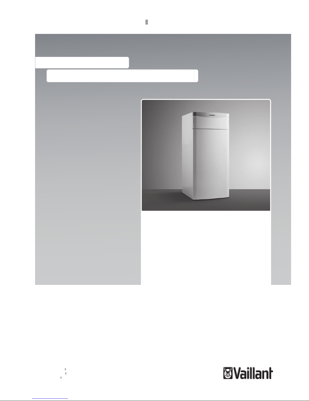
Vaillant flexoTHERM exclusive VWF 57/4, flexoTHERM exclusive VWF 87/4, flexoTHERM exclusive VWF 117/4 Installation And Maintenance Instructions Manual
Page 1
For the competent person
Installation and maintenance instructions
flexoTHERM exclusive
VWF 57/4 230 V
VWF 87/4 230 V
VWF 117/4 230 V
GB
Installation and maintenance instructions
Publisher/manufacturer
Vaillant GmbH
Berghauser Str. 40 D-42859 Remscheid
Tel. +49 21 91 18‑0 Fax +49 21 91 18‑28 10
info@vaillant.de www.vaillant.de
Page 2

Contents
2 Installation and maintenance instructions flexoTHERM exclusive 0020213395_00
Contents
1 Safety .................................................................... 4
1.1 Action-related warnings ......................................... 4
1.2 Intended use.......................................................... 4
1.3 General safety information .................................... 4
1.4 Regulations (directives, laws, standards) .............. 6
2 Notes on the documentation .............................. 7
2.1 Observing other applicable documents ................. 7
2.2 Storing documents................................................. 7
2.3 Applicability of the instructions .............................. 7
3 System overview.................................................. 7
3.1 Heat pump system design ..................................... 7
3.2 Functionality........................................................... 8
3.3 Safety devices ....................................................... 9
4 Product description........................................... 10
4.1 Product design..................................................... 10
4.2 Information on the identification plate.................. 10
4.3 Explanation of product stickers............................ 11
4.4 Type designation and serial number ................... 11
4.5 CE label ............................................................... 11
4.6 Benchmark........................................................... 11
5 Installation.......................................................... 12
5.1 Checking the scope of delivery............................ 12
5.2 Selecting the installation site ............................... 12
5.3 Dimensions.......................................................... 13
5.4 Minimum clearances............................................ 14
5.5 Transporting the heat pump ................................ 14
5.6 Installing the product............................................ 15
5.7 Removing carrying handles ................................. 15
5.8 Removing the front casing................................... 15
5.9 Removing the casing top and side casings ......... 16
5.10 Removing the refrigeration circuit cover .............. 16
6 Carrying out the hydraulics installation.......... 17
6.1 Requirements for the heating circuit.................... 17
6.2 Connecting the heat pump to the heating
circuit ................................................................... 17
6.3 Connecting the heat pump to the brine circuit ..... 17
6.4 Hydraulic wiring in the system ............................. 18
7 Filling and purging the system......................... 18
7.1 Filling and purging the heating circuit .................. 18
7.2 Filling and purging the brine circuit ...................... 19
8 Electrical installation......................................... 21
8.1 Routing eBUS lines.............................................. 21
8.2 Opening the electronics box ............................... 21
8.3 Switch box ........................................................... 22
8.4 Establishing the power supply ............................. 22
8.5 Mains connection PCB ........................................ 24
8.6 Controller PCB..................................................... 26
8.7 Connecting the system controller and
accessories to the electronics system ................. 28
8.8 Carrying out the wiring......................................... 28
8.9 Installing the VRC DCF........................................ 28
8.10 Installing optional accessories ............................. 28
8.11 Checking the electrical installation ...................... 28
8.12 Completing installation......................................... 28
9 Start-up ............................................................... 29
9.1 Operating concept ............................................... 29
9.2 Starting up the heat pump ................................... 29
9.3 Running the installation assistants ...................... 29
9.4 Calling up the installer level ................................. 30
9.5 Heating mode flow temperature regulation.......... 30
9.6 Calling up statistics .............................................. 30
9.7 Checking that the product works correctly........... 30
10 Adapting the unit to the heating
installation.......................................................... 30
10.1 Setting parameters .............................................. 30
10.2 Setting the high-efficiency pumps........................ 30
10.3 Setting the flow temperature in heating mode
(with no controller connected) ............................. 32
10.4 Setting the flow temperature in cooling mode
(with no controller connected) ............................. 32
10.5 Handing the product over to the operator ............ 32
11 Troubleshooting ................................................ 32
11.1 Displaying the Live Monitor (current product
status) .................................................................. 32
11.2 Checking fault codes ........................................... 33
11.3 Querying the fault memory .................................. 33
11.4 Resetting the fault memory.................................. 33
11.5 Restarting the installation assistant ..................... 33
11.6 Using check programmes .................................... 33
11.7 Carrying out the actuator test .............................. 33
11.8 Auxiliary electric heater circuit breaker ................ 33
12 Inspection and maintenance ............................ 33
12.1 Inspection and maintenance information............. 33
12.2 Procuring spare parts .......................................... 33
12.3 Inspection and maintenance check-list................ 34
12.4 Checking and correcting the filling pressure of
the heating installation......................................... 34
12.5 Checking and correcting the filling pressure in
the brine circuit .................................................... 34
12.6 Carrying out a restart and test operation ............. 34
13 Decommissioning.............................................. 34
13.1 Temporarily decommissioning the product.......... 34
13.2 Decommissioning the product ............................. 34
14 Recycling and disposal..................................... 34
14.1 Disposing of the brine fluid .................................. 35
14.2 Arranging disposal of coolant .............................. 35
15 Customer service............................................... 35
Appendix ............................................................................ 36
A Power supply 1~/N/PE 230 V (connection
diagram 1 = ).................................................. 36
B Power supply 3~/PE 230 V (connection
diagram 2 = ).................................................. 36
C Installer level overview...................................... 37
D Status codes – Overview .................................. 41
E Fault codes ......................................................... 43
Page 3

Contents
0020213395_00 flexoTHERM exclusive Installation and maintenance instructions 3
F Characteristic values for the VR 10 external
temperature sensor ........................................... 48
G Characteristic values for internal
temperature sensors ......................................... 49
H Characteristic values for the VRC DCF
outdoor temperature sensor............................. 50
I Heat pump schematic........................................ 51
J Commissioning Checklist ................................. 53
K Commissioning Checklist ................................. 56
L Technical data.................................................... 59
L.1 General................................................................ 59
L.2 Brine heat source................................................. 61
L.3 Groundwater heat source .................................... 63
M Measuring currents = In..................................... 65
Page 4
1 Safety
4 Installation and maintenance instructions flexoTHERM exclusive 0020213395_00
1 Safety
1.1 Action-related warnings
Classification of action-related warnings
The action-related warnings are classified in
accordance with the severity of the possible
danger using the following warning signs and
signal words:
Warning symbols and signal words
Danger!
Imminent danger to life or risk of
severe personal injury
Danger!
Risk of death from electric shock
Warning.
Risk of minor personal injury
Caution.
Risk of material or environmental
damage
1.2 Intended use
There is a risk of injury or death to the user or
others, or of damage to the product and other
property in the event of improper use or use
for which it is not intended.
The system is intended exclusively for domestic use.
The system is intended as a heat generator
with cooling function for closed heating installations and for hot water generation. Operation of the pump outside the application
limits results in the heat pump being switched
off by the internal control and safety devices.
Cooling mode with radiator heating systems
is not permitted since radiators do not have
an adequate heat transfer surface area.
Intended use includes the following:
– observance of accompanying operating,
installation and servicing instructions for
the product and any other system components
– installing and fitting the product in accord-
ance with the product and system approval
– compliance with all inspection and main-
tenance conditions listed in the instructions.
Intended use also covers installation in accordance with the IP class.
Any other use that is not specified in these
instructions, or use beyond that specified in
this document shall be considered improper
use. Any direct commercial or industrial use
is also deemed to be improper.
Caution.
Improper use of any kind is prohibited.
1.3 General safety information
1.3.1 Risk caused by inadequate
qualifications
The following work must only be carried out
by competent persons who are sufficiently
qualified to do so:
– Installation
– Disassembly
– Installation
– Start-up
– Maintenance
– Repair
– Decommissioning
▶ Observe all instructions that are included
with the product.
▶ Proceed in accordance with the current
state of technology.
▶ Observe all applicable directives, stand-
ards, laws and other regulations.
1.3.2 Risk of injury during transport due
to a high product weight.
▶ Make sure that the product is transported
by at least two people.
1.3.3 Risk of death due to lack of safety
devices
The schematic drawings included in this document do not show all safety devices required for correct installation.
▶ Install the necessary safety devices in the
system.
▶ Observe the applicable national and inter-
national laws, standards and guidelines.
Page 5

Safety 1
0020213395_00 flexoTHERM exclusive Installation and maintenance instructions 5
1.3.4 Risk of material damage caused by
frost
▶ Do not install the product in rooms prone
to frost.
1.3.5 Risk of death from electric shock
There is a risk of death from electric shock if
you touch live components.
Before commencing work on the product:
▶ Disconnect the product from the power
supply by switching off all power supplies
(electrical partition with a contact opening
of at least 3 mm, e.g. fuse or line protection switch).
▶ Secure against being switched back on
again.
▶ Wait for at least 3 minutes until the capa-
citors have discharged.
▶ Check that there is no voltage.
1.3.6 Risk of injury due to chemical burns
caused by brine fluid
The brine fluid ethylene glycol is harmful to
health.
▶ Avoid contact with the skin and eyes.
▶ Always wear gloves and protective
goggles.
▶ Do not inhale or swallow.
▶ Observe the safety data sheet that accom-
panies the brine fluid.
1.3.7 Risk of burns due to hot and cold
components
There is a risk of burns from any uninsulated
pipelines and from the auxiliary electric heating.
▶ Only carry out work on the components
once they have reached ambient temperature.
1.3.8 Material damage due to unsuitable
installation surface
The installation surface must be even and
have sufficient load-bearing capacity to support the operating weight of the product. An
uneven installation surface may cause leaks
in the product.
If the installation surface does not have sufficient load-bearing capacity, the product may
topple.
There is a risk of death if the connections are
subject to leaks.
▶ Make sure that the product is positioned
flush against the installation surface.
▶ Ensure that the installation surface has
sufficient load-bearing capacity to bear the
operating weight of the product.
1.3.9 Danger due to malfunctions
Ensure that the heating installation is in a
technically perfect condition.
▶ Ensure that no safety or monitoring
devices have been removed, bridged or
disabled.
▶ Immediately rectify any faults and damage
that may affect safety.
▶ Install the controller in a location where it is
not covered by furniture, curtains, or other
objects.
▶ If thermostatic control is activated, ad-
vise the operator that, in the room where
the controller is mounted, all the radiator
valves must be fully open.
▶ Do not use the units' free terminals as sup-
porting terminals for other wiring.
▶ At lengths of over 10 m, 230 V supply lines
must be laid separately from sensor or bus
lines.
1.3.10 Preventing the risk of injury from
freezing as a result of touching
coolant
The product is supplied with an operational
filling of R 410 A refrigerant. Escaping
coolant may cause freezing if the exit point is
touched.
▶ If coolant escapes, do not touch any com-
ponents of the product.
▶ Do not inhale any vapours or gases that
escape from the refrigerant circuit as a
result of leaks.
▶ Avoid skin or eye contact with the coolant.
▶ In the event of skin or eye contact with the
coolant, seek medical advice.
Page 6

1 Safety
6 Installation and maintenance instructions flexoTHERM exclusive 0020213395_00
1.3.11 Risk of material damage caused by
using an unsuitable tool
▶ Use the correct tool to tighten or loosen
screw connections.
1.3.12 Risk of material damage caused by
condensate inside the house
In heating mode, the lines between the heat
pump and the heat source (environment circuit) are cold, which means that condensate
may form on the lines in the house. In cooling mode, the building circuit lines are cold,
which means that condensate may also form
if the temperature falls below the dew point.
Condensate may lead to material damage,
for example due to corrosion.
▶ Ensure that you do not damage the heat
insulation on the lines.
1.3.13 Avoid environmental damage
caused by escaping coolant
The product contains R 410 A refrigerant.
The coolant must not be allowed to escape
into the atmosphere. R410A is a fluorinated
greenhouse gas covered by the Kyoto Protocol, with a GWP of 2088 (GWP = global
warming potential). If this gas escapes into
the atmosphere, its impact is 2088 times
greater than the natural greenhouse gas CO2.
Before the product is disposed of, the coolant
that is contained in it must be completely
drained into a suitable vessel so that it can
then be recycled or disposed of in accordance with regulations.
▶ Ensure that only officially certified com-
petent persons with appropriate protective
equipment carry out maintenance work on
the refrigerant circuit or access it.
▶ Arrange for the refrigerant that is contained
in the product to be recycled or disposed
of by a certified competent person in accordance with the regulations.
1.4 Regulations (directives, laws,
standards)
▶ Observe the national regulations, stand-
ards, guidelines and laws.
Page 7

Notes on the documentation 2
0020213395_00 flexoTHERM exclusive Installation and maintenance instructions 7
2 Notes on the documentation
2.1 Observing other applicable documents
▶ You must observe all the operating and installation in-
structions included with the system components.
2.2 Storing documents
▶ Pass these instructions and all other applicable docu-
ments on to the system operator.
2.3 Applicability of the instructions
These instructions apply only to:
Product
VWF 57/4 230V
VWF 87/4 230V
VWF 117/4 230V
3 System overview
3.1 Heat pump system design
A
B
A
B
The heat pump system consists of the following components:
– Heat pump
– System controller (from VRC 700)
– Outside temperature sensor with DCF receiver
– System sensor, if required
– With ground heat source: Ground sensor
– With well water heat source: Groundwater module
The heat pump system generates heat for heating installations and in hot water generation by extracting the thermal
energy from a heat source circuit and releasing this into
the heating circuit via the internal refrigeration circuit. At the
same time, there is an opportunity for active cooling to take
place via circulation reversal. The heat pump can be connected to two different types of heat source. This includes geothermal energy and groundwater, whereby the heat source is
connected to the heat pump via a transfer station connected
between the two.
3.1.1 Heat pump
– Fulfils the heating demand of the system controller down
to a minimum outside temperature and up to a maximum
target flow temperature.
– Fulfils the cooling requirements of the system controller
up to a maximum source temperature.
– Hot water generation with external domestic hot water
cylinder
3.1.2 Groundwater module
– Heat transfer from the groundwater to the brine heat
transfer medium in the heat pump.
3.1.3 Passive cooling module (optional)
– When using ground or groundwater as a heat source,
the heat of the heating water is transferred to the heat
source medium purely using circulation pumps and valve
switching.
Page 8
3 System overview
8 Installation and maintenance instructions flexoTHERM exclusive 0020213395_00
3.2 Functionality
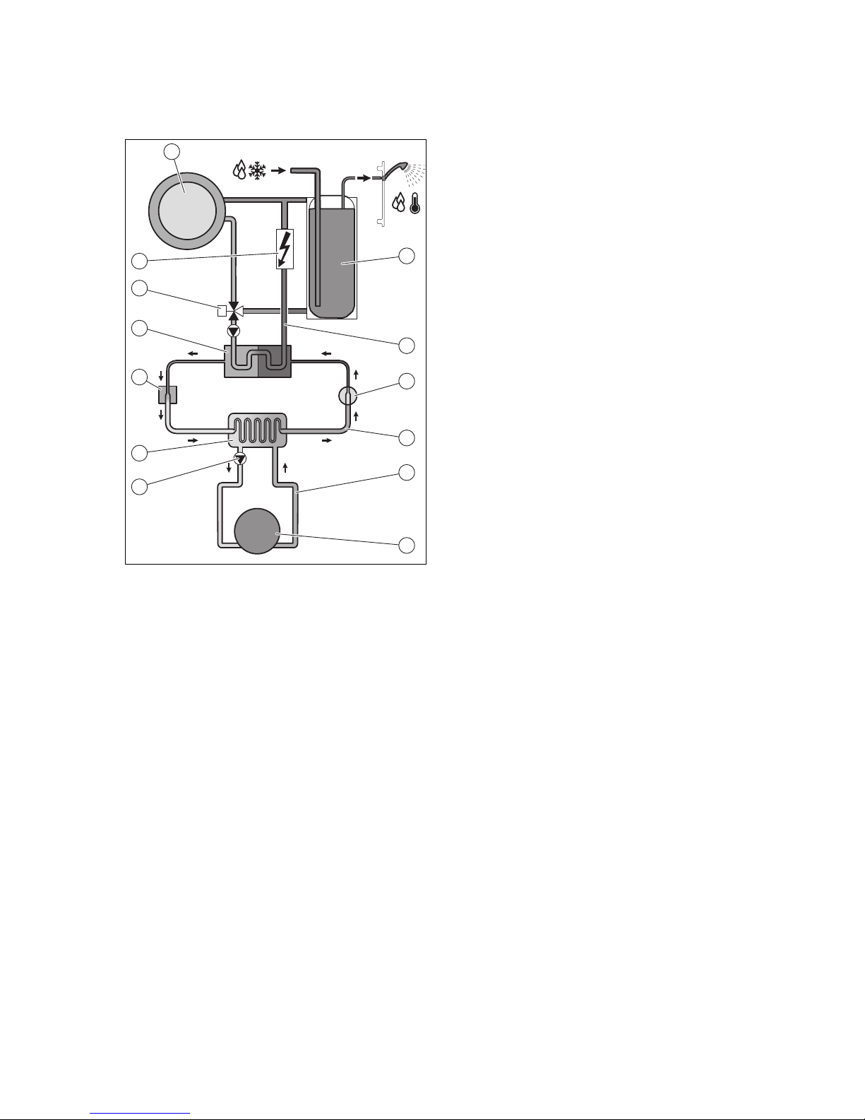
3.2.1 Heat pump
2
3
1
4
5
6
7
8
9
10
11
12
13
1 Heating installation
2 Domestic hot water
cylinder (optional)
3 Heating circuit
4 Compressor
5 Refrigeration circuit
6 Brine circuit
7 Heat source
8 Brine pump
9 Evaporator
10 Electronic expansion
valve
11 Condenser
12 Heating/cylinder char-
ging diverter valve
13 Auxiliary electric heating
The heat pump system uses geothermal energy or groundwater as the heat source.
The heat pump consists of the following separate circuits
which are coupled with one another by means of heat exchangers. These circuits are:
– The brine circuit, which extracts the thermal energy from
the ground or the groundwater and transfers it to the refrigeration circuit
– The refrigerant circuit, which is used to bring the thermal
energy from the heat source to a usable, higher temperature level and deliver it to the heating circuit
– The heating circuit, which is used to heat up the living
rooms
The coolant circuit is connected via the evaporator to the
heat source, from which it extracts thermal energy. At the
same time, the physical state of the coolant changes; it
evaporates. The refrigerant circuit is connected via the
condenser to the heating installation, to which it releases the
thermal energy again. In so doing, the coolant becomes
liquid again; it condenses.
As thermal energy can only pass from a body at a higher
temperature to a body at a lower temperature, the coolant in
the evaporator must have a lower temperature than the heat
source. On the other hand, the temperature of the coolant in
the condenser must be higher than that of the heating water
in order to be able to release the thermal energy to it.
These different temperatures are produced in the coolant
circuit by means of a compressor and an expansion valve,
which are located between the evaporator and condenser.
The coolant flows in vapour form from the evaporator into the
compressor, where it is compressed. This causes the pressure and temperature of the coolant vapour to rise sharply.
After this process, it flows through the condenser, where it
releases its thermal energy to the heating water by condensation. It flows as a liquid into the expansion valve, where
it expands significantly and, in so doing, loses much of its
pressure and temperature. This temperature is now lower
than that of the brine that flows through the evaporator. The
coolant can thus absorb more thermal energy in the evaporator, turning into vapour in the process and flowing to the
compressor. The cycle starts again.
The evaporator and parts of the refrigerant circuit inside the
heat pump are cold-insulated, meaning that no condensate
can accumulate. Any small amounts of condensate which
may form evaporate as a result of the heat generated inside
the heat pump.
The product is equipped with an active cooling function
that you can use to maintain the temperature of your living
rooms when the outside temperature is high during summer.
Ground and groundwater are particularly good heat sources
for this use. For this purpose, a 4-way diverter valve is
integrated into the heat pump's refrigerant circuit. This uses
the principle of active cooling, in which the refrigerant circuit
is used to extract thermal energy from the heat recovery
system (e.g. the underfloor heating) in order to deliver this to
the heat source. For this, the 4-way diverter valve is used
to hydraulically swap the heat exchange processes in the
evaporator and condenser in the refrigerant circuit.
The heating water, which, when supplied, is colder in the
flow than the room temperature, absorbs thermal energy
from the rooms and is pumped by the heating pump to the
condenser (which works as an evaporator when in cooling
mode). This thermal energy is absorbed by the coolant and
heated to a higher temperature level using the compressor.
The thermal energy is then delivered to the brine in the evaporator (which works as a condenser when in cooling mode).
The cooled coolant is guided to the expansion valve to enable thermal energy to be absorbed from the condenser
again. The brine pump transports the hot brine into the earth,
where the thermal energy is dissipated.
During the installation, it may be useful to exclude some
rooms (e.g. the bathroom) from the cooling function and to
actuate stop valves especially for this. The heat pump electronics system emits a signal that can be used for actuating
these.
A passive cooling module is also available as an alternative,
whereby thermal energy is transported via underfloor heating, for example, from the rooms to the ground without the
compressor operating and therefore without the refrigerant
circuit operating.
If required, the integrated auxiliary electric heating can be
activated at different output levels via the heat pump display.
The auxiliary electric heating is then actuated by the system
controller.
Page 9

System overview 3
0020213395_00 flexoTHERM exclusive Installation and maintenance instructions 9
3.2.2 Weather-controlled system controller
The heat pump system is equipped with a weather-controlled
system controller that provides heating, cooling and hot water handling depending on the control type and controls this
in automatic mode.
The controller changes the target flow temperature based on
the outside temperature. The outside temperature is measured by a separate sensor which is mounted in the open air,
and the results are transmitted to the controller. The room
temperature depends only on the preset values. The system
compensates for the effect of the outside temperature. Hot
water generation is not affected by the weather compensation. The instructions for the system controller describe how
to install and operate the product.
3.3 Safety devices
3.3.1 Frost protection function
The frost protection function for the system is controlled via
the system controller. If the system controller fails, the heat
pump guarantees limited frost protection for the heating circuit.
3.3.2 Protection against low heating water
pressure
This function continuously monitors the pressure of the heating water in order to prevent a possible loss of heating water.
If the water pressure falls below the minimum pressure, an
analogue pressure sensor switches off the heat pump and
switches the other modules, where these exist, to standby
mode. It switches the heat pump on again if the water pressure reaches the operating pressure.
– Min. heating circuit pressure: ≥ 0.05 MPa (≥ 0.50 bar)
– Min. heating circuit operating pressure: ≥ 0.07 MPa
(≥ 0.70 bar)
3.3.3 Brine loss protection system
The brine loss protection system continuously monitors the
fluid pressure in the environment circuit in order to prevent a
possible shortage of fluid. If the fluid pressure falls below the
minimum pressure, an analogue pressure sensor switches
off the heat pump and switches the other modules, where
these exist, to standby mode. It switches the heat pump on
again if the fluid pressure reaches the operating pressure.
– Minimum brine fluid pressure: ≥ 0.05 MPa (≥ 0.50 bar)
– Min. brine fluid operating pressure: ≥ 0.07 MPa
(≥ 0.70 bar)
3.3.4 Freeze protection
This function prevents the evaporator from freezing when the
heat source temperature drops below a certain value.
The outlet temperature of the heat source is constantly
measured. If the outlet temperature of the heat source falls
below a certain value, the compressor temporarily switches
off and displays a status message. If this fault occurs three
times in a row, it is switched off and a fault message is
displayed.
3.3.5 Pump- and valve-blocking protection
system
This function prevents the pumps for heating water and
brine and all diverter valves from sticking. The pumps and
the valves, which were out of operation for 23 hours, are
switched on for 10 - 20 seconds, one after the other.
3.3.6 High-pressure pressure switch in the
refrigeration circuit
The high-pressure pressure switch shuts down the heat
pump if the pressure in the coolant circuit is too high. If the
pressure in the heat pump's refrigeration circuit exceeds
the maximum pressure, the high-pressure pressure switch
temporarily shuts down the heat pump. Following a waiting
period, another attempt is made to start the heat pump. After
three failed start attempts in succession, a fault message is
displayed.
– Refrigeration circuit pressure max.: 4.60 MPa (g) (46.00
bar (g))
– Waiting period: 5 minutes (after the first occurrence)
– Waiting period: 30 minutes
(after the second and every further occurrence)
The fault counter is reset if both of the following conditions
are met:
– Heat requirement without switching off prematurely
– 60 minutes of uninterrupted operation
3.3.7 Hot gas thermostat in the refrigeration
circuit
The hot gas thermostat shuts down the heat pump if the temperature in the refrigeration circuit is too high. If the temperature in the heat pump's refrigeration circuit exceeds the
maximum temperature, the hot gas thermostat temporarily shuts down the heat pump. Following a waiting period,
another attempt is made to start the heat pump. After three
failed start attempts in succession, a fault message is displayed.
– Max. refrigeration circuit temperature: 135 ℃
– Waiting period: 5 minutes (after the first occurrence)
– Waiting period: 30 minutes
(after the second and every further occurrence)
The fault counter is reset if both of the following conditions
are met:
– Heat requirement without switching off prematurely
– 60 minutes of uninterrupted operation
3.3.8 Safety cut-out (SCO) in the heating circuit
If the temperature in the heating circuit of the internal auxiliary electric heating exceeds the maximum temperature, the
SCO shuts down the auxiliary electric heating as a securing measure. Following a waiting period, another attempt is
made to start the auxiliary electric heating. A fault message
is displayed that can only be reset by pressing the Reset button or by switching the heat pump off and on again.
– Max. heating circuit temperature: 85 ℃
Page 10
4 Product description
10 Installation and maintenance instructions flexoTHERM exclusive 0020213395_00
4 Product description
4.1 Product design
4.1.1 Front view, open
1
2
3
4
5
6
7
12
13
14
15
10
11
9
8
1 Switch box
2 Operator control panel
3 Auxiliary electric heating
4 Condenser
5 Heating pump
6 Electronic expansion
valve EVI (intermediate
circuit injection)
7 Heating circuit filling
and drainage tap
8 Carrying handles for
transport
9 Compressor
10 Electronic expansion
valve
11 Brine circuit filling and
drainage tap
12 Brine circuit pump
13 Evaporator (not visible)
14 Heating/cylinder char-
ging diverter valve
15 4-way valve
4.1.2 Rear view
1
2
4
3
5
6
7
1 Connection: From the
heat pump to the heat
source (cold brine, B)
2 Connection: From the
heat source to the heat
pump (hot brine, A)
3 Hot water return
4 Heating circuit dia-
phragm expansion tank
connection
5 Heating return
6 Heating flow
7 Recessed handles and
cable duct
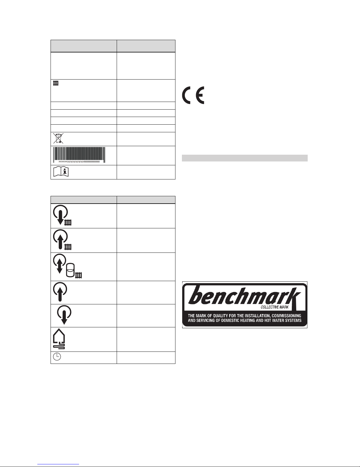
4.2 Information on the identification plate
Information on the identification plate
Meaning
Rated voltage of the compressor, pumps and controller
Auxiliary heater rated voltage
P Max
Max. rated power of the
compressor, pumps and
controller
P Max
Max. rated power of the
auxiliary heater
I +
30 A
+
Start-up current
Coolant type, fill quantity,
permissible rated overpressure
COP B0/W35 /W45 /W55 Output figure (coefficient
of performance) at a brine
temperature of 0 °C and
heating flow temperature of
35/45/55 °C
B0/W35 /W45 /W55
Heating output at a brine
temperature of 0 °C and
heating flow temperature of
35/45/55 °C
Page 11
Product description 4
0020213395_00 flexoTHERM exclusive Installation and maintenance instructions 11
Information on the identification plate
Meaning
COP W10/W35 /W45 /W55 Output figure (coefficient of
performance) at a groundwater temperature of 10 °C and
a heating flow temperature
of 35/45/55 °C
W10/W35 /W45 /W55
Heating output at a groundwater temperature of 10 °C
and a heating flow temperature of 35/45/55 °C
V Mains voltage
Hz Power frequency
W Power consumption
IP Protection class
Information on disposal
Barcode with serial number,
7th to 16th digits = product
article number
Read the instructions
4.3 Explanation of product stickers
Symbol on the sticker Meaning
Heating flow connection
Heating return connection
Heating diaphragm expansion tank connection
A
Connection from the heat
source to the heat pump (hot
brine)
B
Connection from the heat
pump to the heat source
(cold brine)
Brine heat source
Energy supply company anticycling time
4.4 Type designation and serial number
The type designation and serial number can be found on
a plate behind the front flap and on the main identification
plate. The 7th to 16th digits of the serial number form the
article number.
4.5 CE label
The CE label shows that the products comply with the basic
requirements of the applicable directives as stated on the
identification plate.
The declaration of conformity can be viewed at the manufacturer's site.
4.6 Benchmark
Applicability: Great Britain
Vaillant is a licensed member of the Benchmark Scheme.
Benchmark places responsibilities on both manufacturers
and installers. The purpose is to ensure that customers are
provided with the correct equipment for their needs, that it is
installed, commissioned and serviced in accordance with the
manufacturer’s instructions by a competent person approved
at the time by the Health and Safety Executive and that it
meets the requirements of the appropriate Building Regulations. The Benchmark Checklist can be used to demonstrate compliance with Building Regulations and should be
provided to the customer for future reference.
Installers are required to carry out installation, commissioning and servicing work in accordance with the Benchmark
Code of Practice which is available from the Heating and
Hotwater Industry Council who manage and promote the
Scheme.
Benchmark is managed and promoted by the Heating and
Hotwater Industry Council.
For more information visit www.centralheating.co.uk
Page 12

5 Installation
12 Installation and maintenance instructions flexoTHERM exclusive 0020213395_00
5 Installation
5.1 Checking the scope of delivery
1. Carefully remove the packaging and padding without
damaging the parts of the product.
2. Check that the scope of delivery is complete.
Quantity Description
1 Heat pump
1 Installation set comprising
– 3 x flat seal (yellow/green) for heating
circuit
– 1 x 3/4" flat seal for the heating expansion
vessel connection
– 2 x O-ring seals for brine circuit
1 Expansion relief valve for brine circuit, 1/2",
3 bar
1 Enclosed documentation
5.2 Selecting the installation site
▶ Select a dry room that is frost-proof throughout and in
which the permissible ambient temperature is neither
above nor below the permitted range.
– Permissible ambient temperature: 7 … 25 ℃
– Permissible relative air humidity: 40 … 75 %
▶ Ensure that the installation room has the required min-
imum volume.
Heat pump R 410 A refri-
gerant filling
volume
Minimum installation room
volume
VWF 57/4 230V 1.50 kg 3.41 m³
VWF 87/4 230V 2.40 kg 5.45 m³
VWF 117/4 230V 2.50 kg 5.68 m³
▶ Ensure that the required minimum clearances can be
maintained.
▶ When selecting the installation site, you must take into
consideration that when the heat pump is in operation, it
will transfer vibrations to the floor and the nearby walls.
▶ Ensure that the floor is level and has sufficient load-bear-
ing capacity to bear the weight of the heat pump and a
domestic hot water cylinder.
▶ Ensure that cables can be easily routed (for brine, hot
water and heating).
Page 13
Installation 5
0020213395_00 flexoTHERM exclusive Installation and maintenance instructions 13
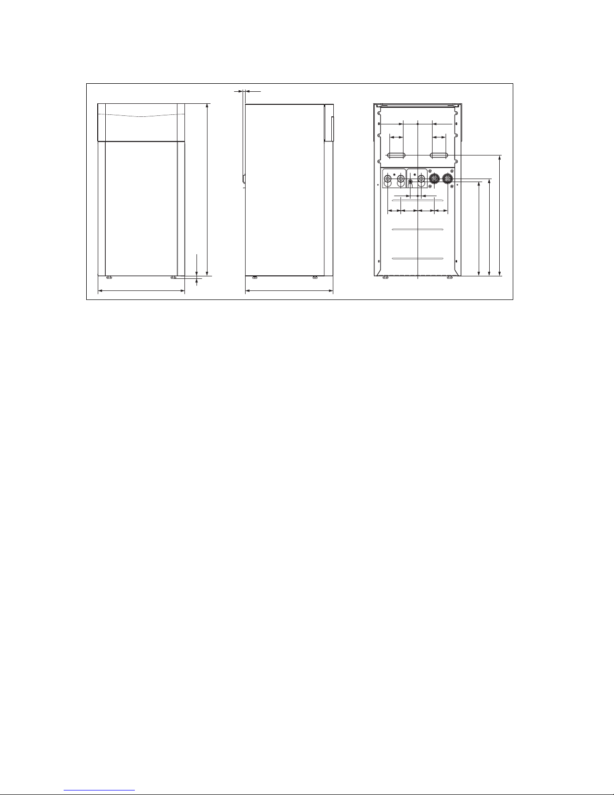
5.3 Dimensions
671
651
595 600
20
833
1183
18,2
91
100 100
91
2550
90 115 115 90
Page 14
5 Installation
14 Installation and maintenance instructions flexoTHERM exclusive 0020213395_00
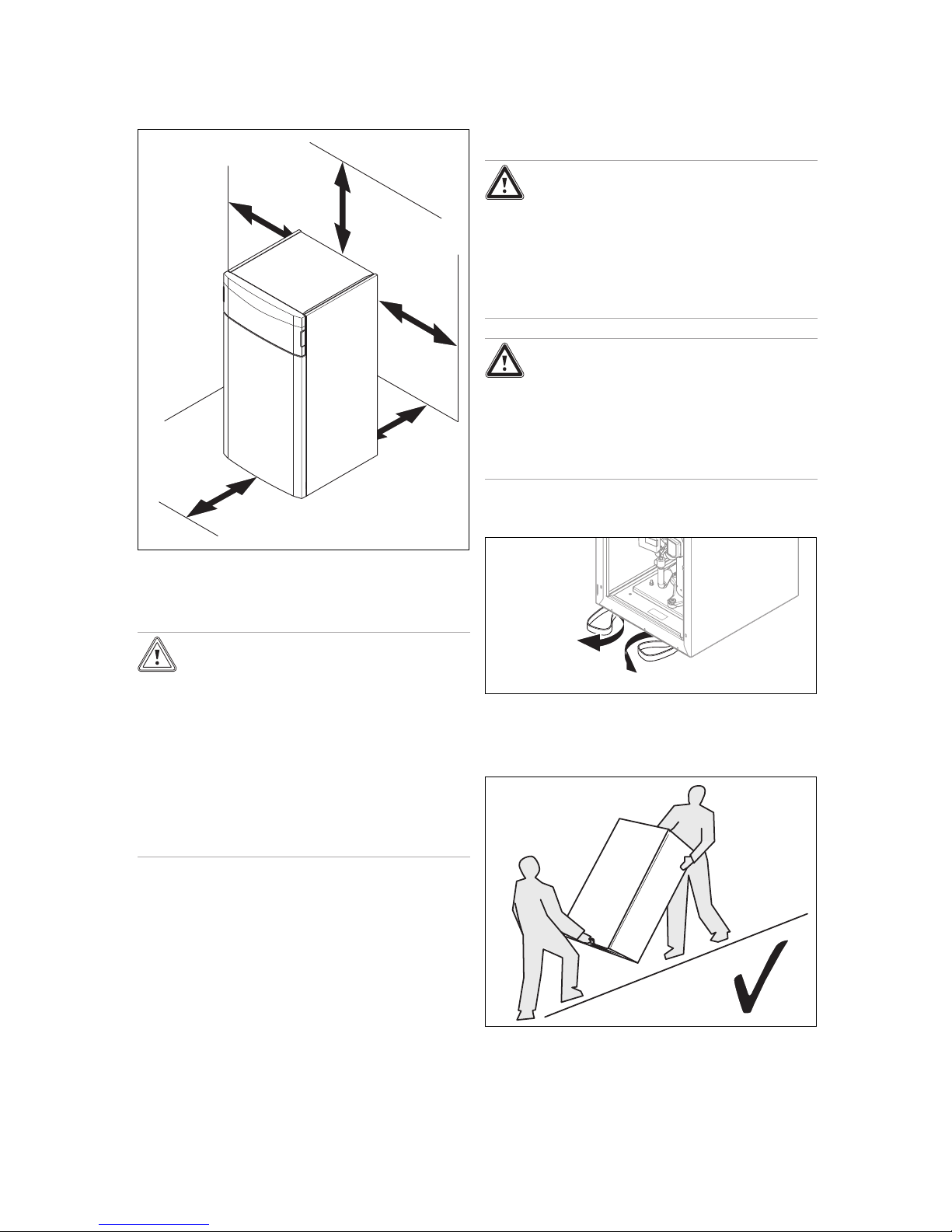
5.4 Minimum clearances
200 mm
250 mm
300 mm
300 mm
300 mm
▶ Comply with the minimum clearances specified above in
order to facilitate maintenance work.
5.5 Transporting the heat pump
Caution.
Risk of damage due to improper trans-
portation.
Regardless of the mode of transport, the heat
pump must never be tilted by more than 45°.
Otherwise, this may lead to malfunctions in
the coolant circuit during subsequent operation. In the worst case scenario, this may lead
to a fault in the whole system.
▶ During transport, do not tilt the heat pump
by any more than the maximum angle of
45°.
▶ Transport the product to the installation site. Use the
recessed handles on the rear and the retractable straps
at the front on the underside of the product as an aid.
▶ Transport the product using a suitable sack truck. Only
position the sack truck at the rear so that the weight distribution is as even as possible. Secure the product using
a retaining strap.
▶ Use a ramp to move the product from the pallet using
the sack truck, e.g. a piece of square timber and a sturdy
board.
5.5.1 Using carrying handles
1. Remove the front casing. (→ Page 15)
Danger!
Risk of injury due to repeated use of the
carrying handles.
Due to material ageing, the carrying handles
are not designed to be reused during any
subsequent transportation.
▶ Once the product has been started up, cut
off the carrying handles.
Danger!
Risk of injury when transporting due to
the carrying handles breaking away.
The carrying handles may break away during
transport if the front casing is fitted.
▶ Remove the front casing before you use
the carrying handles.
2. To transport the unit safely, use the two carrying
handles on the two front feet of the product.
3. Turn the carrying handles under the product so that
they face forwards.
4. Ensure that the feet are screwed in fully so that the carrying handles are held properly.
5. Always transport the product as illustrated above.
Page 15

Installation 5
0020213395_00 flexoTHERM exclusive Installation and maintenance instructions 15
6. Never transport the product as illustrated above.
5.6 Installing the product
0-10 mm
▶ Orientate the product horizontally by adjusting the ad-
justable feet.
5.7 Removing carrying handles
▶ Cut off the carrying handles and throw them away.
5.8 Removing the front casing
1
1. Remove the front flap on the operator control panel by
taking hold of the recessed handles with both hands
and lifting off the front flap towards you.
4x
2. Turn the four screws by a quarter turn and lift off the
cover on the operator control panel towards you.
Page 16

5 Installation
16 Installation and maintenance instructions flexoTHERM exclusive 0020213395_00
A
B
3. Pull each part of the front casing forwards slightly and
remove it by lifting it upwards.
5.9 Removing the casing top and side casings
1. Pull the casing top forwards slightly and remove it by
lifting it upwards.
A
A
B
B
2. To remove a side casing, remove the four screws at the
front and the three screws at the back.
3. Remove the side casing.
5.10 Removing the refrigeration circuit cover
A
B
1. Remove the four screws.
2. Pull the top of the refrigeration circuit cover forwards
and lift it out of the guide.
Page 17
Carrying out the hydraulics installation 6
0020213395_00 flexoTHERM exclusive Installation and maintenance instructions 17
6 Carrying out the hydraulics
installation
1. If you want to carry out active cooling using ground as
the heat source, make sure that the borehole/ground
sensor is suitable for this purpose and observe the national directives and laws. The use of ground collectors
for active cooling is prohibited.
2. Flush the heating installation through thoroughly before connecting the heat pump in order to remove any
residue which could be deposited in the heat pump and
lead to damage.
3. Install the supply lines (disconnected from the power
supply) in accordance with the dimension and connection drawings.
– Position the pipe brackets for securing the heating
circuit and brine circuit piping so that they are not
too close to the heat pump in order to prevent noise
transmission.
– If required, instead of pipe brackets, use cold insu-
lation clamps with additional rubber insulation and,
in some cases, reinforced hoses (armoured rubber
hoses).
– To prevent excessive pressure losses, do not use
stainless steel corrugated pipes.
– If required, use horizontal or right-angled connection
adaptors from the accessories.
Note
The heat pump's compressor has two-fold
vibration insulation. This eliminates vibrations in the coolant circuit that are inherent in
the system. However, under certain circumstances, residual vibrations may occur.
4. Attach automatic purging valves to the heating installation.
6.1 Requirements for the heating circuit
In heating installations that are equipped primarily with thermostatic or electrically controlled valves, a constant and sufficient flow through the heat pump must be ensured. Irrespective of which heating installation is selected, the minimum volume of circulating heating water (35% of the nominal flow; see the Technical data table) must be guaranteed.
6.2 Connecting the heat pump to the heating
circuit
Caution.
Risk of damage from magnetite deposits.
In heating installations with steel pipes,
static heating surfaces and/or buffer cylinder
systems, magnetite may form where large
volumes of water are involved.
▶ Insert a magnetite filter to protect the
pump inside the product.
▶ You must position the filter in direct prox-
imity to the return line to the heat pump.
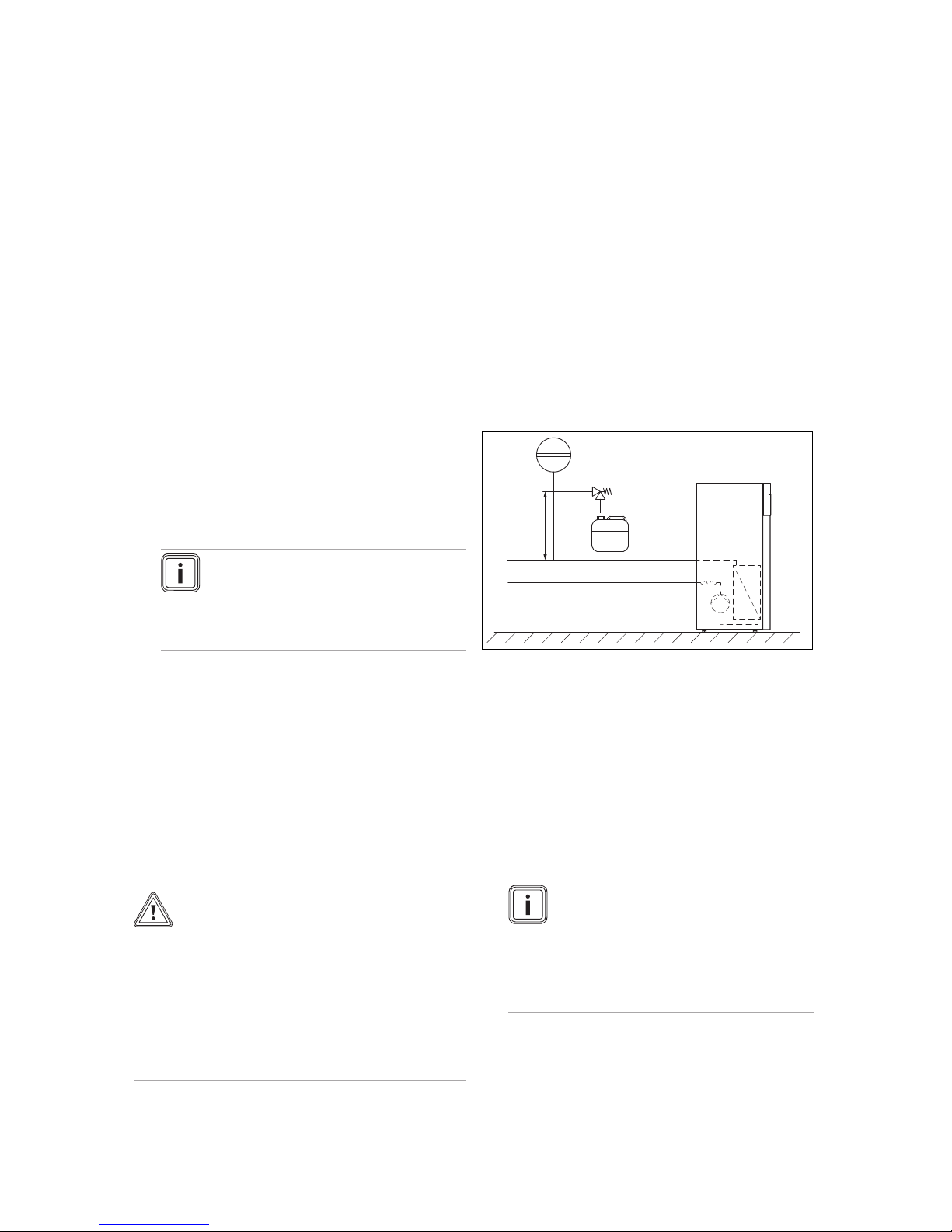
1. Install a diaphragm expansion tank at the heat pump
connection provided.
2. Install an expansion relief valve (at least DN 20, opening pressure of 3 bar) with pressure gauge.
3. Install the expansion relief valve hose in a frost-free
environment and ensure that its routing ends in an open
tundish where it is then visible.
4. Install an air/dust separator in the return of the heating
circuit.
5. Connect the heating flow to the heating flow connection
of the heat pump.
6. Connect the heating return to the heating return connection of the heat pump.
7. Insulate all of the pipes in the heating circuit and the
connections for the heat pump so that they are vapourdiffusion-tight in order to prevent them from falling below the dew point in cooling mode.
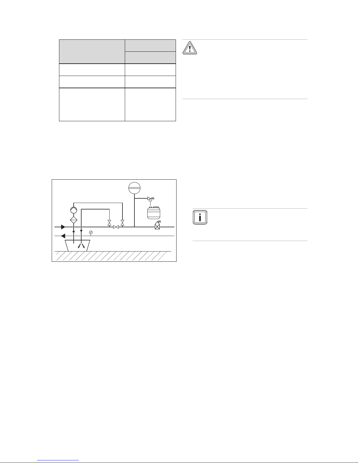
6.3 Connecting the heat pump to the brine
circuit
29
71
≥100 mm
42a
65
A
B
29 Brine pump
42a Brine expansion relief
valve
65 Brine collecting con-
tainer
71 Brine diaphragm expan-
sion tank
A From the heat source
to the heat pump (hot
brine)
B From the heat pump to
the heat source (cold
brine)
1. Remove the blind caps from the brine connections.
These are no longer required and can be properly disposed of.
2. Connect the brine lines to the heat pump.
3. Insulate all of the brine lines and the connections of the
heat pump so that they are vapour-diffusion-tight.
Note
Vaillant recommends that you install the
Vaillant heat pump brine filling unit (not
required when installing the groundwater
module). By doing this, it is then possible to
carry out a preparatory partial bleed of the
brine circuit, e. g. the flow and return lines of
the brine circuit to the product.
Page 18
7 Filling and purging the system
18 Installation and maintenance instructions flexoTHERM exclusive 0020213395_00
6.4 Hydraulic wiring in the system
6.4.1 Installing heating circuits with direct
connection
1. Install the hydraulic components in accordance with
the local requirements as shown in the system diagram
example, → Installation instructions for the system.
2. Connect the underfloor heating circuits or heating circuit
distributors directly to the heat pump.
3. Connect a limit thermostat to ensure that the heat
pump's underfloor protection works correctly.
(→ Page 22)
4. Ensure that a minimum volume of circulating water is
guaranteed.
– Minimum volume of circulating water: 35% of the
nominal flow
6.4.2 Installing heating circuits with direct
connection and domestic hot water cylinder
1. Install the heating circuits for direct operation.
(→ Page 18)
2. Secure the temperature sensor (VR10), available from
the range of accessories, in the domestic hot water
cylinder and connect it to the heat pump.
7 Filling and purging the system
7.1 Filling and purging the heating circuit
7.1.1 Checking and treating the heating
water/filling and supplementary water
Caution.
Risk of material damage due to poor-qual-
ity heating water
▶ Ensure that the heating water is of suffi-
cient quality.
▶ Before filling or topping up the system, check the quality
of the heating water.
Checking the quality of the heating water
▶ Remove a little water from the heating circuit.
▶ Check the appearance of the heating water.
▶ If you ascertain that it contains sedimentary materials,
you must desludge the system.
▶ Use a magnetic rod to check whether it contains mag-
netite (iron oxide).
▶ If you ascertain that it contains magnetite, clean the sys-
tem and apply suitable corrosion-protection measures, or
fit a magnet filter.
▶ Check the pH value of the removed water at 25 °C.
▶ If the value is below 8.2 or above 10.0, clean the system
and treat the heating water.
▶ Ensure that oxygen cannot get into the heating water.
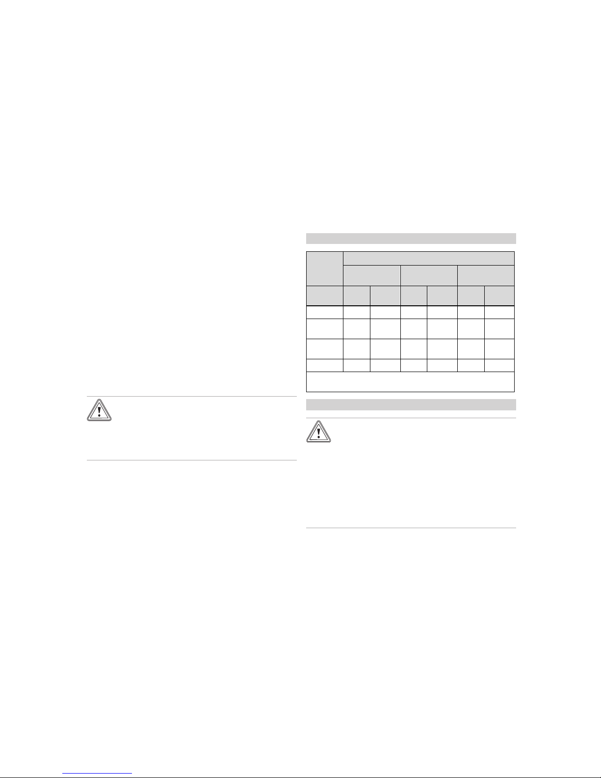
Checking the filling and supplementary water
▶ Before filling the system, measure the hardness of the
filling and supplementary water.
Treating the filling and supplementary water
▶ Observe all applicable national regulations and technical
standards when treating the filling and supplementary
water.
Provided the national regulations and technical standards
do not stipulate more stringent requirements, the following
applies:
You must treat the heating water in the following cases:
– If the entire filling and supplementary water quantity dur-
ing the operating life of the system exceeds three times
the nominal volume of the heating installation, or
– If the guideline values listed in the following table are not
met, or
– If the pH value of the heating water is less than 8.2 or
more than 10.0.
Applicability: Great Britain
Total
heating
output
Water hardness at specific system volume
1)
≤ 20 l/kW
> 20 l/kW
≤ 50 l/kW
> 50 l/kW
kW
ppm
CaCO₃
mol/m³ppm
CaCO₃
mol/m³ppm
CaCO₃
mol/
m³
< 50 < 300 < 3 200 2 2 0.02
> 50
to ≤ 200
200 2 150 1.5 2 0.02
> 200
to ≤ 600
150 1.5 2 0.02 2 0.02
> 600 2 0.02 2 0.02 2 0.02
1) Nominal capacity in litres/heating output; in the case of multiboiler systems, the smallest single heating output is to be used.
Applicability: Great Britain
Caution.
Risk of material damage if the heating
water is treated with unsuitable additives.
Unsuitable additives may cause changes in
the components, noises in heating mode and
possibly subsequent damage.
▶ Do not use any unsuitable frost and cor-
rosion protection agents, biocides or sealants.
No incompatibility with our products has been detected to
date with proper use of the following additives.
▶ When using additives, follow the manufacturer's instruc-
tions without exception.
We accept no liability for the compatibility of any additive or
its effectiveness in the rest of the heating system.
Additives for cleaning measures (subsequent
flushing required)
– Fernox F3
– Sentinel X 300
– Sentinel X 400
Additives intended to remain permanently in the
system
– Fernox F1
Page 19
Filling and purging the system 7
0020213395_00 flexoTHERM exclusive Installation and maintenance instructions 19
– Fernox F2
– Sentinel X 100
– Sentinel X 200
Additives for frost protection intended to remain
permanently in the system
– Fernox Antifreeze Alphi 11
– Sentinel X 500
▶ If you have used the above-mentioned additives, inform
the operator about the measures that are required.
▶ Inform the operator about the measures required for frost
protection.
7.1.2 Filling and purging the heating installation
1. Open all of the thermostatic radiator valves on the heating installation and, if required, all other stop valves.
2. Check all of the connections and the entire heating installation for leaks.
1
3. Push the white switching lever (1) on the motor head
of the diverter valve until it engages in its mid-position
in order to move the heating/cylinder charging diverter
valve into the mid-position.
◁ Both valves are open and the filling procedure is
improved since the air in the system can escape.
4. Connect a filling loop to the hot water supply.
5. Unscrew the screw cap from the heating circuit's filling
and drain valve and secure the free end of the filling
hose to here.
6. Open the filling and drain valve for the heating circuit.
7. Open the heating water supply slowly.
8. Fill with water until the pressure gauge (on-site) shows
that the heating installation has reached a pressure of
approx. 1.5 bar.
9. Close the filling and drain valve for the heating circuit.
10. Purge the heating circuit at the locations provided for
this.
11. Purge the heating pump using the heating pump's drain
screw.
12. Check the heating installation pressure again (if re-
quired, repeat the filling procedure).
13. Remove the filling loop from the filling and drain valve
and screw the screw cap back on.
Moving the heating/cylinder charging diverter
valve into the starting position
45°
A
B
C
D
14. Remove the power supply cable from the motor head of
the diverter valve.
15. Push the locking lever.
16. Turn the motor head by 45°.
17. Remove the motor head.
Note
This moves the spring in the valve body back
into the starting position.
18. Turn the motor head back towards the valve body and
reconnect the power supply cable.
Note
The white switch lever on the motor head
of the diverter valve should now be in the
starting position.
7.2 Filling and purging the brine circuit
7.2.1 Mixing the brine fluid
The brine fluid consists of water mixed with a concentrated
frost protection agent. The brine fluids that may be used differ greatly from region to region. For more information, contact the responsible authorities.
Only the brine fluids named here are authorised by Vaillant
for operating the heat pump.
Alternatively, suitable ready-mixed fluids for heat pumps can
be ordered from Vaillant.
▶ Use a sufficiently large mixing container.
▶ Carefully mix ethylene glycol with water.
Approved environment
source
Ground/groundwater
module
Brine content 30% vol.
Water content 70% vol.
* Cloud point
** Cold protection
Above this temperature,
the first ice crystals start
to form in the brine fluid.
At this temperature, half
of the fluid volume has
frozen; there is slush ice.
Page 20
7 Filling and purging the system
20 Installation and maintenance instructions flexoTHERM exclusive 0020213395_00
Approved environment
source
Ground/groundwater
module
Cloud point* of the aqueous
ethylene glycol mixture
-16 °C
Cold protection** of the aqueous
ethylene glycol mixture
-18 °C
* Cloud point
** Cold protection
Above this temperature,
the first ice crystals start
to form in the brine fluid.
At this temperature, half
of the fluid volume has
frozen; there is slush ice.
▶ Check the mixture ratio of the brine fluid.
– Working materials: Refractometer
In the event of special requirements, the following heat transfer media are also authorised by Vaillant for the ground and
groundwater heat sources:
– Aqueous solution with 33% ± 1% vol. propylene glycol
7.2.2 Filling the brine circuit
66
48
62
71
37
A
B
42a
63
61
33
67
65
33 Dirt filter
37 Automatic air separator
42a Brine expansion relief
valve
48 Pressure gauge (op-
tional)
61 Stop valve
62 Stop valve
63 Stop valve
65 Brine collecting con-
tainer
66 Brine container
67 Filling pump
71 Brine diaphragm expan-
sion tank
A From the heat source
to the heat pump (hot
brine)
B From the heat pump to
the heat source (cold
brine)
1. Install a dirt filter (33) in the pressure line.
2. Connect the filling pump's pressure line to the stop
valve (62).
3. Close the stop valve (63).
4. Open the stop valve (62).
5. Connect a hose, which leads to the brine fluid, to the
stop valve (61).
6. Open the stop valve (61).
Caution.
Risk of material damage caused by an
incorrect filling direction.
If you fill the brine pump against the direction
of flow, this may lead to a turbine effect which
can damage the pump's electronics.
▶ Ensure that the brine pump is filled in the
direction of flow.
7. Use the filling pump (67) to pour the brine fluid from the
brine container (66) into the brine circuit.
7.2.3 Purging the brine circuit
1. Start up the filling pump (67) in order to fill and rinse the
brine circuit.
2. Allow the filling pump (67) to run for at least 10 minutes
in order to fill and rinse the circuit sufficiently.
3. Then close the stop valves (61) and (62) and switch off
the filling pump (67).
4. If required, repeat this rinsing process.
5. Open the stop valve (63).
7.2.4 Building up pressure in the brine circuit
1. Use the filling pump (67) to pressurise the brine circuit.
Note
To operate the brine circuit without any problems, a filling pressure of 0.17 MPa (1.7 bar)
is required. The expansion relief valve opens
at 0.3 MPa (3 bar).
2. Read off the pressure on a pressure gauge (on-site).
– Brine fluid operating pressure range: 0.07
… 0.20 MPa (0.70 … 2.00 bar)
3. Build up the pressure in the brine circuit by opening the
stop valve (62) and using the filling pump to top up the
brine fluid.
4. If required, reduce the pressure in the brine circuit by
opening the stop valve (61) to drain brine fluid.
5. Check the brine circuit's filling pressure in the heat
pump's display.
6. If required, repeat the process.
7. Remove the two hoses from the valves (61) and (62).
8. Purge the system once more after starting up the heat
pump.
9. Label the container that holds the remaining brine fluid
with information about the type of brine fluid and the set
concentration.
10. Pass the vessel with the remaining brine fluid on to
the operator to be stored. Point out to the operator that
there is a risk of injury when handling brine fluid.
Page 21
Electrical installation 8
0020213395_00 flexoTHERM exclusive Installation and maintenance instructions 21
8 Electrical installation
Danger!
Risk of death from electric shock caused
by a residual-current circuit breaker not
working.
In certain cases, residual-current circuit
breakers may not work.
▶ If residual-current circuit breakers are re-
quired to ensure that people are protected and fire is prevented in line with the
applicable standards, use type A pulsecurrent-sensitive residual-current circuit
breakers or type B universal-current-sensitive residual-current circuit breakers.
▶ Observe the technical connection conditions for connect-
ing to the power supply network operator's low-voltage
network.
▶ Use the values for the maximum rated power that are
specified in the technical data to determine the required
line cross-sections.
▶ In each case, take into consideration the (on-site) install-
ation conditions.
▶ Connect the product using a fixed connection and an
electrical partition with a contact opening of at least 3 mm
(e.g. fuses or power switches).
▶ Install the electrical partition right next to the heat pump.
▶ Connect the product to the power supply according to the
identification plate.
▶ Fuse this connection using the exact values that are spe-
cified in the technical data.
▶ If the local power supply network operator requires that
the heat pump is controlled using a blocking signal, fit a
corresponding contact switch as prescribed by the power
supply network operator.
▶ Ensure that the sensor lines, e. g. for the VRC DCF re-
ceiver, do not exceed the maximum line length of 50 m.
▶ At lengths of 10 m or more, mains voltage supply lines
must be laid separately from sensor or bus lines. Minimum clearance for the extra-low voltage and mains
voltage line at a line length of > 10 m: 25 cm. If this is not
possible, use shielded lines. Lay the shielding on one
side of the sheet for the product's electronics box.
▶ Do not use free terminals on the heat pump as base ter-
minals for further wiring.
30 mm max.
1
2
1 Connecting wires 2 Insulation
▶ Only strip a maximum of 3 cm from the outer sheathing of
the flexible lines.
▶ Secure the conductors in the connection terminals.
– Max. torque of the connection terminals: 1.2 Nm
8.1 Routing eBUS lines
1. Route the eBUS lines in a star formation from a junction
box to the individual products.
2. Ensure that you do not route the eBUS lines parallel to
the mains connection lines.
– Piping diameter: ≥ 0.75 mm²
8.2 Opening the electronics box
A
C
B
1. Remove the screw.
2. Pull the bottom of the cover forwards and lift it upwards.
Page 22

8 Electrical installation
22 Installation and maintenance instructions flexoTHERM exclusive 0020213395_00
8.3 Switch box
1
8
7
3
6 45
2
9
1 VR 32 modulating bus
coupler (optional)*
* If the system diagram
selected on the system
controller makes provision for this accessory,
it can be connected
here.
2 Controller PCB
3 VR 40 multi-functional
module (2 in 7) (optional)**
** Relay 1 is used as
a fault contact connection/alarm output for the
heat pump. The function of relay 2 can be
set in the system controller.
4 Run capacitors
5 Start capacitor
6 In-rush current limiter
PCB
7 Line protection switch
8 Mains connection PCB
9 Mains connection ter-
minal for the auxiliary
electric heater
8.4 Establishing the power supply
1. Route the power supply line(s) through the holes in the
back wall of the product.
2. Guide the lines through the product, through the appropriate strain reliefs and to the terminals of the mains
connection and controller PCB.
3. Wire the connections as illustrated in the connection
diagrams below.
Note
There is no provision for using a connection diagram on the controller or on the heat
pump operator control panel.
4. Tighten the strain reliefs.
8.4.1 Connecting the continuous power supply
for the compressor and control system
▶ Connect the continuous power supply to the mains con-
nection (X101). (→ Page 36)
8.4.2 Connecting the blockable power supply for
the auxiliary heater
▶ Connect the power supply to the X102 mains connection.
(→ Page 36)
8.4.3 Connecting an external brine pressure
switch
In some cases (for example, in drinking water protection
areas), local authorities require the installation of an external
brine pressure switch that switches off the refrigerant circuit
if the pressure in the brine circuit falls below a certain level. If
the circuit is switched off by the brine pressure switch, a fault
message is shown on the display.
▶ Pull out the X131 plug for the bypass line (source monit-
oring) on the mains connection PCB.
▶ Connect an external brine pressure switch to the two
X131 terminals (Source Monitoring) on the mains connection PCB.
– Rated voltage of external brine pressure switch:
230 V 50 Hz
– Power range for external brine pressure switch (rms):
1 … 5 mA
8.4.4 Connecting a limit thermostat
In some cases where the underfloor heating has a direct
power supply, a limit thermostat (on-site) is essential.
▶ Pull out the S20 plug for the bypass line at terminal X100
on the controller PCB.
▶ Connect the limit thermostat at this terminal.
8.4.5 Connecting an external well pump
2
1
NLaLb
A changeover contact connection X143 (1) with the assignment Lb, La, N, PE is provided for connecting an external
well pump.
Lb is the opening contact. If the cut-off relay contact to the
well pump is closed, there is no voltage at Lb.
Page 23

Electrical installation 8
0020213395_00 flexoTHERM exclusive Installation and maintenance instructions 23
La is the closing contact. If the cut-off relay contact to the
well pump is closed, there is no voltage at La.
The X200 (2) connection for the optional temperature
sensors available as accessories is labelled RR for return
connections and VV for flow connections.
▶ Connect an external well pump to the X143 connection.
– Max. switching capacity at plug output: 1 A
▶ Connect the temperature sensors to the VV (suction well)
and RR (injection well) terminals.
Note
No functions are coupled to these temperature
sensors for monitoring the heat source. They
are simply shown on the display.
8.4.6 Connecting the temperature sensor for
an external domestic hot water cylinder
(optional)
1
2
▶ Connect the cable on the VR 10 temperature sensor
supplied as an accessory to bush (1) on plug (2). Use
a strain relief which does not have a mains voltage line
running through it.
Page 24

8 Electrical installation
24 Installation and maintenance instructions flexoTHERM exclusive 0020213395_00
8.5 Mains connection PCB
Note
The total current consumption of all connected external consumers (including X141, X143, X144, X145) must not
exceed 2.4 A.
1 3 52 6 74
8
9
23
22
25
24
12
11
14
15
16
17
1920 1821
10
1 [X102] Mains connection for internal auxiliary electric
heating
2 [X143] Well pump
3 [X120] Optional 230 V supply for protection anode
4 [X145] External auxiliary heating
5 [F1] F1 T 4A/250 V fuse (protects 230 V loads on
mains connection PCB)
6 Protective earth connection for the electronics box
7 [X101] Mains connection for compressor and 230
V electronics system – mains connection PCB (TB)
and controller PCB (HMU)
8 [X1A] 230 V supply for controller PCB
9 [X144] External 3-way valve
10 [X105] Connection for compressor with in-rush cur-
rent limiter
11 LED safety switch for compressor
Page 25

Electrical installation 8
0020213395_00 flexoTHERM exclusive Installation and maintenance instructions 25
12 [X20A] Connection for controller PCB communica-
tion line
14 [X201] (not used)
15 [X200] Optional temperature sensors for groundwa-
ter module
16 [X203] Optional flow temperature sensor for heating
circuit with passive cooling module
17 [X202] (not used)
18 [X90] (not used)
19 [X140] Connection for 3-way diverter valve for pass-
ive cooling module
20 [X142] 3-way mixer valve for passive cooling module
21 [X104] Internal auxiliary electric heating connection
22 [X131] Optional external brine pressure switch con-
nection
23 [X750] Safety cut-out for internal auxiliary electric
heating
24 LED safety switch for auxiliary electric heating
25 [X141] Signal output for active cooling mode
Page 26

8 Electrical installation
26 Installation and maintenance instructions flexoTHERM exclusive 0020213395_00
8.6 Controller PCB
1 2 3 4 5 6 7
8
9
24
23
22
11
10
14
15
16
17
18
19
2021
13
12
1 [X23] EEV connection (electrical expansion valve)
2 [X40] VR40 edge connector (electrical lines)
3 [X51] Edge connector for display connection
4 [X30] eBUS connection/diagnostics interface
5 [X25] Modbus plug for controlling the in-rush current
limiter
6 [X31] (not used)
7 [X24] (not used)
8 [X41] Edge connector for external sensors (outside
temperature sensor, DCF, system sensor, multifunction input (can be adjusted in the system controller))
9 [X26] Sensor cable harness
10 [X100/S20] Limit thermostat
11 [X100/S21] EVU contact
Page 27

Electrical installation 8
0020213395_00 flexoTHERM exclusive Installation and maintenance instructions 27
12 [X100/BUS] Bus connection (VR 900)
13 [X20] Data connection to mains connection PCB and
power supply for the in-rush current limiter
14 [X14] Circulation pump connection
15 [X15] Connection for internal 3-way valve for hot
water (DHW)
16 [X13] Internal brine pump connection
17 [X16] Internal heating pump connection
18 [X11] Connection for internal 4-way valve
19 [X1] 230 V supply for controller PCB
20 [F1] F1 T 4A/250 V fuse
21 [X12] Edge connector for 230 V supply for optional
VR 40
22 [X22] Connection for sensor cable harness (includ-
ing connection for internal VR 10 cylinder temperature sensor and EVI valve)
23 [X21] Connection for sensor cable harness
24 [X90] (not used)
Page 28

8 Electrical installation
28 Installation and maintenance instructions flexoTHERM exclusive 0020213395_00
8.7 Connecting the system controller and
accessories to the electronics system
1. Install the system controller in accordance with the in-
stallation instructions supplied.
2. Open the electronics box. (→ Page 21)
3. Carry out the wiring. (→ Page 28)
4. Connect controllers and accessories in accordance with
the relevant system diagrams and installation instructions.
5. Install the VRC DCF receiver.
6. Close the electronics box.
8.8 Carrying out the wiring
Caution.
Risk of material damage caused by incor-
rect installation.
Mains voltage at incorrect terminals and plug
terminals may destroy the electronics.
▶ Do not connect any mains voltage to the
eBUS terminals (+/-).
▶ Only connect the mains connection cable
to the terminals marked for the purpose.
1. Route the supply lines of the components to be connec-
ted through the cable duct provided on the rear of the
product on the left.
2. Use the cable channel on the top of the product.
3. Use strain reliefs.
4. Shorten the supply lines as necessary.
30 mm max.
5. To prevent short circuits if a strand accidentally comes
loose, only strip the outer sheathing of flexible lines to a
maximum of 30 mm.
6. Ensure the inner conductor insulation is not damaged
when stripping the outer sheathing.
7. Only strip inner conductors just enough to establish
good, sound connections.
8. To avoid short circuits resulting from loose individual
wires, fit conductor end sleeves on the stripped ends of
the conductors.
9. Screw the respective plug to the supply line.
10. Check whether all conductors are sitting mechanically
securely in the terminals of the plug. Remedy this if
necessary.
11. Plug the plug into the associated PCB slot.
8.9 Installing the VRC DCF
▶ Install the VRC DCF receiver in accordance with the in-
stallation instructions for the system controller.
8.10 Installing optional accessories
1. Route the lines through the ducts in the back wall of the
product.
2. Open the electronics box. (→ Page 21)
3. Connect the connection cable to the corresponding
plugs or slots on the mains connection PCB or controller PCB.
4. Use the strain reliefs to secure the lines in the product.
8.11 Checking the electrical installation
1. After the installation is complete, check the electrical installation to ensure that the connections that have been
established are secured properly and are sufficiently insulated.
2. Install the cover of the electronics box. (→ Page 21)
8.12 Completing installation
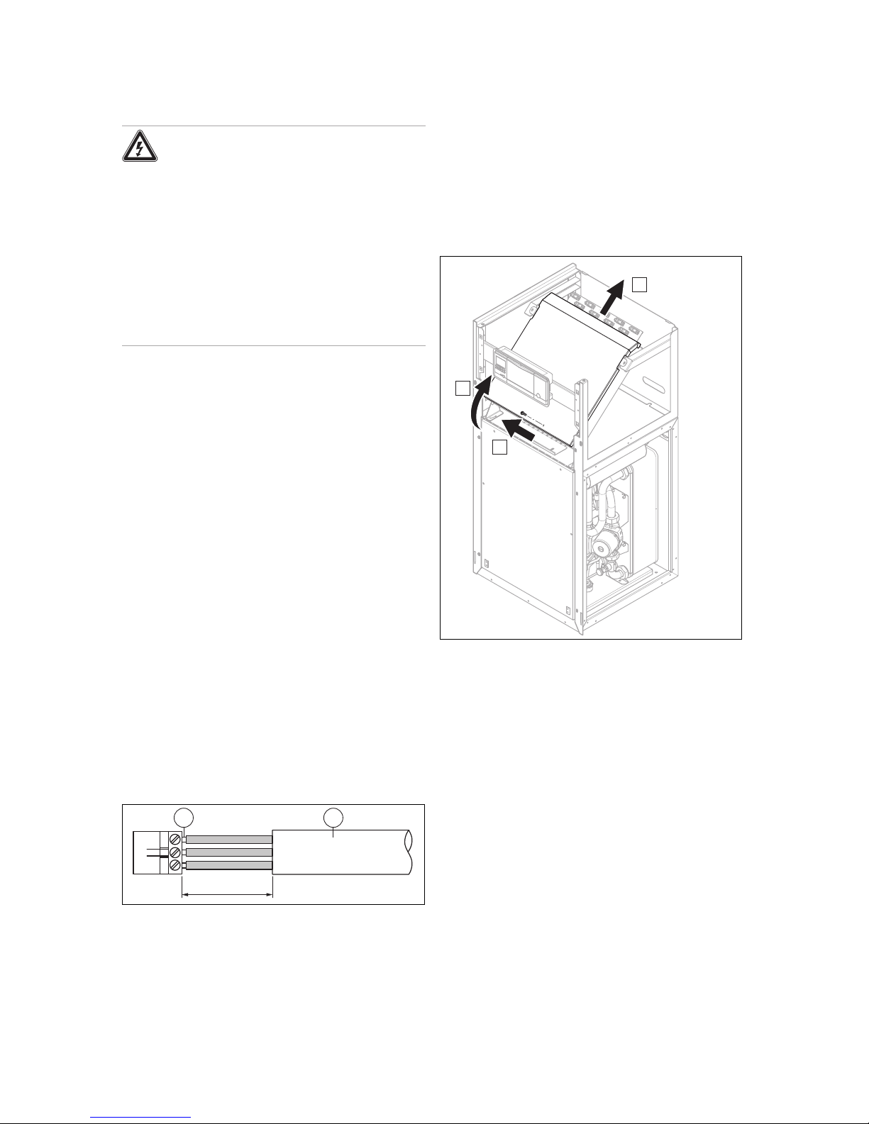
8.12.1 Fitting the casing
1. Fit the side casings and screw in the screws.
2. Place the casing top on the side casings and slide it
back into the recesses provided for this in the back wall.
3. Hook the upper part of the front casing, using the retaining brackets, into the recesses in the side casings and
lower it down.
4. Hook the lower part of the front casing, using the retaining brackets, into the recesses in the side casings and
fold it up.
5. Install the panel on the operator control panel.
6. Attach the operator control panel cover and check that
the cover can move easily when it is opened from either
side.
8.12.2 Checking the system pressure and leak-
tightness
1. After completing the installation, carry out a check of
the system.
2. Start up the product in accordance with the relevant
operating instructions.
3. Check the filling pressure of the heating installation and
check for leaks.
Page 29

Start-up 9
0020213395_00 flexoTHERM exclusive Installation and maintenance instructions 29
9 Start-up
9.1 Operating concept
→ Operating instructions
9.2 Starting up the heat pump
▶ Switch on the power supply.
◁ The basic display appears on the display.
Note
In the case of a restart following a loss of
voltage or a shutdown of the power supply,
the current date and time are automatically
reset by the DCF receiver or, if there is no
DCF reception, you must reset these values
yourself.
9.3 Running the installation assistants
The installation assistant is launched when the heat pump is
switched on for the first time.
Menu → Installer level Configuration
▶
Press to confirm that you wish to start the installation
assistant.
◁ All heating, cooling and hot water requests are
blocked whilst the installation assistant is active.
Note
You cannot exit the installation assistant until
the environment circuit type has been set.
▶
To access the next point, confirm by pressing in each
case.
9.3.1 Setting the language
1. To confirm the set language and to avoid unintentionally
changing it, press twice.
Conditions: Unknown language set
▶
Press and hold and at the same time.
▶
Also briefly press
reset
.
▶
Press and hold and until the display shows the
language setting option.
▶ Select the required language.
▶
Press twice to confirm this change.
9.3.2 Setting the environment circuit type
The following environment circuit types can be set:
– Ground/brine
– Air/brine
– Groundwater/brine
9.3.3 Setting the cooling technology
You must set the installed cooling technology.
When using ground/brine as the heat source, active cooling
is limited to a brine output temperature of 40 °C in order to
protect the source/probe borehole. If this temperature is ex-
ceeded (> 40 °C), active cooling mode is switched off. This
limit can only be changed by Vaillant Customer service.
9.3.4 Enabling auxiliary electric heating
On the system controller, you can select whether the auxiliary electric heating is to be used for heating mode, hot water
handling mode or both modes. Set the maximum output for
the auxiliary electric heater at the heat pump's operator control panel here.
▶ Activate the internal auxiliary electric heating with one of
the following output levels.
▶ Make sure that the maximum output of the auxiliary elec-
tric heating does not exceed the power of the fuse protection installed in the domestic electrical system (see
technical data for measuring currents).
Note
Otherwise the domestic circuit breaker may be
triggered later if the output of the heat source
is insufficient and the auxiliary electric heating
(which has a higher output) is switched off.
Output levels for the 230 V auxiliary electric heating (when
connecting one phase; see Appendix A):
– External
– 2.0 kW
– 3.5 kW
– 5.5 kW
Output levels for the 230 V auxiliary electric heating (when
connecting three separate phases; see Appendix B):
– 7 kW
– 9 kW
9.3.5 Purging the building circuit
▶ Start the check programme P.05 in order to purge the
building circuit. (→ Page 33)
9.3.6 Purging the environment circuit
▶ Start the check programme P.06 in order to purge the
environment circuit. (→ Page 33)
Conditions: Air/brine heat source
– Programme duration of approx. 1 hour. In addi-
tion to purging, the programme includes a selftest of the air/brine collector which checks the following points: Phase errors, communication with
outdoor unit, brine pressure, safety cut-out of the
defroster heater, brine pump operation, brine circuit flow rate, fan, sensor faults, temperature balancing, calibration of the heat pump brine sensor,
calibration of the air/brine collector brine sensor,
inversion of brine lines, brine circuit purging function
9.3.7 Telephone number for the competent
person
You can store your telephone number in the appliance
menu.
The operator can display it in the information menu. The
telephone number can be up to 16 digits long and must not
Page 30

10 Adapting the unit to the heating installation
30 Installation and maintenance instructions flexoTHERM exclusive 0020213395_00
contain any spaces. If the telephone number is shorter, end
the entry after the last digit by pressing .
All of the digits to the right will be deleted.
9.3.8 Ending the installation assistant
▶ Once you have run through the installation assistant suc-
cessfully, confirm by pressing .
◁ The installation assistant will close and will not launch
again when the product is next switched on.
9.4 Calling up the installer level
1.
Press and at the same time.
2. Navigate to Menu → Installer level and confirm by
pressing (OK).
3.
Set the value 17 (code) and confirm by pressing .
9.5 Heating mode flow temperature regulation
For economical and fault-free operation of a heat pump, it is
important to regulate the start of the compressor. Using the
energy balance control, it is possible to minimise the number of heat pump start-ups without having to forgo the convenience of a comfortable room environment. As with other
weather-controlled heating controllers, the controller determines a target flow temperature by recording the outside temperature using a heating curve. The energy balance calculation is made on the basis of this target flow temperature
and the actual flow temperature – the difference per minute
is measured and added up:
1 degree minute [°min] = 1 K temperature difference in the
course of 1 minute
The heat pump starts up at a defined heat deficit (under the
menu point Configuration→ Compressor starts at) and
only switches off again when the supplied heat is equal to
the heat deficit. The larger the preset negative numerical
value, the longer the periods for which the compressor operates or does not operate.
As an additional condition, if there is a deviation of more
than 7 K between the actual flow temperature and the target
flow temperature, the compressor is directly switched on and
switched off. The compressor always starts immediately if a
heating demand only just arises from the controller (e.g. due
to a time period or switching the gas-fired boiler operation to
heat pump mode).
Time conditions for compressor operation
The following shall always apply for operation:
– Minimum running time: 3 minutes
– Minimum rest period: 7 minutes
– Minimum time from start to start: 20 minutes
9.6 Calling up statistics
Menu → Installer level → Test menu → Statistics
– You can use this function to call up the statistics for the
heat pump.
9.7 Checking that the product works correctly
1. Start up the product in accordance with the relevant
operating instructions.
2. Navigate to Menu → Installer level → Test menu →
Check programs.
3. Check the heating mode.
4. Check the hot water handling mode.
5. Check the cooling mode.
10 Adapting the unit to the heating
installation
10.1 Setting parameters
The installation assistant is launched when the product is
switched on for the first time. When the installation assistant
is complete, you can further adjust the parameters of the installation assistant, for example, in the Configuration menu.
Menu → Installer level Configuration
10.2 Setting the high-efficiency pumps
10.2.1 Setting the building circuit pump
Automatic mode
At the factory, the nominal flow is automatically achieved by
volume flow regulation. This volume flow regulation allows
for efficient operation of the building circuit pump because
the pump speed is adjusted to the hydraulic resistance of the
system. Vaillant recommends that you retain this setting.
Manual mode
Menu → Installer level → Configuration → Conf. heat.
build. pump
Menu → Installer level → Configuration → Conf. cool.
build. pump
Menu → Installer level → Configuration → Conf. DHW
build. pump
If you do not want to operate the pump in automatic mode,
you can set it to manual mode in the Configuration menu
for different operating modes. The diagrams below show
how setting the pump actuation affects the remaining feed
head at nominal flow for a temperature spread of 5 K on the
heating side.
Setting the maximum differential pressure in the
building circuit
Menu → Installer level → Configuration → Max. remaining
feed head
If the differential pressure in the building circuit is not permitted to exceed a maximum value, this limit can be set in
the Configuration menu within the range of 0.02 to 0.1 MPa
(200 to 1000 mbar).
Page 31

Adapting the unit to the heating installation 10
0020213395_00 flexoTHERM exclusive Installation and maintenance instructions 31
10.2.2 Remaining feed head of building circuit
pump
10.2.2.1 Remaining feed head for VWF 5x/4
building circuit pump at nominal flow
0
100
200
300
400
500
600
700
800
40 50 60 70 80 90 100
B
A
1
2
3
1 Air heat source
2 Ground heat source
3 Groundwater heat
source
A Remaining feed head in
hPa (mbar)
B Pump output in %
10.2.2.2 Remaining feed head for VWF 8x/4
building circuit pump at nominal flow
0
100
200
300
400
500
600
700
800
40 50 60 70 80 90 100
B
A
1
2
3
1 Air heat source
2 Ground heat source
3 Groundwater heat
source
A Remaining feed head in
hPa (mbar)
B Pump output in %
10.2.2.3 Remaining feed head for VWF 11x/4
building circuit pump at nominal flow
0
100
200
300
400
500
600
700
800
40 50 60 70 80 90 100
B
A
1
2
3
1 Air heat source
2 Ground heat source
3 Groundwater heat
source
A Remaining feed head in
hPa (mbar)
B Pump output in %
10.2.3 Setting the environment circuit pump
If the heat source temperature spread lies below 2 K due to
low pressure losses (large pipe cross-sections, small drilling
depth, with air as the heat source: Short distance to the
air/brine collector) in continuous mode, you can adjust the
pump output. The following diagram shows how setting the
pump actuation affects the remaining feed heads at nominal
flows for a heat source temperature spread of 3 K.
The factory setting on the environment circuit pump depends
on the environment circuit type set and the output range.
▶ Navigate to the Menu → Installer level → Configuration
→ Env. pump target val. menu point.
▶ If necessary, change the factory setting and confirm by
pressing .
10.2.4 Remaining feed head of environment circuit
pump
10.2.4.1 Remaining feed head for VWF 5x/4
environment circuit pump at nominal flow
0
100
200
300
400
500
600
700
800
40 50 60 70 80 90 100
B
A
1
2
3
1 Air heat source 2 Ground heat source
Page 32

11 Troubleshooting
32 Installation and maintenance instructions flexoTHERM exclusive 0020213395_00
3 Groundwater heat
source
A Remaining feed head in
hPa (mbar)
B Pump output in %
10.2.4.2 Remaining feed head for VWF 8x/4
environment circuit pump at nominal flow
0
100
200
300
400
500
600
700
800
40 50 60 70 80 90 100
B
A
1
2
3
1 Air heat source
2 Ground heat source
3 Groundwater heat
source
A Remaining feed head in
hPa (mbar)
B Pump output in %
10.2.4.3 Remaining feed head for VWF 11x/4
environment circuit pump at nominal flow
0
100
200
300
400
500
600
700
800
40 50 60 70 80 90 100
B
A
1
2
3
1 Air heat source
2 Ground heat source
3 Groundwater heat
source
A Remaining feed head in
hPa (mbar)
B Pump output in %
10.3 Setting the flow temperature in heating
mode (with no controller connected)
1. Activate manual mode.
– Menu → Installer level → Configuration → Enable
limp home mode
2.
Press ( ).
◁ The display shows the flow temperature in heating
mode.
3. Change the flow temperature in heating mode by press-
ing or .
– Max. heating mode target flow temperature: 75 ℃
4.
Confirm this change by pressing (OK).
10.4 Setting the flow temperature in cooling
mode (with no controller connected)
1. Activate manual mode.
– Menu → Installer level → Configuration → Enable
limp home mode
2.
Press twice.
◁ The display shows the value of the flow temperature
in cooling mode.
3. Change the flow temperature in cooling mode by press-
ing or .
4.
Confirm this change by pressing (OK).
Note
At the factory, the target flow temperature
can be set to between 20 °C and 16 °C in
passive cooling mode.
10.5 Handing the product over to the operator
▶ Explain to the operator how the safety devices work and
where they are located.
▶ Inform the operator how to handle the product.
▶ In particular, draw attention to the safety information
which the operator must follow.
▶ Inform the operator of the necessity to have the product
maintained according to the specified intervals.
▶ Pass all of the instructions and documentation for the
product to the operator for safe-keeping.
11 Troubleshooting
11.1 Displaying the Live Monitor (current
product status)
Menu → Live Monitor
– You can use the Live Monitor to display the current status
of the product.
Status codes – Overview (→ Page 41)
Page 33

Inspection and maintenance 12
0020213395_00 flexoTHERM exclusive Installation and maintenance instructions 33
11.2 Checking fault codes
The display shows a fault code F.xxx. A plain text display
explains the displayed fault code.
Fault codes have priority over all other displays.
Fault codes (→ Page 43)
If multiple faults occur at the same time, the display shows
the corresponding fault codes for two seconds each in sequence.
▶ Rectify the fault.
▶
To restart the product, press
reset
(→ Operating instruc-
tions).
11.3 Querying the fault memory
Menu → Installer level Fault list
The product has a fault memory. You can use this to query
the last ten faults that occurred in chronological order.
If a DCF sensor is connected, the date on which the fault
occurred will also be displayed.
Display views
– The number of faults that have occurred
– The fault currently selected with fault number F.xxx
11.4 Resetting the fault memory
1.
Press (Delete).
2. Confirm that you wish to clear the fault memory by
pressing (Ok).
11.5 Restarting the installation assistant
You can restart the installation assistant any time by calling it
up manually in the menu.
Menu → Installer level → Start inst. assistant
11.6 Using check programmes
Menu → Installer level → Test menu → Check programmes
You can use this function to start check programmes.
Note
If a fault has occurred, the check programmes are
not run.
You can terminate the check programmes by pressing
(Cancel) at any time.
11.7 Carrying out the actuator test
Menu → Installer level → Test menu → Sensor/actuator
test
You can check that the components of the heating installation are functioning correctly using the sensor/actuator test.
You can actuate more than one actuator at a time.
If you do not select anything to change, you can have the
current control values for the actuators and the sensor values displayed.
You can find a list of the sensor characteristics in the appendix.
Characteristic values for the VR 10 external temperature
sensor (→ Page 48)
Characteristic values for internal temperature sensors
(→ Page 49)
Characteristic values for the VRC DCF outdoor temperature
sensor (→ Page 50)
11.8 Auxiliary electric heater circuit breaker
A circuit breaker is used to secure the internal auxiliary electric heater against short circuits. If the circuit breaker has
been triggered, the auxiliary electric heater remains switched
off until the short circuit has been rectified and the circuit
breaker in the electronics box has been manually reset.
11.8.1 Resetting the circuit breaker in the auxiliary
electric heater
1. Check the supply line to the mains connection PCB.
2. Check that the mains connection PCB is working cor-
rectly.
3. Check the supply lines for the auxiliary electric heater.
4. Check that the auxiliary electric heater is working cor-
rectly.
5. Rectify the short circuit.
6. Reset the circuit breaker in the electronics box.
12 Inspection and maintenance
12.1 Inspection and maintenance information
12.1.1 Inspection
The inspection is intended to determine the actual condition
of a product and compare it with the target condition. This is
done by measuring, checking and observing.
12.1.2 Maintenance
Maintenance is required in order to eliminate any deviations
between the actual condition and the target condition. This is
normally done by cleaning, setting and, if necessary, replacing individual components that are subject to wear.
12.2 Procuring spare parts
The original components of the product were also certified
by the manufacturer as part of the declaration of conformity.
If you use other, non-certified or unauthorised parts during
maintenance or repair work, this may void the conformity of
the product and it will therefore no longer comply with the
applicable standards.
We strongly recommend that you use original spare parts
from the manufacturer as this guarantees fault-free and safe
operation of the product. To receive information about the
available original spare parts, contact the contact address
provided on the reverse of these instructions.
▶ If you require spare parts for maintenance or repair
work, use only the spare parts that are permitted for the
product.
Page 34

13 Decommissioning
34 Installation and maintenance instructions flexoTHERM exclusive 0020213395_00
12.3 Inspection and maintenance check-list
The following table shows the inspection and maintenance
work that must be carried out at specific intervals.
No. Work Inspection
(every year,
within 24
months at
the latest)
Maintenance
(every
two
years)
1 Check the general condition
of the product and that it is
leak-tight.
x x
2 Check the pressure in the
heating circuit and, if required, top up the heating
water.
x x
3 Check and clean the dirt
filters in the heating circuit.
x x
4 Check the volume and con-
centration of the brine fluid
and the pressure in the brine
circuit. Top up with brine
fluid if required.
x x
5 Check that the expansion
vessel and the expansion
relief valve in the brine circuit
are working correctly.
x x
6 Check that the expansion
vessel and the expansion
relief valve in the heating
circuit are working correctly.
x x
7 Check for leaks in the brine
and heating circuit, and repair these leaks if necessary.
x x
8 Check that the circuit
breaker in the electronics
box is working correctly.
x x
12.4 Checking and correcting the filling
pressure of the heating installation
If the filling pressure falls below the minimum pressure, a
maintenance message is shown on the display.
– Min. heating circuit pressure: ≥ 0.05 MPa (≥ 0.50 bar)
▶ Top up the heating water in order to start up the heat
pump again; Filling and purging the heating installation
(→ Page 19).
▶ If you notice frequent losses in pressure, determine and
eliminate the cause.
12.5 Checking and correcting the filling
pressure in the brine circuit
If the filling pressure falls below the minimum pressure, the
heat pump is automatically shut down and a maintenance
message is shown on the display.
– Minimum brine fluid pressure: ≥ 0.05 MPa (≥ 0.50 bar)
▶ Top up the brine fluid to start up the heat pump again,
Filling the brine circuit (→ Page 20).
– Min. brine fluid operating pressure: ≥ 0.07 MPa
(≥ 0.70 bar)
▶ If you notice frequent losses in pressure, determine and
eliminate the cause.
12.6 Carrying out a restart and test operation
Warning.
Risk of burns due to hot and cold com-
ponents.
There is a risk of burns from any uninsulated
pipelines and from the auxiliary electric heating.
▶ Before starting up the unit, install any cas-
ing sections that have been removed.
1. Start up the heat pump system.
2. Check that the heat pump system is working without
any problems.
13 Decommissioning
13.1 Temporarily decommissioning the product
1. Use the partition that is installed on-site (e.g. fuses or
power switches) to disconnect the product from the
power supply.
2. Observe the installation site requirements regarding
frost protection. (→ Page 12)
13.2 Decommissioning the product
1. Use the partition that is installed on-site (e.g. fuses or
power switches) to disconnect the product from the
power supply.
2. Drain the product.
3. Dispose of the product and the operating materials in
accordance with the national regulations.
14 Recycling and disposal
Disposing of the packaging
▶ Dispose of the packaging correctly.
Disposing of the product and accessories
▶ Do not dispose of the product or the accessories with
household waste.
▶ Dispose of the product and all accessories correctly.
▶ Observe all relevant regulations.
Page 35

Customer service 15
0020213395_00 flexoTHERM exclusive Installation and maintenance instructions 35
14.1 Disposing of the brine fluid
Danger!
Risk of injury due to chemical burns!
The brine fluid ethylene glycol is harmful to
health.
▶ Avoid contact with the skin and eyes.
▶ Do not inhale or swallow.
▶ Always wear gloves and protective
goggles.
▶ Observe the safety data sheet that ac-
companies the brine fluid.
▶ Ensure that the brine fluid is disposed of in compliance
with local regulations, for example, at an appropriate
waste site or waste incineration plant.
▶ For smaller volumes, contact your local disposal com-
pany.
14.2 Arranging disposal of coolant
The product is filled with R 410 A refrigerant.
▶ Coolant must only be disposed of by a qualified compet-
ent person.
15 Customer service
Applicability: Great Britain
To ensure regular servicing, it is strongly recommended
that arrangements are made for a Maintenance Agreement.
Please contact Vaillant Service Solutions for further details:
Telephone: 0330 100 3461
Page 36

Appendix
36 Installation and maintenance instructions flexoTHERM exclusive 0020213395_00
Appendix
A Power supply 1~/N/PE 230 V (connection diagram 1 = )
101X201X
1~/N/PE 230V 50Hz
1~/N/PE 230B 50Гц
T4
4321
1234
NL
1~/N/PE 230V 50Hz
1~/N/PE 230B 50Гц
N
N
L
5
6
7
1 Power supply for internal auxiliary electric heating
2 Continuous power supply
X101 Mains connection for compressor
X102 Mains connection for internal auxiliary electric heat-
ing
This is how it is wired when supplied.
In this case, the heat pump is operated using two electricity tariffs (two consumption meters). The X101 connection for the
compressor and electronics is continuously supplied with power. The internal auxiliary electric heating at X102 is supplied
with power via a separate connection, either continuously or with interruptions.
B Power supply 3~/PE 230 V (connection diagram 2 = )
IT
101X201X
2~/PE 230V 50Hz
2~/PE 230B 50Гц
T4
4321
1234
L2L1
3~/PE 230V 50Hz
3~/PE 230B 50Гц
L1
5
6
7
L2
L3
1 Blockable power supply for internal auxiliary electric
heating
2 Blocked power supply for the compressor and con-
trol system
X101 Mains connection for compressor
X102 Mains connection for internal auxiliary electric heat-
ing
In this case, the heat pump is operated using two electricity tariffs (two consumption meters). The X101 connection for the
compressor and electronics is continuously supplied with power. The internal auxiliary electric heating at X102 is supplied
with power via a separate connection, either continuously or with interruptions.
Page 37

Appendix
0020213395_00 flexoTHERM exclusive Installation and maintenance instructions 37
C Installer level overview
Setting level Values Unit Increment, select, ex-
planation
Default setting Setting
Min. Max.
Installer level →
Enter code 00 99 1 (competent person
code 17)
00
Installer level → List of faults →
F.086 – F.1120
1)
Deleting
Installer level → Test menu → Statistics →
Compressor hours Current value h
Compressor starts Current value
Build. pump hours Current value h
Build. pump starts Current value
Environm. pump hours Current value h
Environm. pump starts Current value
4-way valve hours Current value h
4-way valve switch. Current value
Cooling mixer steps Current value
EEV steps, el. expansion valve
steps
Current value
EEV-VI steps, el. expansion
valve injection steps
Current value
VUV DHW switchings Current value
Well pump hours Current value h
Well pump starts Current value
Heat. rod power cons. Current value kWh
Heat. rod switchings Current value
Heat. rod op. hours Current value h
Installer level → Test menu → Check programmes →
P.01 Heating mode Select
P.02 Cooling mode Select
P.03 Hot water handling Select
P.04 Heating rod Select
P.05 Purge building circuit Select
P.06 Purge environment circuit Select
P.07 Purge environment and
building circuit
Select
P.08 Manual defrost Select
Installer level → Test menu → Sensor/actuator test →
Actuators
Building circuit actuators
T.01 Building circuit pump power 0 100 % 5, off Off
T.02 DHW diverter valve Heating Domestic
hot water
Heating, Domestic hot
water
Heating
T.03 Cooling diverter valve (only
for passive cooling)
Heating Cooling Heating, Cooling Heating
1)
See overview of fault codes
Page 38

Appendix
38 Installation and maintenance instructions flexoTHERM exclusive 0020213395_00
Setting level Values Unit Increment, select, ex-
planation
Default setting Setting
Min. Max.
Environment circuit actuators
T.14 Env. circuit pump power 0 100 % 5 0
T.16 Cooling mixer position (only
for passive cooling)
Closes Opens Closes, Stops, Opens Stops
T.17 Well pump Off On Off, On Off
Refrigeration circuit actuators
T.32 4-way valve (only for active
cooling)
Open Closed Open, closed Closed
T.33 Position: EEV 0 100 % 5 0
T.34 Position: EEV-VI 0 100 % 5 0
Further actuators
T.45 Fault outlet Off On Off, On Off
T.46 MPO2 output Off On Off, On Off
T.47 System pump power 0 100 % 5 0
T.48 Circulation pump Off On Off, On Off
T.49 Relay: Cooling active (only
for passive or active cooling)
Off On Off, On Off
Sensors
Building circuit sensors
T.79 Flow temperature −40 90 ℃ 0.1
T.80 Cooling flow temperature
(only for passive cooling)
−40 90 ℃ 0.1
T.81 Return temperature −40 90 ℃ 0.1
T.82 Building circuit: Pressure 0 4.5 bar 0.1
T.83 Building circuit: Flow rate 0 4000 l/h 1
T.84 Lockout contact S20 Open Closed Open, closed Closed
T.85 Safety cut-out heating rod Closed Open Closed, Open Closed
T.86 Cylinder temperature −40 90 ℃ 0.1
Environment circuit sensors
T.97 Environment circuit: Inlet
temperature
−40 90 ℃ 0.1
T.98 Environment circuit: Outlet
temperature
−40 90 ℃ 0.1
T.99 Well inlet temperature (only
for well environment circuit type)
−40 90 ℃ 0.1
T.100 Well outlet temperature
(only for well environment circuit
type)
−40 90 ℃ 0.1
T.101 Environment circuit: Pressure
0 4.5 bar 0.1
T.102 Fault contact: Env. circuit
pump
Closed Open Closed, Open Closed
T.103 Environment circuit:
Pressure monitor (only for
ground/brine environment circuit
type)
Closed Open Closed, Open Closed
Refrigeration circuit sensors
T.121 Compressor outlet temperature
−40 135 ℃ 0.1
T.122 Compressor inlet temperature
−40 90 ℃ 0.1
T.123 EEV-VI inlet temperature −40 90 ℃ 0.1
T.124 EEV-VI outlet temperature −40 90 ℃ 0.1
1)
See overview of fault codes
Page 39

Appendix
0020213395_00 flexoTHERM exclusive Installation and maintenance instructions 39
Setting level Values Unit Increment, select, ex-
planation
Default setting Setting
Min. Max.
T.127 High pressure 0 47 bar (abs) 0.1
T.128 Condensation temperature −40 70 ℃ 0.1
T.129 Low pressure 0 22 bar (abs) 0.1
T.130 Evaporation temperature −40 90 ℃ 0.1
T.131 Superheating target value −40 90 K 0.1
T.132 Superheating actual value −40 90 K 0.1
to 20 K are normal operating parameters
T.134 High-pressure switch Closed Open Closed, Open Closed
T.135 Temperature switch: Compressor outlet
Closed Open Closed, Open Closed
Further sensors
T.146 Outside temperature −40 90 ℃ 0.1
T.147 DCF status Current value No DCF signal
Validate DCF signal
Valid DCF signal
T.148 System temperature −40 90 ℃ 0.1
T.149 MPI input Closed Open Closed, Open Open
Installer level → Configuration →
Language Current language Languages available for
selection
02English
Contact details, Telephone number
Phone number 0 - 9
Compressor starts at −999 0 °min 1 −60
Max. return temp. 30 70 ℃ 1 70
Comp. hysteresis 3 15 1 7
Max. rem. feed head 200 1000 mbar 10 1000
Conf. heat. build. pump Auto 100 % 1 Auto
Conf. cool. build. pump Auto 100 % 1 Auto
Conf. DHW. build. pump Auto 100 % 1 Auto
Reset anti-cycl. time, Anti-cycl.
time after pow. supp. switch-on
0 120 min 10 0
Heat. rod outp. range External 9 kW 230 V
– External
– 2 kW
– 3.5 kW
– 5.5 kW
– 7 kW
– 9 kW
5.5
1)
See overview of fault codes
Page 40

Appendix
40 Installation and maintenance instructions flexoTHERM exclusive 0020213395_00
Setting level Values Unit Increment, select, ex-
planation
Default setting Setting
Min. Max.
Enviro. pump set p. 1 100 % 1 Ground/brine
– VWF 5x/4
230 V: 100
– VWF 8x/4
230 V: 100
– VWF 11x/4
230 V: 100
Well
– VWF 5x/4
230 V: 47
– VWF 8x/4
230 V: 100
– VWF 11x/4
230 V: 100
Freeze protection
Ground/brine:
−14
Well: +2
5 ℃ 1 Ground/brine: -7
Well: +2
Enviro. circuit type Current value Ground/brine
Well
Enable emergency mode Off On Off, On Off
Cooling technology No cool-
ing
On-site
pass.
cooling
No cooling
Active cooling
On-site pass. cooling
On-site pass. cooling
0
Device specific number 40 44 Current value VWF 5x/4 230 V
= 40
VWF 8x/4 230 V
= 41
VWF 11x/4
230 V = 42
Software version Current value for the
controller PCB (HMU
xxxx) and the display
(AI xxxx)
Software version of
the TB mains connection PCB
Software version of
the in-rush current
limiter ICL
Software version of
the first fan unit OMU1
Software version of
the second fan unit
OMU2
xxxx.xx.xx
Installer level → Resets →
Blocking times reset Yes, No No
Statistics reset Yes, No No
Factory settings Yes, No No
Installer level → Start inst. assistant →
Language Languages available for
selection
02English
Enviro. circuit type Select Ground/brine
Well
1)
See overview of fault codes
Page 41

Appendix
0020213395_00 flexoTHERM exclusive Installation and maintenance instructions 41
Setting level Values Unit Increment, select, ex-
planation
Default setting Setting
Min. Max.
Freeze protection
Ground/brine:
−14
Well: +2
5 ℃ 1 Ground/brine: -7
Well: +2
Heat. rod outp. range External 9 kW 1
230 V
– External
– 2 kW
– 3.5 kW
– 5.5 kW
– 7 kW
– 9 kW
5.5
Cooling technology No cool-
ing
On-site
pass.
cooling
No cooling
Active cooling
On-site pass. cooling
On-site pass. cooling
No cooling
Check program: Purge environment and building circuit
Test not
active
Test active
Test not active, Test
active
Test not active
Check program: Purge building
circuit
Test not
active
Test active
Test not active, Test
active
Test not active
Check program: Purge environment circuit
Test not
active
Test active
Test not active, Test
active
Test not active
Contact details, Telephone number
Phone number 0 - 9 Empty
End the installation assistant? Yes, back
1)
See overview of fault codes
D Status codes – Overview
Status code Meaning
Displays relating to the heat pump system
S.34 Heating mode: Frost protection
S.91 Service message: Demo mode
S.100 Standby
S.101 Heating: Compressor switched off
S.102 Heating: Compressor blocked
S.103 Heating: Flow
S.104 Heating: Compressor active
S.107 Heating: Overrun
S.111 Cooling: Compressor shutdown
S.112 Cooling: Compressor blocked
S.113 Cooling: Compressor mode flow
S.114 Cooling: Compressor active
S.117 Cooling: Compressor mode overrun
S.118 Cooling: Flow
S.119 Cooling: Mixer active
S.125 Heating: Heating rod active
S.131 Hot water: Compressor shutdown
S.132 Hot water: Compressor blocked
S.133 Hot water: Flow
S.134 Hot water: Compressor active
S.135 Hot water: Heating rod active
S.137 Hot water: Overrun
Page 42

Appendix
42 Installation and maintenance instructions flexoTHERM exclusive 0020213395_00
Status code Meaning
S.141 Heating: Heating rod shutdown
S.142 Heating: Heating rod blocked
S.151 Hot water: Heating rod shutdown
S.152 Hot water: Heating rod blocked
General displays
S.170 Compressor: Phase failure
S.171 Compressor: Incorrect phase seq.
S.172 Compressor: ICL fault
S.173 Anti-cycling time for the energy supply
company
S.201 Check program: Purging of env. circuit
active
S.202 Check program: Purging of building cir-
cuit active
S.203 Actuator test active
Displays relating to communication
S.211 Connection error: Display not detected
S.212 Connection error: Control not detected
S.215 Connection error: TMB not recognised
S.216 Connection error: ICL not recognised
Displays relating to the environment circuit
S.242 Environment circuit: Outlet temperature
too low
S.246 Environment circuit: Pressure too low
S.247 Env. circuit: Fault contact: Pump open
S.265 Environment circuit: Pressure mon. open
S.266 Environment cir. inlet temperature too
high
Displays relating to the building circuit
S.272 Building circuit: Remaining feed heads
limit active
S.273 Building circuit: Flow temperature too low
S.274 Building circuit: Pressure too low
S.275 Building circuit: Flow rate too low
S.276 Building cir.: Lockout contact S20 opened
S.277 Building circuit: Pump fault
Displays relating to the refrigeration circuit
S.302 High pressure switch opened
S.303 Compressor outlet temperature too high
S.304 Evaporation temperature too low
S.305 Condensation temperature too low
S.306 Evaporation temperature too high
S.308 Condensation temperature too high
S.311 Environment cir. inlet temperature too
low
S.312 Building circuit inlet Return temperature
too low
S.313 Environment cir. inlet temperature too
high
S.314 Building circuit inlet Return temperature
too low
S.240 Oil temperature too low
Displays relating to the auxiliary electric heating circuit
Page 43

Appendix
0020213395_00 flexoTHERM exclusive Installation and maintenance instructions 43
Status code Meaning
S.350 Heating rod: Safety cut-out open
S.351 Heating rod: Flow temp. too high
S.352 Heating rod: Pressure too low
S.353 Heating rod: Flow rate too low
S.354 Heating rod: Phase failure
E Fault codes
Note
In the event of rare faults which are caused by components in the refrigeration circuit, inform Customer Service.
Code Meaning Cause
Remedy
F.070 Invalid Device Specific Number – Replacing the control PCB and
display PCB
– Setting the correct Device Specific
Number
F.086 Building circuit: Lockout contact
S20 open
– Contact S20 on heat pump mains
connection PCB (HMU) open
– Incorrect setting of the limit thermo-
stat
– Flow temperature sensor (heat
pump, gas-fired boiler, system
sensor) measures values that
deviate downwards
– Adjust the maximum flow temperat-
ure for the direct heating circuit via
the system controller (observe the
upper switch-off threshold for the
boilers)
– Adjust the set value for the limit ther-
mostat
– Check the sensor values
F.514 Temp. sensor fault: Compressor
inlet
– Sensor not connected or sensor in-
put has short-circuited
– Check the sensor, and replace if
necessary
– Replace the cable harness
F.517 Temp. sensor fault: Compressor
outlet
– Sensor not connected or sensor in-
put has short-circuited
– Check the sensor, and replace if
necessary
– Replace the cable harness
F.519 Sensor fault: Building circuit re-
turn temp.
– Sensor not connected or sensor in-
put has short-circuited
– Check the sensor, and replace if
necessary
– Replace the cable harness
F.520 Temp. sensor fault: Building cir-
cuit flow
– Sensor not connected or sensor in-
put has short-circuited
– Check the sensor, and replace if
necessary
– Replace the cable harness
F.532 Building circuit: Flow rate too low – Stop cock was not opened
– Building circuit pump defective
– All consumers in the heating system
are closed
– Flow rate is too low for recording
with the volume flow sensor
(< 120 l/h)
– Check the stop cocks and thermo-
static radiator valves
– Ensure that the flow rate is at least
35% of the nominal flow rate
– Check that the building circuit pump
functions correctly
F.546 Sensor fault: High pressure – Sensor not connected or sensor in-
put has short-circuited
– Check the sensor (e.g. using an in-
stallation aid), and replace if necessary
– Replace the cable harness
F.583 Building circuit: Flow temp. too
low
– Four-way valve is mechanically
blocked
– The temperature sensor in the flow is
defective
– Air in the building circuit
– Check the building circuit flow rate
– Check the quality of the plug contact
on the PCB and on the cable harness
– Check that the sensor is working
correctly (measure resistance using
sensor characteristic values)
– Replace the sensor
– Purging the building circuit
F.685 Connection error: Control not de-
tected
– System controller was previously de-
tected but the connection is broken
– Check the eBUS connection to the
system controller
F.701 Temp. sensor fault: Environ. cir-
cuit inlet
– Sensor not connected or sensor in-
put has short-circuited
– Check the sensor, and replace if
necessary
– Replace the cable harness
Page 44

Appendix
44 Installation and maintenance instructions flexoTHERM exclusive 0020213395_00
Code Meaning Cause
Remedy
F.702 Temp. sensor fault: Environment
cir. out
– Sensor not connected or sensor in-
put has short-circuited
– Check the sensor, and replace if
necessary
– Replace the cable harness
F.703 Sensor fault: Low pressure – Sensor not connected or sensor in-
put has short-circuited
– Check the sensor, and replace if
necessary
– Replace the cable harness
F.704 Sensor fault: Building cir. pres-
sure
– Sensor not connected or sensor in-
put has short-circuited
– Check the sensor, and replace if
necessary
– Replace the cable harness
F.705 Sensor fault: Enviro. cir. pressure – Sensor not connected or sensor in-
put has short-circuited
– Check the sensor, and replace if
necessary
– Replace the cable harness
F.707 Connection error: Display not de-
tected
– Cable not connected or connected
incorrectly
Operator control panel display defective
– Check the connection line between
the mains connection PCB and the
display
– Replace the display
F.710 Environment circuit: Outlet tem-
perature too low
– Environment circuit pump defective
– Temperature sensor for environment
circuit outlet defective
– Volume flow too low in the environ-
ment circuit
– Air in the environment circuit
– Check the flow rate in the environ-
ment circuit
– Check the quality of the plug contact
on the PCB and on the cable harness
– Check that the sensor is working
correctly (measure resistance using
sensor characteristic values)
– Replace the sensor
– Check the volume flow of the en-
vironment circuit pump (optimum
spread of 3 K)
– Purging the environment circuit
F.714 Environment circuit: Pressure too
low
– Pressure loss in the environment
circuit due to leaks or air pockets
– Environment circuit pressure sensor
defective
– Check the environment circuit for
leaks
– Top up the medium (brine/water),
purge
– Check the quality of the plug contact
on the PCB and on the cable harness
– Check that the pressure sensor is
working correctly
– Replace the pressure sensor
F.715 Env. circuit: Fault contact: Pump
open
– The electronics system of the high-
efficiency pump has detected a fault
(e. g. dry running, blockage, overvoltage, undervoltage) and switched
the pump off as a securing measure.
– Switch the heat pump off for at least
30 seconds (no current)
– Check the quality of the plug contact
on the PCB
– Check that the pump functions cor-
rectly
– Purging the environment circuit
F.718 Fan unit 1: Fan blocked – There is no confirmation signal stat-
ing that the fan is rotating
– Check the air route and, if required,
remove any blockages
– Check and, if required, replace the
F1 fuse on the PCB in the fan unit
(OMU)
F.719 Fan unit 1: Safety cut-out open – The safety cut-out on the de-icer is
open due to insufficient volume flow
and/or brine temperatures above
70 °C
– When operating the de-icer outside
of the permitted area of application
– De-icer operation when the brine
circuit is not filled
– De-icer operation at brine tem-
peratures above 120 °C trips the
fuse of the safety cut-out and requires that the fuse be replaced
– Check for circulation in the environ-
ment circuit pump
– If required, open the stop cock
The safety cut-out is automatically reset
as soon as the temperature at the fuse
falls below 55 °C again.
If the safety cut-out is still open at a deicer temperature below 55 °C, temperatures above 120 °C were reached and
the fuse tripped.
– Check and, if required, replace the
F1 fuse of the air/brine collector
– Replace the safety cut-out
Page 45

Appendix
0020213395_00 flexoTHERM exclusive Installation and maintenance instructions 45
Code Meaning Cause
Remedy
F.723 Building circuit: Pressure too low – Pressure loss in the building circuit
due to leaks or air pockets
– Building circuit pressure sensor de-
fective
– Check the building circuit for leaks
– Top up with water, purge
– Check the quality of the plug contact
on the PCB and on the cable harness
– Check that the pressure sensor is
working correctly
– Replace the pressure sensor
F.724 Sensor fault: Fan unit 1 fan inlet
temp.
– Sensor not connected or sensor in-
put has short-circuited
– Check the sensor in the fan unit, and
replace if necessary
– Replace the cable harness in the fan
unit
F.725 Sensor fault: Fan unit 1 brine flow
temp.
F.731 High pressure switch opened – Coolant pressure too high. The in-
tegrated high-pressure switch has
tripped at 46 bar (g) or 47 bar (abs)
– Insufficient energy output via the
relevant condenser
– Purging the building circuit
– Insufficient volume flow as a result of
closing individual room controllers in
an underfloor heating system
– Check that the dirt filter that is in
place is permeable
– Refrigerant flow rate too low (e.g.
electronic expansion valve defective,
four-way valve mechanically blocked,
filter blocked). Inform Customer Service.
– VWL SA (cooling mode): Check the
fan unit for dirt
F.732 Compressor outlet temperature
too high
The compressor outlet temperature is
above 130 °C:
– Application limits exceeded
– EEV does not work or does not open
correctly
– Coolant volume too low
– Check the low-pressure sensor,
compressor inlet sensor and outlet
sensor
– Check the EEV (does the EEV
move to the limit stop? Use the
sensor/actuator test)
– Check the refrigerant volume (see
Technical data)
– Carry out a leak-tightness test
F.733 Evaporation temperature too low – No flow rate in the environment cir-
cuit (heating mode)
– Energy input too low in the environ-
ment circuit (heating mode) or building circuit (cooling mode)
– Check the flow rate in the environ-
ment circuit
– Check the dimensioning of the en-
vironment circuit (heating mode) for
ground/brine and groundwater/brine
– If the building circuit contains ther-
mostatic radiator valves, check that
they are suitable for cooling mode
(cooling mode)
– VWL_SA (heating mode)
– Check the fan unit for dirt
– Check the EEV (does the EEV
move to the limit stop? Use the
sensor/actuator test)
– Check the low-pressure sensor and
compressor inlet sensor
F.734 Condensation temperature too low – Temperature in the building circuit
(heating mode) or environment circuit (cooling mode) too low for compressor operation
– Coolant volume too low
– Check the EEV (does the EEV
move to the limit stop? Use the
sensor/actuator test)
– Check the compressor inlet sensor,
high-pressure sensor and low-pressure sensor
– Check the refrigerant volume (see
Technical data)
– Leak-tightness test
Page 46

Appendix
46 Installation and maintenance instructions flexoTHERM exclusive 0020213395_00
Code Meaning Cause
Remedy
F.735 Evaporation temperature too high – Temperature in the environment cir-
cuit (heating mode) or building circuit (cooling mode) too high for compressor operation
– Feeding of external heat into the
environment circuit
– Reduce or stop the external heat
that is entering
– Check the de-icer (does it heat
up even though it is Off in the
sensor/actuator test?)
– Check the EEV (does the EEV
move to the limit stop? Use the
sensor/actuator test)
– Check the compressor inlet sensor
and low-pressure sensor
F.737 Condensation temperature too
high
– Temperature in the building circuit
(heating mode) or environment circuit (cooling mode) too high for compressor operation
– Coolant volume too high
– Check the EEV (does the EEV
move to the limit stop? Use the
sensor/actuator test)
– Check the compressor inlet sensor,
high-pressure sensor and low-pressure sensor
– Check the refrigerant volume (see
Technical data)
F.740 Environment cir. inlet temperature
too low
– Inlet temperature in the environment
circuit too low for the compressor to
start for heating:
– Air/brine: Environment circuit inlet
temperature < -28 °C
– Ground/brine: Environment circuit
inlet temperature < -7 °C
– Groundwater/brine: Groundwater
inlet temperature < 2 °C
– Check the dimensioning of the envir-
onment circuit
– Check the sensors
F.741 Building circuit inlet Return tem-
perature too low
– Return temperature in the building
circuit too low for the compressor to
start
Heating:
– Return temperature < 5 °C
Cooling:
– Return temperature < 10 °C
– Heating: Check that the four-way
valve functions correctly
F.742 Environment cir. inlet temperature
too high
– Inlet temperature in the environment
circuit too high for the compressor to
start
– Brine inlet temperature > 50 °C
– Feeding of external heat into the
environment circuit
– Heating: Check that the four-way
valve functions correctly
– Check the environment circuit
– Check the sensors
– Reduce or stop the external heat
that is entering
F.743 Building circuit inlet Return tem-
perature too high
– Return temperature in the building
circuit too high for the compressor to
start
Heating:
– Return temperature > 55 °C to 60 °C
(depending on the brine inlet temperature)
Cooling:
– Return temperature > 35 °C
– Cooling: Check that the four-way
valve functions correctly
– Check the sensors
F.783 Connection error: Terminal block
(TMB)
Cable not connected or connected incorrectly
Check the connection line between the
mains connection PCB and the controller
PCB
F.784 Connection error: ICL Cable not connected or connected incor-
rectly
Check the connection line between the
mains connection PCB and the in-rush
current limiter PCB
Page 47

Appendix
0020213395_00 flexoTHERM exclusive Installation and maintenance instructions 47
Code Meaning Cause
Remedy
F.787 Environment circuit: Pressure
mon. open
– Pressure loss in the environment
circuit due to leaks or air pockets
– Environment circuit pressure monitor
defective
– Check the environment circuit for
leaks
– Top up the medium (brine/water),
purge
– Check the screwed contact on the
PCB
– Check that the pressure monitor
works correctly
– Replace the pressure monitor
F.788 Building circuit: Pump fault – The electronics system of the high-
efficiency pump has detected a fault
(e. g. dry running, blockage, overvoltage, undervoltage) and switched
the pump off as a securing measure.
– Switch the heat pump off for at least
30 seconds (no current)
– Check the quality of the plug contact
on the PCB
– Check that the pump functions cor-
rectly
– Purging the building circuit
F.792 Sensor fault: VI inlet temp. – Sensor not connected or sensor in-
put has short-circuited
– Check the sensor, and replace if
necessary
– Replace the cable harness
F.793 Sensor fault: EEV-VI outlet temp. – Sensor not connected or sensor in-
put has short-circuited
– Check the sensor, and replace if
necessary
– Replace the cable harness
F.797 Sensor fault: Cooling flow temp. – Sensor not connected or sensor in-
put has short-circuited
– Check the sensor, and replace if
necessary
– Replace the cable harness
F.798 Sensor fault: Well inlet temp. – Sensor not connected or sensor in-
put has short-circuited
– Check the sensor, and replace if
necessary
– Replace the cable harness
F.799 Sensor fault: Well outlet temp. – Sensor not connected or sensor in-
put has short-circuited
– Check the sensor, and replace if
necessary
– Replace the cable harness
F.1100 Heating rod: Safety cut-out open The safety cut-out on the auxiliary elec-
tric heater is open due to:
– Insufficient volume flow or air in the
building circuit
– Heating rod operation when the
building circuit is not filled
– Heating rod operation at flow tem-
peratures above 110 °C trips the
fuse of the safety cut-out and requires that the fuse be replaced
– Feeding of external heat into the
building circuit
– Check the circulation in the building
circuit pump
– If required, open the stop cock. The
safety cut-out is automatically reset
as soon as the temperature at the
fuse falls below 55 °C again.
Also press
reset
.
If the safety cut-out is still open at an
auxiliary electric heater temperature
below 55 °C, temperatures above
110 °C were reached and the fuse
tripped.
– Replace the safety cut-out
– Reduce or stop the external heat
that is entering
F.1117 Compressor: Phase failure – In-rush current limiter defective or
incorrectly connected
– Defective fuse
– Poorly tightened electrical connec-
tions
– Mains voltage too low
– Compressor/low tariff power supply
not connected
– Blocked by energy supply company
for over three hours
– Check the fuse
– Check the electrical connections
– Measure voltage at the heat pump
electrical connection
– Reduce energy supply company
anti-cycling time to under three hours
F.1118 Compressor: Incorrect phase seq. – Incorrect order of phase connection
to the mains supply
– In-rush current limiter defective or
incorrectly connected
– Change the phase order by switch-
ing over two phases at a time on the
mains supply
– Check the in-rush current limiter
Page 48

Appendix
48 Installation and maintenance instructions flexoTHERM exclusive 0020213395_00
Code Meaning Cause
Remedy
F.1119 Compressor: ICL fault – In-rush current limiter defective or
incorrectly connected
– Mains voltage too low
– Check all plug contacts
– Checking the ICL compressor con-
nection
– Check the ICL controller PCB con-
nection
– Replace the ICL
F.1120 Heating rod: Phase failure – The circuit breaker in the electronics
box has been triggered.
– Auxiliary electric heater defective
– Poorly tightened electrical connec-
tions
– Mains voltage too low
– Blocked by energy supply company
for over five hours
– Check the auxiliary electric heater
and its power supply, and reset the
circuit breaker
– Check the electrical connections
– Measure the voltage at the electrical
connection for the auxiliary electric
heater
F Characteristic values for the VR 10 external temperature sensor
Temperature (°C) Resistance (ohms)
-40 87879
-35 63774
-30 46747
-25 34599
-20 25848
-15 19484
-10 14814
-5 11358
0 8778
5 6836
10 5363
15 4238
20 3372
25 2700
30 2176
35 1764
40 1439
45 1180
50 973
55 807
60 672
65 562
70 473
75 400
80 339
85 289
90 247
95 212
100 183
105 158
110 137
115 120
120 104
125 92
Page 49

Appendix
0020213395_00 flexoTHERM exclusive Installation and maintenance instructions 49
Temperature (°C) Resistance (ohms)
130 81
135 71
140 63
145 56
150 50
155 44
G Characteristic values for internal temperature sensors
Temperature (°C) Resistance (ohms)
-40 327344
-35 237193
-30 173657
-25 128410
-20 95862
-15 72222
-10 54892
-5 42073
0 32510
5 25316
10 19862
15 15694
20 12486
25 10000
30 8060
35 6535
40 5330
45 4372
50 3605
55 2989
60 2490
65 2084
70 1753
75 1481
80 1256
85 1070
90 916
95 786
100 678
105 586
110 509
115 443
120 387
125 339
130 298
135 263
140 232
145 206
150 183
Page 50

Appendix
50 Installation and maintenance instructions flexoTHERM exclusive 0020213395_00
H Characteristic values for the VRC DCF outdoor temperature sensor
Temperature (°C) Resistance (ohms)
-25 2167
-20 2067
-15 1976
-10 1862
-5 1745
0 1619
5 1494
10 1387
15 1246
20 1128
25 1020
30 920
35 831
40 740
Page 51

Appendix
0020213395_00 flexoTHERM exclusive Installation and maintenance instructions 51
I Heat pump schematic
HG1
AB
B
A
CP1
V2
HE2
HE1
C1
HE4
TCE
V5
TT 11
TZ 11
PZ 11
PT 11
TT 14
TT 10
PT 10
TT 17
TT 30
PT 30
TT 31
TT 20
PT 20
TT 21
TZ 21
M
C
S
E
D
V7
TCE
CP2
1 32 4
5
6
FLT1
FLT2
1 Heating circuit diaphragm expansion tank connec-
tion
2 Circulation connection
3 Heating return
4 Heating flow
5 Hot brine
6 Cold brine
C1 Compressor
CP1 Heating pump
CP2 Brine pump
FLT1 Filter
FLT2 Filter
HE1 Condenser
Page 52

Appendix
52 Installation and maintenance instructions flexoTHERM exclusive 0020213395_00
HE2 Evaporator
HE4 Evaporator for intermediate injection
HG1 Auxiliary electric heater
PT10 Low-pressure sensor
PT11 High-pressure sensor
PT20 Heating circuit pressure sensor
PT30 Brine pressure sensor
PZ11 High-pressure switch
TT10 Compressor inlet temperature sensor
TT11 Compressor outlet temperature sensor
TT14 Intermediate injection compressor inlet temperature
sensor
TT17 Electronic expansion valve outlet temperature
sensor
TT20 Heating return temperature sensor
TT21 Heating flow temperature sensor
TT30 Source inlet temperature sensor
TT31 Source outlet temperature sensor
TZ11 Compressor outlet temperature switch
TZ21 Safety cut-out temperature switch
V1 Electronic expansion valve
V2 3-way valve for hot water
V5 Electronic expansion valve for intermediate injection
V7 4-2-way valve
Page 53

Appendix
0020213395_00 flexoTHERM exclusive Installation and maintenance instructions 53
J Commissioning Checklist
Applicability: Great Britain
© Heating and Hotwater Industry Council (HHIC)
www.centralheating.co.uk
Benchmark Commissioning and
Servicing Section
It is a requirement that the boiler is installed and commissioned to the
completed in full.
Page 54

Appendix
54 Installation and maintenance instructions flexoTHERM exclusive 0020213395_00
This Commissioning Checklist is to be completed in full by the competent person who commissioned the heat pump and associated
equipment as a means of demonstrating compliance with the appropriate Building Regulations and then handed to the customer to keep for
future reference.
Failure to install and commission this equipment to the manufacturer’s instructions may invalidate the warranty but does not affect statutory rights.
AIR TO WATER HEAT PUMP COMMISSIONING CHECKLIST
Customer name: Telephone number:
Address:
Heat Pump Make and Model
Heat Pump Serial Number
Commissioned by (PRINT NAME): &HUWL¿HG2SHUDWLYH5HJ1R>@
Company name: Telephone number:
Company address:
Commissioning date:
%XLOGLQJ5HJXODWLRQV1RWL¿FDWLRQ1XPEHULIDSSOLFDEOH>@
CONTROLS - SYSTEM AND HEAT PUMP (tick the appropriate boxes)
Time and temperature control to heating
Room thermostat and programmer/timer Programmable Roomstat
Load/weather compensation 2SWLPXPVWDUWFRQWURO
Time and temperature control to hot water Cylinder thermostat and programmer/timer Combined with Heat pump main controls
+HDWLQJ]RQHYDOYHVLQFOXGLQJXQGHUÀRRUORRSV Fitted Not required
Hot water zone valves Fitted Not required
Thermostatic radiator valves Fitted Not required
+HDW3XPS6DIHW\,QWHUORFN>@ Built In Provided
2XWGRRU6HQVRU Fitted Not required
Automatic bypass to system Fitted Not required
Buffer Vessel Fitted Yes No If YES Volume: Litres
ALL SYSTEMS
7KHKHDWLQJV\VWHPKDVEHHQ¿OOHGDQGSUHVVXUHWHVWHG Yes
([SDQVLRQYHVVHOIRUKHDWLQJLVVL]HG¿WWHGFKDUJHGLQDFFRUGDQFHZLWKPDQXIDFWXUHU¶VLQVWUXFWLRQV Yes
7KHKHDWSXPSLV¿WWHGRQDVROLGVWDEOHVXUIDFHFDSDEOHRIWDNLQJLWVZHLJKW Yes
7KHV\VWHPKDVEHHQÀXVKHGDQGFOHDQHGLQDFFRUGDQFHZLWK%6DQGKHDWSXPSPDQXIDFWXUHU¶VLQVWUXFWLRQV Yes
What system cleaner was used?
What inhibitor was used? Quantity litres
Is the system adequately frost protected? Yes
OUTDOOR UNIT
Are all external pipeworks insulated? Yes
Is the fan free from obstacles and operational? Yes
Has suitable consideration been made for waste water discharge? Yes
CENTRAL HEATING MODE
Heating Flow Temperature °C Heating Return Temperature °C
DOMESTIC HOT WATER MODE Measure and Record:
Is the heat pump connected to a hot water cylinder? Unvented Vented Thermal Store Not Connected
Hot water has been checked at all outlets Yes +DYH7KHUPRVWDWLF%OHQGLQJ9DOYHVEHHQ¿WWHG" Yes Not required
ADDITIONAL SYSTEM INFORMATON
Additional heat sources connected: Gas Boiler 2LO%RLOHU Electric Heater Solar Thermal 2WKHU
ALL INSTALLATIONS
The heating, hot water and ventilation systems complies with the appropriate Building Regulations Yes
All electrical work complies with the appropriate Regulations Yes
The heat pump and associated products have been installed and commissioned in accordance with the manufacturer’s instructions Yes
The operation of the heat pump and system controls have been demonstrated to the customer Yes
The manufacturer’s literature, including Benchmark Checklist and Service Record, has been explained and left with the customer Yes
Commissioning Engineer’s Signature
Customer’s Signature
7RFRQ¿UPVDWLVIDFWRU\GHPRQVWUDWLRQDQGUHFHLSWRIPDQXIDFWXUHU¶VOLWHUDWXUH
1RWHV>@,QVWDOOHUVVKRXOGEHPHPEHUVRIDQDSSURSULDWH&RPSHWHQW3HUVRQV6FKHPH>@$OOLQVWDOODWLRQVLQ(QJODQGDQG
:DOHVPXVWEHQRWL¿HGWR/RFDO$UHD%XLOGLQJ&RQWURO/$%&HLWKHUGLUHFWO\RUWKURXJKD&RPSHWHQW3HUVRQV6FKHPH$
%XLOGLQJ5HJXODWLRQV&RPSOLDQFH&HUWL¿FDWHZLOOWKHQEHLVVXHGWRWKHFXVWRPHU>@0D\EHUHTXLUHGIRUV\VWHPVFRYHUHG
E\*5HJXODWLRQV
© Heating and Hotwater Industry Council (HHIC)
www.centralheating.co.uk
Page 55

Appendix
0020213395_00 flexoTHERM exclusive Installation and maintenance instructions 55
It is recommended that your heating system is serviced regularly and that the appropriate Service Interval Record is completed.
Service Provider
Before completing the appropriate Service Record below, please ensure you have carried out the service as described in the manufacturer’s instructions.
$OZD\VXVHWKHPDQXIDFWXUHU¶VVSHFL¿HGVSDUHSDUWZKHQUHSODFLQJFRQWUROV
SERVICE RECORD
SERVICE 01
Date:
Engineer name:
Company name:
Telephone No:
2SHUDWLYH,'1R
Comments:
Signature
SERVICE 03
Date:
Engineer name:
Company name:
Telephone No:
2SHUDWLYH,'1R
Comments:
Signature
SERVICE 05
Date:
Engineer name:
Company name:
Telephone No:
2SHUDWLYH,'1R
Comments:
Signature
SERVICE 07
Date:
Engineer name:
Company name:
Telephone No:
2SHUDWLYH,'1R
Comments:
Signature
SERVICE 09
Date:
Engineer name:
Company name:
Telephone No:
2SHUDWLYH,'1R
Comments:
Signature
SERVICE 02
Date:
Engineer name:
Company name:
Telephone No:
2SHUDWLYH,'1R
Comments:
Signature
SERVICE 04
Date:
Engineer name:
Company name:
Telephone No:
2SHUDWLYH,'1R
Comments:
Signature
SERVICE 06
Date:
Engineer name:
Company name:
Telephone No:
2SHUDWLYH,'1R
Comments:
Signature
SERVICE 08
Date:
Engineer name:
Company name:
Telephone No:
2SHUDWLYH,'1R
Comments:
Signature
SERVICE 10
Date:
Engineer name:
Company name:
Telephone No:
2SHUDWLYH,'1R
Comments:
Signature
Page 56

Appendix
56 Installation and maintenance instructions flexoTHERM exclusive 0020213395_00
K Commissioning Checklist
Applicability: Great Britain
© Heating and Hotwater Industry Council (HHIC)
www.centralheating.co.uk
Benchmark Commissioning and
Servicing Section
It is a requirement that the boiler is installed and commissioned to the
completed in full.
Page 57

Appendix
0020213395_00 flexoTHERM exclusive Installation and maintenance instructions 57
This Commissioning Checklist is to be completed in full by the competent person who commissioned the heat pump and associated
equipment as a means of demonstrating compliance with the appropriate Building Regulations and then handed to the customer to keep for
future reference.
Failure to install and commission this equipment to the manufacturer’s instructions may invalidate the warranty but does not affect statutory rights.
GROUND SOURCE HEAT PUMP COMMISSIONING CHECKLIST
Customer name: Telephone number:
Address:
Heat Pump Make and Model
Heat Pump Serial Number
Commissioned by (PRINT NAME): &HUWL¿HG2SHUDWLYH5HJ1R>@
Company name: Telephone number:
Company address:
Commissioning date:
%XLOGLQJ5HJXODWLRQV1RWL¿FDWLRQ1XPEHULIDSSOLFDEOH>@
CONTROLS - SYSTEM AND HEAT PUMP (tick the appropriate boxes)
Time and temperature control to heating
Room thermostat and programmer/timer Programmable Roomstat
Load/weather compensation 2SWLPXPVWDUWFRQWURO
Time and temperature control to hot water Cylinder thermostat and programmer/timer Combined with Heat pump main controls
+HDWLQJ]RQHYDOYHVLQFOXGLQJXQGHUÀRRUORRSV Fitted Not required
Hot water zone valves Fitted Not required
Thermostatic radiator valves Fitted Not required
+HDW3XPS6DIHW\,QWHUORFN>@ Built In Provided
2XWGRRU6HQVRU Fitted Not required
Automatic bypass to system Fitted Not required
Buffer Vessel Fitted Yes No If YES Volume: Litres
ALL SYSTEMS
7KHKHDWLQJV\VWHPKDVEHHQ¿OOHGDQGSUHVVXUHWHVWHG Yes
([SDQVLRQYHVVHOIRUKHDWLQJLVVL]HG¿WWHGFKDUJHGLQDFFRUGDQFHZLWKPDQXIDFWXUHU¶VLQVWUXFWLRQV Yes
7KHKHDWSXPSLV¿WWHGRQDVROLGVWDEOHVXUIDFHFDSDEOHRIWDNLQJLWVZHLJKW Yes
7KHV\VWHPKDVEHHQÀXVKHGDQGFOHDQHGLQDFFRUGDQFHZLWK%6DQGKHDWSXPSPDQXIDFWXUHU¶VLQVWUXFWLRQV Yes
What system cleaner was used?
What inhibitor was used? Quantity litres
Are all exposed external pipeworks insulated? Yes
BORE HOLE/GROUND LOOPS
Bore Hole Ground Loop Length/Depth m
7KHJURXQGORRSVERUHKROHSLSHVKDYHEHHQ¿OOHGDQGSUHVVXUHWHVWHGLQDFFRUGDQFHZLWKUHOHYDQW%ULWLVK6WDQGDUGV Yes
,IPRUHWKDQRQHFROOHFWRUKDVEHHQXVHGKDVWKHV\VWHPEHHQK\GUDXOLFDOO\EDODQFHG)ORZEDODQFLQJUHJXODWLQJYDOYHV¿WWHGDGMXVWHG" Yes
Has the system been vented/de-aired? Yes
$UHV\VWHP¿OWHUV¿WWHGFOHDQ" Yes
Is the system topped up to the correct level? Yes
:DVWKHV\VWHPFOHDQHGÀXVKHGSULRUWRXVH" Yes
Are isolating valves in their correct position Yes
What system cleaner was used? Qty litres
What antifreeze was used? Qty litres
What temperature will the antifreeze protect to? °C
What inhibitor was used (if not included in Antifreeze)? Qty litres
5HFRUGLQFRPLQJFROOHFWRUÀXLGWHPSHUDWXUH °C
5HFRUGRXWJRLQJFROOHFWRUÀXLGWHPSHUDWXUH °C
CENTRAL HEATING MODE Measure and Record
Heating Flow Temperature °C Heating Return Temperature °C
DOMESTIC HOT WATER MODE Measure and Record:
Is the heat pump connected to a hot water cylinder? Unvented Vented Thermal Store Not Connected
Hot water has been checked at all outlets Yes +DYH7KHUPRVWDWLF%OHQGLQJ9DOYHVEHHQ¿WWHG" Yes Not required
ADDITIONAL SYSTEM INFORMATON
Additional heat sources connected: Gas Boiler 2LO%RLOHU Electric Heater Solar Thermal 2WKHU
ALL INSTALLATIONS
The heating, hot water and ventilation systems complies with the appropriate Building Regulations Yes
All electrical work complies with the appropriate Regulations
The heat pump and associated products have been installed and commissioned in accordance with the manufacturer’s instructions Yes
The operation of the heat pump and system controls have been demonstrated to the customer Yes
The manufacturer’s literature, including Benchmark Checklist and Service Record, has been explained and left with the customer Yes
Commissioning Engineer’s Signature
Customer’s Signature
7RFRQ¿UPVDWLVIDFWRU\GHPRQVWUDWLRQDQGUHFHLSWRIPDQXIDFWXUHU¶VOLWHUDWXUH
1RWHV>@,QVWDOOHUVVKRXOGEHPHPEHUVRIDQDSSURSULDWH&RPSHWHQW3HUVRQV6FKHPH>@$OOLQVWDOODWLRQVLQ(QJODQGDQG
:DOHVPXVWEHQRWL¿HGWR/RFDO$UHD%XLOGLQJ&RQWURO/$%&HLWKHUGLUHFWO\RUWKURXJKD&RPSHWHQW3HUVRQV6FKHPH$
%XLOGLQJ5HJXODWLRQV&RPSOLDQFH&HUWL¿FDWHZLOOWKHQEHLVVXHGWRWKHFXVWRPHU>@0D\EHUHTXLUHGIRUV\VWHPVFRYHUHG
E\*5HJXODWLRQV
© Heating and Hotwater Industry Council (HHIC)
www.centralheating.co.uk
Page 58

Appendix
58 Installation and maintenance instructions flexoTHERM exclusive 0020213395_00
It is recommended that your heating system is serviced regularly and that the appropriate Service Interval Record is completed.
Service Provider
Before completing the appropriate Service Interval Record below, please ensure you have carried out the service as described in the manufacturer’s
LQVWUXFWLRQV$OZD\VXVHWKHPDQXIDFWXUHU¶VVSHFL¿HGVSDUHSDUWZKHQUHSODFLQJFRQWUROV
SERVICE RECORD
SERVICE 01
Date:
Engineer name:
Company name:
Telephone No:
2SHUDWLYH,'1R
Comments:
Signature
SERVICE 03
Date:
Engineer name:
Company name:
Telephone No:
2SHUDWLYH,'1R
Comments:
Signature
SERVICE 05
Date:
Engineer name:
Company name:
Telephone No:
2SHUDWLYH,'1R
Comments:
Signature
SERVICE 07
Date:
Engineer name:
Company name:
Telephone No:
2SHUDWLYH,'1R
Comments:
Signature
SERVICE 09
Date:
Engineer name:
Company name:
Telephone No:
2SHUDWLYH,'1R
Comments:
Signature
SERVICE 02
Date:
Engineer name:
Company name:
Telephone No:
2SHUDWLYH,'1R
Comments:
Signature
SERVICE 04
Date:
Engineer name:
Company name:
Telephone No:
2SHUDWLYH,'1R
Comments:
Signature
SERVICE 06
Date:
Engineer name:
Company name:
Telephone No:
2SHUDWLYH,'1R
Comments:
Signature
SERVICE 08
Date:
Engineer name:
Company name:
Telephone No:
2SHUDWLYH,'1R
Comments:
Signature
SERVICE 10
Date:
Engineer name:
Company name:
Telephone No:
2SHUDWLYH,'1R
Comments:
Signature
Page 59

Appendix
0020213395_00 flexoTHERM exclusive Installation and maintenance instructions 59
L Technical data
L.1 General
Dimensions
VWF 57/4 230 V VWF 87/4 230 V VWF 117/4 230 V
Product dimensions, height, without adjustable feet
1,183 mm 1,183 mm 1,183 mm
Product dimensions, width
595 mm 595 mm 595 mm
Product dimensions, depth
600 mm 600 mm 600 mm
Weight, with packaging
161 kg 176 kg 188 kg
Weight, without packaging
151 kg 166 kg 178 kg
Weight, ready for operation
157 kg 173 kg 185 kg
Electrics
VWF 57/4 230 V VWF 87/4 230 V VWF 117/4 230 V
Compressor/heating circuit/control circuit
rated voltage
– 1~/N/PE 230 V 50 Hz
– 2~/PE 230 V 50 Hz
– 1~/N/PE 230 V 50 Hz
– 2~/PE 230 V 50 Hz
– 1~/N/PE 230 V 50 Hz
– 2~/PE 230 V 50 Hz
Auxiliary heater rated voltage
– 1~/N/PE 230 V 50 Hz
– 3~/PE 230 V 50 Hz
– 1~/N/PE 230 V 50 Hz
– 3~/PE 230 V 50 Hz
– 1~/N/PE 230 V 50 Hz
– 3~/PE 230 V 50 Hz
Power factor
cos φ = 0.75 – 0.9 cos φ = 0.75 – 0.9 cos φ = 0.75 – 0.9
Power factor for the auxiliary heater
cos φ = 1 cos φ = 1 cos φ = 1
Required network impedance Z
max
with
in-rush current limiter
≤ 0.472 Ω ≤ 0.472 Ω ≤ 0.472 Ω
Required network impedance Z
max
for
auxiliary heater
≤ 0.472 Ω ≤ 0.472 Ω ≤ 0.472 Ω
Fuse type, characteristic C, slow-blow,
three-pole switching (disconnection of
the three mains connection lines in one
switching operation)
Designing in accordance
with the selected
connection diagrams
Designing in accordance
with the selected
connection diagrams
Designing in accordance
with the selected
connection diagrams
Optional on-site residual-current circuit
breaker
RCCB type A (type A
pulse-current-sensitive
residual-current circuit
breakers) or RCCB type B
(type B universal-current-
sensitive residual-current
circuit breakers)
RCCB type A (type A
pulse-current-sensitive
residual-current circuit
breakers) or RCCB type B
(type B universal-currentsensitive residual-current
circuit breakers)
RCCB type A (type A
pulse-current-sensitive
residual-current circuit
breakers) or RCCB type B
(type B universal-currentsensitive residual-current
circuit breakers)
In-rush current with in-rush current limiter
≤ 15 A ≤ 19 A ≤ 60 A
Measuring current L1 for compressor and
electronics (connection diagram 1)
11.9 A 19.1 A 24.9 A
Measuring current L1 for the compressor
and electronics plus maximum 1.3 A at
X12 VR 40, maximum 0.9 A at X14 circulation pump and maximum 2.5 A at TB
X141, X143, X144 and X145 (connection
diagram 1)
16.6 A 23.8 A 29.6 A
Measuring current L1 & L2 for
compressor and electronics (L1 = L2)
(connection diagram 2)
11.9 A 19.1 A 24.9 A
Measuring current L1 & L2 for the compressor and electronics plus maximum
1.3 A at X12 VR 40, maximum 0.9 A at X14
circulation pump and maximum 2.5 A at
TB X141, X143, X144 and X145 (L1 = L2)
(connection diagram 2)
16.6 A 23.8 A 29.6 A
Min. electrical power consumption of
compressor
1.40 kW 2.10 kW 2.60 kW
Max. electrical power consumption of
compressor
2.10 kW 3.10 kW 4.10 kW
Page 60

Appendix
60 Installation and maintenance instructions flexoTHERM exclusive 0020213395_00
VWF 57/4 230 V VWF 87/4 230 V VWF 117/4 230 V
Output levels for the auxiliary electric
heater (connection diagram 1; connection
diagram 2)
– 2.0 / 3.5 / 5.5 kW
– 2.0 / 3.5 / 5.5 / 7.0 /
9.0 kW
– 2.0 / 3.5 / 5.5 kW
– 2.0 / 3.5 / 5.5 / 7.0 /
9.0 kW
– 2.0 / 3.5 / 5.5 kW
– 2.0 / 3.5 / 5.5 / 7.0 /
9.0 kW
EN 60529 level of protection
IP 10B IP 10B IP 10B
Hydraulics
VWF 57/4 230 V VWF 87/4 230 V VWF 117/4 230 V
Heating flow/return connection
G 1 1/2 ″ G 1 1/2 ″ G 1 1/2 ″
Heat source flow/return connection
G 1 1/2 ″ G 1 1/2 ″ G 1 1/2 ″
Heating expansion vessel connection
G 3/4 ″ G 3/4 ″ G 3/4 ″
Heat source circuit/brine circuit
VWF 57/4 230 V VWF 87/4 230 V VWF 117/4 230 V
Brine content of the brine circuit in the
heat pump
2.5 l 3.1 l 3.6 l
Brine circuit materials
– Cu
– CuZn Alloy
– Stainless Steel
– EPDM
– Brass
– Fe
– Cu
– CuZn Alloy
– Stainless Steel
– EPDM
– Brass
– Fe
– Cu
– CuZn Alloy
– Stainless Steel
– EPDM
– Brass
– Fe
Min. brine fluid operating pressure
≥ 0.07 MPa
(≥ 0.70 bar)
≥ 0.07 MPa
(≥ 0.70 bar)
≥ 0.07 MPa
(≥ 0.70 bar)
Max. brine fluid operating pressure
≤ 0.3 MPa
(≤ 3.0 bar)
≤ 0.3 MPa
(≤ 3.0 bar)
≤ 0.3 MPa
(≤ 3.0 bar)
Max. electrical power consumption, brine
circuit pump
76 W 76 W 130 W
Brine pump type
High-efficiency pump High-efficiency pump High-efficiency pump
Building circuit/heating circuit
VWF 57/4 230 V VWF 87/4 230 V VWF 117/4 230 V
Heating circuit water contents in the heat
pump
3.2 l 3.9 l 4.4 l
Heating circuit materials
– Cu
– CuZn-Alloy
– Stainless Steel
– EPDM
– Brass
– Fe
– Cu
– CuZn-Alloy
– Stainless Steel
– EPDM
– Brass
– Fe
– Cu
– CuZn-Alloy
– Stainless Steel
– EPDM
– Brass
– Fe
Permissible heating water condition
Do not add frost or
corrosion protection agents
to heating water. Soften the
heating water at water
hardnesses from 3.0
mmol/l (16.8° dH) in
accordance with Directive
VDI 2035 Sheet 1.
Do not add frost or
corrosion protection agents
to heating water. Soften the
heating water at water
hardnesses from 3.0
mmol/l (16.8° dH) in
accordance with Directive
VDI 2035 Sheet 1.
Do not add frost or
corrosion protection agents
to heating water. Soften the
heating water at water
hardnesses from 3.0
mmol/l (16.8° dH) in
accordance with Directive
VDI 2035 Sheet 1.
Min. heating circuit operating pressure
≥ 0.07 MPa
(≥ 0.70 bar)
≥ 0.07 MPa
(≥ 0.70 bar)
≥ 0.07 MPa
(≥ 0.70 bar)
Max. heating circuit operating pressure
≤ 0.3 MPa
(≤ 3.0 bar)
≤ 0.3 MPa
(≤ 3.0 bar)
≤ 0.3 MPa
(≤ 3.0 bar)
Min. heating mode flow temperature
25 ℃ 25 ℃ 25 ℃
Max. heating mode target flow temperature with compressor
65 ℃ 65 ℃ 65 ℃
Max. heating mode target flow temperature with auxiliary electric heater
75 ℃ 75 ℃ 75 ℃
Min. cooling mode flow temperature
5 ℃ 5 ℃ 5 ℃
Page 61

Appendix
0020213395_00 flexoTHERM exclusive Installation and maintenance instructions 61
VWF 57/4 230 V VWF 87/4 230 V VWF 117/4 230 V
Max. electrical power consumption, heating pump
63 W 63 W 63 W
Heating pump type
High-efficiency pump High-efficiency pump High-efficiency pump
Refrigeration circuit
VWF 57/4 230 V VWF 87/4 230 V VWF 117/4 230 V
Coolant type
R410A R410A R410A
Coolant content of the coolant circuit in
the heat pump
1.50 kg 2.40 kg 2.50 kg
Global warming potential (GWP) in
accordance with regulation (EU) no.
517/2014
2088 2088 2088
CO₂ equivalent
3132 5011 5220
Global warming potential 100 (GWP
100
)
in accordance with regulation (EC) no.
842/2006
1975 1975 1975
Expansion valve design
Electronic Electronic Electronic
Permissible operating pressure (relative)
≤ 4.6 MPa
(≤ 46.0 bar)
≤ 4.6 MPa
(≤ 46.0 bar)
≤ 4.6 MPa
(≤ 46.0 bar)
Compressor type
Scroll Scroll Scroll
Oil type
Ester (EMKARATE RL32-
3MAF)
Ester (EMKARATE RL32-
3MAF)
Ester (EMKARATE RL32-
3MAF)
Oil filling quantity
0.74 l 1.25 l 1.25 l
Installation site
VWF 57/4 230 V VWF 87/4 230 V VWF 117/4 230 V
Installation site
Interior/dry Interior/dry Interior/dry
Installation room volume complying with
EN 378
3.41 m³ 5.45 m³ 5.68 m³
Permissible ambient temperature at the
installation site
7 … 25 ℃ 7 … 25 ℃ 7 … 25 ℃
Permissible relative air humidity
40 … 75 % 40 … 75 % 40 … 75 %
L.2 Brine heat source
Heat source circuit/brine circuit
VWF 57/4 230 V VWF 87/4 230 V VWF 117/4 230 V
Min. source inlet temperature (hot brine)
in heating mode
−10 ℃ −10 ℃ −10 ℃
Max. source inlet temperature (hot brine)
in heating mode
25 ℃ 25 ℃ 25 ℃
Min. source inlet temperature (hot brine)
in cooling mode
0 ℃ 0 ℃ 0 ℃
Max. source inlet temperature (hot brine)
in cooling mode
30 ℃ 30 ℃ 30 ℃
Nominal flow ΔT 3 K for B0/W35
1,300 l/h 2,110 l/h 2,870 l/h
Min. volume flow during continuous operation at the application limits
1,190 l/h 1,990 l/h 2,570 l/h
Max. volume flow during continuous operation at the application limits
1,300 l/h 2,110 l/h 2,870 l/h
Max. remaining feed head with ΔT 3 K for
B0/W35
0.063 MPa
(0.630 bar)
0.041 MPa
(0.410 bar)
0.055 MPa
(0.550 bar)
Brine circuit pump electrical power consumption for B0/W35 ΔT 3 K with an external pressure loss of 250 mbar in the
brine circuit
49 W 78 W 80 W
Brine fluid type
Ethylene glycol 30% vol. Ethylene glycol 30% vol. Ethylene glycol 30% vol.
Page 62

Appendix
62 Installation and maintenance instructions flexoTHERM exclusive 0020213395_00
Building circuit/heating circuit
VWF 57/4 230 V VWF 87/4 230 V VWF 117/4 230 V
Nominal flow at ΔT 5 K
930 l/h 1,450 l/h 1,930 l/h
Max. remaining feed head with ΔT 5 K
0.065 MPa
(0.650 bar)
0.044 MPa
(0.440 bar)
0.03 MPa
(0.30 bar)
Nominal flow with ΔT 8 K
600 l/h 930 l/h 1,290 l/h
Max. remaining feed head with ΔT 8 K
0.068 MPa
(0.680 bar)
0.065 MPa
(0.650 bar)
0.054 MPa
(0.540 bar)
Max. volume flow during continuous operation at the application limits
930 l/h 1,450 l/h 1,930 l/h
Heating pump electrical power consumption for B0/W35 ΔT 3 K with an external
pressure loss of 250 mbar in the heating
circuit
24 W 37 W 49 W
Performance data
The following performance data is applicable to new products with clean heat exchangers.
VWF 57/4 230 V VWF 87/4 230 V VWF 117/4 230 V
Heating output B0/W35 ΔT 5 K
5.40 kW 8.40 kW 11.50 kW
Power consumption B0/W35 ΔT 5 K
1.40 kW 2.10 kW 2.80 kW
Output figure B0/W35 ΔT 5 K/coefficient
of performance EN 14511
4.50 4.40 4.60
Heating output B0/W45 ΔT 5 K
5.30 kW 8.50 kW 11.40 kW
Power consumption B0/W45 ΔT 5 K
1.70 kW 2.60 kW 3.50 kW
Output figure B0/W45 ΔT 5 K/coefficient
of performance EN 14511
3.50 3.50 3.50
Heating output B0/W55 ΔT 8 K
5.40 kW 8.70 kW 11.70 kW
Power consumption B0/W55 ΔT 8 K
2.00 kW 3.10 kW 4.10 kW
Output figure B0/W55 ΔT 8 K/coefficient
of performance EN 14511
2.90 3.00 3.10
Sound power level B0/W35
EN 12102/EN 14511 LWIin heating mode
43.8 dB(A) 45.6 dB(A) 48.5 dB(A)
Sound power level B0/W45
EN 12102/EN 14511 LWIin heating mode
43.1 dB(A) 48.6 dB(A) 52.7 dB(A)
Sound power level B0/W55
EN 12102/EN 14511 LWIin heating mode
44.9 dB(A) 53.5 dB(A) 51.3 dB(A)
Application limits for the heat pump: Heating (heat source = brine)
– At the same volume flow rates in the heating circuit (ΔT 5 K or ΔT 8 K) and the brine circuit (ΔT 3 K). Operation of the
pump outside the application limits results in the heat pump being switched off by the internal control and safety devices.
– Application limits for the heat pump: Heating (Brine heat source):
– B15/W65
– B25/W59
– B25/W25
– B−10/W25
– B−10/W60
– B−5/W65
Page 63

Appendix
0020213395_00 flexoTHERM exclusive Installation and maintenance instructions 63
L.3 Groundwater heat source
Heat source circuit/brine circuit and groundwater circuit
VWF 57/4 230 V VWF 87/4 230 V VWF 117/4 230 V
Heat source module
VWW 11/4 SI VWW 11/4 SI VWW 11/4 SI
Min. source inlet temperature (hot water)
in heating mode
10 ℃ 10 ℃ 10 ℃
Max. source inlet temperature (hot water)
in heating mode
25 ℃ 25 ℃ 25 ℃
Nominal flow of groundwater at ΔT 3 K
with W10W35
1,300 l/h 2,160 l/h 3,100 l/h
Brine fluid type
Ethylene glycol 30% vol. Ethylene glycol 30% vol. Ethylene glycol 30% vol.
Building circuit/heating circuit
VWF 57/4 230 V VWF 87/4 230 V VWF 117/4 230 V
Heat source module
VWW 11/4 SI VWW 11/4 SI VWW 11/4 SI
Nominal flow at ΔT 5 K
1,025 l/h 1,730 l/h 2,270 l/h
Max. remaining feed head with ΔT 5 K
0.08 MPa
(0.80 bar)
0.2193 MPa
(2.1930 bar)
0.4224 MPa
(4.2240 bar)
Nominal flow with ΔT 8 K
710 l/h 1,120 l/h 1,510 l/h
Max. remaining feed head with ΔT 8 K
0.062 MPa
(0.620 bar)
0.2103 MPa
(2.1030 bar)
0.4045 MPa
(4.0450 bar)
Min. volume flow during continuous operation at the application limits
710 l/h 1,120 l/h 1,510 l/h
Max. volume flow during continuous operation at the application limits
1,025 l/h 1,730 l/h 2,270 l/h
Heating pump electrical power consumption for W10/W35 ΔT 5 K with an external
pressure loss of 250 mbar in the heating
circuit
24 W 37 W 49 W
Performance data
The following performance data is applicable to new products with clean heat exchangers.
Check conditions for determining the performance data in accordance with EN 14511
Installation: Connection lines on the heat source side between VWF xx/4 and VWW xx/4 SI = 2 x 2 m (pipe internal diameter
= 32 mm), environment circuit pump setting: Heating mode: Factory setting (auto), Cooling mode: Factory setting (auto)
VWF 57/4 230 V VWF 87/4 230 V VWF 117/4 230 V
Heat source module
VWW 11/4 SI VWW 11/4 SI VWW 11/4 SI
Heating output W10/W35 ΔT 5 K
5.90 kW 9.90 kW 13.10 kW
Power consumption W10/W35 ΔT 5 K
1.30 kW 2.00 kW 2.70 kW
Output figure W10/W35 ΔT 5 K/coefficient
of performance EN 14511
4.60 4.80 4.70
Heating output W10/W45 ΔT 5 K
6.50 kW 9.90 kW 13.40 kW
Power consumption W10/W45 ΔT 5 K
1.70 kW 2.60 kW 3.40 kW
Output figure W10/W45 ΔT 5 K/coefficient
of performance EN 14511
4.00 3.80 3.90
Heating output W10/W55 ΔT 8 K
6.60 kW 10.30 kW 13.80 kW
Power consumption W10/W55 ΔT 8 K
2.00 kW 3.10 kW 4.00 kW
Output figure W10/W55 ΔT 8 K/coefficient
of performance EN 14511
3.30 3.30 3.40
Sound power level W10/W35
EN 12102/EN 14511 LWIin heating mode
43.3 dB(A) 46.9 dB(A) 50.0 dB(A)
Sound power level W10/W45
EN 12102/EN 14511 LWIin heating mode
45.4 dB(A) 49.4 dB(A) 50.7 dB(A)
Sound power level W10/W55
EN 12102/EN 14511 LWIin heating mode
45.7 dB(A) 52.6 dB(A) 52.6 dB(A)
Page 64

Appendix
64 Installation and maintenance instructions flexoTHERM exclusive 0020213395_00
Application limits for the heat pump: Heating (heat source = groundwater)
– At the same volume flow rates in the heating circuit (ΔT 5 K or ΔT 8 K) and the brine circuit (ΔT 3 K) as for the nominal
heat output test under standard nominal conditions. Operation of the pump outside the application limits results in the
heat pump being switched off by the internal control and safety devices.
– Application limits for the heat pump: Heating (Groundwater heat source):
– W15/W65
– W25/W59
– W25/W25
– W10/W25
– W10/W65
Page 65

Appendix
0020213395_00 flexoTHERM exclusive Installation and maintenance instructions 65
M Measuring currents = I
n
In
1~/N/PE
230 V
1~/N/PE
230 V
3~/PE 230 V
2~/PE 230 V
VWF xxx/4 230 V
X101
X101
5
1 5 6 7 1 3
L1
L1
L1
L2
L3
L1
L2
VWF 5X/4 230 V
0,0 kW
0,0
11,9
0,0
0,0
0,0
11,9
11,9
2,0 kW
8,7
11,9
8,7
8,7
0,0
11,9
11,9
3,5 kW
15,2
11,9
15,2
0,0
15,2
11,9
11,9
5,5 kW
23,9
11,9
20,9
8,7
15,2
11,9
11,9
7,0 kW
--
--
15,2
15,2
26,3
11,9
11,9
9,0 kW
--
--
20,9
20,9
26,3
11,9
11,9
X12
(max. 1,3),
X14
(max. 0,9),
X141, X143,
X144, X145,
(max. 2,5 A)
0,0 kW
0,0
16,6
0,0
0,0
0,0
16,6
16,6
2,0 kW
8,7
16,6
8,7
8,7
0,0
16,6
16,6
3,5 kW
15,2
16,6
15,2
0,0
15,2
16,6
16,6
5,5 kW
23,9
16,6
20,9
8,7
15,2
16,6
16,6
7,0 kW
--
--
15,2
15,2
26,3
16,6
16,6
9,0 kW
--
--
20,9
20,9
26,3
16,6
16,6
VWF 8X/4 230 V
0,0 kW
0,0
19,1
0,0
0,0
0,0
19,1
19,1
2,0 kW
8,7
19,1
8,7
8,7
0,0
19,1
19,1
3,5 kW
15,2
19,1
15,2
0,0
15,2
19,1
19,1
5,5 kW
23,9
19,1
20,9
8,7
15,2
19,1
19,1
7,0 kW
--
--
15,2
15,2
26,3
19,1
19,1
9,0 kW
--
--
20,9
20,9
26,3
19,1
19,1
X12
(max. 1,3),
X14
(max. 0,9),
X141, X143,
X144, X145,
(max. 2,5 A)
0,0 kW
0,0
23,8
0,0
0,0
0,0
23,8
23,8
2,0 kW
8,7
23,8
8,7
8,7
0,0
23,8
23,8
3,5 kW
15,2
23,8
15,2
0,0
15,2
23,8
23,8
5,5 kW
23,9
23,8
20,9
8,7
15,2
23,8
23,8
7,0 kW
--
--
15,2
15,2
26,3
23,8
23,8
9,0 kW
--
--
20,9
20,9
26,3
23,8
23,8
VWF 11X/4 230 V
0,0 kW
0,0
24,9
0,0
0,0
0,0
24,9
24,9
2,0 kW
8,7
24,9
8,7
8,7
0,0
24,9
24,9
3,5 kW
15,2
24,9
15,2
0,0
15,2
24,9
24,9
5,5 kW
23,9
24,9
20,9
8,7
15,2
24,9
24,9
7,0 kW
--
--
15,2
15,2
26,3
24,9
24,9
9,0 kW
--
--
20,9
20,9
26,3
24,9
24,9
X12
(max. 1,3),
X14
(max. 0,9),
X141, X143,
X144, X145,
(max. 2,5 A)
0,0 kW
0,0
29,6
0,0
0,0
0,0
29,6
29,6
2,0 kW
8,7
29,6
8,7
8,7
0,0
29,6
29,6
3,5 kW
15,2
29,6
15,2
0,0
15,2
29,6
29,6
5,5 kW
23,9
29,6
20,9
8,7
15,2
29,6
29,6
7,0 kW
--
--
15,2
15,2
26,3
29,6
29,6
9,0 kW
--
--
20,9
20,9
26,3
29,6
29,6
Page 66

Page 67

Page 68

0020213395_00 11.02.2016
Vaillant Ltd.
Nottingham Road Belper Derbyshire DE56 1JT
Telephone 0330 100 3461
info@vaillant.co.uk www.vaillant.co.uk
© These instructions, or parts thereof, are protected by copyright and may be reproduced or distributed only with
the manufacturer's written consent.
We reserve the right to make technical changes.
 Loading...