

Vaillant electronicVED plus, VED E 18/7 P, VED E 21/7 P, VED E 24/7 P, VED E 27/7 P Operating And Installation Instructions
Page 1
Operating and installation instructions
electronicVED plus
EXP
Page 2

Page 3

For the operator
Operating instructions
electronicVED plus
Electric instantaneous water heater
Page 4

Table of contents
Table of contents
1 Notes on the documentation ................................3
1.1 Storing documents .....................................................3
1.3 Applicability of the instructions ..............................3
1.4 Identification plate .....................................................3
1.5 CE label ......................................................................... 3
2 Safety ............................................................................4
2.1 Classification of action-related warnings .............4
2.2 Intended use ................................................................4
2.3 General safety information ......................................4
3 Function and operation ........................................... 6
3.1 Setting the display parameters ...............................6
3.1.1 Key combinations on the display ............................7
3.1.2 Setting the water temperature ................................7
3.1.3 Saved temperatures (
3.1.4 Setting the
3.1.5 Activating/deactivating the key lock .....................8
3.1.6 Calling up the menu and going back to the
temperature display ...................................................8
3.1.7 Setting the maximum temperature
(to prevent scalding) .................................................. 9
3.1.8 Setting/activating and deactivating the
comfort temperature (scald protection) ............. 10
3.1.9 Displaying and resetting the energy and
water consumption (Reset) ......................................11
3.1.10 Setting the display language ..................................12
3.1.11 Setting the display lighting .....................................12
3.1.12 Activating the power display ..................................13
3.1.13 Activating the flow rate indicator ..........................14
eco function ............................................8
MEMO 1 to 4) ...................... 7
4 Energy-saving tips ..................................................15
5 Detecting and rectifying faults ...........................15
6 Care ...............................................................................15
7 Maintenance, guarantee and customer
service .........................................................................15
8 Recycling and disposal ...........................................15
2 Operating instructions for the electronicVED plus electric instantaneous water heater 0020149585_00
Page 5
1 Notes on the documentation
Notes on the documentation 1
The following information is intended to help you
throughout the entire documentation. Further documents apply in combination with these instructions for
use.
We accept no liability for any damage caused by failure
to observe these instructions.
Other applicable documents
When operating the electronicVED plus, you must also
observe all operating instructions that are included with
other components of your system.
1.1 Storing documents
> Store these operating instructions and all other docu-
ments provided in such a way that they are available
whenever required.
1.3 Applicability of the instructions
These instructions apply for the following only:
Type designation Article number
VED E 18/7 P 0010007723
VED E 21/7 P 0010007724
VED E 24/7 P 0010007725
VED E 27/7 P 0010007726
Tab. 1.1 Identifying the unit
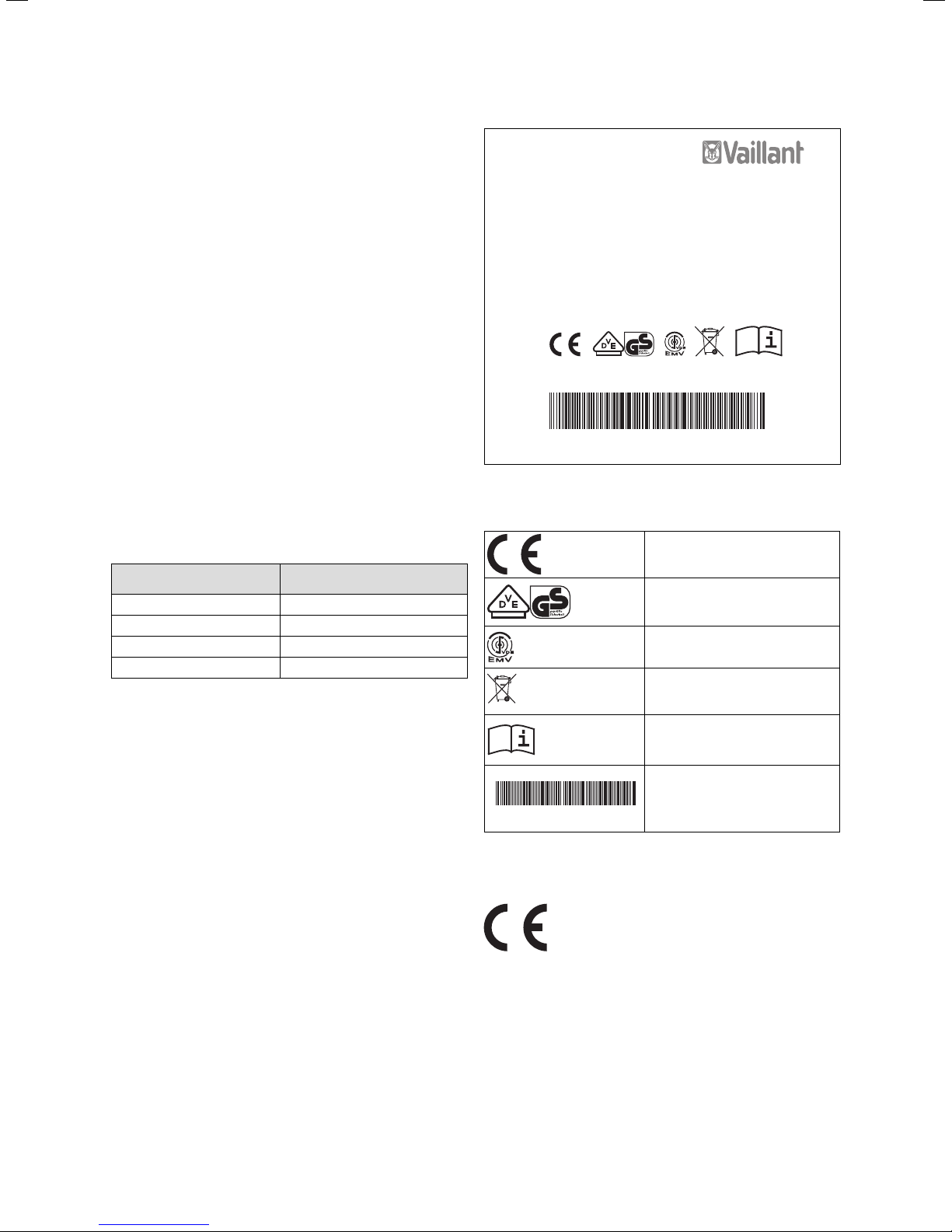
Vaillant GmbH Remscheid / Germany
VED E 18/7 P
18 kW; 400 V 3~ 50Hz
1MPa (10bar); p 15 >= 900 Ohm cm; IP 25
Observe operating- and installation manual
Appliance must be earthed
Serial - No.
21093500200752100006000000N3
Fig. 1.1 Example of an identification plate
Explanation of the symbols on the identification plate
CE mark, see section 1.5
The VDE GS mark confirms that the
unit complies with standards and
has been tested for safety
Symbol confirming conformity with
the electromagnetic compatibility
standard
Ensure proper disposal at the end
of its useful life (not household
waste)
Read the operating and
1.4 Identification plate
The unit's article number is part of the serial number. To
find out the serial and article numbers, refer to the identification plate. The identification plate can be found to
21093500200752100006000000N3
installation instructions
Serial number as a bar code and in
plain text.
The 7th to 16th digits of the serial
number form the unit's article
number
the right, next to the operator control panel, under the
cover.
1.5 CE label
CE labelling shows that, based on the type
overview, the units comply with the basic
requirements of the applicable directives.
Operating instructions for the electronicVED plus electric instantaneous water heater 0020149585_00 3
Page 6
a
2 Safety
a
2 Safety
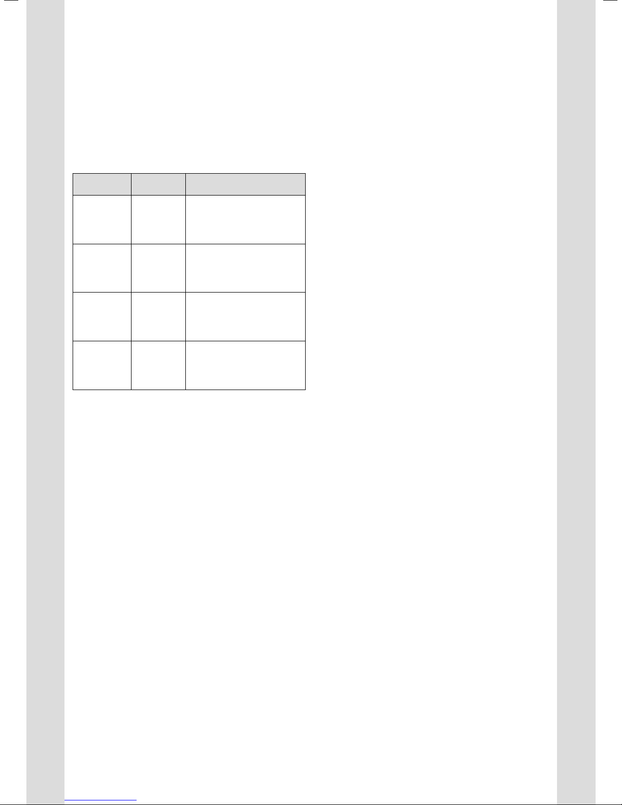
2.1 Classification of action-related warnings
The action-related warnings are classified in accordance
with the severity of the possible danger using the following warning signs and signal words:
Warning
symbol
a
e
a
b
Tab. 2.1 Meaning of warning symbols and signal words
2.2 Intended use
Vaillant electronicVED plus electric instantaneous water
heaters have been constructed using state-of-the-art
technology in accordance with the recognised safety
rules and regulations. Nevertheless, there is still a risk of
death or serious injury to the user or others or of damage to the unit and other property in the event of
improper use or use for which the unit is not intended.
This unit is not designed to be used by persons (including children) with limited physical, mental or sensory
capabilities or by persons who do not have enough experience and/or knowledge, unless they are supervised by
a person who is responsible for their safety or have
been instructed by him/her about how to use the unit.
Children must be supervised to ensure that they do not
play with the unit.
Vaillant electronicVED plus electric instantaneous water
heaters must only be used to heat up drinking water.
Vaillant electronicVED plus electric instantaneous water
heaters are suitable for use only in an enclosed, frostfree room in a domestic environment. Vaillant electronicVED plus electric instantaneous water heaters are not
suitable for use in secondary returns.
Any other use that is not specified in these instructions,
or use beyond that specified in this document shall be
considered improper use. Any direct commercial or
industrial use is also deemed to be improper. The manu-
Signal word Explanation
Danger!
Danger!
Warning.
Caution.
Imminent danger to life
or risk of severe
personal injury
Risk of death from
electric shock
Risk of minor personal
injury
Risk of material or environmental damage
facturer/supplier is not liable for any damage resulting
from such use. In this case, the user alone bears the risk.
Intended use includes the following:
– observance of the accompanying operating, instal-
lation and maintenance instructions for the Vaillant
product and any other parts and components of
the system
– compliance with all inspection and maintenance
conditions listed in the instructions.
Caution!
Improper use of any kind is prohibited.
2.3 General safety information
Installation, start-up, maintenance and repair
All work involved in the installation, initial start-up, maintenance and repair of the electronicVED plus electric
instantaneous water heater must only be carried out by
an approved heating specialist company, who also
assumes the responsibility for installing the unit properly and commissioning it for the first time. The
electronicVED plus electric instantaneous water heater
must be installed in strict compliance with these installation instructions.
Risk of death from electric shock from live lines and
connections!
During all work on the open unit, particularly on electrical lines and connections, there is a risk of death from
electric shock.
> Do not carry out any work on the unit yourself.
> Inform your heating specialist company if your
electronicVED plus is not working correctly.
Risk of death from electric shock from live lines and
connections!
The drinking water used must demonstrate resistance
greater than or equal to 900 ohm at 15 °C. Otherwise
the unit must not be used.
> Before installing the unit, ask the competent person
at your local water company to inform you about the
water resistance and conductivity.
> Consult your competent person if you have any doubt
as to the requirements for water quality.
Risk of being scalded by hot water!
The outlet temperatures at the draw-off points can be
up to 60 °C.
> When using an electronicVED plus electric instantane-
ous water heater, be aware of the risk of scalding
from high outlet temperatures.
> Set your electronicVED plus to a maximum of 43 °C if
you want to be protected from scalding.
4 Operating instructions for the electronicVED plus electric instantaneous water heater 0020149585_00
Page 7

a
Material damage inside the unit caused by poor
quality water
An electronicVED plus electric instantaneous water
heater must only be used to heat up drinking water. This
drinking water must meet the specific German or Austrian legal requirements for quality. Otherwise, it is not
possible to rule out the risk of corrosion inside the unit.
> Consult a competent person if you have any doubt as
to the requirements for water quality.
Risk of frost.
If an electronicVED plus electric instantaneous water
heater is placed out of operation for a relatively long
period of time in an unheated room in cold weather, the
water in the unit and pipes may freeze.
> Consult a competent person if you have any doubt as
to requirements.
> Ensure that your electronicVED plus electric instanta-
neous water heater is installed in a permanently frostfree room.
Material damage to the appliance caused by changes
No changes must be made to your electronicVED plus.
Safety 2
a
In the event of a fault
> If your electronicVED plus is not producing hot water
or if any other fault occurs, inform your approved
heating specialist company.
> If the electronicVED plus ever malfunctions, inform
your approved heating specialist company.
> Do not carry out any repairs yourself.
> Do not open the unit cover under any circumstances.
Operating instructions for the electronicVED plus electric instantaneous water heater 0020149585_00 5
Page 8
3 Function and operation
3 Function and operation
If you turn on the hot water at a draw-off point (mixer or
separate tap), your electronicVED plus will automatically
heat up the drinking water.
Danger!
Risk of being scalded by hot water.
a
The water temperature at the draw-off points
can reach up to 60 °C.
> When using an electronicVED plus electric
instantaneous water heater, be aware of
the risk of scalding from high outlet temperatures.
> Set your electronicVED plus to a maximum
of 43 °C if you want to be protected from
scalding.
> Section 3.1.7 "Setting the maximum temper-
ature" contains all relevant information on
the "scald protection" function, which can
be configured on your electronicVED plus.
Your electronicVED plus controls the water
temperature but not the volume you take
i
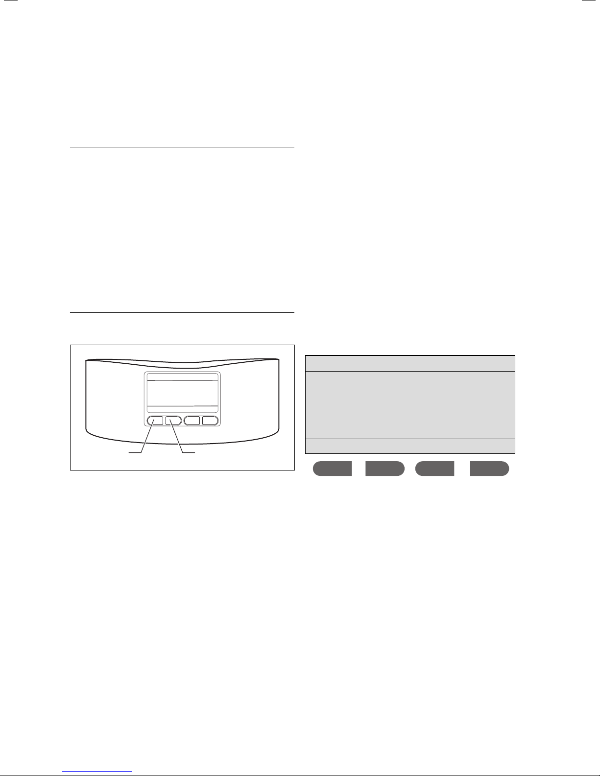
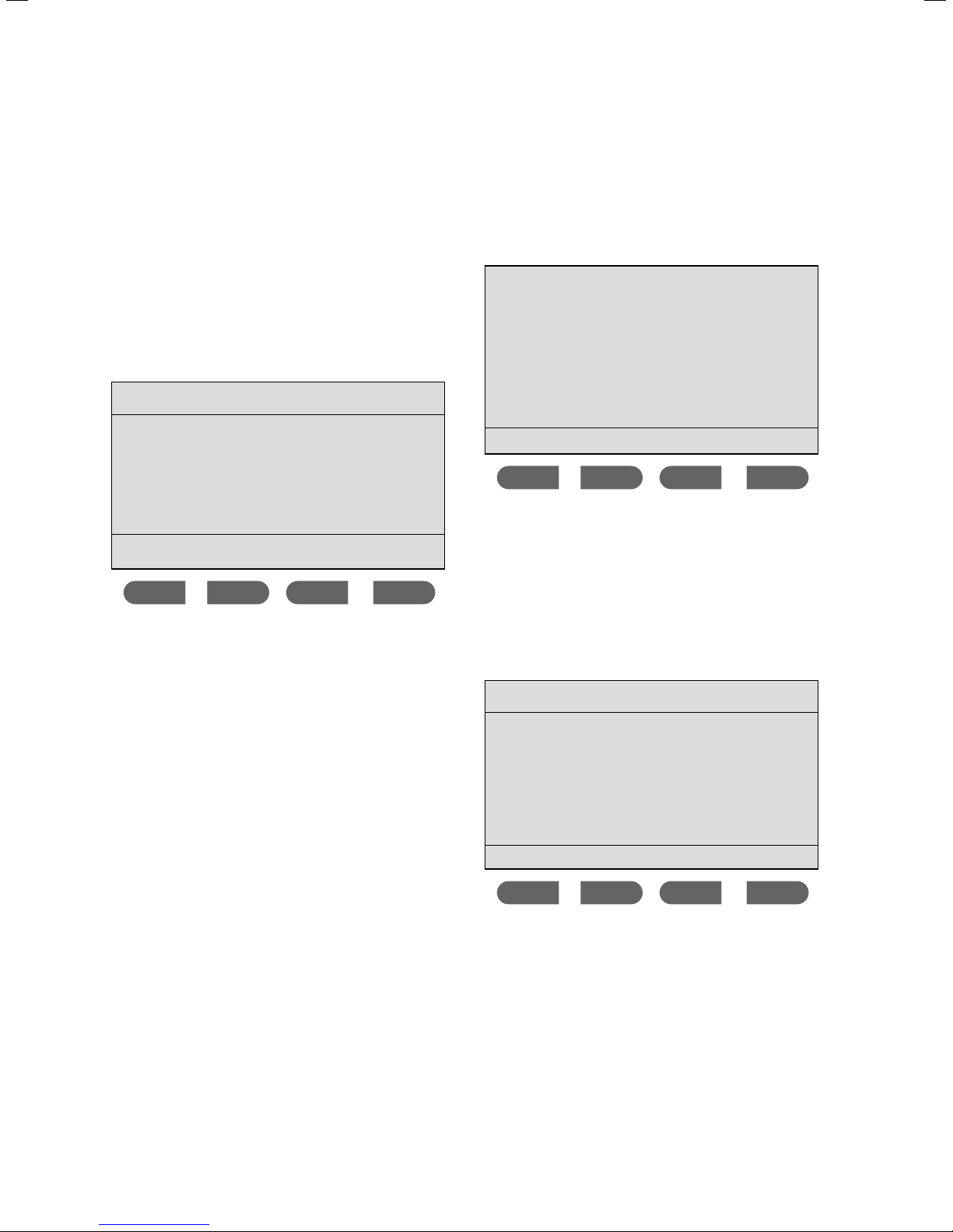
3.1 Setting the display parameters
i
The current performance features of the electronicVED
plus are displayed as soon as the unit is connected and
configured. When in operation, the display shows the
selected water temperature. Furthermore, the maximum
water temperature that can be set will be displayed on
the uppermost display line. This maximum temperature
can be set freely and can be between 30 °C and 60 °C.
The following display is an example of this.
from the draw-off point. Therefore, the
desired temperature may not be reached
when drawing large volumes, especially in
cold weather. If this occurs, briefly reduce the
water volume being drawn. The water temperature will increase very quickly.
The electronicVED plus display can be, but
does not have to be, set up before checking
the function. It is sensible to first only set the
desired hot water temperature.
max. 42 °C
°C38,5
+
+
Memo eco
1
-
-
2
Fig. 3.1 Display
> Press the + button (1) until the desired temperature is
reached. The hot water that you can now take from
the draw-off point will be at the desired temperature.
> If the temperature is too high, press the — button (2).
The water drawn will be cooler.
> Choose a temperature of between 20 °C and 60 °C to
see what suits you best.
All important display set-up options for
your electronicVED plus are described in
i
section 3.1.
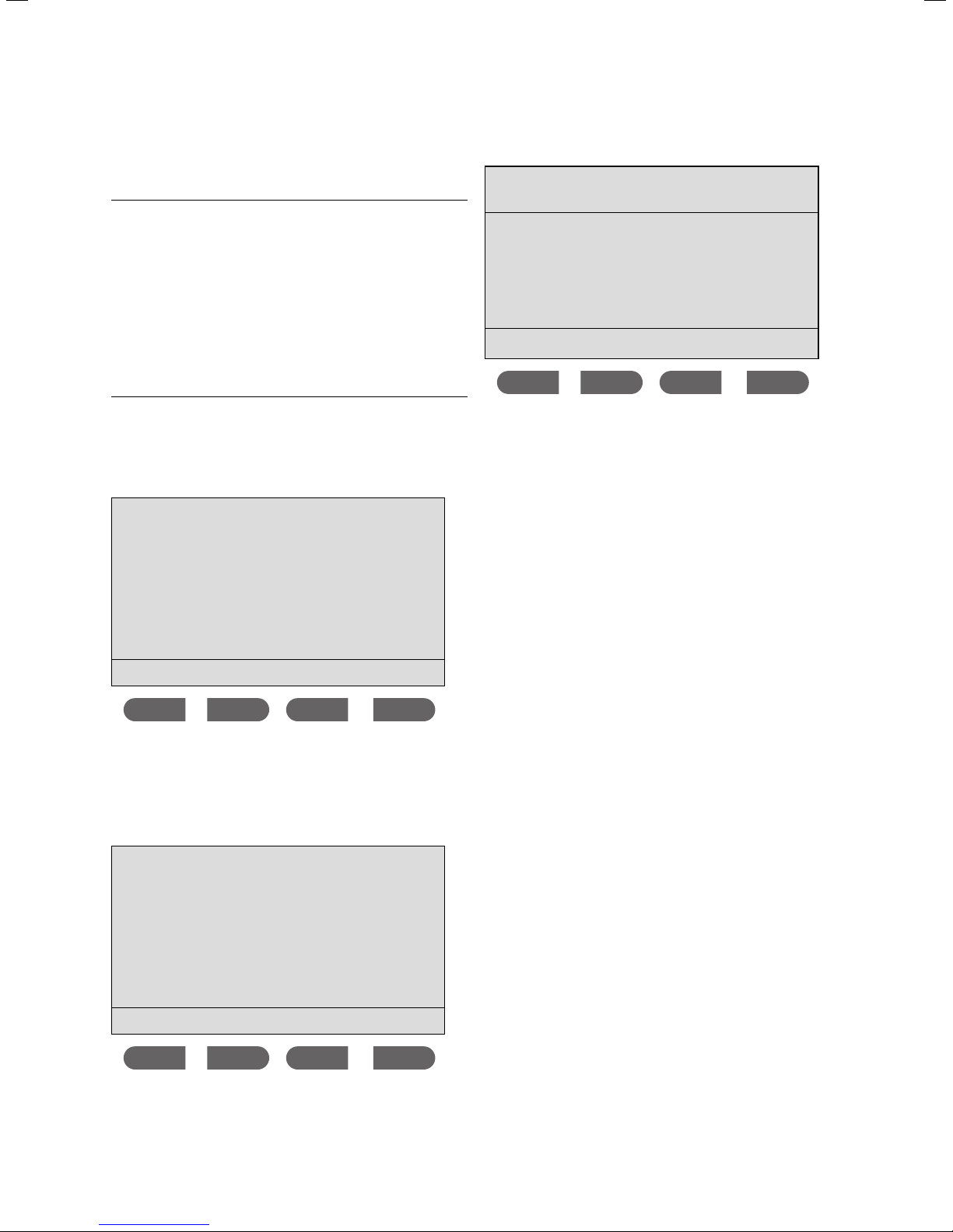
42.0 °C
- + MEMO eco
The set target temperature is factory-set to 42 °C.
The setting and display options for your VED display are
described in the following excerpts in the order that they
appear in the menus.
To access the current temperature setting quickly, you
always have two options:
> Set the current hot water temperature directly by
using the
or
> Set the current hot water temperature using the
MEMO button.
+/— buttons.
6 Operating instructions for the electronicVED plus electric instantaneous water heater 0020149585_00
Page 9

3.1.1 Key combinations on the display
Key combination Result
Briefly press MEMO and eco
simultaneously
Press MEMO for longer than
3 seconds
Main menu for setting basic functions, such as the scald protection
function, language settings and
energy consumption.
Installer level menu to call up unit
parameters.
Function and operation 3
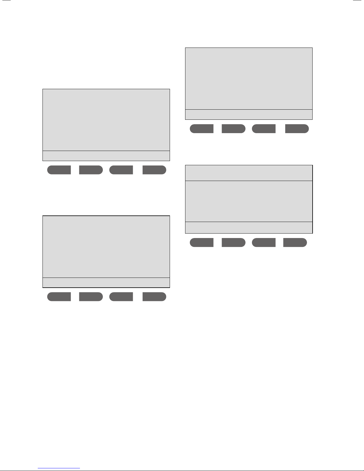
35 °C 38 °C 42 °C 50 °C
M1 M2 M3 M4
Press — and + simultaneously
for longer than 3 seconds
Tab. 3.1 Display key combinations
3.1.2 Setting the water temperature
> Press the + button to increase the water temperature.
> Press the — button to decrease the water tempera-
ture.
The water temperature can be increased or
decreased in increments of half a degree Cel-
i
3.1.3 Saved temperatures (
The
temperature to be changed quickly. By pressing the button twice you can set the desired temperature to one of
4 preset temperatures.
sius. The range of temperatures that can be
selected is between 20 °C and 60 °C.
MEMO memo function allows the current hot water
Key lock is activated. To cancel
the lock once more, press — and +
for longer than 3 seconds.
MEMO 1 to 4)
> Briefly press the button that corresponds to your
desired temperature, e.g.
You will see the following display screen:
max. 42 °C eco
M3.
42.0 °C
- + MEMO eco
The desired preset temperature is selected.
> If you want to change the desired preset temperature,
press the
You will see the following display screen:
M3 button for 3 seconds.
Memory 3
You can change the preset temperatures at
any time. However, note that you cannot set a
i
> Briefly press the
You will see the following display screen:
Operating instructions for the electronicVED plus electric instantaneous water heater 0020149585_00 7
higher temperature than the maximum temperature set in the
see section 3.1.7.
MEMO button once.
Scald protection menu;
42.0 °C
- + save
The current saved temperature and the memory location
Memory 3) are displayed.
(here:
> Use the + and — buttons to change the
perature that is displayed.
> Briefly press the
perature.
save button once to save this tem-
Memory tem-
Page 10
3 Function and operation
> Press the button to quit the Memory function. If
you previously changed the temperature without
pressing the
remembered.
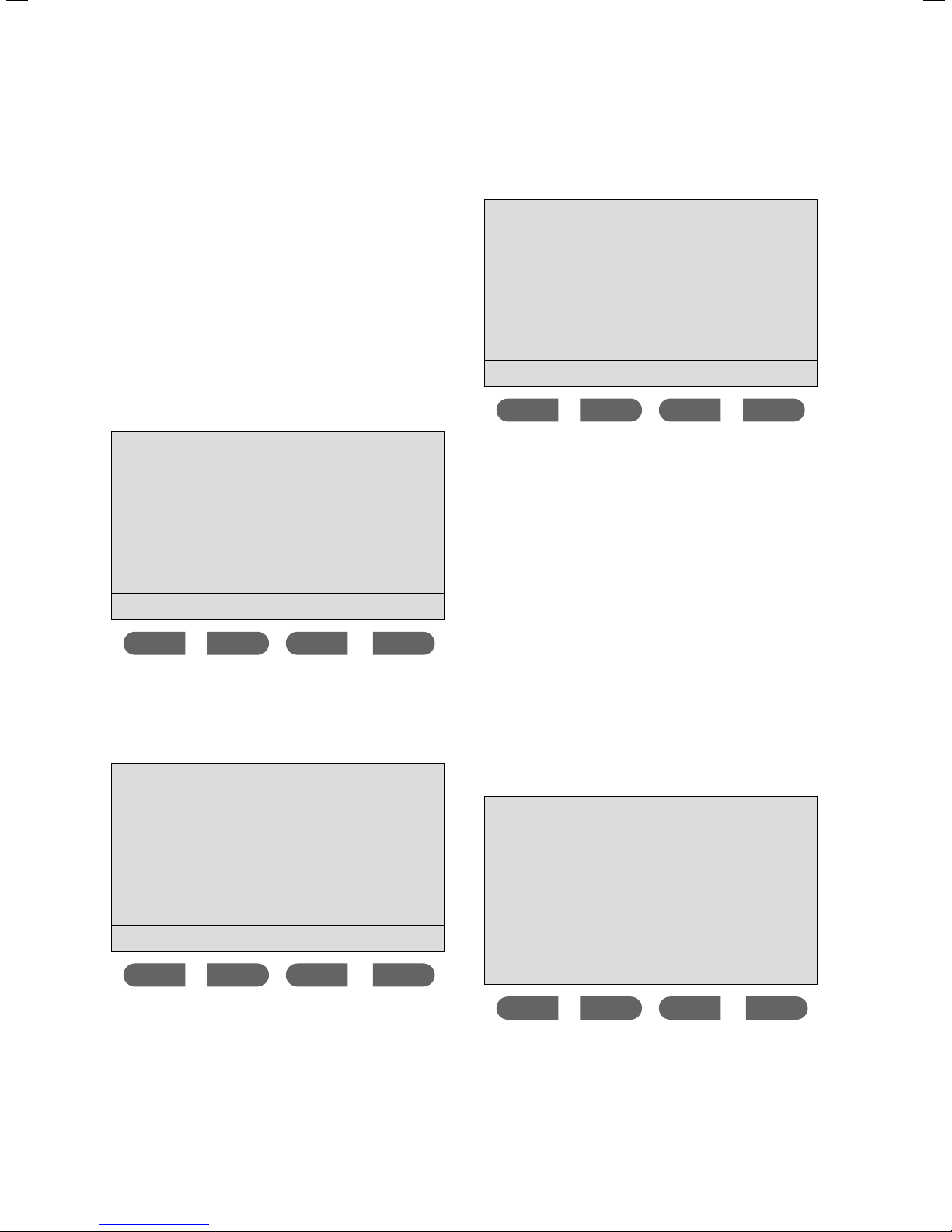
3.1.4 Setting the
eco function is a function that saves water and
The
energy. If the
reduced.
> Press the
> Press the
max. 42 °C eco
save button, this change will not be
eco function
eco function is activated, the unit output is
eco button to activate the function.
eco button again to deactivate the function.
38.0 °C
- + MEMO eco
3.1.6 Calling up the menu and going back to the
temperature display
> Briefly press the
ously to reach the
> Briefly press the
ture display.
Menu
Display settings
Scald protection
Consumption
Select language
All the basic VED settings will be carried out from this
menu.
Use the button to go back through the
menus one step at a time.
MEMO and eco buttons simultane-
Menu.
button to return to the tempera-
ok
i
If the eco function is activated, it will be shown on the
top-right of the display.
3.1.5 Activating/deactivating the key lock
> Press and hold both the + and — buttons at the same
time for longer than 3 seconds.
> Press and hold both the + and — buttons at the same
time for longer than 3 seconds again to deactivate
the key lock.
When the key lock is activated, pressing any
display button will not have any effect; all
i
functions are locked.
> Continuously press the
play screen is shown again.
button until the initial dis-
max. 42 °C
42.0 °C
- + MEMO eco
8 Operating instructions for the electronicVED plus electric instantaneous water heater 0020149585_00
Page 11
Function and operation 3
3.1.7 Setting the maximum temperature
(to prevent scalding)
Danger!
Risk of being scalded by hot water.
a
The scald protection function can only be deactivated at
the factory.
> Press the
reach the
Menu
The water temperature at the draw-off points
can reach up to 60 °C.
> When using an electronicVED plus electric
instantaneous water heater, be aware of
the risk of scalding from high outlet temperatures.
> Set your electronicVED plus to a maximum
of 43 °C if you want to be protected from
scalding.
MEMO and eco buttons simultaneously to
Menu.
Display settings
Scald protection
Consumption
Select language
> Press the
Set temperature
current: --°C
ok button.
new --°C
-+ok
> Press the + button to increase the temperature.
> Press the — button to decrease the temperature.
> Press the
ture.
> Press the
tection" menu.
The selected maximum temperature is displayed on the
top line of the water temperature display screen.
i
ok button to confirm the chosen tempera-
button twice to return to the "Scald pro-
It is not possible to request a higher water
temperature than the temperature selected
and confirmed using the
that the maximum temperature interacts with
comfort temperature function.
the
ok button. Also note
The cursor is next to the Display settings menu point.
> Press the
The cursor is next to the
> Press the
Scald protection
max. temperature
comfort temperature
The cursor is next to the max. temperature menu point.
button.
ok button.
ok
Scald protection menu point.
ok
Operating instructions for the electronicVED plus electric instantaneous water heater 0020149585_00 9
Page 12
3 Function and operation
3.1.8 Setting/activating and deactivating the
comfort temperature (scald protection)
> Press the
reach the
Menu
Display settings
Scald protection
Consumption
Select language
The cursor is next to the Display settings menu point.
> Press the
The cursor is next to the
> Press the
Scald protection
max. temperature
comfort temperature
MEMO and eco buttons simultaneously to
Menu.
button.
ok button.
ok
Scald protection menu point.
Scald protection
max. temperature
comfort temperature
The cursor is next to the comfort temperature menu
point.
> Press the
Set temperature
current: --°C
ok button.
ok
new -- °C
-+ok
The cursor is next to the max. temperature menu point.
> Press the
button once.
ok
> Press the + button to increase the temperature.
> Press the — button to decrease the temperature.
> Press the
ture.
> Press the
tion" menu.
The comfort temperature selected here can be altered
by briefly pressing the +/- key combination. If water is
drawn off within the next 30 seconds, the water will be
heated to this temperature. If no water is drawn off in
this time, or if the water stops being drawn off, the display will return to the previous temperature setting.
To deactivate the
Set comfort temperature menu on the display as
the
follows:
> Press the — button to decrease the displayed temper-
ature to below 20 °C.
-- °C will then be displayed. The comfort temperature
is then deactivated.
ok button to confirm the chosen tempera-
button to return to the "Scald protec-
comfort temperature function, go to
Also note the comfort temperature interacts
with the
max. temperature function.
i
10 Operating instructions for the electronicVED plus electric instantaneous water heater 0020149585_00
Page 13
Function and operation 3
3.1.9 Displaying and resetting the energy and water
consumption (Reset)
Note that the electronicVED plus is not a cali-
brated measuring instrument. Due to toler-
i
i
> Press the
reach the
Menu
ances in the electronic semiconductor and
sensors, the values displayed may deviate
from the real values.
The energy consumption data displayed can-
not be legally used to prepare or compare
energy consumption calculations of any kind.
MEMO and eco buttons simultaneously to
Menu.
Display settings
Scald protection
Consumption
Select language
kilowatt hours or water consumption in litres for a specific period of time (select using the
> After selection, press the
Energy consumption
since reset
the last 30 days
the last 365 days
ok button.
The cursor is next to the since reset menu point. The
display screen illustrated above is an example of the
Energy consumption sub-menu. Regardless of whether
or not you wish to query the energy or water consumption, the time cycles remain identical. You can display
the energy or water consumption data since the unit
was last reset to its factory settings (Reset), or the last
month (30 days) or the last year (365 days).
or button).
ok
The cursor is next to the Display settings menu point.
> Press the
The cursor is next to the Consumption menu point.
> Press the
Consumption
Energy consumption
Water consumption
button twice.
ok button.
The cursor is next to the Energy consumption menu
point. You can display the energy consumption in
ok
ok
> Press the
> Confirm by pressing the
To reset the display of either the energy or water consumption data to 0, proceed as follows:
> Within the
consumption
> Press the
The cursor is next to the
> Press the ok button.
Energy consumption
since reset
The display screen illustrated above is an example of
Energy consumption sub-menu. Follow the same
the
or the button to make a selection.
ok button.
Consumption menu, select either Energy
or Water consumption.
ok button.
since reset menu point.
13.4 kWh
Reset
Operating instructions for the electronicVED plus electric instantaneous water heater 0020149585_00 11
Page 14
3 Function and operation
procedure to reset the display of either the energy or
water consumption data.
> Press the
Reset button.
The display will be reset to 0.
> Press the
button to quit the display.
3.1.10 Setting the display language
> Press the
reach the
Menu
Display settings
Scald protection
Consumption
Select language
MEMO and eco buttons simultaneously to
Menu.
ok
The cursor is next to the Display settings menu point.
> Press the
button three times.
The cursor is next to the Select language menu point.
> Press the
ok button.
3.1.11 Setting the display lighting
> Press the
reach the
Menu
Display settings
Scald protection
Consumption
Select language
MEMO and eco buttons simultaneously to
Menu.
ok
The cursor is next to the Display settings menu point.
> Press the
Display settings
Lighting
Output display
Volume flow display
ok button.
German
English
Bulgarian
Croatian
Polish
Serbian
Slowenian
ok
The language marked with an arrow is the language
used on the display.
> Press the
or button to change the display lan-
guage.
> Confirm this change by pressing the
ok button.
ok
The cursor is next to the Lighting menu point.
> Press the
Lighting
is auto
on
off
auto
ok button.
ok
12 Operating instructions for the electronicVED plus electric instantaneous water heater 0020149585_00
Page 15

Function and operation 3
The following settings are possible:
on
off
automatic
The display lighting is permanently on.
The display lighting is permanently off.
When drawing hot water, the display lighting turns on. When operating the display, e.g. setting the
temperature, the display lighting
also turns on. If nothing is happening, the display lighting turns
off.
3.1.12 Activating the power display
> Press the
reach the
Menu
Display settings
Scald protection
Consumption
Select language
MEMO and eco buttons simultaneously to
Menu.
Output display
is on
on
off
ok
> Press the or button to activate (on) or to deacti-
off) the power display.
vate (
> Confirm this change by pressing the
ok button.
If the power display is activated, the current
energy consumption will be displayed in kilo-
i
watts when drawing water.
Example:
max. 60 °C eco
ok
The cursor is next to the Display settings menu point.
> Press the
Display settings
Backlight
Output display
Volume flow display
ok button.
ok
The cursor is next to the Backlight menu point.
> Press the
button.
The cursor is next to the Output display menu point.
> Press the
ok button.
41.0 °C
- + MEMO eco
12.7 kW
Operating instructions for the electronicVED plus electric instantaneous water heater 0020149585_00 13
Page 16

3 Function and operation
3.1.13 Activating the flow rate indicator
> Press the
reach the
Menu
Display settings
Scald protection
Consumption
Select language
The cursor is next to the Display settings menu point.
> Press the
Display settings
Backlight
Output display
Volume flow display
MEMO and eco buttons simultaneously to
Menu.
ok button.
ok
Volume flow display
is on
on
off
> Press the or button to activate (on) or deacti-
off) the volume flow display.
vate (
> Confirm this change by pressing the
If the volume flow display is activated, the
current water flow will be displayed in litres
i
Example:
per minute when drawing water.
max. 42 °C
ok
ok button.
41.0 °C
The cursor is next to the Backlight menu point.
> Press the
The cursor is next to the Volume flow display menu
point.
> Press the
button twice.
ok button.
ok
- + MEMO eco
8 l/min
14 Operating instructions for the electronicVED plus electric instantaneous water heater 0020149585_00
Page 17

Energy-saving tips 4, Detecting and rectifying faults 5, Care 6
Maintenance, guarantee and customer service 7 Recycling and disposal 8
4 Energy-saving tips
You can help to save energy by following the tips and
advice below:
Appropriate hot water temperature
The water should only be heated up to the extent that is
necessary for use. Any further heating will result in
unnecessary energy consumption. For you, this means
that you should:
> Activate the eco function on your electronicVED plus
(Press the
> Wherever possible, do not set the temperature higher
than you actually require. Avoid unnecessarily mixing
in cold water.
eco button).
5 Detecting and rectifying faults
Danger!
Risk of death from electric shock.
e
Live lines and connections may cause a
potentially lethal electric shock!
> Do not attempt to repair the unit yourself
under any circumstances.
> Under no circumstances should the unit
cladding be removed.
> If the unit ever malfunctions, inform your
heating specialist company immediately.
6 Care
There is no need to care for your Vaillant electronicVED
plus electric instantaneous water heater because all
internal parts are protected against dirt and moisture.
You can clean the exterior of the unit with a damp cloth
and a little soap.
7 Maintenance, guarantee and
customer service
The permanent operational readiness, safety, reliability
and long service life of your electronic VED plus electric
instantaneous water heater require annual inspections
and maintenance work to be carried out by a competent
person.
Danger!
Risk of injury and material damage due
a
b
to incorrect maintenance and repairs.
If you fail to carry out maintenance, or if
you carry this out incorrectly, this may
adversely affect the operating reliability of
the unit.
> Never attempt to perform maintenance
or repairs on your VED electric instanta-
neous water heater
> You must employ an approved heating spe-
cialist company to complete such work. We
recommend making a maintenance agreement.
Caution.
Possible material damage to the unit.
A lack of maintenance can affect the functional safety of the VED. E.g. unit defects
caused by limescale formation. In areas of
hard water (more than 14 °dH = 2.5 CaCO
mmol/l) or very hard water (more than
20 °dH = 3.6 CaCO
more frequent maintenance interval may be
required.
> Have your electronicVED plus inspected at
least every 3 years by a competent person.
> If you live in an area with very hard water,
Vaillant recommends that you have the
maintenance service carried out once a
year by a competent person.
by yourself.
mmol/l), a significantly
3
3
Do not use any abrasive scouring or cleaning
agents when cleaning the unit cladding.
i
Operating instructions for the electronicVED plus electric instantaneous water heater 0020149585_00 15
8 Recycling and disposal
If your Vaillant unit is labelled with this symbol, it
does not belong with your household waste at the
end of its useful life.
> Instead, take the unit to a collection point for recycling
electrical and electronic devices.
For more information on where to take your used electrical
or electronic devices, contact your town or district authorities, waste disposal company, or the competent person who
installed the unit.
Page 18

Page 19

For the competent person
Installation instructions
electronicVED plus
Electric instantaneous water heater
Page 20

Table of contents
Table of contents
1 Notes on the documentation ................................3
1.1 Other applicable documents .................................... 3
1.2 Storing documents .....................................................3
1.3 Symbols used ...............................................................3
1.4 Applicability of the instructions .............................. 3
1.5 CE label ......................................................................... 3
2 Safety ............................................................................4
2.1 Safety and warning information .............................4
2.1.1 Classification of action-related warnings .............4
2.2 Intended use ................................................................4
2.3 General safety information ......................................4
3 Equipment and functional description ...............6
3.1 Overview .......................................................................6
3.2 Function.........................................................................6
4 Installation .................................................................. 7
4.1 Scope of delivery ........................................................ 7
4.2 Installation site ............................................................7
4.3 Required minimum clearances ................................8
4.4 Mounting the unit to the wall ..................................8
4.4.1 Unit and connection dimensions ............................8
4.4.2 Removing the unit cladding .....................................9
4.4.3 Installing the unit ........................................................9
4.5 Connecting the hot and cold water ........................11
4.6 Connecting the unit to the electricity supply .....12
4.6.1 Electrical connection from above ..........................12
4.6.2 Electrical connection from below ..........................13
4.6.3 Optional load-shedding relay ..................................13
6 Handing over to the operator ..............................16
7 Replacement parts and accessories .................17
8 Detecting and rectifying faults ...........................17
9 Inspection and maintenance ................................18
10 Technical data ...........................................................19
5 Starting up/decommissioning ..............................13
5.1 Purging the unit .........................................................13
5.2 Fitting the unit cladding ...........................................14
5.3 Setting the display parameters ..............................14
5.3.1 Calling up the installer menu ..................................15
5.3.2 Displaying unit parameters .....................................15
5.4 Checking the system's functionality .....................16
5.5 Decommissioning .......................................................16
5.5.1 Taking out of service temporarily ..........................16
5.5.2 Taking out of service permanently ........................16
2 Installation instructions for the electronicVED plus electric instantaneous water heater 0020149585_00
Page 21

Notes on the documentation 1
1 Notes on the documentation
The following information is intended to help you
throughout the entire documentation. Other documents
apply in addition to these installation instructions.
We accept no liability for any damage caused by failure
to observe these instructions.
1.1 Other applicable documents
> When installing the electronicVED plus, you must
observe all the installation instructions for the assem-
blies and components of the system.
These installation instructions are enclosed with the
various system parts and supplementary components.
> Furthermore, observe all operating instructions
enclosed with components of the system.
1.2 Storing documents
> Pass these installation instructions and all other appli-
cable documents and, if necessary, any required tools
to the system operator.
The system operator should retain these instructions
and tools so that they are available when required.
1.3 Symbols used
The symbols used in the text are explained below:
Symbol that denotes useful tips and
i
> Symbol for a required action
1.4 Applicability of the instructions
These instructions apply for the following only:
Type designation Article number
VED E 18/7 P 0010007723
VED E 21/7 P 0010007724
VED E 24/7 P 0010007725
VED E 27/7 P 0010007726
Tab. 1.1 Identifying the unit
The unit's article number is part of the serial number. To
find out the serial and article numbers, refer to the identification plate. The identification plate can be found to
the right, next to the operator control panel, under the
cover.
information
1.5 CE label
CE labelling shows that, based on the type
overview, the units comply with the basic
requirements of the following directives:
– Electromagnetic compatibility directive (Council Direc-
tive 2004/108/EC)
– Low voltage directive (Council Directive 2006/95/EC)
3Installation instructions for the electronicVED plus electric instantaneous water heater 0020149585_00
Page 22

a
2 Safety
a
2 Safety
2.1 Safety and warning information
When installing the electronicVED plus electric instantaneous water heater, you must observe the general safety
instructions and warning notes that appear before all of
the actions.
2.1.1 Classification of action-related warnings
The action-related warnings are classified in accordance
with the severity of the possible danger using the following warning signs and signal words:
Warning
symbol
a
e
a
b
Signal word Explanation
Danger!
Danger!
Warning.
Caution.
Imminent danger to life
or risk of severe
personal injury
Risk of death from
electric shock
Risk of minor personal
injury
Risk of material or environmental damage
2.2 Intended use
Vaillant electronicVED plus electric instantaneous water
heaters have been constructed using state-of-the-art
technology in accordance with the recognised safety
rules and regulations. Nevertheless, there is still a risk of
death or serious injury to the user or others or of damage to the unit and other property in the event of
improper use or use for which the unit is not intended.
This unit is not designed to be used by persons (including children) with limited physical, mental or sensory
capabilities or by persons who do not have enough experience and/or knowledge, unless they are supervised by
a person who is responsible for their safety or have
been instructed by him/her about how to use the unit.
Children must be supervised to ensure that they do not
play with the unit.
Vaillant electronicVED plus electric instantaneous water
heaters must only be used to heat up drinking water.
Vaillant electronicVED plus electric instantaneous water
heaters are suitable for use only in an enclosed, frostfree room in a domestic environment. Vaillant
electronicVED plus electric instantaneous water heaters
are not suitable for use in secondary returns.
Any other use, or use beyond that specified, shall be
considered improper use. Any direct commercial or
industrial use is also deemed to be improper. The manufacturer/supplier is not liable for any claims or damage
resulting from improper use. The user alone bears the
risk. Intended use includes observance of the operating
and installation instructions and all
other applicable documents, as well as compliance with
the maintenance and inspection conditions.
Tab. 2.1 Meaning of warning symbols and signal words
4 Installation instructions for the electronicVED plus electric instantaneous water heater 0020149585_00
2.3 General safety information
Installation, start-up, maintenance and repair
All work involved in the installation, initial start-up, maintenance and repair of the electronicVED plus electric
instantaneous water heater must only be carried out by
an approved heating specialist company, who also
assumes the responsibility for installing the unit properly and commissioning it for the first time. The
electronicVED plus electric instantaneous water heater
must be installed in strict compliance with these installation instructions.
Risk of death from electric shock from live lines and
connections!
During all work on the open unit, particularly on electrical lines and connections, there is a risk of death from
electric shock.
> When working on the open unit, interrupt the power
supply. The unit must be de-energised.
> Check that the unit is de-energised.
> Ensure that the power cannot be restored inadvert-
ently to the unit while you are working on it.
Page 23

a
Safety 2
a
Risk of death from electric shock from live lines and
connections!
The drinking water used must demonstrate resistance
greater than or equal to 900 ohm at 15 °C. Otherwise
the unit must not be used.
> Before installing the unit, ask your water company to
inform you about the water resistance and conductivity.
Risk of being scalded by hot water!
If the VED is connected to a solar thermal system, the
intake temperature must be limited to a maximum of
60 °C by fitting structural precautions (e.g. a mixer
valve). When using the unit in conjunction with a solar
thermal system, we recommend setting the intake temperature to between 38 °C and 40 °C.
> Set the scald protection function on your
electronicVED plus to a maximum of 43 °C if you want
to be protected from scalding.
> Inform the operator that there is a risk of scalding
when the water temperature exceeds 43 °C.
Material damage inside the unit caused by poor
quality water
An electronicVED plus electric instantaneous water
heater must only be used to heat up drinking water. This
drinking water must meet the specific German or Austrian legal requirements for quality. Otherwise, it is not
possible to rule out the risk of corrosion inside the unit.
Risk of frost.
If an electronicVED plus electric instantaneous water
heater is placed out of operation for a relatively long
period of time in an unheated room in cold weather, the
water in the unit and pipes may freeze.
> Install the electronicVED plus electric instantaneous
water heater in a permanently frost-free room.
> Store the electronicVED plus electric instantaneous
water heater in a permanently frost-free area.
Material damage to the appliance caused by changes
No changes must be made to the electronicVED plus.
> Do not make any changes to the unit yourself.
> Inform the operator that they must not make any
changes to the unit or to the electricity lines or water
pipes.
In the event of a fault
> Read the "Detecting and rectifying faults" section to
find out what you must do in the case of fault.
> Inform the operator that they must not attempt to
repair the unit under any circumstances.
> Inform the operator that they must not remove the
unit cladding.
Material damage due to improper use and/or
unsuitable tools
Improper use and/or the use of unsuitable tools may
result in material damage (e.g. water leaks).
> Always use a suitable open-end spanner to tighten or
undo threaded connections.
> Do not use pipe wrenches, extensions, etc.
Installation instructions for the electronicVED plus electric instantaneous water heater 0020149585_00 5
Page 24

3 Equipment and functional description
3 Equipment and functional
description
3.1 Overview
11
10
9
Fig. 3.1 Overview of the electronicVED plus
3.2 Function
Using bare wire heating in the unit's heating block,
drinking water is heated and can then be drawn from
one or more points. The electronics measure the temperature of the cold water supply and the water volume
flow. The electrical performance required to heat the
1
water to the required temperature is calculated using
these two values. The unit's display temperature can be
changed in increments of 0.5 °C. The volume and heat of
the hot water is dependent on the electronicVED plus
performance category and settings. The output of each
2
3
VED unit is listed in section 11. In addition, the water and
energy consumption data can be linked to the performance data via the display. This means that the
electronicVED plus can be configured in such a way that
4
both the current and cumulative energy consumption
can be displayed and called up. The built-in Memo function allows 4 fixed temperatures to be saved and these
5
6
7
8
can be called up by pressing a button.
Position Component
1 Mains connection terminal
2 Upper anti-spray-water sleeve
3 Adjustment spindle
4 Safety switch
5 Electronics
Optional space underneath for mains connection termi-
6
nal
7 Cold water connection
8 Lower anti-spray-water sleeve
9 Hot water connection
10 Safety thermostat (STL)
11 Heating block
Tab. 3.1 electronicVED plus components
6 Installation instructions for the electronicVED plus electric instantaneous water heater 0020149585_00
Page 25

Installation 4
4 Installation
Risk of death!
Risk of death due to improper installation!
a
All work involved in the installation, start-up,
maintenance and repair of the electronicVED
plus electric instantaneous water heater must
only be carried out by a recognised competent person, who also assumes the responsibility for installing the unit properly and
commissioning it for the first time. The
electronicVED plus electric instantaneous
water heater must be installed in strict compliance with these installation instructions.
Flush the cold water pipes thoroughly before
installation.
i
4.1 Scope of delivery
> Check that the scope of delivery is complete (see
tab. 4.1).
Fixing points
170
Top electrical connection
Installation template
for VED
As required:
Additional fixing point for back wall
390
322
7
Mounting plate
No. Quantity Name
11
2 1 Operating and installation instructions
31
41
51
6 1 Installation plate
7 1 Installation template
Tab. 4.1 Scope of delivery
electronicVED plus electric instantaneous water
heater
Box containing fixings (2 bolts, 2 rawl plugs,
1 seal, 1 special fixing screw)
Cold water connection piece R 1/2 with a cold
water stop valve
Hot water connection piece R 1/2 supplied in the
box
The electronicVED plus electric instantaneous water
heater is completely pre-assembled. Once the unit has
been fitted to the wall, only the water and electrical
installation needs to be completed.
4.2 Installation site
Caution.
Risk of frost damage to the unit.
1
b
If an electronicVED plus electric instantaneous water heater is placed out of operation
for a relatively long period of time in an
unheated room in cold weather, the water in
the unit and pipes may freeze. This results in
damage to the unit.
> Install the unit in a permanently frost-free
room.
Bottom
electrical connection
100
Cold water connection
Hot water connection
6
Fig. 4.1 Scope of delivery
The electronicVED plus electric instantaneous
water heater meets the current safety regula-
i
2
tions for protected zone 1 and can therefore
also be installed above the bath or in a
shower area.
> Wherever possible, install the unit near the draw-off
4
5
3
point that will be most used.
7Installation instructions for the electronicVED plus electric instantaneous water heater 0020149585_00
Page 26
4 Installation
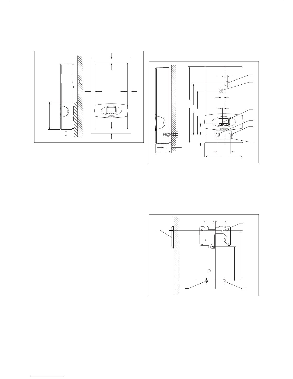
4.3 Required minimum clearances
A
E
B
D
C
Fig. 4.2 Installation clearances
Key
A At least 50 mm
B At least 50 mm
C At least 120 mm
D At least 130 mm
E Maximum 22 mm
B
C
The bottom section of the unit (D) must be level with the
unit's bearing area on the wall; to a height of at least
130 mm. Any possible wall offset (e.g. due to tiles) must
not exceed 22 mm (E). The distance to the floor must be
at least 120 mm (C). The distance above, to the left and
to the right of the unit must be at least 50 mm.
4.4 Mounting the unit to the wall
4.4.1 Unit and connection dimensions
19
16
481
322
277
R 1/2
35 35
100
Fig. 4.3 Unit dimensions
Key
1 Upper anti-spray-water sleeve
2 Central attachment
3 Display
4 Hot water connection R 1/2
5 Cold water connection R 1/2
6 Lower anti-spray-water sleeve
R Outside thread R 1/2
1
7050
5
100
240
8585
1
2
3
4
5
6
1
8 Installation instructions for the electronicVED plus electric instantaneous water heater 0020149585_00
3
Fig. 4.4 Connection dimensions
Key
1 Installation plate
2 Cold water connection
3 Hot water connection
390
322
2
Page 27
Installation 4
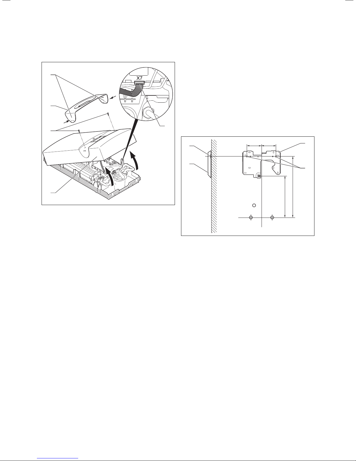
4.4.2 Removing the unit cladding
1
2
3
4
Fig. 4.5 Removing the unit cladding
> Grip the two straps (1) on the panel (2).
> Splay the two straps (pull them away from the unit).
> Remove the panel (2).
> Undo both bolts (3).
> Fold up the cover (4).
> Remove the display plug from the unit's electronics
(slot X7) (5).
> Remove the cover (4) from the unit.
4.4.3 Installing the unit
The electronicVED electric instantaneous
water heater must be hung on the wall
i
> Ensure the wall and all fixing elements are able to
bear the load. An electronicVED plus weighs approx.
4.4 kilos when filled with water.
> Using figures 4.2 to 4.4, double check that the desired
5
installation location meets the requirements.
2
1
Fig. 4.6 Fitting the installation plate
> Hold the installation template against the wall and
mark the fixing points.
> Fix the installation plate (1) to the fixing points (2)
using the rawl plugs and bolts.
vertically.
8585
1
2
390
322
i
When replacing a unit, you can use the previ-
ous drill holes as long as they are compatible
with the additional holes on the installation
plate.
9Installation instructions for the electronicVED plus electric instantaneous water heater 0020149585_00
Page 28

4 Installation
Danger!
Risk of death from electric shock due to
e
water penetration if the anti-spray-water
sleeve is completely cut away.
The anti-spray-water sleeve should prevent
water penetrating the unit along the length of
the mains connection cable. If the anti-spraywater sleeve is completely cut away, water
can very easily penetrate and damage the
unit and, in the worst case scenario, can
cause a potentially lethal electric shock.
> Never cut off the anti-spray-water sleeve
completely.
> Cut the end of the anti-spray-water sleeve
in such a way that the sleeve tightly surrounds the mains connection cable.
4
3
1
2
Fig. 4.8 Fitting and adjusting the unit
Fig. 4.7 Cutting the anti-spray-water sleeve for the cable
routing
> Depending on the location of the mains connection
cable in relation to the wall, fit the anti-spray-water
sleeve at the top or the bottom (see fig. 4.7).
Fit the anti-spray-water sleeve in such a way
that the sleeve tightly surrounds the mains
i
> Feed the cable through the anti-spray-water sleeve
into the unit's interior.
connection cable. Water must not penetrate
the unit's interior.
> Fit the unit (2) to the retaining screw (1) on the instal-
lation plate.
> Adjust the unit using the adjustment spindle (4).
> Fix the unit using the fixing screw (3).
> Align the unit (vertically and observing the clearances
detailed in fig. 4.2 to 4.4).
As an option, the electronicVED plus can be
converted into an under-counter unit. To do
i
this, the display must be rotated and screwed
to the unit cladding. Then the cladding must
be turned and attached to the unit in this
rotated position.
10 Installation instructions for the electronicVED plus electric instantaneous water heater 0020149585_00
Fig. 4.9 Optional under-counter conversion
Page 29

Installation 4
4.5 Connecting the hot and cold water
18, 21 and 24 kW electronicVED plus units are
suitable for post-heating water that has
i
> Observe the following conditions in order to correctly
fit the water connections:
already been pre-heated. It is possible to have
inlet temperatures of up to 60 °C. The unit
can thus be connected to existing solar and/
or heat pump systems. 27 kW electronicVED
plus units are not suitable as the water inlet
temperature must not exceed 25 °C.
– All cold and hot water pipes can be made of steel,
copper or plastic. It is important to check with the
manufacturer that pipes made of plastic can be
used with temperatures of 65 °C in normal operating mode. In addition, plastic pipes must be suitable
for a significantly higher load in the short term.
– An expansion relief valve on the cold water pipe is
not required.
– To simplify fitting the water connection, the bottom
section of the unit can be folded up (see (1) in
fig. 4.10). After fitting the connection, you must
fold the bottom section of the unit back down until
it is engaged again. The folding frame must not
be removed.
b
b
b
Caution.
Risk of damage to the unit resulting from
improper use and/or unsuitable tools.
Improper use and/or the use of unsuitable
tools may result in material damage (e.g.
water leaks).
> Always use a suitable open-end spanner
to tighten or undo threaded connections.
> Do not use pipe wrenches, extensions, etc.
Caution.
Possible damage caused by leaking water
connections.
Leaks may occur due to strains in the line
material.
> Take care not to strain the lines as you
tighten the water connections.
Caution.
Possible damage caused by unsuitable
plastic pipes.
Damage may be caused by unsuitable plastic
pipes.
> When using plastic pipes, ensure that they
withstand a maximum temperature of
95 °C and maximum pressure of 1 MPa
(10 bar) for at least one hour (check manufacturer's specifications).
> When using plastic pipes, ensure that they
conform with DIN 16893 and DIN 16892
(check manufacturer's specifications).
1
Fig. 4.10 Unit's folding frame
11Installation instructions for the electronicVED plus electric instantaneous water heater 0020149585_00
Page 30

4 Installation
4.6 Connecting the unit to the electricity supply
7
6
5
1
2
3
4
Fig. 4.11 Water connections
> Put hemp on the two double nipples (2 and 6) and
use the connections to screw the double nipples to
the wall (1 and 7).
> Insert the seals (3) in the cap nuts of the cold (4) and
hot water connections (5).
> Screw the cold water connection piece (4) to the cold
water connection double nipple (2) in the wall (1).
> Screw the hot water connection piece (5) to the hot
water connection double nipple (6) in the wall (7).
> Insert a seal in the cap nut of the unit-side hot water
connection.
Caution.
Risk of damage due to pipes being blocked
b
by foreign bodies in the water.
A water filter that stops foreign bodies entering the unit must be fitted to the cold water
flow. The unit must not be used without a
water filter. A water filter has been fitted
inside the pipe at the factory.
> During installation, check that the water
filter is present.
Danger!
Risk of death from electric shock from live
e
> When connecting the electricity supply, also observe
the local regulations from the electricity supply company as well as the specifications on the identification
plate.
> Also note the following conditions:
lines and connections!
> Isolate all supplies from the power supply
before carrying out electrical work.
> Check that there is no voltage in the supply
lines and connections.
> Ensure that the power cannot be restored
inadvertently to any of the supply lines and
connections while you are working on the
unit.
– The unit must be installed using a permanent con-
nection.
– The permanent connection must be equipped with
a customer-supplied partition that has a contact
separation of at least 3 mm on all lines. A line protection switch, for example, is suitable for this
purpose.
– The unit must be connected to the protective
earth.
– The unit is delivered pre-assembled. When connect-
ing the electricity supply, only the electricity line
needs to be fed in to the unit and connected. This
happens using one of the two anti-spray-water
sleeves that prevent water penetrating the unit;
see fig. 4.7, Cutting the anti-spray-water sleeve for
the cable routing. The connection is fixed to the
upper section of the unit at the factory. If required,
it can be connected to the lower section of the unit
but the electricity line must be fed through the
lower anti-spray-water sleeve.
> Check that the cold water filter fitted at the factory is
in the correct position in the unit-side cold water connection. The cold water filter is an additional seal on
the cold water side.
12 Installation instructions for the electronicVED plus electric instantaneous water heater 0020149585_00
4.6.1 Electrical connection from above
The electricity line is fed through the upper anti-spraywater sleeve (see (2) in fig. 4.12). Figure 4.7 explains how
the anti-spray-water sleeve must be prepared.
> Connect the individual conductors to L1, L2 and L3,
and the protective earth to the mains connection terminal (1 in fig. 4.12).
Page 31

Installation 4
Starting up/decommissioning 5
1
2
6
3
3a
Fig. 4.12 Electrical connection from above or below
4.6.2 Electrical connection from below
The electricity line is fed through the lower anti-spraywater sleeve (5). Figure 4.7 explains how the anti-spraywater sleeve must be prepared.
> Unscrew the mains connection terminal (1) (see
fig. 4.12).
> Move the mains connection terminal (6), including the
internal cable, to the lower position (4) in the unit.
> Screw the mains connection terminal to the lower
position (4).
> Pay particular attention to the internal protective
earth (3) that is screwed to position 3a.
> Check again that the mains connection terminal
cables are correctly positioned.
> Connect the individual conductors to L1, L2 and L3,
and the protective earth to the mains connection terminal (1 in fig. 4.12).
4
5
5 Starting up/decommissioning
5.1 Purging the unit
Caution.
Risk of damage from heating wire dry fire.
b
To start up the unit, proceed as follows:
> De-energise the unit.
> Open the cold water stop valve.
> Close and open the hot water draw-off valve several
times. The unit will then be purged. In normal operating mode, the unit will not need to be purged again.
The unit must be purged every time it is
started up. Otherwise, there is a risk of dry
fire and, as a consequence, damage to the
unit.
> Ensure that the unit is de-energised every
time the unit is started up or decommissioned.
> Check that there is no voltage in the supply
lines and connections.
> Ensure that the power cannot be restored
inadvertently to any of the supply lines and
connections while you are working on the
unit.
1
2
4.6.3 Optional load-shedding relay
If required, a load-shedding relay that conforms with
current standards can be connected to the electronicVED plus. This relay will turn other power consumers
off while hot water is being drawn off so that there is no
overloading. The load-shedding relay must fulfil the following criteria:
– Input current < 15 A
– Continuous current > 50 A
> Install the optional load-shedding relay to the outer
conductor that is connected to the L2 mains connection terminal of the electronicVED plus.
Fig. 5.1 Safety switch
> Push the safety switch (1) in, as shown in fig. 5.1.
If the display cable is not plugged into the
electronics, the power cannot be regulated.
i
The water temperature that the unit then
provides will comply with the last value set.
13Installation instructions for the electronicVED plus electric instantaneous water heater 0020149585_00
Page 32

5 Starting up/decommissioning
5.2 Fitting the unit cladding
1
2
3
Fig. 5.2 Fitting the unit cladding
> Plug the display cable into slot X7 of the unit's elec-
tronics, as illustrated in Figure 5.1, position (2).
> Put the unit cladding (3) on.
> Tighten both bolts (2).
> Grip the panel (1) using the two straps.
> Splay the two straps (slightly pull the panel apart).
> Put the panel (1) on.
> Make sure that the hot water draw-off valve is closed.
> Connect the unit to the electrical mains (switch on the
fuse).
5.3 Setting the display parameters
The electronicVED plus display can be, but
does not have to be, set up before checking
i
The current performance features of the electronicVED
plus are displayed as soon as the unit is connected and
configured. When in operation, the display shows the
desired water temperature. Furthermore, the maximum
water temperature that your VED provides will be displayed on the top display line. This maximum flow temperature can be set freely and can be between 30 °C and
60 °C. The following display is an example of this.
the function. It is sensible to first only set the
desired hot water temperature.
max. 42 °C
42.0 °C
- + MEMO eco
The set target temperature is factory-set to 42 °C.
To access the current temperature setting quickly, you
always have two options:
> Set the current hot water temperature directly by
using the
or
> Set the current hot water temperature using the
MEMO button.
+/— buttons.
14 Installation instructions for the electronicVED plus electric instantaneous water heater 0020149585_00
i
The settings for the installer menu on the
electronicVED plus display are described
below. You can find a detailed description of
all the display functions in the instructions for
use included in this document.
Page 33

Starting up/decommissioning 5
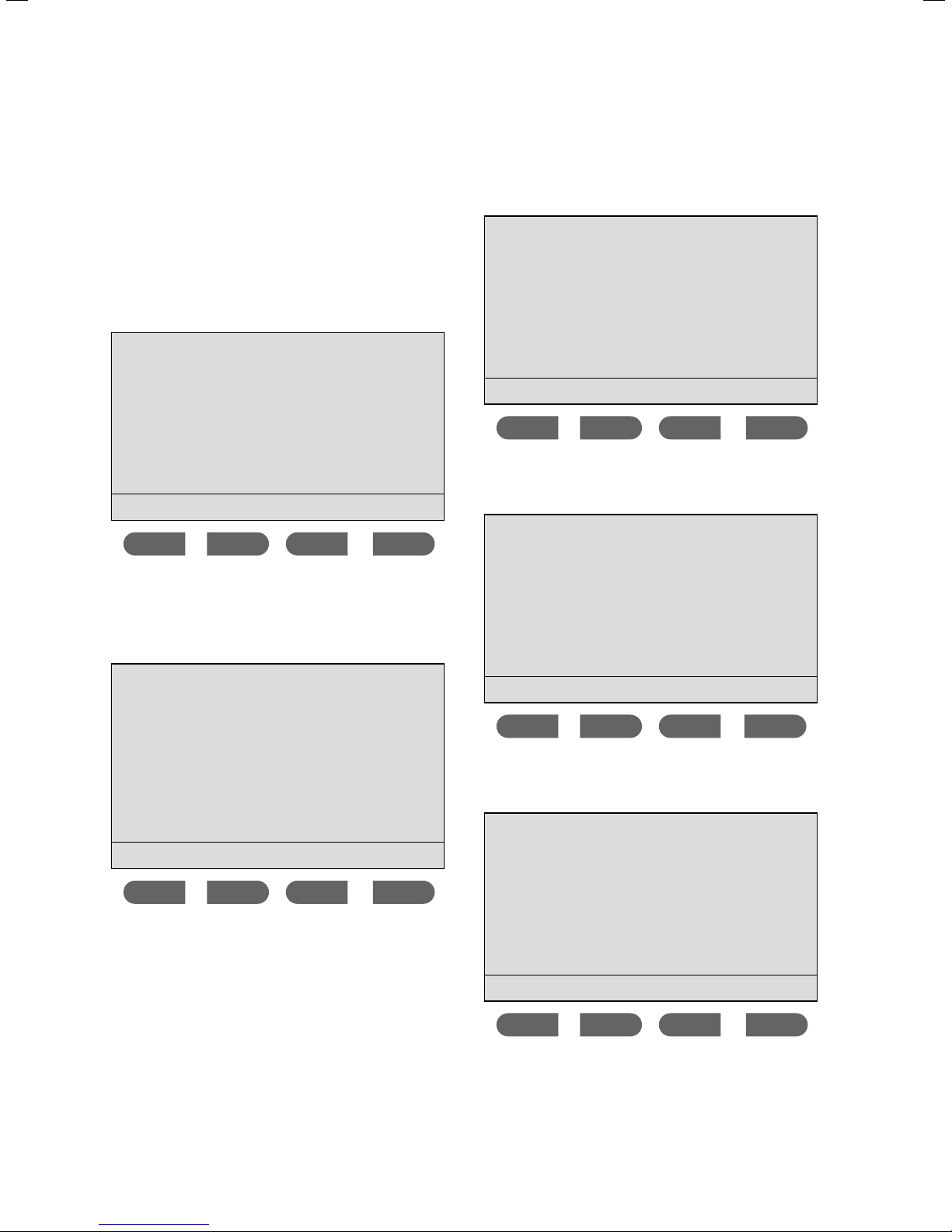
5.3.1 Calling up the installer menu
> Press and hold the
MEMO button for longer than
3 seconds to reach the installer menu.
Appliance data
Remote control
ok
Using this menu, you have access to the current and
cumulated
Appliance data.
5.3.2 Displaying unit parameters
You are in the installer menu. The cursor is next to the
Appliance data menu point.
> Press the
ok button.
Current appl. data
Inlet temp. 21 °C
Desired temp. 38 °C
Outlet temp.
Output 12.0 kW
Flow rate 8.0 l/min
ok
The following information is displayed:
The current temperature of the
Inlet temp.
Desired temperature
Outlet temp.
Output
Flow rate
Tab. 5.1 Current appliance data
drinking water, as measured at the
unit's cold water inlet.
The target temperature set on the
unit for the hot water output.
The current temperature of the
hot water, as measured at the hot
water outlet.
The unit's current output, measured in kilowatts.
The current flow rate, measured in
litres per minute.
---
Appliance data
current
cumulated
ok
The cursor is next to the current menu point.
> Press the
ok button.
> Press the button to return to the Appliance data
menu.
The cursor is next to the
> Press the
button.
The cursor is next to the
> Press the
ok button. The cumulated appliance data
current menu point.
cumulated menu point.
will be displayed.
Appl. data history
Operated time 548 h
Period of use 112 h
Energy 107 kW
Water 2538 Litres
ok
15Installation instructions for the electronicVED plus electric instantaneous water heater 0020149585_00
Page 34

5 Starting up/decommissioning
6 Handing over to the operator
The following information is displayed:
Operated time
Period of use
Energy
Water
Tab. 5.2 Cumulated appliance data
5.4 Checking the system's functionality
Danger!
Risk of being scalded by hot water!
a
> Using the display buttons, test the unit's output by
trying the running water at a draw-off point.
The outlet temperatures at the draw-off
points can be up to 60 °C. and can cause
scalding.
> Set the scald protection function on your
electronicVED plus to a maximum of 43 °C
if you want to be protected from scalding.
> Inform the operator that there is a risk of
scalding when the water temperature
exceeds 43 °C.
The time in hours that the unit was
connected to the power supply.
The time in hours that the unit
has produced hot water.
Energy consumption in kilowatt
hours since the unit was connected to the power supply.
Water consumption in litres since
the unit was connected to the
power supply.
5.5 Decommissioning
5.5.1 Taking out of service temporarily
The VED can be taken out of service temporarily, e.g. for
the purpose of maintenance work.
> De-energise the unit.
> Close the cold water stop valve.
5.5.2 Taking out of service permanently
To shut down the VED permanently, proceed as follows:
> De-energise the unit.
> Close the cold water stop valve.
> Carefully loosen the cold and hot water connections.
> Capture the residual water (up to 0.4 litres) left inside
the unit using a suitable container.
> Remove the unit from its mounting.
6 Handing over to the operator
Danger!
Risk of being scalded by hot water!
a
Above a water temperature of 43 °C, there is
a risk of scalding.
> Inform the operator that there is a risk of
scalding when the water temperature
exceeds 43 °C.
> Set the scald protection function on your
electronicVED plus to a maximum of 43 °C
if you want to be protected from scalding
The water temperature on the electronicVED plus can be
set in increments of 0.5 °C.
°C38,5
+
+
Memo eco
1
-
-
2
Fig. 5.3 Output selector switch
> Press the + button (1) or the — button (2) until the set
target temperature is reached.
16 Installation instructions for the electronicVED plus electric instantaneous water heater 0020149585_00
The user must be trained in the handling and function of
his electronicVED plus.
> Provide the operator with all relevant instructions and
unit documentation for safe-keeping.
> Go through the instructions for use with the operator.
> Answer any questions the operator may have.
> Draw special attention to the safety information
which the operator must follow.
> Inform the operator of the necessity to ensure that
the system is regularly inspected/maintained by a
competent person (inspection and maintenance
contract).
> Make the operator aware that the instructions should
be kept near the electronicVED plus.
Page 35

Replacement parts and accessories 7
Detecting and rectifying faults 8
7 Replacement parts and accessories
The original components of the unit were also certified
as part of the CE declaration of conformity. If you do not
use certified Vaillant genuine spare parts, this voids the
CE conformity of the unit. We therefore strongly recommend that you fit Vaillant genuine spare parts.
You can find information about available Vaillant genuine spare parts from the contact address provided on
the reverse of this document.
> If you require spare parts for servicing or repair work,
8 Detecting and rectifying faults
The faults listed here must only be rectified by an
approved heating specialist company. When rectifying
faults, note the following:
> Only use genuine spare parts for repairs.
> Make sure the parts are correctly fitted and that their
original position and alignment are retained.
> When removing water-carrying parts, capture the
residual water (up to 0.4 litres) left inside the unit
using a suitable container.
use only Vaillant genuine spare parts.
i
Fault/cause Procedure Testing/rectifying
No power. 1. Check the electrical con-
Resistance is outside the
range of < 200 ohm.
Water flow not adequate,
water pressure is too low.
Nothing shown on the display, no function can identified. The safety switch has
been triggered.
No hot water or fluctuation in
the outlet temperature.
Flow rate cannot be set or
the outlet temperature is not
reached. Defective motorised
valve.
Tab. 8.1 Possible faults and remedial action
nections
2. Check the electrical function of the heating element
3. Check the minimum water
flow rate
4. Check the safety switch Carry out the checks as described in points 1 - 5. Once you have found the
5. Check the electronics Slowly open a draw-off point near the unit until approx. 3 l/min. Check
6. Check the motorised valve The unit is ready for operation, the display electronics are connected, the
Ensure that the unit is supplied with the L1, L2 and L3 mains voltage.
Check the protective devices.
De-energise the unit and open the unit cladding.
Check all the connection line connectors.
Undo the connections 1 and 4 from the electronics. Measure the resistance
value between the connections 1 and 4 on the electronics.
The resistance must be < 200 ohm.
Ensure that there is an adequate water flow rate of more than 3 l/min. If
the water volume is too low, check the water pressure, the fittings and the
filter in the inlet. If the required water volume is not reached, check the
motorised valve.
fault, start the unit up again. If you have not found the fault, do not start
the unit up. Inform Vaillant customer service.
whether a relay switch (a click) can be heard.
No switch (click) can be heard:
De-energise the unit and remove the unit cladding.· Check that the impeller
moves freely by blowing hard on the inlet side; if necessary, clean or
replace the impeller.· Otherwise, replace the electronics.
Switch (click) can be heard:
Check that the water temperature reaches the target temperature.
Fluctuation in the outlet temperature:·
Replace the electronics.
Water temperature is not reached:·
Check the motorised valve as described in point 6.· If the motorised valve
functions correctly, change the electronics.
unit cladding is closed. De-energise the unit for approx. 10 seconds. Switch
the mains voltage on again. A motor noise must immediately be audible
(the motorised valve is starting up). If you do not hear a motor noise, the
valve is defective and must be replaced.
If the motorised valve is working perfectly again, set the temperature to
60 °C. Quickly open a draw-off point with the highest flow rate possible
(e.g. a bath). Then slowly reduce the flow rate and measure whether the
selected outlet temperature is reached.
When diagnosing and rectifying faults, always
follow the order stated in tab. 8.1 for each
individual point.
17Installation instructions for the electronicVED plus electric instantaneous water heater 0020149585_00
Page 36

9 Inspection and maintenance
9 Inspection and maintenance
Danger!
Risk of death from electric shock from live
e
– A functional and visual inspection of the unit must be
carried out every three years by a competent person.
– If the water is very hard, more regular de-scaling may
be necessary.
– If the water has a large volume of suspended matter,
the water filter in the cold water flow must be
replaced more often. At the same time, the water filter has a sealing function.
Carry out the following actions:
> Replace the water filter in the cold water flow.
> Check for deposits in the hot water pipe between the
heating block and the hot water connection.
> When re-assembling the unit, insert a new flat seal
into the hot water connection.
> Check whether the unit needs to be de-scaled and do
so if required.
lines and connections!
> Isolate all electrical supplies and connec-
tions from the power supply before carrying out maintenance or repair work.
> Check that there is no voltage in the supply
lines and connections.
> Ensure that the power cannot be restored
inadvertently to any of the supply lines and
connections while you are working on the
unit.
If the unit needs to be completely de-scaled,
attach a decalcification pump between the
i
> After de-scaling the unit, flush it thoroughly with
water.
> After de-scaling the unit, purge it (see section 5).
b
18 Installation instructions for the electronicVED plus electric instantaneous water heater 0020149585_00
cold and hot water connection.
Caution.
Risk of damage caused by leaks.
After changing the water filter in the cold
water flow, leaks may occur due to the new
filter being incorrectly fitted.
> When fitting a new water filter in the cold
water flow, make sure that the filter is correctly positioned in the pipe and that the
connection is sealed.
Page 37

10 Technical data
Technical data 10
Unit type
Art. no.
For supplying one or more draw-off points
Design Appliance for wall-mounted installation
Configuration Bare wire heating coil
Capacity l 0.4
Dimensions width
Height
Depth
Weight when filled with water kg 4.4
Performance characteristics Electronically regulated output
Water inlet temperature °C 1...60 1...25
Switch-on water volume l/min 3
Switch-off water volume l/min 2.5
Switch-on flow pressure MPa 0.015
Max. water flow rate l/min 6 7 8 9
Rated overpressure MPa 1
Rated output* (T of max. 38 K) kW 15.7/18.0 18.5/21.0 21.0/24.0 23.7/27.0
Minimum water resistance at 15 °C cm 900
Measuring voltage 3/PE~ 380/400 V; 50 Hz
Safety Complies with German and Austrian safety regulations; radio-shielded; does not
Level of protection IP 25 = sprayed-water protection
Tab. 10.1 Technical data
Unit
mm
mm
mm
VED E 18/7 P
0010007723
240
481
100
interact with the mains supply
VED E 21/7 P
0010007724
VED E 24/7 P
0010007725
1)
VED E 27/7 P
0010007726
1) = closed unit (pressure resistant)
* at 380/400 V
19Installation instructions for the electronicVED plus electric instantaneous water heater 0020149585_00
Page 38

Page 39

Page 40

Manufacturer
0020149585_00 EXPen 072012 – Subject to change
 Loading...