

Vaillant ecoTEC sustain 24, ecoTEC sustain 28, ecoTEC sustain 34 Installation And Maintenance Instructions Manual
Page 1
Installation and maintenance instructions
ecoTEC sustain
24, 28, 34
GB
Installation and maintenance instructions
Publisher/manufacturer
Vaillant GmbH
Berghauser Str. 40 D-42859 Remscheid
Tel. +49 21 91 18‑0 Fax +49 21 91 18‑2810
info@vaillant.de www.vaillant.de
Page 2

Contents
2 Installation and maintenance instructions ecoTEC sustain 0020253094_01
Contents
1 Safety .................................................................... 4
1.1 Action-related warnings ......................................... 4
1.2 Intended use.......................................................... 4
1.3 General safety information .................................... 4
1.4 Regulations (directives, laws, standards).............. 6
2 Notes on the documentation .............................. 7
2.1 Observing other applicable documents ................. 7
2.2 Storing documents................................................. 7
2.3 Validity of the instructions ...................................... 7
2.4 Benchmark............................................................. 7
3 Product description............................................. 7
3.1 Product design....................................................... 7
3.2 Information on the identification plate.................... 8
3.3 Serial number ........................................................ 8
3.4 CE label ................................................................. 8
3.5 Energy Saving Trust Endorsed Products .............. 8
4 Set-up.................................................................... 8
4.1 Transporting the unit.............................................. 8
4.2 Unpacking the product........................................... 9
4.3 Checking the scope of delivery.............................. 9
4.4 Dimensions............................................................ 9
4.5 Minimum clearances............................................ 10
4.6 Clearance from combustible components ........... 10
4.7 Using the installation template............................. 10
4.8 Wall-mounting the product................................... 10
4.9 Removing the front casing................................... 11
4.10 Removing the side section .................................. 11
5 Installation.......................................................... 11
5.1 Installation requirements ..................................... 12
5.2 Gas and water connections ................................. 13
5.3 Connecting the condensate drain pipework ........ 13
5.4 Installing the discharge pipe on the expansion
relief valve............................................................ 13
5.5 Flue installation.................................................... 13
5.6 Electrical installation ............................................ 14
6 Operation............................................................ 16
6.1 Operating concept ............................................... 16
6.2 Installer level overview......................................... 17
6.3 Calling up the installer level ................................. 17
6.4 Using diagnostics codes...................................... 17
6.5 Displaying the status codes................................. 17
6.6 Using check programmes.................................... 17
7 Start-up ............................................................... 18
7.1 Carrying out the initial start-up............................. 18
7.2 Gas type check .................................................... 18
7.3 Checking the factory setting ................................ 18
7.4 Checking and treating the heating water/filling
and supplementary water .................................... 18
7.5 Preventing low water pressure ............................ 19
7.6 Filling the condensate siphon .............................. 19
7.7 Filling and purging the heating installation .......... 19
7.8 Filling the hot water circuit ................................... 20
7.9 Switching the product on and off ......................... 20
7.10 Checking the gas settings ................................... 20
7.11 Checking leak-tightness ...................................... 22
8 Adapting the unit to the installation ................ 22
8.1 Activating diagnostics codes ............................... 22
8.2 Burner anti-cycling time ....................................... 22
8.3 Setting the maximum heating output ................... 23
8.4 Setting the maintenance interval ......................... 23
8.5 Setting the pump output....................................... 23
8.6 Setting the bypass ............................................... 24
8.7 Setting the hot water temperature ....................... 24
8.8 Handing the product over to the operator............ 24
9 Troubleshooting ................................................ 24
9.1 Checking service messages................................ 24
9.2 Rectifying faults ................................................... 25
9.3 Calling up the fault memory ................................. 25
9.4 Deleting the fault memory.................................... 25
9.5 Resetting parameters to factory settings ............. 25
9.6 Preparing the repair work .................................... 25
9.7 Replacing defective components......................... 25
9.8 Completing repair work........................................ 28
10 Inspection and maintenance ............................ 28
10.1 Observing inspection and maintenance
intervals ............................................................... 28
10.2 Checking and adjusting the gas ratio setting ....... 28
10.3 Checking the CO₂ content ................................... 29
10.4 Setting the CO₂ content ....................................... 29
10.5 Preparing the maintenance work ......................... 30
10.6 Draining the product ............................................ 30
10.7 Removing the compact thermal module .............. 30
10.8 Cleaning the heat exchanger............................... 31
10.9 Checking the burner ............................................ 31
10.10 Checking the ignition electrode ........................... 31
10.11 Cleaning the condensate siphon ......................... 32
10.12 Cleaning the filter in the cold water inlet .............. 32
10.13 Cleaning the heating filter.................................... 32
10.14 Installing the compact thermal module ................ 32
10.15 Checking the product for leak-tightness .............. 33
10.16 Checking the admission pressure of the
expansion vessel ................................................. 33
10.17 Completing inspection and maintenance work .... 33
11 Decommissioning.............................................. 33
11.1 Permanently decommissioning the product......... 33
12 Recycling and disposal..................................... 33
13 Customer service............................................... 33
Appendix ............................................................................ 34
A Check programmes – Overview ....................... 34
B Overview of diagnostics codes........................ 34
C Status codes – Overview .................................. 38
D Overview of fault codes .................................... 39
Page 3

Contents
0020253094_01 ecoTEC sustain Installation and maintenance instructions 3
E Wiring diagrams................................................. 41
E.1 Wiring diagram..................................................... 41
E.2 Wiring diagram..................................................... 42
F Inspection and maintenance work –
Overview............................................................. 43
G Opening in the flue pipe .................................... 44
G.1 Positioning of the opening of a fan-supported
flue gas pipe ........................................................ 44
G.2 Horizontal terminal positioning ............................ 45
H Commissioning Checklist ................................. 46
I Technical data.................................................... 50
Index ................................................................................... 53
Page 4
1 Safety
4 Installation and maintenance instructions ecoTEC sustain 0020253094_01
1 Safety
1.1 Action-related warnings
Classification of action-related warnings
The action-related warnings are classified in
accordance with the severity of the possible
danger using the following warning signs and
signal words:
Warning symbols and signal words
Danger!
Imminent danger to life or risk of
severe personal injury
Danger!
Risk of death from electric shock
Warning.
Risk of minor personal injury
Caution.
Risk of material or environmental
damage
1.2 Intended use
There is a risk of injury or death to the user or
others, or of damage to the product and other
property in the event of improper use or use
for which it is not intended.
The product is intended as a heat generator
for closed heating installations and for hot
water generation.
Depending on the gas-fired boiler type, the
products referred to in these instructions
must only be installed and operated in conjunction with the air/flue pipe accessories listed in the other applicable documents.
Intended use includes the following:
– observance of accompanying operating,
installation and servicing instructions for
the product and any other system components
– installing and fitting the product in accord-
ance with the product and system approval
– compliance with all inspection and main-
tenance conditions listed in the instructions.
Intended use also covers installation in accordance with the IP class.
Any other use that is not specified in these
instructions, or use beyond that specified in
this document shall be considered improper
use. Any direct commercial or industrial use
is also deemed to be improper.
Caution.
Improper use of any kind is prohibited.
1.3 General safety information
1.3.1 Risk caused by inadequate
qualifications
– Set-up
– Disassembly
– Installation
– Start-up
– Maintenance
– Repair
– Decommissioning
▶ Observe all instructions that are included
with the product.
▶ Proceed in accordance with the current
state of technology.
▶ Observe all applicable directives, stand-
ards, laws and other regulations.
1.3.2 Risk of injury due to the heavy
weight of the product
▶ Make sure that the product is transported
by at least two people.
1.3.3 Risk of death from escaping gas
What to do if you smell gas in the building:
▶ Avoid rooms that smell of gas.
▶ If possible, open doors and windows fully
and ensure adequate ventilation.
▶ Do not use naked flames (e.g. lighters,
matches).
▶ Do not smoke.
▶ Do not use any electrical switches, mains
plugs, doorbells, telephones or other communication systems in the building.
▶ If it is safe to do so, close the emergency
control valve or the main isolator.
▶ If possible, close the gas isolator cock on
the product.
▶ Warn other occupants in the building by
yelling or banging on doors or walls.
▶ Leave the building immediately and ensure
that others do not enter the building.
Page 5

Safety 1
0020253094_01 ecoTEC sustain Installation and maintenance instructions 5
▶ Notify the gas supply company or the Na-
tional Grid +44 (0) 800 111999 by telephone once you are outside of the building.
1.3.4 Risk of death from escaping flue
gas
If you operate the product with an empty condensate siphon, flue gas may escape into the
room air.
▶ In order to operate the product, ensure that
the condensate siphon is always full.
1.3.5 Risk of death from leaks if the
product is installed below ground
level
Liquid gas accumulates at floor level. If the
product is installed below ground level, liquid
gas may accumulate at floor level if there
are any leaks. In this case, there is a risk of
explosion.
▶ Make sure that liquid gas cannot escape
from the product or the gas line under any
circumstance.
1.3.6 Risk of death due to blocked or
leaking flue gas routes
Installation errors, damage, tampering, unauthorised installation sites or similar can cause
flue gas to escape and result in a risk of poisoning.
What to do if you smell flue gas in the property:
▶ Open all accessible doors and windows
fully to provide ventilation.
▶ Switch off the product.
▶ Check the flue gas routes in the product
and the flue gas diversions.
1.3.7 Risk of poisoning and burns caused
by escaping hot flue gases
▶ Only operate the product if the air/flue pipe
has been completely installed.
▶ With the exception of short periods for
testing purposes, only operate the product
when the front casing is installed and
closed.
1.3.8 Risk of death due to explosive and
flammable materials
▶ Do not use or store explosive or flammable
materials (e.g. petrol, paper, paint) in the
installation room of the product.
1.3.9 Risk of death due to cabinet-type
casing
Cabinet-type casing can give rise to dangerous situations when used on a product which
is operated with an open flue.
▶ Ensure that the product is supplied with
sufficient combustion air.
1.3.10 Risk of poisoning caused by
insufficient supply of combustion
air
Conditions: Open-flued operation
▶ Ensure that the air supply to the product's
installation room is permanently unobstructed and sufficient in accordance with the
relevant ventilation requirements.
1.3.11 Risk of death due to lack of safety
devices
The schematic drawings included in this document do not show all safety devices required for correct installation.
▶ Install the necessary safety devices in the
system.
▶ Observe the applicable national and inter-
national laws, standards and guidelines.
1.3.12 Risk of death from electric shock
There is a risk of death from electric shock if
you touch live components.
Before commencing work on the product:
▶ Unplug the mains plug.
▶ Or disconnect the product from the power
supply by switching off all power supplies
(electrical partition with a contact opening
of at least 3 mm, e.g. fuse or line protection switch).
▶ Secure against being switched back on
again.
▶ Wait for at least 3 minutes until the con-
densers have discharged.
Page 6

1 Safety
6 Installation and maintenance instructions ecoTEC sustain 0020253094_01
1.3.13 Risk of being burned or scalded by
hot components
▶ Only carry out work on these components
once they have cooled down.
1.3.14 Risk of material damage caused by
using an unsuitable tool
▶ Use the correct tool to tighten or loosen
screw connections.
1.3.15 Risk of material damage caused by
frost
▶ Do not install the product in rooms prone
to frost.
1.3.16 Risk of corrosion damage due to
unsuitable combustion and room
air
Sprays, solvents, chlorinated cleaning
agents, paint, adhesives, ammonia compounds, dust or similar substances may lead
to corrosion on the product and in the flue
gas guiding.
▶ Ensure that the supply of combustion air is
always free of fluorine, chlorine, sulphur,
dust, etc.
▶ Ensure that no chemical substances are
stored at the installation site.
▶ If you are installing the product in
hairdressing salons, painter's or joiner's
workshops, cleaning businesses or similar
locations, choose a separate installation
room in which the room air is technically
free of chemical substances.
1.4 Regulations (directives, laws,
standards)
▶ Observe the national regulations, stand-
ards, guidelines and laws.
Page 7
Notes on the documentation 2
0020253094_01 ecoTEC sustain Installation and maintenance instructions 7
2 Notes on the documentation
2.1 Observing other applicable documents
▶ You must observe all the operating and installation in-
structions included with the system components.
2.2 Storing documents
▶ Pass these instructions and all other applicable docu-
ments on to the system operator.
2.3 Validity of the instructions
These instructions apply only to:
Product article number
ecoTEC sustain 24 VUW 246/7-2 (H-
GB)
0010019980
ecoTEC sustain 28 VUW 286/7-2 (H-
GB)
0010019981
ecoTEC sustain 34 VUW 346/7-2 (H-
GB)
0010019982
Gas Council Numbers
ecoTEC sustain 24 VUW 246/7-2 (H-
GB)
47-044-79
ecoTEC sustain 28 VUW 286/7-2 (H-
GB)
47-044-80
ecoTEC sustain 34 VUW 346/7-2 (H-
GB)
47-044-81
2.4 Benchmark
Vaillant is a licensed member of the Benchmark Scheme.
Benchmark places responsibilities on both manufacturers
and installers. The purpose is to ensure that customers are
provided with the correct equipment for their needs, that it is
installed, commissioned and serviced in accordance with the
manufacturer’s instructions by a competent person approved
at the time by the Health and Safety Executive and that it
meets the requirements of the appropriate Building Regulations. The Benchmark Checklist can be used to demonstrate compliance with Building Regulations and should be
provided to the customer for future reference.
Installers are required to carry out installation, commissioning and servicing work in accordance with the Benchmark
Code of Practice which is available from the Heating and
Hotwater Industry Council who manage and promote the
Scheme.
Benchmark is managed and promoted by the Heating and
Hotwater Industry Council.
For more information visit www.centralheating.co.uk
3 Product description
3.1 Product design
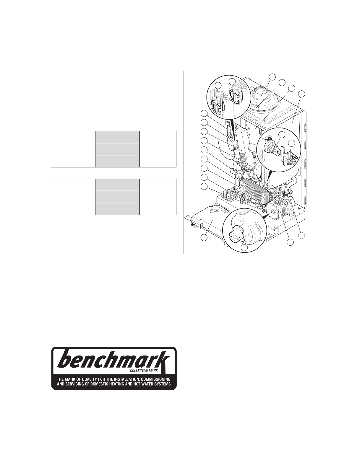
3.1.1 Functional elements
20
19
14
13
15
16
18
17
11
12
21
1
3
2
6
4
5
7
9
10
8
1 Electronics box
2 Diverter valve
3 Expansion relief valve
4 Plate heat exchanger
5 Condensate siphon
6 Gas valve
7 Fan
8 Compact thermal
module
9 Ionisation and ignition
electrode
10 Primary heat exchanger
11 Temperature sensor in
the heating flow
12 Temperature sensor in
the heating return
13 Connection for the flue
pipe
14 Flue gas measuring
stub pipe
15 Air intake pipe
16 Expansion vessel
17 Pressure sensor
18 Impeller sensor (hot
water)
19 Automatic air vent
20 Heating pump
21 Bypass
Page 8
4 Set-up
8 Installation and maintenance instructions ecoTEC sustain 0020253094_01
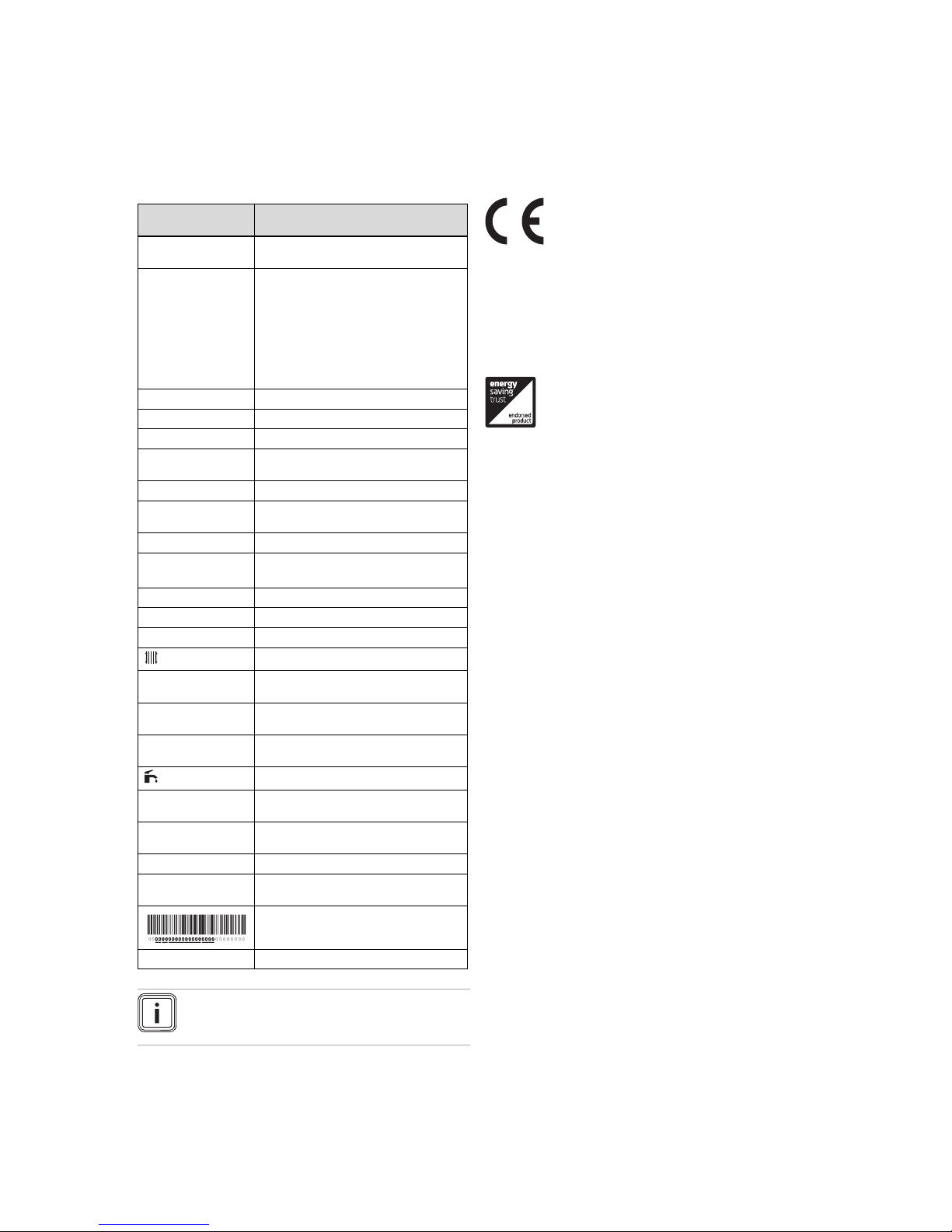
3.2 Information on the identification plate
The identification plate is mounted on the underside of the
product in the factory.
The identification plate keeps record of the country in which
the product is to be installed.
Information on the
identification plate
Meaning
Condensing technology
Efficiency class of the boiler in accordance with EC Directive 92/42/EEC
Serial number For quality control purposes; 3rd and 4th
digits = year of production
For quality control purposes; 5th and 6th
digits = week of production
For identification purposes; 7th to 16th
digits = product article number
For quality control purposes; 17th to 20th
digits = place of manufacture
... ecoTEC ... Product designation
Cat. Approved gas category
Type: Xx3(x) Permissible flue gas connections
2H / 2E / 3P / 2K... Gas group and gas connection pressure
as set at the factory
Tmax Max. flow temperature
PMS Maximum water pressure in heating
mode
NOx NOx class for the product
V
Hz
Electric connection
W Max. electrical power consumption
IP Protection class
Code (DSN) Specific product code
Heating mode
Qn Nominal heating load range in heating
mode
Pn Nominal heat output range in heating
mode
Pnc Nominal heat output range in heating
mode (condensing technology)
Hot water generation
Qnw Nominal heating load range in hot water
handling mode
Pnw Nominal heat output range in hot water
handling mode
D Specific flow rate
PMW Maximum water pressure in hot water
handling mode
Barcode with serial number
GC No. Gas council number
Note
Make absolutely sure that the product is compatible with the gas group at the installation site.
3.3 Serial number
The serial number can be found on a plastic label at the bottom of the front casing and on the identification plate.
3.4 CE label
The CE label shows that the products comply with the basic
requirements of the applicable directives as stated on the
identification plate.
The declaration of conformity can be viewed at the manufacturer's site.
3.5 Energy Saving Trust Endorsed Products
Only the most energy efficient products can carry the
‘Energy Saving Trust Endorsed Product’ brandmark making
it easy for consumers to choose products that have met strict
energy performance criteria.
Available for: Boilers, Heating controls and chemical inhibitors, the Energy Saving Trust endorsed product brandmark
gives consumers confidence that a product will cost less to
run, help lower energy bills and reduce carbon emissions.
About the Energy Saving Trust
Energy Saving Trust is an independent and impartial organisation that provides trusted energy saving advice to empower millions of people to lead affordable, low energy lifestyles. For more information visit energysavingtrust.org.uk
4 Set-up
4.1 Transporting the unit
Important: With regard to the regulations of 1992 concerning
the manual handling of loads, the unit exceeds the weight
that can be lifted by a single person.
4.1.1 General
▶ Hold the load as close as possible to your body. Do not
twist your body – instead, reposition your feet.
▶ If the unit is being lifted by two persons, ensure your
movements are coordinated during lifting.
▶ Avoid bending your upper body – do not lean forwards or
to the side.
▶ Wear appropriate cut-resistant and non-slip gloves to
protect yourself against sharp edges and maintain a safe
and secure grip.
▶ If required, get somebody to assist you in this.
4.1.2 Unloading the box from the delivery van
▶ It is recommended that two people lift the unit together.
▶ Lift the box using the straps provided.
▶ Use safe lifting techniques – keep your back straight and
bend your legs at the knee.
▶ Hold the load as close as possible to your body.
Page 9
Set-up 4
0020253094_01 ecoTEC sustain Installation and maintenance instructions 9
▶ If the unit is being lifted by two persons, ensure your
movements are coordinated during lifting.
▶ If required, get somebody to assist you in this.
4.2 Unpacking the product
1. Remove the product from its box.
2. Remove the protective film from all parts of the product.
4.3 Checking the scope of delivery
▶ Check that the scope of delivery is complete and intact.
4.3.1 Scope of delivery
Quantity
Description
1
Heat generator
1
Bag with accessories:
– Hanging bracket
– Bag with seals
– Bag with bolts and rawl plugs
– Installation template
– Flexible condensate drain pipework
– Bag containing the hydraulic connections
1
Enclosed documentation
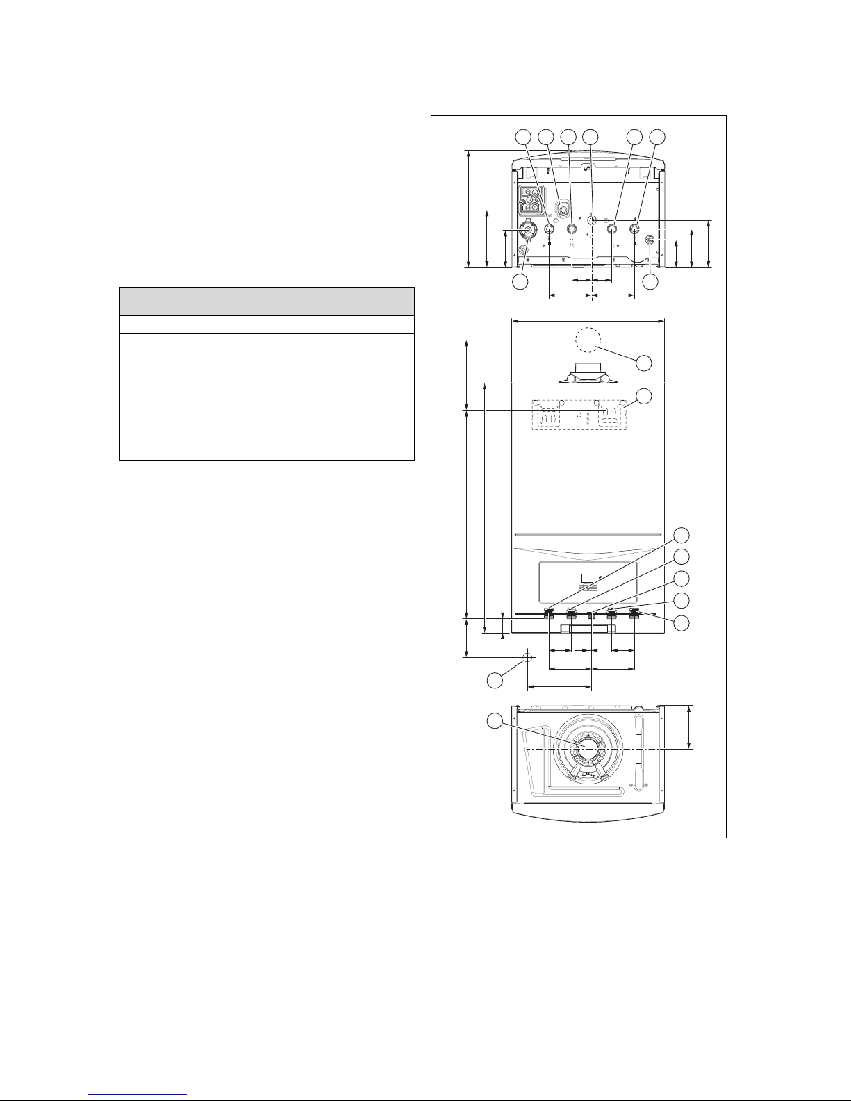
4.4 Dimensions
99
164
75
110
135
338
58 58
123123
440
125
180
40
123 123
183
65 65
600
720
A
10
1 8
9
10
11
12
2
4
5
6
7
2 43 5 6 7
1 Condensate siphon
(condensate discharge
connection, 21.5 mm
diameter)
2 Heating flow connec-
tion, G3/4
3 Heating expansion relief
valve drain pipework
connection, 15 mm
diameter
4 Hot water connection,
G3/4
5 Gas connection, G1/2
6 Cold water connection,
G3/4
7 Heating return connec-
tion, G3/4
8 Drain cock
Page 10
4 Set-up
10 Installation and maintenance instructions ecoTEC sustain 0020253094_01
9 Flue pipe wall duct
A = see installation
template (60/100 mm
diameter air/flue pipe)
A = 235 mm
(80/125 mm diameter
air/flue pipe)
10 Product holder
11 R1 tundish/condensate
siphon connection
12 Flue pipe connection
Consult the installation template that is supplied to find the
dimension A.
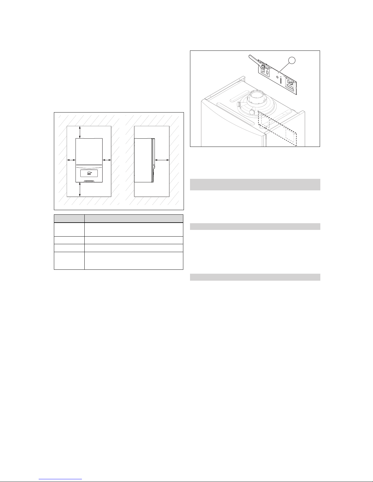
4.5 Minimum clearances
C C
AB
D
Minimum clearance
A 165 mm: Flue pipe, 60/100 mm diameter
275 mm: Flue pipe, 80/125 mm diameter
B 180 mm; optimum approx. 250 mm
C 5 mm; optimum approx. 50 mm
D 500 mm clearance in front of the heat generator
to enable easy access for maintenance work (the
same as a door opening).
4.6 Clearance from combustible components
It is not necessary to maintain a clearance between the
product and components made of combustible materials that
go beyond the minimum clearances (see page).
4.7 Using the installation template
▶ Use the installation template to ascertain the locations at
which you need to drill holes and make breakthroughs.
4.8 Wall-mounting the product
1
1. Check whether the wall has sufficient load-bearing capacity to bear the operational weight of the product.
2. Check if the supplied fixing material may be used for
the wall.
Conditions: The load-bearing capacity of the wall is sufficient, The fixing
material may be used for the wall
▶ Wall-mount the product as described.
▶ Install the hanging bracket (1) on the wall.
▶ Hang the product on the product bracket from above
using the suspension bracket.
Conditions: The load-bearing capacity of the wall is not sufficient
▶ Ensure that wall-mounting apparatus on-site has a suf-
ficient load-bearing capacity. Use individual stands or
primary walling, for example.
▶ Do not wall-mount the product if you cannot provide
wall-mounting apparatus with a sufficient load-bearing
capacity.
Conditions: The fixing material may not be used for the wall
▶ Wall-mount the product as described using the adapted
fixing material provided on-site.
Page 11
Installation 5
0020253094_01 ecoTEC sustain Installation and maintenance instructions 11
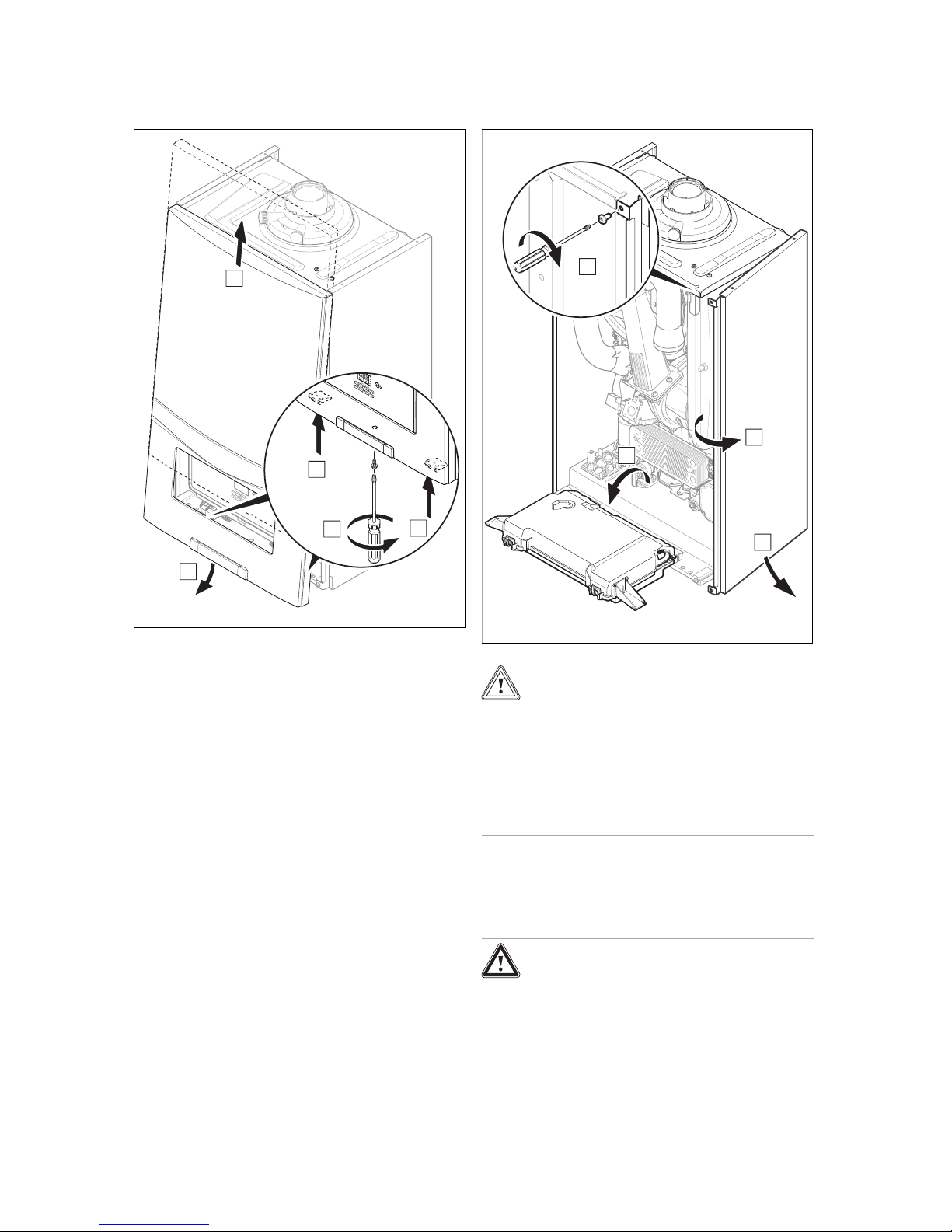
4.9 Removing the front casing
A
B
B
C
D
▶ Remove the front casing as shown in the illustration.
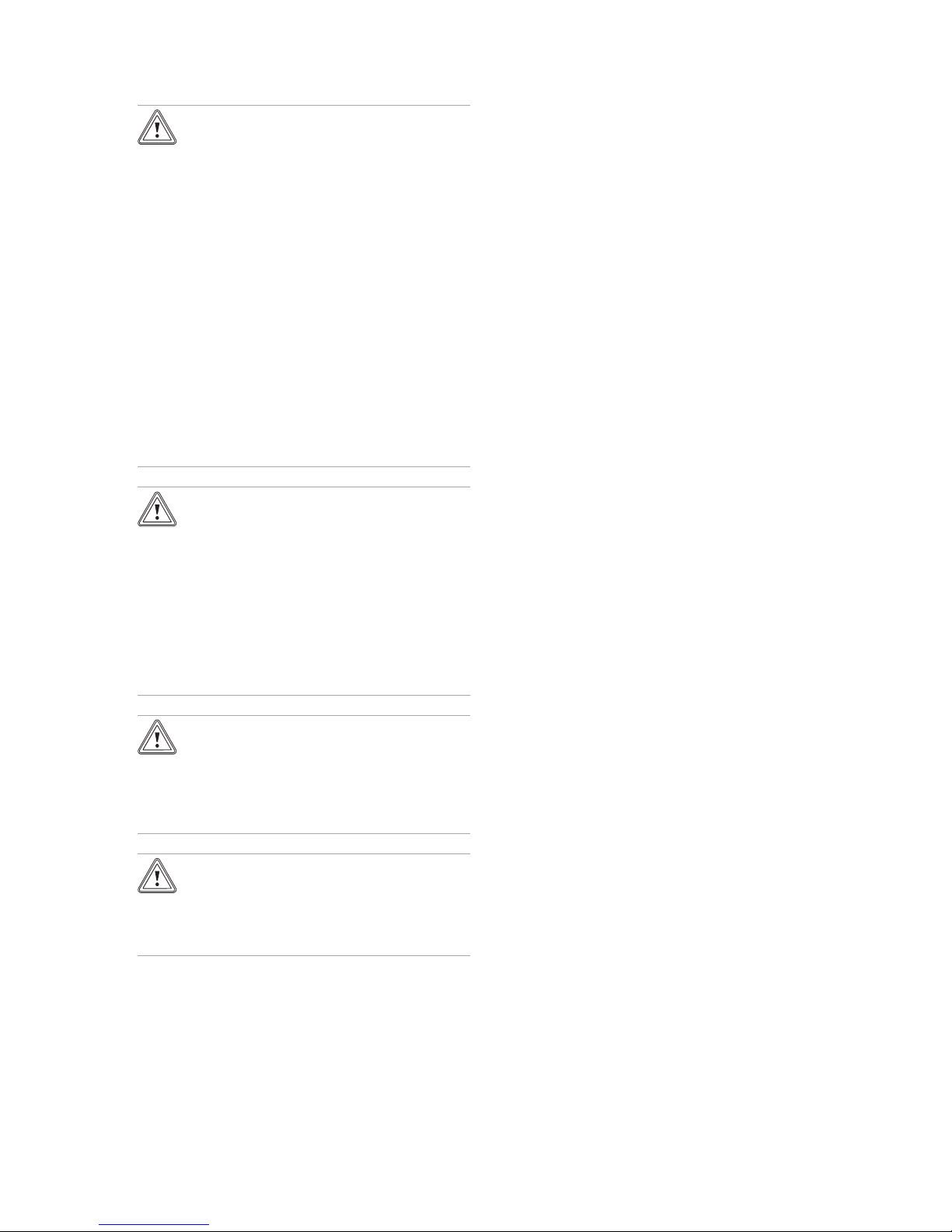
4.10 Removing the side section
2X
A
B
C
D
Caution.
Risk of material damage caused by mech-
anical deformation.
Removing both side sections may cause
mechanical distortion in the product, which
may cause damage to the piping, for example, and potentially result in leaks.
▶ Always only remove one side section –
never both side sections at the same time.
▶ Remove the side section as shown in the illustration.
5 Installation
Danger!
Risk of explosion or scalding caused by
incorrect installation.
Stresses in the connection cable can cause
leaks.
▶ Make sure there is no stress in the con-
nection cables when they are installed.
Page 12
5 Installation
12 Installation and maintenance instructions ecoTEC sustain 0020253094_01
Caution.
Risk of material damage due to the gas
leak-tightness test.
At a test pressure of >11 kPa (110 mbar), gas
leak-tightness tests may cause damage to
the gas valve.
▶ If, during gas leak-tightness tests, you
also place the gas lines and the gas valve
in the product under pressure, use a max.
test pressure of 11 kPa (110 mbar).
▶ If you cannot limit the test pressure to
11 kPa (110 mbar), close any gas isolator
cocks that are installed upstream from the
product before you carry out the gas leaktightness test.
▶ If, during gas leak-tightness tests, you
have closed the gas isolator cock that is
installed upstream of the product, relieve
the gas line pressure before you open this
gas isolator cock.
Caution.
Risk of material damage caused by corro-
sion
Due to non-diffusion-tight plastic pipes in the
heating installation, air gets into the heating
water. Air in the heating water causes corrosion in the heat generator circuit and in the
product.
▶ If you use non-diffusion-tight plastic pipes
in the heating installation, ensure that no
air gets into the heat generator circuit.
Caution.
Risk of material damage due to heat trans-
fer during soldering.
▶ Only solder connection pieces if the con-
nection pieces are not yet screwed to the
service valves.
Caution.
Risk of material damage caused by
changes to the connected pipes.
▶ Only bend connection pipes if they have
not yet been connected to the product.
5.1 Installation requirements
5.1.1 Information on liquid gas operation
In the as-delivered condition, the product is preset for operation with the gas group indicated on the identification plate.
If you have a product that has been preset for operation with
natural gas, you must convert it to run on liquid gas. You will
need a conversion kit for this. The conversion procedure is
described in the manual supplied with the conversion kit.
5.1.2 Purging the liquid gas tank
If the liquid gas tank is not purged properly, this may result in
ignition problems.
▶ Ensure that the liquid gas tank has been purged properly
before installing the product.
▶ If required, contact the filler or the liquid gas supplier.
5.1.3 Using the correct type of gas
Using the incorrect type of gas may cause fault shutdowns in
the product. Ignition and combustion noise may occur in the
product.
▶ Only use the gas type listed on the identification plate.
5.1.4 Required preliminary work
1. Make sure that the existing gas meter is capable of
passing the rate of gas supply required.
2. Install a system separator (to be provided on-site) directly on the cold water connection for the combination
unit.
3. Check that the volumetric capacity of the expansion
vessel is sufficient for the system volume.
▽ If the volume of the expansion vessel is insufficient
for the system.
▶ Install an additional expansion vessel in the
heating return, as close to the product as possible.
▶ Install a non-return flap at the product's outlet
(heating flow).
4. Ensure that the system has the following components:
– A cold water stop cock for the unit
– A gas stopcock for the unit
– A filling and draining device in the heating installa-
tion
Page 13
Installation 5
0020253094_01 ecoTEC sustain Installation and maintenance instructions 13
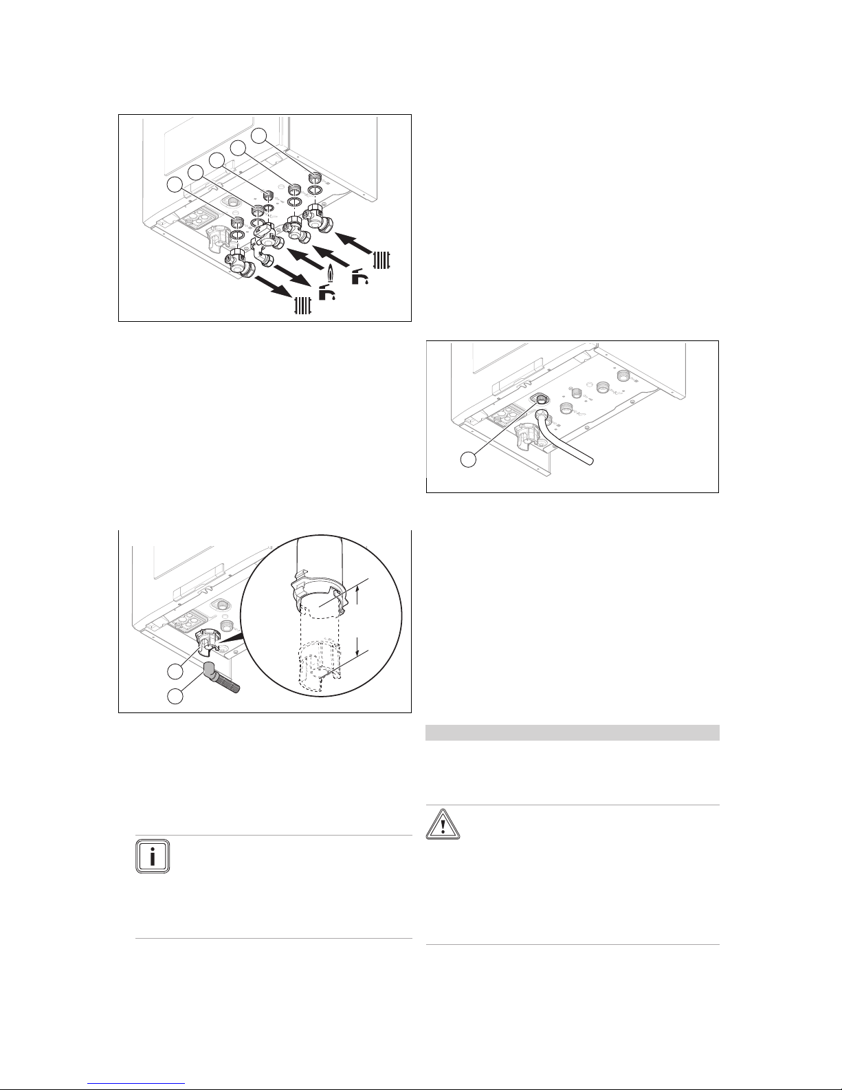
5.2 Gas and water connections
1
2
3
4
5
1 Heating flow connec-
tion, G3/4
2 Hot water connection,
G3/4
3 Gas connection, G1/2
4 Connection for the cold
water supply line, G3/4
5 Heating return connec-
tion, G3/4
1. Connect the water and gas connections in accordance
with the applicable standards.
2. Purge the gas line before start-up.
3. Check whether the connections (→ Page 22) are leaktight.
4. Check the entire gas line properly for leak-tightness.
5.3 Connecting the condensate drain pipework
min.
180
1
2
▶ Follow the instructions listed here and observe directives
and local regulations on condensed water discharge.
▶ Use PVC or another material that is suitable for draining
the non-neutralised condensed water.
▶ If you cannot guarantee that the materials from which the
condensate discharge pipe is made are suitable, install a
system to neutralise the condensate.
Note
The condensate drain pipework must have a
continuous fall (45 mm per metre) and should
whenever possible terminate at a suitable
drain point within the heated envelope of the
building that will remain frost free under long
periods of low external temperatures.
▶ Connect the condensate siphon (1). Use the supplied
condensate drain hose (2) to do this.
▶ Connect a condensate discharge pipe (21.5 mm, not in-
cluded in the scope of delivery) to the condensate discharge hose (2).
▶ During installation remove all burs from inside of cut pipe
work and avoid excessive adhesive which may trap small
pockets of water close to the pipe wall which can freeze
and build into a larger ice plug.
▶ As with other pipe work insulate the condensate dis-
charge pipe to minimise any risk of freezing and beware
when crossing cavities that the fall is maintained and the
pipe sleeved.
You can find further information in the "BS 6798" specification for installing and maintaining gas-fired boilers with a
nominal heat load of less than 70 kW.
5.4 Installing the discharge pipe on the
expansion relief valve
1
1. Ensure that the pipeline is visible.
2. Connect the expansion relief valve (1).
3. The pipe must have a continuous fall and be routed
to a position so that any discharge of water, possibly
boiling, or steam cannot create any danger to persons,
damage to property or external electrical components
and wiring.
◁ The components must be set up in such a way that
you can see the water flowing out.
5.5 Flue installation
5.5.1 Installing and connecting the flue pipe
1. You can find out which flue pipes may be used by con-
sulting the enclosed flue pipe installation manual.
Conditions: Installation in damp rooms
▶ You must connect the product to a room-sealed air/flue
gas installation. The combustion air must not be taken
from the installation site.
Caution.
Risk of poisoning due to escaping flue
gas.
Mineral-oil-based greases can damage the
seals.
▶ Instead of grease, use only water or com-
mercially available soft soap to aid installation.
2. Install the flue pipe using the installation manual.
Page 14
5 Installation
14 Installation and maintenance instructions ecoTEC sustain 0020253094_01
5.5.2 Replacing the connection piece for the
air/flue pipe as required
1. Replace the connection piece for the air/flue pipe as
required. The product-specific standard equipment is
listed under Technical data.
2. Remove the connection piece for the air/flue pipe – this
is installed at the factory. (→ Page 14)
3.
Alternatives 1 / 2
▶ If required, install the connection piece for the
air/flue pipe, 80/125 mm diameter. (→ Page 14)
3.
Alternatives 2 / 2
▶ If required, install the connection piece with
offset for the air/flue pipe, 60/100 mm diameter.
(→ Page 14)
5.5.2.1 Removing the connection piece for the
air/flue pipe
A
B
C
1. Insert a screwdriver into the gap between the measur-
ing points.
2. Press the screwdriver carefully down.
3. Turn the connection piece anticlockwise as far as it will
go and then remove it by pulling it upwards.
5.5.2.2 Installing the connection piece for the
air/flue pipe, 80/125 mm diameter
1. Remove the connection piece for the air/flue pipe – this
is installed at the factory. (→ Page 14)
2. Insert the alternative connection piece. Pay attention to
the lugs.
3. Turn the connection piece clockwise until it clicks into
position.
5.5.2.3 Installing the connection piece with offset
for the air/flue pipe, 60/100 mm diameter
1. Remove the connection piece for the air/flue pipe – this
is installed at the factory. (→ Page 14)
65
1
2. Insert the alternative connection piece with offset towards the front.
3. Use two screws (1) to secure the connection piece to
the product.
5.6 Electrical installation
The electrical installation must only be carried out by a qualified electrician.
Danger!
Risk of death from electric shock!
Since mains connection terminals L and N remain live even if the on/off button is switched
off:
▶ Switch off the power supply.
▶ Secure the power supply against being
switched on again.
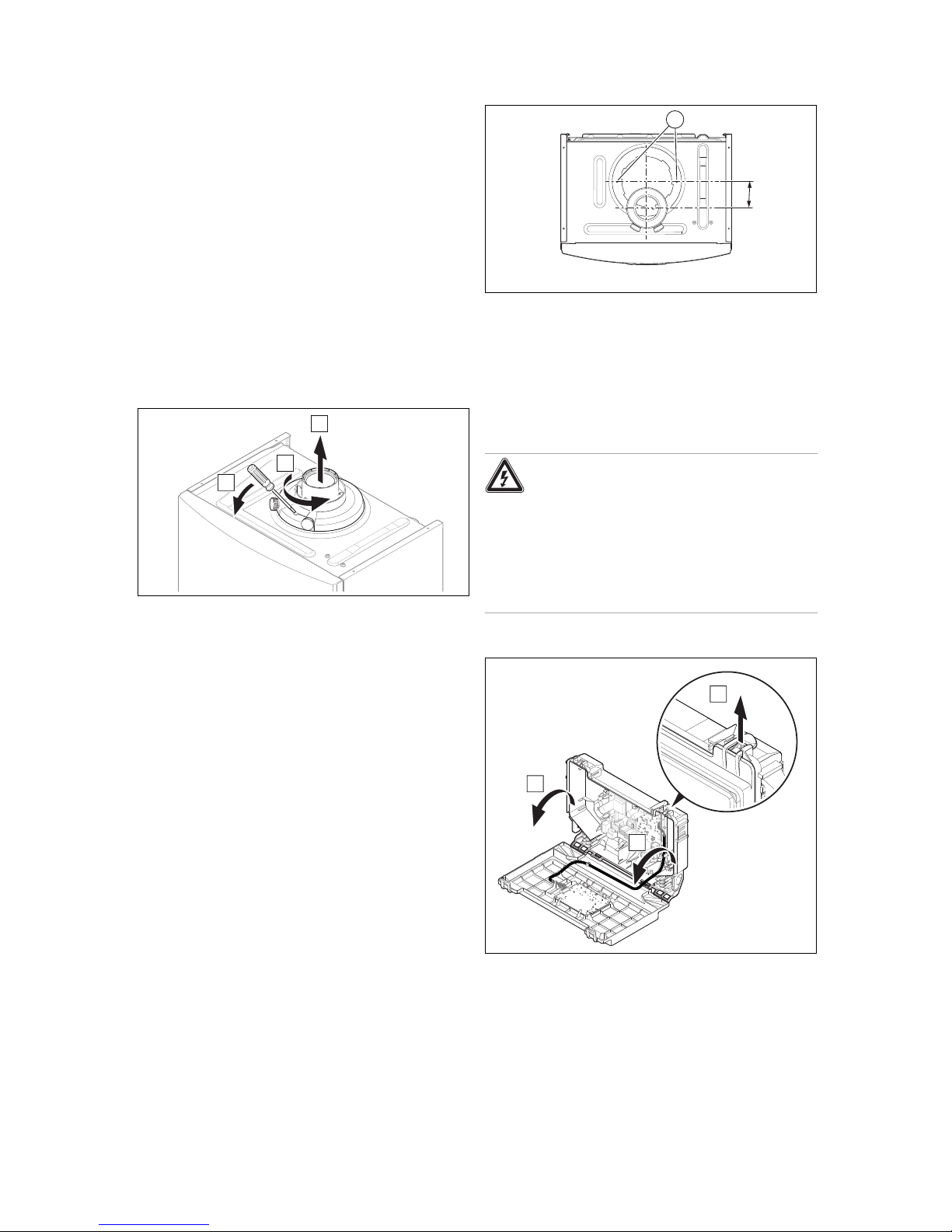
5.6.1 Opening the electronics box
B
B
A
▶ Open the electronics box as shown in the illustration.
Page 15
Installation 5
0020253094_01 ecoTEC sustain Installation and maintenance instructions 15
5.6.2 Cable route
1
2
1 24-V eBUS cable route
2 230-V eBUS cable route
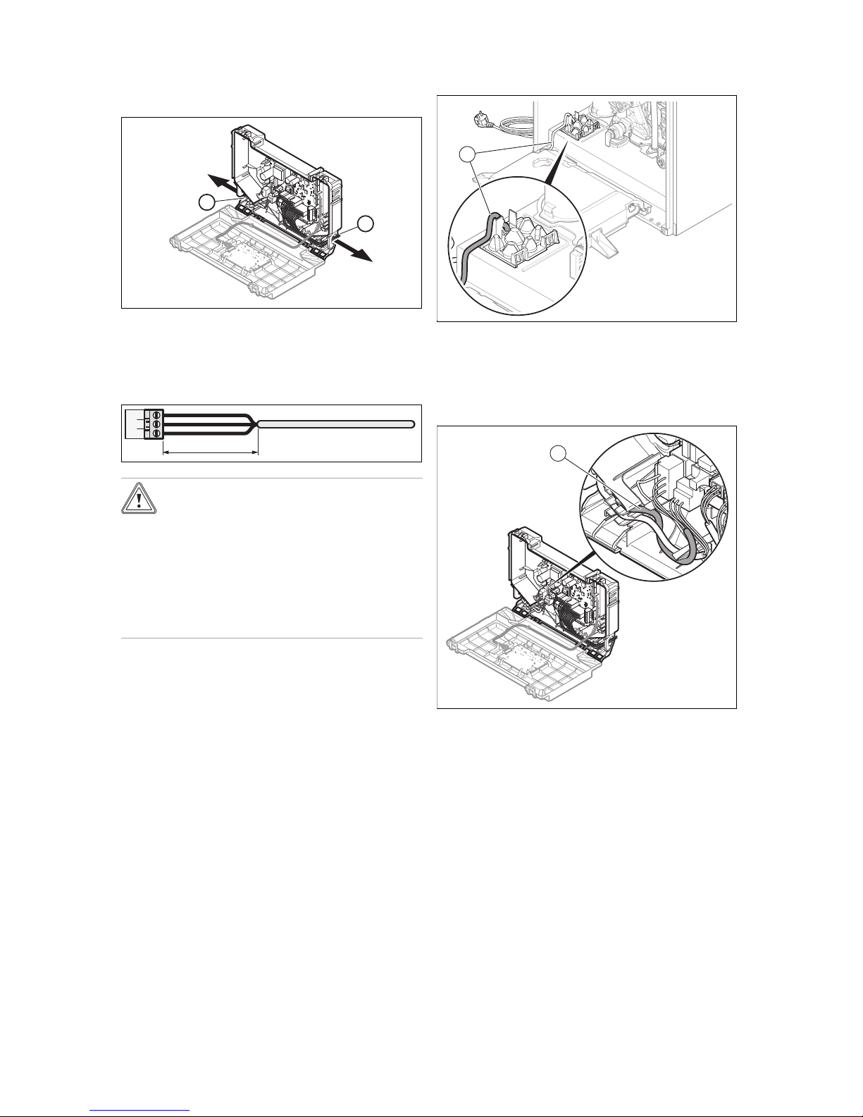
5.6.3 Wiring
30 mm max.
Caution.
Risk of material damage caused by incor-
rect installation.
Mains voltage at incorrect terminals and plug
terminals may destroy the electronics.
▶ Do not connect any mains voltage to the
eBUS terminals (+/-).
▶ Only connect the mains connection cable
to the terminals marked for the purpose.
1. Shorten the connection cables to the appropriate
lengths to prevent them from causing damage inside
the electronics box.
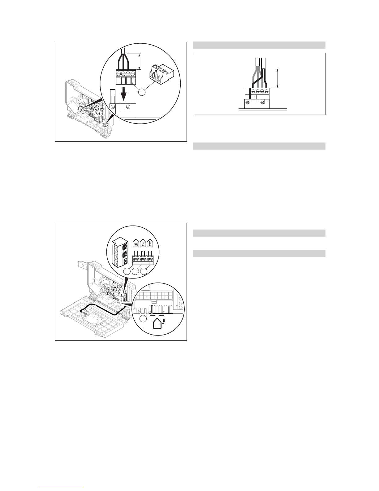
2. Screw the plug to the connection cable.
3. Plug the plug into the slot provided on the PCB.
5.6.4 Establishing the power supply
1. Observe all valid regulations.
– The applicable regulations state that the connection
must be made via an electrical partition with a contact opening of at least 3 mm at each pole.
– Power supply cable: Flexible line
2. Make sure that the rated voltage of the mains is 230 V.
1
3. Route a three-core power supply cable that complies
with the relevant standards through the grommet and
into the product.
4. Observe the routing of the power supply cable (1) in the
grommet in order to guarantee that there is no strain.
5. Open the electronics box. (→ Page 14)
1
6. Observe the flow of the power supply cable (1) in the
electronics box in order to guarantee that there is no
strain.
7. Provide one common electricity supply for the boiler
and for the corresponding controller:
– Power supply: Single-phase, 230 V, 50 Hz
– Fuse: ≤ 3 A
Page 16
6 Operation
16 Installation and maintenance instructions ecoTEC sustain 0020253094_01
≤ 30 mm
N
RT
230V~
X1
L
N
RT
L
1
8. Wire the unit. (→ Page 15)
9. Screw the supplied plug (1) to a three-core power supply cable that complies with the relevant standards.
10. Plug the plug for the power supply cable into a suitable
plug socket.
11. Make sure that access to the power supply is always
available and is not covered or blocked.
12. Close the electronics box.
5.6.5 Connecting controllers to the electronic
system
–
+
24V=
RT BUS
Burner
off
X106
BUS24 V
BUSRTB.off
Burn
er
o
f
f
R
T
24V =
-
+
BUS
X2
X41
X22
–
+
24V=
RT BUS
Burner
off
X106
1
2 3
4
1 Safety thermostat for
underfloor heating
2 24 V (ON/OFF) control
3 eBUS controller or radio
receiver unit
4 Outside temperature
sensor, wired
1. Open the electronics box (→ Page 14).
2. Wire the unit. (→ Page 15)
3. Connect the individual components depending on the
type of installation.
Conditions: If you are connecting a controller (230 V).
≤ 30 mm
NL
X1
230V~
RT
▶ Connect the controller to the main plug.
▶ Remove the bridge from the plug 24V=RT.
4. Close the electronics box.
Conditions: Connecting a limit thermostat for underfloor heating
▶ Remove the bridge and connect the limit thermostat to
the Burner off connection.
▶ Close the electronics box.
▶ For multi-circuit controllers (→ Page 17), change the
parameter d.18 from Eco (intermittently operating pump)
to Confort (continuously operating pump).
5.6.6 Connecting additional components via
VR 40 ("2 in 7" multi-functional module)
1. Install the components in accordance with the respect-
ive instructions.
Conditions: Components connected to relay 1
▶ Activate (→ Page 17) D.27.
Conditions: Components connected to relay 2
▶ Activate (→ Page 17) D.28.
6 Operation
6.1 Operating concept
The operating concept and the display and setting facilities
of the operator level are described in the operating instructions.
An overview of the display and setting options in the installer
level can be found in the section "Overview of the installer
level". (→ Page 17)
Page 17
Operation 6
0020253094_01 ecoTEC sustain Installation and maintenance instructions 17
6.2 Installer level overview
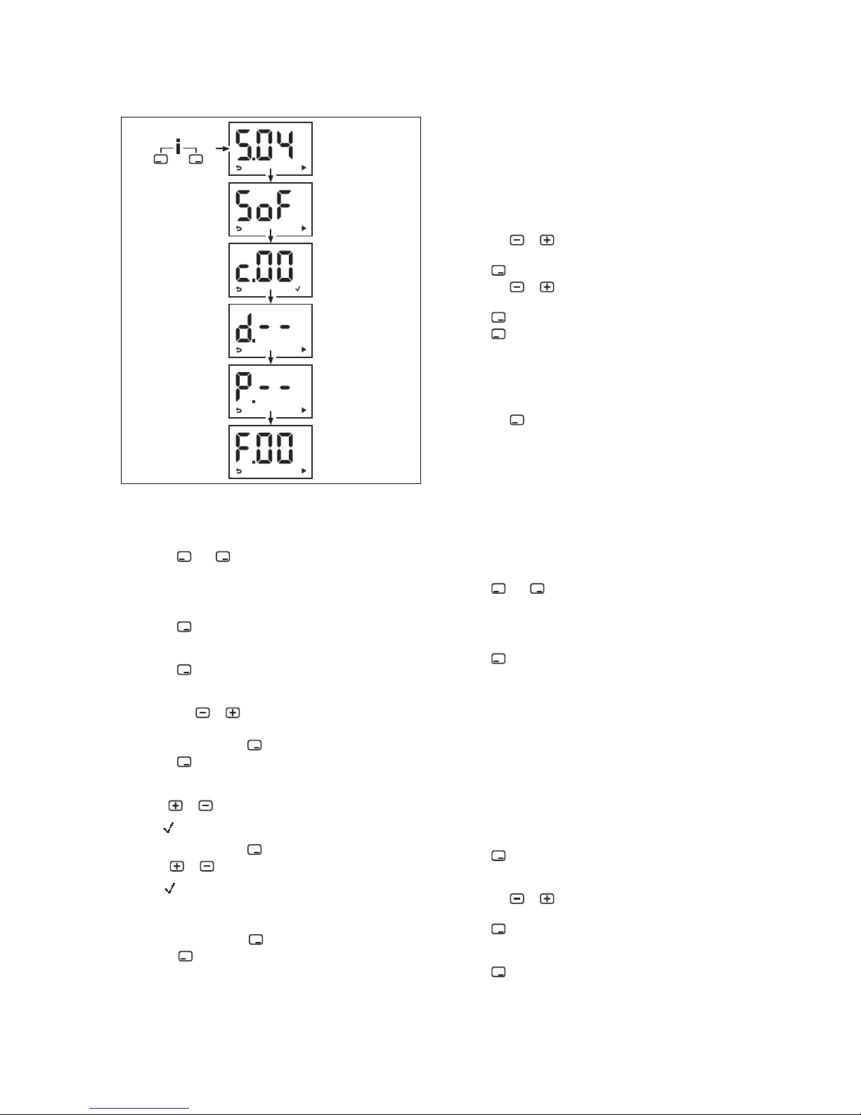
6.3 Calling up the installer level
1. Only call up the installer level if you are a competent
person.
2.
Press and ("i") at the same time.
◁ S.xx (current unit status) appears in the display,
followed by the heating flow temperature and the
heating installation pressure.
3.
Press to access the installer level.
◁ SoF and the software version appear in the display.
4.
Press .
◁ c.00 appears in the display.
5.
Press the or button to change the installer code.
– Installer code: 17
6.
Confirm by pressing .
7.
Press to access the diagnostics codes (d.), the
check programmes (P.) and the fault codes (F.) and to
return to the diagnostics codes (d.).
8.
Use or to set the required value .
◁
appears in the display.
9.
Confirm by pressing .
10.
Use or to set the required value .
◁
appears in the display if the value can be set.
◁ "no" appears in the display if the value cannot be
set.
11.
Confirm by pressing .
12.
Press to cancel a setting or exit the installer level.
6.4 Using diagnostics codes
You can use the parameters marked as adjustable in the
table of diagnostics codes to adapt the product to the system
and customer requirements.
6.4.1 Setting a diagnostics code
1. Call up the installer level. (→ Page 17)
◁ d.-- is shown in the display.
2.
Press the or button to select the diagnostics
code.
3.
Press to confirm.
4.
Press the or button to set the value of the diagnostic code.
5.
Press to confirm.
6.
Press to return to the sequence.
◁ The diagnostics codes are shown in the display
once again.
7. Proceed accordingly for all parameters that need to be
changed.
8.
Press the button 2 times to exit the diagnostics code
configuration.
◁ The display switches to the basic display.
6.5 Displaying the status codes
The status codes display the product's current operating
status.
Status codes – Overview (→ Page 38)
6.5.1 Live Monitor (status codes)
1.
Press and ("i") at the same time.
◁ The S.xx message appears in the display, followed
by information about the installation (→ Activating
access for the competent person).
2.
Press .
◁ The display switches to the basic display.
6.6 Using check programmes
By activating various check programmes, you can trigger
various special functions on the product.
Check programmes – Overview (→ Page 34)
6.6.1 Calling up the check programmes
1. Call up the installer level. (→ Page 17)
◁ d.-- is shown in the display.
2.
Press .
◁ P.-- is shown in the display.
3.
Press the or button to select the check
programme.
4.
Press to confirm.
◁ The check programme starts.
5.
Press .
Page 18

7 Start-up
18 Installation and maintenance instructions ecoTEC sustain 0020253094_01
◁ The heating water temperature and the filling pres-
sure for the heating installation are shown alternately in the display.
6.
Press to return to the check programme.
◁ The display shows the check programme.
7.
Press to exit the check programme.
◁ OFF is shown in the display.
◁ The display changes to show the check pro-
grammes.
8.
Press the button 2 times to exit the check
programme.
◁ The End message appears in the display.
◁ The display switches to the basic display.
7 Start-up
7.1 Carrying out the initial start-up
Initial start-up must be carried out by a customer service
technician or an authorised competent person using the firstcommissioning-checklist. The first-commissioning-checklist
in the appendix (→ Page 46) of the installation instructions
must be filled in and stored carefully along with the unit's
documentation.
▶ Carry out the initial start-up using the first-commission-
ing-checklist in the appendix.
▶ Fill out and sign the first-commissioning-checklist.
7.2 Gas type check
Make sure that the product is set up correctly by checking
the type of gas. This ensures optimum combustion quality.
▶ Check the type of gas as part of routine product mainten-
ance work when replacing components, carrying out work
on the gas route and carrying out a gas conversion.
7.3 Checking the factory setting
The product combustion is checked on-site and pre-set to
the type of gas specified on the identification plate.
▶ Check the information about the type of gas indicated on
the identification plate and compare this with the type of
gas available at the installation location.
Conditions: The product design is not compatible with the local type of
gas
You will require the conversion kit for the gas conversion;
this kit also contains the required conversion instructions.
▶ Follow the instructions in the manual for the conversion
kit to carry out the gas conversion on the product.
Conditions: The product design is compatible with the local type of gas
▶ Proceed in accordance with the description in these in-
structions.
7.4 Checking and treating the heating
water/filling and supplementary water
Caution.
Risk of material damage due to poor-qual-
ity heating water
▶ Ensure that the heating water is of suffi-
cient quality.
▶ Before filling or topping up the system, check the quality
of the heating water.
Checking the quality of the heating water
▶ Remove a little water from the heating circuit.
▶ Check the appearance of the heating water.
▶ If you ascertain that it contains sedimentary materials,
you must desludge the system.
▶ Use a magnetic rod to check whether it contains mag-
netite (iron oxide).
▶ If you ascertain that it contains magnetite, clean the sys-
tem and apply suitable corrosion-protection measures, or
fit a magnet filter.
▶ Check the pH value of the removed water at 25 °C.
▶ If the value is below 8.2 or above 10.0, clean the system
and treat the heating water.
▶ Ensure that oxygen cannot get into the heating water.
Checking the filling and supplementary water
▶ Before filling the system, measure the hardness of the
filling and supplementary water.
Treating the filling and supplementary water
▶ Observe all applicable national regulations and technical
standards when treating the filling and supplementary
water.
Provided the national regulations and technical standards
do not stipulate more stringent requirements, the following
applies:
You must treat the heating water in the following cases:
– If the entire filling and supplementary water quantity dur-
ing the operating life of the system exceeds three times
the nominal volume of the heating installation, or
– If the guideline values listed in the following table are not
met, or
– If the pH value of the heating water is less than 8.2 or
more than 10.0.
Total
heating
output
Water hardness at specific system volume
1)
≤ 20 l/kW
> 20 l/kW
≤ 50 l/kW
> 50 l/kW
kW
ppm
CaCO₃
mol/m³ppm
CaCO₃
mol/m³ppm
CaCO₃
mol/
m³
< 50 < 300 < 3 200 2 2 0.02
> 50
to ≤ 200
200 2 150 1.5 2 0.02
> 200
to ≤ 600
150 1.5 2 0.02 2 0.02
> 600 2 0.02 2 0.02 2 0.02
1) Nominal capacity in litres/heating output; in the case of multiboiler systems, the smallest single heating output is to be used.
Page 19

Start-up 7
0020253094_01 ecoTEC sustain Installation and maintenance instructions 19
Caution.
Risk of material damage if the heating
water is treated with unsuitable additives.
Unsuitable additives may cause changes in
the components, noises in heating mode and
possibly subsequent damage.
▶ Do not use any unsuitable frost and cor-
rosion protection agents, biocides or sealants.
No incompatibility with our products has been detected to
date with proper use of the following additives.
▶ When using additives, follow the manufacturer's instruc-
tions without exception.
We accept no liability for the compatibility of any additive or
its effectiveness in the rest of the heating system.
Additives for cleaning measures (subsequent
flushing required)
– Adey MC3+
– Adey MC5
– Fernox F3
– Sentinel X 300
– Sentinel X 400
Additives intended to remain permanently in the
system
– Adey MC1+
– Fernox F1
– Fernox F2
– Sentinel X 100
– Sentinel X 200
Additives for frost protection intended to remain
permanently in the system
– Adey MC ZERO
– Fernox Antifreeze Alphi 11
– Sentinel X 500
▶ If you have used the above-mentioned additives, inform
the operator about the measures that are required.
▶ Inform the operator about the measures required for frost
protection.
7.5 Preventing low water pressure
The required filling pressure is between 0.08 and 0.2 MPa
(0.8 and 2 bar).
If the water pressure falls below 0.05 MPa (0.5 bar), the
value flashes in the display.
If the water pressure falls below 0.03 MPa (0.3 bar), the
product switches off. The display shows 0.0 bar (0.0 MPa).
Fault F22 is stored in the fault list.
▶ Top up the water in the heating installation to start up the
product again.
◁ The pressure value flashes in the display until a
pressure of 0.05 MPa (0.5 bar) or higher has been
reached.
7.6 Filling the condensate siphon
A B
C
1
2
3
1. Unclip the lower section of the siphon (1) from the upper section of the siphon (2) without removing the product's front casing.
2. Remove the float (3).
3. Fill the lower section of the siphon with water up to 10
mm below the upper edge of the condensate discharge
pipe.
4. Reinsert the float (3).
Note
Check that the float is present in the condensate siphon.
5. Clip the lower section of the siphon (1) into the upper
section of the siphon (2).
7.7 Filling and purging the heating installation
Preliminary work
1. Flush the heating installation through.
2. Observe the information on the topic of treating
(→ Page 18) heating water.
1
1. Loosen the cap on the automatic air vent (1) by one or
two rotations.
2. Open all thermostatic radiator valves.
3. Supply the heating circuit with water.
4. Check whether the stop cocks for the heating flow and
return are open.
5. Start filling programme P.06.
Page 20

7 Start-up
20 Installation and maintenance instructions ecoTEC sustain 0020253094_01
Check programmes – Overview (→ Page 34)
◁ The diverter valve is moved to the mid-position.
6. Fill with water until the required filling pressure is
reached.
– Recommended filling pressure: 0.8 … 2 bar
◁ The heating and hot water function cannot be activ-
ated.
◁ The pressure value flashes in the display until a
pressure of 0.05 MPa (0.5 bar) or higher has been
reached.
◁ An automatic air vent function is activated if the
pressure exceeds 0.07 MPa (0.7 bar) for longer than
15 seconds.
7. Purge each radiator until the water escapes normally,
and then close the system's purging valves.
Note
Leave the cap on the pump's air vent valve
unscrewed.
8. Check whether all connections are leak-tight.
Conditions: If the noise persists in the boiler
▶ Purge the product again by activating check programme
P.00.
Check programmes – Overview (→ Page 34)
7.8 Filling the hot water circuit
1. Open the taps to fill the hot water circuit.
2. Close the taps once the required volume of water has
flowed into the circuit.
◁ The hot water circuit is filled.
3. Check all connections and the entire system for leaktightness.
7.9 Switching the product on and off
▶ Press the on/off button on the product.
◁ The basic display appears on the display.
7.10 Checking the gas settings
Only a qualified competent person is authorised to implement the CO2 setting on the gas valve assembly.
Never modify the factory setting of the gas pressure regulator of the gas valve.
7.10.1 Checking the gas flow rate
The gas flow rate has been set during production and does
not require adjustment. With the front casing fitted check the
gas flow rate of the boiler as follows:
▶ Start up the product with the check programme P.01.
▶ In addition, ensure that maximum heat can be dissipated
into the heating system by turning up the room thermostat.
▶ Wait at least 5 minutes until the boiler has reached its
operating temperature.
▶ Ensure that all other gas appliances in the property are
turned off.
▶ Measure the gas flow rate at the gas meter.
▶ Compare the measured values with the corresponding
values in the table.
Qnw from
the data
plate
H gas in m³/h P gas in m³/h
Nom.
+5%
−10% Nom.
+5%
−10%
24,4 2,58 2,71 2,32 1,90 2,00 1,71
28,5 3,02 3,17 2,72 2,21 2,32 1,99
34,6 3,66 3,84 3,29 2,69 2,82 2,42
Conditions: Gas flow rate not in the permissible range
▶ Check all of the piping and ensure that the gas flow rates
are correct.
▶ Only put the product into operation once the gas flow
rates have been corrected.
Conditions: Gas flow rate in the permissible range
▶ End the check programme P.01.
▶ Allow the boiler to cool down by allowing pump overrun to
operate for a minimum of 2 minutes.
▶ Record the boiler maximum gas flow rate onto the
Benchmark gas boiler commissioning checklist.
7.10.2 Checking the gas connection pressure (gas
flow pressure)
2
1
1. Ensure that the gas inlet working pressure can be
obtained with all other gas appliances in the property
working.
2. Close the gas isolator cock (1).
3. Undo the sealing screw on the measuring nipple (2).
4. Connect a pressure gauge to the measuring nipple (2).
5. Open the gas isolator cock (1).
6. Start up the product with check programme P.01.
7. In addition, ensure that maximum heat can be dissip-
ated into the heating system by turning up the room
thermostat.
8. With the boiler operating at full load check that the gas
inlet working pressure at the reference test point (2)
complies with the requirements.
Permissible connection pressure
Great Britain
Natural gas G20
1.7
… 2.0 kPa
(17.0
… 20.0 mbar)
Liquid gas G31
2.5
… 4.5 kPa
(25.0
… 45.0 mbar)
9. Should the pressure recorded at the reference test point
in the boiler be lower than indicated check if there is
Page 21

Start-up 7
0020253094_01 ecoTEC sustain Installation and maintenance instructions 21
any blockage in the pipework or if the pipework is undersized.
Conditions: Gas flow pressure not in the permissible range
Caution.
Risk of material damage and operating
faults caused by incorrect gas connection pressure.
If the gas connection pressure lies outside
the permissible range, this can cause operating faults in and damage to the product.
▶ Do not make any adjustments to the
product.
▶ Do not start up the product.
▶ If you cannot correct the failure, notify the gas supply
company and proceed as follows:
▶ End the check programme P.01 or P.04.
▶ Allow the boiler to cool down by allowing pump overrun
to operate for a minimum of two minutes.
▶ Close the gas isolator cock.
▶ Remove the pressure gauge and retighten the sealing
screw (2) for the measuring nipple.
▶ Open the gas isolator cock (1).
▶ Check the measuring nipple for gas tightness.
▶ Close the gas isolator cock (1).
▶ Disconnect the product from the power mains.
▶ You must not start up the boiler.
Conditions: Gas flow pressure in the permissible range
▶ End the check programme P.01 or P.04.
▶ Allow the boiler to cool down allowing pump overrun to
operate for a minimum of two minutes.
▶ Close the gas isolator cock (1).
▶ Remove the pressure gauge and retighten the sealing
screw (2) for the measuring nipple.
▶ Open the gas isolator cock (1).
▶ Check the measuring nipple for gas tightness.
▶ Reset boiler controls for normal operation.
▶ Record the appliance gas inlet working pressure (kPa
resp. mbar) in the Benchmark gas boiler commissioning
checklist.
7.10.3 Checking the leak-tightness of the flue gas
installation and flue gas recirculation
1. Check the flue gas installation is intact in accordance
with the latest gas safe technical bulletin and information supplied in the installation instructions.
2. For extended flue gas installations check for flue gas
recirculation using the air analysis point.
3. Use a flue gas analyser.
4. If you discover CO or CO2in the supply air, search for
the leak in the flue gas installation or for signs of flue
gas recirculation.
5. Eliminate the damage properly.
6. Check again whether the supply air contains any CO or
CO2.
7. If you cannot eliminate the damage, do not start up the
product.
7.10.4 Thoroughly flushing the heating installation
("hot")
1. Operate the appliance until the boiler and the heating
system are up to temperature.
2. Check the heating system for leaks.
3. Connect a hose to the drain valve located at the lowest
position of the heating system.
4. Shut off the boiler, open the drain valve and all purge
valves on the radiators and allow the water to flow out
of the heating system and the boiler quickly and fully.
5. Close the drain valve.
6. Re-fill the system until the system design pressure of
0,1 MPa (1,0 bar) is attained.
Note
The actual reading on the digital pressure
gauge should ideally be 0,05 MPa (0,5 bar)
plus an additional pressure corresponding
to the highest point of the system above the
base of the boiler – 10 m head equals an additional 1 bar reading on the pressure gauge.
The minimum pressure should not be less
than 0,1 MPa (1 bar) in any installation. If
the system is to be treated with an inhibitor it
should be applied at this stage in accordance
with the manufacturer’s instructions. Further
information can be obtained from Sentinel,
Betz Dearborn Ltd., Tel: 0151 420 9595, or
Fernox, Alpha– Fry technologies. Tel: 0870
8700362.
7. Fit the front panel.
7.10.5 Checking the CO₂ content
1. Start up the product with the check programme and set
the value.
– Setting value for the programme P.01: 100
Check programmes – Overview (→ Page 34)
2. Wait until the value that is read is stable.
– Waiting period for reading a stable value: 5 min
1
3. Unscrew the cover from the flue gas analysis point (1).
4. Measure the CO₂ content at the flue gas analysis point.
5. Compare the measured value with the corresponding
value in the table.
Page 22

8 Adapting the unit to the installation
22 Installation and maintenance instructions ecoTEC sustain 0020253094_01
Checking the CO₂ content
Great Britain
Fitted front casing
Natural
gas
Liquid
gas
G20 G31
9.2 ±1 % 10.4
±0.5 %
◁ The value is OK.
▽ The value is not OK; you cannot start up the
product.
▶ Contact customer service.
7.10.6 Performing gas conversion:
Note
You will need a conversion kit, which is available
separately.
The conversion procedure is described in the
manual supplied with the conversion kit.
▶ Follow the instructions in the manual for the conversion
kit to carry out the gas conversion on the product.
7.11 Checking leak-tightness
▶ Check the gas pipe, the heating circuit and the hot water
circuit for leak-tightness.
▶ Check that the air/flue pipe has been installed correctly.
Conditions: Room-sealed operation
▶ Check whether the vacuum chamber has been sealed so
that it is leak-tight.
7.11.1 Checking the hot water generation
1. Activate the hot water handling mode on the user
interface.
2. Open a hot water valve completely.
3. Call up the status codes. (→ Page 17)
Status codes – Overview (→ Page 38)
◁ If the product is working correctly, the display shows
S.14.
7.11.2 Checking the heating mode
1. Activate the heating mode on the user interface.
2. Turn all thermostatic radiator valves on the radiators
until they are fully open.
3. Allow the product to operate for at least 15 minutes.
4. Fill and purge the heating installation. (→ Page 19)
5. Call up the status codes. (→ Page 17)
Status codes – Overview (→ Page 38)
◁ If the product is working correctly, the display shows
S.04.
8 Adapting the unit to the installation
8.1 Activating diagnostics codes
You can find the setting options in the diagnostics codes in
the installer level.
▶ Set a diagnostics code. (→ Page 17)
8.2 Burner anti-cycling time
To prevent frequent switching on and off of the burner and
thus prevent energy losses, an electronic restart lockout
is activated for a specific period each time the burner is
switched off. The burner anti-cycling time is only active for
the heating mode. Switching on domestic hot water mode
during the burner anti-cycling time has no effect.
8.2.1 Setting the maximum burner anti-cycling
time
1. Set a diagnostics code. (→ Page 17)
T
Flow
(target)
[°C]
Set maximum burner anti-cycling time [min]
1 5 10 15 20 25 30
30 2.0 4.0 8.5 12.5 16.5 20.5 25.0
35 2.0 4.0 7.5 11.0 15.0 18.5 22.0
40 2.0 3.5 6.5 10.0 13.0 16.5 19.5
45 2.0 3.0 6.0 8.5 11.5 14.0 17.0
50 2.0 3.0 5.0 7.5 9.5 12.0 14.0
55 2.0 2.5 4.5 6.0 8.0 10.0 11.5
60 2.0 2.0 3.5 5.0 6.0 7.5 9.0
65 2.0 1.5 2.5 3.5 4.5 5.5 6.5
70 2.0 1.5 2.0 2.5 2.5 3.0 3.5
75 2.0 1.0 1.0 1.0 1.0 1.0 1.0
T
Flow
(target)
[°C]
Set maximum burner anti-cycling time
[min]
35 40 45 50 55 60
30 29.0 33.0 37.0 41.0 45.0 49.5
35 25.5 29.5 33.0 36.5 40.5 44.0
40 22.5 26.0 29.0 32.0 35.5 38.5
45 19.5 22.5 25.0 27.5 30.5 33.0
50 16.5 18.5 21.0 23.5 25.5 28.0
55 13.5 15.0 17.0 19.0 20.5 22.5
60 10.5 11.5 13.0 14.5 15.5 17.0
65 7.0 8.0 9.0 10.0 11.0 11.5
70 4.0 4.5 5.0 5.5 6.0 6.5
75 1.0 1.0 1.0 1.0 1.0 1.0
2. If required, adjust the maximum burner anti-cycling time
using diagnostics code d.02.
Page 23

Adapting the unit to the installation 8
0020253094_01 ecoTEC sustain Installation and maintenance instructions 23
8.2.2 Resetting the remaining burner anti-cycling
time
▶
Press and hold the button for more than three
seconds.
◁ All symbols are shown in the display.
8.3 Setting the maximum heating output
The product's maximum heating output is set to automatic
mode at the factory. If you want to set your own fixed maximum heating output, however, you can specify a value under d.00 which equates to the product output in kW.
8.4 Setting the maintenance interval
If you set the maintenance interval, after a configurable number of burner operating hours, the message that the product
must be serviced appears in the display, together with the
maintenance symbol .
▶ Use diagnostics code d.84 to set the number of operating
hours until the next maintenance is due (number of operating hours = display value x 10). Guideline values can
be found in the following table.
Heat demand
Number
of persons
Guideline value for burner
operating hours until the
next inspection/maintenance
work is due for an average
operating time of one year
(dependent upon the system
type)
5.0 kW
1 ‑ 2 1050 h
2 ‑ 3 1150 h
10.0 kW
1 ‑ 2 1500 h
2 ‑ 3 1600 h
15.0 kW
2 ‑ 3 1800 h
3 ‑ 4 1900 h
20.0 kW
3 ‑ 4 2600 h
4 ‑ 5 2700 h
25.0 kW
3 ‑ 4 2800 h
4 ‑ 6 2900 h
> 27.0 kW
3 ‑ 4 3000 h
4 ‑ 6 3000 h
The values stated correspond to an average operating time
of one year.
If you do not set a numerical value but do set the symbol
"– – –", the function is not active.
Note
On completion of the set operating hours, you
must set the maintenance interval again.
8.5 Setting the pump output
Applicability: VUW 246/7-2 (H-GB)
OR VUW 286/7-2 (H-GB)
OR VUW 346/7-2 (H-GB)
Conditions: Modulating pump
The product is equipped with a speed-regulated high-efficiency pump, which adjusts independently to the hydraulic
conditions of the heating installation.
If you have installed a low loss header in the heating installation, we recommend switching off the speed regulation and
setting the pump output to a fixed value.
▶ If required, use diagnostics code d.14 to adjust the set-
ting for the operating-mode-dependent pump speed.
▶ Set a diagnostics code. (→ Page 17)
Remaining feed head of the pump
Pump curve
Applicability: VUW 246/7-2 (H-GB)
OR VUW 286/7-2 (H-GB)
6
0 500 1000 1300
A
B
0
5
10
15
20
25
30
35
40
5
321 4
7
1 PWM 65%
2 PWM 73%
3 PWM 80%
4 PWM 88%
5 PWM 95 to 100%
6 Saturation 25 kPa
7 Saturation 17 kPa
A Throughput in circuit
(l/h)
B Available pressure
(kPa)
Pump characteristic line
Applicability: VUW 346/7-2 (H-GB)
6
0 500 1000 1400
A
B
0
5
10
15
20
25
30
35
40
5
321 4
7
1 PWM 65%
2 PWM 73%
3 PWM 80%
4 PWM 88%
5 PWM 95 to 100%
6 Saturation 25 kPa
Page 24

9 Troubleshooting
24 Installation and maintenance instructions ecoTEC sustain 0020253094_01
7 Saturation 17 kPa
A Throughput in circuit
(l/h)
B Available pressure
(kPa)
8.6 Setting the bypass
Conditions: D.14 is set to 0 = auto
Caution.
Risk of material damage caused by incor-
rect setting of the high-efficiency pump
When the pressure at the bypass is increased (turning clockwise), malfunctions
may occur if the pump output is set below
95%.
▶ In this case, set the pump output to 5 = 95
to 100% using diagnostics parameter
D.14.
▶ Do not change the factory settings.
Conditions: D.14 is set to 1–5
▶ Remove the front casing. (→ Page 11)
1
▶ Regulate the pressure using the adjusting screw (1).
Position of the
adjusting screw
Pressure
in MPa
(mbar)
Notes/application
Right-hand stop
(turned all the
way down)
0.035
(350)
If the radiators do not heat
up sufficiently at the default
setting. In this case, you
must set the pump to the
maximum speed.
Mid-position (six
anti-clockwise
rotations)
0.025
(250)
Default setting
Five further anticlockwise rotations starting from
the mid-position
0.017
(170)
If noises are produced in
the radiators or radiator
valves
▶ Fit the front panel.
8.7 Setting the hot water temperature
Danger!
Risk of death from Legionella.
Legionella multiply at temperatures below
60 °C.
▶ Ensure that the operator is familiar with all
of the Anti-legionella measures in order
to comply with the applicable regulations
regarding legionella prevention.
▶ Set the hot water temperature.
Conditions: Water hardness: > 3.57 mol/m³
– Hot water temperature: ≤ 50 ℃
8.8 Handing the product over to the operator
▶ When you have finished the installation, affix the en-
closed sticker (which requests that the user reads the
instructions) to the front of the product in the operator's
language.
▶ Explain to the operator how the safety devices work and
where they are located.
▶ Inform the operator how to handle the product.
▶ In particular, draw attention to the safety information
which the operator must follow.
▶ Inform the operator of the necessity to have the product
maintained according to the specified intervals.
▶ Pass all of the instructions and documentation for the
product to the operator for safe-keeping.
▶ Instruct the operator about measures taken to ensure the
supply of combustion air and flue gas pipe. Point out, in
particular, that the operator must not make any changes,
however minor.
▶ Inform the operator that they must not store or use ex-
plosive or highly flammable substances (such as petrol,
paper or paint) in the installation room of the product.
9 Troubleshooting
9.1 Checking service messages
appears, for example, if you have set a maintenance interval and this has passed or if a service message has been
issued. The product is not in fault mode.
▶ Call up the Live Monitor. (→ Page 17)
Conditions: S.46 is displayed.
The product is in Comfort protection mode. The product continues to run with restricted comfort after it has detected a
fault.
▶ To establish whether or not a component is defective,
read the fault memory. (→ Page 25)
Note
If no fault message is present, the product will
automatically switch back to normal operating
mode after a certain time.
Page 25

Troubleshooting 9
0020253094_01 ecoTEC sustain Installation and maintenance instructions 25
9.2 Rectifying faults
▶ If fault codes (F.XX) are present, refer to the table in the
appendix for advice or use the check programme(s).
Overview of fault codes (→ Page 39)
Check programmes – Overview (→ Page 34)
If several faults occur at the same time, the fault codes are
shown alternately on the display.
Resetting the product:
▶
Press and hold the button for more than three
seconds.
◁ The product restarts.
▶ If you are unable to clear the fault code and it reappears
despite several fault clearance attempts, contact customer service.
9.3 Calling up the fault memory
The last ten fault codes are stored in the fault memory.
▶ Call up the installer level. (→ Page 17)
◁ d.-- is shown in the display.
▶
Press the button 2 times.
◁ F.XX is shown in the display.
▶
Press the and buttons to call up the fault codes.
Overview of fault codes (→ Page 39)
◁ The fault code and the time of occurrence are shown
alternately on the display.
▶
Press .
◁ The display switches to the basic display.
9.4 Deleting the fault memory
1. Clear the fault memory using diagnostics code d.94.
2. Set a diagnostics code. (→ Page 17)
9.5 Resetting parameters to factory settings
1. Reset all parameters to the factory settings using diagnostics code d.96.
2. Set a diagnostics code. (→ Page 17)
9.6 Preparing the repair work
1. Decommission the product.
2. Disconnect the product from the power mains.
3. Remove the front casing. (→ Page 11)
4. Close the gas isolator cock.
5. Close the service valves in the heating flow and in the
heating return.
6. Close the service valve in the cold water pipe.
7. Drain the product to replace hydraulic components
(→ Page 30).
8. Ensure that water does not drip on live components
(e.g. the electronics box).
9. Use only new seals and o'ring. Do not use additional
compounds.
9.6.1 Procuring spare parts
The original components of the product were also certified
by the manufacturer as part of the declaration of conformity.
If you use other, non-certified or unauthorised parts during
maintenance or repair work, this may void the conformity of
the product and it will therefore no longer comply with the
applicable standards.
We strongly recommend that you use original spare parts
from the manufacturer as this guarantees fault-free and safe
operation of the product. To receive information about the
available original spare parts, contact the contact address
provided on the reverse of these instructions.
▶ If you require spare parts for maintenance or repair
work, use only the spare parts that are permitted for the
product.
9.7 Replacing defective components
9.7.1 Replacing the burner
1
2
1. Undo the four screws (1) on the burner.
2. Remove the burner.
3. Install a new seal (2) on the new burner.
Page 26

9 Troubleshooting
26 Installation and maintenance instructions ecoTEC sustain 0020253094_01
9.7.2 Replacing the fan or gas valve
7
4
3
2
1
6
9
8
5
1. Remove the air intake pipe.
2. Remove the plug from the gas valve (7).
3. Remove the plugs (6) and (9) from the fan motor by
pushing in the latching lug.
4. Unscrew the connection from the gas valve (8).
5. Unscrew the three screws (2)-(4) between the mixture
pipe (1) and the fan flange.
1
2
6. Remove the entire fan/gas valve unit from the product.
7. Unscrew both fixing screws (1) on the gas valve and
remove the fan from the gas valve.
8. Replace the defective fan or the defective gas valve.
9. Install the gas valve and the fan in the same position as
before. Use new seals for this.
10. Screw the fan to the gas valve.
11. If you had removed the gas pipe, screw the cap nut
of the gas pipe (2) only loosely to the gas valve. Only
tighten the cap nut on the gas valve after the installation work has been completed.
12. Refit the entire fan/gas valve unit in reverse order. You
must use a new seal (5) for this.
13. Ensure that the order in which the three screws are
screwed in between the fan and the mixture pipe corresponds to the numbering (3), (2) and (4).
14. Tighten the cap nut (2) on the gas valve and the cap
nut (8) between the gas pipes. In the process, secure
the gas pipe against twisting. Use new seals for this.
15. After you have completed this work, carry out a leaktightness test (function check). (→ Page 22)
16. If you have installed a new gas valve, adjust the gas
ratio setting. (→ Page 18)
9.7.3 Replacing the heat exchanger
1. Drain the product. (→ Page 30)
2. Detach the condensate drain hose from the heat ex-
changer.
3
2
1
3. Remove the clamps (2) and (3) from the area of the
flow and return connection.
4. Disconnect the flow connection.
5. Disconnect the return connection.
6. Remove both screws (1) from both brackets.
2
1
7. Remove the lower three screws (2) on the rear section
of the retainer.
8. Move the bracket round to the opposite side and attach
the upper screw (1) to the side.
9. Pull the heat exchanger downwards and to the right,
and remove it from the product.
10. Install the new heat exchanger in reverse order.
11. Replace the seals.
Note
Instead of grease, use only water or commercially available soft soap to aid installation.
Page 27

Troubleshooting 9
0020253094_01 ecoTEC sustain Installation and maintenance instructions 27
12. Insert the flow and return connections into the heat
exchanger as far as they will go.
13. Ensure that the clamps are correctly fitted to the flow
and return connections.
14. Fill and purge the unit and, if required, the heating system. (→ Page 19)
9.7.4 Replacing the expansion vessel
1
4
2
3
1. Prepare the repair work. (→ Page 25)
2. Undo the screwed connection (4).
3. Remove both screws (1) on the support plate (2).
4. Remove the support plate (2).
5. Pull out the expansion vessel (3) towards the front.
6. Insert the new expansion vessel into the product.
7. Screw the new expansion vessel to the water connec-
tion. Use a new seal for this.
8. Attach the support plate using both screws (1).
9. Fill and purge the product and, if required, the heating
installation (→ Page 19).
10. If necessary, adjust the pressure to the static height of
the heating installation.
11. Complete the repair work. (→ Page 28)
9.7.5 Replacing the main PCB
C
C
D
A
A
B
1. Prepare the repair work. (→ Page 25)
2. Open the electronics box. (→ Page 14)
3. Pull all of the plugs out from the PCB.
4. Undo the clips on the PCB.
5. Remove the PCB.
6. Install the new PCB in such a way that it clicks into the
groove at the bottom and into the clip at the top.
7. Plug in the PCB plugs.
8. Close the electronics box.
9. Complete the repair work. (→ Page 28)
9.7.6 Replacing the PCB for the user interface
C
D
A
A
B
1. Prepare the repair work. (→ Page 25)
2. Open the electronics box. (→ Page 14)
3. Pull the plug out of the PCB.
4. Undo the clips on the PCB.
5. Remove the PCB.
6. Install the new PCB in such a way that it clicks into the
groove at the bottom and into the clip at the top.
7. Plug in the PCB plug.
8. Close the electronics box.
9. Complete the repair work. (→ Page 28)
Page 28

10 Inspection and maintenance
28 Installation and maintenance instructions ecoTEC sustain 0020253094_01
9.7.7 Replacing the expansion relief valve
1
2
1. Remove the clip (2).
2. Remove the expansion relief valve.
3. Fit the new expansion relief valve with a new O-ring.
4. Reattach the clip (2).
9.7.8 Replacing the flow sensor
A
B
1
1. Pull out the plug.
2. Remove the flow sensor (1).
3. Install the new flow sensor.
4. Plug in the plug.
9.7.9 Replace the pressure sensor
1
2
1. Pull out the plug.
2. Remove the clip (1).
3. Remove the pressure sensor (2).
4. Install the new pressure sensor.
5. Reattach the clip (1).
9.7.10 Replacing the power supply cable
Note
The cable must be replaced by the manufacturer,
its customer service or suitably qualified persons
in order to avoid danger.
▶ If the power supply cable is damaged, replace it in ac-
cordance with the recommendations for the power supply
connection (→ Page 15).
– Section of the mains power cable: 3 G 0,75mm²
9.8 Completing repair work
1. Establish the power supply.
2. Switch the product back on if this has not yet been
done. (→ Page 20)
3. Install the front casing.
4. Open all service valves and the gas isolator cock.
10 Inspection and maintenance
10.1 Observing inspection and maintenance
intervals
Danger!
Risk of poisoning due to escaping flue
gases in overpressurised, multi-occupancy air/flue gas installations.
▶ Only perform maintenance and repair
work after you have shut down all of the
heat generators connected to the air/flue
gas installation.
▶ Use suitable means to seal the air/flue gas
connection for the air/flue gas installation
during maintenance and repair work.
▶ When replacing components, use only original seals sup-
plied, no additional sealants are necessary.
▶ Adhere to the minimum inspection and maintenance in-
tervals. The inspection may require maintenance to be
carried out earlier, depending on the results.
Inspection and maintenance work – Overview
(→ Page 43)
10.2 Checking and adjusting the gas ratio
setting
Only a qualified competent person is authorised to implement the CO2 setting on the gas valve assembly.
Each destroyed seal must be restored.
The CO2 adjusting screw must be sealed.
Never modify the factory setting of the gas pressure regulator of the gas valve.
Page 29

Inspection and maintenance 10
0020253094_01 ecoTEC sustain Installation and maintenance instructions 29
10.3 Checking the CO₂ content
1. Start up the product with the check programme (P.01)
and set the value.
– Setting value for the programme P.01: 100
Check programmes – Overview (→ Page 34)
2. Wait until the value that is read is stable.
– Waiting period for reading a stable value: 5 min
1
3. Unscrew the cover from the flue gas analysis point (1).
4. Measure the CO₂ content at the flue gas analysis point.
5. Compare the measured value with the corresponding
value in the table.
Checking the CO₂ content
Great Britain
Fitted front casing
Natural
gas
Liquid
gas
G20 G31
9.2 ±1 % 10.4
±0.5 %
◁ The value is OK.
▽ The value is not OK; you cannot start up the
product.
▶ Set the CO₂ content. (→ Page 29)
10.4 Setting the CO₂ content
Conditions: The CO₂ content must be adjusted
2
1
▶ Remove the sticker.
▶ Remove the covering cap (1).
▶ Turn the screw (2) to set the CO₂ content (value with
front casing removed).
◁ To increase the CO₂ content: Turn anti-clockwise
◁ To decrease the CO₂ content: Turn clockwise
Note
For natural gas only: Only perform the adjustment in small increments of a 1/8 turn and
wait approx. one minute after each adjustment until the value stabilises.
For liquid gas only: Only perform the adjustment in extremely small increments (approx.
1/16 turn), and wait approx. one minute after
each adjustment until the value stabilises.
▶ Compare the measured value with the corresponding
value in the table.
G20 – Setting the CO₂ value
Great Britain
Natural gas
Removed front
casing
Fitted front casing
G20 G20
CO₂ at full load
9.0 ±0.3 % 9.2 ±0.3 %
Set for Wobbe index W₀
14.09 kW⋅h/m³ 14.09 kW⋅h/m³
O₂ at full load
4.9 ±0.5 vol. % 4.5 ±0.5 vol. %
Page 30

10 Inspection and maintenance
30 Installation and maintenance instructions ecoTEC sustain 0020253094_01
Great Britain
Natural gas
Removed front
casing
Fitted front casing
G20 G20
CO at full load
≤ 250 ppm ≤ 250 ppm
CO/CO₂
≤ 0.0027 ≤ 0.0027
G31 – Setting the CO₂ value
Great Britain
Liquid gas
Removed front
casing
Fitted front casing
G31 G31
CO₂ at full load
10.2 ±0.3 % 10.4 ±0.3 %
Set for Wobbe index W₀
21.34 kW⋅h/m³ 21.34 kW⋅h/m³
O₂ at full load
5.4 ±0.4 vol. % 5.1 ±0.4 vol. %
CO at full load
≤ 250 ppm ≤ 250 ppm
CO/CO₂
≤ 0.0024 ≤ 0.0024
▽ If the setting is not in the specified adjustment range,
you must not start up the product.
▶ Contact customer service.
▶ Check whether the air-quality requirements with regard
to carbon monoxide are fulfilled.
▶ Refit the covering cap.
▶ Fit the front panel.
10.5 Preparing the maintenance work
1. Decommission the product.
2. Disconnect the product from the power mains.
3. Remove the front casing. (→ Page 11)
4. Close the gas isolator cock.
5. Close the service valves in the heating flow and in the
heating return.
6. Close the service valve in the cold water pipe.
7. Drain the product to clean hydraulic components
(→ Page 30).
8. Ensure that water does not drip on live components
(e.g. the electronics box).
9. Use only new seals and o'ring. Do not use additional
compounds.
10.6 Draining the product
1. Close the service valves of the product.
2. Start check programme P.06 (diverter valve mid-position).
3. Open the drain cock.
4. Make sure that the cap of the automatic air vent on
the internal pump is open so that the product can be
drained fully.
10.7 Removing the compact thermal module
Note
The compact thermal module consists of four
main components:
– Speed-regulated fan,
– Gas-air mixture unit,
– Gas supply (mixture pipe) with burner flange,
– Premix burner.
Danger!
Risk of death and risk of material damage
caused by hot flue gas.
The seal, insulating mat and self-locking nuts
on the burner flange must not be damaged.
Otherwise, hot flue gases may escape and
cause personal injury and material damage.
▶ Replace the seal each time you open the
burner flange.
▶ Replace the self-locking nuts on the
burner flange each time you open the
burner flange.
▶ If the insulating mat on the burner flange
or on the back wall of the heat exchanger
shows signs of damage, replace the insulating mat.
1. Switch off the product using the on/off button.
2. Close the gas isolator cock.
3. Remove the front casing.
4. Tilt the electronics box forwards.
2
1
3
5. Unscrew the retaining screw (1) and remove the air
intake pipe (2) from the intake stub.
6. Unscrew the cap nut from the gas valve (3).
Page 31

Inspection and maintenance 10
0020253094_01 ecoTEC sustain Installation and maintenance instructions 31
1
8
5
4
3
7
6
2
7. Remove the ignition line plug (3) and the earth line plug
(4) from the ignition electrode.
8. Remove the plugs (1) and (8) from the fan motor.
9. Remove the plug (2) from the gas valve.
10. Unscrew the four nuts (7).
11. Remove the entire compact thermal module (5) from
the heat exchanger (6).
12. Check the burner and the heat exchanger for damage
and dirt.
13. If necessary, clean or replace the components accord-
ing to the following sections.
14. Fit a new burner flange seal.
15. Check the insulating mat on the burner flange and on
the back wall of the heat exchanger. If you notice any
signs of damage, replace the relevant insulating mat.
10.8 Cleaning the heat exchanger
1. Protect the folded down electronics box against spraying water.
1
3
4
2
2. Do not undo the four nuts on the threaded pins (1), otherwise the tightness of the burner during set-up cannot
be guaranteed.
3. Clean the spiral immersion heater (3) of the heat exchanger (4) using water or, if required, vinegar (up to a
maximum acid content of 5%). Allow the vinegar to act
on the heat exchanger for 20 minutes.
4. Rinse away any loose dirt with a sharp jet of water or
use a plastic brush. Do not point the jet of water directly at the insulating mat (2) on the back of the heat
exchanger.
◁ The water flows out of the heat exchanger through
the condensate siphon.
10.9 Checking the burner
1
2
3
1. Check the surface of the burner (1) for damage. If any
damage is found, replace the burner.
2. Fit a new burner flange seal (3).
3. Check the insulating mat (2) on the burner flange. If you
discover any signs of damage, replace the insulating
mat.
10.10 Checking the ignition electrode
1
2
3
4
5
6
1. Disconnect the connection (2) and the earthing cable
(1).
2. Remove the fixing screws (3).
3. Carefully remove the electrode (4) from the combustion
chamber.
4. Ensure that the electrode ends (6) are undamaged.
5. Clean and check the gap between the electrodes.
Page 32

10 Inspection and maintenance
32 Installation and maintenance instructions ecoTEC sustain 0020253094_01
– Distance between the ignition and flame control
electrodes: 3.5 … 4.5 mm
6. Make sure that the seal (5) is free from damage.
▽ If necessary, replace the seal.
10.11 Cleaning the condensate siphon
A B
C
1
2
3
1. Unclip the lower section of the siphon (1) from the upper section of the siphon (2).
2. Remove the float (3).
3. Flush out the float and lower section of the siphon with
water.
4. Fill the lower section of the siphon with water up to 10
mm below the upper edge of the condensate drain pipework.
5. Re-insert the float (3).
Note
Check that the float is present in the condensate siphon.
6. Clip the lower section of the siphon (1) into the upper
section of the siphon (2).
10.12 Cleaning the filter in the cold water inlet
Applicability: Product with integrated hot water generation
1. Close the main cold water line.
2. Drain the product on the hot water side.
3. Remove the connection piece from the connection for
the product's cold water supply.
4. Clean the filter in the cold water inlet without removing
it.
10.13 Cleaning the heating filter
1
2
3
2
5
4
1. Drain the product. (→ Page 30)
2. Remove the temperature sensor (3).
3. Remove the upper clip (1).
4. Remove the lower clip (4).
5. Remove the supply pipe (2).
6. Remove the heating filter (5) and clean it.
7. When reinstallling the components, carry out the steps
described above in reverse.
10.14 Installing the compact thermal module
1
8
5
4
3
7
6
2
1. Connect the compact thermal module (5) to the heat
exchanger (6).
2. Tighten the four nuts (7) in a cross-wise pattern until the
burner flange fits closely and uniformly onto the mating
surfaces.
Page 33

Decommissioning 11
0020253094_01 ecoTEC sustain Installation and maintenance instructions 33
– Tightening torque: 6 Nm
3. Reconnect the plugs (1) to (4) and (8).
4. Connect the gas pipe using a new seal. In the process,
secure the gas pipe against twisting.
5. Open the gas isolator cock.
6. Make sure that there are no leaks.
7. Check that the sealing ring in the air intake pipe is positioned correctly in the seal seat.
8. Reconnect the air intake pipe to the intake nozzle.
9. Secure the air intake pipe with the retaining screw.
10. Check the gas flow pressure.
10.15 Checking the product for leak-tightness
▶ Check that the product is leak-tight. (→ Page 22)
10.16 Checking the admission pressure of the
expansion vessel
1. Drain the product. (→ Page 30)
2. Measure the pre-charge pressure of the expansion vessel at the vessel valve.
Conditions: Pre-charge pressure < 0.075 MPa (0.75 bar)
▶ Fill the expansion vessel in accordance with the static
height of the heating installation; ideally with nitrogen,
otherwise with air.
▶ Ensure that the drain valve is open when filling.
3. If water escapes from the valve of the expansion vessel, replace the expansion vessel (→ Page 27).
4. Fill and purge the heating installation. (→ Page 19)
10.17 Completing inspection and maintenance
work
Once you have completed all maintenance work:
▶ Check the CO₂ content. (→ Page 29)
▶ If required, reset (→ Page 23)the maintenance interval.
11 Decommissioning
11.1 Permanently decommissioning the product
▶ Press the on/off button.
◁ The display goes out.
▶ Disconnect the product from the power mains.
▶ Close the gas isolator cock.
▶ Close the cold water stop valve.
▶ Drain the product. (→ Page 30)
12 Recycling and disposal
Disposing of the packaging
▶ Dispose of the packaging correctly.
▶ Observe all relevant regulations.
13 Customer service
To ensure regular servicing, it is strongly recommended
that arrangements are made for a Maintenance Agreement.
Please contact Vaillant Service Solutions for further details:
Telephone: 0330 100 3461
Page 34

Appendix
34 Installation and maintenance instructions ecoTEC sustain 0020253094_01
Appendix
A Check programmes – Overview
Display Meaning
P.00 Purging the hot water and heating circuit:
The function is activated in the small hot water circuit for three minutes and then in the heating circuit for one
minute.
The pump runs and stops at regular intervals.
If required, this function can be manually switched off.
P.01 The burner operates with an adjustable heat load in heating or domestic hot water mode:
The product operates after ignition with the heat input set between "0" (0% = Pmin) and "100" (100% = Pmax).
The function is active for 15 minutes.
P.02 The burner operates at ignition load in heating or domestic hot water mode:
After ignition, the product works at ignition load.
The function is active for 15 minutes.
P.06 Filling the product:
The diverter valve is moved to the mid-position. The burner and pump switch off (to fill or drain the product).
Automatic air vent
function
Purging the product:
If the pressure is lower than 0.03 MPa (0.3 bar) for longer than 15 seconds and then is above 0.07 MPa (0.7
bar), the automatic purging function is activated.
The function is activated in the small hot water circuit for four minutes and then in the heating circuit for six
minutes.
This function cannot be manually switched off.
B Overview of diagnostics codes
Note
Since the code table is used for various products, some codes may not be visible for the product in question.
Diagnostics
code
Parameter
Values
Unit Increment, select, explanation
Default setting
Own setting
Min. Max.
d.00 Maximum heating output
is fixed or adjusts automatically
– – kW The maximum heating output
varies depending on the product.
→ Section "Technical data"
Automatic: Unit automatically
adjusts the maximum output to
the current system demand
→ Section
"Technical
data"
Adjustable
d.01 Pump overrun in heating
mode
1 60 min 1 5 Adjustable
d.02 Maximum burner anti-
cycling time in heating
mode
2 60 min 1 20 Adjustable
d.04 Water temperature in the
cylinder
Current value ℃ Applies to: Product with heat-
ing mode only, connected to domestic hot water cylinder with
temperature sensor
– Not
adjustable
d.05 Determined heating flow
set target temperature
Current value
℃ – – Not
adjustable
d.06 Hot water set target tem-
perature
Current value ℃ Applies to: Combi boiler – Not
adjustable
d.07 Set target temperature
for the domestic hot water cylinder
Current value ℃ Applies to: Product with heat-
ing mode only, connected to domestic hot water cylinder with
temperature sensor
– Not
adjustable
d.08 Status of the 230 V room
thermostat (ON/OFF)
Current value – 0 = Room thermostat open (no
heat requirement)
1 = Room thermostat closed
(heat requirement)
– Not
adjustable
Page 35

Appendix
0020253094_01 ecoTEC sustain Installation and maintenance instructions 35
Diagnostics
code
Parameter
Values
Unit Increment, select, explanation
Default setting
Own setting
Min. Max.
d.09 Heating flow set target
temperature that is set
on the eBUS room thermostat
Current value ℃ – – Not
adjustable
d.10 Status of the internal
pump in the heating circuit
Current value – off / on – Not
adjustable
d.11 Status of the heating
circuit's shunt pump
Current value – Applies to: Installed heating cir-
cuit shunt pump (optional)
off / on
– Not
adjustable
d.13 Status of the hot water
circuit's circulation pump
Current value – Applies to: Installed hot water
circuit circulation pump (optional)
off / on
– Not
adjustable
d.14 Operating mode of the
modulating pump
0 5 – 0 = Speed-regulated (automatic
pump operation in levels 1 to 5)
1 = PWM = 65 %
2 = PWM = 73 %
3 = PWM = 80 %
4 = PWM = 88 %
5 = PWM = 95 %
1; 2; 3; 4; 5 = Fixed rotational
speeds → Section "Setting the
pump output"
0 Adjustable
d.15 Pump speed Current value % – – Not
adjustable
d.16 Status of the 24 V room
thermostat
Current value – off = Heating off
on = Heating activated or eBUS
controller used
– Not
adjustable
d.17 Heating control – – – off = Flow temperature
on = Return temperature (adjustment for underfloor heating.
If you have activated the return
temperature control, the automatic heating output determination function is not active.)
0 Adjustable
d.18 Pump overrun operating
mode
1 3 – 1 = Comfort (continuously operat-
ing pump)
3 = Eco (pump runs intermittently)
3 Adjustable
d.20 Maximum hot water set
target temperature
50 60 ℃ 1 60 Adjustable
d.21 Status of the warm start
for hot water
Current value – off = Function deactivated
on = Function activated and
available
– Not
adjustable
d.22 Status of the domestic
hot water demand
Current value – off = No current requirement
on = Current requirement
– Not
adjustable
d.23 Status of the heating
demand
Current value – off = Heating off (Summer mode)
on = Heating on
– Not
adjustable
d.25 Status of the requirement
to reheat the cylinder or
for the hot water warm
start from the eBUS thermostat
Current value – off = Function deactivated
on = Function activated
– Not
adjustable
Page 36

Appendix
36 Installation and maintenance instructions ecoTEC sustain 0020253094_01
Diagnostics
code
Parameter
Values
Unit Increment, select, explanation
Default setting
Own setting
Min. Max.
d.27 Function of relay 1
(multi-functional module)
1 10 – 1 = Circulation pump
2 = External pump
3 = Cylinder charging pump
4 = Extractor hood
5 = External solenoid valve
6 = External fault message
7 = Solar pump (omitted)
8 = eBUS remote control
9 = Legionella protection pump
10 = Solar valve
1 Adjustable
d.28 Function of relay 2
(multi-functional module)
1 10 – 1 = Circulation pump
2 = External pump
3 = Cylinder charging pump
4 = Extractor hood
5 = External solenoid valve
6 = External fault message
7 = Solar pump (omitted)
8 = eBUS remote control
9 = Legionella protection pump
10 = Solar valve
2 Adjustable
d.33 Fan speed target value Current value rpm Fan speed = Display value x 100 – Not
adjustable
d.34 Value for the fan speed Current value rpm Fan speed = Display value x 100 – Not
adjustable
d.35 Position of the prioritising
diverter valve
Current value – 0 = Heating
40 = Mid-position (frost protection
or filling)
100 = Domestic hot water
– Not
adjustable
d.36 Value for the hot water
flow
Current value l/min Applies to: Combi boiler – Not
adjustable
d.39 Water temperature in the
solar circuit
Current value ℃ Applies to: Installed solar set
(optional)
– Not
adjustable
d.40 Heating flow temperature Current value ℃ – – Not
adjustable
d.41 Heating return temperat-
ure
Current value ℃ – – Not
adjustable
d.47 Outdoor temperature Current value ℃ – – Not
adjustable
d.50 Correction of the min-
imum fan speed
300 1500 rpm 1
Fan speed = Display value x 10
600 Adjustable
d.51 Correction of the max-
imum fan speed
-1500 -500 rpm 1
Fan speed = Display value x 10
-1000 Adjustable
d.58 Solar circuit reheating 0 3 – Applies to: Installed solar set
(optional)
0 = Product's anti-legionella function deactivated
3 = Hot water activated (min.
target value 60 °C)
0 Adjustable
d.60 Number of blocks by the
temperature limiter (limit
temperature)
Current value – – – Not
adjustable
d.61 Number of unsuccessful
ignitions
Current value – – – Not
adjustable
d.64 Average burner ignition
time
Current value s – – Not
adjustable
d.65 Maximum burner ignition
time
Current value s – – Not
adjustable
d.66 Activation of the warm
start function for hot water
– – – off = Function deactivated
on = Function activated
1 Adjustable
Page 37

Appendix
0020253094_01 ecoTEC sustain Installation and maintenance instructions 37
Diagnostics
code
Parameter
Values
Unit Increment, select, explanation
Default setting
Own setting
Min. Max.
d.67 Remaining burner anti-
cycling time (setting under d.02)
Current value min – – Not
adjustable
d.68 Number of unsuccessful
ignitions at 1st attempt
Current value – – – Not
adjustable
d.69 Number of unsuccessful
ignitions at 2nd attempt
Current value – – – Not
adjustable
d.71 Maximum heating flow
set target temperature
30 80 ℃ 1 → Section
"Technical
data"
Adjustable
d.73 Correction of the hot wa-
ter warm start temperature
-15 5 K Applies to: Combi boiler
1
0 Adjustable
d.75 Maximum cylinder re-
heating time
20 90 min Applies to: Product with heating
mode only
1
45 Adjustable
d.77 Max. cylinder reheating – – kW Applies to: Product with heating
mode only
1
→ Section "Technical data"
– Adjustable
d.80 Running time in heating
mode
Current value h Running time = Display value x
100
– Not
adjustable
d.81 Running time in domestic
hot water mode
Current value h Running time = Display value x
100
– Not
adjustable
d.82 Number of burner igni-
tions in heating mode
Current value – Number of ignitions = Display
value x 100
– Not
adjustable
d.83 Number of burner igni-
tions in domestic hot water mode
Current value – Number of ignitions = Display
value x 100
– Not
adjustable
d.84 Maintenance in 0 3000 h Number of hours = Display value
x 10
_ _ _ Not
adjustable
d.85 Increase in the min. out-
put (heating and domestic hot water mode)
– – kW 1 – Adjustable
d.88 Flow rate limit value for
ignition in domestic hot
water mode
0 1 – Applies to: Combi boiler
0 = 1.5 l/min (no delay)
1 = 3.7 l/min (2 s delay)
0 Adjustable
d.90 Status of the eBUS room
thermostat
Current value – off = Not connected
on = Connected
– Not
adjustable
d.91 Status DCF77 Current value – – – Not
adjustable
d.93 Setting the product code 0 99 – 1
The Device Specific Number
(DSN) can be found on the identification plate.
– Adjustable
d.94 Delete fault list 0 1 – 0 = No
1 = Yes
– Adjustable
d.95 Software versions – – – 1 = Main PCB
2 = Interface PCB
– Not
adjustable
d.96 Default setting (reset) 0 1 – 0 = No
1 = Yes
– Adjustable
Page 38

Appendix
38 Installation and maintenance instructions ecoTEC sustain 0020253094_01
C Status codes – Overview
Note
Since the code table is used for various products, some codes may not be visible for the product in question.
Status code Meaning
Displays in heating mode
S.00 Heating mode: No requirement
S.01 Heating mode: Advance fan operation
S.02 Heating mode: Pump pre-run
S.03 Heating mode: Burner ignition
S.04 Heating mode: Burner on
S.05 Heating mode: Pump/fan overrun
S.06 Heating mode: Fan overrun
S.07 Heating mode: Pump overrun
S.08 Heating mode: Temporary shutdown after heating procedure
Displays in hot water handling mode
S.10 Hot water handling mode: Requirement
S.11 Hot water handling mode: Advance fan operation
S.13 Hot water handling mode: Burner ignition
S.14 DHW mode: Burner on
S.15 DHW mode: Pump/fan overrun
S.16 DHW mode: Fan overrun
S.17 DHW mode: Pump overrun
Display in Comfort mode with warm start or hot water handling mode with cylinder
S.20 Hot water handling mode: Requirement
S.21 Hot water handling mode: Advance fan operation
S.22 Hot water handling mode: Pump pre-run
S.23 Hot water handling mode: Burner ignition
S.24 DHW mode: Burner on
S.25 DHW mode: Pump/fan overrun
S.26 DHW mode: Fan overrun
S.27 DHW mode: Pump overrun
S.28 Hot water handling mode: Temporary shutdown of the burner
Other displays
S.30 Room thermostat is blocking heating mode.
S.31 No heating demand: Summer mode, eBUS controller, waiting period
S.32 Fan waiting time: Fan speed outside of the tolerance values
S.34 Frost protection active
S.39 Underfloor heating contact open
S.42 Accessory fault: Flue non-return flap closed or condensate pump fault
S.53 Product in waiting period/operation block function due to low water pressure (flow/return spread too large)
S.54 Waiting period: Low water pressure in the circuit (flow/return spread too large)
S.88 Product purging active
S.91 Maintenance: Operating display demo mode
S.96 Automatic test programme: Flow and return temperature sensors, heating and hot water requests blocked or
product fault.
S.98 Automatic test programme: Return temperature sensor, heating and hot water requests blocked.
S.108 Purging the combustion chamber, fan in operation
S.109 Product's standby mode activated
Page 39

Appendix
0020253094_01 ecoTEC sustain Installation and maintenance instructions 39
D Overview of fault codes
Note
Since the code table is used for various products, some codes may not be visible for the product in question.
If faults occur, some of them can be reset. To do so, press and hold the button for three seconds.
Fault code Meaning Possible cause
F.00 Fault: Flow temperature sensor NTC plug not plugged in or has come loose, multiple plug on the PCB not
plugged in correctly, interruption in cable harness, NTC sensor defective
F.01 Fault: Return temperature sensor NTC plug not plugged in or has come loose, multiple plug on the PCB not
plugged in correctly, interruption in cable harness, NTC sensor defective
F.10 Short circuit: Flow temperature sensor NTC sensor defective, short circuit in the cable harness, cable/housing
F.11 Short circuit: Return temperature sensor NTC sensor defective, short circuit in the cable harness, cable/housing
F.13 Short circuit: Domestic hot water cylinder
temperature sensor
Applies to: Product with heating mode only
NTC sensor defective, short circuit in the cable harness, cable/housing
F.20 Safety shutdown: Overheating temperat-
ure reached
Overheating temperature reached; check whether water is available and
whether the flow rate is sufficient.
Incorrect earth connection between cable harness and product, flow or return
NTC defective (loose connection), stray spark via ignition cable, ignition plug
or ignition electrode
F.22 / 0,0
bar
Safety shutdown: Low water pressure in
the boiler
No water or insufficient water in the product, water pressure sensor defective, cable to water pressure sensor loose/not connected/defective
F.23 Safety shutdown: Temperature spread
too great (NTC1/NTC2)
Pump blocked, insufficient pump output, air in product, flow and return NTC
sensors connected the wrong way round
F.24 Safety shutdown: Temperature rise too
fast
Pump blocked, insufficient pump output, air in product, system pressure too
low, non-return valve blocked/incorrectly installed
F.27 Safety shutdown: Fault in flame detec-
tion
Moisture on the electronics, electronics (flame monitor) defective, gas solenoid valve leaking
F.28 Fault: Ignition unsuccessful when startingupGas meter defective or gas pressure monitor has triggered, air in gas, gas
flow pressure too low, thermal isolator device (TAE) has triggered, incorrect
gas injector, incorrect spare gas valve assembly, fault on the gas valve assembly, multiple plug on PCB incorrectly plugged in, break in cable harness,
ignition system (ignition transformer, ignition cable, ignition plug, ignition
electrode) defective, ionisation flow interrupted (cable, electrode), incorrect
earthing of product, electronics defective
F.29 Fault: Flame loss Gas supply temporarily stopped, flue gas recirculation, incorrect earthing of
product, ignition transformer has spark failure
F.32 Fan test function active: Fan speed
outside the tolerance values
Plug on fan not correctly plugged in, multiple plug on PCB not correctly
plugged in, break in cable harness, fan blocked, Hall sensor defective, electronics defective
F.46 Short circuit: Temperature sensor at the
solar circuit water inlet
Applies to: Installed solar set (optional)
Sensor defective, short circuit in the cable harness, cable/housing
F.49 eBUS fault: Voltage too low Short circuit on the eBUS, eBUS overload or two power supplies with differ-
ent polarities on the eBUS (can only be found in the fault report)
F.61 Fault: Gas valve assembly control sys-
tem
Short circuit/short to earth in cable harness for the gas valve assembly, gas
valve defective assembly (coils shorted to earth), electronics defective
F.62 Fault: Gas valve switch-off control Delayed switch-off of gas valve assembly, delayed extinguishing of flame
signal, gas valve assembly leaking, electronics defective
F.63 Fault: EEPROM Electronics defective
F.64 Fault: Electronics/sensor/analogue-to-
digital converter
Flow or return NTC short circuited, electronics defective
F.65 Fault: Electronics temperature too high Electronics overheating due to external influences, electronics defective
F.67 Value sent back by ASIC is incorrect
(flame signal)
Implausible flame signal, electronics defective
F.68 Fault: Unstable flame (analogue input) Air in gas, gas flow pressure too low, incorrect air ratio, incorrect gas in-
jector, ionisation flow interruption (cable, electrode)
Electronics defective
F.70 Invalid product code (DSN) Replace the screen and PCB at the same time without reconfiguring the
product's Device Specific Number
Page 40

Appendix
40 Installation and maintenance instructions ecoTEC sustain 0020253094_01
Fault code Meaning Possible cause
F.71 Fault: Flow/return temperature sensor Flow temperature sensor specifies a constant value: Flow temperature
sensor incorrectly attached to the flow pipe, flow temperature sensor defective
F.72 Fault: Deviation in the water pressure
sensor/return temperature sensor
Flow/return NTC temperature difference too great → flow and/or return temperature sensor defective
F.73 Fault: Water pressure sensor not con-
nected or has short-circuited
Interruption/short circuit of water pressure sensor, interruption/short to earth
in supply line to water pressure sensor or water pressure sensor defective
F.74 Fault: Electrical problem in the water
pressure sensor
Line to water pressure sensor has a short circuit to 5 V/24 V or internal fault
in the water pressure sensor
F.77 Fault: Condensate or smoke Applies to: Installed condensate pump or flue non-return flap (optional)
Check the defective condensate pump or flue non-return flap
F.83 Fault: Dry fire When the burner starts, the temperature change recorded by the flow or
return temperature sensor is non-existent or too small: Insufficient water in
the product, flow or return temperature sensor incorrectly attached to the
pipe
F.84 Fault: Flow/return temperature sensor Values not consistent, difference between flow and return < -6 K
Flow and return temperature sensors signalling implausible values: Flow and
return temperature sensors have been inverted, flow and return temperature
sensors have not been correctly installed
F.85 Fault: Temperature sensor The flow and/or return temperature sensors have been installed on the same
pipe/incorrect pipe
Temperature sensor not connected or is connected incorrectly
F.87 Fault: Ignition transformer cable Ignition transformer cable harness not connected to the main PCB or it is
connected incorrectly, short circuit in the cable harness or damaged ignition
transformer
F.88 Fault: Gas valve assembly Gas valve assembly not connected or it is connected incorrectly, short circuit
in the cable harness
F.89 Fault: Pump Pump not connected or it is connected incorrectly, incorrect pump connec-
ted, short circuit in the cable harness
Err Fault: Interface communication Interface PCB not connected or connected incorrectly, short circuit in the
cable harness
Page 41

Appendix
0020253094_01 ecoTEC sustain Installation and maintenance instructions 41
E Wiring diagrams
E.1 Wiring diagram
Applicability: VUW 246/7-2 (H-GB), VUW 286/7-2 (H-GB)
X2
X14
L
N
19
10
20
2
6
3
11
13
14
18
7
17
8
X51
X51
X20
16
1
9
3
15
4
5
10
11
6
13
X51
X20
X40 X51
X30
X2
X21
X41
X22
X14
L
N
–
+
24V=
RT BUS
Burner
off
RT
230Vac
X1
FUS
X106
X32
X90
X12
X35
X1
L
N
X21
4
1
3
2
eBUS
6
5
4
3
2
1
RT 24V
Burner off
X106
X41
1
3
4
1
3
3
1
2
M
1
3
4
6
1
2
3
M
5
4
2
1
2
1
2
1
N
L
24V
230V~
24V
230V~
2
11
12
13
15
1
7
8
3
4
5
9
10
14
17
16
6
1 Main PCB
2 Interface PCB
3 Safety thermostat for underfloor heating
4 24 V DC room thermostat
5 Bus connection (digital room thermostat/controller)
6 Outside temperature sensor, wired
7 Temperature sensor in the heating return
8 Temperature sensor in the heating flow
9 Fan
10 Gas valve
11 Diverter valve
12 Pressure sensor
13 Volume flow sensor
14 External ignition device
15 Ionisation and ignition electrode
16 Heating pump
17 Main power supply
Page 42

Appendix
42 Installation and maintenance instructions ecoTEC sustain 0020253094_01
E.2 Wiring diagram
Applicability: VUW 346/7-2 (H-GB)
X2
X14
L
N
19
10
20
2
6
3
11
13
14
18
7
17
8
X20
16
1
9
3
15
4
5
10
11
6
13
X20
X40 X51
X30
X2
X21
X41
X22
X14
L
N
–
+
24V=
RT BUS
Burner
off
RT
230Vac
X1
FUS
X106
X32
X90
X12
X35
X21
4
1
3
2
X1
L
N
RT 230Vac
eBUS
RT 24V
6
5
4
3
2
1
X41
Burner off
X106
1
3
4
1
3
3
1
2
M
1
3
4
6
1
2
3
M
4
3
2
1
2
1
2
1
N
L
L
24V
230V~
24V
230V~
5
4
2
1
5
6
7
8
X12
L
N
X51
X51
X51
11
12
13
15
1
7
8
9
10
14
17
16
3
4
5
6
2
1 Main PCB
2 Interface PCB
3 Safety thermostat for underfloor heating
4 24 V DC room thermostat
5 Bus connection (digital room thermostat/controller)
6 Outside temperature sensor, wired
7 Temperature sensor in the heating return
8 Temperature sensor in the heating flow
9 Fan
10 Gas valve
11 Diverter valve
12 Pressure sensor
13 Mass flow-
14 External ignition device
15 Ionisation and ignition electrode
16 Heating pump
17 Main power supply
Page 43

Appendix
0020253094_01 ecoTEC sustain Installation and maintenance instructions 43
F Inspection and maintenance work – Overview
The table below lists the manufacturer requirements with respect to minimum inspection and maintenance intervals. If national regulations and directives require shorter inspection and maintenance intervals, you should observe these instead of
the intervals listed in the table.
No. Work
Inspection
(annual)
Mainten-
ance
(must be
carried out
at regular
intervals)
1
Check whether the air/flue pipe is fully leak-tight and has been secured in placed correctly. Make
sure that it is not damaged or blocked and that it has been installed correctly in accordance with
the relevant set-up instructions.
X X
2
Check the general condition of the product. Remove any dirt from the product and the vacuum
chamber.
X X
3
Visually inspect the general condition of the Thermoblock. In doing so, pay particular attention to
signs of corrosion, rust and other defects. If you find any damage, carry out maintenance work.
X X
4
Check the gas flow pressure at maximum heat input. If the gas flow pressure is not within the
correct range, carry out maintenance work.
X X
5
Check the product's CO₂ content (air ratio) and adjust this, if required. Keep a record of this
procedure.
X X
6
Disconnect the product from the power mains. Ensure that the electricity, gas and water connections have been attached correctly and, if required, correct these.
X X
7
Close the gas isolator cock and the service valves.
X
8
Drain the product on the water side (observe the pressure gauge). Check the pre-charge pressure of the expansion vessel, and top up the vessel if necessary (approx. 0.03 MPa/0.3 bar under the system filling pressure).
X
9
Remove the compact thermal module.
X
10
Check the insulating mats in the combustion area. If you notice any damage, replace the insulating mats. Replace the burner flange insulation each time it is opened and accordingly each time
maintenance is carried out.
X
11
Clean the heat exchanger.
X
12
Make sure that the burner is not damaged. Replace it if necessary.
X
13
Check the condensate trap in the product, clean and fill this, if required.
X X
14
Install the compact thermal module. Caution: Replace the seals.
X
15
If the water volume is insufficient or the output temperature is not reached, replace the secondary heat exchanger if necessary.
X
16
Clean the strainer in the cold water inlet. Replace the strainer if impurities can no longer be
removed or if the strainer is damaged. In this case, also check the impeller sensor for dirt and
damage, clean the sensor (do not use compressed air for this) and replace the sensor if it is
damaged.
X
17
Open the gas isolator cock, reconnect the product to the mains and switch it on.
X X
18
Open the service valves, fill the product or heating installation to 0.1-0.2 MPa/1.0-2.0 bar (depending on the static height of the heating installation) and start the purge programme P.00.
X
19
Perform a test operation of the product and heating installation, including hot water generation,
and purge the system once more if necessary.
X X
20
Carry out a visual inspection on the ignition and combustion behaviour.
X X
21 Check the CO₂ content (the air ratio) of the product again.
X
22
Check that no gas, flue gas, hot water or condensate is leaking from the product. Restore leaktightness if necessary.
X X
23
Record the inspection/maintenance work carried out.
X X
Page 44

Appendix
44 Installation and maintenance instructions ecoTEC sustain 0020253094_01
G Opening in the flue pipe
G
N
N
MM
A
I
I
O
H
H
C
B
L
J
Q
Q
Q
Q
Q
K
P
D, E
F
I
S
R
T
G.1 Positioning of the opening of a fan-supported flue gas pipe
Installation site
Minimum dimensions
A
Directly below an opening, air bricks, opening windows, etc., that can be opened. 300 mm
B Above an opening, air bricks, opening windows, etc., that can be opened. 300 mm
C Horizontally to an opening, air bricks, opening windows, etc., that can be opened. 300 mm
D
Below temperature-sensitive building components, e.g. plastic gutters, down pipes or wastewater
pipes
75 mm
E Below eaves 200 mm
F Below balconies or car port roofs 200 mm
G From vertical wastewater pipes or down pipes 150 mm
H From external or internal corners 200 mm
I Above floors, roofs or balconies 300 mm
J From a surface facing a terminal 600 mm
K From a terminal facing a terminal 1,200 mm
L From an opening in the car port (e.g. door, window) which leads into the dwelling 1,200 mm
M Vertical from a terminal on the same wall 1,500 mm
N Horizontal from a terminal on the same wall 300 mm
O From the wall on which the terminal has been installed 0 mm
P From a vertical structure on the roof 300 mm
Q Above the roof area 300 mm
R Horizontal from adjacent windows on pitched or flat roofs 600 mm
S Above adjacent windows on pitched or flat roofs 600 mm
T Below adjacent windows on pitched or flat roofs 2,000 mm
Page 45

Appendix
0020253094_01 ecoTEC sustain Installation and maintenance instructions 45
G.2 Horizontal terminal positioning
BS 5440-1 recommends that fanned flue chimney terminals should be positioned as follows:
a) at least 2 m from an opening in the building directly opposite, and
b) so that the products of combustion are not directed to discharge directly across a boundary if the products are likely to
cause a nuisance to a neighbour or discharge over a walkway or patio.
For IE see current issue of IS 813.
For boilers covered within this manual.
1) Dimensions D, E, F and G:
These clearances may be reduced to 25 mm without affecting the performance of the boiler. In order to ensure that the condensate plume does not affect adjacent surfaces the terminal should be extended as shown below.
Balcony/eaves
Gutter
Adequately secured
air/flue gas pipe
The flue pipe must
protrude beyond any overhang
2) Dimension H:
This clearance may be reduced to 25 mm without affecting the performance of the boiler. However, in order to ensure that
the condensate plume does not affect adjacent surfaces a clearance of 300 mm is preferred.
For 1 and 2 above you can use a flue gas management kit to enable the termination point to be positioned and directed away
from the building fabric.
Page 46

Appendix
46 Installation and maintenance instructions ecoTEC sustain 0020253094_01
H Commissioning Checklist
© Heating and Hotwater Industry Council (HHIC)
www.centralheating.co.uk
Benchmark Commissioning and
Servicing Section
It is a requirement that the boiler is installed and commissioned to the
completed in full.
Page 47

Appendix
0020253094_01 ecoTEC sustain Installation and maintenance instructions 47
This Commissioning Checklist is to be completed in full by the competent person who commissioned the boiler as a means of demonstrating
compliance with the appropriate Building Regulations and then handed to the customer to keep for future reference.
GAS BOILER SYSTEM COMMISSIONING CHECKLIST
CONTROLS
Optimum start control
Fitted
Fitted
Fitted
Fitted
ALL SYSTEMS
Yes
Yes
CENTRAL HEATING MODE
OR
mbar OR mbar
COMBINATION BOILERS ONLY
Yes
Yes
DOMESTIC HOT WATER MODE
OR
mbar OR mbar
Yes Temperature
CONDENSING BOILERS ONLY
Yes
ALL INSTALLATIONS
AND
²
Ratio
AND
²
Ratio
Yes
Yes
Yes
Yes
Page 48

Appendix
48 Installation and maintenance instructions ecoTEC sustain 0020253094_01
It is recommended that your heating system is serviced regularly and that the appropriate Service Interval Record is completed.
Service Provider
SERVICE RECORD
SERVICE 01
AND
²
%
AND
²
%
SERVICE 02
AND
²
%
AND
²
%
SERVICE 03
AND
²
%
AND
²
%
SERVICE 04
AND
²
%
AND
²
%
SERVICE 05
AND
²
%
AND
²
%
SERVICE 06
AND
²
%
AND
²
%
SERVICE 07
AND
²
%
AND
²
%
SERVICE 08
AND
²
%
AND
²
%
SERVICE 09
AND
²
%
AND
²
%
SERVICE 10
AND
²
%
AND
²
%
Page 49

Appendix
0020253094_01 ecoTEC sustain Installation and maintenance instructions 49
PRIOR TO CO AND COMBUSTION RATIO CHECK
The boiler manufacturer’s installation instructions should have been followed, gas type verified and gas
supply pressure/rate checked as required prior to commissioning.
As part of the installation process, especially where a flue has been fitted by persons other than the
boiler installer, visually check the integrity of the whole flue system to confirm that all components are
correctly assembled, fixed and supported. Check that manufacturer’s max. flue lengths have not been
exceeded and all guidance has been followed (e.g. Gas Safe Technical Bulletin TB008).
The flue gas analyser should be of the correct type, as specified by BS 7967
Prior to its use, the flue gas analyser should have been maintained and calibrated as specified by the
manufacturer. The installer must have the relevant competence for use of the analyser.
Check and zero the analyser IN FRESH AIR as per analyser manufacturer’s instructions.
NOTE
THE AIR GAS RATIO VALVE IS FACTORY
SET AND MUST NOT BE ADJUSTED
DURING COMMISSIONING UNLESS THIS
ACTION IS RECOMMENDED FOLLOWING
CONTACT WITH THE MANUFACTURER.
If any such adjustment is recommended and
further checking of the boiler is required the
installer/service engineer must be competent
to carry out this work and to use the flue gas
analyser accordingly.
If the boiler requires conversion to operate with
a different gas family (e.g. conversion from
natural gas to LPG) separate guidance will be
provided by the boiler manufacturer
CARRY OUT FLUE INTEGRITY CHECK USING ANALYSER
Insert analyser probe into air inlet test point and allow readings to stabilise.
NOTE - where no air inlet test point is provided then a flue integrity check
with the analyser is not possible. The installer should verify that flue
integrity has been visually checked in accordance with the “Prior to
CO and combustion ratio check” box above before proceeding to the
“Check CO and combustion ratio at maximum rate” stage below.
SET BOILER TO MINIMUM RATE
In accordance with boiler instructions, set boiler to operate at minimum rate (to
minimum load condition). Allow sufficient time for combustion to stabilise.
NOTE - If manufacturer’s instructions do not specify how to set boiler to minimum
rate contact Technical Helpline for advice.
CHECK CO AND COMBUSTION RATIO AT MINIMUM RATE
With boiler still set at minimum rate, insert analyser probe into flue gas sampling
point. Allow readings to stabilise before recording.
NOTE - If no flue gas sampling point is present and the correct procedure is not
specified in the manual, consult boiler manufacturer for guidance.
CHECK CO AND COMBUSTION RATIO AT MAX. RATE
With boiler still set at maximum rate, insert analyser probe into flue gas
sampling point. Allow readings to stabilise before recording.
NOTE - If no flue gas sampling point is present and the correct procedure is
not specified in the manual, consult boiler manufacturer for guidance.
SET BOILER TO MAXIMUM RATE
In accordance with boiler instructions, set boiler to operate at max. rate
(full load condition). Allow sufficient time for combustion to stabilise.
NOTE - Do not insert analyser probe during this period to avoid
possible “flooding” of sensor.
Is
CO less than
350ppm and
CO/CO
2
ratio
less than 0.004
Is
O
2
20.6%
and
CO
2
< 0.2%
Is
CO less than
350ppm and
CO/CO
2
ratio
less than 0.004
BOILER IS OPERATING SATISFACTORILY
no further actions required.
Ensure test points are capped, boiler case is correctly replaced and
all other commissioning procedures are completed.
Complete Benchmark Checklist, recording CO and combustion ratio
readings as required.
TURN OFF APPLIANCE AND CALL
MANUFACTURER’S TECHNICAL HELPLINE
FOR ADVICE.
THE APPLIANCE MUST NOT BE
COMMISSIONED UNTIL PROBLEMS ARE
IDENTIFIED AND RESOLVED.
VERIFY FLUE INTEGRITY
Analyser readings indicate that combustion products
and inlet air must be mixing. Further investigation of
the flue is therefore required.
Check that flue components are assembled, fixed
and supported as per boiler/flue manufacturer’s
instructions.
Check that flue and flue terminal are not obstructed.
Is
CO
less than
335ppm
and
CO/CO
2
ratio less
than 0.004
Is
O
2
20.6%
and
CO
2
< 0.2%
Check all seals around the appliance burner,
internal flue seals, door and case seals.
Rectify where necessary.
TURN OFF APPLIANCE AND CALL
MANUFACTURER’S TECHNICAL HELPLINE
FOR ADVICE.
THE APPLIANCE MUST NOT BE
COMMISSIONED UNTIL PROBLEMS ARE
IDENTIFIED AND RESOLVED. IF
COMMISSIONING CANNOT BE FULLY
COMPLETED, THE APPLIANCE MUST BE
DISCONNECTED FROM THE GAS SUPPLY IN
ACCORDANCE WITH THE GSIUR.
NOTE: Check and record CO and combustion ratio
at both max. and min. rate before contacting the
manufacturer.
NO
NO
NO
NO
NO
YES
YES
YES
YES
YES
Page 50

Appendix
50 Installation and maintenance instructions ecoTEC sustain 0020253094_01
I Technical data
Technical data – Heating
VUW 246/7-2 (HGB)
VUW 286/7-2 (HGB)
VUW 346/7-2 (HGB)
Maximum heating flow temperature
(default setting – D.71)
75 ℃ 75 ℃ 75 ℃
Range for the heating flow temperature control
30 … 80 ℃ 30 … 80 ℃ 30 … 80 ℃
Safety discharge of expansion relief
valve
0.3 MPa
(3.0 bar)
0.3 MPa
(3.0 bar)
0.3 MPa
(3.0 bar)
Maximum operating pressure
0.25 MPa
(2.50 bar)
0.25 MPa
(2.50 bar)
0.25 MPa
(2.50 bar)
Nominal water flow (ΔT = 20 K)
797 l/h 797 l/h 797 l/h
ΔP heating at nominal flow (ΔT = 20
K), bypass closed
0.024 MPa 0.024 MPa 0.026 MPa
ΔP heating at nominal flow (ΔT = 20
K), bypass in the position set at the
factory
0.043 MPa 0.043 MPa 0.050 MPa
Approximate value for the condensate
volume (pH value between 3.5 and
4.0) at 50/30 °C
1.87 l/h 1.87 l/h 1.87 l/h
Expansion vessel capacity
8.0 l 8.0 l 8.0 l
Maximum heat output (default setting
– d.00)
Auto Auto Auto
Technical data – G20
VUW 246/7-2 (HGB)
VUW 286/7-2 (HGB)
VUW 346/7-2 (HGB)
Effective output range (P) at 50/30 °C
7.0 … 20.1 kW 8.0 … 20.1 kW 9.1 … 19.9 kW
Effective output range (P) at 80/60 °C
6.4 … 18.5 kW 7.4 … 18.5 kW 8.4 … 18.5 kW
Heat output range – domestic hot water or cylinder reheating (P)
6.6 … 24.3 kW 7.5 … 28.1 kW 8.4 … 34.0 kW
Maximum heat input – heating (Q
max.)
18.7 kW 18.7 kW 18.7 kW
Minimum heat input – heating (Q min.)
6.6 kW 7.6 kW 8.6 kW
Maximum heat input – domestic hot
water or cylinder reheating (Q max.)
24.4 kW 28.5 kW 34.6 kW
Minimum heat input – domestic hot
water or cylinder reheating (Q min.)
6.6 kW 7.6 kW 8.6 kW
Technical data – G31
VUW 246/7-2 (HGB)
VUW 286/7-2 (HGB)
VUW 346/7-2 (HGB)
Effective output range (P) at 50/30 °C
7.0 … 20.1 kW 8.0 … 20.1 kW 9.1 … 19.9 kW
Effective output range (P) at 80/60 °C
6.4 … 18.5 kW 7.4 … 18.5 kW 8.4 … 18.5 kW
Heat output range – domestic hot water or cylinder reheating (P)
6.6 … 24.3 kW 7.5 … 28.1 kW 8.4 … 34.0 kW
Maximum heat input – heating (Q
max.)
18.7 kW 18.7 kW 18.7 kW
Minimum heat input – heating (Q min.)
6.6 kW 7.6 kW 8.6 kW
Maximum heat input – domestic hot
water or cylinder reheating (Q max.)
24.4 kW 28.5 kW 34.6 kW
Minimum heat input – domestic hot
water or cylinder reheating (Q min.)
6.6 kW 7.6 kW 8.6 kW
Page 51

Appendix
0020253094_01 ecoTEC sustain Installation and maintenance instructions 51
Technical data – Domestic hot water
VUW 246/7-2 (HGB)
VUW 286/7-2 (HGB)
VUW 346/7-2 (HGB)
Minimum water flow
1.7 l/min 1.7 l/min 1.7 l/min
Specific flow rate (D) (ΔT = 30 K) in
accordance with EN 13203
11.5 l/min 13.5 l/min 16.5 l/min
Specific flow rate (ΔT = 35 K)
9.9 l/min 11.6 l/min 14.1 l/min
Minimum permissible pressure
0.03 MPa
(0.30 bar)
0.03 MPa
(0.30 bar)
0.03 MPa
(0.30 bar)
Maximum permissible pressure
(PMW)
1 MPa
(10 bar)
1 MPa
(10 bar)
1 MPa
(10 bar)
Temperature range
35 … 60 ℃ 35 … 60 ℃ 35 … 60 ℃
Flow rate limiter for cold water
8.0 l/min 10.0 l/min 12.0 l/min
Hot water comfort in accordance with
the standard EN 13203
** ** **
Technical data – General
VUW 246/7-2 (HGB)
VUW 286/7-2 (HGB)
VUW 346/7-2 (HGB)
Gas category
II2H3P II2H3P II2H3P
Diameter of the gas pipe
1/2" 1/2" 1/2"
Diameter of the heating pipe
3/4" 3/4" 3/4"
Diameter of the domestic hot water
pipe
3/4" 3/4" 3/4"
Expansion relief valve connector
(min.)
15.0 mm 15.0 mm 15.0 mm
Condensed water discharge pipe
(min.)
21.5 mm 21.5 mm 21.5 mm
G20 gas supply pressure
2.0 kPa
(20.0 mbar)
2.0 kPa
(20.0 mbar)
2.0 kPa
(20.0 mbar)
G31 gas supply pressure
3.7 kPa
(37.0 mbar)
3.7 kPa
(37.0 mbar)
3.7 kPa
(37.0 mbar)
Gas flow at P max. – domestic hot
water (G20)
2.6 m³/h 3.0 m³/h 3.7 m³/h
CE number (PIN)
CE-0063CR3775 CE-0063CR3775 CE-0063CR3775
Smoke mass flow in heating mode at
P min.
3.1 g/s 3.6 g/s 4.1 g/s
Smoke mass flow in heating mode at
P max.
8.9 g/s 8.9 g/s 8.9 g/s
Smoke mass flow in domestic hot
water mode at P max.
11.6 g/s 13.6 g/s 16.5 g/s
Released system types
C13, C33, C43, C53 C13, C33, C43, C53 C13, C33, C43, C53
Min. flue gas temperature
44 ℃ 41 ℃ 43 ℃
Max. flue gas temperature
85 ℃ 95 ℃ 99 ℃
Nominal efficiency at 80/60 °C
98.9 % 98.9 % 98.9 %
Nominal efficiency at 50/30 °C
107.5 % 107.3 % 106.6 %
Nominal efficiency in partial load operation (30%) at 40/30 °C
107.4 % 108.0 % 108.1 %
NOx class
6 6 6
Product dimensions, width
440 mm 440 mm 440 mm
Product dimensions, depth
337 mm 337 mm 337 mm
Product dimensions, height
720 mm 720 mm 720 mm
Net weight
30.8 kg 30.8 kg 32.8 kg
Weight when filled with water
33.5 kg 33.5 kg 35.9 kg
Page 52

Appendix
52 Installation and maintenance instructions ecoTEC sustain 0020253094_01
Technical data – Electrics
VUW 246/7-2 (HGB)
VUW 286/7-2 (HGB)
VUW 346/7-2 (HGB)
Electric connection
– 230 V
– 50 Hz
– 230 V
– 50 Hz
– 230 V
– 50 Hz
Built-in fuse (slow-blow)
T2/2A,250V T2/2A,250V T2/2A,250V
Max. electrical power consumption
100 W 110 W 115 W
Standby electrical power consumption
1.6 W 1.8 W 2.6 W
Level of protection
IPX4D IPX4D IPX4D
Permissible connected voltage
190 … 253 V 190 … 253 V 190 … 253 V
Page 53

Index
0020253094_01 ecoTEC sustain Installation and maintenance instructions 53
Index
6
60/100 mm diameter unit connection piece with offset,
installing .............................................................................. 14
8
80/125 mm diameter unit connection piece, installing ........ 14
A
Air/flue pipe connection on the unit ..................................... 14
Air/flue pipe, connecting ...................................................... 13
Air/flue pipe, installed ............................................................ 5
Air/flue pipe, installing ......................................................... 13
Article number .......................................................................8
B
Burner anti-cycling time....................................................... 22
Burner, checking ................................................................. 31
C
Calling up the fault memory................................................. 25
Calling up, diagnostics codes .............................................22
Carrying out
Gas family check ........................................................... 18
CE label.................................................................................8
Check programmes ........................................................... 34
Use ................................................................................ 17
Checking the pre-charge pressure of the expansion
vessel ..................................................................................33
Checking, burner ................................................................. 31
Clean the filter in the cold water inlet. ................................. 32
Cleaning the condensate siphon
Condensate siphon ........................................................ 32
Cleaning, heat exchanger .................................................. 31
Clearance ............................................................................ 10
CO₂ content
Checking.................................................................. 21, 29
Comfort protection mode..................................................... 24
Compact thermal module, installing .................................... 32
Compact thermal module, removing ................................... 30
Competent person ................................................................. 4
Completing, inspection work ............................................... 33
Completing, maintenance work ........................................... 33
Completing, repair work ...................................................... 28
Condensate line .................................................................. 13
Condensate siphon
Filling ............................................................................. 19
Connection dimensions ......................................................... 9
Controller............................................................................. 16
Corrosion............................................................................... 6
D
Diagnostics codes
Use ................................................................................ 17
Diagnostics codes, calling up .............................................. 22
Discharge pipe, expansion relief valve................................ 13
Display and setting options ................................................. 17
Disposal, packaging ............................................................33
Disposing of the packaging ................................................. 33
Documents ............................................................................7
Draining, product ................................................................. 30
E
Electricity ............................................................................... 5
Electronics box, closing....................................................... 14
Electronics box, opening .....................................................14
Expansion relief valve ......................................................... 28
F
Fan, replacing...................................................................... 26
Fault codes..........................................................................25
Fault symbol ........................................................................ 17
Filling
Heating installation ........................................................ 19
Filter in the cold water inlet, cleaning .................................. 32
Flow rate-pressure curves................................................... 23
Flow sensor ......................................................................... 28
Flue gas route .......................................................................5
Front casing, closed .............................................................. 5
Frost ......................................................................................6
G
Gas connection value.......................................................... 20
Gas family check
Carrying out ................................................................... 18
Gas valve, replacing............................................................26
H
Handing over to the operator............................................... 24
Handling ................................................................................8
Heat exchanger, cleaning....................................................31
Heat exchanger, replacing .................................................. 26
Heating installation
Filling ............................................................................. 19
I
Identification plate ................................................................. 8
If you smell gas .....................................................................4
Inspection work ............................................................. 28, 43
Inspection work, completing ................................................ 33
Installation site................................................................... 5–6
Installer level ....................................................................... 17
Installer level, calling up ...................................................... 17
Installing, compact thermal module..................................... 32
Intended use..........................................................................4
Internal expansion vessel, replacing ................................... 27
L
Liquid gas ........................................................................ 5, 12
M
Maintenance interval
Setting............................................................................23
Maintenance work .........................................................28, 43
Maintenance work, completing............................................ 33
Maximum heating output
Setting............................................................................23
Minimum clearance .............................................................10
O
Operating concept ............................................................... 16
P
Permanently decommissioning ........................................... 33
Power supply.......................................................................15
Preparing, maintenance work..............................................30
Preparing, repair work ......................................................... 25
Pressure sensor ..................................................................28
Product dimensions............................................................... 9
Product, draining .................................................................30
Product, switching off .......................................................... 20
Product, switching on ..........................................................20
Pump ................................................................................... 23
Pump output
Setting............................................................................23
Q
Qualification...........................................................................4
Page 54

Index
54 Installation and maintenance instructions ecoTEC sustain 0020253094_01
R
Regulations ........................................................................... 6
Removing, compact thermal module................................... 30
Repair work, completing...................................................... 28
Repair work, preparing .................................................. 25, 30
Replacing the burner ........................................................... 25
Replacing the main PCB ..................................................... 27
Replacing the PCB for the user interface ............................ 27
Replacing, fan ..................................................................... 26
Replacing, gas valve ...........................................................26
Replacing, heat exchanger..................................................26
Replacing, internal expansion vessel.................................. 27
Resetting the burner anti-cycling time ................................. 23
S
Safety device.........................................................................5
Schematic drawing ................................................................ 5
Scope of delivery...................................................................9
Serial number ........................................................................ 8
Service message................................................................. 24
Setting the bypass...............................................................24
Setting the maximum burner anti-cycling time .................... 22
Setting, bypass.................................................................... 24
Side section, installing......................................................... 11
Side section, removing ........................................................ 11
Spare parts..........................................................................25
Supply of combustion air ....................................................... 5
Switching off, product .......................................................... 20
Switching on, product .......................................................... 20
T
Tool ....................................................................................... 6
Transport ............................................................................... 4
Treating the heating water................................................... 18
Type of gas.......................................................................... 12
U
Unit connection piece for the air/flue pipe, 60/100 mm
diameter with offset ............................................................14
Unit connection piece for the air/flue pipe, 80/125 mm
diameter .............................................................................. 14
Unit connection piece, changing ......................................... 14
Unit connection piece, removing .........................................14
Unloading the box ................................................................. 8
Use
Check programmes ....................................................... 17
Diagnostics codes.......................................................... 17
V
Voltage ..................................................................................5
W
Weight .................................................................................10
Page 55

Page 56

0020253094_01 01.03.2017
Supplier
Vaillant Ltd.
Nottingham Road Belper Derbyshire DE56 1JT
Telephone 0330 100 3461
info@vaillant.co.uk www.vaillant.co.uk
© These instructions, or parts thereof, are protected by copyright and may be reproduced or distributed only with
the manufacturer's written consent.
We reserve the right to make technical changes.
0020253094_01
 Loading...