

Page 1
For the competent person
Installation and maintenance instructions
ecoTEC plus
VU
GB
Installation and maintenance instructions
Publisher/manufacturer
Vaillant GmbH
Berghauser Str. 40 D-42859 Remscheid
Telefon 021 91 18‑0 Telefax 021 91 18‑28 10
info@vaillant.de www.vaillant.de
Page 2

Contents
2 Installation and maintenance instructions ecoTEC plus 0020029173_04
Contents
1 Safety .................................................................... 4
1.1 Action-related warnings ......................................... 4
1.2 Intended use ......................................................... 4
1.3 General safety information .................................... 4
1.4 Regulations (directives, laws, standards) .............. 6
2 Notes on the documentation .............................. 8
2.1 Observing other applicable documents ................. 8
2.2 Storing documents................................................. 8
2.3 Applicability of the instructions .............................. 8
3 Product description............................................. 8
3.1 Functional elements............................................... 8
3.2 Information on the identification plate.................... 8
3.3 Serial number ........................................................ 8
3.4 CE label ................................................................. 8
4 Installation............................................................ 9
4.1 Unpacking the product........................................... 9
4.2 Checking the scope of delivery.............................. 9
4.3 Transporting the product ....................................... 9
4.4 Product dimensions and connection
dimensions............................................................. 9
4.5 Minimum clearances and installation
clearances ........................................................... 10
4.6 Clearance from combustible components ........... 10
4.7 Using the installation template............................. 10
4.8 Wall-mounting the product................................... 10
4.9 Removing or installing the front casing................ 11
5 Installation.......................................................... 11
5.1 Selecting a low loss header................................. 11
5.2 Gas installation .................................................... 12
5.3 Hydraulics installation .......................................... 13
5.4 Installing and connecting the flue pipe ................ 14
5.5 Electrical installation ............................................ 14
6 Start-up ............................................................... 16
6.1 Carrying out the initial start-up............................. 16
6.2 Switching on the product ..................................... 16
6.3 Using check programmes .................................... 16
6.4 Checking and treating the heating water/filling
and supplementary water .................................... 17
6.5 Reading off the filling pressure ............................ 17
6.6 Preventing low water pressure ............................ 18
6.7 Filling and purging the heating installation .......... 18
6.8 Flushing the heating installation for the first
time ("cold") ......................................................... 18
6.9 Filling the condensate trap .................................. 19
6.10 Gas ratio setting................................................... 19
6.11 Checking function and leak-tightness.................. 21
6.12 Thoroughly flushing the heating installation
("hot")................................................................... 21
7 Adapting the unit to the heating
installation.......................................................... 22
7.1 Calling up diagnostics codes ............................... 22
7.2 Calling up the installer level (second
diagnostics level) ................................................. 22
7.3 Setting the heating partial load ............................ 22
7.4 Setting the pump overrun and pump operating
mode.................................................................... 22
7.5 Setting the maximum flow temperature ............... 23
7.6 Setting the burner anti-cycling time ..................... 23
7.7 Setting the maintenance interval ......................... 23
7.8 Adjusting the product to large flue gas pipe
lengths ................................................................. 23
7.9 Handing the product over to the operator ............ 23
8 Inspection and maintenance ............................ 24
8.1 Observing inspection and maintenance
intervals ............................................................... 24
8.2 Procuring spare parts .......................................... 24
8.3 Removing the compact thermal module .............. 24
8.4 Cleaning the heat exchanger............................... 25
8.5 Descaling the heat exchanger ............................. 25
8.6 Checking the burner ............................................ 26
8.7 Cleaning the condensate duct ............................. 26
8.8 Cleaning the air separation system ..................... 26
8.9 Installing the compact thermal module ................ 27
8.10 Draining the product ............................................ 27
8.11 Checking the pre-charge pressure of the
external expansion vessel ................................... 27
8.12 Completing inspection and maintenance work .... 27
9 Troubleshooting ................................................ 27
9.1 Contacting your service partner........................... 27
9.2 Calling up status codes........................................ 27
9.3 Reading off the fault codes.................................. 27
9.4 Querying the fault memory .................................. 28
9.5 Performing diagnostics ........................................ 28
9.6 Using check programmes .................................... 28
9.7 Resetting parameters to factory settings ............. 28
9.8 Preparing the repair work .................................... 28
9.9 Replacing defective components......................... 28
9.10 Completing repair work........................................ 28
10 Decommissioning the product ......................... 28
11 Recycling and disposal..................................... 28
12 Vaillant customer service ................................. 29
12.1 Guarantee............................................................ 29
12.2 Customer service ................................................. 29
Appendix ............................................................................ 30
A Overview of diagnostics codes........................ 30
B Inspection and maintenance work –
Overview............................................................. 32
C Status codes – Overview .................................. 33
D Overview of fault codes .................................... 34
E Connection diagram .......................................... 36
F Commissioning Checklist................................. 38
Page 3

Contents
0020029173_04 ecoTEC plus Installation and maintenance instructions 3
G Opening of the flue pipe.................................... 41
G.1 Positioning of the opening of a fan-supported
flue gas guiding.................................................... 41
H Text from BS 5440-1 on fan-supported flue
gas guiding......................................................... 42
I Opening of the flue pipe below eaves and
balconies ............................................................ 42
J Technical data .................................................... 42
Index ................................................................................... 44
Page 4
1 Safety
4 Installation and maintenance instructions ecoTEC plus 0020029173_04
1 Safety
1.1 Action-related warnings
Classification of action-related warnings
The action-related warnings are classified in
accordance with the severity of the possible
danger using the following warning signs and
signal words:
Warning symbols and signal words
Danger!
Imminent danger to life or risk of
severe personal injury
Danger!
Risk of death from electric shock
Warning.
Risk of minor personal injury
Caution.
Risk of material or environmental
damage
1.2 Intended use
There is a risk of injury or death to the user or
others, or of damage to the product and other
property in the event of improper use or use
for which it is not intended.
The product is intended for use as a heat
generator in closed central heating installations.
The products referred to in these instructions
must only be installed and operated in conjunction with the flue pipe accessories listed
in other applicable documents.
Exceptions: For C63 and B23P installation
types, follow the specifications in these instructions.
Intended use includes the following:
– observance of accompanying operating,
installation and servicing instructions for
the product and any other system components
– installing and fitting the product in accord-
ance with the product and system approval
– compliance with all inspection and main-
tenance conditions listed in the instructions.
Intended use also covers installation in accordance with the IP class.
Any other use that is not specified in these
instructions, or use beyond that specified in
this document shall be considered improper
use. Any direct commercial or industrial use
is also deemed to be improper.
Caution.
Improper use of any kind is prohibited.
1.3 General safety information
1.3.1 Required personnel qualifications
Improper work carried out on the product
may cause material damage to the complete
installation and, as a consequence, may even
cause personal injury.
▶ You should therefore only work on the
product if you are an authorised competent
person.
1.3.2 Danger due to incorrect handling
Incorrect handling may give rise to unforeseeable and dangerous situations.
▶ Read through these instructions carefully.
▶ When using the product, observe the gen-
eral safety information and warnings.
▶ When using the product, observe all ap-
plicable national regulations .
1.3.3 Risk of death from escaping gas
What to do if you smell gas in the building:
▶ Avoid rooms that smell of gas.
▶ If possible, open doors and windows fully
and ensure adequate ventilation.
▶ Do not use naked flames (e.g. lighters,
matches).
▶ Do not smoke.
▶ Do not use any electrical switches, mains
plugs, doorbells, telephones or other communication systems in the building.
▶ If it is safe to do so, close the emergency
control valve or the main isolator.
▶ If possible, close the gas isolator cock on
the product.
▶ Warn other occupants in the building by
yelling or banging on doors or walls.
▶ Leave the building immediately and ensure
that others do not enter the building.
▶ Notify the gas supply company or National
Grid Transco +44 (0) 800 111999 by telephone from outside of the building.
Page 5

Safety 1
0020029173_04 ecoTEC plus Installation and maintenance instructions 5
1.3.4 Risk of death due to blocked or
leaking flue gas routes
Installation errors, damage, tampering, unauthorised installation sites or similar can cause
flue gas to escape and result in a risk of poisoning.
What to do if you smell flue gas in the property:
▶ Open all accessible doors and windows
fully to provide ventilation.
▶ Switch off the product.
▶ Check the flue gas routes in the product
and the flue gas diversions.
1.3.5 Risk of poisoning and burns caused
by escaping hot flue gases
▶ Only operate the product if the air/flue pipe
has been completely installed.
▶ With the exception of short periods for
testing purposes, only operate the product
when the front casing is installed and
closed.
1.3.6 Risk of death due to cabinet-type
casing
Cabinet-type casing can give rise to dangerous situations when used on a product which
is operated with an open flue.
▶ Ensure that the product is supplied with
sufficient combustion air.
1.3.7 Risk of death due to explosive and
flammable materials
▶ Do not use or store explosive or flammable
materials (e.g. petrol, paper, paint) in the
installation room of the product.
1.3.8 Risk of poisoning caused by
insufficient supply of combustion
air
Conditions: Open-flued operation
▶ Ensure that the air supply to the product's
installation room is permanently unobstructed and sufficient in accordance with the
relevant ventilation requirements.
1.3.9 Risk of death due to lack of safety
devices
The schematic drawings included in this document do not show all safety devices required for correct installation.
▶ Install the necessary safety devices in the
system.
▶ Observe the applicable national and inter-
national laws, standards and guidelines.
1.3.10 Risk of death from electric shock
There is a risk of death from electric shock if
you touch live components.
Before commencing work on the product:
▶ Disconnect the product from the power
supply by switching off all power supplies
(electrical partition with a contact opening
of at least 3 mm, e.g. fuse or line protection switch).
▶ Secure against being switched back on
again.
▶ Wait for at least 3 minutes until the con-
densers have discharged.
▶ Check that there is no voltage.
1.3.11 Risk of being burned or scalded by
hot components
▶ Only carry out work on these components
once they have cooled down.
1.3.12 Risk of death from escaping flue
gas
If you operate the product with an empty condensate siphon, flue gas may escape into the
room air.
▶ In order to operate the product, ensure that
the condensate siphon is always full.
1.3.13 Risk of death from escaping flue
gas
If you operate the product with an empty condensate trap, flue gas may escape into the
room air.
▶ In order to operate the product, ensure that
the condensate trap is always full.
1.3.14 Risk of scalding from hot water
There is a risk of scalding at the hot water
draw-off points if the hot water temperatures
Page 6

1 Safety
6 Installation and maintenance instructions ecoTEC plus 0020029173_04
are greater than 60 °C. Young children and
elderly persons are particularly at risk, even
at lower temperatures.
▶ Select a moderate set target temperature.
1.3.15 Risk of injury during transport due
to a high product weight.
▶ Make sure that the product is transported
by at least two people.
1.3.16 Risk of material damage caused by
using an unsuitable tool
▶ Use the correct tool to tighten or loosen
screw connections.
1.3.17 Risk of material damage caused by
frost
▶ Do not install the product in rooms prone
to frost.
1.3.18 Risk of corrosion damage due to
unsuitable combustion and room
air
Sprays, solvents, chlorinated cleaning
agents, paint, adhesives, ammonia compounds, dust or similar substances may lead
to corrosion on the product and in the air/flue
pipe.
▶ Ensure that the supply of combustion air is
always free of fluorine, chlorine, sulphur,
dust, etc.
▶ Ensure that no chemical substances are
stored at the installation site.
▶ Ensure that the combustion air is not
routed through an old oil furnace hearth.
▶ If you are installing the product in
hairdressing salons, painter's or joiner's
workshops, cleaning businesses or similar
locations, choose a separate installation
room in which a combustion air supply is
ensured that is technically free of chemical
substances.
1.3.19 Risk of material damage caused by
leak detection sprays and liquids
Leak detection sprays and liquids block the
filter of the mass flow sensor on the Venturi,
and thus destroy the mass flow sensor.
▶ During repair work, do not apply any leak
detection sprays or liquids to the covering
cap on the filter of the Venturi.
1.3.20 Risk of damage to the flexible gas
pipe
The corrugated gas pipe may become damaged if weight is placed on it.
▶ Do not suspend the compact thermal mod-
ule on the flexible gas pipe, for example
during maintenance work.
1.4 Regulations (directives, laws,
standards)
Installation and maintenance of the boiler
must only be performed by a competent person with valid accreditation from the Health
and Safety Executive in accordance with the
"Gas Safety (Installation and Use) Regulations 1998" (hereinafter abbreviated to "competent person" or "heating specialist company"). The existing regulations, rules and
guidelines must be observed when doing so.
Any special requirements of Local Authorities, gas undertakings or insurers must be
complied with. The competent person is also
responsible for inspection, maintenance and
repairs to the boiler, and for checking gas
volume setting and flue gas analysis.
Installers shall carryout a full site risk assessment and put into place all necessary
steps and procedures to comply with Health
and safety at work act and ensure safety of
themselves and others with regard to manual
handling and working at height requirements.
During the appliance installation (and any
subsequent work, such as, the replacement
of major parts ) it will be necessary to employ caution. All installers and operatives involved from unloading the appliance until it is
fully mounted on the wall in its final installed
location must exercise full duty of care for
themselves and others with regard to safety.
When lifting and handling this appliance, operatives should employ assistance. In certain
situations it may be necessary to use mechanical handling aids. Take care to avoid trip
hazards, slippery or wet surfaces.
Employers and installers should refer
to the HSE web site for full advice and
Page 7

Safety 1
0020029173_04 ecoTEC plus Installation and maintenance instructions 7
manual handling assessment charts
(MAC) tool.
In addition where no specific instructions are
given then reference shall be made, but not
restricted to, all applicable and relevant British Standards and codes of practice such as
the following:
– Gas Safety (Installation and Use) regula-
tions.
– All current Building Regulations for Eng-
land, Northern Ireland and Wales, (as
amended). This includes Approved Codes
of Practice and approved documents and
guidance for building regulations. (A to P
and 7)
– The Building Standards, Scotland, and
any requirements determined by the local
authorities within.
– The Health and safety at work act
– COSHH Control of Substances Hazardous
to Health.
– BS 7671 Requirements for electrical in-
stallations. IEE Wiring Regulations
– The Electricity at Work Regulations.
– The Water supply (water fittings) regula-
tions 1999.
– Water bylaws 2000 (Scotland)
– BS 5854 Code of practice for flues and flue
structures in buildings.
– BS EN 12828 Design of water-based heat-
ing systems.
– BS EN 806 Parts 1 - 5.
– BS 8558 Guide to the design, installation,
testing and maintenance of services supplying water for domestic use within buildings and their curtilages.
– BS 6880 Code of practice for low temper-
ature heating systems with outputs above
45 kW, Part 1, 2, and 3.
– BS 6891 Installation of low pressure gas
pipe work of up to 35mm in domestic
premises.
– BS 4814 Specification for: Expansion
vessels using an internal diaphragm, for
sealed hot water and heating systems.
– BS 7074 Application, selection and install-
ation of expansion vessels and ancillary
equipment for sealed water systems., Part
1 and 2.
– BS 7593 Code of practice for treatment of
water in domestic hot water central heating
systems.
– BS 12831 Heating systems in buildings.
Method for calculating design heat load.
– BS EN 13831 Closed expansion vessels
with built in diaphragm.
– EN 14336 Heating systems in buildings.
Installation and commissioning of water
based heating systems.
– BS 5440 – 1 Installation of flues and vent-
ilation for gas appliances of rated input not
exceeding 70kW*
– BS 5440 – 2 Flueing and ventilation for gas
appliances of rated input not exceeding
70kW*
* 1st 2nd and 3rd family gases.
– BS 5449 Forced circulation hot water sys-
tems up to 45kW.
– BS EN 6798 Installation & maintenance of
gas fired hot water boilers of rated input
not exceeding 70kW net.
– BS 5482 - Part 1 Domestic butane and
propane gas burning installations
Institute of Gas Engineers Publications:
– IGE/UP/1B (Edition 2) Tightness testing
and direct purging of small natural gas
installations.
– IGE/UP/ 7 (Edition 2) Gas in timber and
light steel framed buildings.
Additionally for gas boilers systems with outputs greater than 70KW.
– BS 6644 Installation of gas boilers
between 60 kW and 2 MW (2nd and 3rd
family gases)
– BS 5449
– IGE/UP/1 (Edition 2) Strength testing,
tightness testing and direct purging of industrial and commercial gas installations.
– IGE/UP/1A (Edition 2) Strength testing,
tightness testing and direct purging of
small, low pressure industrial and commercial natural gas installations.
– IGE/UP/10 Installation of gas appliances
in industrial and commercial premises.
Part 1 Flued appliances.
– The installation must comply with the cur-
rent version of the Clean Air Act.
Page 8
2 Notes on the documentation
8 Installation and maintenance instructions ecoTEC plus 0020029173_04
2 Notes on the documentation
2.1 Observing other applicable documents
▶ You must observe all the operating and installation in-
structions included with the system components.
2.2 Storing documents
▶ Pass these instructions and all other applicable docu-
ments on to the system operator.
2.3 Applicability of the instructions
These instructions apply only to:
Product article number
VU GB 656/4‑5
0010004140
3 Product description
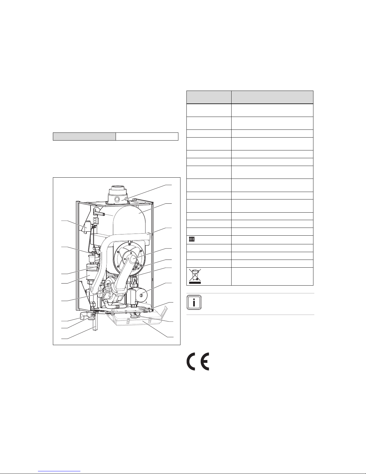
3.1 Functional elements
1
2
3
4
5
6
7
10
9
8
14
15
11
12
13
16
18
17
1 Connection for the flue
pipe
2 Integrated condensation
heat exchanger
3 Air intake pipe
4 Compact thermal mod-
ule
5 Ignition electrode
6 Water pressure sensor
7 Pump
8 Filling connection (com-
bined filling and emptying valve)
9 Connection for expan-
sion vessel
10 Electronics box
11 Condensate trap
12 Filling and drainage tap
flow
13 Connection for expan-
sion relief valve
14 Gas valve
15 Air separator
16 Volume flow sensor
17 Automatic air vent
18 Flow switch with control
lines
3.2 Information on the identification plate
The identification plate is mounted on the underside of the
product in the factory.
Information on the
identification plate
Meaning
Serial number for identification; 7th to 16th digits =
product article number
VU… Vaillant gas-fired wall-hung boiler for
heating
ecoTEC plus Product description
2H, G20 - 20 mbar
(2 kPa)
Gas group and gas connection pressure
as set at the factory
Cat. Approved gas category
Types Approved flue gas connections
PMS Permissible total overpressure in heating
mode
PMW Permissible total overpressure during hot
water generation
T
max.
Max. flow temperature
ED 92/42 Current efficiency directive fulfilled with
4* rating
230 V 50 Hz Electric connection
W Max. electrical power consumption
IP Level of protection
Heating mode
P Nominal heat output range
Q Heat input range
CE label → "CE label" section
→ "Recycling and disposal" section
Note
Make absolutely sure that the product is compatible with the gas group at the installation site.
3.3 Serial number
The serial number can be found on the identification plate.
3.4 CE label
The CE label shows that the products comply with the basic
requirements of the applicable directives as stated on the
identification plate.
The declaration of conformity can be viewed at the manufacturer's site.
Page 9
Installation 4
0020029173_04 ecoTEC plus Installation and maintenance instructions 9
4 Installation
4.1 Unpacking the product
1. Remove the product from its box.
2. Remove the protective film from all parts of the product.
4.2 Checking the scope of delivery
▶ Check that the scope of delivery is complete and intact.
4.2.1 Scope of delivery
Number
Description
1
Hanging bracket
1
Heat generator
1
Condensate drain hose
1
Expansion relief valve
1 Compression joint, gas G 1
1 Seal
1
Condensate trap's cartridge installation kit
1
Enclosed documentation
1
Bag with small parts
4.3 Transporting the product
4.3.1 General
▶ Hold the load as close as possible to your body. Do not
twist your body – instead, reposition your feet.
▶ If the unit is being lifted by two persons, ensure your
movements are coordinated during lifting.
▶ Avoid bending your upper body – do not lean forwards or
to the side.
▶ Wear appropriate cut-resistant and non-slip gloves to
protect yourself against sharp edges and maintain a safe
and secure grip.
▶ If required, get somebody to assist you in this.
4.3.2 Unloading the box from the delivery van
▶ It is recommended that two people lift the unit together.
▶ Lift the box using the straps provided.
▶ Use safe lifting techniques – keep your back straight and
bend your legs at the knee.
▶ Hold the load as close as possible to your body.
▶ If the unit is being lifted by two persons, ensure your
movements are coordinated during lifting.
▶ If required, get somebody to assist you in this.
4.3.3 Transporting the box from the delivery
point to the installation site – ground floor
▶ It is recommended that two people lift the unit together.
▶ Use safe lifting techniques – keep your back straight and
bend your legs at the knee.
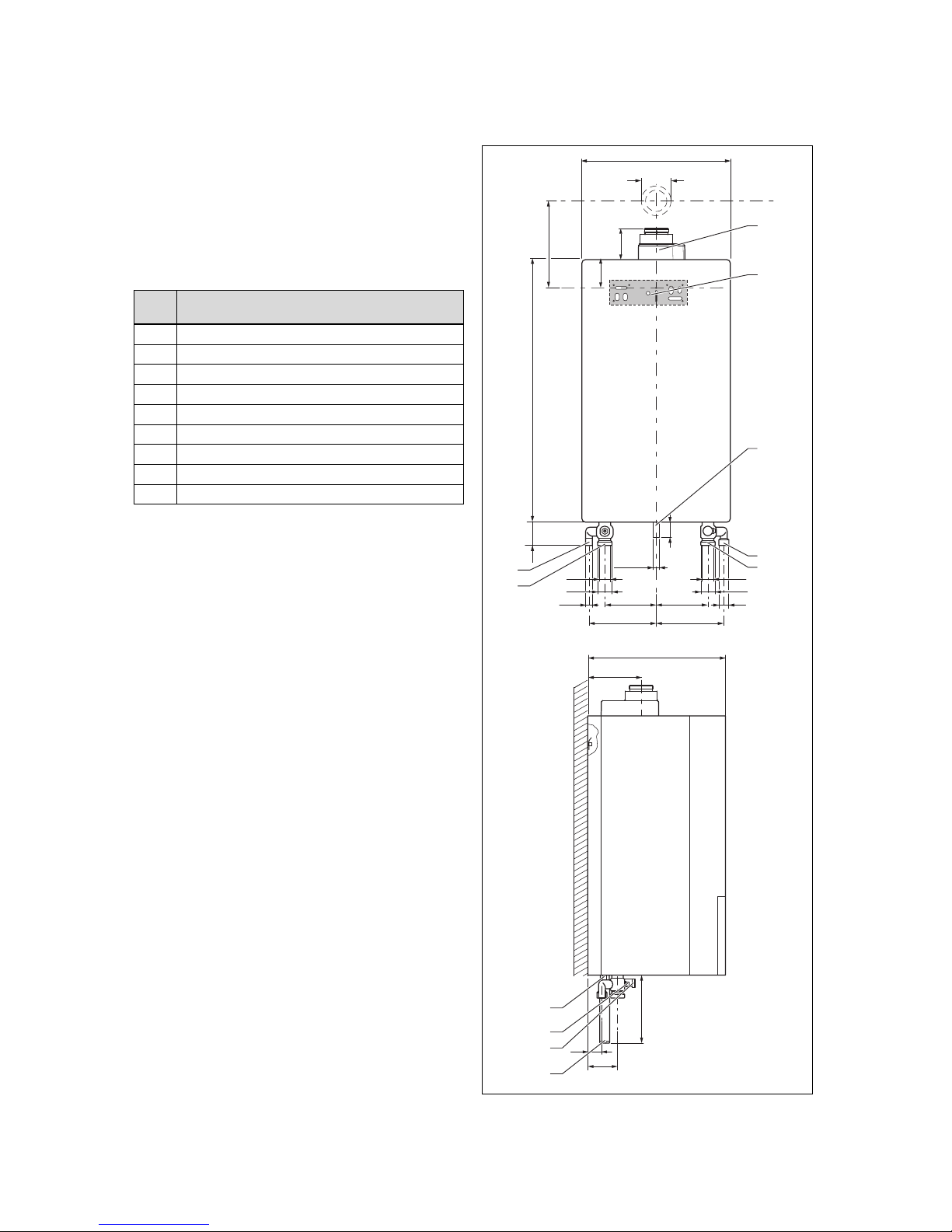
4.4 Product dimensions and connection
dimensions
A
Ø 80/125
R 1
172
172
32
224 224
121
140
75
211
800
61
94
119
Ø 25, R1
G 1 1/
2
Rp 1 Rp 1
G 1 1/
2
R 3/
4
480
472
6
7
5
4
3
9
11
10
8
1
2
Page 10
4 Installation
10 Installation and maintenance instructions ecoTEC plus 0020029173_04
1 Flue gas connection,
80/125 diameter
2 Hanging bracket
3 Gas pipe, 25 mm dia-
meter, gas connection
R1“
4 Expansion vessel con-
nection
5 Heating return connec-
tion
6 Heating flow connection
7 Expansion relief valve
connection
8 Condensate discharge
connection
9 Flow drain opening
10 Filling connection option
(combined filling and
emptying valve)
11 Condensate trap's
cartridge
Consult the installation template that is supplied to find the
dimension A.
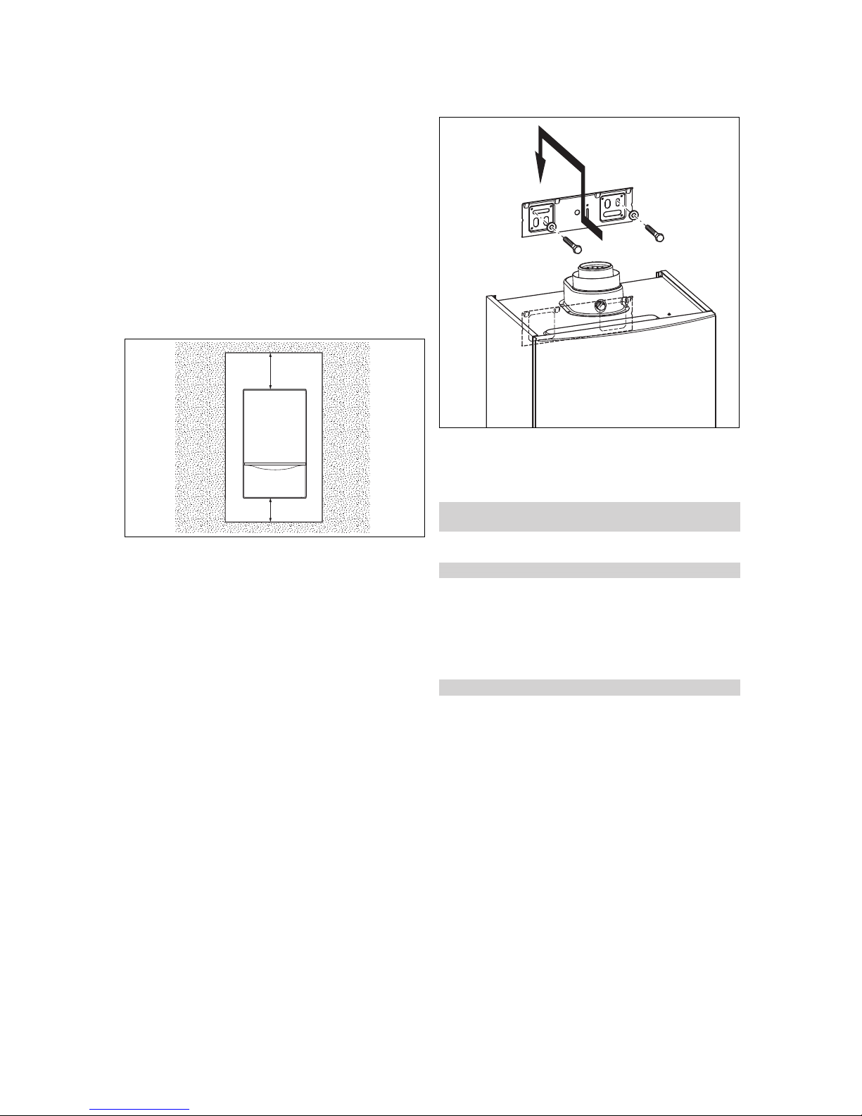
4.5 Minimum clearances and installation
clearances
AB
A 500 mm B 400 mm
▶ When using the accessories, observe the minimum clear-
ances/installation clearances.
4.6 Clearance from combustible components
It is not necessary to ensure that there is a clearance
between the product and combustible components, as the
temperature of the product will never exceed the maximum
permissible temperature of 85 °C at its nominal heat output.
4.7 Using the installation template
1. Position the installation template vertically over the in-
stallation site.
2. Secure the template to the wall.
3. Mark on the wall all the points required for the installa-
tion.
4. Remove the installation template from the wall.
5. Drill all the holes required.
6. Make any perforations necessary.
4.8 Wall-mounting the product
1. Check whether the wall has sufficient load-bearing capacity to bear the operational weight of the product.
2. Check if the supplied fixing material may be used for
the wall.
Conditions: The load-bearing capacity of the wall is sufficient; the fixing
material is permitted for the wall
▶ Wall-mount the product as described.
Conditions: The load-bearing capacity of the wall is not sufficient
▶ Ensure that wall-mounting apparatus on-site has a suf-
ficient load-bearing capacity. Use individual stands or
primary walling, for example.
▶ Do not wall-mount the product if you cannot provide
wall-mounting apparatus with a sufficient load-bearing
capacity.
Conditions: The fixing material may not be used for the wall
▶ Wall-mount the product as described using the permitted
fixing material provided on-site.
Page 11

Installation 5
0020029173_04 ecoTEC plus Installation and maintenance instructions 11
4.9 Removing or installing the front casing
4.9.1 Removing the front casing
1
2
1. Undo the bolt (1).
2. Push in both retaining clips (2) so that the front casing
is released.
3. Pull the front casing forwards at the bottom edge.
4. Lift the front casing upwards from the bracket.
4.9.2 Installing the front casing
1. Place the front casing on the upper brackets.
2. Push the front casing onto the product until both retaining clips (2) snap into place at the front casing.
3. Secure the front casing by tightening the bolt (1).
5 Installation
Danger!
Risk of explosion or scalding caused by
incorrect installation.
Stresses in the supply line can cause leaks.
▶ Make sure there is no voltage in the sup-
ply lines when they are installed.
Caution.
Risk of damage caused by contaminated
lines.
Foreign bodies, such as welding remnants,
sealing residues or dirt in the water pipes,
may cause damage to the product.
▶ Flush the heating installation thoroughly
prior to installation.
Seals made of rubber-like materials may be subject to plastic
deformation, which can lead to pressure losses. We recommend using seals made of a paste-like fibre material.
You must only start up the product if a sufficiently dimensioned low loss header has been installed between the heat
generation circuit and the heating circuit or cylinder charging
circuit.
5.1 Selecting a low loss header
The low loss header disconnects the heat generator from
the heating system. This means that the system is no longer
dependent on the heat generator's remaining feed head.
In conjunction with the heating pump, the low loss header
ensures that a sufficiently high minimum quantity of water is
always circulating through the heat generator.
Heating system output Heating system spread
10 K 15 K 20 K
Individual unit WH 160 WH 95 WH 95
Dual cascade WH 280 WH 160 WH 95
Three-unit cascade WH 280 WH 280 WH 160
For old systems in particular, we recommend installing a
heating dirt filter in the return to the low loss header (not to
the product). This protects the product against dirt from the
system. Ensure that there is sufficient dimensioning in order
to prevent it from blocking quickly and to prevent high pressure losses.
You do not need any electrical accessories when using a
low loss header. You can connect simple systems directly
inside the electronics box; see the connection diagram
(→ Page 36).
5.1.1 Heating circuit connection with low loss
header
1
2
3
4
1 Product with internal
pump
2 Low loss header
3 External heating pump
4 Consumer (e.g. heating
circuit)
The product can directly operate a heating circuit via the low
loss header.
▶ Downstream of the low loss header, select a heating
pump that is appropriate for the system.
▶ For multi-circuit systems, pay additional attention to the
control system accessories.
The settings for the internal pump are made at the factory.
▶ Connect the external heating pump to the grey ProE plug
X13.
▶ Set the diagnostics code D.26 to 2.
Page 12
5 Installation
12 Installation and maintenance instructions ecoTEC plus 0020029173_04
5.1.2 Cylinder priority switching via low loss
header
1
2
3
4
1 Product with internal
pump
2 Low loss header
3 External cylinder char-
ging pump
4 Consumer (e.g. cylinder
charging circuit)
The product's electronics are designed in such a way that
you can connect one cylinder charging circuit and one heating circuit directly without the need for accessories. The cylinder charging circuit connection downstream of the low loss
header means that you can select an individual cylinder size
and a cylinder charging pump.
▶ Note that non-return valves or mixer circuits may be re-
quired in order to eliminate cross-flow to other circuits or
the effects of high temperatures from the cylinder charging circuit.
▶ Connect the cylinder charging pump to the ProE plug X6.
To start up the cylinder charging pump, it is not necessary to
set a diagnostics code. The slot on the PCB is reserved for
the cylinder charging pump.
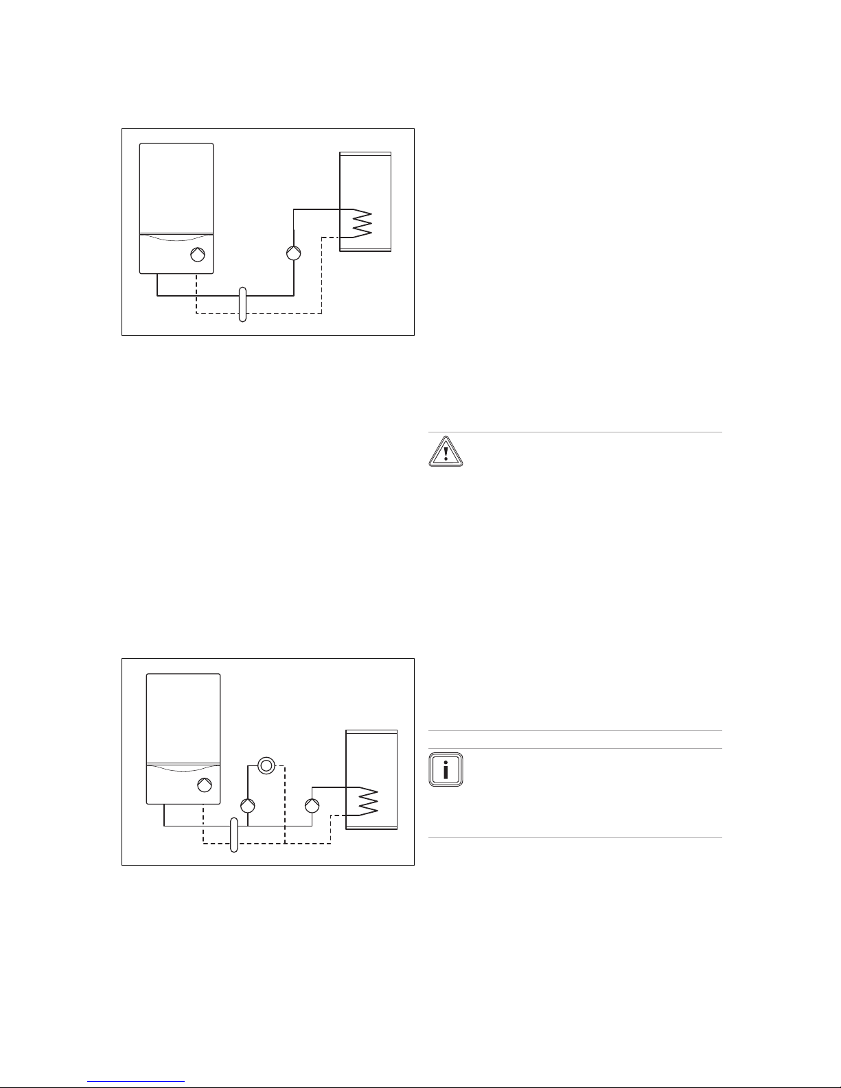
5.1.3 Cylinder priority switching and heating
circuit via low loss header
1
2
3
4
5
6
1 Product with internal
pump
2 Low loss header
3 External heating pump
4 Consumer (e.g. heating
circuit)
5 External cylinder char-
ging pump
6 Cylinder
The product's electronics are designed in such a way that
you can connect a standard system (one heating circuit and
one cylinder charging circuit) without the need for special accessories. If several circuits are required, special accessories and/or controllers are required. The product's remaining feed head for the low loss header is sufficient. You can
individually design the cylinder charging circuit connection
downstream of the low loss header (cylinder size, cylinder
charging pump size, etc.).
▶ Note that non-return valves or mixer circuits may be re-
quired in order to eliminate cross-flow to other circuits or
the effects of high temperatures from the cylinder charging circuit.
To start up the cylinder charging pump, it is not necessary to
set a diagnostics code. The slot on the PCB is reserved for
the cylinder charging pump.
The settings for the internal pump are made at the factory.
▶ Connect the cylinder charging pump to the ProE plug X6.
▶ Connect the external heating pump to the grey ProE plug
X13.
▶ Set the diagnostics code D.26 to 2.
5.2 Gas installation
5.2.1 Performing the gas installation
Caution.
Risk of material damage due to the gas
leak-tightness test.
At a test pressure of >11 kPa (110 mbar), gas
leak-tightness tests may cause damage to
the gas valve.
▶ If, during gas leak-tightness tests, you
also place the gas lines and the gas valve
in the product under pressure, use a max.
test pressure of 11 kPa (110 mbar).
▶ If you cannot limit the test pressure to
11 kPa (110 mbar), close any gas isolator
cocks that are installed upstream from the
product before you carry out the gas leaktightness test.
▶ If, during gas leak-tightness tests, you
have closed the gas isolator cock that is
installed upstream of the product, relieve
the gas line pressure before you open this
gas isolator cock.
Note
Do not reduce the gas pipe dimension downstream of the gas meter. Maintain the dimension
right up to the product. Select the correct gas isolator cock. When using an atmospheric sensing
device, select the next-highest pipe cross-section.
Page 13
Installation 5
0020029173_04 ecoTEC plus Installation and maintenance instructions 13
1
▶ Install the gas line without tension in accordance with the
recognised rules of technology.
▶ Make sure that the existing gas meter is capable of
passing the rate of gas supply required.
▶ Remove the residues from the gas line by blowing
through the gas line beforehand.
▶ Screw the gas pipe (1) to the (preinstalled) gas isolator
cock so that it is gas-tight. To do this, use the enclosed
compression joint G 1.
▶ Purge the gas line before start-up.
▶ Check the gas connection for leak-tightness.
5.3 Hydraulics installation
Caution.
Risk of material damage due to corrosion.
If non-diffusion-tight plastic pipes are used in
the heating installation, this may cause air to
enter the heating water and lead to corrosion
of the heat generation circuit and the product.
▶ If using non-diffusion-tight plastic pipes
in the heating installation, separate the
system by installing an external heat exchanger between the product and the
heating installation.
Caution.
Risk of material damage due to heat trans-
fer during soldering.
Heat that is transferred during soldering may
cause damage to the seals in the service
valves.
▶ Do not solder the connection pieces if
the connection pieces are screwed to the
service valves.
▶ If you are using plastic pipes in the heating installation,
you must install a suitable limit thermostat on-site at the
heating flow. The limit thermostat is required to protect
the heating installation against temperature-related damage if a fault occurs.
▶ Install an expansion vessel on-site in the heating return,
as close to the product as possible.
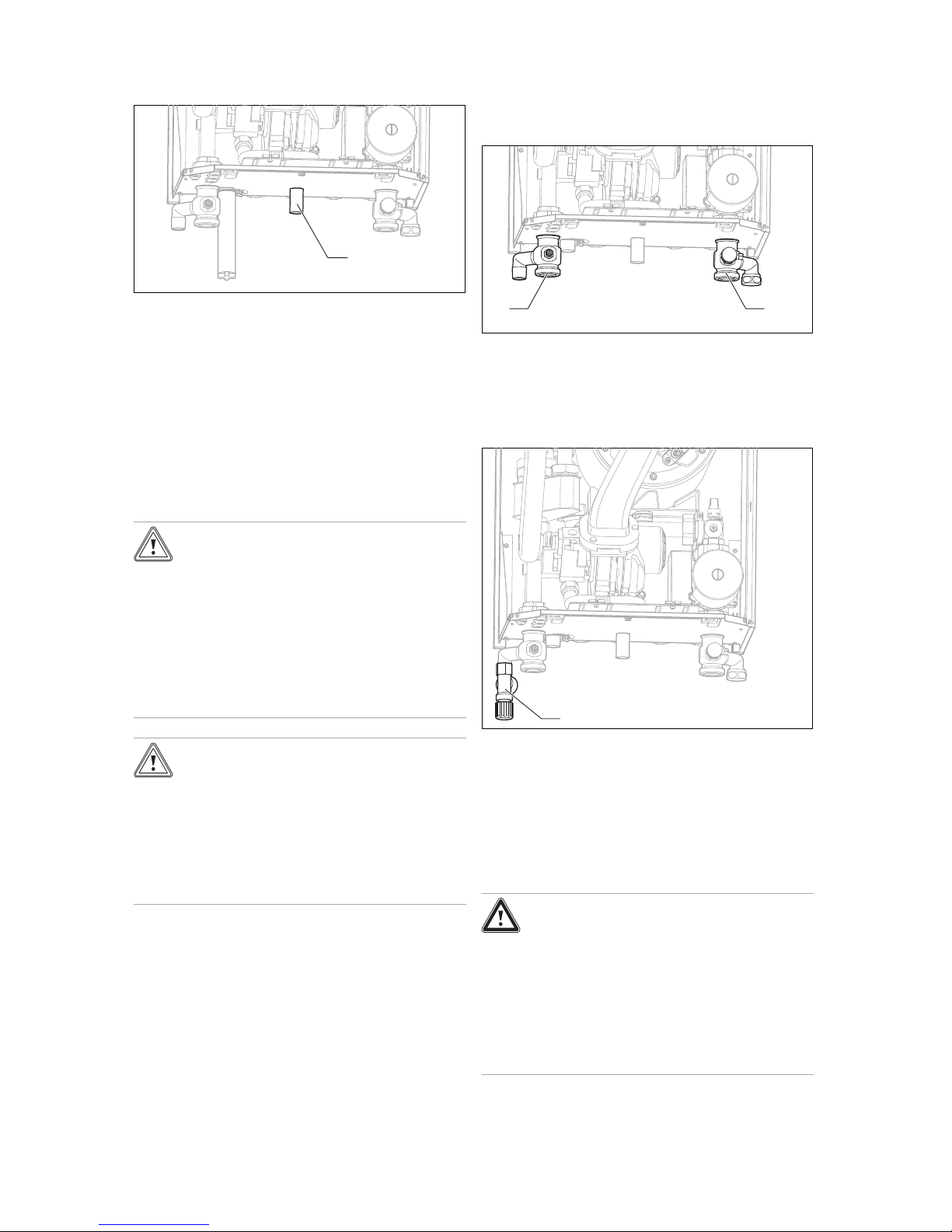
5.3.1 Connecting the heating flow and heating
return
21
1. Install service valves properly at the flow connection (1)
and the return connection (2).
2. Establish the heating connections in accordance with
the relevant standards.
5.3.2 Installing the expansion relief valve
1
1. Install the enclosed expansion relief valve.
2. Lay as short a drain line as possible for the expansion
relief valve, at a downward gradient.
3. Terminate the drain line in such a way that escaping
water or steam cannot cause injury to persons or damage to electronic components.
4. Make sure that the line end is visible.
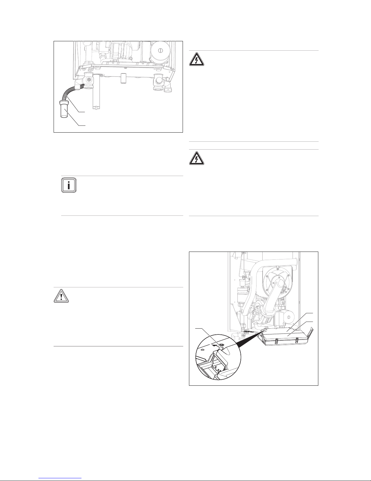
5.3.3 Connecting the condensate drain pipework
Danger!
Risk of death from escaping flue gases!
The condensate drain pipework of the condensate trap must not be connected tightly to
waste-water piping because, otherwise, the
internal condensate trap may be drained fully
and flue gas may escape.
▶ Do not connect the condensate drain
pipework tightly to the waste-water piping.
Page 14
5 Installation
14 Installation and maintenance instructions ecoTEC plus 0020029173_04
1
2
Condensate forms in the product during combustion. The
condensate drain pipework (1) routes the condensate to the
waste water connection via a tundish (2).
▶ Install the enclosed condensate drain pipework (hose)
(1).
Note
If the length of the enclosed hose is not sufficient, use only pipes that are made from
acid-resistant material (e.g. plastic) for the
condensate drain pipework and also for the
waste-water piping.
▶ Suspend the condensate drain pipework above the prein-
stalled tundish (2).
5.4 Installing and connecting the flue pipe
1. You can find out which flue pipes may be used by consulting the enclosed flue pipe installation manual.
2. Observe the information on positioning the opening
for the flue pipe. This information can be found in the
appendix.
Caution.
Risk of poisoning due to escaping flue
gas.
Mineral-oil-based greases can damage the
seals.
▶ Instead of grease, use only water or com-
mercially available soft soap to aid installation.
3. Install the flue pipe using the installation manual.
5.5 Electrical installation
Danger!
Risk of death from electric shock as a res-
ult of an improper electrical connection!
An improper electrical connection may negatively affect the operational safety of the
product and result in material damage or personal injury.
▶ Only carry out the electrical installation if
you are a trained competent person and
are qualified for this work.
▶ Observe all applicable laws, standards
and directives in the process.
▶ Earth the product.
Danger!
Risk of death from electric shock!
Touching live connections may cause serious personal injury. Since mains connection
terminals L and N also remain live even if the
boiler main switch is turned off:
▶ Switch off the power supply.
▶ Secure the power supply against being
switched on again.
5.5.1 Opening or closing the electronics box
5.5.1.1 Opening the electronics box
1. Remove the front casing. (→ Page 11)
2
1
3
2. Tilt the electronics box (3) forwards.
3. Detach the left and right clips (1) from the brackets.
4. Fold up the cover (2).
Page 15

Installation 5
0020029173_04 ecoTEC plus Installation and maintenance instructions 15
5.5.1.2 Closing the electronics box
1. Close the cover (2) by pushing it downwards onto the
electronics box (3).
2. Ensure that all of the clips (1) audibly click into the
brackets.
3. Tilt the electronics box upwards.
5.5.2 Establishing the power supply
1. Observe the relevant regulations and the enclosed connection diagram.
2. Provide one common electricity supply for the boiler
and for the corresponding controller:
– Power supply: Single-phase, 230 V, 50 Hz
– Fuse protection: ≤ 3 A
3. Connect the product using a fixed connection and a
partition with a contact opening of at least 3 mm (e.g.
fuses or power switches), see Connection diagram
(→ Page 36).
4. Use a flexible line for the mains connection line, which
is routed through the cable duct into the product.
5. Carry out the wiring. (→ Page 15)
6. Screw the ProE plug supplied to a suitable three-core
mains connection cable which complies with the relevant standards.
7. Close the electronics box. (→ Page 15)
8. Make sure that access to the mains connection is always available and is not covered or blocked.
5.5.3 Carrying out the wiring
Caution.
Risk of material damage caused by incor-
rect installation.
Mains voltage at the incorrect plug terminals
on the ProE system may destroy the electronics.
▶ Do not connect any mains voltage to the
eBUS terminals (+/-).
▶ Only connect the mains connection cable
to the terminals marked for the purpose.
1. Route the supply lines of the components to be connected through the cable duct provided on the underside of
the product on the left.
2. Use strain reliefs.
3. Shorten the supply lines as necessary.
4. Only strip the outer sheathing of flexible lines to a maximum of 30 mm to prevent short circuits if a strand accidentally comes loose.
5. Ensure the inner conductor insulation is not damaged
when stripping the outer sheathing.
6. Only strip inner conductors just enough to establish
good, sound connections.
7. To avoid short circuits resulting from loose individual
wires, fit conductor end sleeves on the stripped ends of
the conductors.
8. Screw the respective ProE plug to the supply line.
9. Check whether all conductors are sitting mechanically
securely in the terminals of the ProE plug. Remedy this
if necessary.
10. Plug the ProE plug into the associated PCB slot.
5.5.4 Installing the controller
▶ Install the controller if necessary.
5.5.5 Connecting controllers to the electronic
system
1. Carry out the wiring. (→ Page 15)
2. If you do not connect a room/timer thermostat, bridge
terminals 3 and 4, if no bridge exists.
3. If you connect a room/timer thermostat to terminals 3
and 4, remove the bridge.
4. If you connect a weather compensator or room thermo-
stat (continuous control – connection terminals 7, 8, 9),
leave the bridge inserted between terminal 3 and 4.
5. If you connect a limit thermostat (contact thermostat)
for underfloor heating systems, remove the bridge on
the blue ProE plug (contact thermostat) and connect the
limit thermostat here.
6. Close the electronics box. (→ Page 15)
7. To access pump operating mode 1 (continuously run-
ning pump) for multi-circuit controllers, set D.18 Pump
operating mode (→ Page 22) from 3 (intermittent pump)
to 1.
5.5.6 Connecting a low loss header sensor
1. Connect the low loss header sensor to the edge con-
nector X41 at terminal RF or to the controller. When doing so, observe the instructions for the controller.
2. Plug the edge connector into the PCB slot X41.
3. Activate the low loss header function at the controller.
5.5.7 Connecting a cylinder charging pump
▶ Connect an external cylinder charging pump (to be fitted
on-site) to the pink ProE plug X6.
5.5.8 Connecting additional components
You can actuate an additional component with the aid of the
auxiliary relay that is installed, and you can actuate two other
components with the multi-functional module.
The following components can be actuated:
1. Circulation pump
2. External pump
3. Cylinder charge pump
4. Extractor hood
5. External solenoid valve
6. External fault signal
7. Not active
8. eBUS remote control (not active)
9. Legionella protection pump (not active)
10. Not active.
Page 16
6 Start-up
16 Installation and maintenance instructions ecoTEC plus 0020029173_04
5.5.8.1 Using the auxiliary relay
1. Connect an additional component directly to the integrated auxiliary relay using the grey plug on the PCB.
2. Carry out the wiring. (→ Page 15)
3. To start up the connected component, select the
component via D.26, see Calling up diagnostics codes
(→ Page 22).
5.5.8.2 Using the VR 40 ("2 in 7" multi-functional
module)
1. Install the components in accordance with the respective instructions.
2. Select D.27 (→ Page 22) to actuate relay 1 on the multifunctional module.
3. Select D.28 (→ Page 22) to actuate relay 2 on the multifunctional module.
5.5.9 Actuating the circulation pump according
to requirements
Note
The product's electronics provide the opportunity
to control a domestic hot water cylinder's circulation pump as necessary (similar to an automatic
light unit for stairs). It is controlled using an external button (to be fitted on-site) that can be installed anywhere in the dwelling, e.g. in the bathroom or kitchen. When the button is pressed, the
circulation pump starts up. The pump is switched
on again after five minutes. Several buttons can
be pressed in parallel. Irrespective of the external
control of the circulation pump, the "Control by
programmable time periods" function continues to
be possible when a controller is used.
Conditions: Domestic hot water cylinder connected
▶ Carry out the wiring. (→ Page 15)
▶ Connect the supply line for an external button using ter-
minals 1 (0) and 6 (functional drawing) on the X41
edge connector, which is supplied with the controller.
▶ Plug the edge connector into the PCB slot X41.
6 Start-up
6.1 Carrying out the initial start-up
Initial start-up must be carried out by a customer service
technician or an authorised competent person using the
commissioning checklist. The commissioning checklist in the
appendix (→ Page 38) of the installation instructions must be
filled in and stored carefully along with the unit's documentation.
▶ Carry out the start-up procedure using the commissioning
checklist in the appendix.
▶ Fill in and sign the commissioning checklist.
6.2 Switching on the product
▶ Set the product's main switch to 1.
◁ The basic display appears on the display.
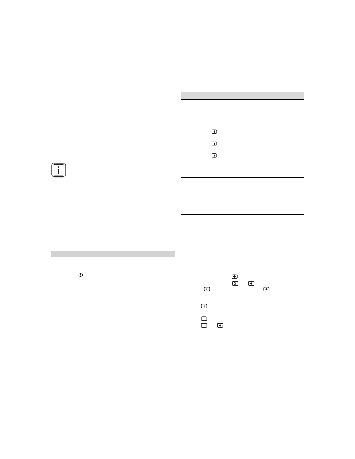
6.3 Using check programmes
By activating various check programmes, you can trigger
special functions on the product.
Display Meaning
P.0 Purging check programme:
The internal pump is cyclically actuated.
The heating circuit and the hot water circuit are
purged via the automatic air vent (the cap of the
automatic air vent must be released).
1 x : Start heating circuit purging (display view:
HP)
2 x : Start cylinder charging circuit purging
(display view: SP)
3 x : Exit purging programme
Note
The purging programme runs for 6.5 minutes per
circuit and then terminates.
P.1 Maximum load check programme:
After successful ignition, the product is operated at
maximum heat input.
P.2 Minimum load check programme:
After successful ignition, the product is operated at
minimum heat input.
P.5 SCO (safety cut-out) check programme:
The burner is switched on and the control is
switched off so that the product heats up until it
reaches the safety cut-out's switch-off temperature of
97 °C while avoiding a regular shutdown.
P.6 Check programme, diverter valve mid-position: (not
active)
You can start check programmes P.0 to P.6 by either:
– Switching on the main switch and, at the same time,
pressing and holding for five seconds or
–
Pressing and holding and at the same time, releasing and pressing and holding for five seconds
The displays shows P. 0.
▶
Press to move up the check programmes in numerical
order.
▶
Press to start the check programme.
▶
Press and at the same time to exit the check programmes. You can also exit the check programmes by
not pressing any button for 15 minutes.
Page 17
Start-up 6
0020029173_04 ecoTEC plus Installation and maintenance instructions 17
6.4 Checking and treating the heating
water/filling and supplementary water
Caution.
Risk of material damage due to poor-qual-
ity heating water
▶ Ensure that the heating water is of suffi-
cient quality.
▶ Before filling or topping up the system, check the quality
of the heating water.
Checking the quality of the heating water
▶ Remove a little water from the heating circuit.
▶ Check the appearance of the heating water.
▶ If you ascertain that it contains sedimentary materials,
you must desludge the system.
▶ Use a magnetic rod to check whether it contains mag-
netite (iron oxide).
▶ If you ascertain that it contains magnetite, clean the sys-
tem and apply suitable corrosion-protection measures, or
fit a magnet filter.
▶ Check the pH value of the removed water at 25 °C.
▶ If the value is below 8.2 or above 10.0, clean the system
and treat the heating water.
▶ Ensure that oxygen cannot get into the heating water.
(→ Page 21)
Checking the filling and supplementary water
▶ Before filling the system, measure the hardness of the
filling and supplementary water.
Treating the filling and supplementary water
▶ Observe all applicable national regulations and technical
standards when treating the filling and supplementary
water.
Provided the national regulations and technical standards
do not stipulate more stringent requirements, the following
applies:
You must treat the heating water in the following cases:
– If the entire filling and supplementary water quantity dur-
ing the operating life of the system exceeds three times
the nominal volume of the heating installation, or
– If the guideline values listed in the following table are not
met, or
– If the pH value of the heating water is less than 8.2 or
more than 10.0.
Total
heating
output
Water hardness at specific system volume
1)
≤ 20 l/kW
> 20 l/kW
≤ 50 l/kW
> 50 l/kW
kW
ppm
CaCO₃
mol/m³
ppm
CaCO₃
mol/m³
ppm
CaCO₃
mol/m³
< 50 < 300 < 3 200 2 2 0.02
> 50
to ≤ 200
200 2 150 1.5 2 0.02
> 200
to ≤ 600
150 1.5 2 0.02 2 0.02
> 600 2 0.02 2 0.02 2 0.02
1) Nominal capacity in litres/heating output; in the case of multiboiler systems, the smallest single heating output is to be used.
Caution.
Risk of material damage if the heating
water is treated with unsuitable frost or
corrosion protection agents.
Frost and corrosion protection agents may
cause changes in the seals, noises during
heating and may lead to further damage.
▶ Do not use any unsuitable frost and corro-
sion protection agents.
No incompatibility with our products has been detected to
date with proper use of the following additives.
▶ When using additives, follow the manufacturer's instruc-
tions without exception.
We accept no liability for the compatibility of any additive or
its effectiveness in the rest of the heating system.
Additives for cleaning measures (subsequent
flushing required)
– Fernox F3
– Sentinel X 300
– Sentinel X 400
Additives intended to remain permanently in the
system
– Fernox F1
– Fernox F2
– Sentinel X 100
– Sentinel X 200
Additives for frost protection intended to remain
permanently in the system
– Fernox Antifreeze Alphi 11
– Sentinel X 500
▶ If you have used the above-mentioned additives, inform
the operator about the measures required.
▶ Inform the operator about the measures required for frost
protection.
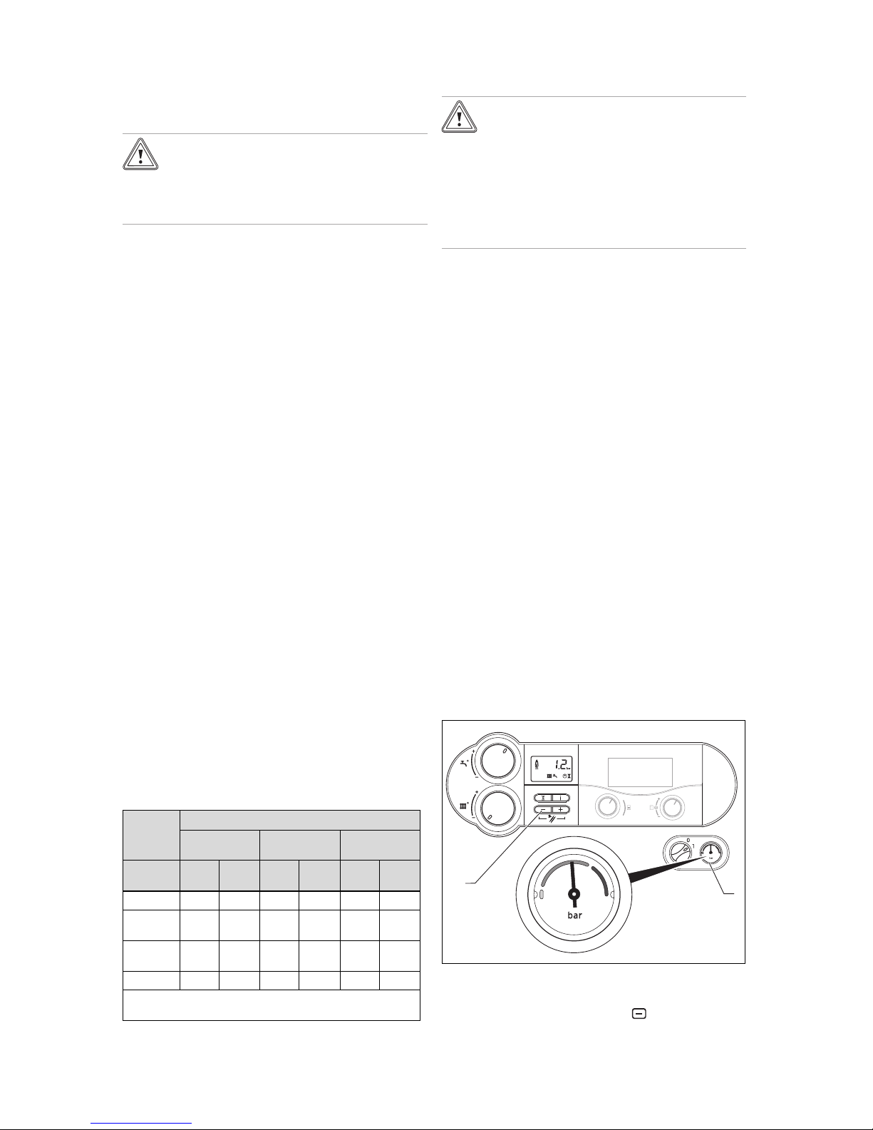
6.5 Reading off the filling pressure
1
2
The product has an analogue pressure gauge (1) and a digital pressure display.
▶
To read off the digital value, press (2).
Page 18
6 Start-up
18 Installation and maintenance instructions ecoTEC plus 0020029173_04
If the heating installation is full, the indicator on the pressure
gauge must point to the upper half of the grey area when the
heating installation is cold in order to ensure that it operates
smoothly. This corresponds to a filling pressure of between
0.1 MPa and 0.2 MPa (1.0 bar and 2.0 bar).
If the heating installation extends over several storeys,
higher filling pressures may be required to avoid air entering
the heating installation.
6.6 Preventing low water pressure
To prevent damage to the heating installation that is caused
by low filling pressure, the product is fitted with a water
pressure sensor. If the filling pressure falls below 0.06 MPa
(0.6 bar), the product indicates low pressure by displaying a
flashing pressure value. If the filling pressure falls below 0.03
MPa (0.3 bar), the product switches off. The display shows
F.22.
▶ Top up the heating water to start the product up again.
The pressure value flashes on the display until a pressure of
0.11 MPa (1.1 bar) or higher has been reached.
▶ If you notice frequent losses in pressure, determine and
eliminate the cause.
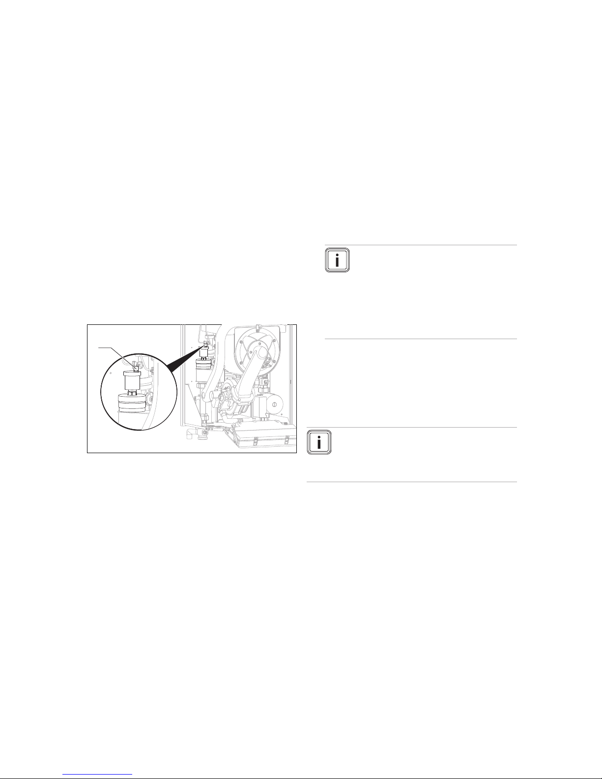
6.7 Filling and purging the heating installation
1
1. Flush the heating installation thoroughly before filling it.
2. Undo the cap of the automatic air vent (1) by one to two
rotations and leave it open, as the product purges itself
via the automatic air vent even in continuous mode.
3. Observe the explanations on the topic of Treating
(→ Page 17) heating water.
4. Connect the filling and drainage tap in the heating installation to a heating water supply in accordance with
the relevant standards.
5. Open the heating water supply.
6. Open all thermostatic radiator valves.
7. If necessary, check that both service valves on the
product are open.
8. Slowly open the filling and drainage tap so that the water flows into the heating installation.
9. Purge the lowest radiator until water flows out of the
purging valve without bubbles.
10. Purge all other radiators until the heating installation is
completely filled with water.
11. Close all purging valves.
12. Monitor the rising filling pressure in the heating installa-
tion.
13. Fill with water until the required filling pressure is
reached.
14. Close the filling and drainage tap and the heating water
supply.
15. Check all connections and the entire system for leaks.
16. To purge the heating installation, select the check programme P.0.
◁ The product does not start up, the internal pump
operates intermittently and purges either the heating
circuit or the hot water circuit. The display shows
the filling pressure of the heating installation.
17. To be able to carry out the purging process properly,
the heating installation filling pressure must not fall below the minimum filling pressure.
– Minimum heating installation filling pressure:
0.08 MPa (0.80 bar)
Note
The check programme P.0 runs for
6.5 minutes per circuit.
At the end of the filling procedure, the
filling pressure of the heating installation
should be at least 0.02 MPa (0.2 bar) above
the counter-pressure of the expansion
vessel ("Exp") (P
Installation
≥ P
Exp
+ 0.02 MPa
(0.2 bar)).
18. If there is still too much air in the heating installation at
the end of the check programme P.0, repeat the check
programme.
19. Check all connections for leaks.
6.8 Flushing the heating installation for the first
time ("cold")
Note
The complete heating system must be flushed
at least twice: Once with cold water and once
with hot water in accordance with the following
instructions.
1. Check whether all thermostatic radiator valves and both
service valves on the product are open.
2. Connect a hose to the drain valve that is located at the
lowest position in the heating system.
3. Open the radiator valves and the drain valves so that
the water can drain quickly. Start at the next point in the
system and open the purging valves on the radiators so
that the contaminated water can completely drain.
4. Close the drain cocks.
5. Refill the heating system with water.
6. Check that the expansion relief valve of the heating
system is functioning correctly by turning the handle
on the valve.
7. Check the pressure in the heating system and top up
with water if necessary.
8. Close the filling valve and the cold water valve.
Page 19
Start-up 6
0020029173_04 ecoTEC plus Installation and maintenance instructions 19
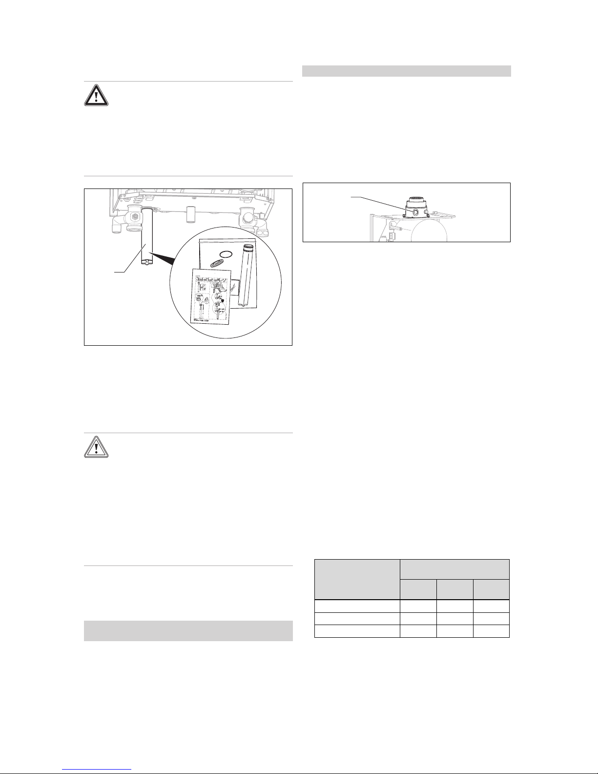
6.9 Filling the condensate trap
Danger!
Risk of poisoning due to escaping flue
gas.
An empty or insufficiently filled condensate
trap may allow flue gas to escape into the
room air.
▶ Fill the condensate trap with water before
starting up the product.
1
1. Install the condensate trap's cartridge (1) in accordance
with the enclosed installation manual.
2. Fill the condensate trap in accordance with the enclosed description.
6.10 Gas ratio setting
6.10.1 Checking the factory setting
Caution.
An incorrect gas group setting may cause
operating faults or a reduction in the
working life of the product.
If the product design does not match the local
gas group, malfunctions will occur or you will
have to replace product components prematurely.
▶ Before you start up the product, compare
the gas group information on the identification plate with the gas group available at
the installation site.
The product's combustion has been factory tested and is
preset for operation with the gas group indicated on the identification plate. In some supply areas, these settings may
need to be adjusted at the installation site.
Conditions: The product design is not compatible with the local gas
group
▶ Do not start up the product.
Conditions: The product design is compatible with the local gas group
▶ Proceed as described below.
6.10.2 Checking the leak-tightness of the flue gas
system and for flue gas recirculation
1. Check that the flue gas system is intact, in accordance
with British Gas TB 200.
2. If the flue gas system is longer than 2 m, we urgently
recommend that you test the system for flue gas recirculation as described below.
1
3. Use the air analysis point (1) to check for flue gas recir-
culation.
4. Use the flue gas measuring instrument.
5. If you discover CO or CO2 in the fresh air, search for a
leak in the flue gas system or for the flue gas recirculation.
6. Eliminate the damage.
7. Repeat the above-mentioned test to determine if the
fresh air contains CO or CO2.
8. If you cannot eliminate the damage, you must not start
up the boiler.
6.10.3 Checking the gas flow rate
The boiler is fitted with a multifunctional automatic gas valve
which ensures that the precise air/gas ratio is provided under all operating conditions. The gas flow rate has been set
during production and does not require adjustment. With the
front casing fitted check the gas flow rate of the boiler as follows:
▶ Start up the product with the check programme P.01.
▶ In addition, ensure that maximum heat can be dissipated
into the heating system by turning up the room thermostat.
▶ Wait at least 5 minutes until the boiler has reached its
operating temperature.
▶ Ensure that all other gas appliances in the property are
turned off.
▶ Measure the gas flow rate at the gas meter.
▶ Compare the measured values with the corresponding
values in the table.
Nominal value for the
net heat supply in kW
in accordance with
BS EN 483
H gas in m³/h
Nominal +5% −10%
76.2 8.10 8.51 7.29
95.2 10.10 10.61 9.09
114.3 12.10 12.71 10.89
Page 20
6 Start-up
20 Installation and maintenance instructions ecoTEC plus 0020029173_04
Conditions: Gas flow rate not in the permissible range
▶ Check all of the piping and ensure that the gas flow rates
are correct.
▶ Only put the product into operation once the gas flow
rates have been corrected.
Conditions: Gas flow rate in the permissible range
▶ End the check programme P.01.
▶ Allow the boiler to cool down by allowing pump overrun to
operate for a minimum of two minutes.
▶ Record the boiler maximum gas flow rate onto the
Benchmark gas boiler commissioning checklist.
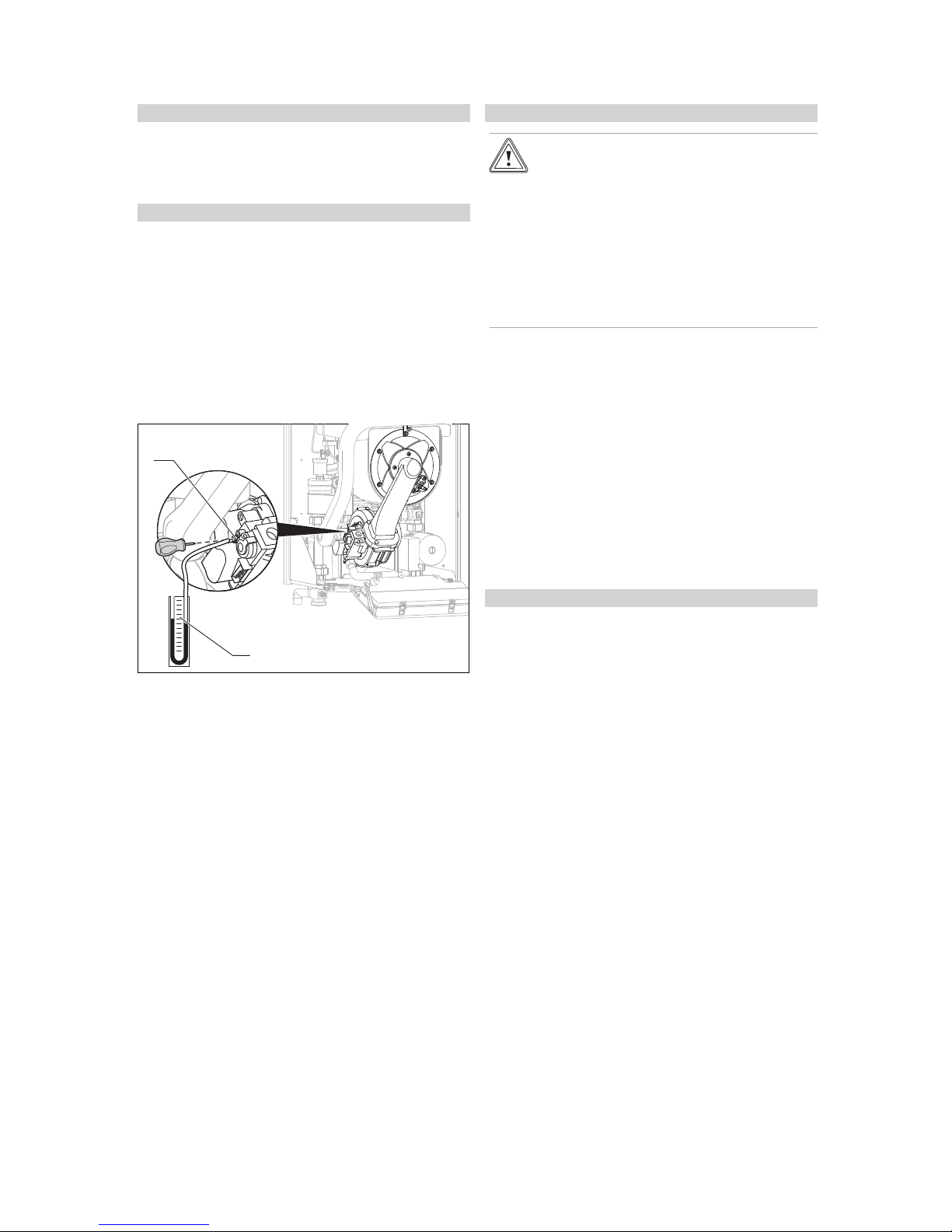
6.10.4 Checking the gas flow pressure
1. Ensure that the gas inlet working pressure can be
obtained with all other gas appliances in the property
working.
2. Close the gas isolator cock.
1
2
3. Undo the sealing screw (1) that is marked with in on the
gas valve.
4. Connect a digital pressure gauge or U-tube manometer
(2).
5. Open the gas isolator cock.
6. Start up the product with the check programme P.1.
7. In addition, ensure that maximum heat can be dissipated into the heating system by turning up the room
thermostat.
8. With the boiler operating at full load check that the gas
inlet working pressure at the reference test point (1)
complies with the requirements.
– Permissible gas flow pressure for operation with
G20 natural gas: 1.6 … 2.3 kPa (16.0 … 23.0 mbar)
9. Should the pressure recorded at the reference test point
in the boiler be lower than indicated check if there is
any blockage in the pipework or if the pipework is undersized.
Conditions: Gas flow pressure not in the permissible range
Caution.
Risk of material damage and operating
faults caused by incorrect gas flow pressure.
If the gas flow pressure lies outside the permissible range, this can cause operating
faults in and damage to the product.
▶ Do not make any adjustments to the
product.
▶ Check the gas installation.
▶ Do not start up the product.
▶ If you cannot correct the failure, notify the gas supply
company and proceed as follows:
▶ End the check programme P.01.
▶ Allow the boiler to cool down by allowing pump overrun
to operate for a minimum of two minutes.
▶ Close the gas isolator cock.
▶ Remove the pressure gauge and retighten the sealing
screw (1) for the measuring nipple.
▶ Open the gas isolator cock.
▶ Check the measuring nipple for gas tightness.
▶ Close the gas isolator cock.
▶ Install the front casing. (→ Page 11)
▶ Disconnect the product from the power mains.
▶ You must not start up the boiler.
Conditions: Gas flow pressure in the permissible range
▶ End the check programme P.01.
▶ Allow the boiler to cool down allowing pump overrun to
operate for a minimum of two minutes.
▶ Close the gas isolator cock.
▶ Remove the pressure gauge and retighten the sealing
screw (1) for the measuring nipple.
▶ Open the gas isolator cock.
▶ Check the measuring nipple for gas tightness.
▶ Install the front casing. (→ Page 11)
▶ Reset boiler controls for normal operation.
▶ Record the appliance gas inlet working pressure (kPa
resp. mbar) in the Benchmark gas boiler commissioning
checklist.
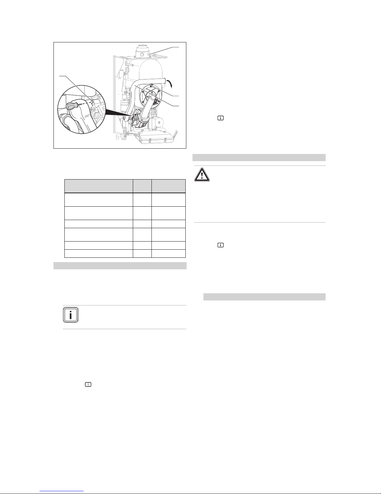
6.10.5 Checking the CO₂ content and, if
necessary, adjusting it (air index setting)
1. Start up the product with the check programme P.1.
2. Wait at least five minutes until the product reaches its
operating temperature.
Page 21
Start-up 6
0020029173_04 ecoTEC plus Installation and maintenance instructions 21
1
2
3
4
3. Measure the CO₂ and CO/CO₂ content at the flue gas
analysis point (1).
4. Compare the measured value with the corresponding
value in the table.
Settings Unit G20 natural
gas
CO₂ after 5 minutes in full load
mode with front casing closed
Vol.–% 9.2 ± 1.0
CO₂ after 5 minutes in full load
mode with front casing removed
Vol.–% 9.0 ± 1.0
Set for Wobbe index W₀ kWh/m³ 14.1
O₂ after 5 minutes in full load
mode with front casing closed
Vol.–% 4.53 ± 1.8
CO value with full load
ppm ≤ 250
CO/CO₂
≤ 0.0031
Conditions: The CO₂ content must be adjusted
▶ Unscrew the screw (2) and tilt the air intake pipe (3) for-
wards by 90°. Do not remove the air intake pipe.
▶ Set the CO₂ content (value with front casing removed)
by turning the screw (4).
Note
Turn to the left: Higher CO₂ content
Turn to the right: Lower CO₂ content
▶ Only carry out the adjustment in increments of 1/8 turn
and wait approximately 1 minute after each adjustment
until the value stabilises.
▶ After performing the adjustments, tilt the air intake pipe
back up.
▶ Check the CO₂ content again.
▶ If necessary, repeat the setting process.
▶
Press the button. Full load mode is also exited if no
buttons are pressed for 15 minutes.
▶ Use the screw (2) to secure the air intake pipe again.
▶ If an adjustment is not possible in the specified adjust-
ment range, you must not start up the product.
▶ If this is the case, inform Vaillant Customer Service.
▶ Install the front casing. (→ Page 11)
6.11 Checking function and leak-tightness
Before you hand the product over to the operator:
▶ Check the gas line, the flue gas installation, the heating
installation and the hot water pipes for leaks.
▶ Check that the air/flue pipe and condensate drain pipe-
work have been installed correctly.
▶ Check that the front casing has been installed correctly.
6.11.1 Checking the heating mode
1. Make sure that there is a heat requirement.
2.
Press to activate the status display.
◁ If the product is working correctly, the display shows
S.4.
6.11.2 Checking the hot water generation
Conditions: Cylinder connected
Danger!
Risk of death from Legionella.
Legionella multiply at temperatures below
60 °C.
▶ Ensure that the operator is familiar with
all of the Anti-legionella measures in order to comply with the applicable regulations regarding legionella prevention.
▶ Make sure that the cylinder thermostat is requesting
heat.
1.
Press to activate the status display.
◁ If the cylinder is charged correctly, the display
shows S.24.
2. If you have connected a controller which can be used to
set the hot water temperature, set the hot water temperature on the boiler to the maximum possible temperature.
Conditions: Water hardness: > 3.57 mol/m³, Boiler with cylinder
– Water temperature: ≤ 50 ℃
3. Adjust the target temperature for the connected domestic hot water cylinder to the controller.
◁ The boiler adopts the set target temperature which
is set on the controller (automatic calibration in
newer controllers).
6.12 Thoroughly flushing the heating installation
("hot")
1. Operate the appliance until the boiler and the heating
system are up to temperature.
2. Check the heating system for leaks.
3. Connect a hose to the drain valve located at the lowest
position of the heating system.
4. Shut off the boiler, open the drain valve and all purge
valves on the radiators and allow the water to flow out
of the heating system and the boiler quickly and fully.
5. Close the drain valve.
6. Fill the heating system again with water as described in "Filling and purging the heating installation"
(→ Page 18).
Page 22
7 Adapting the unit to the heating installation
22 Installation and maintenance instructions ecoTEC plus 0020029173_04
7. Re-fill the system until the system design pressure of
0,1 MPa (1,0 bar) is attained.
Note
The actual reading on the digital pressure
gauge should ideally be 0,05 MPa (0,5 bar)
plus an additional pressure corresponding
to the highest point of the system above the
base of the boiler – 10 m head equals an additional 1 bar reading on the pressure gauge.
The minimum pressure should not be less
than 0,1 MPa (1 bar) in any installation. If
the system is to be treated with an inhibitor it
should be applied at this stage in accordance
with the manufacturer’s instructions. Further
information can be obtained from Sentinel,
Betz Dearborn Ltd., Tel: 0151 420 9595, or
Fernox, Alpha– Fry technologies. Tel: 0870
8700362.
8. Install the front casing. (→ Page 11)
7 Adapting the unit to the heating
installation
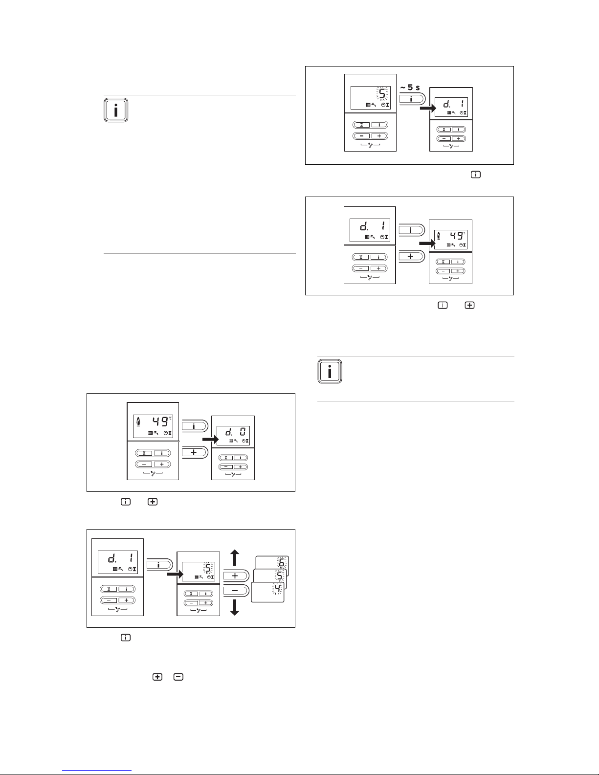
7.1 Calling up diagnostics codes
You can use the parameters that are marked as adjustable
in the overview of diagnostics codes to adapt the product to
the heating installation and the needs of the customer.
Overview of diagnostics codes (→ Page 30)
+
▶
Press and below the display at the same time.
◁ The display shows D.0 (heating partial load).
▶
Press .
◁ The display shows the associated diagnostics inform-
ation.
▶
If required, use or to change the value (the display
flashes).
▶
Save the new value by pressing and holding for approx. five seconds until the display no longer flashes.
+
▶
Exit Diagnostics mode by pressing and at the
same time or by not pressing any button for four minutes.
◁ The current heating flow temperature appears in the
display.
Note
If you activate the installer level (second diagnostics level), all of the diagnostics codes are
visible and accessible.
7.2 Calling up the installer level (second
diagnostics level)
▶ In the first diagnostics level, scroll to D.97.
▶ Change the displayed value to 17 (password).
▶ Save the setting.
7.3 Setting the heating partial load
The product's heating partial load is set to 46 kW at the factory. You can specify a value that corresponds to the product
output in kW under diagnostics code D. 0.
7.4 Setting the pump overrun and pump
operating mode
You can set the pump overrun under D.1 (default setting: 5
min.).
You can set the overrun behaviour of the pump to a different
mode under D.18.
Overrun: After ending the heating demand, the pump overruns the time that is set under D.1.
Continuous: The pump is switched on if the rotary knob for
setting the heating flow temperature is not at the left-hand
stop and the heat requirement is enabled by an external controller.
Intermittent: This pump operating mode is useful for removing residual heat after charging when the heat demand is extremely low and large temperature differences exist between
Page 23
Adapting the unit to the heating installation 7
0020029173_04 ecoTEC plus Installation and maintenance instructions 23
the cylinder charging and heating mode target values. This
prevents the living rooms from overheating. If there is a heat
demand, the pump is switched on every 25 minutes for 5
minutes once the overrun time has elapsed.
7.5 Setting the maximum flow temperature
You can set the maximum flow temperature for the heating
mode under D.71 (default setting: 75 °C).
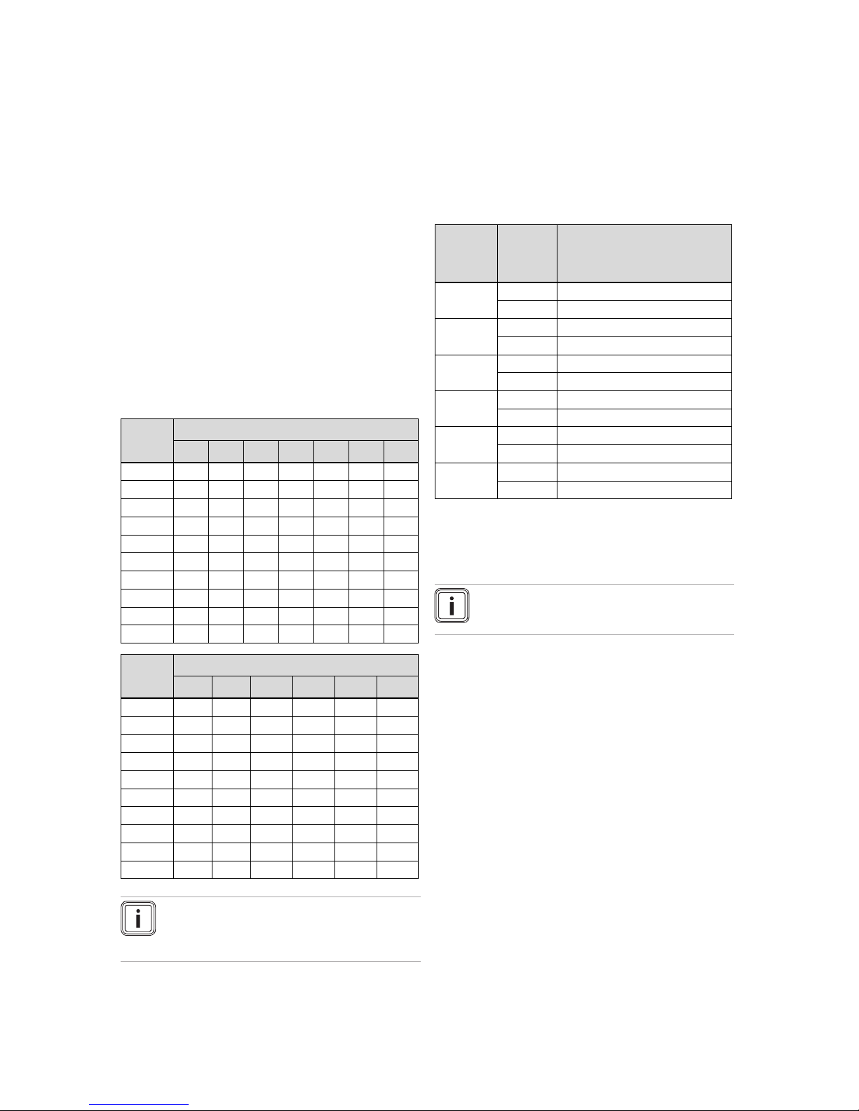
7.6 Setting the burner anti-cycling time
To prevent frequent switching on and off of the burner and
thus prevent energy losses, an electronic restart lockout
is activated for a specific period each time the burner is
switched off. You can adjust the burner anti-cycling time to
the conditions of the heating installation. The burner anticycling time is only active for the heating mode. Hot water
handling mode during a burner anti-cycling time does not
affect the time function element. You can set the maximum
burner anti-cycling time under D.2 (default setting: 20 min.).
The effective burner anti-cycling times with respect to the
target flow temperature and the maximum set burner anticycling time can be found in the following table:
T
Flow
(target)
[°C]
Set maximum burner anti-cycling time [min]
1 5 10 15 20 25 30
30 2.0 4.0 8.5 12.5 16.5 20.5 25.0
35 2.0 4.0 7.5 11.0 15.0 18.5 22.0
40 2.0 3.5 6.5 10.0 13.0 16.5 19.5
45 2.0 3.0 6.0 8.5 11.5 14.0 17.0
50 2.0 3.0 5.0 7.5 9.5 12.0 14.0
55 2.0 2.5 4.5 6.0 8.0 10.0 11.5
60 2.0 2.0 3.5 5.0 6.0 7.5 9.0
65 2.0 1.5 2.5 3.5 4.5 5.5 6.5
70 2.0 1.5 2.0 2.5 2.5 3.0 3.5
75 2.0 1.0 1.0 1.0 1.0 1.0 1.0
T
Flow
(target)
[°C]
Set maximum burner anti-cycling time [min]
35 40 45 50 55 60
30 29.0 33.0 37.0 41.0 45.0 49.5
35 25.5 29.5 33.0 36.5 40.5 44.0
40 22.5 26.0 29.0 32.0 35.5 38.5
45 19.5 22.5 25.0 27.5 30.5 33.0
50 16.5 18.5 21.0 23.5 25.5 28.0
55 13.5 15.0 17.0 19.0 20.5 22.5
60 10.5 11.5 13.0 14.5 15.5 17.0
65 7.0 8.0 9.0 10.0 11.0 11.5
70 4.0 4.5 5.0 5.5 6.0 6.5
75 1.0 1.0 1.0 1.0 1.0 1.0
Note
The remaining burner anti-cycling time following a
regular shutdown in heating mode can be called
up under D.67.
7.7 Setting the maintenance interval
If you set the maintenance interval, the maintenance message SEr appears in the display after a configurable number
of burner operating hours. The display on the eBUS controller shows the information Maintenance.
▶ Use D.84 to set the operating hours until the next main-
tenance work is due. Guideline values can be found in
the following table.
Heat demand
Number
of persons
Burner operating hours until the
next inspection/maintenance work
is due (dependent upon the system type)
5.0 kW
1 ‑ 2 1050 h
2 ‑ 3 1150 h
10.0 kW
1 ‑ 2 1500 h
2 ‑ 3 1600 h
15.0 kW
2 ‑ 3 1800 h
3 ‑ 4 1900 h
20.0 kW
3 ‑ 4 2600 h
4 ‑ 5 2700 h
25.0 kW
3 ‑ 4 2800 h
4 ‑ 6 2900 h
> 27.0 kW
3 ‑ 4 3000 h
4 ‑ 6 3000 h
The values stated correspond to an average operating time
of one year.
If you do not set a numerical value but do set the symbol "–",
the Maintenance display function is not active.
Note
On completion of the set operating hours, you
must set the maintenance interval again.
7.8 Adjusting the product to large flue gas pipe
lengths
At flue gas pipe lengths greater than 10 m (system 80/125),
you can increase the product's fan speed.
▶ Increase the value by 20 under D.51.
◁ The maximum speed of the fan is increased by
200 rpm.
7.9 Handing the product over to the operator
1. When you have finished the installation, attach the
sticker supplied (835593) to the front of the product in
the operator's language.
2. Explain to the operator how the safety devices work and
where they are located.
3. Inform the operator how to handle the product. Answer
any questions the operator may have. In particular,
draw attention to the safety information which the operator must follow.
4. Inform the operator of the necessity to have the product
maintained according to the specified intervals.
5. Pass all of the instructions and documentation for the
product to the operator for safe-keeping.
Page 24

8 Inspection and maintenance
24 Installation and maintenance instructions ecoTEC plus 0020029173_04
6. Inform the operator about measures taken to ensure the
supply of combustion air and flue gas guiding, and instruct the operator that he must not make any changes.
8 Inspection and maintenance
▶ Carry out all inspection and maintenance work in the
order shown in the table "Overview of inspection and
maintenance work".
8.1 Observing inspection and maintenance
intervals
Warning.
Risk of injury and a risk of material dam-
age caused by negligent inspection and
maintenance work.
Negligence in inspection and maintenance
work, as well as failure to comply with the
specified inspection and maintenance intervals, may impair the operational safety of
the product and lead to injuries and material
damage.
▶ Instruct the operator that the prescribed
inspection and maintenance intervals
must be complied with as a minimum requirement.
▶ Carry out a regular inspection once a
year.
▶ Carry out regular maintenance work in line
with the findings from the inspection. The
maintenance interval must not be longer
than two years.
Warning.
Risk of injury and death due to improper
inspection and maintenance!
Improper performance of inspections and
maintenance work may result in leaks or
even an explosion.
▶ Inspection and maintenance work on the
product must only be carried out by professionally qualified persons.
Any customer service work must be carried out by a professionally qualified person in accordance with the safety, installation and operating provisions for gas-fired units. Professional qualification must be confirmed by an adequately
recognised organisation or public office.
Note
The person who carries out a combustion measurement must be trained in the use of a flue gas
measuring instrument and in interpreting the results. The flue gas measuring instrument that is
used must be calibrated in accordance with the
specifications of the measuring instrument manufacturer. The correct fuel type must be set on the
flue gas measuring instrument.
Proper, regular inspection and maintenance, and the exclusive use of original spare parts are absolutely essential
to ensure fault-free operation and a long working life for the
product.
Inspection
The inspection is intended to determine the actual condition
of the product and compare it with the target condition. This
is done by measuring, checking and observing.
Maintenance
Maintenance is required in order to eliminate any deviations
of the actual condition from the target condition. This usually
involves cleaning, adjusting and, if required, replacing individual components that are prone to wear (e.g. the burner
flange seal (article number 180904), the burner insulation on
the burner flange (article number 180913) and the burner insulation on the back wall of the heat exchanger (article number 0020093190)).
8.2 Procuring spare parts
The original components of the product were also certified
as part of the declaration of conformity. If you do not use certified Vaillant original spare parts for maintenance or repair
work, this voids the conformity of the product. We therefore
strongly recommend that you fit Vaillant genuine spare parts.
Information about available Vaillant original spare parts is
available by contacting the contact address provided on the
reverse of this document.
▶ If you require spare parts for maintenance or repair work,
use only Vaillant genuine spare parts.
8.3 Removing the compact thermal module
Danger!
Risk of death and risk of material damage
caused by hot flue gas.
The seal, burner insulation and self-locking
nuts on the burner flange must not be damaged. Otherwise, hot flue gases may escape
and cause personal injury and material damage.
▶ Replace the seal each time you open the
burner flange.
▶ Replace the self-locking nuts on the
burner flange each time you open the
burner flange.
▶ If the burner insulation on the heat ex-
changer's burner flange shows signs of
damage, replace the burner insulation.
▶ Replace the burner insulation on the back
wall after each time the burner flange is
opened.
Note
The compact thermal module consists of four
main components:
– Speed-regulated fan,
– Gas-air mixture fitting,
– Gas supply (mixture pipe) to the premix burner,
– Premix burner.
Page 25
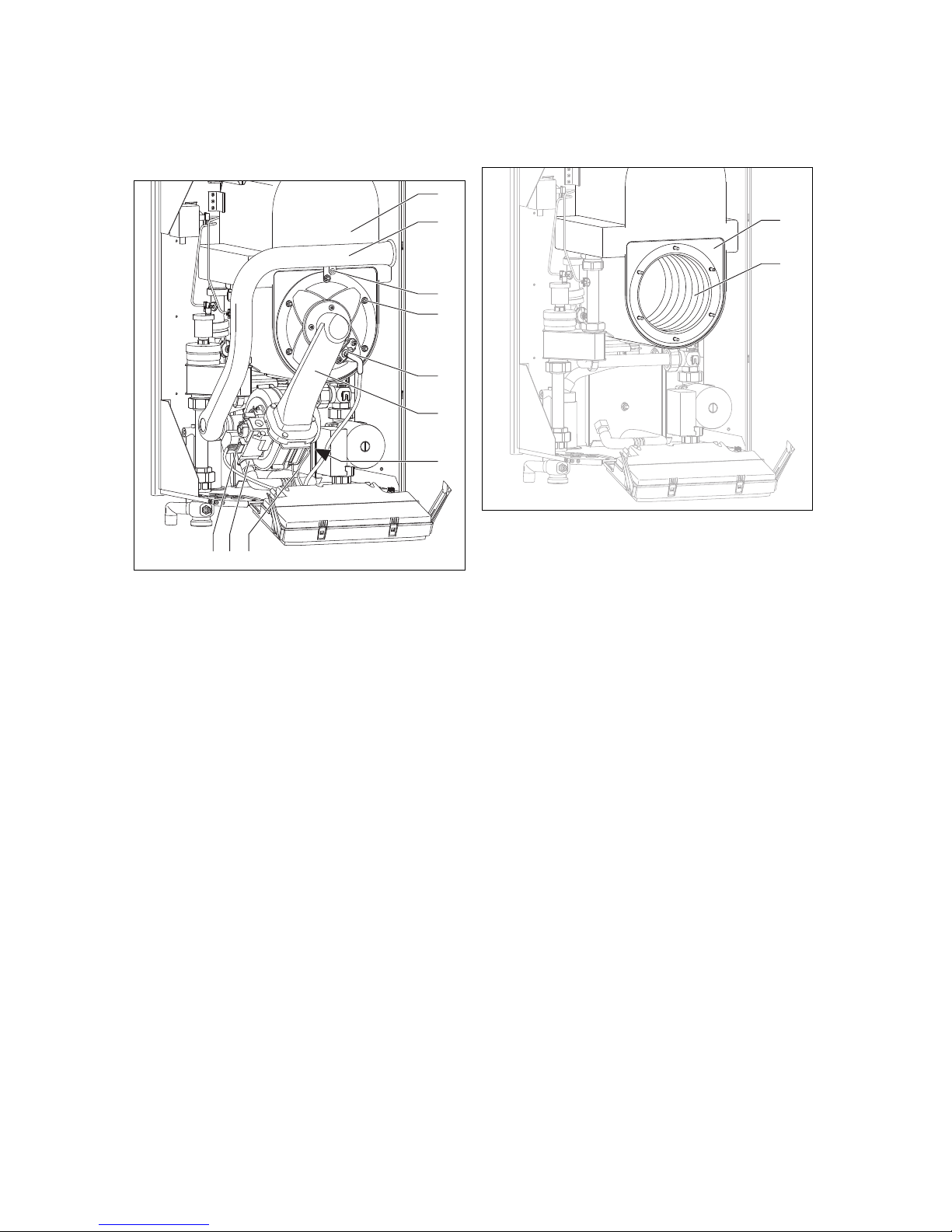
Inspection and maintenance 8
0020029173_04 ecoTEC plus Installation and maintenance instructions 25
1. Use the main switch to switch off the product.
2. Close the gas isolator cock.
3. Remove the front casing. (→ Page 11)
4. Tilt the electronics box forward.
1
2
3
4
5
6
7
8910
5. Unscrew the retaining screw (3).
6. Tilt the air intake pipe (2) forwards.
7. Remove the air intake pipe from the intake manifold.
8. Remove the ignition line and ground connection plugs
from the ignition electrode (5).
9. Disconnect the gas line (9) from the underside of the
gas valve.
10. Pull out the cable (7) from the connection plug in the
supply line to the fan motor, the PWM signal cable on
the underside of the fan (8) and the cable to the gas
valve (10).
11. Unscrew the six nuts (4).
12. Remove the entire compact thermal module (6) from
the heat exchanger (1).
13. Check the burner and the heat exchanger for damage
and dirt.
14. If necessary, clean or replace the components accord-
ing to the following sections.
15. Replace the burner insulation on the back wall of the
heat exchanger.
16. Check the burner insulation on the burner flange. If
you notice any signs of damage, replace the burner
insulation.
8.4 Cleaning the heat exchanger
1. Protect the folded down electronics box against sprayed
water.
1
2
2. Use vinegar (max. 5% acid) to clean the heating coils
(2) on the heat exchanger (1).
3. After a reaction time of 20 minutes, use a sharp jet of
water or a plastic brush to rinse the loosened dirt. Do
not point the water jet directly at the burner insulation
on the back of the heat exchanger.
◁ The water flows out of the heat exchanger through
the condensate trap.
8.5 Descaling the heat exchanger
1. Drain the product. (→ Page 27)
2. Remove the automatic air vent from the air separator.
3. Fill the product with descaler (ET 990098) via the open
connection on the automatic air vent.
4. Fill the product with clean water up to the nominal pressure.
5. Set the pump to "Continuous".
6. Use the chimney sweep button to heat up the product.
7. Leave the descaler to work in maximum output operation for approx. 30 minutes.
8. Then thoroughly rinse out the product with clean water.
9. Set the pump back to its starting condition.
10. Open the service valves and, if required, fill the heating
installation.
Page 26

8 Inspection and maintenance
26 Installation and maintenance instructions ecoTEC plus 0020029173_04
8.6 Checking the burner
1
2
3
1 2
1. Check the surface of the burner for damage. If you see
any damage, replace the burner.
2. Replace the silicone seal (1) and the silicate cord (2).
3. Check the burner insulation (3) on the burner flange
and, if required, replace the burner insulation.
8.7 Cleaning the condensate duct
2
1
1. Observe the installation manual for the condensate
trap's cartridge.
2. Remove the condensate trap's cartridge from below the
product.
3. Pull out the clamp from below the heat exchanger.
4. Remove the elbow connector.
5. Remove the condensate trap (2) and the corrugated
pipe (1). In doing so, note the position of the latching
lugs.
6. Clean the condensate trap, the corrugated pipe and the
condensate trap's cartridge.
7. Fill the condensate trap's cartridge with water.
8. Install the components with new seals and six new, selflocking nuts.
– Tightening torque: 6 Nm
8.8 Cleaning the air separation system
8.8.1 Cleaning or replacing the filter in the air
separator
1
2
3
1. Unscrew the brass cover (1) on the steel casing (3).
2. Pull the filter (2) up and out.
3. Use hot water to clean the filter, or replace the filter.
4. Insert the filter into the air separator.
5. Screw in the brass cover tightly.
8.8.2 Cleaning the air separator
1
4
2
3
1. Unscrew the nut (4).
2. Unscrew the cap nut (1).
3. Remove the cable harness.
4. Slide the casing (3) forwards and pull the entire air sep-
arator forwards and out.
5. If required, remove the pipe (2).
6. Remove the filter.
7. Use hot water to clean the air separator and the filter.
8. Replace all of the O-rings.
9. Reinstall the air separator.
Page 27

Troubleshooting 9
0020029173_04 ecoTEC plus Installation and maintenance instructions 27
8.9 Installing the compact thermal module
1
2
3
4
5
6
7
8910
1. Connect the compact thermal module (6) to the heat
exchanger (1).
2. Tighten the six nuts (4), including the retainer for the
air intake pipe, in a cross-wise pattern until the burner
flange fits closely and uniformly onto the mating surfaces.
3. Check that the blue sealing ring in the air intake pipe is
positioned correctly in the seal seat.
4. Place the air intake pipe (2) on the intake manifold, and
tighten the screw (3).
5. Connect the ignition line and the ground connection to
the ignition electrode (5).
6. Connect the cable (7) from the connection plug in the
supply line to the fan motor, the PWM signal cable to
the underside of the fan (8) and the cable to the gas
valve (10).
7. Connect the gas line (9) using a new seal. In the process, secure the gas pipe against twisting.
8. Open the gas isolator cock.
9. Make sure that there are no leaks.
8.10 Draining the product
1. Close the service valves of the product.
2. Open the drain valves on the service valves.
3. Ensure that the automatic air vent cap on the air separator is open so that the product can be drained fully.
8.11 Checking the pre-charge pressure of the
external expansion vessel
1. Depressurise the heating installation.
2. Measure the pre-charge pressure of the expansion ves-
sel at the vessel valve.
3. Fill the expansion vessel with air at a pre-charge pres-
sure of less than 0.075 (0.75 bar) according to the static
head of the heating installation.
4. If water escapes from the valve of the expansion ves-
sel, you must replace the expansion vessel.
8.12 Completing inspection and maintenance
work
▶ If required, reset the maintenance interval (→ Page 23).
▶ Check that the product works correctly and is leak-tight,
see "Checking function and leak-tightness" (→ Page 21).
9 Troubleshooting
You can find an overview of the fault codes in the appendix.
Overview of fault codes (→ Page 34)
9.1 Contacting your service partner
If you contact your service partner, if possible, please mention
– the fault code that is displayed (F.xx),
– the product status (S.xx) that is displayed.
9.2 Calling up status codes
You can find an overview of the status codes in the
appendix.
Status codes – Overview (→ Page 33)
▶
To call up the display of the status codes, press .
◁ The display shows the status code, e.g. S.4 for
"Burner mode: Heating".
▶
To exit the status codes display, press or do not press
any button for approximately four minutes.
◁ Depending on the settings, the current flow temperat-
ure or current water pressure of the heating installation reappears in the display.
9.3 Reading off the fault codes
If a fault develops in the product, the display shows a fault
code F.xx.
Fault codes have priority over all other displays.
If multiple faults occur at the same time, the display shows
the corresponding fault codes for two seconds each in sequence.
▶ Rectify the fault.
▶
To restart the product, press (→ Operating instructions).
▶ If you are unable to remedy the fault and the fault recurs
despite several fault clearance attempts, contact Customer Service.
Page 28

10 Decommissioning the product
28 Installation and maintenance instructions ecoTEC plus 0020029173_04
9.4 Querying the fault memory
The product has a fault memory. You can use this to query
the last ten faults that occurred in chronological order.
▶
Press and at the same time to display the last ten
faults that occurred.
Overview of fault codes (→ Page 34)
▶
Use to scroll back in the fault memory.
▶
To exit the fault memory display, press or do not
press any button for approximately four minutes.
◁ Depending on the settings, the current flow temperat-
ure or current water pressure of the heating installation reappears in the display.
9.5 Performing diagnostics
▶ You can use the diagnostics codes (→ Page 22) during
fault diagnostics to change individual parameters or to
display further information.
9.6 Using check programmes
▶ You can also use the check programmes (→ Page 16)for
troubleshooting.
9.7 Resetting parameters to factory settings
▶ To simultaneously reset all parameters to the default
settings, set D.96 to 1.
9.8 Preparing the repair work
1. Decommission the product.
2. Disconnect the product from the power mains.
3. Remove the front casing. (→ Page 11)
4. Close the gas isolator cock.
5. Close the service valves in the heating flow and in the
heating return.
6. Close the service valve in the cold water pipe.
7. Drain the product if you want to replace water-bearing
components of the product.
8. Make sure that water does not drip on live components
(e.g. the electronics box).
9. Use only new seals.
9.9 Replacing defective components
9.9.1 Replacing the burner
1. Remove the compact thermal module. (→ Page 24)
1
2. Remove the four screws (1) from the burner.
3. Remove the burner.
4. Fit the new burner with a new seal.
5. Make sure that the cutouts in the seal and the burner
are situated above the burner flange sight glass.
6. Install the compact thermal module. (→ Page 27)
9.9.2 Replacing the PCB and/or the display
Note
If you are replacing only one component, the set
parameters are transferred automatically. When
the product is switched on, the new component
adopts the previously set parameters from the
unreplaced component.
1. Disconnect the product from the power mains and make
sure that it cannot be switched back on again.
Conditions: Replacing the display or PCB
▶ Replace the PCB or display according to the assembly
and installation instructions supplied.
Conditions: Replacing the PCB and display at the same time
▶ Replace the PCB and display according to the assembly
and installation instructions supplied.
◁ If you replace both components at the same time, the
product switches to fault mode and displays the fault
message F.70 after it is switched on.
▶ In the second diagnostics level under the diagnostics
code d.93, enter the number of the product type.
▶ Confirm your setting.
◁ The electronics are now set to the product type and
the parameters of all diagnostics codes are set to
default settings.
▶ Make the system-specific settings.
9.10 Completing repair work
▶ Check that the product works correctly and is leak-tight,
see "Checking function and leak-tightness" (→ Page 21).
10 Decommissioning the product
▶ Switch off the product.
▶ Disconnect the product from the power mains.
▶ Close the gas isolator cock.
▶ Drain the product. (→ Page 27)
11 Recycling and disposal
Disposing of the packaging
▶ Dispose of the packaging correctly.
▶ Observe all relevant regulations.
Page 29

Vaillant customer service 12
0020029173_04 ecoTEC plus Installation and maintenance instructions 29
12 Vaillant customer service
12.1 Guarantee
– Two year guarantee for ecoTEC plus appliances
Vaillant provides this appliance with a parts and labour
guarantee against defects that may occur within twentyfour months of the installation date. For the 2nd year of the
guarantee to be valid an annual service must be carried out
by a competent person approved at the time by the Health
and Safety Executive one year after installation. The cost of
this annual service is not included in the guarantee.
– Registering with us
Registration is simple. Just complete the Guarantee Registration Card and return to Vaillant within 30 days of installation. Your details will then be automatically registered within
the Vaillant scheme.
– Immediate help
If your Vaillant boiler develops a fault your first action should
be to contact your installer, as his professional assessment
is needed under the terms of our Guarantee. If you are unable to contact your installer, phone Vaillant Service Solutions: 0870 6060 777
12.2 Customer service
To ensure regular servicing, it is strongly recommended
that arrangements are made for a Maintenance Agreement.
Please contact Vaillant Service Solutions (0870 6060 777)
for further details.
Page 30

Appendix
30 Installation and maintenance instructions ecoTEC plus 0020029173_04
Appendix
A Overview of diagnostics codes
Code
Parameter Values or explanations
Default setting
Own setting
D.0 Heating partial load, adjustable val-
ues in kW
Adjustable heating partial load Approx. 70%
of the maximum output
D.1 Internal heating pump overrun time 2 … 60 min 5 min
D.2 Max. burner anti-cycling time heating
at 20 °C flow temperature
2 … 60 min 20 min
D.4 Measured value for the cylinder tem-
perature in °C
If a domestic hot water cylinder with sensor is connected Not
adjustable
D.5 Flow temperature target value (or
return target value) in °C
Current target value, max. of the value set in D.71, restricted by an eBUS controller, if connected
Not
adjustable
D.7 Target cylinder temperature (15 °C = frost protection, 40 °C up to D.20 (max. 70 °C)) Not
adjustable
D.8 Room thermostat at terminals 3-4 0 = Room thermostat open (no heat requirement)
1 = Room thermostat closed (heat requirement)
Not
adjustable
D.9 Target feed temperature in °C from
the external continuous controller at
terminal 7-8-9/BUS
Minimum from the external BUS target value and target
value for terminal 7
Not
adjustable
D.10 Status of the internal heating pump 0 = Off
1 = On
Not
adjustable
D.11 Status of additional external heating
pump
0 = Off
1-100 = On
Not
adjustable
D.12 Status of cylinder charge pump 0 = Off
1-100 = On
Not
adjustable
D.13 Status of circulation pump 0 = Off
1-100 = On
Not
adjustable
D.14 Setting for speed-controlled internal
heating pump
0 = Auto
1 = 53
2 = 60
3 = 70
4 = 85
5 = 100
in %
0
D.15 Current speed of the internal heating
pump in %
Not
adjustable
D.17 Control type 0 = Flow control
1 = Return flow temperature control
0
D.18 Pump operating mode (overrun) 0 = Overrun
1 = Continuous
2 = Winter
3 = Intermittent
3
D.20 Max. setting for cylinder target value Adjustment range: 40-70 °C 65 ℃
D.22 External cylinder charging, terminal
C1-C2
1 = on, 0 = off
D.23 Summer/winter mode (heating off/on) 0 = Heating off (Summer mode)
1 = Heating on
Not
adjustable
D.24 Not relevant Not relevant
D.25 Hot water generation enabled by
eBUS controller
1 = Yes, 0 = No
1. Five-digit numbers are saved for diagnostics codes 80 to 83. If you select D.80, for example, only the first two digits of the number
will be displayed (e.g. 10). Pressing switches the display to the last three digits (e.g. 947). In this example, the number of operating hours for the heating is 10947 hrs. Pressing the again causes the display to switch back to the diagnostics code that was
called up.
Page 31

Appendix
0020029173_04 ecoTEC plus Installation and maintenance instructions 31
Code
Parameter Values or explanations
Default setting
Own setting
D.26 Internal accessory relay at X6 (pink
plug)
1 = Circulation pump
2 = Second external pump
3 = Cylinder charging pump
4 = Flue non-return flap/extractor hood
5 = External gas valve
6 = External fault message
2
D.27 Switching accessory relay 1 for ac-
cessory "2-in-7" multi-functional module
1 = Circulation pump
2 = Second external pump
3 = Cylinder charging pump
4 = Flue non-return flap/extractor hood
5 = External gas valve
6 = External fault message
2
D.28 Switching accessory relay 2 for ac-
cessory "2-in-7" multi-functional module
1 = Circulation pump
2 = Second external pump
3 = Cylinder charging pump
4 = Flue non-return flap/extractor hood
5 = External gas valve
6 = External fault message
3
D.30 Control signal for gas valve 0 = Off; 1 = On Not
adjustable
D.33 Fan speed target value in rpm/10 Not
adjustable
D.34 Fan speed actual value in rpm/10 Not
adjustable
D.35 Not relevant Not relevant
D.40 Flow temperature Actual value in °C Not
adjustable
D.41 Return temperature Actual value in °C Not
adjustable
D.44 Digitalised ionisation voltage Display field 0 to 102
>80 no flame
< 40 good flame
Not
adjustable
D.47 Outside temperature (with weather
compensator)
Actual value in °C, if the outside temperature sensor is
connected to X41
Not
adjustable
D.50 Offset for minimum speed in rpm/10, adjustment range: 0 to 300 30
D.51 Offset for maximum speed in rpm/10, adjustment range: -99 to 0 -45
D.60 Number of temperature limiter shut-
downs
Number of shutdowns Not
adjustable
D.61 Number of ignition device cutoffs Number of unsuccessful ignitions in the last attempt Not
adjustable
D.64 Average ignition time In seconds Not
adjustable
D.65 Maximum ignition time In seconds Not
adjustable
D.67 Remaining burner anti-cycling time In minutes Not
adjustable
D.68 Unsuccessful ignitions at 1st attempt Number of unsuccessful ignitions Not
adjustable
D.69 Unsuccessful ignitions at 2nd at-
tempt
Number of unsuccessful ignitions Not
adjustable
D.70 Not relevant Not relevant
D.71 Maximum target value heating flow
temperature
40 … 85 ℃ 75 ℃
1. Five-digit numbers are saved for diagnostics codes 80 to 83. If you select D.80, for example, only the first two digits of the number
will be displayed (e.g. 10). Pressing switches the display to the last three digits (e.g. 947). In this example, the number of operating hours for the heating is 10947 hrs. Pressing the again causes the display to switch back to the diagnostics code that was
called up.
Page 32
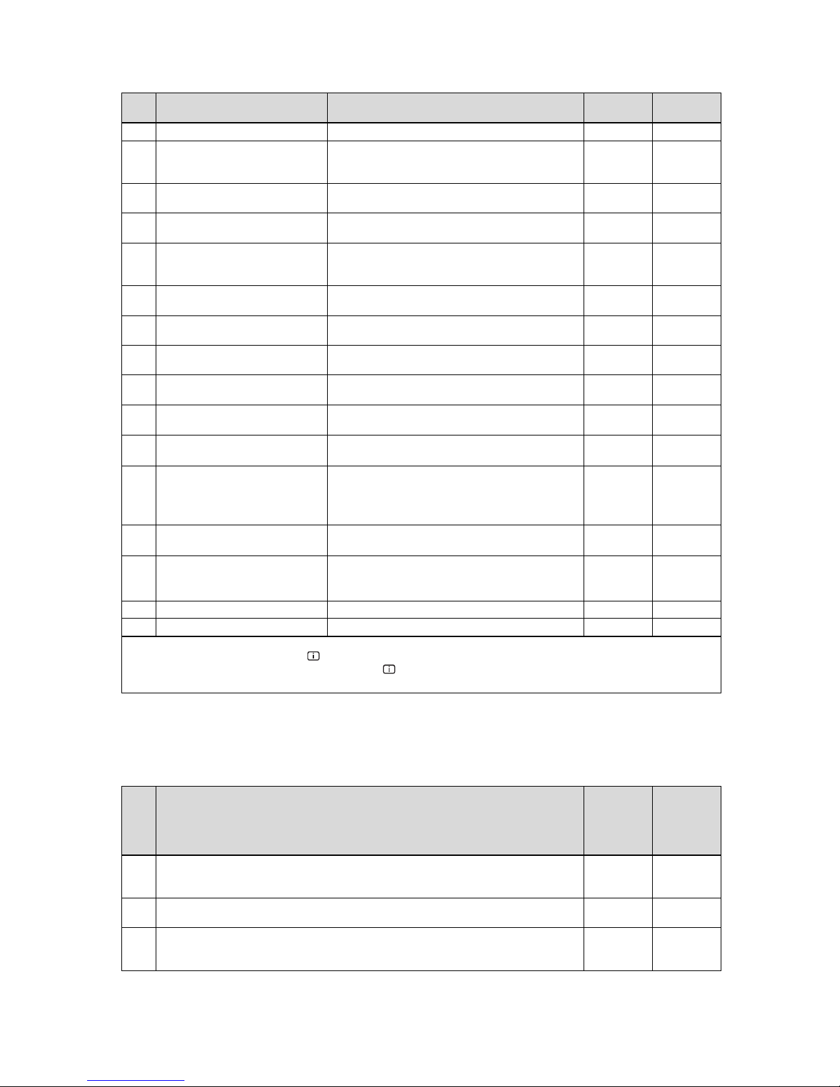
Appendix
32 Installation and maintenance instructions ecoTEC plus 0020029173_04
Code
Parameter Values or explanations
Default setting
Own setting
D.72 Pump overrun after cylinder charging Adjustable from 0 to 600 seconds 80 seconds
D.75 Max. charging time for domestic hot
water cylinder without independent
control system
20 - 90 min 45 minutes
D.76 Unit variant: Device-specific number
(DSN)
VC/VU/VM 656/4‑5 = 47
D.77 Limit on cylinder charging output inkWAdjustable cylinder charging output in kW Maximum
output
D.78 Cylinder charging temperature limit
(target flow temperature in cylinder
charging mode) in °C
55 °C-85 °C 80 ℃
D.80 Operating hours, heating in hrs ¹ Not
adjustable
D.81 Operating hours, hot water genera-
tion
in hrs ¹ Not
adjustable
D.82 Number of burner start-ups in heat-
ing mode
Number of burner start-ups /100 (3 equals 300) ¹ Not
adjustable
D.83 Number of burner start-ups in hot
water mode
Number of burner start-ups /100 (3 equals 300) ¹ Not
adjustable
D.84 Maintenance indicator: Number of
hours until the next maintenance
Adjustment range: 0 to 3000 hrs and "-" for deactivated
300 equals 3000 hrs
„-”
D.90 Status of digital controller 0 = Not recognised (eBUS address ≤ 10)
1 = Recognised
Not
adjustable
D.91 Status of DCF with external temper-
ature sensor connected
0 = No reception
1 = Reception
2 = Synchronised
3 = Valid
Not
adjustable
D.93 Product type setting (device specific
number)
Setting range: 0 to 99
VC/VU/VM 656/4‑5 = 47
D.96 Default setting Reset all adjustable parameters to factory setting
0 = No
1 = Yes
0
d.97 Activating the installer level Service code 17
D.98 Telephone: Competent person Programmable telephone number
1. Five-digit numbers are saved for diagnostics codes 80 to 83. If you select D.80, for example, only the first two digits of the number
will be displayed (e.g. 10). Pressing switches the display to the last three digits (e.g. 947). In this example, the number of operating hours for the heating is 10947 hrs. Pressing the again causes the display to switch back to the diagnostics code that was
called up.
B Inspection and maintenance work – Overview
The table below lists the manufacturer requirements with respect to minimum inspection and maintenance intervals. If national regulations and directives require shorter inspection and maintenance intervals, you should observe these instead of
the intervals listed in the table.
No. Work
Inspection
(annual)
Mainten-
ance
(At least
every
two years)
1
Check the flue pipe for leak-tightness and to ensure that it is fastened correctly. Make sure that
it is not blocked or damaged and has been installed in accordance with the relevant Installation
Manual.
X X
2
Check the general condition of the product. Remove dirt from the product and from the vacuum
chamber.
X X
3
Visually inspect the general condition of the compact thermal module. In doing so, pay particular
attention to signs of corrosion, rust and other defects. If you notice any damage, carry out maintenance work.
X X
Page 33
Appendix
0020029173_04 ecoTEC plus Installation and maintenance instructions 33
No. Work
Inspection
(annual)
Mainten-
ance
(At least
every
two years)
4
Check the gas flow pressure at maximum heat input. If the gas flow pressure is not within the
correct range, carry out maintenance work.
X X
5
Check the CO₂ content (the air ratio) of the product and, if necessary, adjust it. Keep a record of
this.
X X
6
Disconnect the product from the power mains. Check that the electrical plug connections and
other connections are seated correctly and correct these if necessary.
X X
7 Close the gas isolator cock and the service valves. X
8
Drain the product on the water side (observe the pressure gauge). Check the pre-charge pressure of the expansion vessel, and top up the vessel if necessary (approx. 0.03 MPa/0.3 bar under the system filling pressure).
X
9 Remove the compact thermal module. X
10 Install the burner insulation on the back wall of the heat exchanger. X
11 Clean the heat exchanger. X
12
Replace the burner insulation (article number 0020093190) on the back wall of the heat exchanger. Replace the burner insulation each time maintenance work is carried out.
X
13
Check the burner insulation on the burner flange. If you notice any damage, replace the burner
insulation (article number 180913). Replace the burner flange seal (article number 180904) each
time it is opened and, accordingly, each time maintenance work is carried out.
X
14 Check the burner for damage and replace it if necessary. X
15 Check the condensate trap in the product, and clean and fill this, if required. X X
16 Clean the condensate duct in the product. X
17 Install the compact thermal module. Caution: Replace the seals (article number 130904). X
18 Clean the air separation system. X
19 Open the gas isolator cock, reconnect the product to the power mains and switch the product on. X X
20
Open the service valves, fill up the product/heating installation to 0.1-0.2 MPa/1.0-2.0 bar (depending on the static height of the heating installation) and start the purging programme P.0.
X
21
Perform a test operation of the product and heating installation, including hot water generation,
and purge the system once more if necessary.
X X
22 Check the product's gas ratio setting and, if required, reset it. Log the setting. X
23 Visually inspect the ignition and burner behaviour. X X
24 Check the CO₂ content (the air ratio) of the product again. X
25
Ensure that no gas, flue gas, hot water or condensate is leaking from the product. Restore leaktightness if necessary.
X X
26 Record the inspection/maintenance work carried out. X X
C Status codes – Overview
Status code Meaning
Heating mode
S.0 Heating: No heat demand
S.1 Heating mode: Fan start-up
S.2 Heating mode: Pump pre-run
S.3 Heating mode: Ignition
S.4 Heating mode: Burner on
S.5 Heating mode: Pump/fan overrun
S.6 Heating mode: Fan overrun
S.7 Heating mode: Pump overrun
S.8 Heating mode: Remaining anti-cycling time
Cylinder charging mode
S.20 DHW demand
Page 34
Appendix
34 Installation and maintenance instructions ecoTEC plus 0020029173_04
Status code Meaning
S.21 DHW mode: Fan start-up
S.22 DHW mode: Pump pre-run
S.23 DHW mode: Ignition
S.24 DHW mode: Burner on
S.25 DHW mode: Pump/fan overrun
S.26 DHW mode: Fan overrun
S.27 DHW mode: Pump overrun
S.28 Hot water burner anti-cycling time
Special cases
S.30 Room thermostat (RT) is blocking heating mode
S.31
Summer mode active or no heat requirement
from eBUS controller
S.32 Waiting period because of fan speed deviation
S.34 Frost protection mode active
S.36 Reference setting for the continuous controller 7-
8-9 or eBUS controller is < 20 °C and blocks the
heating mode
S.39 Contact thermostat tripped
S.41 Water pressure > 0.28 MPa (2.8 bar)
S.42 Flue non-return flap return signal blocks burner
operation (only in connection with accessories)
or condensate pump faulty, heat requirement is
blocked.
S.53 Product is within the waiting period of the mod-
ulation block/operation block function as a result of low water pressure (flow/return spread too
large)
S.54 Product is within the waiting period of the oper-
ation blocking function as a result of low water
pressure (temperature gradient)
S.59 Waiting period: Minimum volume of circulation
water not achieved
S.85 Service message: "Check circulation water
quantity".
S.96 Return sensor test running, heating demands are
blocked.
S.97 Water pressure sensor test running, heating de-
mands are blocked.
S.98 Flow/return sensor test running, heating de-
mands are blocked.
D Overview of fault codes
Code Meaning Cause
F. 0 Flow temperature sensor interruption NTC plug not plugged in or has come loose, multiple plug on the PCB
not plugged in correctly, interruption in cable harness, NTC defective
F. 1 Return temperature sensor interruption NTC plug not plugged in or has come loose, multiple plug on the PCB
not plugged in correctly, interruption in cable harness, NTC defective
F.10 Flow NTC short circuit NTC defective, short circuit in cable harness, cable/casing
F.11 Return NTC short circuit NTC defective, short circuit in cable harness, cable/casing
F.13 Cylinder temperature sensor short circuit NTC defective, short circuit in cable harness, cable/casing
F.20 Safety switch-off: Temperature limiter Incorrect earth connection between cable harness and product, flow or
return NTC defective (loose connection), black discharge via ignition
cable, ignition plug or ignition electrode
Page 35

Appendix
0020029173_04 ecoTEC plus Installation and maintenance instructions 35
Code Meaning Cause
F.22 Safety switch-off: Low water pressure No or insufficient water in the product, water pressure sensor defective,
cable to pump or water pressure sensor loose/not connected/defective
F.23 Safety switch-off: Temperature difference too
great
Pump blocked, insufficient pump output, air in product, flow and return
NTC connected the wrong way round
F.24 Safety switch-off: Temperature rise too fast Pump blocked, insufficient pump output, air in product, system pressure
too low, non-return valve blocked/incorrectly installed
F.25 Safety switch-off: Flue gas temperature too high Break in plug connection for optional flue gas safety temperature limiter
(STB), break in cable harness
F.27 Safety switch-off: Flame simulation Moisture on the electronics, electronics (flame monitor) defective, gas
solenoid valve leaking
F.28 Failure during start-up: Ignition unsuccessful Gas meter defective or gas pressure monitor has triggered, air in gas,
gas flow pressure too low, thermal isolator device (TAE) has triggered,
condensate duct blocked, incorrect gas restrictor, incorrect spare part
gas valve, fault on the gas valve, multiple plug on PCB incorrectly
plugged in, break in cable harness, ignition system (ignition transformer,
ignition cable, ignition plug, ignition electrode) defective, ionisation
current interrupted (cable, electrode), incorrect earthing of product,
electronics defective
F.29 Failure during operation: Re-ignition unsuccess-
ful
Gas supply temporarily stopped, flue gas recirculation, condensate duct
blocked, defective earthing of product, ignition transformer has spark
failure
F.32 Fan fault Plug on fan not correctly plugged in, multiple plug on PCB not correctly
plugged in, break in cable harness, fan blocked, Hall sensor defective,
electronics defective
F.49 Fault: eBUS Short circuit on eBUS, eBUS overload or two power supplies with differ-
ent polarities on the eBUS
F.61 Gas valve actuation fault The gas valve cannot be actuated
– Cable harness supply line to the gas valve is defective (short to
earth, short circuit)
– Gas valve defective
– PCB defective
F.62 Gas valve switch-off delay Delayed shutdown of gas valve detected
– Secondary light (ignition and monitoring electrode indicates delayed
extinguishing of the flame signal)
– Gas valve defective
– PCB defective
F.63 Fault: EEPROM Electronics defective
F.64 Fault: Electronics/NTC Flow or return NTC short circuited, electronics defective
F.65 Fault: Electronics temp. Electronics overheating due to external influences, electronics defective
F.67 Fault: Electronics/flame Implausible flame signal, electronics defective
F.70 Invalid device specific number (DSN) If spare parts fitted: Display and PCB replaced at same time and DSN
not reset, incorrect or missing output range coding resistance
F.71 Flow NTC fault Flow temperature sensor signalling constant value:
– Flow temperature sensor incorrectly positioned at supply pipe
– Flow temperature sensor defective
F.72 Flow/return NTC fault Flow/return NTC temperature difference too great → flow and/or return
temperature sensor defective
F.73 Water pressure sensor signal in the wrong range
(too low)
Interruption/short circuit of water pressure sensor, interruption/short
circuit to GND in supply line to water pressure sensor or water pressure
sensor defective
F.74 Water pressure sensor signal outside correct
range (too high)
Line to water pressure sensor has a short circuit to 5 V/24 V or internal
fault in the water pressure sensor
F.75 Fault: No pressure change detection when start-
ing pump
Water pressure sensor and/or pump defective, air in the heating installation, insufficient water in the product; check adjustable bypass, connect
external expansion vessel to the return
F.77 Fault: Flue non-return flap/condensate pump No response from flue non-return flap or condensate pump defective
con No communication with the PCB Communication fault between display and PCB in the electronics box
Page 36
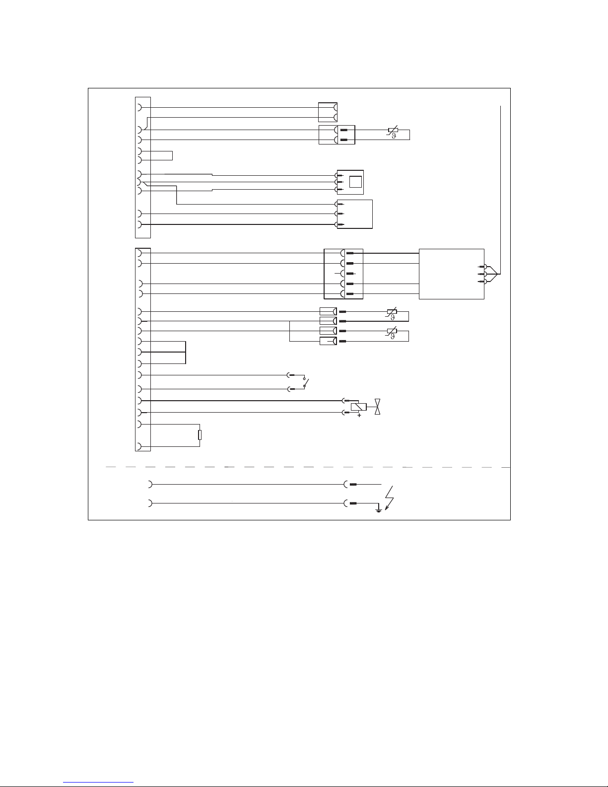
Appendix
36 Installation and maintenance instructions ecoTEC plus 0020029173_04
E Connection diagram
Ignition electrode
Appliance earth
Ignition unit
X14
green/yellow
Cylinder thermostat (accessory)
"C1/C2"
Gas valve
Flow Switch
Flow sensor
Flow sensor
Water pressure sensor
Cylinder sensor
P
Return sensor
Fa n
Mains
X20
X2
Extra-low voltage plug
natural
1
2
4
+
signal
-
1 Earth
2 Hall signal
3
4 PWM signal
5 + 24 V
black
4
2
5
9
11
12
13
1
17
3
4
16
5
7
8
12
13
14
6
10
18
9
15
2
14
10
brown
black
black
black
black
black
black
black
black
black
black
black
grey
red
red
red
blue
blue
blue
green
red
red
green
orange
violet
Coding resistance
1210
X11
Page 37
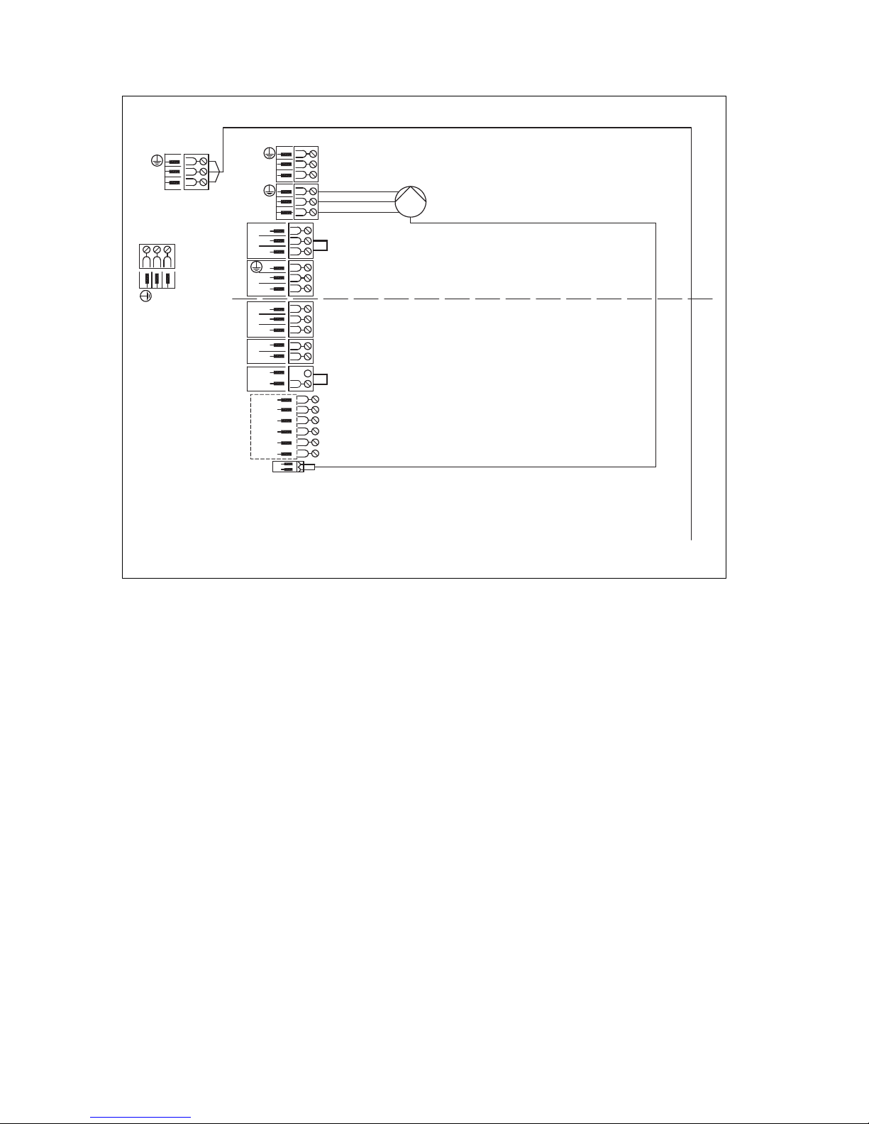
Appendix
0020029173_04 ecoTEC plus Installation and maintenance instructions 37
X13
X11
Fa n
230 V~
N
L
N
L
grey
N
L
blue
green
X18
5
4
3
N
L
9
8
7
+
2
FB
AF
RF
DCF
0
0
1
-
turquoise
violetwhiteredblue
Supply voltageExtra-low voltage
Edge connector
X1
X41
X22
6
1
X6
pink
N
L
Option: Ext. controller/room thermostat 3-4
(Contact)
Option: Ext. controller/room thermostat 7-8-9
(continuous, analogue)
Option: Bus connection (controller/digital room therm.)
Option: Contact thermostat
Mains input
Internal pump
Plug for controller accessory
VRC 4xx or ZP control system
Circulation pump remote control
External sensor
Low loss header sensor
DCF connection
Earth
Earth
PWM signal: Internal pump
24 V 230 V~
Fa n
Auxiliary relay (can be adjusted under D.26)
Cylinder
charging pump
Page 38

Appendix
38 Installation and maintenance instructions ecoTEC plus 0020029173_04
F Commissioning Checklist
© Heating and Hotwater Industry Council (HHIC)
www.centralheating.co.uk
Benchmark Commissioning and
Servicing Section
It is a requirement that the boiler is installed and commissioned to the
completed in full.
Page 39
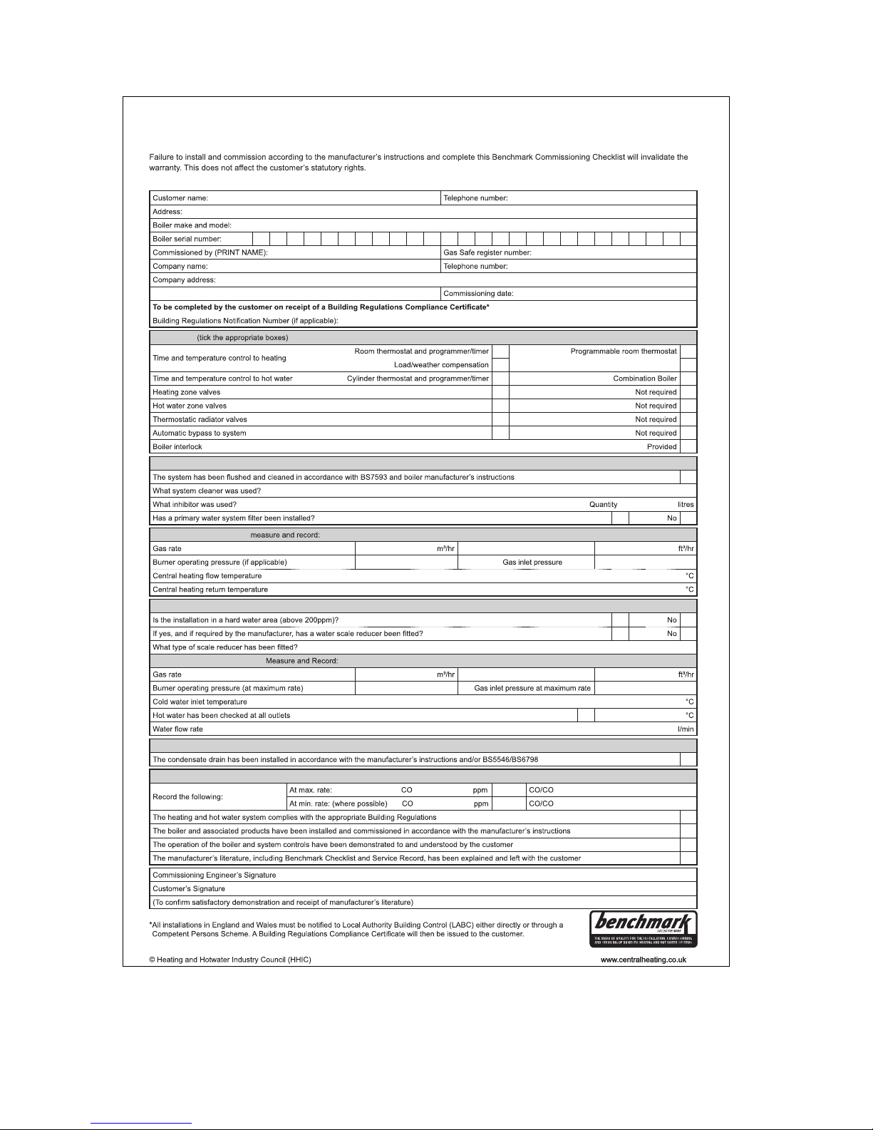
Appendix
0020029173_04 ecoTEC plus Installation and maintenance instructions 39
This Commissioning Checklist is to be completed in full by the competent person who commissioned the boiler as a means of demonstrating
compliance with the appropriate Building Regulations and then handed to the customer to keep for future reference.
GAS BOILER SYSTEM COMMISSIONING CHECKLIST
CONTROLS
Optimum start control
Fitted
Fitted
Fitted
Fitted
ALL SYSTEMS
Yes
Yes
CENTRAL HEATING MODE
OR
mbar OR mbar
COMBINATION BOILERS ONLY
Yes
Yes
DOMESTIC HOT WATER MODE
OR
mbar OR mbar
Yes Temperature
CONDENSING BOILERS ONLY
Yes
ALL INSTALLATIONS
AND
²
Ratio
AND
²
Ratio
Yes
Yes
Yes
Yes
Page 40
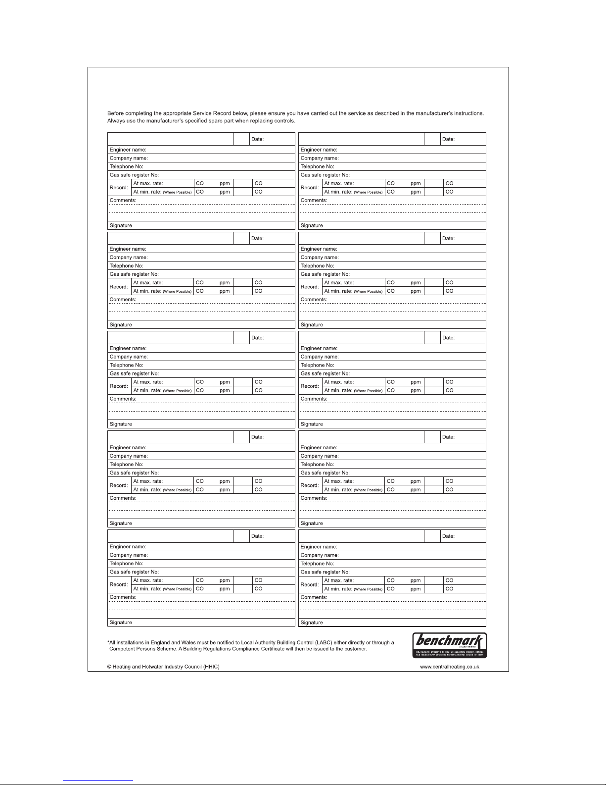
Appendix
40 Installation and maintenance instructions ecoTEC plus 0020029173_04
It is recommended that your heating system is serviced regularly and that the appropriate Service Interval Record is completed.
Service Provider
SERVICE RECORD
SERVICE 01
AND
²
%
AND
²
%
SERVICE 02
AND
²
%
AND
²
%
SERVICE 03
AND
²
%
AND
²
%
SERVICE 04
AND
²
%
AND
²
%
SERVICE 05
AND
²
%
AND
²
%
SERVICE 06
AND
²
%
AND
²
%
SERVICE 07
AND
²
%
AND
²
%
SERVICE 08
AND
²
%
AND
²
%
SERVICE 09
AND
²
%
AND
²
%
SERVICE 10
AND
²
%
AND
²
%
Page 41
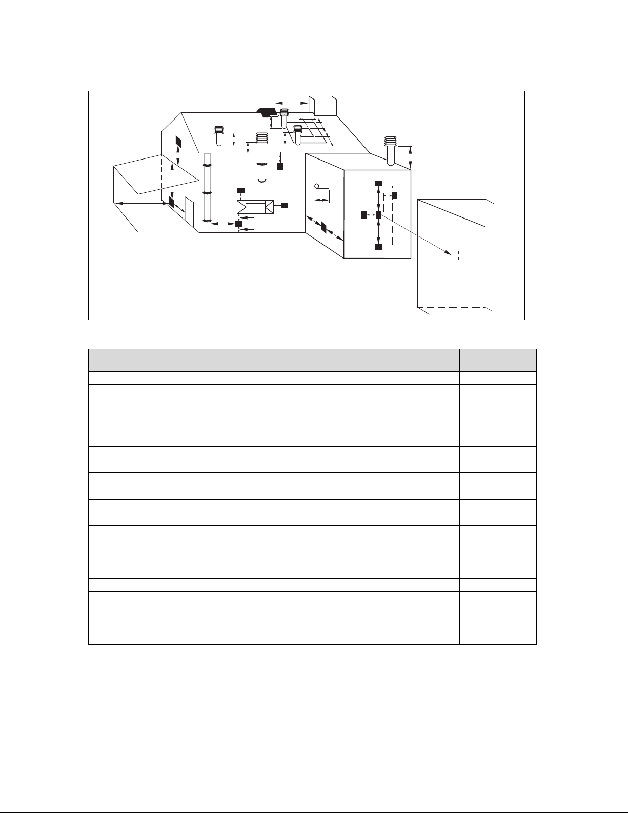
Appendix
0020029173_04 ecoTEC plus Installation and maintenance instructions 41
G Opening of the flue pipe
G
N
N
MM
A
I
I
O
H
H
C
B
L
J
Q
Q
Q
Q
Q
K
P
D, E
F
I
S
R
T
G.1 Positioning of the opening of a fan-supported flue gas guiding
Installation site
Minimum dimensions
A
Directly below an opening, air bricks, opening windows, etc., that can be opened. 300 mm
B Above an opening, air bricks, opening windows, etc., that can be opened. 300 mm
C Horizontally to an opening, air bricks, opening windows, etc., that can be opened. 300 mm
D
Below temperature-sensitive building components, e.g. plastic gutters, down pipes or wastewater
pipes
75 mm
E Below eaves 200 mm
F Below balconies or car port roofs 200 mm
G From vertical wastewater pipes or down pipes 150 mm
H From external or internal corners 200 mm
I Above floors, roofs or balconies 300 mm
J From a surface facing a terminal 600 mm
K From a terminal facing a terminal 1200 mm
L From an opening in the car port (e.g. door, window) which leads into the dwelling 1200 mm
M Vertical from a terminal on the same wall 1500 mm
N Horizontal from a terminal on the same wall 300 mm
O From the wall on which the terminal has been installed 0 mm
P From a vertical structure on the roof N/A
Q Above the roof area 300 mm
R Horizontal from adjacent windows on pitched or flat roofs 600 mm
S Above adjacent windows on pitched or flat roofs 600 mm
T Below adjacent windows on pitched or flat roofs 2000 mm
Page 42

Appendix
42 Installation and maintenance instructions ecoTEC plus 0020029173_04
H Text from BS 5440-1 on fan-supported flue gas guiding
BS 5440–1: It is recommended that the fanned flue gas system terminal is positioned as follows:
– At least 2 m from an opening in the building directly opposite, and
– So that the combustion products are not discharged directly across a property boundary.
– Dimensions D, E, F and G: These clearances may be reduced to 25 mm without affecting the performance of the boiler.
In order to ensure that the condensate vapour plume does not damage adjacent surfaces, the terminal should be extended as shown.
– Dimension H: This clearance may be reduced to 25 mm without adversely affecting the performance of the boiler. How-
ever, in order to ensure that the condensate vapour plume does not damage adjacent surfaces, a clearance of 300 mm is
preferred. For IE, recommendations are given in the current issue of the IS 813.
I Opening of the flue pipe below eaves and balconies
Balcony/eaves
Gutter
Adequately secured
air/flue gas pipe
The flue pipe must
protrude beyond any overhang
J Technical data
Technical data – Power/load
VU GB 656/4‑5
Nominal heat output range P at 40/30 °C
14.9 … 69.2 kW
Nominal heat output range P at 50/30 °C
14.6 … 67.6 kW
Nominal heat output range P at 60/40 °C
14.1 … 65.7 kW
Nominal heat output range P at 80/60 °C
13.8 … 63.7 kW
Maximum heat input, heating side
65.0 kW
Minimum heat input heating side
14.0 kW
Technical data – Heating
VU GB 656/4‑5
Maximum flow temperature
90 ℃
Max. flow temperature adjustment range (default setting:
75 °C)
35 … 85 ℃
Permissible total overpressure
0.3 MPa
(3.0 bar)
Circulation water volume (with reference to ΔT= 20 K)
2,750 l/h
Approx. condensate rate (pH value approx. 3.7) in heating mode at 40/30 °C
6.5 l/h
Technical data – cylinder charging mode
VU GB 656/4‑5
Maximum heat input in cylinder charging mode
65.0 kW
Cylinder charging output
Such as heating
Page 43

Appendix
0020029173_04 ecoTEC plus Installation and maintenance instructions 43
Technical data – General
VU GB 656/4‑5
Approved unit category
I
2H
Gas connection, boiler side
1″
Flow/return heating connections, inside thread, boiler
side
1″
Flow/return heating connections, outside thread, boiler
side
1,5″
Air/flue gas connection
80/125 mm
Gas connection pressure, G20 natural gas
2.0 kPa
(20.0 mbar)
Gas flow at 15 °C and 1013 mbar (based on hot water
generation if applicable), G20
6.9 m³/h
Min. flue gas mass rate
6.5 g/s
Max. flue gas mass rate
30.3 g/s
Min. flue gas temperature
40 ℃
Max. flue gas temperature
70 ℃
Approved gas-fired units
C13, C33, C43, C53, C83,
C93, B23, B33, B33P
30% efficiency
108 %
NOx class
5
Boiler dimension, width
480 mm
Boiler dimension, height
800 mm
Boiler dimension, depth
472 mm
Approx. net weight
75 kg
Technical data – Electrics
VU GB 656/4‑5
Rated voltage
230 V/50 Hz
Built-in fuse (slow-blow)
2 A
Max. electrical power consumption
260 W
Electrical power consumption, 30%
160 W
Level of protection
IP X4 D
Test symbol/registration no.
CE-0085BS0402
Page 44

Index
44 Installation and maintenance instructions ecoTEC plus 0020029173_04
Index
A
Air index setting ................................................................... 20
Air separator........................................................................ 26
Air separator, filter ...............................................................26
Air/flue pipe ......................................................................... 14
Air/flue pipe, installed ............................................................ 5
Article number ....................................................................... 8
Automatic air vent................................................................18
B
Burner anti-cycling time ....................................................... 23
C
Calling up diagnostics codes...............................................22
Carrying out inspection work ............................................... 24
Carrying out maintenance work........................................... 24
CE label................................................................................. 8
Check programmes.............................................................16
Checking the burner ............................................................26
Checking the CO₂ content ................................................... 20
Checking the pre-charge pressure of the expansion
vessel ..................................................................................27
Circulation pump ................................................................. 16
Cleaning the condensate duct and the condensate trap..... 26
Combustion air ...................................................................... 6
Compact thermal module ................................................ 6, 24
Completing inspection work ................................................27
Completing maintenance work ............................................ 27
Completing repair work .......................................................28
Completing, repair work ......................................................28
Condensate drain pipework................................................. 13
Condensate duct ................................................................. 26
Connecting the controller ....................................................15
Connection dimensions ......................................................... 9
Corrosion............................................................................... 6
Corrugated gas pipe .............................................................. 6
D
Decommissioning................................................................28
Decommissioning the product ............................................. 28
Descaling the heat exchanger............................................. 25
Descaling, heat exchanger.................................................. 25
Diagnostics level ................................................................. 22
Disposal, packaging ............................................................ 28
Disposing of the packaging ................................................. 28
Documents ............................................................................8
Draining the product ............................................................27
E
Electricity ............................................................................... 5
Expansion relief valve .........................................................13
F
Fault codes.................................................................... 27, 34
Fault memory ...................................................................... 28
Filling the condensate trap .................................................. 19
Filling the heating installation .............................................. 18
Filling, heating installation ................................................... 18
Filter, air separator .............................................................. 26
Flow temperature, maximum............................................... 23
Flue gas route .......................................................................5
From the delivery point to the installation site ....................... 9
Front casing, closed .............................................................. 5
Frost ......................................................................................6
G
Gas connection ................................................................... 12
Gas ratio setting .................................................................. 19
H
Handing the product over to the operator............................ 23
Handling ................................................................................9
Heat exchanger...................................................................25
Heating flow.........................................................................13
Heating partial load .............................................................22
Heating return......................................................................13
Hot water temperature, risk of scalding................................. 5
I
Identification plate ................................................................. 8
If you smell gas .....................................................................4
Inspection and maintenance intervals ................................. 24
Installation clearances ......................................................... 10
Installation site................................................................... 5–6
Installer level ....................................................................... 22
Installing the compact thermal module................................ 27
Installing the front casing..................................................... 11
Intended use..........................................................................4
L
Leak detection spray ............................................................. 6
M
Mains connection ................................................................ 15
Maintenance interval ........................................................... 23
Minimum clearances ........................................................... 10
P
Performing diagnostics ........................................................ 28
Power supply....................................................................... 15
Preparing the repair work .................................................... 28
Product dimensions............................................................... 9
Pump operating mode .........................................................22
Pump overrun...................................................................... 22
Purging the heating installation ........................................... 18
Purging, heating installation ................................................ 18
R
Reading off the filling pressure............................................ 17
Regulations ........................................................................... 6
Removing the condensate trap ........................................... 26
Replacing the burner ...........................................................28
Replacing the display .......................................................... 28
Replacing the PCB ..............................................................28
Replacing, display ............................................................... 28
Replacing, PCB ................................................................... 28
Resetting parameters .......................................................... 28
Resetting, all parameters ....................................................28
S
Safety device......................................................................... 5
Schematic drawing ................................................................ 5
Second diagnostics level ..................................................... 22
Serial number........................................................................8
Service partner....................................................................27
Setting the CO₂ content....................................................... 20
Spare parts.......................................................................... 24
Supply of combustion air ....................................................... 5
Switching on the product ..................................................... 16
T
Tool ....................................................................................... 6
Transport ............................................................................... 6
Treating the heating water .................................................. 17
Page 45

Index
0020029173_04 ecoTEC plus Installation and maintenance instructions 45
U
Unloading the box .................................................................9
V
Voltage ..................................................................................5
W
Wall-mounting the product ..................................................10
Page 46

Page 47

Page 48

0020029173_04 26.03.2015
Vaillant Ltd
Nottingham Road Belper Derbyshire DE56 1JT
Telephone 44 84 56 02 29 22 Vaillant Service Solutions 44 807 06 06 07 77
Spares Technical Enquiries 44 17 73 59 66 15
info@vaillant.co.uk technicalspares@groupservice.co.uk
www.vaillant.co.uk
© These instructions, or parts thereof, are protected by copyright and may be reproduced or distributed only with
the manufacturer's written consent.
 Loading...