

Vaillant ecoTEC plus VU GB 5-5 Series, ecoTEC plus VU GB 1006/5-5, ecoTEC plus VU GB 1206/5-5, ecoTEC plus VU GB 806/5-5 Installation And Maintenance Instructions Manual
Page 1
Installation and maintenance instructions
Publisher/manufacturer
Vaillant GmbH
Berghauser Str. 40 D-42859 Remscheid
Tel. +492191 18 0 Fax +492191 18 2810
info@vaillant.de www.vaillant.de
ecoTEC plus
VU GB .../5‑5
GB, IE
Page 2

Contents
Contents
1 Safety .................................................................... 4
1.1 Action-related warnings ......................................... 4
1.2 Intended use.......................................................... 4
1.3 General safety information .................................... 4
1.4 Regulations (directives, laws, standards) .............. 6
2 Notes on the documentation .............................. 7
2.1 Observing other applicable documents ................. 7
2.2 Storing documents................................................. 7
2.3 Validity of the instructions...................................... 7
2.4 Benchmark............................................................. 7
3 Product description............................................. 7
3.1 Design of the product............................................. 7
3.2 Information on the data plate................................. 8
3.3 CE marking ............................................................ 8
4 Set-up.................................................................... 8
4.1 Unpacking the product........................................... 8
4.2 Checking the scope of delivery.............................. 8
4.3 Product dimensions and connection
dimensions............................................................. 9
4.4 Minimum clearances and installation
clearances ............................................................. 9
4.5 Using the mounting template................................. 9
4.6 Wall-mounting the product..................................... 9
4.7 Removing/installing the front casing.................... 10
4.8 Removing/installing the upper casing.................. 10
4.9 Removing/installing the side section (as
required) .............................................................. 11
5 Installation.......................................................... 11
5.1 Gas installation .................................................... 11
5.2 Hydraulics installation.......................................... 12
5.3 Flue installation.................................................... 15
5.4 Electrical installation ............................................ 15
6 Operation............................................................ 18
6.1 Operating concept of the product ........................ 18
6.2 Live Monitor (status codes) ................................. 18
6.3 Test programmes................................................. 18
7 Start-up ............................................................... 18
7.1 Auxiliary service equipment................................. 18
7.2 Carrying out the initial start-up............................. 18
7.3 Checking and treating the heating water/filling
and supplementary water .................................... 18
7.4 Switching on the product ..................................... 19
7.5 Running the installation assistants ...................... 19
7.6 Restarting the installation assistants ................... 20
7.7 Calling up unit configuration and diagnostics
menu.................................................................... 20
7.8 Using check programmes.................................... 20
7.9 Reading off the filling pressure ............................ 20
7.10 Preventing low water pressure ............................ 20
7.11 Flushing the heating system for the first time
("cold") ................................................................. 21
7.12 Filling and purging the heating system ................ 21
7.13 Filling the condensate trap .................................. 21
7.14 Checking and adjusting the gas setting............... 22
7.15 Checking leak-tightness ...................................... 24
7.16 Thoroughly flushing the heating system
("hot")................................................................... 25
8 Adapting the unit to the heating
installation.......................................................... 25
8.1 Calling up diagnostics codes ............................... 25
8.2 Setting the partial heat load ................................. 25
8.3 Setting the pump overrun .................................... 25
8.4 Setting the maximum flow temperature ............... 25
8.5 Setting the return temperature control system .... 26
8.6 Burner anti-cycling time ....................................... 26
8.7 Setting the maintenance interval ......................... 26
8.8 Pump output (high-efficiency pump).................... 26
8.9 Handing the product over to the end user ........... 28
9 Inspection and maintenance ............................ 28
9.1 Observing inspection and maintenance
intervals ............................................................... 28
9.2 Procuring spare parts .......................................... 29
9.3 Using the function menu...................................... 29
9.4 Carrying out electronics self-tests ....................... 29
9.5 Removing the gas-air mixture unit....................... 29
9.6 Cleaning the heat exchanger............................... 31
9.7 Checking the burner ............................................ 31
9.8 Replacing the ignition and ionisation
electrodes ............................................................ 31
9.9 Cleaning the condensate trap.............................. 32
9.10 Installing the gas-air mixture unit......................... 32
9.11 Draining the product ............................................ 33
9.12 Completing inspection and maintenance work .... 33
10 Troubleshooting ................................................ 33
10.1 Contacting your service partner........................... 33
10.2 Calling up service messages............................... 33
10.3 Reading off the fault codes .................................. 33
10.4 Querying the fault memory .................................. 33
10.5 Resetting the fault memory.................................. 34
10.6 Performing diagnostics ........................................ 34
10.7 Using check programmes.................................... 34
10.8 Resetting parameters to factory settings ............. 34
10.9 Preparing the repair work .................................... 34
10.10 Replacing defective components......................... 34
10.11 Completing repair work........................................ 36
11 Decommissioning.............................................. 36
11.1 Decommissioning the product ............................. 36
12 Recycling and disposal..................................... 36
13 Customer service............................................... 36
Appendix ............................................................................ 37
A Installer level menu structure – Overview....... 37
B Overview of diagnostics codes........................ 39
C Inspection and maintenance work –
Overview............................................................. 41
D Status codes – Overview .................................. 42
E Overview of fault codes .................................... 43
2 Installation and maintenance instructions ecoTEC plus 0020134823_07
Page 3

F Wiring diagram................................................... 45
G Initial start-up checklist..................................... 46
G.1 Initial start-up checklist ........................................ 46
H Commissioning Checklist................................. 49
I Position of the opening in the air/flue pipe ..... 52
I.1 Notes ................................................................... 52
I.2 Positioning of the opening of a fan-supported
flue system........................................................... 52
I.3 Horizontal terminal positioning ............................ 53
J Treating the heating water................................ 54
K Technical data.................................................... 55
Index ................................................................................... 57
Contents
0020134823_07 ecoTEC plus Installation and maintenance instructions 3
Page 4
1 Safety
1 Safety
1.1 Action-related warnings
Classification of action-related warnings
The action-related warnings are classified in
accordance with the severity of the possible
danger using the following warning signs and
signal words:
Warning symbols and signal words
Danger!
Imminent danger to life or risk of
severe personal injury
Danger!
Risk of death from electric shock
Warning.
Risk of minor personal injury
Caution.
Risk of material or environmental
damage
1.2 Intended use
There is a risk of injury or death to the user or
others, or of damage to the product and other
property in the event of improper use or use
for which it is not intended.
The product is intended as a heat generator
for closed heating installations and for domestic hot water generation.
Intended use also covers installation in accordance with the IP code.
Any other use that is not specified in these
instructions, or use beyond that specified in
this document, shall be considered improper
use. Any direct commercial or industrial use
is also deemed to be improper.
Caution.
Improper use of any kind is prohibited.
1.3 General safety information
1.3.1 Risk caused by inadequate qualifications
The following work must only be carried out
by competent persons who are sufficiently
qualified to do so:
– Set-up
– Dismantling
– Installation
– Start-up
– Inspection and maintenance
– Repair
– Decommissioning
▶ Proceed in accordance with current tech-
nology.
1.3.2 Risk of injury due to the heavy weight of the product
The product must only be installed in installations that have system separation (plate heat
exchanger).
Depending on the unit type, the products
referred to in these instructions must only be
installed and operated in conjunction with the
air/flue pipe accessories listed in the other
applicable documents.
Intended use includes the following:
– observance of accompanying operating,
installation and maintenance instructions
for the product and any other system components
– installing and setting up the product in ac-
cordance with the product and system approval
– compliance with all inspection and main-
tenance conditions listed in the instructions.
The product weighs over 50 kg.
▶ Make sure that the product is carried by at
least two people.
▶ Use suitable transport and lifting equip-
ment, in accordance with your risk assessment.
▶ Use suitable personal protective equip-
ment: Gloves, safety footwear, protective
goggles, protective helmet.
1.3.3 Risk of death due to lack of safety devices
The basic diagrams included in this document do not show all safety devices required
for correct installation.
▶ Install the necessary safety devices in the
installation.
▶ Observe the applicable national and inter-
national laws, standards and directives.
4 Installation and maintenance instructions ecoTEC plus 0020134823_07
Page 5

Safety 1
1.3.4 Risk of death due to cabinet-type casing
Cabinet-type casing can give rise to dangerous situations when used on a product which
is operated with an open flue.
▶ Ensure that the product is supplied with
sufficient combustion air.
1.3.5 Risk of death from escaping gas
What to do if you smell gas in the building:
▶ Avoid rooms that smell of gas.
▶ If possible, open doors and windows fully
and ensure adequate ventilation.
▶ Do not use naked flames (e.g. lighters,
matches).
▶ Do not smoke.
▶ Do not use any electrical switches, mains
plugs, doorbells, telephones or other communication systems in the building.
▶ If it is safe to do so, close the emergency
control valve or the main isolator.
▶ If possible, close the gas stopcock on the
product.
▶ Warn other occupants in the building by
yelling or banging on doors or walls.
▶ Leave the building immediately and ensure
that others do not enter the building.
▶ Notify the gas supply company or the Na-
tional Grid +44 (0) 800 111999 by telephone once you are outside of the building.
1.3.6 Risk of damage to the flexible gas pipe
The corrugated gas pipe may become damaged if weight is placed on it.
▶ Do not suspend the compact thermal
module on the flexible gas pipe, for
example during maintenance work.
1.3.7 Risk of death from leaks if the product is installed below ground level
▶ Make sure that liquid gas cannot escape
from the product or the gas pipe under any
circumstances.
1.3.8 Risk of death due to blocked or leaking flue gas routes
Installation errors, damage, tampering, impermissible installation sites or similar can cause
flue gas to escape and result in a risk of poisoning.
What to do if you smell flue gas in the property:
▶ Open all accessible doors and windows
fully to provide ventilation.
▶ Switch off the product.
▶ Check the flue gas routes in the product
and the flue gas diversions.
1.3.9 Risk of death from escaping flue gas
If you operate the product with an empty condensate trap / siphon, then flue gas may escape into the room air.
▶ In order to operate the product, ensure that
the condensate trap / siphon is always full.
Condition: Permitted B23 or B23P unit
types with condensate siphon (third-party
accessory)
– Water seal level: ≥ 200 mm
1.3.10 Risk of death due to explosive and
flammable materials
▶ Do not use the product in storage rooms
that contain explosive or flammable substances (such as petrol, paper or paint).
1.3.11 Risk of poisoning caused by
insufficient combustion air supply
Condition: Open-flued operation
▶ Ensure that the air supply to the product's
installation room is permanently unobstructed and sufficient in accordance with the
relevant ventilation requirements.
Liquid gas accumulates at floor level. If the
product is installed below ground level, liquid
1.3.12 Risk of corrosion damage due to
unsuitable combustion and room air
gas may accumulate at floor level if there
are any leaks. In this case, there is a risk of
explosion.
Sprays, solvents, chlorinated cleaning
agents, paint, adhesives, ammonia compounds, dust or similar substances may lead
0020134823_07 ecoTEC plus Installation and maintenance instructions 5
Page 6

1 Safety
to corrosion on the product and in the flue
system.
▶ Ensure that the supply of combustion air is
always free of fluorine, chlorine, sulphur,
dust, etc.
▶ Ensure that no chemical substances are
stored at the installation site.
▶ If you are installing the product in
hairdressing salons, painter's or joiner's
workshops, cleaning businesses or similar
locations, choose a separate installation
room in which the room air is technically
free of chemical substances.
1.3.13 Risk of poisoning and burns caused by escaping hot flue gases
▶ Only operate the product if the air/flue pipe
has been completely installed.
▶ With the exception of short periods for
testing purposes, only operate the product
when the front casing is installed and
closed.
1.3.18 Risk of scalding from hot water
There is a risk of scalding at the domestic
hot water draw-off points if the domestic hot
water temperatures are greater than 60 °C.
Young children and elderly persons are particularly at risk, even at lower temperatures.
▶ Select a moderate set target temperature.
1.4 Regulations (directives, laws, standards)
▶ Observe the national regulations, stand-
ards, directives, ordinances and laws.
1.3.14 Risk of death from electric shock
There is a risk of death from electric shock if
you touch live components.
Before commencing work on the product:
▶ Disconnect the product from the power
supply by switching off all power supplies
at all poles (electrical partition with a contact gap of at least 3 mm, e.g. fuse or circuit breaker).
▶ Secure against being switched back on
again.
▶ Check that there is no voltage.
1.3.15 Risk of material damage caused by frost
▶ Do not install the product in rooms prone
to frost.
1.3.16 Risk of material damage caused by using an unsuitable tool
▶ Use the correct tool.
1.3.17 Risk of being burned or scalded by hot components
▶ Only carry out work on these components
once they have cooled down.
6 Installation and maintenance instructions ecoTEC plus 0020134823_07
Page 7
Notes on the documentation 2
1
2
3
4
6
5
7
8
10
9
12
13
14
15
16
11
2 Notes on the documentation
2.1 Observing other applicable documents
▶ Always observe all the operating and installation instruc-
tions included with the system components.
2.2 Storing documents
▶ Pass these instructions and all other applicable docu-
ments on to the end user.
2.3 Validity of the instructions
These instructions apply only to:
Product article number
Article number
806 (VU GB 806/5‑5)
1006 (VU GB 1006/5‑5)
1206 (VU GB 1206/5‑5)
0010010767 41-044-68
0010010780 41-044-69
0010010791 41-044-70
2.4 Benchmark
Vaillant is a licensed member of the Benchmark Scheme.
Benchmark places responsibilities on both manufacturers
and installers. The purpose is to ensure that customers are
provided with the correct equipment for their needs, that it is
installed, commissioned and serviced in accordance with the
manufacturer’s instructions by a competent person approved
at the time by the Health and Safety Executive and that it
meets the requirements of the appropriate Building Regulations. The Benchmark Checklist can be used to demonstrate compliance with Building Regulations and should be
provided to the customer for future reference.
Installers are required to carry out installation, commissioning and servicing work in accordance with the Benchmark
Code of Practice which is available from the Heating and
Hotwater Industry Council who manage and promote the
Scheme.
Benchmark is managed and promoted by the Heating and
Hotwater Industry Council.
Gas Council
Number
3 Product description
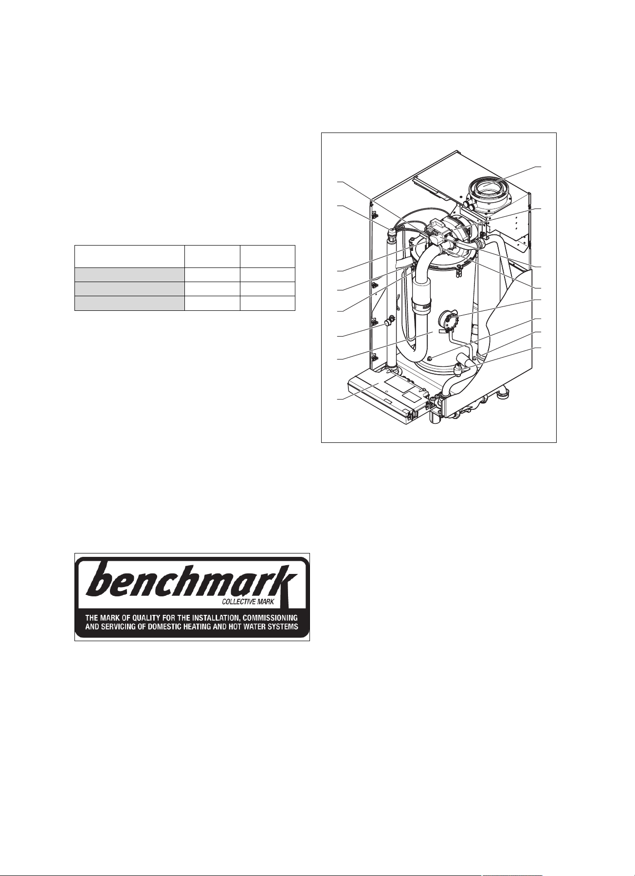
3.1 Design of the product
3.1.1 Functional elements (806/5‑5)
1 Connection for the
air/flue pipe
2 Fan
3 Gas valve assembly
4 Connection for air in-
take pipe
5 Flue pressure switch
6 Return temperature
sensor
7 Safety cut-out (flue gas)
8 Water pressure sensor
9 Electronics box
10 Integral condensation
heat exchanger
11 Manometer
12 Flow temperature
sensor
13 Safety cut-out
14 Ignition electrode
15 Automatic air vent
16 Monitoring electrode
For more information visit www.centralheating.co.uk
0020134823_07 ecoTEC plus Installation and maintenance instructions 7
Page 8
4 Set-up
1
2
3
6
7
5
4
8
10
9
12
13
14
15
16
11
3.1.2 Functional element (1006/5‑5 and 1206/5‑5)
Information on the
identification plate
IP (e.g. X4D) Level of protection
P Nominal heat output range
Q Heat input range
Meaning
Heating mode
Note
Make absolutely sure that the product is compatible with the gas group at the installation site.
3.3 CE marking
The CE marking shows that the products comply with the
basic requirements of the applicable directives as stated on
the data plate.
The declaration of conformity can be viewed at the manufacturer's site.
4 Set-up
For fault-free operation and a long service life for the
1 Connection for the
air/flue pipe
2 Fan
3 Gas pipe
4 Supply air connector
5 Flue pressure switch
6 Return temperature
sensor
7 Safety cut-out (flue gas)
8 Water pressure sensor
9 Electronics box
10 Integral condensation
heat exchanger
11 Manometer
12 Flow temperature
sensor
13 Safety cut-out
14 Ignition electrode
15 Automatic air vent
16 Monitoring electrode
3.2 Information on the data plate
The data plate is mounted on the underside of the product at
the factory.
Information on the
identification plate
Serial number for identification; 7th to 16th digits =
VU… Vaillant gas-fired wall-hung boiler for
ecoTEC plus Product designation
H, G20 – 20 mbar
(2.0 kPa)
Cat. (e.g. II
Types (e.g. C33) Gas-fired boiler types
PMS (e.g. 6 bar
(0.6 MPa))
T
(e.g. 85 °C) Max. flow temperature
max.
230 V 50 Hz Electric connection
(e.g. 260) W Max. electrical power consumption
) Unit category
2H3P
Meaning
product article number
heating
Gas group and gas connection pressure
as set at the factory
Permissible total overpressure
product, you must only install the product in installations with
system separation (plate heat exchanger).
4.1 Unpacking the product
1. Remove the product from its box.
2. Remove the protective film from all parts of the product.
4.2 Checking the scope of delivery
▶ Check that the scope of delivery is complete and intact.
4.2.1 Scope of delivery
Number
1
1
1
1 Condensate discharge hose
1
1
1
1
1
1
1
1
1
1
Designation
Unit mounting bracket
Heat generator
Condensate trap
Mounting template
Enclosed documentation
Enclosed unit fastening
Bag with small parts
Gas connector
Service valve (1 1/2 inches), red handle
Service valve (1 1/2 inches), blue handle
Bag with seals for service valves
Expansion relief valve, 6 bar
R 1 straight-through gas valve
8 Installation and maintenance instructions ecoTEC plus 0020134823_07
Page 9
Set-up 4
287
190
673
603
480
175
138
172 172
70
22
482
Ø25
49
G 1 1/4
960
477
680,5
1
2
3
4
5
6
7
CC
AB
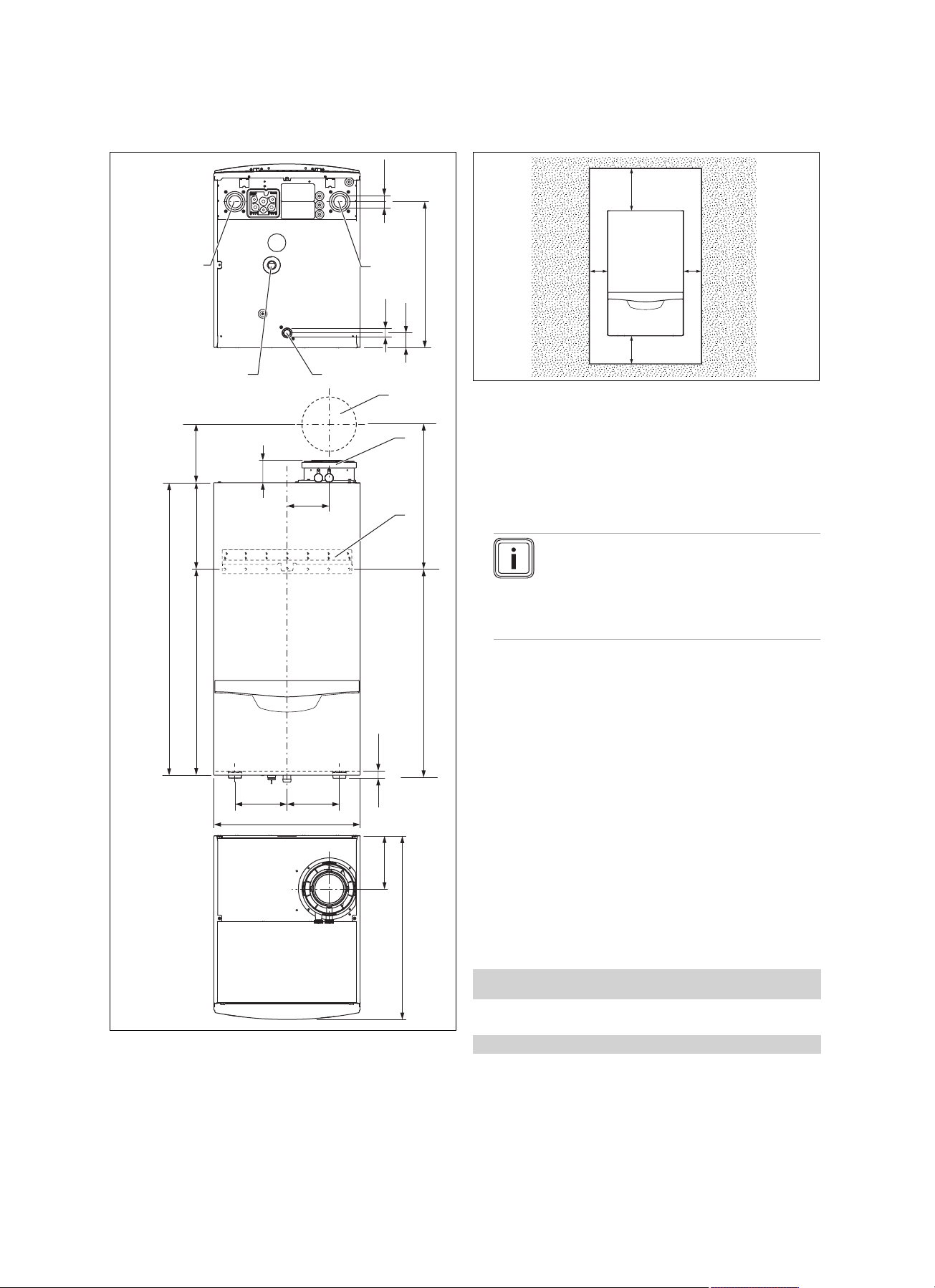
4.3 Product dimensions and connection dimensions
4.4 Minimum clearances and installation clearances
A 350 mm (110/160 mm
diameter flue pipe)
At least 450 mm for
cascade design
B 400 mm
C Optional approx. 200
mm
D Clearance of 600 mm
in front of the product
for easy access during
maintenance work
▶ When using the accessories, observe the minimum clear-
ances/installation clearances.
Note
A lateral clearance is not required, however
you can also remove the side sections if there
is sufficient space at the side (approx. 200
mm) in order to facilitate maintenance or repair work.
▶ Where units are installed in cascade, observe the gradi-
ent of the flue pipe (approx. 50 mm/m).
It is not necessary to maintain a clearance between the
product and components made of combustible materials that
go beyond the minimum clearances.
4.5 Using the mounting template
1. Position the mounting template vertically over the in-
stallation site.
2. Secure the template to the wall.
3. Mark on the wall all the points required for your installa-
tion.
4. Remove the mounting template from the wall.
5. Drill all the holes required.
6. Make any breakthroughs necessary.
4.6 Wall-mounting the product
Condition: The load-bearing capacity of the wall is sufficient, The fixing ma-
terial may be used for the wall
▶ Wall-mount the product as described.
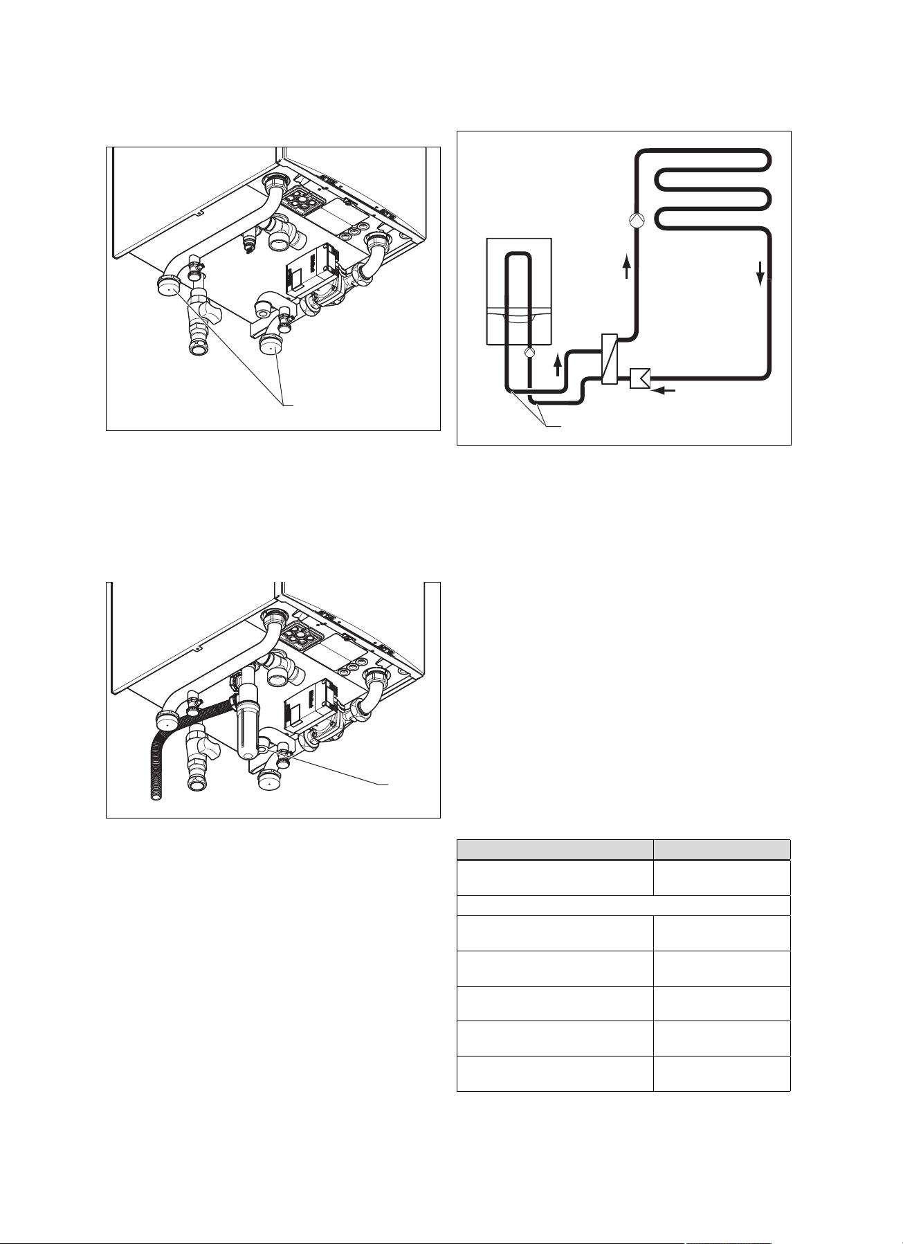
1 Wall duct for flue pipe
2 Flue pipe connection
3 Hanging bracket
4 Heating flow
0020134823_07 ecoTEC plus Installation and maintenance instructions 9
5 Condensate trap con-
nection
6 Gas connection
7 Heating return
Condition: The load-bearing capacity of the wall is not sufficient
▶ Ensure that wall-mounting apparatus on-site has a suf-
ficient load-bearing capacity. Use individual stands or
primary walling, for example.
▶ Do not wall-mount the product if you cannot provide
wall-mounting apparatus with a sufficient load-bearing
capacity.
Page 10
4 Set-up
1
2
1
2
1
Condition: The fixing material may not be used for the wall
▶ Wall-mount the product as described using the permitted
fixing material provided on-site.
1. Install the hanging bracket (1) on the wall.
2. Suspend the product on the hanging bracket from
above using the suspension bracket.
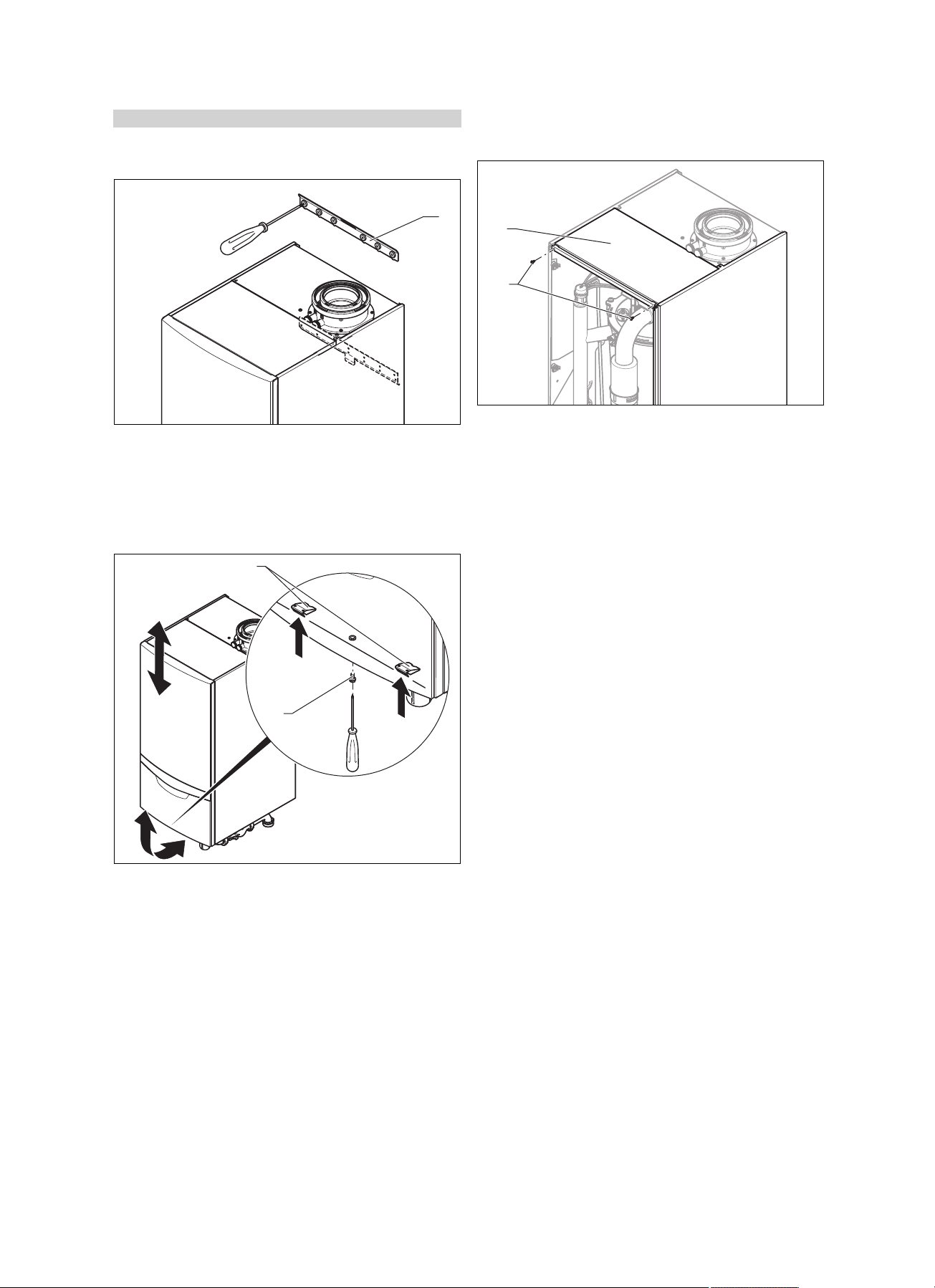
4.7 Removing/installing the front casing
4.7.1 Removing the front casing
4.8 Removing/installing the upper casing
4.8.1 Removing the upper casing
1. Unscrew the screws (2).
2. Pull out the upper casing (1) towards the front.
4.8.2 Installing the upper casing
1. From above, place the upper casing
2. Use the screws (2) to secure the upper casing (1).
(1) on the product.
1. Undo the bolt (1).
2. Push in both retaining clips (2) so that the front casing
is released.
3. Pull the front casing forwards at the bottom edge.
4. Lift the front casing upwards from the bracket.
4.7.2 Installing the front casing
1. Place the front casing on the upper brackets.
2. Push the front casing onto the product until both retaining clips (2) snap into place at the front casing.
3. Secure the front casing by tightening the screw (1).
10 Installation and maintenance instructions ecoTEC plus 0020134823_07
Page 11
Installation 5
4.9 Removing/installing the side section (as required)
4.9.1 Removing the side section
5 Installation
Danger!
Risk of explosion or scalding caused by
incorrect installation.
Mechanical stresses in the connection pipes
may lead to leaks.
▶ Make sure that the connection pipes are
free from mechanical stress when they
are installed.
Caution.
Risk of material damage caused by
residues in the pipelines.
Welding remnants, sealing residues, dirt or
other residues in the pipelines may damage
the product.
▶ Flush the heating installation thoroughly
before installing the product.
Caution.
Risk of material damage caused by
changes to the pipes that have already
been connected.
Caution.
Risk of material damage caused by mech-
anical deformation.
Removing both side sections may cause
mechanical distortion in the product, which
may cause damage to the piping, for example, and potentially result in leaks.
▶ Always only remove one side section –
never both side sections at the same time.
1. Hinge the electronics box forward.
2. Remove the upper casing. (→ Page 10)
3. Hold on to the side section so that it cannot fall, and
unscrew the lower front and upper central screws from
the side section.
4. Hinge the side section slightly to the side and pull it out
towards the front.
4.9.2 Installing the side section
1. Push the side section into the bracket. When doing so,
and to prevent leaks, ensure that all straps on the side
section engage with the back panel.
2. Slide the side section to the rear.
3. Secure the side section using two screws in the front
lower area and in the upper central area.
4. Install the upper casing. (→ Page 10)
5. Hinge up the electronics box.
▶ Only bend connection pipes if they have
not yet been connected to the product.
Seals made of rubber-like materials may be subject to plastic
deformation, which can lead to pressure losses. We recommend using seals made of a paste-like fibre material.
5.1 Gas installation
5.1.1 Performing the gas installation
Caution.
Risk of material damage caused by incor-
rect gas installation.
Excessive test pressure may cause damage
to the gas valve.
▶ When checking the entire gas installation
for leak-tightness, the maximum permissible pressure at the gas valve is 7.5 kPa
(75 mbar).
Caution.
Risk of material damage caused by the
incorrect gas type.
Using the wrong gas type may cause a fault
shutdown of the product. Furthermore, ignition and combustion noise may occur in the
product.
▶ Only use the gas types in accordance with
the data plate.
0020134823_07 ecoTEC plus Installation and maintenance instructions 11
Page 12
5 Installation
▶ Make sure that the existing gas meter is capable of
passing the rate of gas supply required.
▶ Remove the residues from the gas pipe by blowing
through the gas pipe beforehand.
▶ Make sure that the existing gas meter is capable of
passing the rate of gas supply required.
▶ Install an approved gas stopcock on the product using
the gas connector.
▶ Install the gas pipe on the gas stopcock such that it is
free from mechanical stress.
▶ Purge the gas pipe before start-up.
5.1.2 Checking the gas line for leak-tightness
▶ Check the entire gas line properly for leak-tightness.
5.1.3 Information on liquid gas operation
In the as-supplied condition, the product is preset for operation with the gas group indicated on the data plate.
5.1.4 Purging the liquid gas tank
If the liquid gas tank is not purged properly, this may result in
ignition problems.
▶ Ensure that the liquid gas tank has been purged properly
before installing the product.
▶ If required, contact the filler or the liquid gas supplier.
5.2 Hydraulics installation
Caution.
Risk of material damage due to high tem-
peratures.
Plastic pipes in the heating installation may
become damaged by overheating if a fault
occurs.
▶ When using plastic pipes, install a limit
thermostat on the heating flow.
Caution.
Risk of material damage due to heat trans-
fer during soldering.
▶ Only solder connectors if the connectors
are not yet screwed to the service valves.
▶ Please note that water above 150 mg/l CaCO₃ is classi-
fied as hard and the corresponding treatment is required
(→ Page 18).
The product should be connected using a Vaillant pump
group (accessories).
– High-efficiency pump
This pump group has a connection option for an expansion
vessel (right-hand connection) and an expansion relief valve
(left-hand connection). You can find information about available accessories from the Vaillant price list or from the contact address provided on the reverse of this document.
▶ When installing the pump group, observe the installa-
tion sequence for the insulation and the hydraulic pipes (
Pump group installation instructions).
▶ Note that the boiler pump must always be fitted in the
return line. Otherwise, this may lead to a malfunction in
the product.
When connecting several products in cascade operation, you
must install a non-return flap from the cascade connection
set in the flow line of each individual product.
A non-return flap from a third-party manufacturer must have
no more than 30 mbar pressure loss for a volume flow of
4.5 m³/h.
5.1.5 Using the correct gas type
Using the incorrect gas type may cause fault shutdowns in
the product. Ignition and combustion noise may occur in the
product.
▶ Only use the gas type listed on the data plate.
12 Installation and maintenance instructions ecoTEC plus 0020134823_07
Page 13
Installation 5
1
1
Ø 1 1/4"
5.2.1 Connecting the heating flow and heating return
1. In each case, insert a flat seal into the service valve
(Vaillant accessories).
2. Screw the service valves onto the flow and return con-
nection (1) of the pump group.
3. Screw the service valves to the customer's installation.
– Diameter of the heating line: 1 1/4″
5.2.2 Installing the expansion vessels
1. Install a sufficiently dimensioned expansion vessel at
the connection in the boiler circuit return (1) and in the
installation circuit.
– Connection to the pump group: 1/2″
– Large expansion vessel: ≥ 10 l
2. Check that the volumetric capacity of the expansion
vessel in the installation circuit is sufficient for the system volume.
5.2.3 Hydraulic connection
The manufacturer recommends installing the following components in addition to the specified plate heat exchanger for
the hydraulic system separation:
– A dirt filter installed on the installation side upstream of
the plate heat exchanger
– Heating-side cleaning connections for backwashing the
plate heat exchanger during maintenance work
To this end, various plate heat exchangers are available
as accessories, depending on the output of a product or
whether it is a cascade system. The pressure loss is adjusted to the pump groups that are offered as an accessory. The minimum circulation water volume in the unit circuit is only guaranteed if you use original accessories in the
unit circuit, provided that the maximum pressure losses in
the piping are not exceeded. The manufacturer therefore
urgently recommends that you only install original pump
groups.
Select the plate heat exchanger according to output.
Depending on the unit output, different remaining feed heads
(→ Page 26) are available at the boiler circuit's flow pipe.
Observe the following pressure losses (nominal volume flow
at ΔT=20 K):
Power Pressure loss
< 120 kW 86 mbar
(0.086 bar)
In conjunction with the hydraulic cascade
< 240 kW 96 mbar
(0.096 bar)
< 360 kW 76 mbar
(0.076 bar)
< 480 kW 82 mbar
(0.082 bar)
< 600 kW 87 mbar
(0.087 bar)
< 720 kW 92 mbar
(0.092 bar)
0020134823_07 ecoTEC plus Installation and maintenance instructions 13
Page 14
5 Installation
min.
180
2
1
3
1
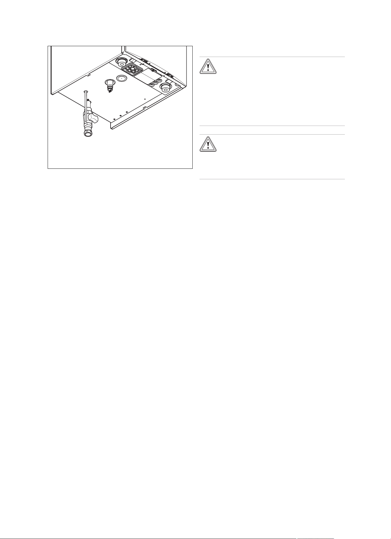
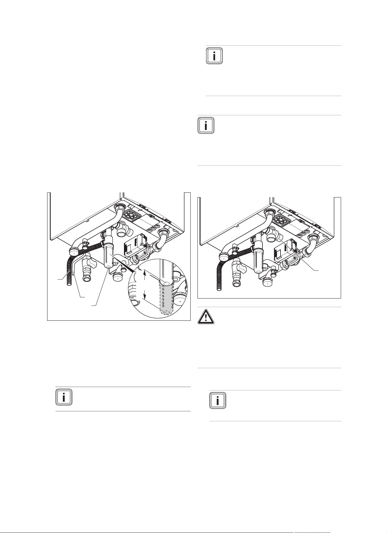
5.2.4 Connecting the condensate trap
Condensate forms in the product during combustion. The
condensate drain pipework routes the condensate to the
waste water connection.
The product is equipped with a condensate trap. The filling
height is 145 mm. The condensate trap collects any condensate that forms and feeds it into the condensate discharge pipe.
▶ Place the condensate trap on the underside of the
product on the condensate drain pipe and secure it using
the retaining clips.
▶ Leave installation space of at least 180 mm below the
condensate trap so that you can clean the condensate
trap in the event of maintenance work.
▶ Before you start up the product, fill the condensate trap
with water (→ Page 21).
▶ Check the connection point for leak-tightness
(→ Page 24).
5.2.5 Connecting the condensate discharge pipe
Note
The condensate drain pipework must have a
continuous fall (45 mm per metre) and should
whenever possible terminate at a suitable
drain point within the heated envelope of the
building that will remain frost free under long
periods of low external temperatures.
5.2.6 Connecting the expansion relief valve
Note
The product is delivered with a 6 bar expansion
relief valve, which must be installed on the
product and must be guided to a secure, but visible, point. The drain pipe on the expansion relief
valve must have a minimum diameter of 28 mm
and must only be used for this purpose.
1. Ensure that all components that are installed in the
heating installation are suitable for a max. operating
pressure of 6 bar.
▶ When making the condensate pipe connections ensure
that there is adequate branch ventilation and that there
can be no backflow of water into the boiler via the condensate pipe work.
▶ Check if a neutralising unit is required in accordance with
national regulations.
▶ Observe the local regulations on neutralising the con-
densate.
Note
You can obtain neutralisation with or without a
condensate pump as an accessory.
▶ If required, guide the drain hose (1) from the automatic
air vent into the tundish.
Danger!
Risk of scalding!
Heating water that leaks from the exit point of
the expansion relief valve may cause severe
scalds.
▶ Install the expansion relief valve drain to a
professional standard.
2. Connect the expansion relief valve (1).
Note
When selecting the expansion relief valve,
note the max. operating pressure of the heating installation.
14 Installation and maintenance instructions ecoTEC plus 0020134823_07
Page 15
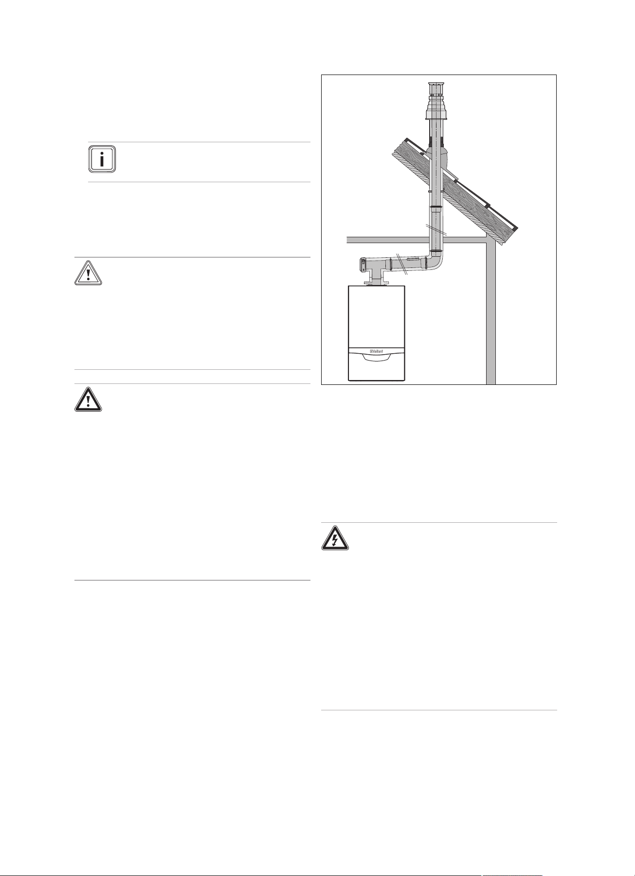
5.3 Flue installation
5.3.1 Air/flue pipes that can be connected
▶ When installing the air/flue pipe, observe the provisions
of the applicable national regulations.
Note
All products feature an 110/160 mm diameter
air/flue connection as standard.
You can find out which air/flue pipes may be used by consulting the enclosed set-up instructions for the air/flue system.
5.3.2 Installing the air/flue pipe
Caution.
Risk of poisoning due to escaping flue
gas.
Mineral-oil-based greases can damage the
seals.
▶ Instead of grease, use only water or com-
mercially available soft soap to aid installation.
Installation 5
Danger!
Risk of personal injury and material dam-
age due to unapproved air/flue pipes.
Vaillant boilers are certified only with Vaillant
original air/flue pipes. The use of other accessories may cause personal injury and material damage, as well as operating faults. For
installation type B23P, third-party accessories are also permitted (see the technical data
in the appendix).
▶ Only use Vaillant original air/flue pipes.
▶ If third-party accessories are permitted
for B23P, ensure that the flue pipe connections are properly routed, sealed and
secured against slipping out.
1. Install the flue pipe using the installation manual.
2. When installing the air/flue pipe, observe the provisions
of the applicable national regulations.
3. Route the flue pipe with a downward gradient so that
the condensate that accumulates can easily flow into
the condensate trap provided for it.
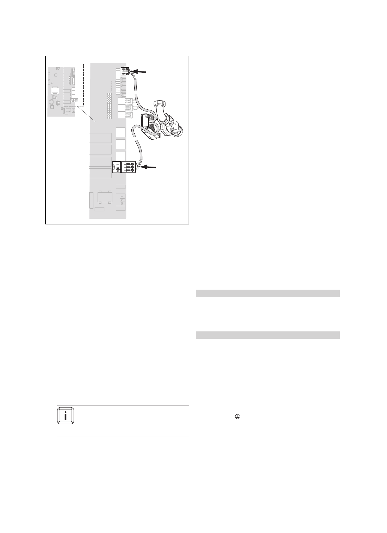
5.4 Electrical installation
Only qualified electricians may carry out the electrical installation.
Danger!
Risk of death from electric shock!
Power supply terminals L and N remain live
even if the on/off button is switched off:
▶ Disconnect the product from the power
supply by switching off all power supplies
at all poles (electrical partition with a contact gap of at least 3 mm, e.g. fuse or circuit breaker).
▶ Secure against being switched back on
again.
▶ Wait for at least 3 minutes until the capa-
citors have discharged.
▶ Check that there is no voltage.
0020134823_07 ecoTEC plus Installation and maintenance instructions 15
Page 16
5 Installation
2
1
3
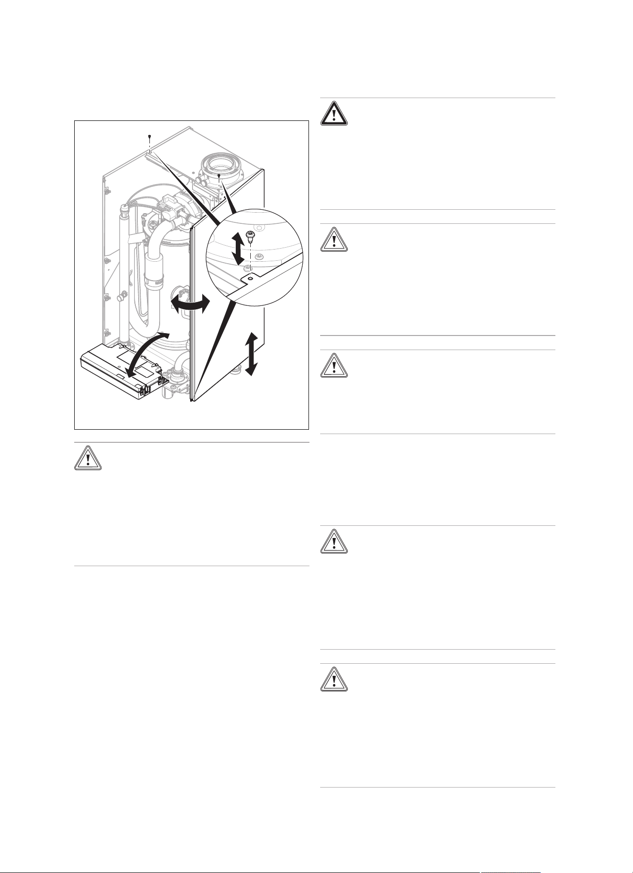
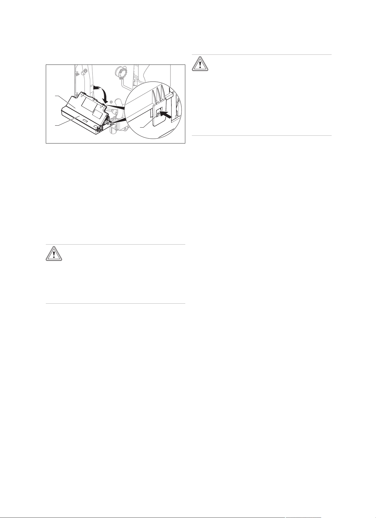
5.4.1 Opening/closing the electronics box
5.4.1.1 Opening the electronics box
1. Remove the front casing. (→ Page 10)
2. Hinge the electronics box (1) forward.
3. Undo the clips (3) from the brackets.
4. Hinge up the cover (2).
5.4.1.2 Closing the electronics box
1. Close the cover (2) by pushing downwards on the electronics box (1).
2. Ensure that all the clips (3) audibly click into the brackets.
3. Hinge the electronics box upwards.
5.4.2 Establishing the power supply
Caution.
Risk of material damage due to high con-
nected voltage.
At mains voltages greater than 253 V, electronic components may be damaged.
▶ Ensure that the nominal voltage of the
mains is 230 V (+10%/-15%) ~ 50 Hz.
5.4.3 Carrying out the wiring
Caution.
Risk of material damage caused by incor-
rect installation.
Mains voltage at the incorrect plug terminals
on the ProE system may destroy the electronics.
▶ Do not connect any mains voltage to the
eBUS terminals (+/-).
▶ Only connect the power supply cable to
the terminals marked for the purpose.
1. Route the supply lines of the components to be connected through the cable duct provided on the underside of
the product.
2. Use the strain reliefs provided.
3. Shorten the supply lines as necessary.
4. To prevent short circuits if a strand accidentally comes
loose, only strip the outer sheathing of flexible lines to a
maximum of 30 mm.
5. Ensure the inner conductor insulation is not damaged
when stripping the outer sheathing.
6. Only strip inner conductors just enough to establish
good, sound connections.
7. To avoid short circuits resulting from loose individual
wires, fit conductor end sleeves on the stripped ends of
the conductors.
8. Screw the respective ProE plug to the supply line.
9. Check whether all conductors are sitting mechanically
securely in the terminals of the ProE plug. Remedy this
if necessary.
10. Plug the ProE plug into the associated PCB slot.
11. Secure the cable in the electronics box using the strain
reliefs.
1. Observe all valid regulations.
2. Open the electronics box. (→ Page 16)
3. Provide one common electricity supply for the boiler
and for the corresponding controller:
– Power supply: Single-phase, 230 V, 50 Hz
– Fuse protection: ≤ 3 A
4. Connect the product using a fixed connection and a
partition with a contact opening of at least 3 mm (e.g.
fuses or power switches).
5. Use a flexible line for the mains feed line, which is
routed through the cable duct into the product.
6. Carry out the wiring. (→ Page 16)
7. Observe the connection diagram (→ Page 45).
8. Screw the supplied ProE plug to a suitable, flexible
three-core mains connection cable which complies with
the relevant standards.
9. Close the electronics box. (→ Page 16)
10. Make sure that access to the mains connection is al-
ways available and is not covered or blocked.
16 Installation and maintenance instructions ecoTEC plus 0020134823_07
Page 17
Installation 5
X18
230 V
X22
5.4.4 Connecting the pump group
1. Open the electronics box. (→ Page 16)
2. Carry out the wiring. (→ Page 16)
3. Use the strain reliefs provided.
4. Plug the ProE plug for the power supply cable into slot
X18.
5. Plug the ProE plug for the control cable into slot X22.
6. Close the electronics box. (→ Page 16)
5.4.5 Installing the control
▶ Install the control if necessary.
5.4.6 Connecting controls to the electronics
1. Open the electronics box. (→ Page 16)
2. Carry out the wiring. (→ Page 16)
3. If you connect a weather-compensated control or room
thermostat to the product via eBUS, bridge the input
24 V = RT (X100 or X106) if no bridge exists.
4. If you use a low-voltage control (24 V), connect this
instead of the bridge 24 V = RT (X100 or X106).
5. When connecting a limit thermostat (surface-mounted
thermostat) for underfloor heating, connect this instead
of the bridge (Burner off) at the ProE plug.
6. Close the electronics box. (→ Page 16)
Note
Due to the installed system separation, leave
the pump in the factory setting: Comfort
D.018
– Circulation pump
– External pump
– Cylinder charging pump
– Extraction hood
– External solenoid valve
– External fault signal
– Solar pump (not active)
– eBUS remote control (not active)
– Anti-legionella pump (not active)
– Solar valve (not active).
5.4.7.1 Using the VR 40 (2 in 7 multi-functional module)
1. Install the components in accordance with the respect-
ive instructions.
2. Select D.027 (→ Page 25) to actuate relay 1 on the
multi-functional module.
3. Select D.028 (→ Page 25) to actuate relay 2 on the
multi-functional module.
5.4.7.2 Using the flue non-return flap
For cascade operation, you must provide a flue non-return
flap for each product. Either use only electrical flue non-return flaps or use only mechanical flue non-return flaps for all
products in a cascade.
The electrical flue non-return flap is actuated by the VR 40
multi-functional module. The installation instructions for the
VR 40 describe how the flue non-return flap is activated. The
mechanical flue non-return flap has an integrated siphon,
which must be filled with water before starting up the unit.
You can omit the flue non-return flap if you can ensure that
the flue system is operated completely under negative pressure.
Condition: Operating with natural gas
▶ For smooth operation with natural gas and a flue non-re-
turn flap, use diagnostics code D.050 (→ Page 25) to increase the offset for the minimum fan speed to the fixed
value of 1500 rpm.
Condition: Operating with liquefied petroleum gas
▶ You must never raise the speed under D.050
(→ Page 25) any higher because a higher speed is
already being used when operating with liquid gas.
5.4.8 Actuating the circulation pump according to requirements
1. Connect the wiring in the same way as described
in "Connecting controllers to the electronic system
(→ Page 17)".
2. Connect the supply line for the external button using
terminals 1 (0) and 6 (functional drawing) on the X41
edge connector, which is supplied with the controller.
3. Plug the edge connector into the PCB slot X41.
5.4.7 Connecting additional components
You can use the multi-functional module to actuate two additional components.
The following components can be actuated:
0020134823_07 ecoTEC plus Installation and maintenance instructions 17
Page 18
6 Operation
6 Operation
6.1 Operating concept of the product
The operating concept and the read-out and setting options
of the end user level are described in the operating instructions.
An overview of the read-out and setting options of the installer level can be found in the section "Overview of the
menu structure – Installer level" (→ Page 37).
6.1.1 Calling up the installer level
Caution.
Risk of material damage caused by incor-
rect handling.
Incorrect settings at installer level may cause
damage and operating faults to the heating
installation.
▶ You must only access the installer level if
you are an approved competent person.
Note
The installer level is protected against unauthorised access using a password.
1. Press and ("i") simultaneously.
◁ The following menu appears in the display.
2. Scroll using the or button, until the menu item
Installer level appears.
3. Press (OK) to confirm your selection.
◁ In the display, the text Enter code appears along
with the value 00.
4. Use or to set the value 17 (code).
5. Press (OK) to confirm your selection.
◁ The installer level appears with a selection of menu
items.
6.2 Live Monitor (status codes)
7 Start-up
7.1 Auxiliary service equipment
The following test and measuring equipment is required for
start-up:
– CO2analyser
– Digital or U-tube manometer
– Flat-blade screwdriver, small
– 2.5 mm hex key
7.2 Carrying out the initial start-up
Note
The complete heating system must be flushed
at least twice: Once with cold water and once
with domestic hot water in accordance with the
following instructions (→ section "Flushing the
heating installation for the first time")
Initial start-up must be carried out by a customer service
technician or an authorised competent person using the firstcommissioning-checklist and the commissioning checklist.
The first-commissioning-checklist and the commissioning
checklist (→ Page 49) in the appendix for the installation instructions must be filled out and stored carefully along with
the product documentation.
Initial start-up checklist (→ Page 46)
▶ Carry out the initial start-up using the checklist and the
commissioning checklist in the appendix.
▶ Fill out and sign the checklists.
7.3 Checking and treating the heating water/filling and supplementary water
Caution.
Risk of material damage due to poor-qual-
ity heating water
▶ Ensure that the heating water is of suffi-
cient quality.
Menu → Live Monitor
Status codes in the display provide information on the product's current operating status.
Status codes – Overview (→ Page 42)
6.3 Test programmes
As well as the installation assistants, you can also call up the
test programmes for start-up, maintenance and troubleshooting.
Menu → Installer level Test programmes
There you will find the Check programmes (→ Page 20),
in addition to the Function menu, an Electronics self-test
and the Gas family check.
▶ Before filling or topping up the installation, check the
quality of the heating water.
Checking the quality of the heating water
▶ Remove a little water from the heating circuit.
▶
Check the appearance of the heating water.
▶ If you ascertain that it contains sedimentary materials,
you must desludge the installation.
▶ Use a magnetic rod to check whether it contains mag-
netite (iron oxide).
▶ If you ascertain that it contains magnetite, clean the in-
stallation and apply suitable corrosion-protection measures, or fit a magnet filter.
▶ Check the pH value of the removed water at 25 °C.
▶ If the value is below 8.2 or above 10.0, clean the installa-
tion and treat the heating water.
▶
Ensure that oxygen cannot get into the heating water.
Checking the filling and supplementary water
▶ Before filling the installation, measure the hardness of the
filling and supplementary water.
18 Installation and maintenance instructions ecoTEC plus 0020134823_07
Page 19

Start-up 7
Treating the filling and supplementary water
▶ Observe all applicable national regulations and technical
standards when treating the filling and supplementary
water.
Provided the national regulations and technical standards
do not stipulate more stringent requirements, the following
applies:
You must treat the heating water in the following cases:
– If the entire filling and supplementary water quantity dur-
ing the operating life of the system exceeds three times
the nominal volume of the heating installation, or
– If the values shown in the curve ( Appendix) have been
exceeded, or
– If the pH value of the heating water is less than 8.2 or
more than 10.0.
Caution.
Risk of material damage if the heating
water is treated with unsuitable additives.
Unsuitable additives may cause changes in
the components, noises in heating mode and
possibly subsequent damage.
▶ Do not use any unsuitable frost and cor-
rosion protection agents, biocides or sealants.
No incompatibility with our products has been detected to
date with proper use of the following additives.
▶ When using additives, follow the manufacturer's instruc-
tions without exception.
We accept no liability for the compatibility of any additive or
its effectiveness in the rest of the heating system.
Additives for cleaning measures (subsequent
flushing required)
– Adey MC3+
– Adey MC5
– Fernox F3
– Sentinel X 300
– Sentinel X 400
Additives intended to remain permanently in the
installation
– Adey MC1+
– Fernox F1
– Fernox F2
– Sentinel X 100
– Sentinel X 200
Additives for frost protection intended to remain
permanently in the installation
– Adey MC ZERO
– Fernox Antifreeze Alphi 11
– Sentinel X 500
▶ If you have used the above-mentioned additives, inform
the end user about the measures that are required.
▶ Inform the end user about the measures required for frost
protection.
7.4 Switching on the product
▶ Press the on/off button on the product.
◁ The basic display appears on the display.
7.5 Running the installation assistants
The installation assistant is displayed whenever the product
is switched on until it has been successfully completed.
It provides direct access to the most important check
programmes and configuration settings for starting up the
product.
Confirm the launch of the installation assistant. All heating
and domestic hot water demands are blocked whilst the installation assistant is active.
Confirm that you want to navigate to the next point by pressing Next.
If you do not confirm the launch of the installation assistant,
it is closed 10 seconds after you switch on the unit and the
basic display then appears.
7.5.1 Language
▶ Set the required language.
▶ Press (OK) twice to confirm the set language and to
avoid unintentionally changing it.
If you have unintentionally set a language that you do not
understand, proceed as follows to change it:
▶ Simultaneously press and hold and .
▶ Also press the fault clearance key for a short time.
▶ Press and hold and until the display shows the
language setting option.
▶ Select the required language.
▶ Confirm this change by pressing (OK) twice.
7.5.2 Filling mode
Filling mode (check programme P.06) is activated automatically in the installation assistant for as long as the filling mode
appears on the display.
7.5.3 Purging
1. Unlike in the check programmes menu, to purge the
system, start up the check programme P.00 by pressing
or .
2. If you need to change the circuit that is being purged,
press .
7.5.4 Target feed temperature, hot water
temperature, Comfort mode
1. To set the target feed temperature, hot water temperature and Comfort mode, use the and buttons.
2. Confirm the setting by pressing (OK).
7.5.5 Partial heat load
The partial heat load of the product is set to Auto at the factory. This means that the product independently determines
the optimum heating output depending on the current heat
demand of the installation. The setting can also be changed
at a later point using D.000.
0020134823_07 ecoTEC plus Installation and maintenance instructions 19
Page 20

7 Start-up
P.00 Purging
Cancel
Heating circuit
1,2 bar
7.5.6 Additional relay and multi-functional module
Additional components that are connected to the product can
be adjusted here. This setting can be changed using D.027
and D.028.
7.5.7 Competent person telephone number
You can store your telephone number in the unit menu. The
end user can view the telephone number. The telephone
number can be up to 16 digits long and must not contain any
spaces.
7.5.8 Ending the installation assistant
Once the installation assistant has been completed and confirmed, it will not start up automatically next time the unit is
switched on.
7.6 Restarting the installation assistants
You can restart the installation assistant at any time by calling it up in the menu.
Menu → Installer level → Start inst. assistant
7.7 Calling up unit configuration and diagnostics menu
To recheck and reset the most important system parameters,
call up the Unit configuration.
Menu → Installer level Unit configuration
The setting options for more complex installations can be
found in the Diagnostics menu.
Menu → Installer level Diagnostics menu
7.8 Using check programmes
Menu → Installer level → Test programmes → Check programmes
By activating various check programmes, you can trigger
special functions on the product.
Note
If the product is in error condition, you cannot start
any check programmes. You can detect an error
condition by the fault symbol shown in the left
bottom corner of the display. You must first reset.
To terminate the check programmes, you can press (Can-
cel) at any time.
7.9 Reading off the filling pressure
The product's supply pipe is equipped with an analogue
pressure gauge, a symbolic bar graph display and a digital
pressure gauge.
▶ To read off the digital filling pressure value, press the
button twice.
If the heating installation is full, in order to ensure that it operates smoothly, the indicator on the pressure gauge must
point to the upper half of the grey area or to the middle of the
bar graph display on the display (marked by the dashed limit
values) when the heating installation is cold. This corresponds to a filling pressure of between 0.1 MPa and 0.2 MPa
(1.0 bar and 2.0 bar).
If the heating installation extends over several storeys,
higher filling pressures may be required to avoid air entering
the heating installation.
7.10 Preventing low water pressure
Display Meaning
P.00 Purging check programme:
P.01 Maximum load check programme:
P.02 Minimum load check programme:
P.06 Filling mode check programme:
The boiler circulation pump is cyclically actuated.
The heating circuit is purged via the automatic air
vent.
1 x : Start heating circuit purging
3 x ( ): Restart heating circuit purging
1 x (Cancel): End purge programme
Note
The purge programme runs for 7.5 min per circuit
and then terminates.
Purging the heating circuit:
Actuating the external pump for 15 cycles: 15 s on,
10 s off. Display: Active heating circuit.
After successful ignition, the product is operated at
maximum heat input.
After successful ignition, the product is operated at
minimum heat input.
The burner and pump are switched off (to fill or drain
the product).
To prevent damage to the boiler that is caused by a filling
pressure that is too low, the boiler is fitted with a water
pressure sensor. If the filling pressure falls below 0.1 MPa
(1.0 bar), the product indicates low pressure by displaying a
flashing pressure value. If the filling pressure falls below 0.05
MPa (0.5 bar), the product switches off. The display shows
F.22.
▶ Top up the heating water to start the product up again.
The pressure value flashes in the display until a pressure of
0.11 MPa (1.1 bar) or higher has been reached.
▶ If you notice frequent drops in pressure, determine and
eliminate the cause.
20 Installation and maintenance instructions ecoTEC plus 0020134823_07
Page 21

Start-up 7
2
1
7.11 Flushing the heating system for the first time
("cold")
Note
Establish suitable connections for correctly filling
the boiler circuit and use a suitable filling device.
Due to the system separation, separate connections are required for the installation circuit.
1. Check that all thermostatic radiator valves and both
service valves on the boiler are open.
2. Select the check programme P.06.
◁ The pumps do not run and the product does not
enter heating mode.
3. Open the filling water supply.
4. Slowly fill the boiler and the heating installation.
5. Open all available purging valves in the heating system.
Note
The boiler is equipped with an automatic
air vent. Other measures need to be taken
to allow the heating system to be purged
during filling and during commissioning either
manually or using an automatic air vent.
6. Connect a hose to the drain valve that is located at the
lowest position in the heating system.
7. Connect a hose to the boiler's drain valve.
8. Open these two drain valves so that the water can drain
quickly. Start at the next point in the installation and
open the purging valves on the radiators so that the
contaminated water can completely drain.
9. Close the drain cocks.
– Minimum filling pressure: 0.1 MPa (1.0 bar)
Note
The check programme P.00 runs for
7.5 minutes per circuit.
At the end of the filling process, the filling
pressure should be at least 0.02 MPa
(0.2 bar) above the counter-pressure of the
expansion vessel ("Exp") (P
0.02 MPa (0.2 bar)).
10. If there is still too much air in the boiler at the end of the
check programme P.00, restart the check programme.
11. Check all connections and the entire system for leaktightness (→ Page 24).
12. Check the expansion relief valve by opening it briefly.
Installation
≥ P
Exp
+
◁ Water escapes from the expansion relief valve.
13. Complete and sign off the Benchmark commissioning
check list and then register the guarantee.
7.13 Filling the condensate trap
Danger!
Risk of poisoning due to escaping flue
gas.
An empty or insufficiently filled condensate
trap may allow flue gas to escape into the
room air.
▶ Fill the condensate trap with water before
starting up the product.
7.12 Filling and purging the heating system
Condition: The heating installation and the boiler have been rinsed thor-
oughly.
▶ Select the check programme P.06.
◁ The pumps do not run and the product does not
enter heating mode.
1. Proceed in accordance with the information provided on
treating (→ Page 18) heating water and on the topic of
water hardness (→ Page 54).
2. Open the filling water supply.
3. Check that both service valves on the boiler are open.
4. Slowly fill the boiler.
5. Observe the increasing filling pressure in the boiler.
6. Fill with water until the required filling pressure is
reached.
7. Close off the filling system but keep ready to top up as
air is expelled during the purging process.
8. To purge the boiler, select check programme P.00.
◁ The boiler does not start up, the external pump op-
erates intermittently and purges either the heating
circuit or the domestic hot water circuit. The display
shows the boiler's filling pressure.
9. To be able to carry out the purging process properly,
the filling pressure must not fall below the minimum
filling pressure.
1. Remove the lower section of the condensate trap
unscrewing it from the condensate trap (1).
2. Fill the lower section of the condensate trap with water
up to about 10 mm below the upper edge.
3. Secure the lower section of the condensate trap correctly to the condensate trap again.
(2) by
0020134823_07 ecoTEC plus Installation and maintenance instructions 21
Page 22

7 Start-up
1
7.14 Checking and adjusting the gas setting
7.14.1 Checking the factory setting
Caution.
An incorrect gas group setting may cause
operating faults or a reduction in the service life of the product.
If the product design does not match the local
gas group, malfunctions will occur or you will
have to replace product components prematurely.
▶ Before you start up the product, compare
the gas group information on the data
plate with the gas group available at the
installation site.
The product's combustion has been factory tested and is
preset for operation with the gas group indicated on the data
plate.
Condition: The product design is not compatible with the local gas group
If you want to operate the product with liquefied petroleum
gas, do not start up the product.
A gas conversion must only be carried out by Vaillant customer service or the manufacturer of the product.
▶
Notify Vaillant customer service or the manufacturer of
the product that you want a gas conversion carried out.
Condition: The product design is compatible with the local gas group
▶ Proceed as described below.
7.14.2 Checking the leak-tightness of the flue gas system and for flue gas recirculation
1. Check the flue gas installation is intact in accordance
with the latest gas safe technical bulletin and information supplied in the installation instructions.
2. For extended flue gas installations check for flue gas
recirculation using the air analysis point.
7. Check again whether the supply air contains any CO or
CO2.
8. If you cannot eliminate the damage, do not start up the
product.
7.14.3 Checking the gas flow rate
The boiler is fitted with a multifunctional automatic gas valve
which ensures that the precise air/gas ratio is provided under
all operating conditions.
The gas flow rate has been set during production and does
not require adjustment. With the front casing fitted check the
gas flow rate of the boiler as follows:
▶ Start up the product with the check programme P.01.
▶ Ensure that maximum heat can be dissipated into the
heating system by turning up the room thermostat.
▶ Wait at least 5 minutes until the boiler has reached its
operating temperature.
▶ Ensure that all other gas appliances in the property are
turned off.
▶ Measure the gas flow rate at the gas meter.
▶ Compare the measured values with the corresponding
values in the table.
Qnw from the data
plate
76.2 8.10 8.51 7.29
95.2 10.10 10.61 9.09
114.3 12.10 12.71 10.89
Condition: Gas flow rate not in the permissible range
H gas in m³/h
Nom. +5 % −10 %
▶ Check all of the piping and ensure that the gas flow rates
are correct.
▶ Only put the product into operation once the gas flow
rates have been corrected.
Condition: Gas flow rate in the permissible range
▶ End the check programme P.01.
▶ Allow the boiler to cool down by allowing pump overrun to
operate for a minimum of 2 minutes.
▶ Record the boiler maximum gas flow rate onto the
Benchmark gas boiler commissioning checklist.
3. Use the air analysis point (1) to check for flue gas recirculation.
4. Use a flue gas analyser.
5. If you discover CO or CO2in the supply air, search for
the leak in the flue gas installation or for signs of flue
gas recirculation.
6. Eliminate the damage properly.
22 Installation and maintenance instructions ecoTEC plus 0020134823_07
Page 23

Start-up 7
1
1
806/5-5
1206/5-5
1006/5-5
1
7.14.4 Checking the gas flow pressure
1. Ensure that the gas inlet working pressure can be
obtained with all other gas appliances in the property
working.
2. Close the gas stopcock.
3. Use a screwdriver to undo the sealing screw of the test
nipple (1) at the gas valve assembly.
4. Connect a manometer to the test nipple (1).
5. Open the gas stopcock.
6. Start up the product with the check programme P.01.
7. In addition, ensure that maximum heat can be dissipated into the heating system by turning up the room
thermostat.
8. With the boiler operating at full load check that the gas
inlet working pressure at the reference test point (1)
complies with the requirements.
– Permissible gas flow pressure for operation with
natural gas H: 1.7 to 2.5 kPa (17.0 to 25.0 mbar)
9. Should the pressure recorded at the reference test point
in the boiler be lower than indicated check if there is
any blockage in the pipework or if the pipework is undersized.
▶ Do not make any adjustments to the
product.
▶ Check the gas installation.
▶ Do not start up the product.
▶ If you cannot correct the failure, notify the gas supply
company and proceed as follows:
▶ End the check programme P.01.
▶ Allow the boiler to cool down by allowing pump overrun
to operate for a minimum of two minutes.
▶ Close the gas stopcock.
▶ Remove the pressure gauge and retighten the sealing
screw (1) for the measuring nipple.
▶ Open the gas stopcock.
▶ Check the test nipple for gas tightness.
▶ Close the gas stopcock.
▶ Install the front casing. (→ Page 10)
▶ Disconnect the product from the power grid.
▶ You must not start up the boiler.
Condition: Gas flow pressure in the permissible range
▶ End the check programme P.01.
▶ Allow the boiler to cool down allowing pump overrun to
operate for a minimum of two minutes.
▶ Close the gas stopcock.
▶ Remove the pressure gauge and retighten the sealing
screw (1) for the measuring nipple.
▶ Open the gas stopcock.
▶ Check the test nipple for gas tightness.
▶ Install the front casing. (→ Page 10)
▶ Reset boiler controls for normal operation.
▶ Record the appliance gas inlet working pressure (kPa
resp. mbar) in the Benchmark gas boiler commissioning
checklist.
7.14.5 Checking the CO₂ content and, if necessary,
adjusting it (air index setting)
1. Start up the product with the check programme P.01.
2. Wait at least five minutes until the product reaches its
operating temperature.
Condition: Gas flow pressure not in the permissible range
Caution.
Risk of material damage and operating
faults caused by incorrect gas flow pressure.
3. Measure the CO₂ and CO/CO₂ content at the flue gas
analysis point (1).
4. Compare the measured values with the corresponding
values in the table.
If the gas flow pressure lies outside the permissible range, this can cause operating
faults in and damage to the product.
0020134823_07 ecoTEC plus Installation and maintenance instructions 23
Page 24

7 Start-up
1
1
806/5-5
1006/5-5
1206/5-5
Set values Unit Natural
CO₂ after 5 minutes in full load
mode with front casing closed
CO₂ after 5 minutes in full load
mode with front casing removed
Set for Wobbe index W
O₂ after 5 minutes in full load
mode with front casing closed
CO content ppm ≤ 250
CO/CO2content
Condition: The CO₂ content must be adjusted
s
Vol.–% 9.0 ±1.0
Vol.–% 8.8 ±1.0
kWh/m³ 15.0
Vol.–% 4.89 ±1.80
gas H
0.0028
Note
Turn to the left: Higher CO₂ content
Turn to the right: Lower CO₂ content
▶ Only carry out the adjustment in increments of 1/8 turn
and wait approximately 1 minute after each adjustment
until the value stabilises.
Note
On the VU GB 1006/5-5 and the VU GB
1206/5-5, after changing the direction of
rotation, the CO₂ content only changes
after approx. 1 turn of the adjusting screw
(overcoming the adjustment hysteresis).
The adjusting screw must protrude only
slightly from the casing.
▶ Select (Cancel) once the adjustments have been made.
▶ If an adjustment is not possible in the specified adjust-
ment range, you must not start up the product.
▶ If this is the case, inform Vaillant Customer Service.
▶ Install the front casing. (→ Page 10)
7.15 Checking leak-tightness
Caution.
Risk of poisoning due to an incorrectly
installed gas valve assembly.
If the gas flow pressure is outside the permissible ranges in the table, this may lead to
personal injury and material damage.
▶ Check the integrity of all gas pipes.
▶ Check the flue system for tightness.
▶ Check the gas flow pressure.
▶ Check the gas flow rate.
▶ Break through the sealing sticker.
▶ Set the CO₂ content (value with front casing removed)
by turning the screw (1).
▶ Check the gas pipe, the heating circuit and the hot water
circuit for leak-tightness.
▶ Check that the flue system has been installed correctly.
7.15.1 Checking the heating mode
1. Make sure that there is a heat requirement.
2. Call up the Live Monitor.
– Menu → Live Monitor
◁ If the product is working correctly, the display shows
S.04.
7.15.2 Checking the hot water generation
Danger!
Risk of death from legionella.
Legionella multiply at temperatures below
60 °C.
▶ Ensure that the end user is familiar with
all of the Anti-legionella measures in order
to comply with the applicable regulations
regarding legionella prevention.
Condition: Cylinder connected
▶ Make sure that the cylinder thermostat is requesting
heat.
1. Call up the Live Monitor.
– Menu → Live Monitor
◁ If the cylinder is charged correctly, the display
shows S.24.
2. If you have connected a controller which can be used to
set the hot water temperature, set the hot water temperature on the boiler to the maximum possible temperature.
24 Installation and maintenance instructions ecoTEC plus 0020134823_07
Page 25

Adapting the unit to the heating installation 8
3. Adjust the target temperature for the connected domestic hot water cylinder to the controller.
◁ The boiler adopts the set target temperature which
is set on the controller (automatic calibration in
newer controllers).
4. Set the hot water temperature.
Condition: Water hardness: > 3.57 mol/m³
– Water temperature: ≤ 50 ℃
7.16 Thoroughly flushing the heating system
("hot")
1. Ensure that the water within the boiler is clean and low
in temporary hardness and no system debris can circulate through the boiler during first firing.
2. Keep this firing time short and temperature no higher
than 50°C as this is just to remove contaminates and
not for balancing the system at this time.
3. Operate the boiler until the water is up to temperature
(max 50 °C).
4. Check the heating system for leaks.
5. Connect a hose to the drain valve at the boiler.
6. Shut off the boiler, open the drain valve and all purge
valves and allow the water to flow out of the boiler
quickly and fully.
7. Close the drain valve.
8. Proceed in accordance with the information provided
on treating heating water in "Checking and treating
the heating water/filling and supplementary water"
(→ Page 18).
9. Re-fill the boiler in accordance with "Filling and purging
the heating installation" (→ Page 21).
10. Ensure that the inhibitor levels are correctly maintained
throughout the boilers operational life.
Or manually relaunch the installation assistant.
Menu → Installer level → Start inst. assistant
8.1 Calling up diagnostics codes
The settings options for more complex systems can be found
in the Diagnostics menu.
Menu → Installer level Diagnostics menu
Overview of diagnostics codes (→ Page 39)
Using the parameters that are marked as adjustable in the
overview of diagnostics codes, you can adapt the product to
the heating installation and the needs of the customer.
▶ Press or to change the diagnostics code.
▶ Press (Select) to select the parameter to change.
▶ Press or to change the current setting.
▶ Press (OK) to confirm your selection.
8.2 Setting the partial heat load
The partial heat load of the product is set to Auto at the
factory. If you still want to set a fixed maximum partial heat
load, you can set a value under D.000, which equates to the
product output in kW.
If the product is operated in cascade, you must increase
the offset for the minimum fan speed of the unit to the fixed
value 1500 rpm (D.050) when operating it with natural gas
and you must never raise the speed under D.050 any higher
when operating it with liquefied petroleum gas because a
higher speed is already being used.
If a domestic hot water cylinder (cylinder type VIH) is installed, you can adjust the partial load setting for the cylinder
charging to the cylinder type (D.077).
Note
The actual reading on the digital pressure
gauge should ideally be 0,05 MPa (0,5 bar)
plus an additional pressure corresponding
to the highest point of the system above the
base of the boiler – 10 m head equals an additional 1 bar reading on the pressure gauge.
The minimum pressure should not be less
than 0,1 MPa (1 bar) in any installation. If
the system is to be treated with an inhibitor
it should be applied at this stage in accordance with the manufacturer’s instructions.
Further information can be found regarding
inhibitor treatment in "Checking and treating
the heating water/filling and supplementary
water" (→ Page 18).
11. Install the side section. (→ Page 11)
12. Install the front casing. (
→ Page 10)
8 Adapting the unit to the heating
installation
8.3 Setting the pump overrun
You can set the pump overrun under D.001 (factory setting:
5 min.).
Note
The internal pump's operating mode is set to
Comfort at the factory. The pump is switched on
when the heating flow temperature is not at Heat-
ing off (→ Operating instructions) and the heat
requirement is enabled via an external control.
You must not change the factory setting under
D.018!
8.4 Setting the maximum flow temperature
You can set the maximum flow temperature for the heating
mode under D.071 (default setting: 75 °C).
To reset the most important system parameters, use the
Unit configuration menu item.
Menu → Installer level Unit configuration
0020134823_07 ecoTEC plus Installation and maintenance instructions 25
Page 26

8 Adapting the unit to the heating installation
8.5 Setting the return temperature control system
If the product is connected to an underfloor heating system,
the temperature control can be changed from flow temperature control (factory setting) to return temperature control
under D.017. If you have activated the return temperature
control under D.017, the automatic heating output determination function is not active. If you set D.000 to Auto anyway,
the product operates with the maximum possible partial heat
load.
8.6 Burner anti-cycling time
8.6.1 Setting the burner anti-cycling time
To prevent frequent switching on and off of the burner and
thus prevent energy losses, an electronic restart lockout
is activated for a specific period each time the burner is
switched off. You can adjust the burner anti-cycling time to
the conditions of the heating installation. The burner anticycling time is only active for the heating mode. You can set
the maximum burner anti-cycling time under D.002 (default
setting: 20 min.). The effective burner anti-cycling times with
respect to the target flow temperature and the maximum set
burner anti-cycling time can be found in the following table:
T
Flow
(target)
[°C]
30 2.0 4.0 8.5 12.5 16.5 20.5 25.0
35 2.0 4.0 7.5 11.0 15.0 18.5 22.0
40 2.0 3.5 6.5 10.0 13.0 16.5 19.5
45 2.0 3.0 6.0 8.5 11.5 14.0 17.0
50 2.0 3.0 5.0 7.5 9.5 12.0 14.0
55 2.0 2.5 4.5 6.0 8.0 10.0 11.5
60 2.0 2.0 3.5 5.0 6.0 7.5 9.0
65 2.0 1.5 2.5 3.5 4.5 5.5 6.5
70 2.0 1.5 2.0 2.5 2.5 3.0 3.5
75 2.0 1.0 1.0 1.0 1.0 1.0 1.0
T
Flow
(target)
[°C]
30 29.0 33.0 37.0 41.0 45.0 49.5
35 25.5 29.5 33.0 36.5 40.5 44.0
40 22.5 26.0 29.0 32.0 35.5 38.5
45 19.5 22.5 25.0 27.5 30.5 33.0
50 16.5 18.5 21.0 23.5 25.5 28.0
55 13.5 15.0 17.0 19.0 20.5 22.5
60 10.5 11.5 13.0 14.5 15.5 17.0
65 7.0 8.0 9.0 10.0 11.0 11.5
70 4.0 4.5 5.0 5.5 6.0 6.5
75 1.0 1.0 1.0 1.0 1.0 1.0
Set maximum burner anti-cycling time [min]
1 5 10 15 20 25 30
Set maximum burner anti-cycling time [min]
35 40 45 50 55 60
8.6.2 Resetting the remaining burner anti-cycling time
1st option
Menu → Reset anti-cycling time
The current burner anti-cycling time appears in the display.
▶ Confirm the burner anti-cycling time reset by pressing
(Select).
2nd option
▶ Press the reset button.
8.7 Setting the maintenance interval
If you set the maintenance interval, the message that the
product must be serviced appears in the display, together
with the maintenance symbol , after a configurable number
of burner operating hours. The display on the eBUS control
shows the information Maintenance MAIN.
▶ Set the operating hours until the next maintenance work
is due using D.084. You can set the operating hours in
increments of ten from 0 to 3010 h (hours).
If you do not set a numerical value, but instead set the symbol "–", the "Maintenance display" function is not active.
Note
On completion of the set operating hours, you
must set the maintenance interval again.
8.8 Pump output (high-efficiency pump)
The product can be equipped with a pump group with a highefficiency pump (accessories). The pump is fully modulating
and is actuated according to the heat requirement.
The remaining feed head of this pump group is designed so
that the full heat output is transported as far as the system
separation.
Remaining feed head
The following values apply for a pump speed target value ≥
85%:
Unit output
Circulation water
volume at maximum
heat input (ΔT=23 K)
Water pressure
downstream of the
boiler at maximum
water flow rate, with
non-return valve
Water pressure
downstream of the
boiler at maximum
water flow rate,
without non-return
valve
80 kW 100 kW 120 kW
2.99 m³/h 3.74 m³/h 4.49 m³/h
0.065 MPa
(0.650 bar)
0.073 MPa
(0.730 bar)
0.053 MPa
(0.530 bar)
0.061 MPa
(0.610 bar)
0.042 MPa
(0.420 bar)
0.050 MPa
(0.500 bar)
Note
The remaining burner anti-cycling time following a
regular shutdown in heating mode can be called
up under D.067.
26 Installation and maintenance instructions ecoTEC plus 0020134823_07
Page 27

Adapting the unit to the heating installation 8
A
B
0 1000 2000 3000 4000 5000 6000 7000
100
200
300
400
500
600
700
800
900
1000
1100
1200
1
2 3
100 %
85 %
70 %
60 %
53 %
A
B
100
200
300
400
500
600
700
800
900
1000
1100
1200
0 1000 2000 3000 4000 5000 6000 7000 8000
1
2 3
100 %
85 %
70 %
60 %
53 %
80 kW boiler with high-efficiency pump
100 kW boiler with high-efficiency pump
1 Circulation water
volume at minimum
heat input
2 Circulation water
volume at maximum
heat input (ΔT=23 K)
3 Circulation water
volume at maximum
heat input (ΔT=20 K)
A Circulation water
volume [l/h]
B Remaining feed head
[mbar]
1 Circulation water
volume at minimum
heat input
2 Circulation water
volume at maximum
heat input (ΔT=23 K)
3 Circulation water
volume at maximum
heat input (ΔT=20 K)
A Circulation water
volume [l/h]
B Remaining feed head
[mbar]
0020134823_07 ecoTEC plus Installation and maintenance instructions 27
Page 28

9 Inspection and maintenance
A
B
0 1000 2000 3000 4000 5000 6000 7000 8000
100
200
300
400
500
600
700
800
900
1000
1100
1
2 3
100 %
85 %
70 %
60 %
53 %
120 kW boiler with high-efficiency pump
9 Inspection and maintenance
Auxiliary service equipment:
You require the following tool for the inspection and maintenance:
– WAF 8 socket spanner with extension
– Torx screwdriver 20, 25 and 30
– 5 mm hex key
▶ Carry out all inspection and maintenance work in the
order shown in the table "Overview of inspection and
maintenance work".
9.1 Observing inspection and maintenance intervals
Warning.
Risk of injury and a risk of material dam-
age caused by negligent inspection and
maintenance work.
Negligence in inspection and maintenance
work, as well as failure to comply with the
specified inspection and maintenance intervals, may impair the operational safety of
the product and lead to injuries and material
damage.
▶ Instruct the end user that the prescribed
inspection and maintenance intervals
must be complied with as a minimum requirement.
▶ Carry out a regular inspection once a
year.
1 Circulation water
volume at minimum
heat input
2 Circulation water
volume at maximum
heat input (ΔT=23 K)
8.9 Handing the product over to the end user
1. When you have finished the installation, attach the
sticker supplied (835593) to the front of the product in
the user's language.
2. Explain to the end user how the safety devices work
and where they are located.
3. Inform the end user how to handle the product. Answer
4. Inform the end user that they must have the product
5. Pass all of the instructions and documentation for the
6. Inform the end user about measures taken to ensure
any questions the end user may have. In particular,
draw attention to the safety warnings which the end
user must follow.
maintained in accordance with the specified intervals.
product to the end user for safe-keeping.
the combustion air supply and flue system, and instruct
the end user that he must not make any changes.
3 Circulation water
volume at maximum
heat input (ΔT=20 K)
A Circulation water
volume [l/h]
B Remaining feed head
[mbar]
Any customer service work must be carried out by a professionally qualified person in accordance with the safety, installation and operating provisions for gas-fired units. Professional qualification must be confirmed by an adequately
recognised organisation or public office.
▶ Carry out regular maintenance work in line
with the findings from the inspection. The
maintenance interval must not be longer
than two years.
Warning.
Risk of injury and death due to improper
inspection and maintenance!
Improper performance of inspections and
maintenance work may result in leaks or
even an explosion.
▶ Inspection and maintenance work on the
product must only be carried out by professionally qualified persons.
28 Installation and maintenance instructions ecoTEC plus 0020134823_07
Page 29

Inspection and maintenance 9
2
1
Note
The person who carries out a combustion measurement must be trained in the use of a flue gas
measuring instrument and in interpreting the results. The flue gas measuring instrument that is
used must be calibrated in accordance with the
specifications of the measuring instrument manufacturer. The correct fuel type must be set on the
flue gas measuring instrument.
Inspection
The inspection is intended to determine the actual condition
of the product and compare it with the target condition. This
is done by measuring, checking and observing.
Maintenance
Maintenance is required in order to eliminate any deviations
of the actual condition from the target condition. This is normally done by cleaning, setting and, if necessary, replacing
individual components that are subject to wear.
As the competent person, you determine the maintenance
intervals (at least once every two years) and their scope
based on the how you define the condition of the product
during the inspection. Carry out all inspection and maintenance work in the sequence shown in Appendix C.
9.2 Procuring spare parts
The original components of the product were also certified
by the manufacturer as part of the declaration of conformity.
If you use other, non-certified or unauthorised parts during
maintenance or repair work, this may void the conformity of
the product and it will therefore no longer comply with the
applicable standards.
We strongly recommend that you use original spare parts
from the manufacturer as this guarantees fault-free and safe
operation of the product. To receive information about the
available original spare parts, contact the contact address
provided on the back page of these instructions.
▶ If you require spare parts for maintenance or repair
work, use only the spare parts that are permitted for the
product.
Display
T.06 Check external
T.08 Checking the
Test
programme
pump
burner
Action
Switch the external pump on
and off.
The product starts up and
switches to minimum load.
The flow temperature is
shown in the display.
Terminate function menu
▶ To terminate the function menu, select (Cancel).
9.4 Carrying out electronics self-tests
Menu → Installer level → Test programmes → Electronics
self-test
You can use the electronics self-test to check the PCB in
advance.
9.5 Removing the gas-air mixture unit
Note
The gas-air mixture unit consists of four main
components:
– Speed-regulated fan,
– Air intake pipe,
– Gas valve assembly,
– Burner
1. Switch off the product using the on/off button.
2. Disconnect the product from the power grid.
3. Close the gas stopcock.
4. Remove the front casing. (→ Page 10)
5. Remove the upper casing. (→ Page 10)
Condition: Applies for 80 kW
9.3 Using the function menu
The function menu allows you to actuate and test individual
components in the heating installation.
Menu → Installer level → Test programmes → Function
menu
▶ Choose the heating installation components.
▶ Press (Select) to confirm your selection.
Display
T.01 Check boiler
T.03 Check fan Switch the fan on and off.
T.04 Check cylinder
T.05 Check circulation
0020134823_07 ecoTEC plus Installation and maintenance instructions 29
Test
programme
circulation pump
charging pump
pump
Action
Switch the boiler circulation
pump on and off.
The fan runs at maximum
rotational speed.
Switch the cylinder charging
pump on and off.
Switch the circulation pump
on and off.
▶ Undo the clip (1) on the air intake pipe (2). and remove
the air intake pipe from the intake stub.
Page 30

9 Inspection and maintenance
3
4
3
4
8
9
10
11
13
5
6
7
12
11
8
10
12
5
6
7
9
13
806/5-5
1006/5-5
1206/5-5
▶ Undo the four screws on the flange connection (3) to the
gas valve assembly.
Condition: Applies for 100 kW and 120 kW
Danger!
▶ Undo the four screws on the flange connection (3) to the
gas valve assembly.
6. Move the gas pipe (4) to the side.
Risk of poisoning and fire caused by escaping gas!
The gas pipe may become damaged.
▶ Ensure that you do not damage the seals
7. Remove the ionisation line plug from the ionisation electrode (11), and remove the earth connection plug from
the earthing lug.
8. Remove the ignition line plug and the earth connection for the ignition electrode (9) from the ignition transformer.
on the gas pipe when removing and installing the gas-air mixture unit.
Note
30 Installation and maintenance instructions ecoTEC plus 0020134823_07
The cable is firmly connected to the ignition
electrode.
Page 31

Inspection and maintenance 9
1
1
4
3
2
1
9. Remove the plugs (12) and (13) from the fan motor by
pushing in the latching lug.
10. Remove the plug from the gas valve assembly (10).
11. Remove the plug from the upper safety cut-out (8).
12. Undo the screws (6) on the burner door.
13. Remove the complete gas-air mixture unit (5) from the
heat exchanger (7).
14. Check the burner and the heat exchanger for damage
and dirt.
9.6 Cleaning the heat exchanger
1. Protect the electronics box against sprayed water.
2. Remove the lower section of the condensate trap to
ensure that any existing condensate neutraliser does
not become damaged.
3. Rinse away any loose dirt in the heat exchanger (1)
with a sharp jet of water or use a plastic brush.
◁ The water flows out of the heat exchanger through
the drain.
4. Install the condensate trap.
9.7 Checking the burner
1. Check the surface of the burner for damage. If you notice any damage, replace the burner, including the seal
(→ Page 35).
2. Check the insulating mat (2) on the burner door. If you
notice any signs of damage, replace the insulating mat
(→ Page 35).
9.8 Replacing the ignition and ionisation
electrodes
Caution.
Risk of material damage caused by dam-
age to the ignition and ionisation electrodes.
The electrodes may become damaged during
installation.
▶ Install the new electrodes only after first
installing the gas-air mixture unit.
0020134823_07 ecoTEC plus Installation and maintenance instructions 31
Page 32

9 Inspection and maintenance
2
1
8
9
10
11
13
5
6
7
12
11
8
10
12
5
6
7
9
13
806/5-5
1006/5-5
1206/5-5
4
4
1. Remove the electrodes (1) from the burner door from
above.
2. Insert the new electrodes with new seals.
– Torque: 2.8 Nm
9.9 Cleaning the condensate trap
1. Remove the lower section of the condensate trap(2) by
unscrewing it from the condensate trap (1).
2. Flush out the lower section of the condensate trap with
water.
3. Fill the lower section of the condensate trap with water
up to about 10 mm below the upper edge.
4. Secure the lower section of the condensate trap to the
condensate trap again.
9.10 Installing the gas-air mixture unit
1. Replace the seal in the burner door.
2. Ensure that the bracket for the insulating mat is
installed properly again after it is replaced.
3. Replace all seals at the sealing points opened during
the maintenance work.
4. Connect the gas-air mixture unit (5) to the heat exchanger (7).
5. Tighten the screws (6) in a cross-wise pattern until the
burner door fits closely and uniformly onto the mating
surfaces.
– Torque: 10 Nm
6. Connect the ignition line plug and the earth connection
for the ignition electrodes (9) to the ignition transformer.
7. Connect the ionisation line plug to the ionisation electrode (11) and connect the earth connection plug to the
earthing lug.
8. Connect the safety cut-out plug to the upper safety cutout (8).
9. Connect the plugs (12) and (13) to the fan motor.
10. Connect the plug (10) to the gas valve assembly.
11. Connect the gas pipe (4) with a new seal to the gas
valve assembly.
32 Installation and maintenance instructions ecoTEC plus 0020134823_07
Page 33

Troubleshooting 10
2
1
Condition: Applies for 80 kW
– Torque: 2 Nm
Condition: Applies for 100 kW and 120 kW
– Torque: 2.8 Nm
Warning.
Risk of poisoning and fire caused by es-
caping gas!
Gas can escape through leaks.
▶ Check the gas tightness at the gas con-
nection using leak detection spray.
12. Open the gas stopcock on the product.
Condition: Applies for 80 kW
10.1 Contacting your service partner
If you contact your Vaillant service partner, if possible,
please mention
– the fault code that is displayed (F.xx),
– the product status (S.xx) that is displayed on the Live
Monitor (→ Page 18).
10.2 Calling up service messages
If the maintenance symbol appears in the display, there is
a service message.
The maintenance symbol appears if you have set a maintenance interval, for example, and it has elapsed. The product is
not in fault mode.
▶ To obtain more information about the service message,
call up the Live monitor (→ Page 18).
Condition: S.44-S.48 is displayed
The product is in Comfort protection mode. The product continues to run with restricted comfort after it has detected a
fault.
▶ To establish whether or not a component is defective,
read the fault memory (→ Page 33).
▶ Check that the sealing ring in the air intake pipe (2) is
positioned correctly in the seal seat.
▶ Reconnect the air intake pipe to the intake stub.
▶
Secure the air intake pipe with the clip (1) on the intake
stub.
13. Close the electronics box.
14. Install the front casing. (→ Page 10)
15. Re-establish the connection to the power grid.
9.11 Draining the product
1. Switch off the product using the on/off button.
2. Close the service valves of the product.
3. Start the check programme P.06.
4. Open the drain valves.
5. Check the water for clouding and additives and correct
this if required.
9.12 Completing inspection and maintenance
work
Once you have completed all maintenance work:
▶ Check the gas flow pressure. (→ Page 23)
▶ Check the CO₂ content and, if necessary, adjust it (air
index setting). (→ Page 23)
10 Troubleshooting
Note
If no fault message is present, the product will
automatically switch back to normal operating
mode after a certain time.
10.3 Reading off the fault codes
If a fault develops in the product, the display shows a fault
code F.xx.
Fault codes have priority over all other displays.
If multiple faults occur at the same time, the display shows
the corresponding fault codes for two seconds each in sequence.
▶ Rectify the fault.
▶ To restart the product, press the fault clearance key (
Operating instructions).
▶ If you are unable to remedy the fault and the fault recurs
despite several fault clearance attempts, contact Vaillant
Service.
10.4 Querying the fault memory
Menu → Installer level Fault list
The product has a fault memory. You can use this to query
the last ten faults that occurred in chronological order.
The display shows:
– The number of faults that have occurred
– The fault currently selected with fault number F.xx
– A plain text display explaining the fault.
▶ You can display the last ten faults that have occurred by
pressing or .
You can find an overview of the fault codes in the appendix.
Overview of fault codes (→ Page 43)
0020134823_07 ecoTEC plus Installation and maintenance instructions 33
Page 34

10 Troubleshooting
2
2
806/5-5
1006/5-5
1206/5-5
1
1
Overview of fault codes (→ Page 43)
10.5 Resetting the fault memory
▶ To delete the entire fault list, press (Delete, OK)
twice.
10.6 Performing diagnostics
▶ You can use the function menu (→ Page 29) to actuate
and test individual components of the product in the fault
diagnostics.
10.7 Using check programmes
You can also use check programmes (→ Page 20) for
troubleshooting.
10.8 Resetting parameters to factory settings
▶ To reset all parameters simultaneously to the default
settings, set D.096 to 1.
10.9 Preparing the repair work
1. Decommission the product.
2. Disconnect the product from the power mains.
3. Remove the front casing.
4. Close the gas isolator cock.
5. Close the service valves in the heating flow and in the
heating return.
6. Close the service valve in the cold water pipe.
7. Drain the product if you want to replace water-bearing
components of the product.
8. Make sure that water does not drip on live components
(e.g. the electronics box).
9. Use only new seals.
10.10 Replacing defective components
10.10.1 Replacing the gas valve assembly
1. Remove the gas pipe (1) from the gas valve assembly.
2. Unscrew the screws (2) from the fan and remove the
gas valve assembly from the fan.
3. Replace the defective component.
4. Install the gas valve assembly and the fan in the same
position as before. Use new seals for this.
5. Tighten the screws (2) in a cross-wise pattern.
Condition: Applies for 80 kW
– Torque: 5.5 Nm
Condition: Applies for 100 kW and 120 kW
6. First, screw the gas pipe loosely onto the gas valve
– Torque: 2 Nm
assembly. Only after completing the installation work
should you tighten the screws for the flange fastening
on the gas valve assembly.
34 Installation and maintenance instructions ecoTEC plus 0020134823_07
Page 35

Troubleshooting 10
1
4
3
2
1
7. After installing the new gas valve assembly, carry out a
leak-tightness test (→ Page 24), and set the gas setting
(→ Page 22).
10.10.2 Replacing the burner
– Torque: 2.8 Nm
12. Install the gas-air mixture unit. (→ Page 32)
13. Check that the product functions correctly and check
the leak-tightness (→ Page 24).
10.10.3 Replacing the insulating mat
If the safety cut-out on the burner door has been triggered,
the insulating mat between the burner door and burner room
may be damaged.
▶ Check and replace the insulating mat.
Note
To replace the insulating mat, proceed in the
same way as when removing the burner. It is
not necessary to remove the burner.
10.10.4 Replacing the fan
1. Remove the gas-air mixture unit. (
→ Page 29)
1. Remove the gas-air mixture unit. (→ Page 29)
2. Remove the ignition and monitoring electrode.
3. Remove the seal (4) from the burner door.
4. Undo the four nuts (1) that are used to secure the insulating mat.
5. Remove the insulating mat (2).
6. Undo the nuts (3) on the burner.
Note
Use a suitable socket spanner (with extension) to ensure that the burner mat does not
become damaged. You must not use burners
that have a damaged mat.
7. Remove the burner. When doing so, hold the fan and
the burner door securely.
8. Fit the new burner with a new seal.
9. Use all of the nuts and washers (3) to secure the
burner.
– Torque: 4 Nm
10. Use four nuts (1) to secure the insulating mat. Ensure
that the insulating mat is touching the burner door and
the cut-outs for the insulating mat lie above the cut-outs
for the burner door.
– Torque: 6 Nm
11. Install the ignition and monitoring electrodes. Use new
seals for this.
2. Undo the four nuts (1) on the fan.
3. Install the new fan on the burner door in the same orientation in which it was previously positioned.
Condition: Applies for 80 kW and 100 kW
– Torque: 3.5 Nm
Condition: Applies for 120 kW
– Torque: 6 Nm
Note
Tighten the screws on the fan evenly. The
fan must not be at an angle.
10.10.5 Replacing the heat exchanger
1. Drain the product. (→ Page 33)
2. Remove the gas-air mixture unit. (→ Page 29)
3. Unscrew the flow and return line in the front area of the
underside of the product.
0020134823_07 ecoTEC plus Installation and maintenance instructions 35
Page 36

11 Decommissioning
1
4. Release the sealing collars on the flow and return pipe
from the floor plate.
1. Disconnect the unit from the power grid and secure it
against being switched back on again.
Condition: Replacing the display or PCB
▶ Replace the PCB or display according to the assembly
and installation instructions supplied.
Condition: Replacing the PCB and display at the same time
▶ Select the required language.
◁ If you are replacing both components at the same
time, the product switches directly to the menu to
select the language after switching on. The factoryset language setting is English.
▶ Confirm your setting by pressing (OK).
◁ You are automatically taken to D.093 to set the
device specific number.
▶ Select the correct value for the relevant product type in
accordance with the following table.
Device Specific Numbers (DSN - Device Specific Number) for the product types
Product type number
806 (VU GB 806/5‑5)
1006 (VU GB 1006/5‑5)
1206 (VU GB 1206/5‑5)
82
81
80
▶ Confirm your setting.
◁ The electronics are now set to the product type and
the parameters of all diagnostics codes are set to
factory settings.
◁ The display automatically restarts with the installation
assistant.
▶ Make the system-specific settings.
5. Remove the screws (1) from the heat exchanger
bracket.
6. Lift the heat exchanger out of its bracket (this requires
two people). The pipes can be used as handles for this.
7. Install the new heat exchanger in reverse order.
8. Install the gas-air mixture unit. (→ Page 32)
9. Fill and purge the product and, if necessary, the heating
installation.
10.10.6 Replacing the PCB and/or the display
10.11 Completing repair work
▶ Check the product for tightness (→ Page 24).
11 Decommissioning
11.1 Decommissioning the product
▶ Switch off the product.
▶ Disconnect the product from the power grid.
▶ Close the gas stopcock.
Caution.
Risk of material damage caused by incor-
rect repairs.
Using an incorrect replacement display may
cause damage to the electronics.
▶ Before replacing, check that the correct
replacement display is available.
▶ Never use another replacement display.
Note
If you are replacing only one component, the set
parameters are transferred automatically. When
the product is switched on, the new component
adopts the previously set parameters from the
unreplaced component.
▶ Close the cold-water isolation valve.
▶ Drain the product. (→ Page 33)
12 Recycling and disposal
Disposing of the packaging
▶ Dispose of the packaging correctly.
▶ Observe all relevant regulations.
13 Customer service
To ensure efficient and reliable operation of your boiler it is
recommended that regular servicing is carried out by your
service provider.
36 Installation and maintenance instructions ecoTEC plus 0020134823_07
Page 37

Menu
Installer level
Reset burner off time
Information
Back Select
Appliance config.
Test programs
Installer level
Fault list
Back Select
Test programs
Gas type check
Function menu
Check programs
Back Select
Function menu
Test programs
Gas type check
Check programs
Back Select
Function menu
Check programs
Test programs
Self test electronics
Back Select
Appliance config.
Test programs
Diagnosis menu
Installer level
Back Select
Target flow temp.
Appliance config.
Language
DHW temperature
Back Select
Target flow temp.
Appliance config.
Language
DHW temperature
Back Select
Target flow temp.
Appliance config.
Language
DHW temperature
Back Select
Appliance config.
Test programs
Installer level
Fault list
Back Select
Enter code
1 7
Back OK
F.7 5
Fault
Pump water shortage
F. 0 0
Interruption
Flow sensor
P. 0 0
Pump is
actuated
Purging
cyclically
Back
Select
Gas type check
Type of gas
Select
LPG
Back
Select
Self test
Self diagnosis
of the electronics
Back
Select
Language
01 Deutsch
Cancel OK
P.00 Purging
Pump is cyclically
Select
actuated
Back
Select
41
Target flow temp.
Cancel OK
35
DHW temperature
Cancel OK
Function menu
Test programs
Self test electronics
Check programs
Back Select
T. 01
internal pump
Back Select
T. 01
internal pump
Back
Select
Appendix
Appendix
A Installer level menu structure – Overview
Note
The menu entry Menu → Installer level → Test programmes → Gas family check is not working.
0020134823_07 ecoTEC plus Installation and maintenance instructions 37
Page 38

Appendix
Target flow temp.
Appliance config.
DHW temperature
Comfort mode
Back Select
Comfort mode
Comfort on
Cancel OK
Appliance config.
Test programs
Diagnosis menu
Installer level
Back Select
Appliance config.
Start inst. assistant
Diagnosis menu
Installer level
Back Select
Auxiliary relay
Appliance config.
DHW temperature
Comfort mode
Back Select
Auxiliary relay
Appliance config.
Accessory relay 1
Comfort mode
Back Select
Auxiliary relay
Appliance config.
Accessory relay 2
Accessory relay 1
Back Select
Heating partial load
Appliance config.
Accessory relay 2
Accessory relay 1
Back Select
Heating partial load
Appliance config.
Accessory relay 2
Contact data
Back Select
Heating partial load
Appliance config.
Factory setting
Contact data
Back Select
D.026
Auxiliary relay
External pump
Cancel OK
D.026
Auxiliary relay
Circulation pump
Back
D.027
Accessory relay 1
External pump
Cancel OK
D.027
Accessory relay 1
Circulation pump
Back
D.028
Accessory relay 2
External pump
Cancel OK
D.028
Accessory relay 2
Circulation pump
Back
D.000
Heating partial load
0
Cancel OK
D.001
Pump overrun
Heating
0
Back
D.000
Heating partial load
auto
Back
Contact data
Phone number
Back
To start the In-
stallation assist.
press OK
Cancel OK
D.096
Reset to
factory settings?
No
Cancel OK
38 Installation and maintenance instructions ecoTEC plus 0020134823_07
Page 39

B Overview of diagnostics codes
Appendix
Code Parameter Values or explanations
D.000 Partial heating load Adjustable partial heating load in kW
Auto: Product automatically adjusts max. partial load to
current system demand
D.001 Overrun time of internal heating
pump for heating mode
D.002 Max. burner anti-cycling time heating
at 20 °C flow temperature
D.005 Flow temperature target value (or
return target value)
D.006 Domestic hot water temperature
target value
D.007 Warm start temperature target value 40 to 65 ℃
D.010 Heating pump status of the pump
group
D.011 Status of external heating pump 0 = Off
D.014 Pump speed target value (high-
efficiency pump)
D.016 24 V DC room thermostat
open/closed
D.017 Heating flow/return temperature
control changeover
D.018 Pump mode setting 1 = Comfort (continuously operating pump)
D.022 Domestic hot water requirement via
C1/C2, internal domestic hot water
control system
D.023 Summer/winter mode (heating off/on) 0 = Heating off (Summer mode)
D.025 Hot water generation enabled by
eBUS control
D.026 Additional relay actuation 1 = Circulation pump
2 to 60 min 5 min
2 to 60 min 20 min
In °C, max. of the value set in D.071, limited by an eBUS
control if connected
35 to 65 ℃ Not ad-
Frost protection is at 15 °C, then 40 to 70 °C (max.
temperature can be adjusted under D.020)
0 = Off
1 = On
1-100 = On
Heating circuit pump target value in %
0 = Auto
1 = 53
2 = 60
3 = 70
4 = 85
5 = 100
0 = Room thermostat open (no heating mode)
1 = Room thermostat closed (heating mode)
Control type:
0 = Flow, 1 = Return
3 = Eco (intermittently operating pump)
0 = Off
1 = On
1 = Heating on
0 = Off
1 = On
2 = External pump
3 = Cylinder charging pump
4 = Extraction hood
5 = External solenoid valve
6 = External fault message
7 = Solar pump (not active)
8 = eBUS remote control (not active)
9 = Anti-legionella pump (not active)
10 = Solar valve (not active)
Default
setting
Auto
4 = 85
0 = Flow
1 = Comfort
2 = External
pump
Own setting
Not adjustable
justable
Not adjustable
Not adjustable
Not adjustable
Not adjustable
Not adjustable
Not adjustable
Not adjustable
0020134823_07 ecoTEC plus Installation and maintenance instructions 39
Page 40

Appendix
Code Parameter Values or explanations
D.027 Switching of relay 1 on the VR 40 "2
in 7" multi-functional module
D.028 Switching of relay 2 on the VR 40 "2
in 7" multi-functional module
D.033 Fan speed target value In rpm Not ad-
D.034 Fan speed actual value In rpm Not ad-
D.039 Solar feed temperature Actual value in °C Not ad-
D.040 Flow temperature Actual value in °C Not ad-
D.041 Return temperature Actual value in °C Not ad-
D.044 Digitised ionisation value Display field 0 to 1020
D.046 Pump type 0 = Relay with disable facility
D.047 Outdoor temperature (with Vaillant
weather-compensated control)
D.050 Offset for minimum speed In rpm, adjustment range: 0 to 3000 Nominal
D.051 Offset for maximum speed In rpm, adjustment range: -990 to 0 Nominal
D.060 Number of temperature cut-out shut-
downs
D.061 Number of flame sequence control
faults
D.064 Average ignition time In seconds Not ad-
D.065 Maximum ignition time In seconds Not ad-
D.067 Remaining burner anti-cycling time In minutes Not ad-
D.068 Unsuccessful ignitions at 1st attempt Number of unsuccessful ignitions Not ad-
D.069 Unsuccessful ignitions at 2nd at-
tempt
D.071 Target value maximum heating flow
temperature
1 = Circulation pump
2 = External pump
3 = Cylinder charging pump
4 = Extraction hood
5 = External solenoid valve
6 = External fault message
7 = Solar pump (not active)
8 = eBUS remote control (not active)
9 = Anti-legionella pump (not active)
10 = Solar valve (not active)
1 = Circulation pump
2 = External pump
3 = Cylinder charging pump
4 = Extraction hood
5 = External solenoid valve
6 = External fault message
7 = Solar pump (not active)
8 = eBUS remote control (not active)
9 = Anti-legionella pump (not active)
10 = Solar valve (not active)
> 800 no flame
< 400 good flame
1 = PWM with disable facility
Actual value in °C Not ad-
Number of shutdowns Not ad-
Number of unsuccessful ignitions in the last attempt Not ad-
Number of unsuccessful ignitions Not ad-
40 to 85 ℃ 75 ℃
Default
setting
1 = Circulation pump
2 = External
pump
0 = Relay
with disable
facility
value set in
factory
value set in
factory
Own setting
justable
justable
justable
justable
justable
Not adjustable
justable
justable
justable
justable
justable
justable
justable
justable
40 Installation and maintenance instructions ecoTEC plus 0020134823_07
Page 41

Appendix
Code Parameter Values or explanations
D.072 Internal pump overrun time after
cylinder charging
D.076 Device specific number 82 = VU 806
D.077 Limit on cylinder charging output inkWAdjustable cylinder charging output in kW
D.080 Operating hours, heating In hours (h) Not ad-
D.081 Operating hours, hot water genera-
tion
D.082 Number of burner start-ups in heat-
ing mode
D.083 Number of burner starts in domestic
hot water mode
D.084 Maintenance indicator: Number of
hours until the next maintenance
D.090 Status of digital control Recognised, not recognised Not ad-
D.091 Status of DCF with outdoor temper-
ature sensor connected
D.093 Unit variant setting (DSN) Adjustment range: 0 to 99
D.094 Delete fault history Delete fault list
D.095 Software version of the eBUS com-
ponents
D.096 Default setting Reset all adjustable parameters to factory setting
Adjustable from 0 to 10 mins 2 min
81 = VU 1006
80 = VU 1206
In hours (h) Not ad-
Number of burner start-ups Not ad-
Number of burner start-ups Not ad-
Adjustment range: 0 to 3000 hrs and "---" for deactivated „---”
No reception
Reception
Synchronised
Valid
0 = No
1 = Yes
1. PCB (BMU)
2. Display (AI)
4. HBI/VR34
0 = No
1 = Yes
Default
setting
Own setting
Not adjustable
justable
justable
justable
justable
justable
Not adjustable
Not adjustable
C Inspection and maintenance work – Overview
Note
The table below lists the manufacturer requirements with respect to minimum inspection and maintenance intervals. If national regulations and directives require shorter inspection and maintenance intervals, you should observe these instead of the intervals listed in the table.
No. Work
Check the air/flue pipe for leak-tightness and correct fastening. Make sure that it is not blocked
1
or damaged and has been installed in accordance with the relevant set-up instructions.
Check the general condition of the product. Remove dirt from the product and from the vacuum
2
chamber.
Visually inspect the general condition of the entire heating cell and, in particular, check for signs
3
of corrosion, soot or other damage. If you notice any damage, carry out maintenance work.
Check the gas connection pressure at maximum heat input. If the gas connection pressure is not
4
within the correct range, carry out maintenance work.
Check the CO₂ content (air ratio) of the product and, if necessary, adjust it. Keep a record of this.
5
Disconnect the product from the power supply. Check that the electrical plug connections and
6
other connections are seated correctly and correct these if necessary.
Close the gas stopcock and the service valves.
7
Inspection
(annual)
X X
X X
X X
X X
X X
X X
Mainten-
ance
(At least
every
two years)
X
0020134823_07 ecoTEC plus Installation and maintenance instructions 41
Page 42

Appendix
No. Work
Check, and if necessary correct, the pre-charge pressure of the expansion vessel.
8
Remove the gas-air mixture unit (burner door with fan and gas valve assembly).
9
Check all seals and the insulating mat in the combustion area. If you notice any damage, replace
10
the seals or insulating mat. Replace the burner door seal after each time it is opened and, accordingly, each time maintenance work is carried out.
Clean the heat exchanger.
11
Check the burner for damage and replace it if necessary.
12
Check the condensate trap on the product, clean and fill if necessary.
13
Reinstall the gas-air mixture unit. Caution: Replace the seals.
14
Replace the ignition and monitoring electrodes and the associated seals.
15
Motorised flue non-return flaps for cascade operation: Check that the flue non-return flap func-
16
tions faultlessly. If required, clean the inside and outside of the housing, as well as the shut-off
disc and the shaft.
Check that the product is leak-tight.
17
Open the gas stopcock, reconnect the product to the power grid and switch the product on.
18
Open the service valves, fill up the product/heating installation to 1.0-4.5 bar (depending on the
19
static height of the heating installation) and start the purging programme P.00.
Perform a test operation of the product and heating installation, including hot water generation,
20
and purge the system once more if necessary.
Visually inspect the ignition and burner behaviour.
21
22 Check the CO₂ content (the air ratio) of the product again.
Check the product for gas, flue gas, hot water and condensate leaks, and repair if necessary.
23
Record the inspection/maintenance work carried out.
24
25 Check the quality of the heating water (hardness level) and log the values in a system book. If
required, use water treatment to correct the water hardness.
Inspection
(annual)
X X
X X
X X
X X
X X
X X
X X
X X
Mainten-
ance
(At least
every
two years)
X
X
X
X
X
X
X
X
X
X
D Status codes – Overview
Status code Meaning
Heating mode
S.00 Heating: No heat demand
S.01 Heating mode: Fan start-up
S.02 Heating mode: Pump prerun
S.03 Heating mode: Ignition
S.04 Heating mode: Burner on
S.05 Heating mode: Pump/fan overrun
S.06 Heating mode: Fan overrun
S.07 Heating mode: Pump overrun
S.08 Heating mode: Remaining anti-cycling time
S.09 Heating mode: Measuring programme
S.20 Domestic hot water requirement
S.21 DHW mode: Fan start-up
S.22 DHW mode: Pump prerun
S.23 DHW mode: Ignition
S.24 DHW mode: Burner on
S.25 DHW mode: Pump/fan overrun
S.26 DHW mode: Fan overrun
S.27 Domestic hot water mode: Pump overrun
S.28 DHW mode: Burner anti-cycling time
42 Installation and maintenance instructions ecoTEC plus 0020134823_07
Page 43

Appendix
Status code Meaning
Special cases
S.30 Room thermostat (RT) is blocking heating mode
S.31 Summer mode active or no heat requirement from eBUS control
S.32 Waiting period because of fan speed deviation
S.34 Frost protection mode active
S.36 Target value of the eBUS control is < 20 °C and is blocking heating mode
S.37 Fan waiting period: Fan failure in operation
S.39 "Burner off contact" has triggered (e.g. surface-mounted thermostat or condensate pump)
S.40 Comfort protection mode is active: Product running with limited heating comfort
S.41 Water pressure > 0.6 MPa (6 bar)
S.42 Flue non-return flap response blocks burner operation (only in conjunction with accessory VR40) or condensate pump
S.44 "Return temperature sensor" comfort protection mode is active; product running with limited heating comfort
S.46 "Flame lost at min. output" comfort protection mode is active; product running with limited heating comfort
S.47 "Flame lost at max. output" comfort protection mode is active; product running with limited heating comfort
S.48 "Deviating fan speed" comfort protection mode is active; product running with limited heating comfort
S.53 Product is within the waiting period of the modulation block/operating block function as a result of water deficiency
S.54 Product is within the waiting period of the operating blocking function as a result of water deficiency (temperature gradi-
S.96 Return sensor test running, heating demands are blocked.
S.97 Water pressure sensor test running, heating demands are blocked.
S.98 Flow/return sensor test running, heating demands are blocked.
defective; heat requirement is blocked
(flow/return spread too large)
ent)
E Overview of fault codes
Code Meaning Cause
F.00 Flow temperature sensor interruption NTC plug not plugged in or has come loose, multiple plug on the PCB
F.01 Return temperature sensor interruption NTC plug not plugged in or has come loose, multiple plug on the PCB
F.10 Flow temperature sensor short circuit NTC defective, short circuit in cable harness, cable/housing
F.11 Return temperature sensor short circuit NTC defective, short circuit in cable harness, cable/housing
F.20 Safety shutdown: Temperature cut-out Incorrect earth connection between cable harness and product, flow or
F.22 Safety shutdown: Water deficiency No or insufficient water in the product, water pressure sensor defective,
F.23 Safety shutdown: Temperature spread too great Pump blocked, insufficient pump output, air in product, flow and return
F.24 Safety shutdown: Temperature rise too fast Pump blocked, insufficient pump output, air in product, system pressure
F.25 Safety shutdown: Flue gas temperature too high Break in plug connection for optional flue gas safety cut-out (SCO),
F.27 Safety shutdown: Flame simulation Moisture on the electronics, electronics (flame monitor) defective, gas
F.28 Failure during start-up: Ignition unsuccessful Gas meter defective or gas pressure switch has triggered, air in gas, gas
F.29 Failure during operation: Re-ignition unsuccess-
ful
not plugged in correctly, interruption in cable harness, NTC defective
not plugged in correctly, interruption in cable harness, NTC defective
return NTC defective (loose connection), stray spark via ignition cable,
ignition plug or ignition electrode, flue gas temperature too high
cable to pump or water pressure sensor loose/not connected/defective
NTC connected the wrong way round
too low, non-return valve blocked/incorrectly installed
break in cable harness
solenoid valve leaking
flow pressure too low, thermal cut-out has triggered, condensate route
blocked, incorrect gas injector, incorrect spare gas valve assembly, fault
on the gas valve assembly, multiple plug on PCB incorrectly plugged
in, break in cable harness, ignition system (ignition transformer, ignition
cable, ignition plug, ignition electrode) defective, ionisation flow interrupted (cable, electrode), incorrect earthing of product, electronics defective
Gas supply temporarily stopped, flue gas recirculation, condensate route
blocked, defective earthing of product, ignition transformer has spark
failure
0020134823_07 ecoTEC plus Installation and maintenance instructions 43
Page 44

Appendix
Code Meaning Cause
F.32 Fan fault Plug on fan not correctly plugged in, multiple plug on PCB not correctly
F.34 Safety shutdown: Pressure monitoring Flue pressure switch: Cable break, blocked flue gas route Water pres-
F.35 Fault: Air/flue pipe Air/flue pipe blocked
F.49 Fault: eBUS Short circuit on eBUS, eBUS overload or two power supplies with differ-
F.61 Fault: Gas valve assembly actuation – Short circuit/short to earth in cable harness for the gas valve as-
F.62 Fault: Gas valve assembly switch-off delay – Delayed shutdown of gas valve assembly
F.63 Fault: EEPROM Electronics defective
F.64 Fault: Electronics/NTC Flow or return NTC short circuited, electronics defective
F.65 Fault: Electronics temp. Electronics overheating due to external influences, electronics defective
F.67 Fault: Electronics/flame Implausible flame signal, electronics defective
F.68 Fault: Unstable flame signal Air in gas, gas flow pressure too low, incorrect air ratio, condensate
F.70 Invalid device specific number (DSN) If spare parts were integrated: Display and PCB replaced at the same
F.73 Water pressure sensor signal in the wrong range
F.74 Water pressure sensor signal outside correct
F.75 Fault: No pressure change detection when start-
F.76 Overheating protection on primary heat ex-
F.77 Fault: Flue non-return flap/condensate pump No response from flue non-return flap or condensate pump defective
Communication
fault
F.83 Fault: Flow and/or return temperature sensor
F.84 Fault: Flow/return temperature sensor temperat-
(too low)
range (too high)
ing pump
changer has responded
No communication with the PCB Communication fault between display and PCB in the electronics box
temperature change
ure difference implausible
plugged in, break in cable harness, fan blocked, Hall sensor defective,
electronics defective
sure switch: Hydraulic leakage, air in the heating circuit
ent polarities on the eBUS
sembly
– Gas valve assembly defective (coils shorted to earth)
– Electronics defective
– Delayed extinguishing of flame signal
– Gas valve assembly leaking
– Electronics defective
route blocked, incorrect gas injector, ionisation flow interruption (cable,
electrode), flue gas recirculation, condensate route
time and Device Specific Number not reset; incorrect cable harness;
liquefied petroleum gas coding resistor and DSN do not match
Interruption/short circuit of water pressure sensor, interruption/short
circuit to GND in supply line to water pressure sensor or water pressure
sensor defective
Line to water pressure sensor has a short circuit to 5 V/24 V or internal
fault in the water pressure sensor
Water pressure sensor and/or pump defective, air in the heating installation, insufficient water in the product; check adjustable bypass, connect
external expansion vessel to the return
Cable or cable connections for safety fuse in primary heat exchanger or
primary heat exchanger defective
When the burner starts, the temperature change registered at the flow
and/or return temperature sensor is non-existent or too small
– Insufficient water in product
– Flow/return temperature sensor not installed correctly
Flow/return temperature sensors returning implausible values
– Flow/return temperature sensor not installed correctly
44 Installation and maintenance instructions ecoTEC plus 0020134823_07
Page 45

F Wiring diagram
Pump PWM signal
Gas valve
Wate r
pressure sensor
Cylinder sensor (optional)
Cylinder contact
“C1-C2“
Flow sensor
Flow sensor
Flue gas
DD
Safety
cut-out
Safety
cut-out
Remote control circulation pump
External sensor
Flow sensor (optional)
DCF connection
Earth
Earth
Contact thermostat/burner off
Ext. room th. 3-4 (contact, 24 V)
Bus connection
(Controller(room th. digital)
Accessory output
(Select via D.26)
Charging pump
internal pump
Ext. ignition transformer (supply)
Ioni. signal
Unit earth
Mains connection
Unit earth
Fa n
Hall signal
PWM
Earth
Display
connection
white
white
red
blue
blue
pink
Edge connector
blue
pink
white
pink
blue
white
grey
turquoise
green
9
18
3
13
11
14
1
1
15
white
Coding resistor (optional)
Appendix
0020134823_07 ecoTEC plus Installation and maintenance instructions 45
Page 46

Appendix
G Initial start-up checklist
Location Competent person Customer service tech-
Name
Street/house number
Postcode
Town/city
Telephone
Start-up date
Serial number
Basic hydraulic diagram
nician
G.1 Initial start-up checklist
Yes No Values Unit
Installation, general
Building type (house/apartment building, special building)
Used for commercial purposes?
Year of manufacture
Insulation status/renovation
System output kW
Previous gas/energy consumption m³ or kWh/a
Heated surface m²
Number of heating circuits
– Underfloor heating circuits
– Radiator heating circuits
– Ventilator heating circuits
Water hardness when starting up mol/m³ or mg/l
Type of cleaning carried out?
First flushing (cold) of the heating circuit carried out?
First flushing (cold) of the boiler carried out?
Which chemicals used for cleaning?
Which treatment of hot flush filling water?
Second flushing (hot) of the boiler carried out?
Maintenance schedule for checking levels of inhibitor?
System volume l
Added additive: Designation, amount
Gas supply
Gas type
Net calorific value kWh/m³
Gas pressure regulator available?
If yes, which type?
Condensate discharge
Condensate trap filled?
Condensate discharge pipe routed with a downward
gradient?
Neutralisation device available (> 200 kW)?
If yes, which manufacturer?
Condensate pump available (if required)?
Condensate pump control line connected?
Hydraulics
CaCO₃
46 Installation and maintenance instructions ecoTEC plus 0020134823_07
Page 47

Appendix
Yes No Values Unit
Heating circuit system pressure MPa (bar)
Piping at least 1.5 inches (single unit)
Piping at least DN65 (cascade up to 360 kW)
Piping at least DN100 (cascade > 360 kW)
Expansion relief valve MPa (bar)
System separation using a plate heat exchanger
Which type?
Number of mixers
Cylinder
– Buffer cylinder (if yes, which type?)
– Domestic hot water cylinder (if yes, which type?)
Pumps
– Secondary circuit (if yes, which type?)
– Heating circuits (if yes, which type?)
Number of diaphragm expansion vessels
– Primary circuit
– Secondary circuit
– Heating circuits
Plate heat exchanger installed correctly?
System sensor installed correctly?
Heating circuits sufficiently purged?
When installing a pump without a pump assembly
Pressure loss between the pump and the unit < 2 kPa
(20 mbar) at 4 m³/h (required)
Distance between the pump and product is less than
0.5 m (required)
Pump in the return (required)
When using a third-party pump
Pump connected to BMU (signal and voltage) (required)
Pump curve at least in accordance with the instructions
(required)
Domestic hot water supply
Energy source (gas or electricity?)
Via unit circuit
Via heating circuit
Charging pump available?
If yes, which type?
At a cylinder size of < 200 l, the cylinder charging output
is limited to 30 kW (D.070)?
Flue system
Installation type (open-flued/room-sealed)
For open-flued installation: Large supply air opening cm²
Element of the air/flue pipe up to the hearth:
– Length
– Diameter
Number of elbows fitted
Hearth
– Material
– Height
– Diameter
Cascade
Hydr. non-return flaps in the flow line?
l
l
m or mm
m or mm
0020134823_07 ecoTEC plus Installation and maintenance instructions 47
Page 48

Appendix
Yes No Values Unit
Motorised flue non-return flaps wired correctly?
D.027/D.028 (switching of relay 2) to 4 (= extraction
hood) set?
D.090 (eBus control) detected?
Condensate delivery pump (if required): Fault message
cable connected to each product?
Other heat generators
Solar system, heat pump, solid fuel boiler?
If yes, which type?
Control system
Vaillant control
If yes, which type?
Third-party control
If yes, which type?
Room temperature control, outdoor temperature control
If yes, which type?
Heating demand from which control?
Domestic hot water demand from control (internal/external)
Sensor positioned correctly and connected?
vrnetDIALOG installed correctly, signal available?
Start-up/default settings
CO₂ content at max. via P.1 (before adjustment) Vol.%
CO₂ content at max. via P.1 (after adjustment) Vol.%
Gas flow pressure at nominal heat loading (max. output
for cascades)
CO₂ content at min. via P.2 Vol.%
Gas volume flow at P
Gas volume flow at P
Primary circuit water sample mol/m³ or mg/l
Secondary circuit water sample mol/m³ or mg/l
Heating circuit system pressure MPa (bar)
Default settings
Partial heating load via D.000 kW
Pump overrun via D.001 min
Max. burner anti-cycling time via D.002 min
Max. cylinder charging output via D.077 kW
via P.1 (if possible) m³/min
max
via P.2 (if possible) m³/min
min
kPa (mbar)
CaCO₃
CaCO₃
48 Installation and maintenance instructions ecoTEC plus 0020134823_07
Page 49

H Commissioning Checklist
© Heating and Hotwater Industry Council (HHIC)
www.centralheating.co.uk
Benchmark Commissioning and
Servicing Section
It is a requirement that the boiler is installed and commissioned to the
completed in full.
Appendix
0020134823_07 ecoTEC plus Installation and maintenance instructions 49
Page 50

Appendix
This Commissioning Checklist is to be completed in full by the competent person who commissioned the boiler as a means of demonstrating
compliance with the appropriate Building Regulations and then handed to the customer to keep for future reference.
GAS BOILER SYSTEM COMMISSIONING CHECKLIST
CONTROLS
Optimum start control
Fitted
Fitted
Fitted
Fitted
ALL SYSTEMS
Yes
Yes
CENTRAL HEATING MODE
OR
mbar OR mbar
COMBINATION BOILERS ONLY
Yes
Yes
DOMESTIC HOT WATER MODE
OR
mbar OR mbar
Yes Temperature
CONDENSING BOILERS ONLY
Yes
ALL INSTALLATIONS
AND
²
Ratio
AND
²
Ratio
Yes
Yes
Yes
Yes
50 Installation and maintenance instructions ecoTEC plus 0020134823_07
Page 51

It is recommended that your heating system is serviced regularly and that the appropriate Service Interval Record is completed.
Service Provider
SERVICE RECORD
SERVICE 01
AND
²
%
AND
²
%
SERVICE 02
AND
²
%
AND
²
%
SERVICE 03
AND
²
%
AND
²
%
SERVICE 04
AND
²
%
AND
²
%
SERVICE 05
AND
²
%
AND
²
%
SERVICE 06
AND
²
%
AND
²
%
SERVICE 07
AND
²
%
AND
²
%
SERVICE 08
AND
²
%
AND
²
%
SERVICE 09
AND
²
%
AND
²
%
SERVICE 10
AND
²
%
AND
²
%
Appendix
0020134823_07 ecoTEC plus Installation and maintenance instructions 51
Page 52

Appendix
Aa
P
R
S
C
A
B
C
F
M
N
H
H
J
I
A
O
Q
P
T
G
(4)
D,E
Q
Ja
I Position of the opening in the air/flue pipe
The diagram is relevant for the installation of boilers with a gross heat input > 70 kW net but less than 333 kW net. For further
information see the current IGEM UP/10 and the risk assessment appendix for guidance on suitable flue terminal locations.
For installations above 333 kW net input, refer to the “Clean Air Act,” as the discharge of flue products must comply with the
stated and calculated distances above ground (see note 3).
It is essential to ensure that discharged flue products do not create any hazard or nuisance to persons within the discharge
area and do not come into contact with building surfaces or build-up within an area where they may re-enter a building.
I.1 Notes
1. No installations should discharge into a courtyard, light well, car port or enclosed environment.
2. Care should be taken to ensure that even if the installation complies with the minimum dimensions shown, that all site
conditions are taken into consideration to avoid products re-entering the building, the plume becoming a nuisance or
causing wall staining.
3. Above 333 kW net input the height and termination of flues will require approval from the local authority.
I.2 Positioning of the opening of a fan-supported flue system
Minimum clearances for concentric terminations
Key
*Products must disperse freely and not make contact with building surfaces
1. There should be no ventilation/opening in the eaves within 900 mm of the terminal.
2. These dimensions comply with the building regulations, but they may need to be increased to avoid wall staining and nuisance
from pluming depending on site conditions.
3. It is recommended that an elbow termination is fitted to direct the plume away from the window.
4. If the pipe is shielded from the heat, this dimension may be reduced to 25 mm.
5. The flue through the roof should not be located within the shaded areas – R, S and T.
6. It is recommended that the terminal should not be located below 2 m in any occupied space.
7. Terminals below 2 m must be fitted with a suitable terminal guard and should be a minimum of 300 mm above surface level.
8. It is the installer’s responsibility to carry out a suitable risk assessment to ensure the location of the terminal is safe and products
can freely disperse without causing nuisance or harm to persons. Refer to IGEM/UP/10.
9. All flue terminations must be positioned such that the flue products can discharge freely from the terminal for rapid dispersal and
cannot enter or re-enter a building, whilst ensuring they do not come into contact with objects or building fabrics as these could be
damaged by the condensate.
Horizontal → 70 kW up to 120 kW mm
All systems
> 120 kW
52 Installation and maintenance instructions ecoTEC plus 0020134823_07
Page 53

Minimum clearances for concentric terminations
A
B Above an opening, air brick, opening windows 900
C Horizontally to an opening, air brick, opening windows 900
D (1,4,9) Below metal gutter, drain/soil pipe (extending out to clear) 200*
E (1,4,9) Below eaves, adjacent to drain pipes 200
F(6) Below balcony or car port - must be extend to clear air 50
G(4) From a vertical drain pipes and soil pipes (extend out to clear) 50
H(7,9) From internal/external corner 300
I(2,7) To a boundary alongside the terminal/external corner 300
J (2) Facing a boundary or surface opposite 2,200
Ja(2) From a terminal opposite facing the terminal 3,000
M (7) Vertical from a terminal 1,500
N (7) Horizontally from a terminal 300
O Rosette to face of wall (can be extended up to 500mm *) 0
* Terminal and wall entry must be sealed to prevent water ingress.
Directly below an opening, air brick, opening windows 2,500
Appendix
Flue system to be
designed and Installed according to
IGEM UP/10.
Use the risk assessment at appendix 9.
Above 333 kW net
heat input the clean
air act must also
be adhered to and
system will need
approval of local
authority.
Key
Aa (8,9)
C(2,3)
P (3,9) From structure or (taller) building without openings or windows 300*
Q Above flat roof or intersection with pitched roof 600
R(5) Horizontal from opening windows on pitched or flat roofs 900
S(5) Above an opening roof light or windows on pitched roofs 600
T(5) Below an opening roof light or windows on pitched roofs 2,000
*Products must disperse freely and not make contact with building surfaces
1. There should be no ventilation/opening in the eaves within 900 mm of the terminal.
2. These dimensions comply with the building regulations, but they may need to be increased to avoid wall staining and nuisance
3. It is recommended that an elbow termination is fitted to direct the plume away from the window.
4. If the pipe is shielded from the heat, this dimension may be reduced to 25 mm.
5. The flue through the roof should not be located within the shaded areas – R, S and T.
6. It is recommended that the terminal should not be located below 2 m in any occupied space.
7. Terminals below 2 m must be fitted with a suitable terminal guard and should be a minimum of 300 mm above surface level.
8. It is the installer’s responsibility to carry out a suitable risk assessment to ensure the location of the terminal is safe and products
9. All flue terminations must be positioned such that the flue products can discharge freely from the terminal for rapid dispersal and
Within 2000mm horizontally of opening window. 2,500
From adjacent non-opening window 1,000
from pluming depending on site conditions.
can freely disperse without causing nuisance or harm to persons. Refer to IGEM/UP/10.
cannot enter or re-enter a building, whilst ensuring they do not come into contact with objects or building fabrics as these could be
damaged by the condensate.
Vertical flues → 70 kW up to 120 kW mm
All systems
> 120 kW
Flue system to be
designed and Installed according to
IGEM UP/10. Above
333 kW net heat
input the clean air
act must also be adhered to and system
will need approval of
local authority.
I.3 Horizontal terminal positioning
Dimensions D, E, F and G:
These clearances may be reduced without affecting the performance of the boiler. In order to ensure that the condensate
plume does not affect adjacent surfaces the terminal should be extended as shown below.
0020134823_07 ecoTEC plus Installation and maintenance instructions 53
Page 54

Appendix
Balcony/eaves
Gutter
Adequately secured
air/flue gas pipe
The flue pipe must
protrude beyond any overhang
0,3
0,6
0,9
1,2
1,5
1,8
2,1
2,4
2,7
3,0
3,3
3,6
0 500 1000 1500 2000 2500 3000 3500 4000 4500 5000 5500 6000
y [mg/CaCO
³
]
x [l]
A
B
80 kW: A
100/120 kW: B
80 kW
100/120 kW
Horizontal Termination
J Treating the heating water
The information in the table below provides a general rule for classifying water
hardness.
Hardness description Total Hardness
mg/l Calcium
carbonate
(CaCO₃)
Soft < 150 < 11 < 15 < 9
Hard 150 - 300 11 - 21 15 - 30 9 - 18
Very Hard > 300 > 21 > 30 > 18
mg/l = milligrammes per litre = parts per million = ppm
UK Degrees
Clark (°C)
French
Degrees (°f)
German
Degrees
(°dH)
x System volume
y Water hardness [mg/l CaCO₃]
54 Installation and maintenance instructions ecoTEC plus 0020134823_07
A Water treatment required (water softener and inhib-
itor)
B Water treatment not required
Page 55

K Technical data
Technical data – Output
Nominal heat output range at 50/30 °C
Nominal heat output range at 60/40 °C
Nominal heat output range at 80/60 °C
Nominal efficiency (stationary) at 50/30 °C
Nominal efficiency (stationary) at 60/40 °C
Nominal efficiency (stationary) at 80/60 °C
30% efficiency
Maximum heat input in heating mode (in relation to the net calorific value Hiand pure
heating mode)
Maximum heat input during cylinder charging
Minimum heat input (in relation to the net
calorific value Hiand pure heating mode)
Technical data – Heating
Maximum flow temperature (default setting:
75 °C)
Max. flow temperature adjustment range (default setting: 80 °C)
Permissible total excess pressure
Circulation water volume (with reference to
ΔT= 23 K)
Approx. condensate quantity (pH value 3.5 to
4.0) in heating mode 40/30 °C
Remaining feed head of the high-efficiency
pump
Appendix
806 (VU GB 806/5‑5) 1006 (VU GB 1006/5‑5) 1206 (VU GB 1206/5‑5)
16.5 to 82.3 kW 20.7 to 102.8 kW 24.7 to 123.4 kW
16.0 to 80.0 kW 20.0 to 100.0 kW 24.0 to 120.0 kW
14.9 to 74.7 kW 18.7 to 93.3 kW 22.4 to 112.0 kW
108% 108% 108%
105% 105% 105%
98% 98% 98%
109 % 109 % 109 %
76.2 kW 95.2 kW 114.3 kW
76.2 kW 95.2 kW 114.3 kW
15.2 kW 19.2 kW 22.9 kW
806 (VU GB 806/5‑5) 1006 (VU GB 1006/5‑5) 1206 (VU GB 1206/5‑5)
85 ℃ 85 ℃ 85 ℃
30 to 85 ℃ 30 to 85 ℃ 30 to 85 ℃
0.6 MPa
(6.0 bar)
2,990 l/h 3,740 l/h 4,485 l/h
12.8 l/h 16.0 l/h 19.2 l/h
0.065 MPa
(0.650 bar)
0.6 MPa
(6.0 bar)
0.053 MPa
(0.530 bar)
0.6 MPa
(6.0 bar)
0.042 MPa
(0.420 bar)
Technical data – General
Designated country (designation in accordance with ISO 3166)
Approval category
Gas connection, boiler side
Flow/return heating connections, boiler side
G20 natural gas flow pressure
Gas flow rate at 15 °C and 1013 mbar (based
on domestic hot water generation if applicable), G20 (Hi= 9.5 kWh/m³)
Min. flue gas mass flow rate (G20)
Max. flue gas mass flow rate
Min. flue gas temperature
Max. flue gas temperature
Approved flue connections
Additional approved flue connections
Permissible pressure difference in the flue
pipe for installation type B23P as a singleflue configuration max.
Permitted pressure difference in the flue pipe
for installation type B23P as cascade operation max.
806 (VU GB 806/5‑5) 1006 (VU GB 1006/5‑5) 1206 (VU GB 1206/5‑5)
GB (Great Britain), IE
(Ireland)
II
2H3P
R 1 R 1 R 1
G 1 1/4" G 1 1/4" G 1 1/4"
2.0 kPa
(20.0 mbar)
8.0 m³/h 10.1 m³/h 12.1 m³/h
6.9 g/s 8.9 g/s 10.6 g/s
34.4 g/s 43.6 g/s 52.5 g/s
40 ℃ 40 ℃ 40 ℃
85 ℃ 85 ℃ 85 ℃
C13, C33, C43, C53,
C93, B23, B53, B53P
B23P B23P B23P
150 Pa
(0.00150 bar)
50 Pa
(0.00050 bar)
GB (Great Britain), IE
(Ireland)
II
2H3P
2.0 kPa
(20.0 mbar)
C13, C33, C43, C53,
C93, B23, B53, B53P
200 Pa
(0.00200 bar)
50 Pa
(0.00050 bar)
GB (Great Britain), IE
(Ireland)
II
2H3P
2.0 kPa
(20.0 mbar)
C13, C33, C43, C53,
C93, B23, B53, B53P
200 Pa
(0.00200 bar)
50 Pa
(0.00050 bar)
0020134823_07 ecoTEC plus Installation and maintenance instructions 55
Page 56

Appendix
Air/flue gas connection
NOx class
NOx emissions
CO emissions
CO₂ content min. volume
CO₂ content max. volume
Unit dimensions, width
Unit dimensions, height
Unit dimensions, depth
Approx. net weight without pump group
Technical data – Electrical
Electrical connection
Built-in fuse (slow-blow)
Min. electrical power consumption
Max. electrical power consumption
Standby electrical power consumption
IP rating
Test symbol/registration no.
806 (VU GB 806/5‑5) 1006 (VU GB 1006/5‑5) 1206 (VU GB 1206/5‑5)
110/160 mm 110/160 mm 110/160 mm
6 6 6
≤ 40 mg/kW⋅h ≤ 40 mg/kW⋅h ≤ 40 mg/kW⋅h
≤ 30 mg/kW⋅h ≤ 30 mg/kW⋅h ≤ 30 mg/kW⋅h
8.8 vol% 9.0 vol% 9.0 vol%
9.0 vol% 9.0 vol% 9.0 vol%
480 mm 480 mm 480 mm
960 mm 960 mm 960 mm
603 mm 603 mm 603 mm
68 kg 86 kg 90 kg
806 (VU GB 806/5‑5) 1006 (VU GB 1006/5‑5) 1206 (VU GB 1206/5‑5)
230 V/50 Hz 230 V/50 Hz 230 V/50 Hz
4 A 4 A 4 A
25 W 18 W 18 W
122 W 160 W 160 W
< 2 W < 2 W < 2 W
IP X4 D IP X4 D IP X4 D
CE‑ 0085CM0415 CE‑ 0085CM0415 CE‑ 0085CM0415
56 Installation and maintenance instructions ecoTEC plus 0020134823_07
Page 57

Index
Index
A
Additional relay....................................................................20
Air index setting...................................................................23
Air/flue pipe ......................................................................... 15
Air/flue pipe, installed ............................................................ 6
Automatic air vent................................................................ 21
B
Basic diagram........................................................................4
Burner............................................................................31, 35
Burner anti-cycling time.......................................................26
C
Casing, upper ...................................................................... 10
CE marking............................................................................ 8
Check programme............................................................... 19
Check programmes ................................................. 18, 20, 34
Circulation pump ................................................................. 17
CO₂ content ......................................................................... 23
Combustion air supply...........................................................5
Comfort mode......................................................................19
Comfort protection mode..................................................... 33
Compact thermal module ......................................................5
Competent person................................................................. 4
Competent person telephone number................................. 20
Component test ................................................................... 29
Condensate discharge pipe.................................................14
Condensate trap............................................................21, 32
Connection dimensions......................................................... 9
Control.................................................................................17
Corrosion............................................................................... 5
Corrugated gas pipe..............................................................5
D
Data plate .............................................................................. 8
Decommissioning................................................................ 36
Deleting, fault list ................................................................. 34
Diagnostics.......................................................................... 34
Diagnostics codes .........................................................25, 39
Display.................................................................................36
Disposal, packaging ............................................................36
Disposing of the packaging ................................................. 36
Documents ............................................................................7
Draining ............................................................................... 33
E
Electricity ............................................................................... 6
Electronics self-test .............................................................29
Expansion relief valve ......................................................... 14
F
Fan ......................................................................................35
Fault codes....................................................................33, 43
Fault list ............................................................................... 34
Fault memory ................................................................ 33–34
Fault symbol ........................................................................ 20
Filling ................................................................................... 21
Filling mode ......................................................................... 19
Filling pressure .................................................................... 20
Flow temperature, maximum............................................... 25
Flue gas route .......................................................................5
Front casing......................................................................... 10
Front casing, closed .............................................................. 6
Frost ......................................................................................6
Function menu.....................................................................29
G
Gas connection ................................................................... 11
Gas conversion ................................................................... 22
Gas setting ..........................................................................22
Gas type .............................................................................. 12
Gas valve assembly ............................................................34
Gas-air mixture unit ....................................................... 29, 32
H
Heat exchanger ............................................................. 31, 35
Heating flow......................................................................... 13
Heating return......................................................................13
Heating system....................................................................21
Hot water temperature......................................................... 19
I
If you smell flue gas............................................................... 5
If you smell gas .....................................................................5
Inspection work ....................................................... 28, 33, 41
Installation assistant ...................................................... 19–20
Installation clearances........................................................... 9
Installation site....................................................................... 5
Installer level ....................................................................... 18
Insulating mat ...................................................................... 35
Intended use..........................................................................4
L
Language ............................................................................ 19
Leak-tightness ..................................................................... 24
Liquid gas ........................................................................ 5, 12
Live Monitor.........................................................................18
M
Mains connection ................................................................ 16
Maintenance interval ...........................................................26
Maintenance work ...................................................28, 33, 41
Minimum clearances ............................................................. 9
Multi-functional module ....................................................... 20
O
Open-flued operation.............................................................5
Operating concept ............................................................... 18
P
Parameters.......................................................................... 34
Partial heat load ............................................................19, 25
PCB ..................................................................................... 36
Power supply.......................................................................16
Preparing, repair work ......................................................... 34
Pressure .............................................................................. 20
Product ................................................................................ 28
Product dimensions............................................................... 9
Pump mode ......................................................................... 25
Pump output ........................................................................ 26
Pump overrun......................................................................25
Purging ................................................................................ 21
Q
Qualification...........................................................................4
R
Regulations ........................................................................... 6
Repair............................................................................34, 36
Replacing the burner ........................................................... 35
Replacing, display ...............................................................36
Replacing, fan ..................................................................... 35
Replacing, gas valve assembly ........................................... 34
Replacing, heat exchanger..................................................35
Replacing, PCB ................................................................... 36
Resetting the remaining burner anti-cycling time ................ 26
0020134823_07 ecoTEC plus Installation and maintenance instructions 57
Page 58

Index
Resetting, fault memory ...................................................... 34
Resetting, parameters ......................................................... 34
Return temperature control ................................................. 26
Risk of scalding ..................................................................... 6
S
Safety device.........................................................................4
Scope of delivery...................................................................8
Self-test ...............................................................................29
Service message.................................................................33
Service partner .................................................................... 33
Side section.........................................................................11
Spare parts.................................................................... 28–29
Status codes.................................................................. 18, 42
Switching on ........................................................................ 19
T
Target feed temperature...................................................... 19
Test programmes ................................................................18
Tool ....................................................................................... 6
Transport ............................................................................... 4
Treating the heating water................................................... 18
U
Unit configuration ................................................................ 20
V
Voltage ..................................................................................6
W
Weight ...................................................................................9
58 Installation and maintenance instructions ecoTEC plus 0020134823_07
Page 59

Page 60

0020134823_07
0020134823_07 27.02.2019
Supplier
Vaillant Ltd.
Nottingham Road Belper 1 1 Derbyshire 1 1 DE56 1JT
Telephone 0330 100 3461
info@vaillant.co.uk www.vaillant.co.uk
© These instructions, or parts thereof, are protected by copyright and may be reproduced or distributed only with
the manufacturer's written consent.
Subject to technical modifications.
 Loading...