

Vaillant ecoTEC plus VU 446/5-5 (H-GB), ecoTEC plus VU 606/5-5 (H-GB) Installation And Maintenance Instructions Manual
Page 1
Installation and maintenance instructions
ecoTEC plus
VU 446/5-5 (H-GB)
VU 606/5-5 (H-GB)
GB, IE, NZ
Publisher/manufacturer
Vaillant GmbH
Berghauser Str. 40 D-42859 Remscheid
Tel. +492191 18 0 Fax +492191 18 2810
info@vaillant.de www.vaillant.de
Page 2

Contents
2 Installation and maintenance instructions ecoTEC plus 0020261389_02
Contents
1 Safety .................................................................... 3
1.1 Action-related warnings ......................................... 3
1.2 Intended use .......................................................... 3
1.3 General safety information .................................... 3
1.4 Regulations (directives, laws, standards).............. 6
2 Notes on the documentation .............................. 7
2.1 Observing other applicable documents ................. 7
2.2 Storing documents................................................. 7
2.3 Validity of the instructions...................................... 7
2.4 Benchmark............................................................. 7
3 Product description............................................. 7
3.1 Product design....................................................... 7
3.2 Data plate .............................................................. 7
3.3 Serial number ........................................................ 8
3.4 SVGW (Swiss Gas and Water Industry
Association) symbol............................................... 8
3.5 CE marking ............................................................ 8
3.6 Energy Saving Trust Endorsed Products .............. 8
4 Set-up.................................................................... 8
4.1 Unpacking the product........................................... 8
4.2 Checking the scope of delivery.............................. 8
4.3 Transporting the product ....................................... 9
4.4 Dimensions............................................................ 9
4.5 Minimum clearances............................................ 10
4.6 Clearance from combustible components ........... 10
4.7 Using the mounting template............................... 10
4.8 Wall-mounting the product................................... 10
4.9 Removing/installing the front casing.................... 10
4.10 Removing/installing the side section ................... 11
5 Installation.......................................................... 12
5.1 Sample system installations ................................ 12
5.2 Selecting the domestic hot water cylinder ........... 15
5.3 Selecting a low loss header ................................. 15
5.4 Requirements ...................................................... 15
5.5 Connecting gas and water................................... 16
5.6 Installing and connecting the air pipe and flue
pipe ...................................................................... 18
5.7 Electrical installation ............................................ 19
6 Operation............................................................ 21
6.1 Operating concept ............................................... 21
6.2 Calling up the installer level ................................. 21
6.3 Live Monitor (status codes) ................................. 21
6.4 Calling up appliance config. and diagnostics
menu.................................................................... 21
6.5 Using test programmes........................................ 21
7 Start-up ............................................................... 21
7.1 Carrying out the initial start-up............................. 21
7.2 Checking and treating the heating water/filling
and supplementary water .................................... 21
7.3 Filling the condensate siphon .............................. 23
7.4 Filling the heating installation .............................. 23
7.5 Starting up the product ........................................ 24
7.6 Running the installation assistants ...................... 24
7.7 Preventing low water pressure ............................ 25
7.8 Flushing the heating installation for the first
time ("cold") ......................................................... 25
7.9 Using check programmes .................................... 25
7.10 Check and gas setting ......................................... 25
7.11 Checking leak-tightness ...................................... 28
7.12 Thoroughly flushing the heating installation
("hot")................................................................... 29
8 Adapting the unit to the heating
installation.......................................................... 29
8.1 Activating diagnostics codes ............................... 29
8.2 Adapting the heating settings .............................. 29
8.3 Setting the maintenance interval ......................... 31
9 Handing over to the end user........................... 31
10 Troubleshooting ................................................ 31
10.1 Contacting your service partner........................... 31
10.2 Calling up service messages............................... 31
10.3 Reading off the fault codes .................................. 31
10.4 Querying the fault memory .................................. 32
10.5 Resetting the fault memory.................................. 32
10.6 Performing diagnostics ........................................ 32
10.7 Using check programmes .................................... 32
10.8 Resetting parameters to factory settings ............. 32
10.9 Replacing defective components......................... 32
11 Inspection and maintenance ............................ 36
11.1 Using the function menu...................................... 37
11.2 Carrying out electronics self-tests ....................... 37
11.3 Cleaning/checking the components..................... 37
11.4 Draining the product ............................................ 40
11.5 Completing inspection and maintenance work .... 41
12 Decommissioning.............................................. 41
12.1 Permanently decommissioning............................ 41
13 Recycling and disposal..................................... 41
14 Customer service............................................... 41
Appendix ............................................................................42
A Overview of diagnostics codes........................ 42
B Status codes – Overview .................................. 45
C Fault messages – Overview.............................. 46
D Wiring diagram................................................... 50
E Basic installation diagram ................................ 52
E.1 0020253233......................................................... 52
E.2 0020259030......................................................... 53
E.3 Key for the basic system diagrams...................... 54
F Inspection and maintenance work –
Overview............................................................. 54
G Commissioning Checklist................................. 56
H Position of the opening in the air/flue pipe..... 60
H.1 Positioning of the opening of a fan-supported
flue gas pipe ........................................................ 60
I Horizontal terminal positioning........................ 61
J Gas adjustment values...................................... 61
K Technical data.................................................... 62
Index ...................................................................................64
Page 3
Safety 1
0020261389_02 ecoTEC plus Installation and maintenance instructions 3
1 Safety
1.1 Action-related warnings
Classification of action-related warnings
The action-related warnings are classified in
accordance with the severity of the possible
danger using the following warning signs and
signal words:
Warning symbols and signal words
Danger!
Imminent danger to life or risk of
severe personal injury
Danger!
Risk of death from electric shock
Warning.
Risk of minor personal injury
Caution.
Risk of material or environmental
damage
1.2 Intended use
There is a risk of injury or death to the user or
others, or of damage to the product and other
property in the event of improper use or use
for which it is not intended.
The product is intended as a heat generator
for closed heating installations and for domestic hot water generation.
Depending on the unit type, the products
referred to in these instructions must only be
installed and operated in conjunction with the
air/flue pipe accessories listed in the other
applicable documents.
The use of the product in vehicles, such as
mobile homes and caravans, is not classed
as intended use. Units that are not classed
as vehicles are those that are installed in
a fixed and permanent location (known as
"fixed installation").
Intended use includes the following:
– observance of accompanying operating,
installation and maintenance instructions
for the product and any other system components
– installing and setting up the product in ac-
cordance with the product and system approval
– compliance with all inspection and main-
tenance conditions listed in the instructions.
Intended use also covers installation in accordance with the IP code.
Any other use that is not specified in these
instructions, or use beyond that specified in
this document, shall be considered improper
use. Any direct commercial or industrial use
is also deemed to be improper.
Caution.
Improper use of any kind is prohibited.
1.3 General safety information
1.3.1 Risk caused by inadequate
qualifications
The following work must only be carried out
by competent persons who are sufficiently
qualified to do so:
– Set-up
– Dismantling
– Installation
– Start-up
– Inspection and maintenance
– Repair
– Decommissioning
▶ Proceed in accordance with current tech-
nology.
1.3.2 Risk of death from escaping gas
Applicability: Except Great Britain, Except
Ireland
What to do if you smell gas in the building:
▶ Avoid rooms that smell of gas.
▶ If possible, open doors and windows fully
and ensure adequate ventilation.
▶ Do not use naked flames (e.g. lighters,
matches).
▶ Do not smoke.
▶ Do not use any electrical switches, mains
plugs, doorbells, telephones or other communication systems in the building.
▶ Close the emergency control valve or the
main isolator.
▶ If possible, close the gas isolator cock on
the product.
Page 4

1 Safety
4 Installation and maintenance instructions ecoTEC plus 0020261389_02
▶ Warn other occupants in the building by
yelling or banging on doors or walls.
▶ Leave the building immediately and ensure
that others do not enter the building.
▶ Alert the police and fire brigade as soon as
you are outside the building.
▶ Use a telephone outside the building to
inform the emergency service department
of the gas supply company.
1.3.3 Risk of death from escaping gas
Applicability: Great Britain
OR Ireland
What to do if you smell gas in the building:
▶ Avoid rooms that smell of gas.
▶ If possible, open doors and windows fully
and ensure adequate ventilation.
▶ Do not use naked flames (e.g. lighters,
matches).
▶ Do not smoke.
▶ Do not use any electrical switches, mains
plugs, doorbells, telephones or other communication systems in the building.
▶ If it is safe to do so, close the emergency
control valve or the main isolator.
▶ If possible, close the gas stopcock on the
product.
▶ Warn other occupants in the building by
yelling or banging on doors or walls.
▶ Leave the building immediately and ensure
that others do not enter the building.
▶ Notify the gas supply company or the Na-
tional Grid +44 (0) 800 111999 by telephone once you are outside of the building.
1.3.4 Risk of death from leaks if the
product is installed below ground
level
Liquid gas accumulates at floor level. If the
product is installed below ground level, liquid
gas may accumulate at floor level if there
are any leaks. In this case, there is a risk of
explosion.
▶ Make sure that liquid gas cannot escape
from the product or the gas pipe under any
circumstances.
1.3.5 Risk of death due to blocked or
leaking flue gas routes
Installation errors, damage, tampering, impermissible installation sites or similar can cause
flue gas to escape and result in a risk of poisoning.
What to do if you smell flue gas in the property:
▶ Open all accessible doors and windows
fully to provide ventilation.
▶ Switch off the product.
▶ Check the flue gas routes in the product
and the flue gas diversions.
1.3.6 Risk of death due to explosive and
flammable materials
▶ Do not use the product in storage rooms
that contain explosive or flammable substances (such as petrol, paper or paint).
1.3.7 Risk of death due to lack of safety
devices
The basic diagrams included in this document do not show all safety devices required
for correct installation.
▶ Install the necessary safety devices in the
installation.
▶ Observe the applicable national and inter-
national laws, standards and directives.
1.3.8 Risk of death from electric shock
There is a risk of death from electric shock if
you touch live components.
Before commencing work on the product:
▶ Unplug the mains plug.
▶ Or disconnect the product from the power
supply by switching off all power supplies
(electrical partition with a contact gap of at
least 3 mm, e.g. fuse or circuit breaker).
▶ Secure against being switched back on
again.
▶ Wait for at least 3 minutes until the capa-
citors have discharged.
▶ Check that there is no voltage.
Page 5

Safety 1
0020261389_02 ecoTEC plus Installation and maintenance instructions 5
1.3.9 Risk of death from escaping flue gas
Applicability: Not for Great Britain
If you operate the product with an empty condensate siphon, flue gas may escape into the
room air.
▶ In order to operate the product, ensure that
the condensate siphon is always full.
Condition: Permitted B23 or B23P unit
types with condensate siphon (third-party
accessory)
– Water seal level: ≥ 200 mm
1.3.10 Risk of death from escaping flue gas
Applicability: Great Britain
If you operate the product with an empty condensate trap / siphon, then flue gas may escape into the room air.
▶ In order to operate the product, ensure that
the condensate trap / siphon is always full.
Condition: Permitted B23 or B23P unit
types with condensate siphon (third-party
accessory)
– Water seal level: ≥ 200 mm
1.3.11 Risk of death due to cabinet-type
casing
Cabinet-type casing can give rise to dangerous situations when used on a product which
is operated with an open flue.
▶ Ensure that the product is supplied with
sufficient combustion air.
1.3.12 Risk of poisoning caused by
insufficient combustion air supply
Condition: Open-flued operation
▶ Ensure that the air supply to the product's
installation room is permanently unobstructed and sufficient in accordance with the
relevant ventilation requirements.
1.3.13 Risk of poisoning and burns caused
by escaping hot flue gases
▶ Only operate the product if the air/flue pipe
has been completely installed.
▶ With the exception of short periods for
testing purposes, only operate the product
when the front casing is installed and
closed.
1.3.14 Risk of being burned or scalded by
hot components
▶ Only carry out work on these components
once they have cooled down.
1.3.15 Risk of injury due to the heavy weight
of the product
▶ Make sure that the product is transported
by at least two people.
1.3.16 Risk of material damage caused by
using an unsuitable tool
▶ Use the correct tool.
1.3.17 Risk of material damage caused by
frost
▶ Do not install the product in rooms prone
to frost.
1.3.18 Risk of corrosion damage due to
unsuitable combustion and room air
Sprays, solvents, chlorinated cleaning
agents, paint, adhesives, ammonia compounds, dust or similar substances may lead
to corrosion on the product and in the flue
system.
▶ Ensure that the supply of combustion air is
always free of fluorine, chlorine, sulphur,
dust, etc.
▶ Ensure that no chemical substances are
stored at the installation site.
▶ If you are installing the product in
hairdressing salons, painter's or joiner's
workshops, cleaning businesses or similar
locations, choose a separate installation
room in which the room air is technically
free of chemical substances.
Applicability: Except Great Britain
▶ Ensure that the combustion air is not
routed through chimneys which have
previously been used with floor-standing
oil-fired boilers, or with other boilers,
which could cause soot to build up in the
chimney.
Page 6

1 Safety
6 Installation and maintenance instructions ecoTEC plus 0020261389_02
1.3.19 Risk of material damage caused by
leak detection sprays and fluids
Leak detection sprays and fluids block the
filter for the mass flow sensor on the Venturi,
thereby destroying the mass flow sensor.
▶ During repair work, do not apply any leak
detection sprays or fluids to the covering
cap on the filter for the Venturi.
1.3.20 Risk of damage to the flexible gas
pipe
The corrugated gas pipe may become damaged if weight is placed on it.
▶ Do not suspend the compact thermal
module on the flexible gas pipe, for
example during maintenance work.
1.4 Regulations (directives, laws,
standards)
▶ Observe the national regulations, stand-
ards, directives, ordinances and laws.
Page 7
Notes on the documentation 2
0020261389_02 ecoTEC plus Installation and maintenance instructions 7
2 Notes on the documentation
2.1 Observing other applicable documents
▶ Always observe all the operating and installation instruc-
tions included with the system components.
2.2 Storing documents
▶ Pass these instructions and all other applicable docu-
ments on to the end user.
2.3 Validity of the instructions
These instructions apply only to:
Product article number
VU 446/5-5 (H-GB) ecoTEC plus
0010021520
VU 606/5-5 (H-GB) ecoTEC plus
0010021521
Gas Council Number
VU 446/5-5 (H-GB) ecoTEC plus
41-694-28
VU 606/5-5 (H-GB) ecoTEC plus
41-694-29
2.4 Benchmark
Applicability: Great Britain
Vaillant is a licensed member of the Benchmark Scheme.
Benchmark places responsibilities on both manufacturers
and installers. The purpose is to ensure that customers are
provided with the correct equipment for their needs, that it is
installed, commissioned and serviced in accordance with the
manufacturer’s instructions by a competent person approved
at the time by the Health and Safety Executive and that it
meets the requirements of the appropriate Building Regulations. The Benchmark Checklist can be used to demonstrate compliance with Building Regulations and should be
provided to the customer for future reference.
Installers are required to carry out installation, commissioning and servicing work in accordance with the Benchmark
Code of Practice which is available from the Heating and
Hotwater Industry Council who manage and promote the
Scheme.
Benchmark is managed and promoted by the Heating and
Hotwater Industry Council.
For more information visit www.centralheating.co.uk
3 Product description
This product is a gas-fired wall-hung condensing boiler.
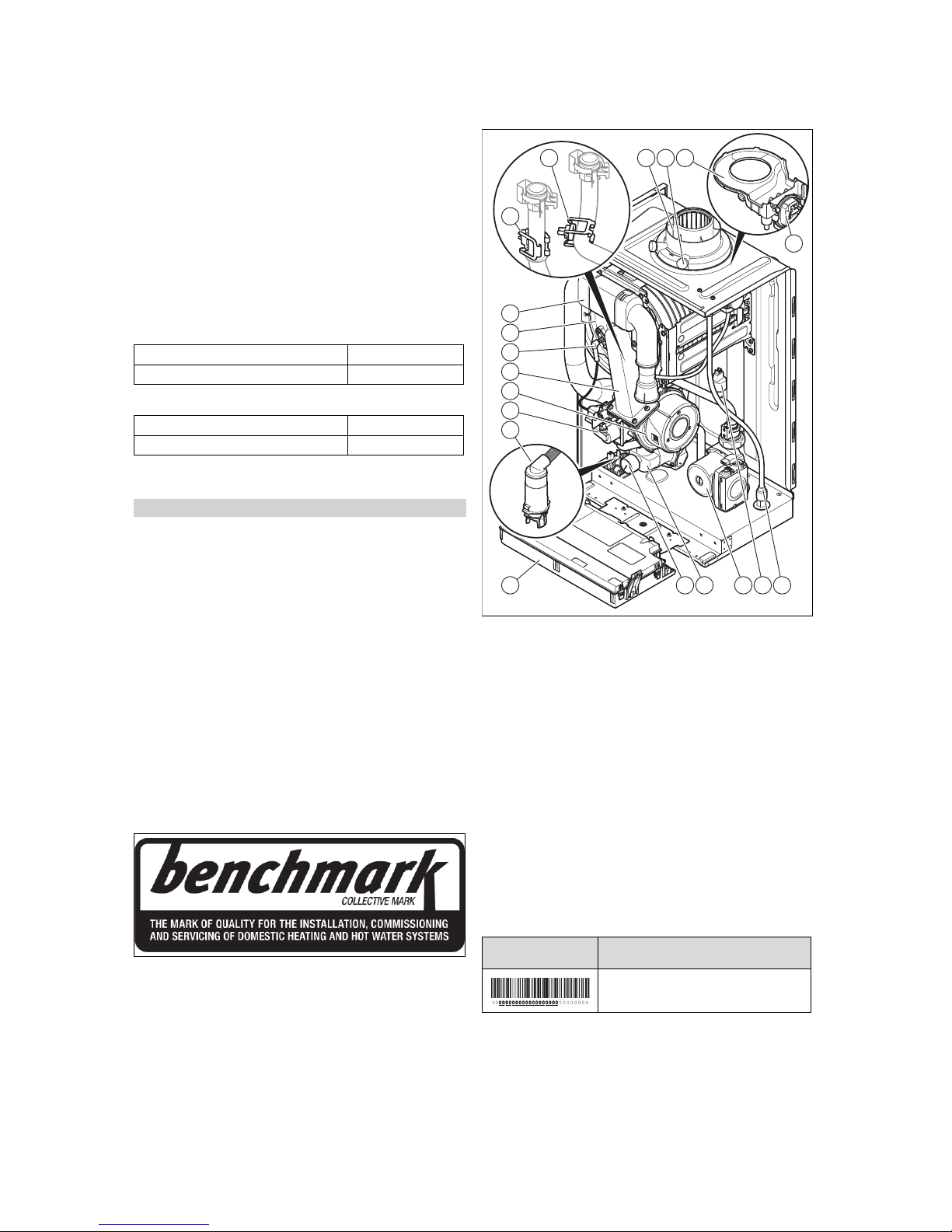
3.1 Product design
6 13 2
8
9
10
11
12
13
14
15 16 17 18
19
7
5 4
1 Rainwater drain hose
2 Hydraulic pressure
sensor
3 Heating pump
4 Dynamic air separation
system
5 Water-pressure mano-
meter
6 Electronics box
7 Condensate siphon
8 Gas valve assembly
9 Fan
10 Compact thermal
module
11 Ignition electrode
12 Integrated condensation
heat exchanger
13 Air intake pipe
14 Temperature sensor in
the heating flow
15 Temperature sensor in
the heating return
16 Connection for the
air/flue pipe
17 Flue gas measuring
stub pipe
18 Rainwater collecting
device
19 Pressure switch
3.2 Data plate
The data plate is mounted on the underside of the product in
the factory.
Information on the
data plate
Meaning
Barcode with serial number
Page 8
4 Set-up
8 Installation and maintenance instructions ecoTEC plus 0020261389_02
Information on the
data plate
Meaning
Serial number For quality control purposes; 3rd and 4th
digits = year of production
For quality control purposes; 5th and 6th
digits = week of production
For identification purposes; 7th to 16th
digits = product article number
For quality control purposes; 17th to 20th
digits = place of manufacture
... ecoTEC Plus ... Product designation
2H / 2E / 3P / 2L... Gas group and gas connection pressure
as set at the factory
II2H3P / I2E / I3P... Approved gas category
Condensing technology
Efficiency class of the boiler in accordance with EC Directive 92/42/EEC
Type: Xx3(x) Permissible flue gas connections
PMS Maximum water pressure in heating
mode
V
Hz
Electrical connection – Voltage – Frequency
Hi Lower gross calorific value
W Max. electrical power consumption
IP Protection class
Heating mode
Qn Nominal heating load range in heating
mode
Pn Nominal heat output range in heating
mode
Pnc Nominal heat output range in heating
mode (condensing technology)
Tmax Maximum flow temperature
NOx NOx class for the product
Code (DSN) Specific product code
Read the instructions.
Note
Make absolutely sure that the product is compatible with the gas group at the installation site.
3.3 Serial number
The serial number can be found on the identification plate.
3.4 SVGW (Swiss Gas and Water Industry
Association) symbol
3.5 CE marking
The CE marking shows that the products comply with the
basic requirements of the applicable directives as stated on
the data plate.
The declaration of conformity can be viewed at the manufacturer's site.
3.6 Energy Saving Trust Endorsed Products
Applicability: Great Britain
Only the most energy efficient products can carry the
‘Energy Saving Trust Endorsed Product’ brandmark making
it easy for consumers to choose products that have met strict
energy performance criteria.
Available for: Boilers, Heating controls and chemical inhibitors, the Energy Saving Trust endorsed product brandmark
gives consumers confidence that a product will cost less to
run, help lower energy bills and reduce carbon emissions.
About the Energy Saving Trust
Energy Saving Trust is an independent and impartial organisation that provides trusted energy saving advice to empower millions of people to lead affordable, low energy lifestyles. For more information visit energysavingtrust.org.uk
4 Set-up
4.1 Unpacking the product
1. Remove the product from its box.
2. Remove the wedge and protective film from all of the
product's components.
4.2 Checking the scope of delivery
Applicability: VU 446/5-5 (H-GB)
OR VU 606/5-5 (H-GB)
▶ Check that the scope of delivery is complete and intact.
Number Designation
1
Heat generator
1
Bag of set-up parts with retainer for wall-mounting, fastening accessories and condensate discharge hose
1
Cardboard box for the hydraulic connection with
expansion relief valve, drain cock, air separator
and seals
1
Cardboard box with the stopcocks for the heating
circuit
1 Cardboard box with the stopcock for the gas line
assembly
1
Documentation material including gas conversion
set
Page 9
Set-up 4
0020261389_02 ecoTEC plus Installation and maintenance instructions 9
4.3 Transporting the product
Applicability: Great Britain
OR Ireland
Important: With regard to the regulations of 1992 concerning the manual handling of loads, the product exceeds the
weight that can be lifted by a single person.
4.3.1 General
Applicability: Great Britain
OR Ireland
▶ Hold the load as close as possible to your body. Avoid
rotational movements. Instead, reposition your feet.
▶ If the product is being lifted by two persons, ensure your
movements are coordinated during lifting.
▶ Avoid bending your upper body – do not lean forwards or
to the side.
▶ Wear suitable non-slip protective gloves in order to pro-
tect your hands against sharp edges. Ensure that you are
carrying the load securely.
▶ If required, get somebody to assist you in this.
4.3.2 Unloading the cardboard box from the
delivery van
Applicability: Great Britain
OR Ireland
▶ It is recommended that two people lift the product to-
gether.
▶ Use safe lifting techniques – keep your back straight and
bend your legs at the knee.
▶ Hold the load as close as possible to your body.
▶ If the product is being lifted by two persons, ensure your
movements are coordinated during lifting.
▶ If required, get somebody to assist you in this.
4.3.3 Transporting the cardboard box from the
delivery point to the installationsite – ground
floor
Applicability: Great Britain
OR Ireland
▶ It is recommended that two people lift the product to-
gether.
▶ Use safe lifting techniques – keep your back straight and
bend your legs at the knee.
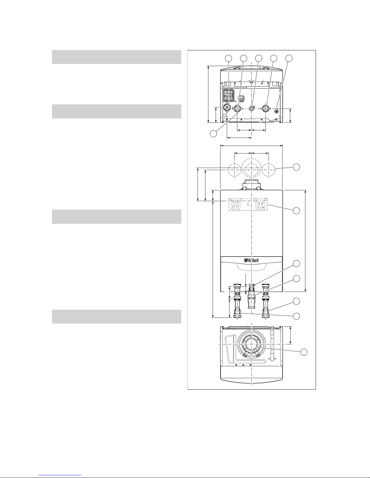
4.4 Dimensions
108
100
A
100 100
173
440
125
78
720
220
235
120120
29,5
825
6
1
2 3
12
13
4 5
7
8
9
10
11
85,5133,8
1 Condensate siphon
2 Heating flow connection
3 Gas connection
4 Heating return connec-
tion
5 Drain for the rainwater
collecting device
6 Position of the holes for
the flue system
7 Retainer for securing
the product
Page 10
4 Set-up
10 Installation and maintenance instructions ecoTEC plus 0020261389_02
8 Gas pressure connec-
tion
9 Gas stopcock
10 Stopcock in the heating
return
11 Stopcock in the heating
flow
12 Connection for the
air/flue pipe
13 Drain for the dynamic
air separation system
Dimension A
VU 446/5-5 (H-GB)
405 mm
VU 606/5-5 (H-GB)
473 mm
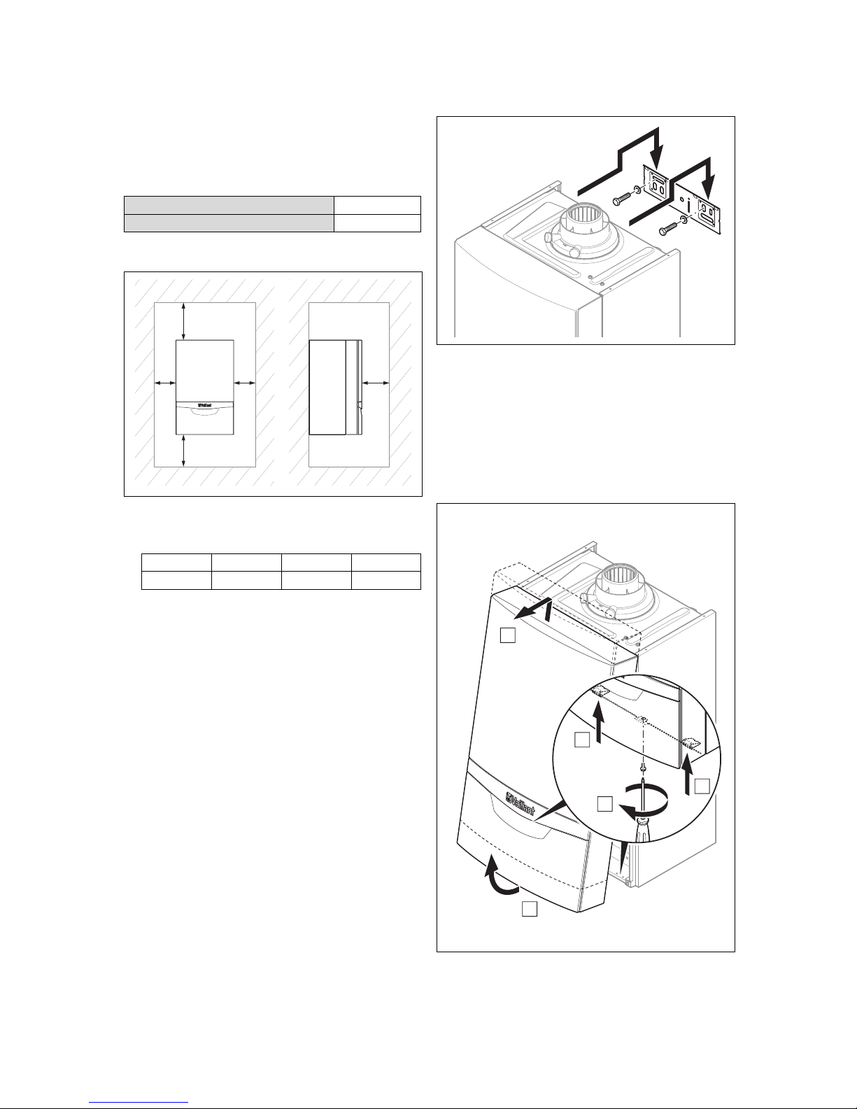
4.5 Minimum clearances
C C
AB
D
▶ When using the accessories, observe the minimum clear-
ances/installation clearances.
Minimum clearances
A B C D
≥ 275 mm ≥ 180 mm ≥ 5 mm ≥ 500 mm
– Optimum dimension (B): ≈ 250 mm
– Optimum dimension (C): ≈ 50 mm
– Dimension (D): The clearance in front of the product
to facilitate easy access for maintenance work can
be reduced to 5 mm if there is a door in front of the
product
4.6 Clearance from combustible components
It is not necessary to maintain a clearance between the
product and components made of combustible materials that
go beyond the minimum clearances.
4.7 Using the mounting template
▶ Use the mounting template to ascertain the locations at
which you need to drill holes and make breakthroughs.
4.8 Wall-mounting the product
1. Check the load-bearing capacity of the wall.
2. Note the total weight of the product.
3. Only use fixing material that is permitted for the wall.
4. If required, ensure that mounting apparatus on-site has
sufficient load-bearing capacity.
5. Wall-mount the product as described.
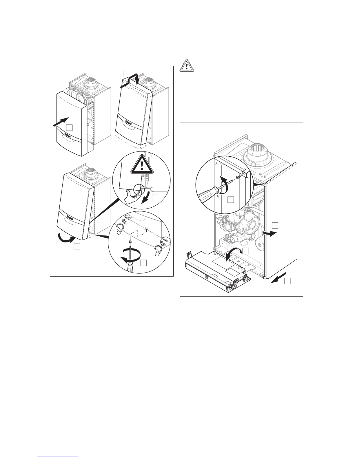
4.9 Removing/installing the front casing
4.9.1 Removing the front casing
A
B
B
C
D
1. Undo the screw (A).
2. Push in both retaining clips (B) so that the front casing
is released.
Page 11
Set-up 4
0020261389_02 ecoTEC plus Installation and maintenance instructions 11
3. Pull the front casing forwards at the bottom edge (C).
4. Lift the front casing upwards from the bracket (D).
4.9.2 Installing the front casing
C
B
A
D
E
1. Place the front casing (A) on the upper retainer (B).
2. Hinge the front casing down in the direction of the
product (C).
3. Push the front casing onto the product and, in doing so,
ensure that the insulation is not damaged (D).
4. Let the retaining clips on the front casing snap into
place.
5. Tighten the screw (E) in order to secure the front casing.
4.10 Removing/installing the side section
4.10.1 Removing the side section
Caution.
Risk of material damage caused by mech-
anical deformation.
Removing both side sections may cause
mechanical distortion in the product, which
may cause damage to the piping, for example, and potentially result in leaks.
▶ Always only remove one side section –
never both side sections at the same time.
2X
A
B
C
D
▶ Remove the side section as shown in the illustration.
4.10.2 Installing the side section
▶ Install the side section; to do so, proceed in reverse order
to how you removed it.
Page 12

5 Installation
12 Installation and maintenance instructions ecoTEC plus 0020261389_02
5 Installation
5.1 Sample system installations
▶ Use the basic installation diagrams as examples.
▶ Select the basic installation diagram based upon which
you want to configure your installation.
▶ Only install the control systems that are listed in the
tables for the basic system diagrams in order to ensure
that all of the system's functions are available.
▶ Establish the connections correctly.
▶ Observe the applicable national and international laws,
standards and directives.
▶ With older installations in particular, install a magnetic
filter at the heating circuit return in order to protect the
product against dirt from the installation.
– Ensure that there is sufficient dimensioning in order
to prevent it from blocking quickly and to prevent high
pressure losses.
▶ Observe the information on treating heating water.
(→ Page 21)
▽ If you cannot guarantee the conditions for treating
the heating water, install an external plate heat exchanger to protect the product.
▶ Install the required safety devices and system compon-
ents in the installation.
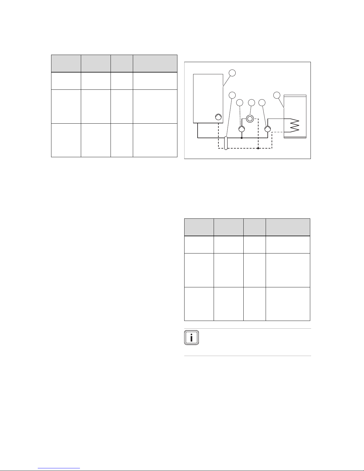
5.1.1 Basic system diagram type 1: One direct
heating circuit with one optional domestic
hot water cylinder
Note
This basic diagram type can then only be used if
the product's pump is the only pump in the system.
1
2 3 4
1 Wall-hung boiler with
internal pump
2 Prioritising diverter
valve
3 Heating circuit
4 Domestic hot water
cylinder
▶ To use this basic diagram type, ensure that the product
works within the defined operating ranges. (→ Page 30)
Number for
the basic
diagram
Control
system
Number
of circuits
Carrying out the
wiring
0020253233 Basic control 1 See appendix or
contact customer
service for special
basic diagrams.
0020253235 VRC 700
system
control
1 Contact customer
service.
0020253236 Connected
vSMART
control
1 Contact customer
service.
Note
The example of a basic installation diagram that
is shown in the appendix does not replace any
correct and expert system planning. (→ Page 52)
The settings for the internal pump are made at the factory.
▶ Ensure that there is sufficient dimensioning for the
connections and the domestic hot water cylinder.
(→ Page 15)
▶ Connect the external prioritising diverter valve to the plug
X13 on the main PCB.
▶ In order to control the cylinder's post-heating, connect
a VR 10 temperature sensor or a thermostat to the plug
that is connected to the main PCB.
Wiring diagram (→ Page 50)
To start up the prioritising diverter valve, it is not necessary
to set a diagnostics code. It is directly actuated by the product's main PCB.
5.1.2 Basic system diagram type 2: Decoupled
heating circuit plus one directly connected
domestic hot water cylinder
1
2
3 4 5
6
1 Wall-hung boiler with
internal pump
2 Prioritising diverter
valve
3 Low loss header or
plate heat exchanger
4 External pump for the
decoupled heating
circuit
5 Heating circuit
6 Domestic hot water
cylinder
▶ In order to use this basic diagram type, ensure that the
minimum flow volumes are guaranteed for the operation.
(→ Page 62)
Page 13
Installation 5
0020261389_02 ecoTEC plus Installation and maintenance instructions 13
The product can control a decoupled heating circuit and a
directly connected domestic hot water cylinder.
Number for
the basic
diagram
Control
system
Number
of circuits
Carrying out the
wiring
0020253238 VRC 700
system
control
1 Inform Customer
Service.
0020253239 VRC 700
system
control
VR 70 multifunctional
module
2 Inform Customer
Service.
0020259027 VRC 700
system
control
VR 71 multifunctional
module
>3 Inform Customer
Service.
The settings for the internal pump are made at the factory.
▶ Ensure that there is sufficient dimensioning for the
connections and the domestic hot water cylinder.
(→ Page 15)
▶ Downstream of the low loss header, select a heating
pump that is appropriate for the installation.
▶ Connect the external pump for the decoupled heating
circuit to the plug X16 for the main PCB.
▶ Connect the external prioritising diverter valve to the plug
X13 on the main PCB.
▶ Connect the temperature sensor for the low loss header
to plug X41 on the main PCB. Observe the instructions
for the low loss header.
▶ In order to control the cylinder's post-heating, connect
a VR 10 temperature sensor or a thermostat to the plug
that is connected to the main PCB.
Wiring diagram (→ Page 50)
▶ Set diagnostics code D.026 to 2.
Overview of diagnostics codes (Applicability: VU 446/55 (H-GB) OR VU 606/5-5 (H-GB)) (→ Page 42)
5.1.3 Basic system diagram type 3: Decoupled
heating circuit plus one decoupled domestic
hot water cylinder
1
2
3
4 5
6
1 Wall-hung boiler with
internal pump
2 Low loss header or
plate heat exchanger
3 External pump for the
decoupled heating
circuit
4 Heating circuit
5 External pump for the
decoupled domestic hot
water circuit
6 Domestic hot water
cylinder
The product can control a decoupled heating circuit and a
decoupled domestic hot water cylinder.
Number for
the basic
diagram
Control
system
Number
of circuits
Carrying out the
wiring
0020259029 VRC 700
system
control
1 Inform Customer
Service.
0020259030 VRC 700
system
control
VR 70 multifunctional
module
2 See appendix or
contact customer
service for special
basic diagrams.
0020259031 VRC 700
system
control
VR 71 multifunctional
module
>3 Inform Customer
Service.
Note
The example of a basic installation diagram that
is shown in the appendix does not replace any
correct and expert system planning. (→ Page 52)
The settings for the internal pump are made at the factory.
▶ Ensure that there is sufficient dimensioning for the
connections and the domestic hot water cylinder.
(→ Page 15)
▶ Downstream of the low loss header, select a heating
pump that is appropriate for the installation.
▶ Downstream of the low loss header, select a domestic
hot water pump that is suitable for the domestic hot water
cylinder.
Page 14
5 Installation
14 Installation and maintenance instructions ecoTEC plus 0020261389_02
▶ Connect the external pump for the decoupled heating
circuit to the plug X16 for the main PCB.
▶ Connect the pump for the decoupled domestic hot water
circuit to the plug X13 for the main PCB.
▶ Connect the temperature sensor for the low loss header
to plug X41 on the main PCB. Observe the instructions
for the low loss header.
▶ In order to control the cylinder's post-heating, connect
a VR 10 temperature sensor or a thermostat to the plug
that is connected to the main PCB.
Wiring diagram (→ Page 50)
▶ Set diagnostics code D.026 to 2.
Overview of diagnostics codes (Applicability: VU 446/55 (H-GB) OR VU 606/5-5 (H-GB)) (→ Page 42)
5.1.4 Basic system diagram type 4: Cascade
with two boilers plus one cylinder that is
connected to the boiler
1
3
2
6
5
4
1 Wall-hung boiler with
internal pump
2 Prioritising diverter
valve
3 Low loss header or
plate heat exchanger
4 Domestic hot water
cylinder
5 Heating circuits
6 External domestic hot
water circulation pump
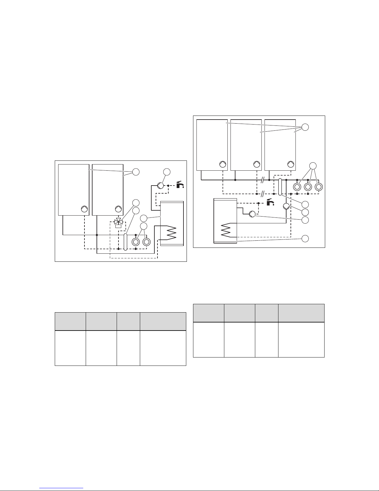
The product can control a cascade system.
Number for
the basic
diagram
Control
system
Number
of circuits
Carrying out the
wiring
0020259032 VRC 700
system
control
VR 70 multifunctional
module
2 Inform Customer
Service.
The settings for the internal pump are made at the factory.
▶ Ensure that there is sufficient dimensioning for the
connections and the domestic hot water cylinder.
(→ Page 15)
▶ Connect the domestic hot water circulation pump to the
plug X16 on the main PCB.
▶ Connect the external prioritising diverter valve to the plug
X13 on the main PCB.
▶ Connect the temperature sensor for the low loss header
to plug X41 on the main PCB. Observe the instructions
for the low loss header.
▶ In order to control the cylinder's post-heating, connect
a VR 10 temperature sensor or a thermostat to the plug
that is connected to the main PCB.
Wiring diagram (→ Page 50)
▶ Set diagnostics code D.026 to 1.
Overview of diagnostics codes (Applicability: VU 446/55 (H-GB) OR VU 606/5-5 (H-GB)) (→ Page 42)
5.1.5 Basic system diagram type 5: Cascade
with two to seven boilers + a cylinder that is
connected to the heating circuit
1
2
6
64
5
3
1 Wall-hung boiler with
internal pump
2 Heating circuits
3 Low loss header or
plate heat exchanger
4 External pump for the
decoupled domestic hot
water circuit
5 External domestic hot
water circulation pump
6 Domestic hot water
cylinder
The product can control a cascade system.
Number for
the basic
diagram
Control
system
Number
of circuits
Carrying out the
wiring
0020259033 VRC 700
system
control
VR 71 multifunctional
module
>3 Inform Customer
Service.
The settings for the internal pump are made at the factory.
▶ Ensure that there is sufficient dimensioning for the
connections and the domestic hot water cylinder.
(→ Page 15)
▶ Downstream of the low loss header, select a domestic
hot water pump that is suitable for the domestic hot water
cylinder.
▶ Connect the pump for the decoupled domestic hot water
circuit to the plug X13 for the main PCB.
▶ Connect the temperature sensor for the low loss header
to plug X41 on the main PCB. Observe the instructions
for the low loss header.
Page 15

Installation 5
0020261389_02 ecoTEC plus Installation and maintenance instructions 15
▶ In order to control the cylinder's post-heating, connect
a VR 10 temperature sensor or a thermostat to the plug
that is connected to the main PCB.
Wiring diagram (→ Page 50)
▶ Set diagnostics code D.026 to 1.
Overview of diagnostics codes (Applicability: VU 446/55 (H-GB) OR VU 606/5-5 (H-GB)) (→ Page 42)
5.2 Selecting the domestic hot water cylinder
The product can control an optional domestic hot water cylinder (recommended option for products with an output below
50 kW).
▶ Use a low loss header for products that are connected to
a domestic hot water cylinder and have a domestic hot
water output requirement of over 50 kW, . (→ Page 15)
▶ Use the following components to connect the domestic
hot water cylinder:
Domestic hot water cylinder
Cylinder Internal dia-
meter of the
connection
VU 446/5-5 (H-GB)
VIH R 300 20 mm
VU 606/5-5 (H-GB)
VIH R 500 25 mm
5.3 Selecting a low loss header
The low loss header disconnects the heat generator hydraulically from the heating system. This prevents feed head interactions between the individual circulation pumps. Furthermore, the low loss header ensures that a sufficient minimum
volume of water continuously circulates through the heat
generator.
▶ Observe the information on treating heating water.
(→ Page 21)
▽ If you cannot guarantee the conditions for treating
the heating water, install an external plate heat exchanger to protect the product.
Low loss header
Heating system spread
10 K 15 K 20 K
VU 446/5-5 (H-GB)
WH 95 WH 40-2 WH 40-2
VU 606/5-5 (H-GB)
WH 160 WH 95 WH 40-2
▶ Observe the instructions for the low loss header.
You do not require any electronic accessories when using
a low loss header. You can connect simple installations directly inside the electronics box.
▶ Observe the wiring diagram.
Wiring diagram (→ Page 50)
5.4 Requirements
▶ Make sure that the existing gas meter is capable of
passing the rate of gas supply required. (→ Page 62)
▶ If the hydraulic circuit contains a pump other than the one
for the product, only start up the product if a sufficiently
dimensioned low loss header is installed between the
heat generator circuit and the heating circuit or the cylinder charging circuit.
Low loss header (→ Page 15)
▶ If the product's pump is the only circulation pump in the
hydraulic circuit, check whether the product's feed head
is sufficient for the installation. (→ Page 30)
▽ If this is not the case, use an appropriately designed
low loss header and circulation pump.
▶ Ensure that the installation has the following compon-
ents:
– A gas stopcock for the unit
– A filling/draining device in the heating installation
▶ With older installations in particular, install a magnetic
filter at the heating circuit return in order to protect the
product against dirt from the installation.
– Ensure that there is sufficient dimensioning in order
to prevent it from blocking quickly and to prevent high
pressure losses.
5.4.1 Information on liquid gas operation
In the as-supplied condition, the product is preset for operation with the gas group indicated on the data plate.
Applicability: Except Great Britain
If you have a product that has been preset for operation with
natural gas, you must convert it to run on liquid gas. You will
need a conversion set for this. The conversion procedure
is described in the instructions supplied with the conversion
set.
5.4.2 Purging the liquid gas tank
If the liquid gas tank is not purged properly, this may result in
ignition problems.
▶ Ensure that the liquid gas tank has been purged properly
before installing the product.
▶ If required, contact the filler or the liquid gas supplier.
5.4.3 Using the correct gas type
Using the incorrect gas type may cause fault shutdowns in
the product. Ignition and combustion noise may occur in the
product.
▶ Only use the gas type listed on the data plate.
Page 16
5 Installation
16 Installation and maintenance instructions ecoTEC plus 0020261389_02
5.5 Connecting gas and water
Danger!
Risk of explosion or scalding caused by
incorrect installation.
Mechanical stresses in the connection pipes
may lead to leaks.
▶ Make sure that the connection pipes are
free from mechanical stress when they
are installed.
Caution.
Risk of material damage due to heat trans-
fer during soldering.
▶ Only solder connectors if the connectors
are not yet screwed to the service valves.
Caution.
Risk of material damage caused by
residues in the pipelines.
Welding remnants, sealing residues, dirt or
other residues in the pipelines may damage
the product.
▶ Flush the heating installation thoroughly
before installing the product.
Caution.
Risk of material damage caused by
changes to the pipes that have already
been connected.
▶ Only bend connection pipes if they have
not yet been connected to the product.
Seals made of rubber-like materials may be subject to plastic
deformation, which can lead to pressure losses.
▶ Use fibre seals.
5.5.1 Gas connection
Caution.
Risk of material damage due to the gas
leak-tightness test.
At a test pressure of >11 kPa (110 mbar), gas
leak-tightness tests may cause damage to
the gas valve assembly.
▶ If, during gas leak-tightness tests, you
also place the gas pipes and the gas valve
assembly in the product under pressure,
use a max. test pressure of 11 kPa
(110 mbar).
▶ If you cannot limit the test pressure to
11 kPa (110 mbar), close any gas stopcocks that are installed upstream from the
product before you carry out the gas leaktightness test.
▶ If, during gas leak-tightness tests, you
have closed the gas stopcock that is installed upstream of the product, relieve
the gas line pressure before you open this
gas stopcock.
▶ Do not reduce the gas pipe dimension downstream of the
gas meter.
▶ Maintain the dimension right up to the product.
▶ Select the correct gas stopcock.
▶ Remove the residues from the gas pipe by blowing
through the gas pipe beforehand.
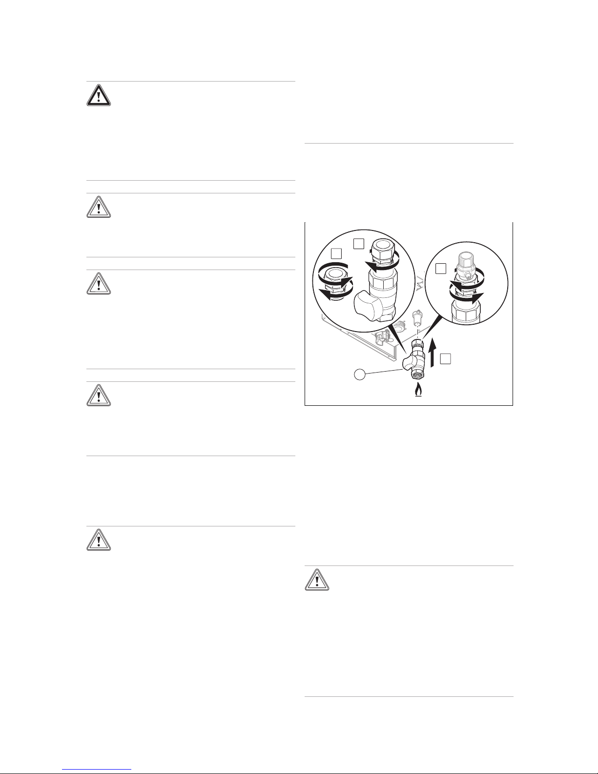
A
B
C
1
D
▶ If required, use a suitable sealant.
▶ Undo the press connection (A).
▶ Secure the gas stopcock to the compression fitting (B).
▶ Install the unit (1) on the gas pipe at the product's outlet
(C) by tightening the compression fitting (D).
▶ Install the gas pipe such that it is free from mechanical
stress in accordance with the recognised rules of technology.
▶ Purge the gas pipe before start-up.
5.5.2 Checking the gas line for leak-tightness
▶ Check the entire gas line properly for leak-tightness.
5.5.3 Hydraulic connection
Caution.
Risk of material damage caused by corro-
sion
Due to non-diffusion-tight plastic pipes in the
heating installation, air gets into the heating
water. Air in the heating water causes corrosion in the heat generator circuit and in the
product.
▶ If you use non-diffusion-tight plastic pipes
in the heating installation, ensure that no
air gets into the heat generator circuit.
Page 17
Installation 5
0020261389_02 ecoTEC plus Installation and maintenance instructions 17
Note
In order to keep heat losses to a minimum, we
recommend that you provide heat insulation for
the water pipe spigots on the product's outlet and
on the installation.
▶ If you are using plastic pipes in the heating installation,
install a safety cut-out in the heating flow.
– The safety cut-out is required to protect the heating
installation against temperature-related damage if a
fault occurs.
▶ Connect a control or a safety cut-out to the electronics.
(→ Page 20)
5.5.3.1 Connecting the heating flow and heating
return
A
B
C
D
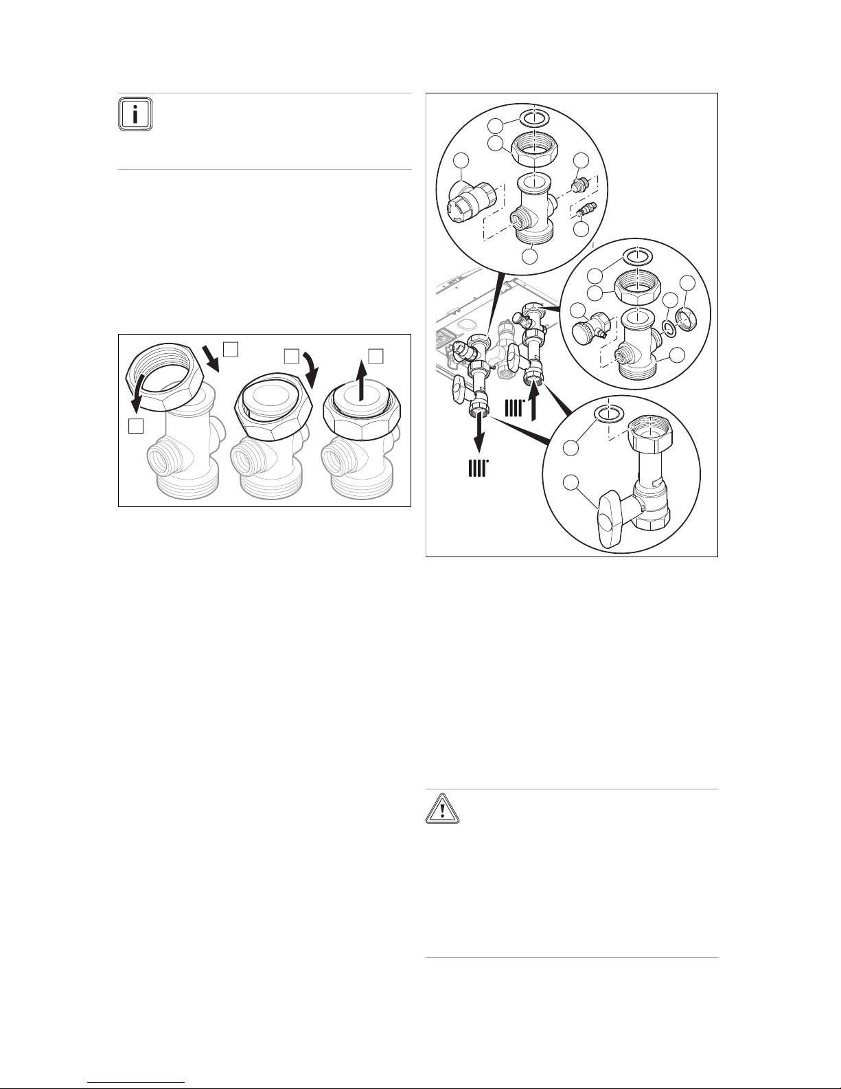
1. Attach the nut to the connection in accordance with
steps (A) to (D).
8
9
10
11
12
7
2
3
4
1
6
5
13
14
2. Assemble the heating return connection as shown by
numbers (7) to (12).
3. Assemble the heating flow connection as shown by
numbers (1) to (6).
4. Insert the seals (14).
5. Install the stopcocks (13) at the heating flow and return
connection.
6. Connect the heating circuit to the connections for the
heating flow and return.
7. Install an expansion vessel in the heating return (11), as
close to the product as possible.
– Ensure that the volumetric capacity of the expansion
vessel is sufficient for the system volume.
5.5.4 Connecting the drainage devices
Caution.
Risk of water flowing out below the
product
The water drains for the rainwater collecting
device and the dynamic air separation system are not connected to the waste-water
outflow, but water may escape.
▶ Do not place any electrical units or objects
that may be damaged by water below the
product.
Page 18
5 Installation
18 Installation and maintenance instructions ecoTEC plus 0020261389_02
5.5.4.1 Connecting the drain pipework for the
expansion relief valve
1
1. Connect the expansion relief valve (1) to a suitable
draining circuit. Make sure that the drain hose remains
open to the surrounding air.
2. Lay drain pipework for the expansion relief valve that is
as short as possible, at a downward gradient.
3. Terminate the drain pipework in such a way that escap-
ing water or steam cannot cause injury to persons or
damage to electronic components.
4. Make sure that the line end is visible.
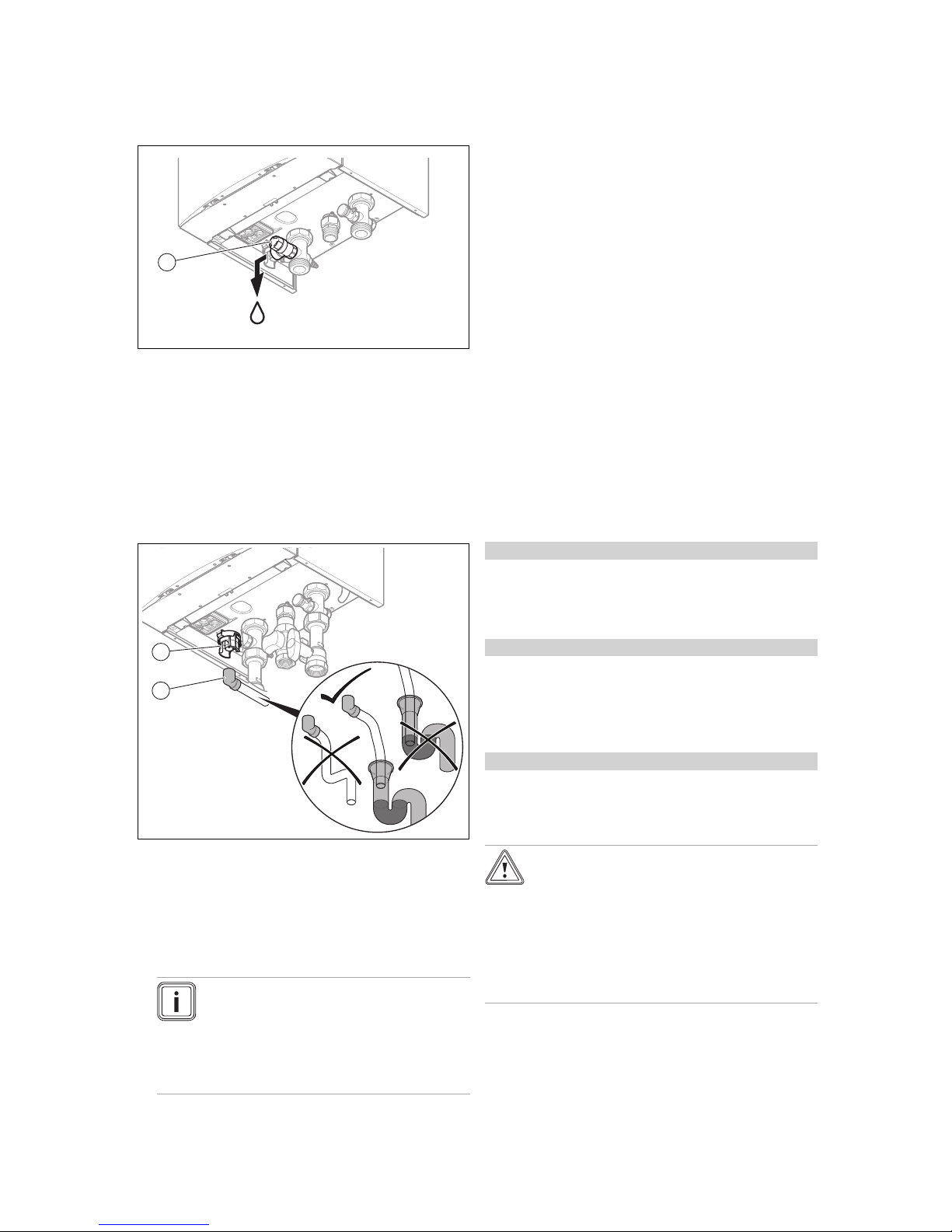
5.5.4.2 Connecting the condensate discharge pipe.
1
2
▶ Follow the instructions listed here and observe the legal
and local regulations on condensate discharge.
▶ Use PVC or any other material that is suitable for drain-
ing the non-neutralised condensate.
▶ If you cannot guarantee that the materials from which the
condensate discharge pipe is made are suitable, install a
system to neutralise the condensate.
Note
The condensate drain pipework must have a
continuous fall (45 mm per metre) and should
whenever possible terminate at a suitable
drain point within the heated envelope of the
building that will remain frost free under long
periods of low external temperatures.
▶ Ensure that the connection between the condensate dis-
charge pipe and the condensate discharge hose is not
air-tight.
▶ Connect the condensate siphon (1). Use the supplied
condensate discharge hose (2) to do this.
▶ Connect a condensate discharge pipe (21.5 mm, not in-
cluded in the scope of delivery) to the condensate discharge hose (2).
▶ During installation remove all burs from inside of cut pipe
work and avoid excessive adhesive which may trap small
pockets of water close to the pipe wall which can freeze
and build into a larger ice plug.
▶ As with other pipe work insulate the condensate dis-
charge pipe to minimise any risk of freezing and beware
when crossing cavities that the fall is maintained and the
pipe sleeved.
You can find further information in specification "BS 6798"
for installing and maintaining gas-fired boilers with a nominal
heat input below 70 kW.
5.6 Installing and connecting the air pipe and
flue pipe
5.6.1 Installing and connecting the air/flue pipe
1. You can find out which air/flue pipes may be used by
consulting the enclosed set-up instructions for the
air/flue system.
Condition: Product installed individually in living rooms
▶ Observe the information on positioning the opening for
the air/flue pipe. This information can be found in the
appendix. (→ Page 60) (Applicability: Great Britain OR
Ireland)
Condition: Product installed in cascade or in business spaces
▶ If the product is installed in cascade or in business
spaces, observe the requirements for standard
IGEM / UP / 10 for the conditions regarding aerating and
installing the attachment for the air/flue pipe.
– https://www.vaillant.co.uk
Condition: Installation in damp rooms
▶ Connect the product to a room-sealed air/flue system.
– The combustion air must not be taken from the in-
stallation site.
Caution.
Risk of poisoning due to escaping flue
gas.
Mineral-oil-based greases can damage the
seals.
▶ Instead of grease, use only water or com-
mercially available soft soap to aid installation.
2. Install the air/flue pipe using the set-up instructions.
Page 19
Installation 5
0020261389_02 ecoTEC plus Installation and maintenance instructions 19
5.6.2 B23 installation
Applicability: Except Great Britain, Except Ireland
A flue system for permitted unit type B23 (atmospheric gasfired wall-hung boilers) requires careful planning and implementation.
▶ Observe the product's technical data when planning.
▶ Use the recognised rules of technology.
5.6.3 Installation with flue non-return flap
When installing a flue non-return flap, you must set the minimum output in order to prevent ignition problems.
▶ Use diagnostics code D.085 to set the minimum output.
(→ Page 29)
Setting the minimum output of the product
D.085
(factory
setting)
Setting D.085 for
the flue non-
return flap
VU 446/5-5 (H-GB)
8 kW 13 kW
VU 606/5-5 (H-GB)
11 kW 16 kW
5.7 Electrical installation
Danger!
Risk of death from electric shock!
Power supply terminals L and N remain live
even if the on/off button is turned off:
▶
Switch off the power supply.
▶ Secure the power supply against being
switched back on again.
Only qualified electricians may carry out the electrical installation.
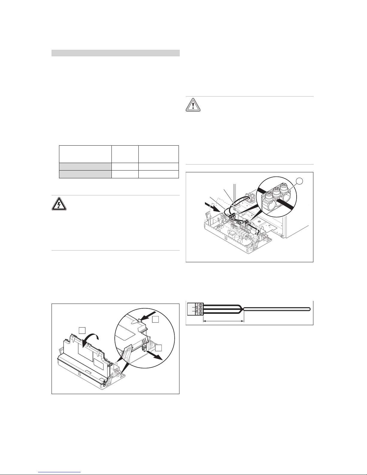
5.7.1 Opening/closing the electronics box
5.7.1.1 Opening the electronics box
1. Remove the front casing. (→ Page 10)
A
C
Bx 2
x 2
2. Tilt the electronics box forward.
3. Loosen the four clips from the retainers (A) and (B) on
the electronics box.
4. Hinge the cover (C) up.
5.7.1.2 Closing the electronics box
1. Close the cover by pushing it downwards onto the electronics box.
2. Ensure that all of the clips audibly click into the retainers.
3. Tilt the electronics box upwards.
5.7.2 Carrying out the wiring
Caution.
Risk of material damage caused by incor-
rect installation.
Mains voltage at incorrect terminals and plug
terminals may destroy the electronics.
▶ Do not connect the eBUS terminals (+/‑)
to the mains voltage.
▶ Only connect the power supply cable to
the terminals marked for the purpose.
230V
24V / eBus
1
1. Route the connection cables for the components to
be connected in the cable trunking on the left of the
underside of the product.
2. Use the strain reliefs (1).
3. Shorten the connection cables as necessary.
30 mm max.
4. Only strip the outer sheathing of flexible lines to a maximum of 30 mm to prevent short circuits if a strand accidentally comes loose.
5. Ensure the inner conductor insulation is not damaged
when stripping the outer sheathing.
6. Only strip inner conductors just enough to establish
good, sound connections.
7. To avoid short circuits resulting from loose individual
wires, fit conductor end sleeves on the stripped ends of
the conductors.
8. Screw the plug to the connection cable.
9. Check whether all conductors are properly fastened
to the connection terminals of the plug. Remedy this if
necessary.
10. Plug the plug into the slot provided on the PCB in ac-
cordance with the wiring diagram in the appendix.
Page 20
5 Installation
20 Installation and maintenance instructions ecoTEC plus 0020261389_02
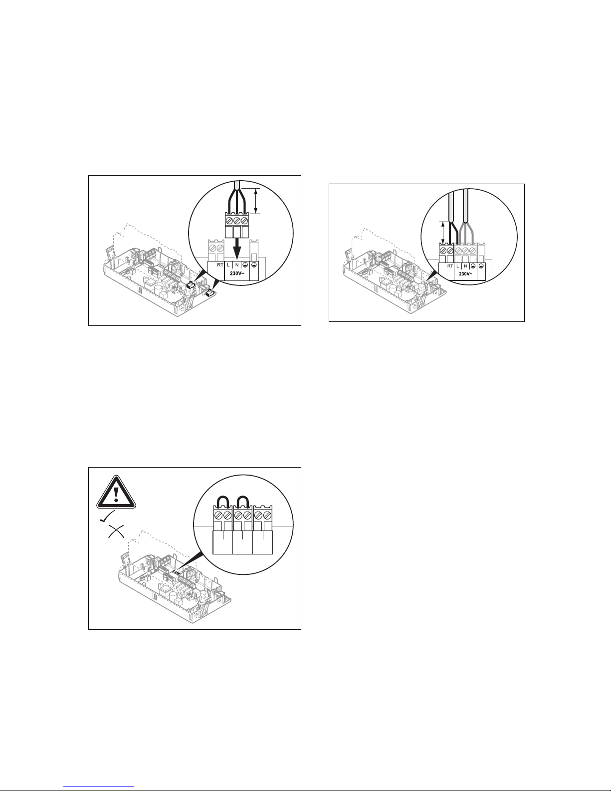
5.7.3 Establishing the power supply
1. Provide one common power supply for the boiler and
for the corresponding control:
– Power supply: Single-phase, 230 V, 50 Hz
– Fuse protection: ≤ 3 A
2. Observe all valid regulations.
– The applicable regulations state that the connection
must be made via an electrical partition with a contact gap of at least 3 mm at each pole.
≤ 30
mm
3. Use a flexible line for the power supply cable, which is
routed through the grommet into the product.
4. Carry out the wiring. (→ Page 19)
5. Screw the supplied plug to a three-core power supply
cable that complies with the relevant standards.
6. Plug the plug for the connection cable into the slot 230V
on the main PCB.
7. Close the electronics box. (→ Page 19)
8. Make sure that access to the power supply is always
available and is not covered or blocked.
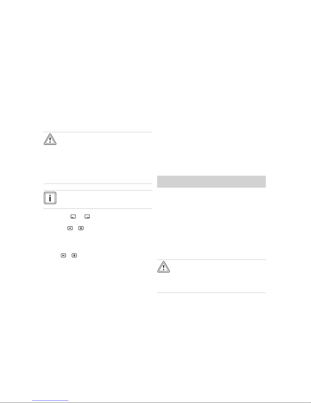
5.7.4 Connecting controls to the electronics
24V=
230V~
–
+
24V=
RT
BUS
Burner
off
1. Open the electronics box. (→ Page 19)
2. Carry out the wiring. (→ Page 19)
3. Alternatives 1 ‒ Connecting the weather-com-
pensated eBUS control or eBUS room temperature control:
▶ Connect the control to the BUS plug.
▶ Bridge the 24V=RT plug if it is not already bridged.
3.
Alternatives 2 ‒ Connecting a 24 V extra low
voltage room temperature control:
▶ Instead of the bridge, connect the control to the 24 V
plug.
3.
Alternatives 3 ‒ Connecting limit thermostats
for the underfloor heating:
▶ Connect the limit thermostat to the Burner off plug
instead of the bridge.
3.
Alternatives 4 ‒ Connecting the 230 V low
voltage room temperature control:
≤ 30
mm
▶ Connect the control to the L main plug and to the RT
plug.
▶
Remove the bridge from the 24V=RT plug.
4. Close the electronics box.
5. To trigger the Comfort pump operating mode (pump
runs permanently) using a multi-circuit control, change
the diagnostics code D.018 pump operating mode from
Eco (pump runs intermittently) to Comfort. (→ Page 30)
5.7.5 Connecting the hydraulic accessory
▶ Connect the hydraulic accessory in accordance with the
selected basic system diagram. (→ Page 12)
5.7.6 Connecting additional components
You can use the integrated additional relay to actuate an
additional component.
You can use the optional multi-functional module to actuate
two further additional components.
5.7.6.1 Using the additional relay
1. Connect an additional component directly to the integrated additional relay using the grey plug on the PCB.
2. Carry out the wiring. (→ Page 19)
3. Select D.026 to actuate the connected component.
(→ Page 29)
Page 21
Operation 6
0020261389_02 ecoTEC plus Installation and maintenance instructions 21
5.7.6.2 Using the VR 40 (2 in 7 multi-functional
module)
1. Install the components in accordance with the respect-
ive instructions.
2. Select D.027 to actuate relay 1 on the multi-functional
module. (→ Page 29)
3. Select D.028 to actuate relay 2 on the multi-functional
module. (→ Page 29)
6 Operation
6.1 Operating concept
The operating concept and the display and setting options of
the end user level are described in the operating instructions.
6.2 Calling up the installer level
Caution.
Risk of material damage caused by incor-
rect handling.
Incorrect settings at installer level may cause
damage and operating faults to the heating
installation.
▶ You must only access the installer level if
you are an approved competent person.
Note
The installer level is protected against unauthorised access using an access code.
1. Press the and ("i") buttons at the same time.
◁ The following menu appears in the display.
2. Use the or button to scroll until the Installer
level menu item appears.
3. Confirm by pressing (OK).
◁ The text Enter code and the value 00 appear in the
display.
4. Use or to set the value 17 (access code).
5. Confirm by pressing (OK).
◁ The installer level appears with a selection of menu
items.
6.3 Live Monitor (status codes)
Menu → Live monitor
Status codes in the display provide information on the product's current operating mode.
Status codes – Overview (→ Page 45)
6.4 Calling up appliance config. and diagnostics
menu
To recheck and reset the most important system parameters,
call up the Appliance config. menu item.
Menu → Installer level → Appliance config.
The setting options for more complex installations can be
found in the Diagnostics menu.
Menu → Installer level → Diagnostics menu
Overview of diagnostics codes (Applicability: VU 446/5-5
(H-GB) OR VU 606/5-5 (H-GB)) (→ Page 42)
6.5 Using test programmes
As well as the installation assistants, you can also call up the
test programmes for start-up, service and troubleshooting.
Menu → Installer level → Test programs
In addition to the Function menu, the product comprises
an Electronics self-test but also Check programs
(→ Page 25).
7 Start-up
7.1 Carrying out the initial start-up
Applicability: Great Britain
OR Ireland
Initial start-up must be carried out by a customer service
technician or an authorised competent person using the
commissioning checklist. The commissioning checklist in the
appendix (→ Page 56) (Applicability: Great Britain) of the
installation instructions must be filled in and stored carefully
along with the unit's documentation.
▶ Carry out the start-up procedure using the commissioning
checklist in the appendix.
▶ Fill in and sign the commissioning checklist.
7.2 Checking and treating the heating
water/filling and supplementary water
Caution.
Risk of material damage due to poor-qual-
ity heating water
▶ Ensure that the heating water is of suffi-
cient quality.
▶ Before filling or topping up the installation, check the
quality of the heating water.
Checking the quality of the heating water
▶ Remove a little water from the heating circuit.
▶ Check the appearance of the heating water.
▶ If you ascertain that it contains sedimentary materials,
you must desludge the installation.
▶ Use a magnetic rod to check whether it contains mag-
netite (iron oxide).
▶ If you ascertain that it contains magnetite, clean the in-
stallation and apply suitable corrosion-protection measures, or fit a magnetic filter.
Page 22

7 Start-up
22 Installation and maintenance instructions ecoTEC plus 0020261389_02
▶ Check the pH value of the removed water at 25 °C.
▶ If the value is below 8.2 or above 10.0, clean the installa-
tion and treat the heating water.
▶ Ensure that oxygen cannot get into the heating water.
Checking the filling and supplementary water
▶ Before filling the installation, measure the hardness of the
filling and supplementary water.
Treating the filling and supplementary water
▶ Observe all applicable national regulations and technical
standards when treating the filling and supplementary
water.
Provided the national regulations and technical standards
do not stipulate more stringent requirements, the following
applies:
You must treat the heating water in the following cases:
– If the entire filling and supplementary water quantity dur-
ing the operating life of the system exceeds three times
the nominal volume of the heating installation, or
– If the guideline values listed in the following table are not
met, or
–
If the pH value of the heating water is less than 8.2 or
more than 10.0.
Applicability: New Zealand
Total
heating
output
Water hardness at specific system volume
1)
≤ 20 l/kW
> 20 l/kW
≤ 50 l/kW
> 50 l/kW
kW °dH mol/m³ °dH mol/m³ °dH mol/m³
< 50
< 16.8
< 3 11.2 2 0.11 0.02
> 50
to ≤ 200
11.2 2 8.4 1.5 0.11 0.02
> 200
to ≤ 600
8.4 1.5 0.11 0.02 0.11 0.02
> 600 0.11 0.02 0.11 0.02 0.11 0.02
1) Nominal capacity in litres/heating output; in the case of multiboiler systems, the smallest single heating output is to be used.
Applicability: Great Britain
OR Ireland
Total
heating
output
Water hardness at specific system volume
1)
≤ 20 l/kW
> 20 l/kW
≤ 50 l/kW
> 50 l/kW
kW
ppm
CaCO₃
mol/m³ppm
CaCO₃
mol/m³ppm
CaCO₃
mol/
m³
< 50 < 300 < 3 200 2 2 0.02
> 50
to ≤ 200
200 2 150 1.5 2 0.02
> 200
to ≤ 600
150 1.5 2 0.02 2 0.02
> 600 2 0.02 2 0.02 2 0.02
1) Nominal capacity in litres/heating output; in the case of multiboiler systems, the smallest single heating output is to be used.
Applicability: Great Britain
OR Ireland
OR New Zealand
Caution.
Risk of material damage if the heating
water is treated with unsuitable additives.
Unsuitable additives may cause changes in
the components, noises in heating mode and
possibly subsequent damage.
▶ Do not use any unsuitable antifreeze and
corrosion inhibitors, biocides or sealants.
No incompatibility with our products has been detected to
date with proper use of the following additives.
▶ When using additives, follow the manufacturer's instruc-
tions without exception.
We accept no liability for the compatibility of any additive or
its effectiveness in the rest of the heating system.
Additives for cleaning measures (subsequent
flushing required)
– Adey MC3+
– Adey MC5
– Fernox F3
– Sentinel X 300
– Sentinel X 400
Additives intended to remain permanently in the
installation
– Adey MC1+
– Fernox F1
– Fernox F2
– Sentinel X 100
– Sentinel X 200
Additives for frost protection intended to remain
permanently in the installation
– Adey MC ZERO
– Fernox Antifreeze Alphi 11
– Sentinel X 500
▶ If you have used the above-mentioned additives, inform
the end user about the measures that are required.
▶ Inform the end user about the measures required for frost
protection.
Page 23

Start-up 7
0020261389_02 ecoTEC plus Installation and maintenance instructions 23
7.3 Filling the condensate siphon
1
2
3
C
B
A
1. Unclip the lower section of the siphon (1) from the upper section of the siphon (2) without removing the product's front casing.
2. Remove the float (3).
3. Fill the lower section of the siphon with water up to 10
mm below the upper edge of the condensate discharge
pipe.
4. Re-insert the float (3).
Note
Check whether the float is present in the
condensate siphon.
5. Clip the lower section of the siphon
(1) into the upper
section of the siphon (2).
7.4 Filling the heating installation
1. Flush the heating installation thoroughly before filling it.
2. Observe the information on treating heating water.
(→ Page 21)
▽ If you cannot guarantee the conditions for treating
the heating water, install an external plate heat exchanger to protect the product.
4
3
2
1
3. Open the plugs (2) and then connect the filling/draining
cock connection to a heating water supply in accordance with the relevant standards.
4. Open the heating water supply.
5. Open all thermostatic radiator valves.
6. If necessary, check that both service valves on the
product are open.
7. Slowly open the filling/draining cock (1) so that the water flows into the heating installation.
8. Open the air separator (3) and wait until the water flows
out of the air separator without bubbles.
9. Purge all of the radiators until the entire heating installation is filled with water.
10. Close all purging valves.
11. Use the manometer (4) to monitor the rising filling pres-
sure in the heating installation.
– To optimise the purging, the pressure should be lim-
ited in such a way that it lies in the first third of the
grey display field on the manometer. Once the purging procedure is complete, the digital manometer
can be used to set the hydraulic pressure depending on the distribution network (required feed head,
multilevel installation, etc.).
12. Fill it with water until the required filling pressure is
reached.
Filling pressure
Recommended
filling pressure
Maximum filling
pressure
VU 446/5-5
(H-GB)
0.15 … 0.25 MPa
(1.50 … 2.50 bar)
< 0.40 MPa
(< 4.00 bar)
VU 606/5-5
(H-GB)
0.15 … 0.25 MPa
(1.50 … 2.50 bar)
< 0.40 MPa
(< 4.00 bar)
13. Close the filling/draining cock and the heating water
supply.
14. Check all of the connections and the entire circuit for
leaks.
Page 24

7 Start-up
24 Installation and maintenance instructions ecoTEC plus 0020261389_02
7.5 Starting up the product
▶ Press the product's on/off button.
◁ The basic display appears on the display.
7.6 Running the installation assistants
The installation assistant is displayed whenever the product
is switched on until it has been successfully completed.
It provides direct access to the most important check
programmes and configuration settings for starting up the
product.
▶ Confirm the launch of the installation assistant.
◁ All heating demands are blocked whilst the installa-
tion assistant is active.
▶ To access the next item, confirm by pressing Next in
each case.
▽ If you do not confirm the launch of the installation
assistant, it is closed 10 seconds after you switch on
the unit and the basic display then appears.
7.6.1 Language
▶ Set the required language.
▶ Press OK twice to confirm the set language and to avoid
unintentionally changing it.
If you have unintentionally set a language that you do not
understand, proceed as follows to change it:
▶ Press and hold the and buttons at the same time.
▶ Also press the reset button for a short time.
▶ Press and hold and until the display shows the
language setting option.
▶ Select the required language.
▶ Press OK twice to confirm this change.
7.6.2 Filling the heating circuit
This function is displayed but it is not yet active for this
product type.
7.6.3 Purging the heating installation
Purging (corresponds to check programme P.00) is activated
automatically by the installation assistant and remains in
the display for as long as the purging is active. Without the
installation assistant, purging also occurs automatically.
The programme must be carried out once or else the product
will not start.
▶ If the radiators in the house are equipped with thermo-
static valves, ensure that all thermostatic valves are open
so that the circuit can be purged effectively.
▶ To ensure that the purging takes place correctly, the
filling pressure of the heating installation must not fall below the minimum filling pressure.
– Minimum heating installation filling pressure:
0.08 MPa (0.80 bar)
Note
Check programme P.00 runs for approx.
6.5 minutes for each circuit.
At the end of the filling procedure, the filling
pressure of the heating installation must be at
least 0.02 MPa (0.2 bar) above the counterpressure of the expansion vessel ("Exp")
(P
Installation
≥ P
Exp
+ 0.02 MPa (0.2 bar)).
If, at the end of the purge programme, the flow rate that is
achieved is insufficient, fault code F75 appears in conjunction with diagnostics code D.149 = 8. The purge programme
is considered to have failed and is repeated.
▶ Ensure that all of the stopcocks in the hydraulic installa-
tion are open.
▶ Ensure that the thermostatic valves on the radiators are
open.
▶ Press the product's reset button to restart an automatic
purge programme.
▶ Check all connections for tightness.
7.6.4 Setting the target heating temperature
You can use this setting to adjust the required target heating
temperature.
7.6.5 Setting the target hot water temperature
This setting is only possible if a domestic hot water cylinder (optional) is installed in the system. This means that the
required target hot water temperature can be adjusted (by
post-heating the cylinder).
7.6.6 Setting the maximum heating output
The product's maximum heating output can be adjusted to
the installation's heat demand. Use diagnostics code D.000
to set a value that corresponds to the unit output in kW.
7.6.7 Additional relay and multi-functional module
Additional components that are connected to the installation can be adjusted in these menu items. You can use diagnostics codes D.026, D.027 and D.028 to change the setting.
7.6.8 Telephone: Competent person
You can store your telephone number in the product menu.
The end user can view the telephone number. The telephone
number can be up to 16 digits long and must not contain any
spaces.
7.6.9 Ending the installation assistant
Once the installation assistant has been completed and confirmed, it will not start up automatically next time the unit is
switched on.
7.6.10 Restarting the installation assistants
You can restart the installation assistant at any time by calling it up in the menu.
Menu → Installer level → Start inst. assistant
Page 25

Start-up 7
0020261389_02 ecoTEC plus Installation and maintenance instructions 25
7.7 Preventing low water pressure
To prevent damage to the heating installation that is caused
by low filling pressure, the product is fitted with a water
pressure sensor. If the filling pressure falls below 0.1 MPa
(1.0 bar), the product indicates low pressure by displaying a
flashing pressure value. If the filling pressure falls below 0.05
MPa (0.5 bar), the product switches off. The display shows
F.22.
▶ Top up the heating water to start the product up again.
The pressure value flashes on the display until a pressure of
0.11 MPa (1.1 bar) or higher has been reached.
▶ If you notice frequent drops in pressure, determine and
eliminate the cause.
The purging function is automatically active after a filling
procedure.
7.8 Flushing the heating installation for the first
time ("cold")
Applicability: Great Britain
OR Ireland
Note
The complete heating system must be flushed
at least twice: Once with cold water and once
with hot water in accordance with the following
instructions.
1. Check whether all thermostatic radiator valves and both
service valves on the product are open.
2. Connect a hose to the drain valve that is located at the
lowest position in the heating system.
3. Open the radiator valves and the drain valves so that
the water can drain quickly. Start at the next point in the
installation and open the purging valves on the radiators
so that the contaminated water can completely drain.
4. Close the drain cocks.
5. Refill the heating system with water.
6. Check that the expansion relief valve of the heating
system is functioning correctly by turning the handle
on the valve.
7. Check the pressure in the heating system and top up
with water if necessary.
8. Close the filling valve and the cold water tap.
7.9 Using check programmes
Menu → Installer level → Test programs → Check programs
You can activate various special functions in the product by
using various check programmes.
Display Meaning
P.00 Purging check programme:
The internal pump is cyclically actuated.
The heating circuit and the domestic hot water circuit
are purged via the air separation system.
1 x : Start the heating circuit purging
2 x ( → ): Start the domestic hot water circuit
purging
3 x ( → ): Restart the heating circuit purging
1 x (Cancel): End the purge programme
Note
The purging programme runs for 6.5 minutes per
circuit and then terminates.
P.01 Maximum load check programme:
After successful ignition, the product is operated at
maximum heat input if the flow rate in the heating
circuit permits this. Otherwise, the power is reduced
in order to adapt to the flow rate.
P.02 Minimum load check programme:
After successful ignition, the product is operated at
minimum heat input if the flow rate in the heating
circuit permits this. Otherwise, the product does not
ignite and it remains in waiting mode (status code
S.85).
Note
If the product is in error condition, you cannot start
any check programmes. You can detect an error
condition by the fault symbol shown in the left
bottom corner of the display. You must first reset.
To terminate the check programmes, you can select (Can-
cel) at any time; this does not apply for initial start-up, however. The purging cycle must be completely carried out once
so that the burner can ignite.
7.10 Check and gas setting
7.10.1 Checking the factory setting
Caution.
An incorrect gas type setting may cause
malfunctions or a reduction in the service
life of the product.
If the product design does not match the local
gas type, this may lead to malfunctions or to
some components wearing prematurely.
▶ Before you start up the product, compare
the gas type information on the data plate
with the gas type group available at the
installation site.
The product's combustion has been factory tested and is
preset for operation with the gas type indicated on the data
plate. In some supply areas, these settings may need to be
adjusted at the installation site.
Page 26

7 Start-up
26 Installation and maintenance instructions ecoTEC plus 0020261389_02
Condition: The product design is not compatible with the local gas type
▶ Do not start up the product.
▶ Carry out a gas conversion in accordance with your in-
stallation.
Condition: The product design is compatible with the local gas type
▶
Proceed as described below.
7.10.2 Checking the leak-tightness of the flue gas
installation and flue gas recirculation
Applicability: Great Britain
OR Ireland
1. Check the flue gas installation is intact in accordance
with the latest gas safe technical bulletin and information supplied in the installation instructions.
2. For extended flue gas installations check for flue gas
recirculation using the air analysis point.
3. Use a flue gas analyser.
4. If you discover CO or CO2in the supply air, search for
the leak in the flue gas installation or for signs of flue
gas recirculation.
5. Eliminate the damage properly.
6. Check again whether the supply air contains any CO or
CO2.
7. If you cannot eliminate the damage, do not start up the
product.
7.10.3 Checking the gas flow rate
Applicability: Great Britain
OR Ireland
The boiler is fitted with a multifunctional automatic gas valve
which ensures that the precise air/gas ratio is provided under all operating conditions. The gas flow rate has been set
during production and does not require adjustment. With the
front casing fitted check the gas flow rate of the boiler as follows:
▶ Start up the product with the check programme P.01.
▶ In addition, ensure that maximum heat can be dissipated
into the heating system by turning up the room thermostat.
▶ Wait at least 5 minutes until the boiler has reached its
operating temperature.
▶ Ensure that all other gas appliances in the property are
turned off.
▶ Measure the gas flow rate at the gas meter.
▶ Compare the measured values with the corresponding
values in the table.
Applicability: VU 446/5-5 (H-GB)
Qnw from
the data
plate
H gas in m³/h P gas in m³/h
Nom.
+5% −10%
Nom.
+5% −10%
8.1 0.86 0.90 0.77 − − −
9.5 − − − 0.39 0.41 0.35
26.7 2.82 2.96 2.54 − − −
27.4 − − − 1.19 1.25 1.07
45.2 4.78 5.02 4.30 1.85 1.94 1.67
Applicability: VU 606/5-5 (H-GB)
Qnw from
the data
plate
H gas in m³/h P gas in m³/h
Nom.
+5% −10%
Nom.
+5% −10%
11.3 1.19 1.25 1.08 0.46 0.49 0.42
35.7 3.77 3.96 3.39 1.46 1.53 1.31
60.0 6.34 6.66 5.71 2.45 2.58 2.21
Condition: Gas flow rate not in the permissible range
▶ Check all of the piping and ensure that the gas flow rates
are correct.
▶ Only put the product into operation once the gas flow
rates have been corrected.
Condition: Gas flow rate in the permissible range
▶ End check programme P.01.
▶ Allow the boiler to cool down by allowing pump overrun to
operate for a minimum of two minutes.
▶ Record the boiler maximum gas flow rate onto the
Benchmark gas boiler commissioning checklist.
7.10.4 Checking the gas flow pressure
A
B
D
C
1. Ensure that the gas inlet working pressure can be
obtained with all other gas appliances in the property
working.
2. Close the gas stopcock.
3. Alternatives 1 ‒ Measuring the gas pressure at
the gas valve assembly::
▶ Undo the test nipple screw (A) on the gas valve
assembly.
Page 27

Start-up 7
0020261389_02 ecoTEC plus Installation and maintenance instructions 27
▶ Connect a digital manometer or U-tube manometer
(B).
3.
Alternatives 2 ‒ Measuring the gas pressure at
the gas connection::
▶ Undo the test nipple screw (C) at the gas connec-
tion.
▶ Connect a digital manometer or U-tube manometer
(D).
4. Open the gas stopcock.
5. Open the hydraulic circuit's valves.
6. Start up the product with the check programme P.01.
7. In addition, ensure that maximum heat can be dissipated into the heating system by turning up the room
thermostat.
8. With the boiler operating at full load check that the gas
inlet working pressure at the reference test point (1)
complies with the requirements.
Gas connection pressure/gas flow pressure
difference for G20
Permitted gas flow
pressure that is
measured at point
(D)
Permitted gas flow
pressure that is
measured at point
(B)
VU 446/5-5
(H-GB)
1.70 … 2.50 kPa
(17.00
… 25.00 mbar)
1.60 … 2.40 kPa
(16.00
… 24.00 mbar)
VU 606/5-5
(H-GB)
1.70 … 2.50 kPa
(17.00
… 25.00 mbar)
1.55 … 2.35 kPa
(15.50
… 23.50 mbar)
Gas connection pressure/gas flow pressure
difference for G31
Permitted gas flow
pressure that is
measured at point
(D)
Permitted gas flow
pressure that is
measured at point
(B)
VU 446/5-5
(H-GB)
2.50 … 4.50 kPa
(25.00
… 45.00 mbar)
2.45 … 4.45 kPa
(24.50
… 44.50 mbar)
VU 606/5-5
(H-GB)
2.50 … 4.50 kPa
(25.00
… 45.00 mbar)
2.35 … 4.35 kPa
(23.50
… 43.50 mbar)
9. Should the pressure recorded at the reference test point
in the boiler be lower than indicated check if there is
any blockage in the pipework or if the pipework is undersized.
Condition: Gas flow pressure not in the permissible range
Caution.
Risk of material damage and operating
faults caused by incorrect gas flow pressure.
If the gas flow pressure lies outside the permissible range, this can cause operating
faults in and damage to the product.
▶ Do not make any adjustments to the
product.
▶ Check the gas installation.
▶ Do not start up the product.
▶ If you cannot correct the failure, notify the gas supply
company and proceed as follows:
▶ End check programme P.01.
▶ Allow the boiler to cool down by allowing pump overrun
to operate for a minimum of two minutes.
▶ Close the gas stopcock.
▶ Remove the pressure gauge and retighten the sealing
screw (A) or (C) for the measuring nipple.
▶ Open the gas stopcock.
▶ Check the test nipple for gas tightness.
▶ Close the gas stopcock.
▶ Install the front casing. (→ Page 11)
▶ Disconnect the product from the power grid.
▶ You must not start up the boiler.
Condition: Gas flow pressure in the permissible range
▶ End check programme P.01.
▶ Allow the boiler to cool down allowing pump overrun to
operate for a minimum of two minutes.
▶ Close the gas stopcock.
▶ Remove the pressure gauge and retighten the sealing
screw (A) or (C) for the measuring nipple.
▶ Open the gas stopcock.
▶ Check the test nipple for gas tightness.
▶ Install the front casing. (→ Page 11)
▶ Reset boiler controls for normal operation.
Applicability: Great Britain
OR Ireland
▶ Record the appliance gas inlet working pressure (kPa
resp. mbar) in the Benchmark gas boiler commissioning checklist.
7.10.5 Checking the CO₂ content and, if necessary,
adjusting it (air ratio setting)
1. Ensure that the heating circuit valves are open.
2. Start up the product with the check programme P.01.
3. Wait at least five minutes until the product reaches its
operating temperature.
1
4. Use a combustion analyser to measure the CO₂ content
at the flue gas analysis point (1).
5. Compare the measured value with the corresponding
value in the table.
Page 28

7 Start-up
28 Installation and maintenance instructions ecoTEC plus 0020261389_02
Set values, G20 natural gas (→ Page 61)
Set values, G31 liquefied petroleum gas (→ Page 62)
6. Remove the front casing. (→ Page 10)
Applicability: VU 446/5-5 (H-GB)
Condition: The CO₂ content must be adjusted
1
▶ Set the CO₂ content (value with front casing removed)
by turning the screw (1).
▶ Only carry out the adjustment in increments of 1/8
turn and wait approximately 1 minute after each adjustment until the value stabilises.
Note
Turn anti-clockwise: Lower CO₂ content
Turn to clockwise: Higher CO₂ content
Applicability: VU 606/5-5 (H-GB)
Condition: The CO₂ content must be adjusted
1
▶ Set the CO₂ content (value with front casing removed)
by turning the screw (1).
▶ Only carry out the adjustment in increments of 1/8
turn and wait approximately 1 minute after each adjustment until the value stabilises.
Note
Turn to the left: Higher CO₂ content
Turn to the right: Lower CO₂ content
7. Once the setting is finished, lock the check programme.
8. If an adjustment is not possible in the specified adjustment range, do not start up the product.
– Inform Customer Service.
9. Install the front casing. (→ Page 11)
7.10.6 Gas conversion procedure
Note
The conversion procedure is described in the instructions that are included with the conversion
set that is supplied with the product.
▶ Follow the instructions in the manual for the conversion
set to carry out the gas conversion on the product.
7.11 Checking leak-tightness
▶ Check the gas pipe, the heating circuit and the hot water
circuit for leak-tightness.
▶ Check that the air/flue pipe has been installed correctly.
Condition: Room-sealed operation
▶ Check whether the vacuum chamber has been closed
tightly.
7.11.1 Checking the heating mode
1. Ensure that there is a heating demand at the product.
2. Call up Live monitor.
Status codes – Overview (→ Page 45)
◁ If the product is working correctly, the display shows
S.04.
7.11.2 Checking the hot water generation
Condition: Cylinder connected
Danger!
Risk of death from legionella.
Legionella multiply at temperatures below
60 °C.
▶ Ensure that the end user is familiar with
all of the Anti-legionella measures in order to comply with the applicable regulations regarding legionella prevention.
▶ Make sure that the cylinder thermostat is requesting
heat.
1. Call up Live monitor.
Status codes – Overview (→ Page 45)
◁ If the cylinder charging is carried out correctly, S.24
appears in the display.
2. If you have connected a control to the installation and
you can set the domestic hot water temperature on this
control, set the domestic hot water temperature on the
boiler to the maximum possible temperature.
3. Adjust the target temperature for the connected domestic hot water cylinder to the control.
◁
The boiler adopts the set target temperature which
is set on the control.
Page 29

Adapting the unit to the heating installation 8
0020261389_02 ecoTEC plus Installation and maintenance instructions 29
7.12 Thoroughly flushing the heating installation
("hot")
Applicability: Great Britain
OR Ireland
1. Operate the appliance until the boiler and the heating
system are up to temperature.
2. Check the heating system for leaks.
3. Connect a hose to the drain valve located at the lowest
position of the heating system.
4. Shut off the boiler, open the drain valve and all purge
valves on the radiators and allow the water to flow out
of the heating system and the boiler quickly and fully.
5. Close the drain valve.
6. Fill the heating system again with water as de-
scribed in "Filling and purging the heating installation"
(→ Page 23).
7. Re-fill the system until the system design pressure of
0,1 MPa (1,0 bar) is attained.
Note
The actual reading on the digital pressure
gauge should ideally be 0,05 MPa (0,5 bar)
plus an additional pressure corresponding
to the highest point of the system above the
base of the boiler – 10 m head equals an additional 1 bar reading on the pressure gauge.
The minimum pressure should not be less
than 0,1 MPa (1 bar) in any installation. If
the system is to be treated with an inhibitor it
should be applied at this stage in accordance
with the manufacturer’s instructions.
See the section on checking and preparing
the heating water. (→ Page 21)
8. Install the front casing. (→ Page 11)
8 Adapting the unit to the heating
installation
To reset the most important system parameters, call up the
Appliance config. menu item.
Menu → Installer level → Appliance config.
Or manually relaunch the installation assistant.
Menu → Installer level → Start inst. assistant
8.1 Activating diagnostics codes
The setting options for more complex installations can be
found in the diagnostics codes.
Menu → Installer level → Diagnostics menu
You can use the parameters that are marked as adjustable
in the overview of diagnostics codes to adapt the product to
the heating installation and the needs of the customer.
▶ Press or to change the diagnostics code.
▶ Press (Select) to select the parameter to change.
▶ Press or to change the current setting.
▶ Confirm by pressing (OK).
8.2 Adapting the heating settings
8.2.1 Setting the maximum heating output
The maximum heating output for the product is set to Auto
at the factory. If you want to set a fixed maximum heat output, you can use diagnostics code D.000 to define a value
that corresponds to the product output in kW.
8.2.2 Setting the burner anti-cycling time
To prevent frequent switching on and off of the burner and
thus prevent energy losses, an electronic restart lockout
is activated for a specific period each time the burner is
switched off. You can adjust the burner anti-cycling time to
the conditions of the heating installation. The burner anticycling time is only active for the heating mode. Switching on
domestic hot water mode during the burner anti-cycling time
has no effect. You can use diagnostics code D.002 to set the
maximum burner anti-cycling time (factory setting: 20 min.).
The effective burner anti-cycling times with respect to the
target flow temperature and the maximum set burner anticycling time can be found in the following table:
T
Flow
(target)
℃
Set maximum burner anti-cycling time
min
1 5 10 15 20 25 30
30 2.0 4.0 8.5 12.5 16.5 20.5 25.0
35 2.0 4.0 7.5 11.0 15.0 18.5 22.0
40 2.0 3.5 6.5 10.0 13.0 16.5 19.5
45 2.0 3.0 6.0 8.5 11.5 14.0 17.0
50 2.0 3.0 5.0 7.5 9.5 12.0 14.0
55 2.0 2.5 4.5 6.0 8.0 10.0 11.5
60 2.0 2.0 3.5 5.0 6.0 7.5 9.0
65 2.0 1.5 2.5 3.5 4.5 5.5 6.5
70 2.0 1.5 2.0 2.5 2.5 3.0 3.5
75 2.0 1.0 1.0 1.0 1.0 1.0 1.0
T
Flow
(target)
℃
Set maximum burner anti-cycling time
min
35 40 45 50 55 60
30 29.0 33.0 37.0 41.0 45.0 49.5
35 25.5 29.5 33.0 36.5 40.5 44.0
40 22.5 26.0 29.0 32.0 35.5 38.5
45 19.5 22.5 25.0 27.5 30.5 33.0
50 16.5 18.5 21.0 23.5 25.5 28.0
55 13.5 15.0 17.0 19.0 20.5 22.5
60 10.5 11.5 13.0 14.5 15.5 17.0
65 7.0 8.0 9.0 10.0 11.0 11.5
70 4.0 4.5 5.0 5.5 6.0 6.5
75 1.0 1.0 1.0 1.0 1.0 1.0
Note
The remaining burner anti-cycling time following a
regular shutdown in heating mode can be called
up under diagnostics code D.067.
Page 30

8 Adapting the unit to the heating installation
30 Installation and maintenance instructions ecoTEC plus 0020261389_02
8.2.3 Resetting the remaining burner anti-cycling
time
1st option
Menu → Reset anti-cycl. time
The current burner anti-cycling time appears in the display.
▶ Confirm the burner anti-cycling time reset by pressing
(Select).
2nd option
▶ Press the reset button.
8.2.4 Setting the pump overrun and pump mode
You can set the pump overrun under D.001 (factory setting:
5 min.).
You can use diagnostics code D.018 to set the pump mode
Comfort or Eco.
In the Comfort operating mode, the internal pump is
switched on when the heating flow temperature is not at
Heating off (→ Operating instructions) and the heat demand
is enabled via an external control.
The Eco operating mode (factory setting) is useful for removing residual heat after hot water generation when the
heat demand is extremely low and large target temperature
spreads exist between the hot water generation and heating mode target values. This prevents living rooms from being under-supplied. If there is a heat demand, the pump is
switched on every 25 minutes for 5 minutes once the overrun
time has elapsed.
8.2.5 Setting the heating pump
8.2.5.1 Pump mode setting
The product is equipped with a stage-controlled high-efficiency pump. In the automatic operating mode (D.014 =
0), the pump stage is controlled in such a way that a con-
stantly available pressure is guaranteed. The target values
for the available pressure in mbar can be called up via the
diagnostics codes:
– D.122 for the heating circuit
– D.148 for the domestic hot water circuit
If required, you can manually set the pump mode to five
fixed, selectable stages based on the maximum possible output. This switches the speed regulation off.
▶ To change the pump output, change D.014 to the desired
value.
Note
If a low loss header is installed in the heating
installation, we recommend switching off the
speed regulation and setting the pump output
to a fixed value.
8.2.5.2 Help when adjusting a heating installation or
when checking the flow rate
You can use diagnostics code D.029 to display the flow rate
in real time (in l/min).
By setting the automatic pump mode (D.014 = 0) and
defining a target value for the available pressure (e.g.
D.122 = 200 mbar), it is possible to adjust the balancing
valves for the various radiators.
▶ To guarantee that the pump operates, set a permanent
heat demand (using the control or the room thermostat).
▶ Insulate each radiator and/or each radiator group, one
after the other.
▶ Adjust the balancing valve for the circuit by displaying the
flow rate via diagnostics code D.029 in order to achieve
the flow rate that is recommended for the properties of
the radiator and/or radiator group.
8.2.5.3 Product pump curve and operating range
Applicability: VU 446/5-5 (H-GB)
600
800
1000
400
200
0 500 1000 1500 2000
A
B
2500 3000
3 41 2
1 Flow range without
operating the product
2 Operating range with
limited flow temperature
and power
3 Pump curve at 100%
PWM
4 ΔP constant
A Installation volume flow
in l/h
B Remaining pump head
in hPa (mbar)
Page 31

Handing over to the end user 9
0020261389_02 ecoTEC plus Installation and maintenance instructions 31
Applicability: VU 606/5-5 (H-GB)
600
800
1000
1200
400
200
0 500 1000 1500 2000
A
B
2500 3000 3500
3 41 2
1 Flow range without
operating the product
2 Operating range with
limited flow temperature
and power
3 Pump curve at 100%
PWM
4 ΔP constant
A Installation volume flow
in l/h
B Remaining pump head
in hPa (mbar)
In order to guarantee that the product works without any
problems, the flow rate is permanently monitored to determine the operating range.
8.2.6 Setting the maximum flow temperature
You can use diagnostics code D.071 to set the required
maximum flow temperature for the heating mode (factory
setting: 75 °C).
8.2.7 Setting the return temperature control
If the product is connected to an underfloor heating system,
the temperature control setting can be changed from flow
temperature control (factory setting) to return temperature
control using diagnostics code D.017.
8.3 Setting the maintenance interval
If you set the maintenance interval, after a configurable number of burner operating hours, the message that the product
must be serviced appears in the display, together with the
maintenance symbol .
▶ Use diagnostics code D.084 to set the operating hours
until the next maintenance work is due.
You can set the operating hours in increments of ten from 0
to 3010 h (hours).
If you do not set a numerical value but do set the symbol "–",
the function Maintenance messages is not active.
Note
On completion of the set operating hours, you
must set the maintenance interval again.
9 Handing over to the end user
1. When you have finished the installation, attach the
sticker supplied in the end user's language to the front
of the product.
2. Explain to the end user how the safety devices work
and where they are located.
3. Inform the end user how to handle the product. Answer
any questions the end user may have. In particular,
draw attention to the safety warnings which the end
user must follow.
4. Inform the end user that they must have the product
maintained in accordance with the specified intervals.
5. Pass all of the instructions and documentation for the
product to the end user for safe-keeping.
6. Instruct the end user about measures taken to ensure
the combustion air supply and flue system. Point out,
in particular, that the end user must not make any
changes, however minor.
10 Troubleshooting
You can find an overview of the fault codes in the appendix.
Fault messages – Overview (→ Page 46)
10.1 Contacting your service partner
If you contact your service partner, if possible, please mention
– The fault code that is displayed (F.xx),
– The product status that is displayed (S.xx).
10.2 Calling up service messages
If the maintenance symbol appears in the display, there is
a service message that has to be called up.
The maintenance symbol appears if you have set a maintenance interval, for example, and it has elapsed. The product is
not in fault mode.
▶ To obtain more information about the service message,
call up the Live Monitor. (→ Page 21)
10.3 Reading off the fault codes
If a fault occurs in the unit or in the system, the display
shows an F.xx code.
Fault messages – Overview (→ Page 46)
Fault codes have priority over all other displays.
If multiple faults occur at the same time, the display shows
the corresponding fault codes for two seconds each in sequence.
▶ Eliminate the fault.
▶ To restart the product, press the reset button ( Oper-
ating instructions).
▶ If you are unable to remedy the fault and the fault recurs
despite reset attempts, contact customer service.
Page 32

10 Troubleshooting
32 Installation and maintenance instructions ecoTEC plus 0020261389_02
10.4 Querying the fault memory
Menu → Installer level → Fault list
The product has a fault memory. You can use this to query
the last ten faults that occurred in chronological order.
The display shows:
– Number of faults that occurred
– The fault that is currently selected with fault number F.xx
– A plain text display explaining the fault.
▶ Use the or button to display the last ten faults that
occurred.
Fault messages – Overview (→ Page 46)
10.5 Resetting the fault memory
▶ To delete the fault memory, press (Delete, OK) twice.
10.6 Performing diagnostics
▶ You can use the diagnostics codes during fault dia-
gnostics to change individual parameters or to display
further information. (→ Page 29)
10.7 Using check programmes
▶ You can also use the check programmes for
troubleshooting. (→ Page 25)
10.8 Resetting parameters to factory settings
▶ To simultaneously reset all parameters to the factory
settings, set diagnostics code D.096 to 1.
10.9 Replacing defective components
1. Carry out the preparatory work before undertaking any
repair work. (→ Page 32)
2. Carry out the work required to finish the task before
undertaking any repair work. (→ Page 36)
10.9.1 Procuring spare parts
The original components of the product were also certified
by the manufacturer as part of the declaration of conformity.
If you use other, non-certified or unauthorised parts during
maintenance or repair work, this may void the conformity of
the product and it will therefore no longer comply with the
applicable standards.
We strongly recommend that you use original spare parts
from the manufacturer as this guarantees fault-free and safe
operation of the product. To receive information about the
available original spare parts, contact the contact address
provided on the back page of these instructions.
▶ If you require spare parts for maintenance or repair
work, use only the spare parts that are permitted for the
product.
10.9.2 Preparing the repair work
1. Decommission the product.
2. Disconnect the product from the power grid.
– Take all necessary precautions to ensure that it
cannot be switched back on again.
3. Remove the front casing. (→ Page 10)
4. Close the gas stopcock.
5. Close the service valves in the heating flow and in the
heating return.
6. Close the service valve in the cold water pipe.
7. Drain the product to replace hydraulic components.
(→ Page 40)
8. Ensure that water does not drip on live components
(e.g. the electronics box).
9. Use only new seals.
10.9.3 Replacing the burner
1. Remove the compact thermal module. (→ Page 37)
1
2
2. Undo the four screws (1) on the burner.
3. Remove the burner.
4. Fit the new burner with a new seal.
5. Replace the burner flange seal (2).
6. Install the compact thermal module. (→ Page 38)
10.9.4 Replacing the gas valve assembly, Venturi or
fan
Note
Each destroyed seal must be restored.
Page 33

Troubleshooting 10
0020261389_02 ecoTEC plus Installation and maintenance instructions 33
4
3
2
1
1. Disconnect the test system's silicone pipe for checking
the airflow rate (1).
2. Undo the fixing screw (2) and remove the air intake pipe
(3) from the intake stub.
3. Unscrew the union nut (4) from the gas valve assembly.
2
3
5
4
1
6
7
4. Pull out the plugs (1), (2), (3), (4) and (5).
5. Undo the three screws (7) between the mixture pipe
and the fan flange.
6. Replace the seal (6).
3
1
2
4
7. Remove the entire unit from the fan, Venturi and gas
valve assembly.
8. Undo the nuts (1) on the gas valve assembly.
9. Remove the clip (2).
10. Undo the fixing screws (4) on the gas valve assembly's
retainer.
11. Remove the gas valve assembly (3) from the retainer.
12. Replace the gas valve assembly if it is defective.
1
2
4
3
13. Remove the retainer (2) for the gas valve assembly. To
do this, undo the three screws (1).
14. Undo the fixing screws (3) for the Venturi.
15. Remove the Venturi (4).
16. Replace the Venturi if it is defective.
17. Replace the fan if it is defective.
Page 34

10 Troubleshooting
34 Installation and maintenance instructions ecoTEC plus 0020261389_02
2
1
4
3
5
18. Reinstall the components in the reverse order. You
must use new seals at position (4) and (5). Follow the
tightening sequence for the three screws that connect
the fan to the mixture pipe by following the numbering
(1), (2) and (3).
19. Screw the gas pipe onto the gas valve assembly. Use
new seals for this.
20. Hold on to the gas valve assembly when tightening the
union nuts.
21. Once the new components have been installed, carry
out the following steps.
Condition: Gas valve assembly
– Carry out a leak-tightness check, check the CO2
content and adjust this, if required.
Condition: Venturi
– Check the CO₂ content and adjust this, if re-
quired.
Condition: Fan
– Check the CO₂ content and adjust this, if re-
quired.
10.9.5 Replacing the heat exchanger
1. Remove the adapter for the flue system.
2. Remove the compact thermal module. (
→ Page 37)
1
2
34
5
6
3. Remove the clips (1).
4. Loosen the flow (2) and return pipe (3).
5. Remove the condensate discharge hose (4) from the
heat exchanger.
6. Remove the rainwater drain hose (6) from the heat exchanger.
7. Remove the plug (5).
1
3
2
4
8. Remove the screws (1) and (3).
9. Remove the retainer for the heat exchanger (2) and (4).
10. Pull the heat exchanger downwards and to the right,
and remove it from the product.
11. Install the new heat exchanger in reverse order.
Caution.
Risk of poisoning due to escaping flue
gas.
Mineral-oil-based greases can damage the
seals.
Page 35

Troubleshooting 10
0020261389_02 ecoTEC plus Installation and maintenance instructions 35
▶ Instead of grease, use only water or com-
mercially available soft soap to aid installation.
12. Replace the seals.
13. Insert the flow and return pipes into the heat exchanger
as far as they will go.
14. Ensure that the clips on the flow and return connection
have been attached correctly.
15. Install the compact thermal module. (→ Page 38)
16. Fill and purge the product and, if necessary, the heating
installation.
10.9.6 Replace the pressure sensor
1
2
1. Pull out the plug for the pressure sensor.
2. Remove the fastening clip (1).
3. Remove the defective pressure sensor (2).
4. Replace the pressure sensor.
5. Fill and purge the product and, if necessary, the heating
installation.
10.9.7 Replacing the heating flow and return
temperature sensor
Applicability: VU 446/5-5 (H-GB)
3
1
2
4
▶ Pull out the heating flow (4) and return temperature
sensor (3).
Applicability: VU 606/5-5 (H-GB)
3
1
2
4
▶ Pull out the heating flow (4) and return temperature
sensor (3).
1. Remove the heating flow (1) and return plug (2).
2. Install the new temperature sensor.
3. When reinstalling, note the colour of the conductors.
– Blue conductor: Heating return
– Red conductor: Heating flow
10.9.8 Replacing the pump
3
1
2
4
1. Pull out the plug
(5) for the pump.
2. Remove the clip (1) from the pipe (2).
3. Detach the connection (3) from below the pump.
4. Remove the defective pump (4).
5. Detach the connection (5) from the pump.
6. Replace the seals.
7. Install the new pump. To do this, proceed in reverse
order.
Page 36

11 Inspection and maintenance
36 Installation and maintenance instructions ecoTEC plus 0020261389_02
10.9.9 Replace the main PCB and/or the control
element's PCB
Caution.
Risk of material damage caused by incor-
rect repairs.
Using an incorrect PCB may lead to damage
to the electronics.
▶ Before replacing, check that the correct
PCB is available.
▶ Never use a different PCB when replacing
it.
If you are replacing only one component, the set parameters
are transferred automatically. When the product is switched
on, the new component adopts the previously set parameters from the unreplaced component.
10.9.9.1 Replacing the main PCB
x 2
A
B
1. Open the electronics box. (→ Page 19)
2. Undo the two clips (A) on the electronics box.
3. Remove the cover (B) from the electronics box.
x 3
A
B
4. Remove the PCB in accordance with the installation
instructions that are enclosed with the spare part.
5. Pull all of the plugs out from the PCB.
6. Force the fixing tabs (A) apart in order to loosen the
PCB.
7. Remove the PCB (B).
8. Install the new PCB.
9. Plug the plug into the new PCB.
10.9.9.2 Replacing the PCB for the user interface
x 4
A
B
1. Remove the main PCB.
2. Disconnect all of the plugs from the PCB for the user
interface.
3. Force the fixing tabs (A) apart in order to loosen the
PCB for the user interface.
4. Remove the PCB for the user interface (B).
5. Install the new PCB for the user interface.
6. Plug the plug into the new PCB for the user interface.
7. Reinstall the main PCB.
10.9.9.3 Replacing the main PCB and control
element's PCB at the same time
1. If you are replacing both components at the same time,
the product switches directly to the menu to select the
language after switching on. The default language setting is English.
2. Select the required language.
3. Press OK to confirm this setting.
4. Set the product code D.093 that is on the data plate.
5. Confirm your setting.
◁ The electronics are now set to the product type
(model) and the parameters for all diagnostics
codes are set to the default settings.
◁ The display automatically restarts with the installa-
tion assistant.
6. Make the system-specific settings.
10.9.10 Completing repair work
1. Open the service valve in the cold water pipe.
2. Open all service valves and the gas stopcock.
3. Check the leak-tightness of the gas pipe and the hydraulic circuits.
4. Install the front casing. (→ Page 11)
5. Switch on the product. (→ Page 24)
6. Check that the product works correctly.
7. Check that the product is leak-tight. (→ Page 28)
11 Inspection and maintenance
▶ Comply with the minimum intervals for the inspection and
maintenance ( Table in the appendix).
▶ Carry out maintenance work on the product at an earlier
point if the results of the inspection that was carried out
during previous maintenance make this necessary.
Page 37

Inspection and maintenance 11
0020261389_02 ecoTEC plus Installation and maintenance instructions 37
11.1 Using the function menu
The function menu allows you to actuate and test individual
components in the heating installation.
Menu → Installer level → Test programs → Function menu
▶ Choose the heating installation components.
▶ Confirm by pressing (Select).
Display
Test
programme
Action
T.01 Check internal
pump
The internal heating pump is
switched on and off.
T.02 Checking the
domestic hot
water cylinder
charging pump
The domestic hot water
cylinder charging pump is
switched on and off.
T.03 Check fan The fan is switched on and
off; it runs at maximum
speed.
T.04 Not active
T.05 Domestic hot
water circulation
pump check
The domestic hot water
circulation pump is switched
on and off.
T.06 Check external
pump
The external heating pump
(if present) is switched on
and off.
T.08 Checking the
burner
Product starts up and
switches to minimum load.
The flow temperature is
shown in the display.
▶ To terminate the function menu, select (Cancel).
11.2 Carrying out electronics self-tests
Menu → Installer level → Test programs → Electronics
self-test
The electronic self-test allows for pre-monitoring of the
PCBs.
11.3 Cleaning/checking the components
1. Carry out the preparatory work before clean-
ing/checking any of the components. (→ Page 37)
2. Carry out the work required to finish the task after
cleaning/checking any of the components. (→ Page 40)
11.3.1 Preparing the cleaning and inspection work
1. Decommission the product.
2. Disconnect the product from the power grid.
– Take all necessary precautions to ensure that it
cannot be switched back on again.
3. Remove the front casing. (→ Page 10)
4. Close the gas stopcock.
5. Close the service valves in the heating flow and return.
6. Close the service valve in the cold water pipe.
7. Drain the product when you are carrying out work on
hydraulic components. (→ Page 40)
8. Ensure that water does not drip on live components
(e.g. the electronics box).
9. Use only new seals.
11.3.2 Removing the compact thermal module
Danger!
Risk of death and risk of material damage
caused by hot flue gas.
The seal, heat insulation and self-locking nuts
on the burner flange must not be damaged.
Otherwise, hot flue gases may escape and
cause personal injury and material damage.
▶ Replace the seal each time you open the
burner flange.
▶ Replace the self-locking nuts on the
burner flange each time you open the
burner flange.
▶ If the heat insulation on the burner flange
or on the back panel of the heat exchanger shows signs of damage, replace
the heat insulation.
Note
The compact thermal module consists of five main
components:
– Speed-regulated fan,
– Gas valve assembly including support plate,
– Venturi including mass flow sensor and gas
connection pipe,
– Burner flange,
– Premix burner.
4
3
2
1
1. Disconnect the test system's silicone pipe for checking
the airflow rate (1).
2. Undo the fixing screw (2) and remove the air intake pipe
(3) from the intake stub.
3. Unscrew the union nut (4) from the gas valve assembly.
Page 38

11 Inspection and maintenance
38 Installation and maintenance instructions ecoTEC plus 0020261389_02
1
2
7
8
6
5
34
4. Remove the plug for the earth cable (5) from the ignition
electrode.
5. Remove the plug (4) from the ignition device.
6. Remove the plugs (1) and (2) from the fan motor by
pushing in the latching lug.
7. Remove the plug from the gas valve assembly (3).
8. Unscrew the four nuts (6).
9. Remove the fixing tab (7) for the air intake pipe.
10. Pull the assembly group for the compact thermal
module (8) out of the heat exchanger.
11. Check the burner and the heat exchanger for damage
and dirt.
12. If necessary, clean or replace the components accord-
ing to the following sections.
13. Fit a new burner flange seal.
14. Check the insulating mat on the back panel of the heat
exchanger.
– If you notice any signs of damage, replace the insu-
lating mat.
15. Check the insulating material on the burner flange.
– If you notice any signs of damage, replace the insu-
lating mat.
11.3.3 Cleaning the heat exchanger
1
2
3
1. Never undo the four nuts on the threaded pin (1) or
tighten them.
2. Clean the spiral immersion heater (2) of the heat exchanger using water or, if required, vinegar (up to a
maximum acid content of 5%). Allow the vinegar to act
on the heat exchanger for 20 minutes.
3. Use a plastic brush or sufficiently strong jet of water to
remove the loosened dirt. In doing so, ensure that no
spraying water reaches the other components. Do not
point the jet of water directly at the insulating mat (3) on
the back of the heat exchanger.
◁ The water flows via the condensate siphon and out
of the heat exchanger.
4. Check the insulating mat on the heat exchanger for
damage.
▽ Insulating mat is damaged:
▶ Replace the insulating mat.
11.3.4 Checking the burner
1
2
3
1. Check the surface of the burner (1) for damage. If you
see any damage, replace the burner.
2. Check the burner's insulation (2). If required, replace
the burner's insulation.
3. Fit a new burner flange seal (3).
11.3.5 Installing the compact thermal module
1
2
7
8
6
5
34
1. Fit the compact thermal module (8) onto the heat exchanger.
2. Attach the fixing tab (7) for the air intake pipe.
3. Tighten the four new nuts (6) across the diagonal until
the burner flange fits closely and uniformly onto the
mating surfaces.
Page 39

Inspection and maintenance 11
0020261389_02 ecoTEC plus Installation and maintenance instructions 39
– Tightening torque: 6 Nm
4. Reconnect the plugs (1), (2), (3), (4) and (5).
1
2
3
4
5. Connect the gas pipe (4) using a new seal.
6. Open the gas stopcock.
7. Make sure that there are no leaks.
8. Check that the sealing ring in the air intake pipe (3) is
positioned correctly in the seal seat.
9. Reconnect the air intake pipe to the intake stub.
10. Secure the air intake pipe using the retaining screw (2).
11. Reconnect the test system's silicone pipe for checking
the airflow rate (1).
11.3.6 Checking the ignition electrode
1
2
3
4
1. Disconnect the earth cable (1).
2. Remove the fixing screws (2).
3. Carefully remove the electrode (3) from the combustion
chamber.
4. Ensure that the electrode ends are undamaged.
5. Clean and check the gap between the electrodes.
– Clearance for the ignition electrodes: 4.5 ± 0.5 mm
6. Replace the seal (4).
7. Install the electrode. To do this, proceed in reverse order.
11.3.7 Cleaning the rainwater collector's draining
circuit
A
B
1. Ensure that the rainwater collector is not dirty or
blocked and, if required, clean it.
2. Pour water into the rainwater collector (A).
3. Check whether the water drains correctly via the drain
(B).
▽ If the water does not drain correctly, clear out the
draining circuit.
11.3.8 Cleaning the condensate siphon
A B
C
1
2
3
1. Unclip the lower section of the siphon (1) from the up-
per section of the siphon (2).
2. Remove the float (3).
3. Flush out the float and lower section of the siphon with
water.
Page 40

11 Inspection and maintenance
40 Installation and maintenance instructions ecoTEC plus 0020261389_02
4. Fill the lower section of the siphon with water up to 10
mm below the upper edge of the condensate discharge
pipe.
5. Re-insert the float (3).
Note
Check that the float is present in the condensate siphon.
6. Clip the lower section of the siphon (1) into the upper
section of the siphon (2).
11.3.9 Cleaning the filter in the dynamic air
separation system
1
3
2
4
1. Remove the clips (1) and (3).
2. Loosen the upper section of the pipe (2).
3. Then turn and loosen the lower section of the pipe (4).
1
2
3
4. Remove the screws (1).
5. Remove the housing (2) from the air separation system.
6. Clean the filter (3) using hot water.
▽ If the filter is damaged, replace it.
7. Insert the filter into the air separation system.
8. Replace the seal on the air separation system's housing.
9. Reattach the housing for the air separation system and
use the screws to secure it in place.
– Tightening torque: 7.5 Nm
10. Reinsert the pipe and insert the clip.
11.3.10 Checking the pre-charge pressure of the
external expansion vessel
1. Depressurise the heating installation.
2. Measure the pre-charge pressure of the expansion vessel at the vessel valve.
▽ Expansion vessel pre-charge pressure
– ≥ 0.075 MPa (≥ 0.750 bar)
▶ Fill the expansion vessel with air at a lower pre-
charge pressure (in relation to the static height
of the heating installation).
3. If water escapes from the valve of the expansion vessel, replace the expansion vessel.
4. Fill the heating installation. (→ Page 23)
11.3.11 Completing cleaning and inspection work
1. Tilt the electronics box upwards.
2. Install the front casing. (→ Page 11)
3. Establish the power supply if this has not yet been
done.
4. Open the gas stopcock.
5. Switch the product back on if this has not yet been
done. (→ Page 24)
6. Open all service valves and the gas stopcock if this has
not yet been done.
11.4 Draining the product
A
B
C
1. Close the service valves of the product.
2. Remove the cap (A) from the drain cock.
3. Connect a drain hose (B) to the connection on the drain
cock.
4. Open the drain cock (C).
5. Use the air separator on the heating flow connection so
that the product can be completely drained.
Page 41

Decommissioning 12
0020261389_02 ecoTEC plus Installation and maintenance instructions 41
11.5 Completing inspection and maintenance
work
▶ Check the gas flow pressure. (→ Page 26)
▶ Check the CO₂ content and, if necessary, adjust it (air
ratio setting). (→ Page 27)
▶ Check that the product is leak-tight. (→ Page 28)
▶ If required, reset the maintenance interval. (→ Page 31)
▶ Log the inspection/maintenance work.
12 Decommissioning
12.1 Permanently decommissioning
▶ Decommission the product.
▶ Disconnect the product from the power grid.
▶ Close the gas stopcock.
▶ Close the heating stopcocks.
▶ Drain the product. (→ Page 40)
13 Recycling and disposal
Disposing of the packaging
▶ Dispose of the packaging correctly.
▶ Observe all relevant regulations.
14 Customer service
Applicability: New Zealand
For contact details for our customer service department, you
can write to the address that is provided on the back page,
or you can visit www.vaillant.com.
Applicability: Great Britain
OR Ireland
To ensure efficient and reliable operation of your boiler it is
recommended that regular servicing is carried out by your
service provider.
Page 42

Appendix
42 Installation and maintenance instructions ecoTEC plus 0020261389_02
Appendix
A Overview of diagnostics codes
Applicability: VU 446/5-5 (H-GB)
OR VU 606/5-5 (H-GB)
Note
Since the code table is used for various products, some codes may not be visible for the product in question.
Code Parameter Values or explanations
Default
setting
User-specific setting
D.000 Partial heat load Adjustable partial heat load in kW
Auto: The product automatically adjusts the maximum
partial load to the current system demand.
Auto
D.001 Overrun time for the internal pump
after a heat demand
2 … 60 min 5 min
D.002 Max. burner anti-cycling time in heat-
ing mode at 20 °C flow temperature
2 … 60 min 20 min
D.003 Domestic hot water temperature Not connect.
D.004 Measured value for the cylinder
temperature in °C
If a domestic hot water cylinder with sensor is connected
Not adjustable
D.005 Target value for the heating flow
temperature (or target value for the
return) in °C
The current target value, maximum value of the parameter that is set for D.071, limitation by an eBUS control, if connected
Not adjustable
D.007 Target value for the domestic hot
water cylinder temperature in °C
(15 °C = frost protection, 40 °C up to D.020 (max.
70 °C))
Not adjustable
D.009 Heating flow temperature, target
value from external eBUS controller
℃
D.010 Status of the internal heating pump 0 = Off
1 = On
Not adjustable
D.011 Status of additional external heating
pump
0 = Off
1-100 = On
Not adjustable
D.012 Status of cylinder charging pump 0 = Off
1-100 = On
Not adjustable
D.013 Status of circulation pump 0 = Off
1-100 = On
Not adjustable
D.014 Setting for speed-controlled internal
heating pump
0 = auto (pump modulates in accordance with the
control, with constant pressure)
From 1 to 5 = Fixed pump setting
– 1 = 53%
– 2 = 60%
– 3 = 70%
– 4 = 85%
– 5 = 100%
0
D.015 Current speed of the internal heating
pump in %
Not adjustable
D.016 24 V DC room thermostat
open/closed
Heating mode off/on Not ad-
justable
D.017 Heating control type 0 = Flow temperature control
1 = Return temperature control
0
D.018 Pump mode setting 1 = Comfort (continuously operating pump)
3 = Eco (intermittently operating pump)
3
D.020 Max. set value for target cylinder
value
50 … 65 ℃ 65 ℃
D.022 Domestic hot water demand 0 = Off
1 = on
Not adjustable
D.023 Heating demand 0 = Off
1 = on
Not adjustable
Page 43

Appendix
0020261389_02 ecoTEC plus Installation and maintenance instructions 43
Code Parameter Values or explanations
Default
setting
User-specific setting
D.024 Status of the air pressure monitor 0 = open
1 = closed
Not adjustable
D.025 Domestic hot water generation en-
abled by eBUS control
0 = No
1 = Yes
D.026 Control of the optional grey relay
X16
1 = Circulation pump
2 = External pump
3 = Cylinder charging pump
4 = Smoke flap
5 = External solenoid valve
6 = External fault message
7 = Solar pump (not active)
8 = eBUS remote control (not active)
9 = Anti-legionella pump (not activated)
10 = Solar valve (not active)
2
D.027 Switching accessory relay 1 for 2 in
7 multi-functional module accessory
1 = Circulation pump
2 = External pump
3 = Cylinder charging pump (not activated)
4 = Smoke flap
5 = External solenoid valve
6 = External fault message
7 = Solar pump (not active)
8 = eBUS remote control (not active)
9 = Anti-legionella pump (not activated)
1
D.028 Switching accessory relay 2 for 2 in
7 multi-functional module accessory
1 = Circulation pump
2 = External pump
3 = Cylinder charging pump (not activated)
4 = Smoke flap
5 = External solenoid valve
6 = External fault message
7 = Solar pump (not active)
8 = eBUS remote control (not active)
9 = Anti-legionella pump (not activated)
2
D.029 Heating flow (heating circuit or cylin-
der charging)
l/min Not ad-
justable
D.033 Fan speed target value rpm Not ad-
justable
D.034 Fan speed actual value rpm Not ad-
justable
D.035 Position of the prioritising diverter
valve
Not connect. Not ad-
justable
D.040 Flow temperature Actual value in °C Not ad-
justable
D.041 Return temperature Actual value in °C Not ad-
justable
D.044 Digitised ionisation value 0 … 1,020
Good flame < 400
No flame > 800
Not adjustable
D.047 Outdoor temperature (with weather-
compensated control)
Actual value in °C if an outdoor temperature sensor is
connected to X41
Not adjustable
D.050 Offset for minimum speed 0 … 3,000 rpm 30
D.051 Offset for maximum speed −990 … 0 rpm -45
D.060 Number of switch-off sequences for
the safety cut-out
Number of shutdowns Not ad-
justable
D.061 Number of flame sequence control
faults
Number of unsuccessful ignitions in the last attempt Not ad-
justable
D.064 Average ignition time s Not ad-
justable
D.065 Maximum ignition time s Not ad-
justable
Page 44

Appendix
44 Installation and maintenance instructions ecoTEC plus 0020261389_02
Code Parameter Values or explanations
Default
setting
User-specific setting
D.067 Remaining burner anti-cycling time min Not ad-
justable
D.068 Unsuccessful ignitions at 1st attempt Number of unsuccessful ignitions Not ad-
justable
D.069 Unsuccessful ignitions at 2nd at-
tempt
Number of unsuccessful ignitions Not ad-
justable
D.071 Target value maximum heating flow
temperature
30 … 80 ℃ 75 ℃
D.072 Overrun time for the heating pump
after cylinder post-heating
0 … 600 s 120 s
D.074 Anti-legionella function Thermal disinfection is carried out every 24 hours
0 = Inactive
1 = Active
0
D.075 Maximum charging time for the
domestic hot water cylinder
20 … 90 min 45 min
D.076 Product-specific number Unit variant display (DSN) Not ad-
justable
D.077 Limit on cylinder charging output Adjustable cylinder charging output in kW Maximum
output
D.078 Cylinder charging temperature limit
(target flow temperature in cylinder
charging mode) in °C
55 … 85 ℃ 80 ℃
D.080 Operating hours of the burner in
heating mode
h Not ad-
justable
D.081 Operating hours of the burner for
domestic hot water generation
h Not ad-
justable
D.082 Number of burner start-ups in heat-
ing mode
Number of burner start-ups (x 100) Not ad-
justable
D.083 Number of burner starts in domestic
hot water mode
Number of burner start-ups (x 100) Not ad-
justable
D.084 Maintenance indicator: Number of
hours until the next maintenance
0 … 3,000 h
"-" to deactivate the function
„-”
D.085 Minimum output of the product kW
D.090 Status of the eBUS control 1 = Detected
2 = Not detected
Not adjustable
D.091 Status of DCF with outdoor temper-
ature sensor connected
0 = No reception
1 = Reception
2 = Synchronised
3 = Valid
Not adjustable
D.093 Unit variant setting (DSN) Adjustment range: 170 to 199
The three-digit DSN code is located on the product's
data plate.
D.094 Delete fault history Delete fault list
0 = No
1 = Yes
D.095 Software version of PeBUS compon-
ents
Main PCB (BMU)
PCB for the control element (AI)
Not adjustable
D.096 Default setting Reset all adjustable parameters to factory setting
0 = No
1 = Yes
0
D.122 Target value for the available pres-
sure in the heating circuit
100 … 400 mbar 200 mbar
D.123 Duration of last cylinder charging min
D.124 Domestic hot water cylinder in ECO
mode
Not connect.
D.125 Domestic hot water temperature at
the cylinder outlet
Not connect.
D.126 Back-up heater delay when there is
sunlight
Not connect.
Page 45

Appendix
0020261389_02 ecoTEC plus Installation and maintenance instructions 45
Code Parameter Values or explanations
Default
setting
User-specific setting
D.148 Target value for the available pres-
sure in the cylinder charging circuit
100 … 400 mbar 200 mbar
D.149 Precise information about circulation
fault F.75
If fault F.75 occurs, read the explanation below for
the relevant value of the diagnostics code in order to
analyse the problem.
0 = No fault
1 = Pump blocked
2 = Electrical pump fault
3 = Pump dry run
5 = Pressure sensor fault
6 = No feedback from the pump
7 = Incorrect pump detected
8 = Flow rate at the end of the purge programme is
insufficient
B Status codes – Overview
Status code Meaning
Heating mode
S.0 Heating demand
S.1 Heating mode: Fan start-up
S.2 Heating mode: Pump start-up
S.3 Heating mode: Ignition
S.4 Heating mode: Burner on
S.5 Heating mode: Pump/fan overrun
S.6 Heating mode: Fan reduction
S.7 Heating mode: Pump overrun
S.8 Heating mode, burner anti-cycling time
Cylinder charging mode
S.20 Domestic hot water requirement
S.21 DHW mode: Fan start-up
S.22 Domestic hot water mode: Pump running
S.23 DHW mode: Ignition
S.24 DHW mode: Burner on
S.25 DHW mode: Pump/fan overrun
S.26 DHW mode: Fan overrun
S.27 DHW mode: Pump overrun
S.28 Domestic hot water burner anti-cycling time
Special cases
S.30 Room thermostat (RT) is blocking heating mode
S.31 Summer mode active or no heat requirement from eBUS control
S.32 Waiting period: Deviation in fan speed
S.33 Air pressure switch calibration
S.34 Frost protection mode active
S.36 Reference setting for the continuous control 7-8-9 or eBUS control is < 20 °C and blocks the heating mode
S.39 Limit thermostat for the underfloor heating triggered
S.41 Water pressure too high
S.42 Return signal for the flue non-return flap (only if an accessory) blocks burner operation or condensate pump faulty, heat
demand blocked
S.53 Modulation blocked by operating block function due to water deficiency (flow and return spread too great)
S.54 Product in standby caused by operating blocking function as a result of water deficiency (temperature gradient)
S.85 Service message "Insufficient water flow rate, product in standby mode for 10 minutes"
Page 46

Appendix
46 Installation and maintenance instructions ecoTEC plus 0020261389_02
Status code Meaning
S.96 Return sensor test running, heating demands are blocked.
S.97 Water pressure sensor test running, heating demands are blocked.
S.98 Flow/return sensor test running, heating demands are blocked.
S.108 Purging process is running
C Fault messages – Overview
Message Possible cause Measure
F.00 Flow temperature sensor
interruption
NTC plug loose/not plugged in ▶ Check the NTC plug and plug connection.
NTC sensor defective ▶ Replace the NTC sensor.
Multiple plug loose/not plugged
in
▶ Check the multiple plug and plug connection.
Interruption in the cable harness ▶ Check the cable harness.
F.01 Return temperature sensor
interruption
NTC plug loose/not plugged in ▶ Check the NTC plug and plug connection.
NTC sensor defective ▶ Replace the NTC sensor.
Multiple plug loose/not plugged
in
▶ Check the multiple plug and plug connection.
Interruption in the cable harness ▶ Check the cable harness.
F.03 Cylinder temperature
sensor interruption
NTC sensor defective ▶ Replace the NTC sensor.
NTC plug loose/not plugged in ▶ Check the NTC plug and plug connection.
Connection to cylinder electronics defective
▶ Check the connection to the cylinder electronics.
F.10 Flow temperature sensor
short circuit
NTC sensor defective ▶ Replace the NTC sensor.
Short circuit in the cable harness
▶ Check the cable harness.
F.11 Return temperature sensor
short circuit
NTC sensor defective ▶ Replace the NTC sensor.
Short circuit in the cable harness
▶ Check the cable harness.
F.13 Cylinder temperature
sensor short circuit
NTC sensor defective ▶ Replace the NTC sensor.
Short circuit in the cable harness
▶ Check the cable harness.
F.20 Safety shutdown: Safety
cut-out
Flow NTC defective ▶ Check the flow NTC.
Return NTC defective ▶ Check the return NTC.
Earth connection faulty ▶ Check the earth connection.
Stray spark via the ignition
cable, ignition plug or ignition
electrode
▶ Check the ignition cable, ignition plug and ignition electrode.
F.22 Safety shutdown: Water
deficiency
Insufficient/no water in the
product.
▶ Fill the heating installation. (→ Page 23)
Interruption in the cable harness ▶ Check the cable harness.
F.23 Safety shutdown: Temperature spread too great
Pump blocked ▶ Check that the pump is working correctly.
Pump runs with insufficient output
▶ Check that the pump is working correctly.
Flow and return NTC connected
the wrong way round
▶ Check the connection for the flow and return NTC.
F.24 Safety shutdown: Temperature rise too fast
Pump blocked ▶ Check that the pump is working correctly.
Pump runs with insufficient output
▶ Check that the pump is working correctly.
Non-return valve blocked ▶ Check that the non-return valve is working correctly.
Non-return valve installed incorrectly
▶ Check the installation position of the non-return valve.
System pressure too low ▶ Check the system pressure.
F.25 Safety shutdown: Flue gas
temperature too high
Flue gas safety cut-out plug is
not plugged in or is loose
▶ Check the plug and the plug connection.
Interruption in the cable harness ▶ Check the cable harness.
Page 47

Appendix
0020261389_02 ecoTEC plus Installation and maintenance instructions 47
Message Possible cause Measure
F.27 Safety shutdown: Flame
simulation
Gas solenoid valve not leaktight
▶ Check that the gas solenoid valve works correctly.
Moisture on the PCB ▶ Check that the PCB works correctly.
Flame monitor defective ▶ Replace the flame monitor.
F.28 Ignition unsuccessful Gas stopcock closed ▶ Open the gas stopcock.
Gas valve assembly defective ▶ Replace the gas valve assembly.
The gas pressure monitor has
been triggered
▶ Check the gas flow pressure.
Gas flow pressure too low ▶ Check the gas flow pressure.
The thermal isolator device has
been triggered
▶ Check the thermal isolator device.
Cable connections not plugged
in/loose
▶ Check the cable connections.
Ignition system defective ▶ Replace the ignition system.
PCB defective ▶ Replace the PCB.
Ionisation flow interrupted ▶ Check the monitoring electrodes.
Earthing defective ▶ Check the product's earthing.
Air in the gas supply ▶ Check the gas-air ratio.
Gas meter defective ▶ Replace the gas meter.
Gas supply is interrupted ▶ Check the gas supply.
Flue gas circulation is incorrect ▶ Check the air/flue system.
Ignition misfire ▶ Check that the ignition transformer works correctly.
Diagnostics code D.085 incorrectly set
▶ Using an installation with a flue non-return flap, check
whether the diagnostics code D.085 has been set correctly.
(→ Page 19)
Condensate siphon blocked 1. Check whether the condensate discharge is connected cor-
rectly. (→ Page 18)
2. If the drain is blocked, check whether the heat exchanger's
internal insulating material is OK.
F.29 Ignition and check faults
during operation – flame has
gone out
Gas valve assembly defective ▶ Replace the gas valve assembly.
Gas meter defective ▶ Replace the gas meter.
The gas pressure monitor has
been triggered
▶ Check the gas flow pressure.
Air in the gas supply ▶ Check the gas-air ratio.
Gas flow pressure too low ▶ Check the gas flow pressure.
The thermal isolator device has
been triggered
▶ Check the thermal isolator device.
Cable connections not plugged
in/loose
▶ Check the cable connections.
Ignition system defective ▶ Replace the ignition system.
Ionisation flow interrupted ▶ Check the monitoring electrodes.
Earthing defective ▶ Check the product's earthing.
PCB defective ▶ Replace the PCB.
F.32 Fan fault Plug on fan not plugged in or is
loose
▶ Check the plug on the fan and the plug connection.
Multiple plug loose/not plugged
in
▶ Check the multiple plug and plug connection.
Interruption in the cable harness ▶ Check the cable harness.
Fan blocked ▶ Check that the fan works correctly.
Electronics defective ▶ Check the PCB.
F.33 Air pressure switch fault Air/flue pipe blocked ▶ Check the entire air/flue pipe.
Defective air pressure switch ▶ Replace the air pressure switch.
Cable connections not plugged
in/loose
▶ Check the cable connections.
Fan defective ▶ Check that the fan works correctly.
Page 48

Appendix
48 Installation and maintenance instructions ecoTEC plus 0020261389_02
Message Possible cause Measure
F.33 Air pressure switch fault PCB defective ▶ Replace the PCB.
Excessive counter-pressure in
the air/flue pipe
1. Ensure that there is no risk of excessive counter-pressure.
2. If required, protect the product (wind guard, cascade lines
with a larger diameter, etc.).
F.49 Fault: eBUS eBUS overload ▶ Check that the eBUS connection works correctly.
Short circuit in the eBUS connection
▶ Check that the eBUS connection works correctly.
Different polarities at the eBUS
connection
▶ Check that the eBUS connection works correctly.
F.61 Gas safety valve drive
fault
Short circuit in the cable harness
▶ Check the cable harness.
Gas valve assembly defective ▶ Replace the gas valve assembly.
PCB defective ▶ Replace the PCB.
F.62 Gas safety valve connection fault
PCB defective ▶ Replace the PCB.
The connection to the gas valve
assembly has been interrupted/broken
▶ Check the connection to the gas valve assembly.
F.63 Fault: EEPROM PCB defective ▶ Replace the PCB.
F.64 Fault: Electronics/NTC Flow NTC short circuit. ▶ Check that the flow NTC works correctly.
Return NTC short circuit ▶ Check that the return NTC works correctly.
PCB defective ▶ Replace the PCB.
F.65 Electronics temperature
fault
Electronics overheated ▶ Check the external heat effects on the electronics.
PCB defective ▶ Replace the PCB and the ionisation electrode.
F.67 Flame plausibility fault PCB defective ▶ Replace the PCB.
F.70 Invalid device specific
number (DSN)
Device Specific Number not
set/is incorrect
▶ Set the correct Device Specific Number.
Output range coding resistor
missing or is incorrect
▶ Check the output range coding resistor.
F.71 Flow temperature sensor
fault
The flow NTC reports a constant value
▶ Check the positioning of the flow NTC.
Incorrect position of the flow
NTC
▶ Check the positioning of the flow NTC.
Flow NTC defective ▶ Replace the flow NTC.
F.72 Flow and/or return temperature sensor fault
Flow NTC defective ▶ Replace the flow NTC.
Return NTC defective ▶ Replace the return NTC.
F.73 Water pressure sensor
signal in the wrong range (too
low)
Short circuit in the cable harness
▶ Check the cable harness.
Interruption in the cable harness ▶ Check the cable harness.
Water pressure sensor defective
▶ Replace the water pressure sensor.
F.74 Water pressure sensor
signal outside correct range (too
high)
Short circuit in the cable harness
▶ Check the cable harness.
Interruption in the cable harness ▶ Check the cable harness.
Water pressure sensor defective
▶ Replace the water pressure sensor.
F.75 Pump fault/water deficiency
Malfunction ▶ Call up diagnostics code D.149 to obtain further information
about the malfunction.
Overview of diagnostics codes (Applicability: VU 446/5-5 (HGB) OR VU 606/5-5 (H-GB)) (→ Page 42)
D.149 = 1, pump blocked alarm 1. Remove the blockage from the pump.
2. Replace the pump.
D.149 = 2, electrical pump fault
alarm
1. Check the pump's supply voltage.
2. Replace the pump.
D.149 = 3, pump dry running
alarm
1. Check the pressure of the hydraulic circuit; ensure that there
is no air in the circuit.
2. Replace the pump.
Page 49

Appendix
0020261389_02 ecoTEC plus Installation and maintenance instructions 49
Message Possible cause Measure
F.75 Pump fault/water defi-
ciency
D.149 = 5, no pressure peak
detection
1. Check the system pressure.
2. Purge the heating installation (purge programme).
3. Check the water pressure sensor.
4. Replace the water pressure sensor.
D.149 = 6, no feedback from
the pump
1. Check the pump's cable harness.
2. Check the main PCB.
3. Check that the plugs are connected correctly.
4. Check the pump's supply voltage.
– ≥ 195 V
5. Replace the pump.
6. Replace the main PCB.
D.149 = 7, incorrect pump detected
1. The detected pump is not correct for the product code; check
the product code.
2. Use the pump that has the correct article number.
D.149 = 8, flow rate at the end
of the purge programme is insufficient
1. Check whether the stopcocks and thermostatic valves are
open.
2. Check the filling pressure; purge the circuit.
– ≥ 0.15 MPa (≥ 1.50 bar)
F.77 Accessory fault (flue nonreturn flap, condensate pump,
etc.)
No feedback from the flue nonreturn flap or the feedback is
incorrect
▶ Check that the flue non-return flap works without any prob-
lems.
Flue non-return flap defective ▶ Replace the flue non-return flap.
No feedback from the condensate pump or the feedback is incorrect
▶ Check that the condensate pump is working correctly.
F.83 Fault: Flow and/or return
temperature sensor temperature
change
Water deficiency ▶ Fill the heating installation. (→ Page 23)
Flow NTC: No contact ▶ Check whether the flow NTC is lying against the flow pipe cor-
rectly.
Return NTC: No contact ▶ Check whether the return NTC is lying against the return pipe
correctly.
F.84 Fault: Temperature difference at the flow and return temperature sensors
Flow NTC installed incorrectly ▶ Check that the flow NTC has been installed correctly.
Return NTC installed incorrectly ▶ Check that the return NTC has been installed correctly.
F.85 Flow and return temperature sensors have been installed
incorrectly (inverted)
Flow/return NTC installed on
the same/incorrect pipe
▶ Check that the flow and return NTCs have been installed on
the correct pipe.
Page 50

Appendix
50 Installation and maintenance instructions ecoTEC plus 0020261389_02
D Wiring diagram
2
1
3
2
1
3
2
1
3
2
1
3
2
1
2
1
5
4
3
2
1
1
1
2
1
2
1
2
1
3
214
3
2
1
0
0
DCF
RF
AF
FB
RT
X51
X51
L
N
L
N
L
N
L
N
–
+
24V=
RT BUS
Burner
off
FUS
X20
X2
X16X13X11X18
X40 X51
X30
X22
X41
X24
X1
X100
X35
X90
X12
X31
24V
230V~
X11
L
N
X18
L
N
X1
L
N
1234
L
N
X13
X51
eBUS
Burner
off
RT
24V
X100
L
N
X16
X20
16
4
3
7
8
5
14
13
12
17
18
9
6
10
X2
16
4
12
19
1
20
14
11
13
18
17
8
7
10
4
24V
230V~
X23
X23
X41
X41
1
2
3
4
5
6
7
10
11
12
13
14
15
16
17
18
19
8
9
Page 51

Appendix
0020261389_02 ecoTEC plus Installation and maintenance instructions 51
1 Main PCB (BMU)
2 PCB for the control element (AI)
3 Gas valve assembly
4 Temperature sensor in the heating flow
5 Temperature sensor in the heating return
6 Pressure switch
7 Control signal for the fan
8 Plug that is enclosed with the system control (op-
tional)
9 Temperature sensor for the low loss header (op-
tional)
10 Plug for the domestic hot water cylinder's temperat-
ure sensor (optional)
11 Plug for the domestic hot water cylinder's contact
(optional)
12 Water pressure sensor
13 Heating pump control signal
14 Control of the optional relay D.026
15 Power supply for the prioritising diverter valve or
domestic hot water charging pump (optional)
16 Fan power supply
17 Power supply for the heating pump
18 Igniter
19 Ignition electrode
Page 52

Appendix
52 Installation and maintenance instructions ecoTEC plus 0020261389_02
E Basic installation diagram
E.1 0020253233
Page 53

Appendix
0020261389_02 ecoTEC plus Installation and maintenance instructions 53
E.2 0020259030
Page 54

Appendix
54 Installation and maintenance instructions ecoTEC plus 0020261389_02
E.3 Key for the basic system diagrams
Component Meaning
1 Heat generator
3 Heat generator circulation pump
3c Cylinder charging pump
3e Circulation pump
3f Heating pump
5 Monovalent domestic hot water cylinder
8a Expansion relief valve
8b Potable water expansion relief valve
8c Safety group – drinking water connection
8e Heating diaphragm expansion vessel
8f Diaphragm expansion vessel – potable water
9a Single-room temperature control valve (thermostatic/motorised)
9c Flow regulator valve
9e Domestic hot water generation prioritising diverter valve
9h Filling/draining cock
9j Tamper-proof capped valve
9k 3-port mixing valve
10c Non-return valve
10e Line strainer with magnetite separator
10h Low loss header
12 System control
12a Remote control unit
12d Expansion/wiring centre
12k Limit thermostat
12m Outdoor temperature sensor
DHW Cylinder temperature sensor
FS2 Heating circuit volume temperature sensor
SysFlow System temperature sensor
Components that have been used multiple times (x) are numbered consecutively (x1, x2, ..., xn).
F Inspection and maintenance work – Overview
The table below lists the manufacturer requirements with respect to minimum inspection and maintenance intervals. If national regulations and directives require shorter inspection and maintenance intervals, you should observe these instead of
the required intervals listed in the table. Carry out the preparatory work each time before inspection/maintenance work is carried out, and carry out the completion work each time after the inspection/maintenance work is carried out.
Note
For those appliances which are not part of an annual service agreement/policy, maintenance must be carried out
at least every 5 years.
# Maintenance work Interval
1 Checking leak-tightness Each time maintenance work is
carried out 28
2 Check the general condition of the product Annually
3 Remove any dirt from the product and vacuum chamber Annually
4 Inspect the heat cell (condition, corrosion, soot, damage) and, if required,
carry out maintenance work.
Annually
5 Checking the gas flow pressure Annually
26
6 Checking the CO₂ content and, if necessary, adjusting it (air ratio setting) Annually
27
Page 55

Appendix
0020261389_02 ecoTEC plus Installation and maintenance instructions 55
# Maintenance work Interval
7 Check that the connections/electrical plug connections have been con-
nected correctly/function correctly
Annually
8 Check that the gas stopcock and service valves function correctly Annually
9 Checking and treating the heating water/filling and supplementary water Annually
21
10 Checking the pre-charge pressure of the external expansion vessel at regular intervals
40
11 Cleaning the heat exchanger at regular intervals
38
12 Checking the burner at regular intervals
38
13 Checking the ignition electrode at regular intervals
39
14 Cleaning the condensate siphon Annually
39
15 Cleaning the filter in the dynamic air separation system at regular intervals
40
16 Cleaning the rainwater collector's draining circuit Annually
39
17 Cleaning the low loss header at regular intervals
18 Test that the product/heating installation and the domestic hot water gen-
eration (if required) are working correctly. If required, carry out a purging
process.
Annually
19 Check the product for gas, flue gas and water leaks Annually
20 Checking and, if required, correcting the position of the frost protection
heating elements
Annually
21 Completing inspection and maintenance work Annually
41
Page 56

Appendix
56 Installation and maintenance instructions ecoTEC plus 0020261389_02
G Commissioning Checklist
Applicability: Great Britain
© Heating and Hotwater Industry Council (HHIC)
www.centralheating.co.uk
Benchmark Commissioning and
Servicing Section
It is a requirement that the boiler is installed and commissioned to the
completed in full.
Page 57

Appendix
0020261389_02 ecoTEC plus Installation and maintenance instructions 57
This Commissioning Checklist is to be completed in full by the competent person who commissioned the boiler as a means of demonstrating
compliance with the appropriate Building Regulations and then handed to the customer to keep for future reference.
GAS BOILER SYSTEM COMMISSIONING CHECKLIST
CONTROLS
Optimum start control
Fitted
Fitted
Fitted
Fitted
ALL SYSTEMS
Yes
Yes
CENTRAL HEATING MODE
OR
mbar OR mbar
COMBINATION BOILERS ONLY
Yes
Yes
DOMESTIC HOT WATER MODE
OR
mbar OR mbar
Yes Temperature
CONDENSING BOILERS ONLY
Yes
ALL INSTALLATIONS
AND
²
Ratio
AND
²
Ratio
Yes
Yes
Yes
Yes
Page 58

Appendix
58 Installation and maintenance instructions ecoTEC plus 0020261389_02
It is recommended that your heating system is serviced regularly and that the appropriate Service Interval Record is completed.
Service Provider
SERVICE RECORD
SERVICE 01
AND
²
%
AND
²
%
SERVICE 02
AND
²
%
AND
²
%
SERVICE 03
AND
²
%
AND
²
%
SERVICE 04
AND
²
%
AND
²
%
SERVICE 05
AND
²
%
AND
²
%
SERVICE 06
AND
²
%
AND
²
%
SERVICE 07
AND
²
%
AND
²
%
SERVICE 08
AND
²
%
AND
²
%
SERVICE 09
AND
²
%
AND
²
%
SERVICE 10
AND
²
%
AND
²
%
Page 59

Appendix
0020261389_02 ecoTEC plus Installation and maintenance instructions 59
PRIOR TO CO AND COMBUSTION RATIO CHECK
The boiler manufacturer’s installation instructions should have been followed, gas type verified and gas
supply pressure/rate checked as required prior to commissioning.
As part of the installation process, especially where a flue has been fitted by persons other than the
boiler installer, visually check the integrity of the whole flue system to confirm that all components are
correctly assembled, fixed and supported. Check that manufacturer’s max. flue lengths have not been
exceeded and all guidance has been followed (e.g. Gas Safe Technical Bulletin TB008).
The flue gas analyser should be of the correct type, as specified by BS 7967
Prior to its use, the flue gas analyser should have been maintained and calibrated as specified by the
manufacturer. The installer must have the relevant competence for use of the analyser.
Check and zero the analyser IN FRESH AIR as per analyser manufacturer’s instructions.
NOTE
THE AIR GAS RATIO VALVE IS FACTORY
SET AND MUST NOT BE ADJUSTED
DURING COMMISSIONING UNLESS THIS
ACTION IS RECOMMENDED FOLLOWING
CONTACT WITH THE MANUFACTURER.
If any such adjustment is recommended and
further checking of the boiler is required the
installer/service engineer must be competent
to carry out this work and to use the flue gas
analyser accordingly.
If the boiler requires conversion to operate with
a different gas family (e.g. conversion from
natural gas to LPG) separate guidance will be
provided by the boiler manufacturer
CARRY OUT FLUE INTEGRITY CHECK USING ANALYSER
Insert analyser probe into air inlet test point and allow readings to stabilise.
NOTE - where no air inlet test point is provided then a flue integrity check
with the analyser is not possible. The installer should verify that flue
integrity has been visually checked in accordance with the “Prior to
CO and combustion ratio check” box above before proceeding to the
“Check CO and combustion ratio at maximum rate” stage below.
SET BOILER TO MINIMUM RATE
In accordance with boiler instructions, set boiler to operate at minimum rate (to
minimum load condition). Allow sufficient time for combustion to stabilise.
NOTE - If manufacturer’s instructions do not specify how to set boiler to minimum
rate contact Technical Helpline for advice.
CHECK CO AND COMBUSTION RATIO AT MINIMUM RATE
With boiler still set at minimum rate, insert analyser probe into flue gas sampling
point. Allow readings to stabilise before recording.
NOTE - If no flue gas sampling point is present and the correct procedure is not
specified in the manual, consult boiler manufacturer for guidance.
CHECK CO AND COMBUSTION RATIO AT MAX. RATE
With boiler still set at maximum rate, insert analyser probe into flue gas
sampling point. Allow readings to stabilise before recording.
NOTE - If no flue gas sampling point is present and the correct procedure is
not specified in the manual, consult boiler manufacturer for guidance.
SET BOILER TO MAXIMUM RATE
In accordance with boiler instructions, set boiler to operate at max. rate
(full load condition). Allow sufficient time for combustion to stabilise.
NOTE - Do not insert analyser probe during this period to avoid
possible “flooding” of sensor.
Is
CO less than
350ppm and
CO/CO
2
ratio
less than 0.004
Is
O
2
20.6%
and
CO
2
< 0.2%
Is
CO less than
350ppm and
CO/CO
2
ratio
less than 0.004
BOILER IS OPERATING SATISFACTORILY
no further actions required.
Ensure test points are capped, boiler case is correctly replaced and
all other commissioning procedures are completed.
Complete Benchmark Checklist, recording CO and combustion ratio
readings as required.
TURN OFF APPLIANCE AND CALL
MANUFACTURER’S TECHNICAL HELPLINE
FOR ADVICE.
THE APPLIANCE MUST NOT BE
COMMISSIONED UNTIL PROBLEMS ARE
IDENTIFIED AND RESOLVED.
VERIFY FLUE INTEGRITY
Analyser readings indicate that combustion products
and inlet air must be mixing. Further investigation of
the flue is therefore required.
Check that flue components are assembled, fixed
and supported as per boiler/flue manufacturer’s
instructions.
Check that flue and flue terminal are not obstructed.
Is
CO
less than
335ppm
and
CO/CO
2
ratio less
than 0.004
Is
O
2
20.6%
and
CO
2
< 0.2%
Check all seals around the appliance burner,
internal flue seals, door and case seals.
Rectify where necessary.
TURN OFF APPLIANCE AND CALL
MANUFACTURER’S TECHNICAL HELPLINE
FOR ADVICE.
THE APPLIANCE MUST NOT BE
COMMISSIONED UNTIL PROBLEMS ARE
IDENTIFIED AND RESOLVED. IF
COMMISSIONING CANNOT BE FULLY
COMPLETED, THE APPLIANCE MUST BE
DISCONNECTED FROM THE GAS SUPPLY IN
ACCORDANCE WITH THE GSIUR.
NOTE: Check and record CO and combustion ratio
at both max. and min. rate before contacting the
manufacturer.
NO
NO
NO
NO
NO
YES
YES
YES
YES
YES
Page 60

Appendix
60 Installation and maintenance instructions ecoTEC plus 0020261389_02
H Position of the opening in the air/flue pipe
Applicability: Great Britain
OR Ireland
G
N
N
MM
A
I
I
O
H
H
C
B
L
J
Q
Q
Q
Q
Q
K
P
D, E
F
I
S
R
T
H.1 Positioning of the opening of a fan-supported flue gas pipe
Applicability: Great Britain
OR Ireland
Installation site
Minimum dimensions
A
Directly below an opening, air bricks, opening windows, etc., that can be opened. 300 mm
B Above an opening, air bricks, opening windows, etc., that can be opened. 300 mm
C Horizontally to an opening, air bricks, opening windows, etc., that can be opened. 300 mm
D
Below temperature-sensitive building components, e.g. plastic gutters, down pipes or wastewater
pipes
75 mm
E Below eaves 200 mm
F Below balconies or car port roofs 200 mm
G From vertical wastewater pipes or down pipes 150 mm
H From external or internal corners 200 mm
I Above floors, roofs or balconies 300 mm
J From a surface facing a terminal 600 mm
K From a terminal facing a terminal 1,200 mm
L From an opening in the car port (e.g. door, window) which leads into the dwelling 1,200 mm
M Vertical from a terminal on the same wall 1,500 mm
N Horizontal from a terminal on the same wall 300 mm
O From the wall on which the terminal has been installed 0 mm
P From a vertical structure on the roof 300 mm
Q Above the roof area 300 mm
R Horizontal from adjacent windows on pitched or flat roofs 600 mm
S Above adjacent windows on pitched or flat roofs 600 mm
T Below adjacent windows on pitched or flat roofs 2,000 mm
Page 61

Appendix
0020261389_02 ecoTEC plus Installation and maintenance instructions 61
I Horizontal terminal positioning
Applicability: Great Britain
OR Ireland
BS 5440-1 recommends that fanned flue chimney terminals should be positioned as follows:
a) at least 2 m from an opening in the building directly opposite, and
b) so that the products of combustion are not directed to discharge directly across a boundary if the products are likely to
cause a nuisance to a neighbour or discharge over a walkway or patio.
For IE see current issue of IS 813.
For boilers covered within this manual.
1) Dimensions D, E, F and G:
These clearances may be reduced to 25 mm without affecting the performance of the boiler. In order to ensure that the condensate plume does not affect adjacent surfaces the terminal should be extended as shown below.
Balcony/eaves
Gutter
Adequately secured
air/flue gas pipe
The flue pipe must
protrude beyond any overhang
2) Dimension H:
This clearance may be reduced to 25 mm without affecting the performance of the boiler. However, in order to ensure that
the condensate plume does not affect adjacent surfaces a clearance of 300 mm is preferred.
For 1 and 2 above you can use a flue gas management kit to enable the termination point to be positioned and directed away
from the building fabric.
J Gas adjustment values
Set values, G20 natural gas
VU 446/5-5
(H-GB)
VU 606/5-5
(H-GB)
CO₂ after 5 minutes
in full load mode with
front casing closed
Checking
during startup
9.2 ± 1.0 vol.%9.2 ± 1.0 vol.
%
Checking
after resetting
9.2 ± 0.3 vol.%9.2 ± 0.3 vol.
%
CO₂ after 5 minutes
in full load mode with
front casing removed
Checking
during startup
9.0 ± 1.0 vol.%9.0 ± 1.0 vol.
%
Checking
after resetting
9.0 ± 0.3 vol.%9.0 ± 0.3 vol.
%
Set for Wobbe index W₀
14.1 kW⋅h/m³ 14.1 kW⋅h/m³
O₂ after 5 minutes in
full load mode with
front casing closed
Checking
during startup
4.5 ± 1.8 vol.%4.5 ± 1.8 vol.
%
Checking
after resetting
4.5 ± 0.5 vol.%4.5 ± 0.5 vol.
%
Page 62

Appendix
62 Installation and maintenance instructions ecoTEC plus 0020261389_02
Set values, G31 liquefied petroleum gas
VU 446/5-5
(H-GB)
VU 606/5-5
(H-GB)
CO₂ after 5 minutes
in full load mode with
front casing closed
Checking
during startup
9.9 ± 1.0 vol.
%
10.1 ± 1.0 vol.
%
Checking
after resetting
9.9 ± 0.3 vol.
%
10.1 ± 0.3 vol.
%
CO₂ after 5 minutes
in full load mode with
front casing removed
Checking
during startup
9.7 ± 1.0 vol.%9.9 ± 1.0 vol.
%
Checking
after resetting
9.7 ± 0.3 vol.%9.9 ± 0.3 vol.
%
Set for Wobbe index W₀
21.3 kW⋅h/m³ 21.3 kW⋅h/m³
O₂ after 5 minutes in
full load mode with
front casing closed
Checking
during startup
5.9 ± 1.8 vol.%5.5 ± 1.8 vol.
%
Checking
after resetting
5.9 ± 0.5 vol.%5.5 ± 0.5 vol.
%
K Technical data
Technical data – Heating
VU 446/5-5 (H-GB) VU 606/5-5 (H-GB)
Maximum heating flow temperature (default setting – D.71)
75 ℃ 75 ℃
Range for the heating flow temperature control
30 … 80 ℃ 30 … 80 ℃
Maximum permissible pressure (PMS)
0.4 MPa
(4.0 bar)
0.4 MPa
(4.0 bar)
Safety discharge of expansion relief valve
0.4 MPa
(4.0 bar)
0.4 MPa
(4.0 bar)
Nominal water flow (ΔT = 20 K)
1,900 l/h 2,500 l/h
Approximate value for the condensate volume (pH value between
3.5 and 4.0) at 50/30 °C
4.5 l/h 5.6 l/h
Maximum heat output (factory setting – D.000)
Auto Auto
Technical data – Power/heat input (G20)
VU 446/5-5 (H-GB) VU 606/5-5 (H-GB)
Effective output range (P) at 50/30 °C
8.7 … 48.0 kW 12.2 … 63.5 kW
Heat output range (P) at 60/40 °C
8.5 … 46.6 kW 11.8 … 61.7 kW
Effective output range (P) at 80/60 °C
7.8 … 44.1 kW 11.0 … 58.7 kW
Maximum heat input – heating (Q max.)
45.2 kW 60.0 kW
Minimum heat input – heating (Q min.)
8.1 kW 11.3 kW
Technical data – Power/heat input (G31)
VU 446/5-5 (H-GB) VU 606/5-5 (H-GB)
Effective output range (P) at 50/30 °C
8.6 … 46.6 kW 12.0 … 62.1 kW
Effective output range (P) at 80/60 °C
7.8 … 44.0 kW 11.1 … 58.4 kW
Maximum heat input – heating (Q max.)
45.2 kW 60.0 kW
Minimum heat input – heating (Q min.)
8.1 kW 11.3 kW
Technical data – General
VU 446/5-5 (H-GB) VU 606/5-5 (H-GB)
Gas category
II2H3P II2H3P
Diameter of the gas pipe at the product outlet
25 mm 25 mm
Diameter at the outlet of the gas compression fitting, outside thread
1" 1"
Page 63

Appendix
0020261389_02 ecoTEC plus Installation and maintenance instructions 63
VU 446/5-5 (H-GB) VU 606/5-5 (H-GB)
Diameter at the outlet of the gas stopcock, inside thread
1" 1"
Diameter of the heating pipe at the product outlet, outside thread
1 1/2" 1 1/2"
Diameter at the outlet of the heating connection, outside thread
1 1/2" 1 1/2"
Diameter at the outlet of the heating stopcock, inside thread
1 1/4" 1 1/4"
Connection diameter of the expansion relief valve, inside thread
1" 1"
G20 gas supply pressure
2.0 kPa
(20.0 mbar)
2.0 kPa
(20.0 mbar)
G31 gas supply pressure
3.7 kPa
(37.0 mbar)
3.7 kPa
(37.0 mbar)
CE number (PIN)
CE-0063CS3428 CE-0063CS3428
Smoke mass flow in heating mode at P min.
3.9 g/s 5.3 g/s
Smoke mass flow in heating mode at P max.
20.3 g/s 27.0 g/s
Released system types
C13, C33, C43, C53, C93,
B23, B23(P), B33, B53,
B53(P)
C13, C33, C43, C53, C93,
B23, B23(P), B33, B53,
B53(P)
Flue gas temperature in heating mode (50/30 °C) at P min.
37 ℃ 37 ℃
Flue gas temperature in heating mode at P max. 50/30 °C
53 ℃ 61 ℃
Flue gas temperature in heating mode (80/60 °C) at P min.
61 ℃ 65 ℃
Flue gas temperature in heating mode at P max. 80/60 °C
78 ℃ 78 ℃
Nominal efficiency at 80/60 °C
97.5 % 97.8 %
Nominal efficiency at 50/30 °C
106.2 % 105.9 %
Nominal efficiency at 60/40 °C
103.2 % 102.8 %
Nominal efficiency in partial load mode (30%) at 40/30 °C
109.1 % 109.5 %
NOx class
6 6
Product dimensions, width
440 mm 440 mm
Product dimensions, depth
405 mm 473 mm
Product dimensions, height
720 mm 720 mm
Net weight
37.8 kg 47.2 kg
Technical data – Electrics
VU 446/5-5 (H-GB) VU 606/5-5 (H-GB)
Electric connection
– 230 V
– 50 Hz
– 230 V
– 50 Hz
Built-in fuse (slow-blow)
T4H/4A,250V T4H/4A,250V
Maximum electrical power consumption
≤ 162 W ≤ 250 W
Standby electrical power consumption
1.8 W 1.8 W
IP rating
IPX4D IPX4D
Permissible connected voltage
195 … 253 V 195 … 253 V
Page 64

Index
64 Installation and maintenance instructions ecoTEC plus 0020261389_02
Index
A
Additional relay ....................................................................24
Air ratio setting .................................................................... 27
Air separation system, filter.................................................40
Air/flue pipe ......................................................................... 18
Air/flue pipe, installed ............................................................ 5
Appliance config. ................................................................. 21
Article number .......................................................................8
B
Basic diagram........................................................................ 4
Burner anti-cycling time ....................................................... 29
Burner anti-cycling time, remaining.....................................30
C
Calling up diagnostics codes............................................... 29
Carrying out inspection work...............................................36
Carrying out maintenance work...........................................36
CE marking............................................................................ 8
Check programmes ............................................................. 25
Checking the burner ............................................................ 38
Checking the CO₂ content...................................................27
Checking the components ...................................................37
Checking the pre-charge pressure of the expansion
vessel .................................................................................. 40
Cleaning the components.................................................... 37
Cleaning the condensate siphon......................................... 39
Clearance ............................................................................10
Combustion air supply ........................................................... 5
Comfort protection mode ..................................................... 31
Compact thermal module ................................................ 6, 37
Competent person.................................................................3
Competent person telephone number................................. 24
Completing cleaning work ................................................... 40
Completing inspection work .......................................... 40–41
Completing maintenance work ............................................ 41
Completing repair work ....................................................... 36
Condensate discharge pipe................................................. 18
Condensate siphon ............................................................. 23
Connection dimensions ......................................................... 9
Control................................................................................. 20
Corrosion............................................................................... 5
Corrugated gas pipe .............................................................. 6
D
Data plate .............................................................................. 7
Disposal, packaging ............................................................41
Disposing of the packaging ................................................. 41
Documents ............................................................................ 7
Draining the product ............................................................ 40
E
Electricity ...............................................................................4
Electronics self-test .............................................................37
Expansion relief valve ......................................................... 18
F
Factory settings for the parameters..................................... 32
Fault code............................................................................ 31
Fault memory ...................................................................... 32
Filling the heating installation .............................................. 23
Flow temperature, maximum ............................................... 31
Flue gas route ....................................................................... 4
Flue system ......................................................................... 19
From the delivery point to the installation site ....................... 9
Front casing, closed .............................................................. 5
Frost ...................................................................................... 5
Function menu..................................................................... 37
G
Gas connection ................................................................... 16
Gas setting ..........................................................................25
Gas type .............................................................................. 15
H
Handing over to the end user .............................................. 31
Heat exchanger ................................................................... 38
Heating flow......................................................................... 17
Heating return...................................................................... 17
I
If you smell flue gas............................................................... 4
If you smell gas ................................................................. 3–4
Installation assistant ............................................................ 24
Installation clearances.........................................................10
Installation site................................................................... 4–5
Installer level ....................................................................... 21
Installing the compact thermal module................................ 38
Installing the front casing.....................................................11
Intended use.......................................................................... 3
L
Language ............................................................................24
Leak detection spray ............................................................. 6
Leak-tightness .....................................................................28
Liquid gas ........................................................................ 4, 15
Live Monitor .........................................................................21
M
Maintenance interval ...........................................................31
Maximum heating output ............................................... 24, 29
Minimum clearances ........................................................... 10
Mounting the product........................................................... 10
Multi-functional module ....................................................... 24
O
Open-flued operation............................................................. 5
Operating concept ............................................................... 21
P
Performing diagnostics........................................................32
Permanently decommissioning ........................................... 41
Power supply .......................................................................20
Preparing the cleaning work................................................ 37
Preparing the inspection work.............................................37
Preparing the repair work....................................................32
Product dimensions...............................................................9
Pump mode ......................................................................... 30
Pump overrun ......................................................................30
Purging the heating installation ........................................... 24
Q
Qualification...........................................................................3
R
Regulations ...........................................................................6
Replacing components........................................................ 32
Replacing the burner ........................................................... 32
Replacing the fan ................................................................ 32
Replacing the gas valve assembly ...................................... 32
Replacing the heat exchanger.............................................34
Replacing the main PCB ..................................................... 36
Replacing the PCB for the user interface............................ 36
Replacing the pressure sensor............................................35
Replacing the pump ............................................................ 35
Replacing the Venturi .......................................................... 32
Page 65

Index
0020261389_02 ecoTEC plus Installation and maintenance instructions 65
Restarting the installation assistant..................................... 24
Return temperature control ................................................. 31
S
Safety device .........................................................................4
Self-test for the components ...............................................37
Serial number ........................................................................ 8
Service message.................................................................31
Service partner .................................................................... 31
Setting the CO₂ content....................................................... 27
Setting the pump curve .......................................................30
Setting the pump output ...................................................... 30
Side section, installing ......................................................... 11
Side section, removing ........................................................ 11
Spare parts ..........................................................................32
Status codes.................................................................. 21, 45
Switching on the product.....................................................24
T
Tool .......................................................................................5
Transport ...............................................................................5
Transporting .......................................................................... 9
Treating the heating water...................................................21
U
Unloading the cardboard box ................................................ 9
Using test programmes ....................................................... 21
V
Voltage .................................................................................. 4
Page 66

Page 67

Page 68

0020261389_02 13.11.2018
Supplier
Vaillant Ltd.
Nottingham Road Belper 1 1 Derbyshire 1 1 DE56 1JT
Telephone 0330 100 3461
info@vaillant.co.uk www.vaillant.co.uk
Vaillant Group International GmbH
Berghauser Strasse 40 42859 Remscheid
Tel. +492191 18 0
www.vaillant.info
© These instructions, or parts thereof, are protected by copyright and may be reproduced or distributed only with
the manufacturer's written consent.
Subject to technical modifications.
0020261389_02
 Loading...