

Page 1

For the heating engineer
Instructions and maintenance instructions
ecoTEC plus 937
Gas fired wall hung high efficiency boiler
with layered storage tank
VUI
GB
Page 2

Contents
Inhaltsverzeichnis
1 Introduction .....................................................4
1.1 Notes on the documentation ...............................4
1.1.1 Documents also having validity ...........................4
1.1.2 Storage of the documents ....................................4
1.1.3 Safety instructions and symbols .........................4
1.2 Validity of the manual ...........................................4
1.3 General notes ...........................................................4
1.4 Intended use .............................................................4
1.5 CE label ......................................................................5
1.6 Benchmark ................................................................5
1.7 Gas Council Number ...............................................5
2 Unit description, data and dimensions ............6
2.1 Technical data ..........................................................6
2.2 Dimensions................................................................7
2.3 Structure and functional elements.....................9
2.4 Identification plates ................................................9
2.5 Functional description ......................................... 10
3 General requirements .....................................11
3.1 Preliminary remarks for room sealed
appliances .................................................................11
3.2 Related documents .................................................11
3.3 Scope of supply and accessories .......................12
3.4 Installation location ...............................................12
3.5 Gas supply ................................................................13
3.6 Flue pipe ...................................................................13
3.6.1 100 mm standard flue duct .................................13
3.6.2 Optional 125 mm flue pipe .................................. 14
3.7 Flue termination .................................................... 14
3.8 Air supply ................................................................ 15
3.9 Electrical connection ............................................ 15
3.10 System requirements ........................................... 15
3.10.1 Water circulation system .................................... 15
3.11.2 Filling and preparation of the heating
system ...................................................................... 15
3.10.3 Pressure relief valve ............................................ 16
3.10.4 Pressure gauge ...................................................... 16
3.10.5 Heating circuit expansion vessel ...................... 16
3.10.6 Shift load storage tank expansion vessel ....... 16
3.11 Details for the pumps........................................... 16
3.11.1 Circulation pump ................................................... 16
3.11.2 Shift load storage tank circulation pump ....... 16
3.12 System-Bypass....................................................... 16
3.13 Venting .................................................................... 16
3.14 Condensate siphonic trap ................................... 16
4 Sequence of operations during
installation ......................................................17
4.1 Transporting the appliance .................................17
4.2 Required minimum gaps/assembly
clearances ............................................................... 19
4.2.1 Selecting the location for the shift load
storage tank and combination boiler ............... 19
4.3 Unpacking the equipment ................................... 19
4.4 Using the installation template ......................... 19
4.5 Flue exit .................................................................. 20
4.6 Installation of the flue gas system .................. 20
4.7 Fitting the appliance hanging bracket ............ 20
4.8 Mounting the combination boiler ..................... 20
4.9 Removing the front case ......................................21
4.10 General instructions concerning the
heating system .......................................................21
4.11 Gas connection .......................................................21
4.12 Cold water supply and hot water outlet .........22
4.13 Piping between shift load storage tank
and combination boiler ........................................22
4.14 Flow and return heating connections ..............22
4.15 Condensate drain ..................................................23
4.16 Installing the pressure relief
discharge pipework .............................................24
4.17 Storage tank pressure relief
discharge pipework .............................................25
4.18 Connecting the flue system to the
combination boiler ............................................... 25
4.19 Electrical connection .......................................... 25
4.19.1 General requirements ......................................... 25
4.19.2 Connecting shift load storage tank ................. 25
4.19.3 Connection the power supply ........................... 26
4.19.4 Wiring diagrams.....................................................27
4.20 Control units .......................................................... 30
4.20.1 Vaillant control units and accessories ............ 30
4.20.2 External electrical controllers .......................... 30
4.20.3 Details for the connection of an
external timer to the terminal strip ................30
4.20.4 Optional plug-in timers by Vaillant .................. 30
4.21 Thermostatic radiator valves ............................ 30
4.22 Frost prevention ................................................... 30
4.23 Heating pump ..........................................................31
4.24 Anti-cyclic "Economiser" control system ........31
4.25 Automatic pump spin control .............................31
5 Commissioning, Part I ...................................31
5.1 Preparatory checks of the electrical system ..31
5.2 Gas supply ................................................................31
5.3 Cold water supply ..................................................31
5.4 Filling the heating system ....................................31
5.4.1 Checking the filling pressure of the
heating system ......................................................32
5.4.2 Filling device for ecoTEC plus 937 ...................32
5.4.3 Initial filling of the heating system ...................32
5.5 Initial flushing of the system ("cold“) ..............33
5.6 Filling the condensate siphon ............................33
5.7 Setting the pump output .....................................33
5.8 Adjusting the bypass ............................................33
5.9 Checking the gas supply .................................... 34
5.9.1 Factory settings.................................................... 34
5.9.2 Gas inlet working pressure ................................ 34
5.9.3 Checking the gas rate ......................................... 34
5.10 Fitting the front casing ....................................... 35
5.11 Setting the output of the central
heating (range rating) ......................................... 35
5.12 Gas conversion ..................................................... 35
2
Installation and maintenance instructions ecoTEC plus 0020031552_03
Page 3

Contents
6 Commissioning Part II: Functional
checks ............................................................36
6.1 Functional checks ................................................ 36
6.1.1 Method of procedure .......................................... 36
6.1.2 Heating ...................................................................36
6.1.3 Hot water operation ............................................ 36
6.1.4 Storage tank charging ........................................ 36
6.1.5 Subsequent flushing through of the
heating system ("hot") ........................................37
6.2 Handing over the boiler to the owner ............ 38
6.3 Vaillant warranty.................................................. 38
6.3.1 Two years warranty ............................................ 38
6.3.2 Registering with us .............................................. 38
6.3.3 First aid ................................................................... 38
7 Inspection and maintenance .......................39
7.1 First inspection ..................................................... 39
7.1.1 Safety instructions .............................................. 39
7.1.2 Maintenance .......................................................... 39
7.1.3 Overview of inspection and maintenance
tasks ........................................................................40
7.1.4 Function check of the combination boiler ...... 41
7.2 Maintenance of the thermo-compact
module ..................................................................... 41
7.2.1 Remonving the thermo-compact module ....... 41
7.2.2 Cleaning the integral condensation
heat-exchanger ..................................................... 42
7.2.3 Checking the burner ............................................ 42
7.2.4 Fitting the thermo-compact module ............... 42
7.3 Cleaning the condensate siphon ...................... 43
7.4 Cleaning strainer in cold water supply ........... 43
7.5 Checking filling pressure of the expansion
vessel of the combination boiler ...................... 44
7.6 Checking filling pressure of the expansion
vessel of the shift load storage tank ..............44
7.7 Re-commissioning the combination boiler ....44
7.8 Test mode .............................................................. 45
9.9 Replacing the electronics on the shift
load storage tank ................................................. 56
9.10 Replacing the electronics and the display
on the combination boiler .................................. 56
Checking and setting the CO2 content, if
9.11
required (air ratio adjustment) ......................... 57
10 Recycling and disposal ................................ 58
10.1 Unit .......................................................................... 58
10.2 Packaging ...............................................................58
11 Vaillant service ............................................ 58
EC declaration of conformity .................................59
8 Troubleshooting ........................................... 46
8.1 Logical fault finding procedure ........................ 46
8.1.1 Status codes .......................................................... 46
8.1.2 Diagnostic codes .................................................. 47
8.1.3 Error codes ............................................................49
8.1.4 Fault memory ........................................................ 49
8.2 Test programmes .................................................. 51
8.3 Resetting the parameters to factory
settings .................................................................... 51
9 Replacing components ................................ 52
9.1 Safety instructions .............................................. 52
9.2 Replacing the burner .......................................... 52
9.3 Replacing the fan or gas valve ......................... 52
9.4 Replacing the expansion vessel .......................53
9.5 Replacing the primary heat exchanger .......... 53
9.6 Replacing the expansion vessel of the
shift load storage tank........................................54
9.7 Replacing the storage tank pump of the
shift load storage tank........................................ 55
9.8 Replacing the aqua sensor ................................ 55
3Installation and maintenance instructions ecoTEC plus 0020031552_03
Page 4

1 Introduction
1 Introduction
1.1 Notes on the documentation
The following information is intended to help you
throughout the entire documentation.
Further documents apply in combination with this installation and maintenance manual.
We accept no liability for any damage caused by failure
to observe these instructions.
1.1.1 Documents also having validity
The following additional documents form part of the
scope of supply of the unit:
For the owner of the system:
Operating manual No. 0020031573
Short-form instructions No. 0020040000
Guarantee card with return envelope No. 802922
For the heating engineer:
Installation manual for flue
accessories No. 834449
The manuals for any accessories and controllers used
also apply.
1.1.2 Storage of the documents
Please pass this installation manual on to the owner of
the system. The owner of the installation must store the
manuals in such a way that they are available if required.
1.1.3 Safety instructions and symbols
Observe the safety instructions in this installation instruction manual!
The symbols used in the manual are explained below:
Danger!
d
Immediate risk of serious injury or death!
Note
h
Installation and maintenance of the unit may
only be undertaken by a heating engineer in accordance with "Gas Safety (Installation and
Use) Regulations 1998".
In the UK this work is carried out by a "CORGI"
registered installation company in accordance
with the Safety and Quality Standards.
1.2 Validity of the manual
This installation manual applies exclusively to the unit
with the following part number:
– 0010003809
The part number of the unit can be obtained from the
identification plate.
1.3 General notes
The ecoTEC plus 937 is designed for use in a closed central heating system and is comprehensively tested in the
factory. The ecoTEC plus 937 is supplied fitted with a
circulation pump, an expansion vessel, a diverter valve
and a 15 l layered storage tank. The shift load storage
tank and combination boiler can be easily mounted on
an internal wall and installed with a vertical or horizontal RSF (room sealed fan assisted flue).
The combination boilers operate with a standard flue
gas system (outside diameter 100 or 125 mm). To increase the flexibility of the system, extensions and additional right-angle and leg extensions are available. If required, an inhibitor can be used in the system. Instructions for the use of these inhibitors can be found in
their instructions.
All combination boilers are equipped with an internal diagnostic system which provides information concerning
the operating status of the combination boiler. This diagnostic system provides important information to support commissioning and troubleshooting.
Danger!
e
Danger of death by electric shock!
Danger!
H
Danger of burning and scalding!
Caution!
a
Potentially dangerous situation for the product
and environment!
Note
h
Useful information and instructions.
• Symbol for a necessary task
– Is located in front of a list of function descriptions or a
general list.
1.4 Intended use
The ecoTEC plus 937 is a state-of-the-art appliance
which has been constructed in accordance with recognised safety regulations. Nevertheless, there is still a
risk of injury or death to the user or others or of damage to the equipment and other property in the event of
improper use or use for which they are not intended.
The appliance is designed to generate heat for closed
hot water central heating systems and for instantaneous hot water supply. Any other use or extended use is
considered to be improper.
The manufacturer or supplier is not liable for any resulting damage. The user alone bears the risk.
The unit is not intended for use by persons (including
children) with reduced physical, sensory or mental capabilities, or lack of experience and/or knowledge, unless
they have been given supervision or instruction concerning use of the unit by a person responsible for their
safety. Children must be watched to ensure that they do
not play with the unit.
Installation and maintenance instructions ecoTEC plus 0020031552_034
Page 5

Introduction 1
Intended use includes the observance of the operating
and installation manual and the adherence to the inspection and maintenance conditions.
Danger!
d
Danger to persons and/or material damage!
Any improper use is forbidden.
The appliances must be installed by a competent person, who is responsible for adhering to the existing regulations, rules and guidelines.
1.5 CE label
CE labelling shows that the appliances comply with the
basic requirements of the following directives:
– Directive 90/396/EEC of the Commission with revi-
sions
"Directive for Harmonisation of Legal Regulations of
the Member States for Gas Consumer UNits" (Gas
equipment directive)
– Directive 92/42 EEC of the Commission with revi-
sions
"Directive Concerning the Efficiency of New Hot Water
Heating Boilers Fired by Liquid or Gaseous Fuels“ (Efficiency directive)
– Directive 73/23/EEC of the Commission with revi-
sions
"Directive Concerning Electrical Operating Equipment
for Use Within Specific Voltage Limits“ (Low voltage
directive)
– Directive 89/336/EEC of the Commission with revi-
sions
"Directive Concerning Electromagnetic Compatibility"
1.6 Benchmark
Note
h
Vaillant Ltd. supports the Benchmark Initiative.
You will find the Benchmark Logbook on the
last page of this instruction manual. It is very
important that this document be filled out
properly when installing, commissioning and
handing-over to the owner of the installation.
1.7 Gas Council Number
Appliance Gas council Number
ecoTEC plus 937 47-044-39
Table 1.1 Gas Council Number
The units comply with the prototype described in the EU
Prototype Test Approval:
PIN-No. CE-0085BP0464
The units comply with the following standards:
– EN 483
– EN 625
– EN 677
– EN 50165
– EN 55014
– EN 60335-1
– EN 60529
– EN 61000-3-2
– EN 61000-3-3
5Installation and maintenance instructions ecoTEC plus 0020031552_03
Page 6
2 Unit description, data and dimensions
2 Unit description, data and dimensions
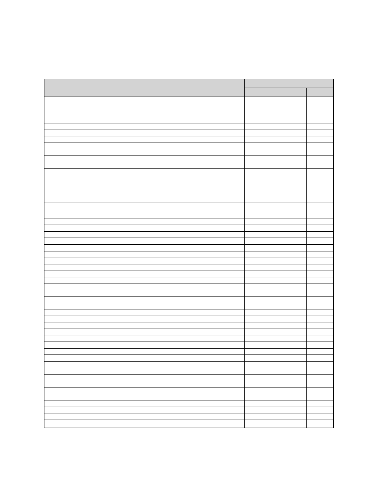
2.1 Technical data
Name
Nominal heat output range of central heating
80 °C Feed/60 °C Return
60 °C Feed/40 °C Return
50 °C Feed/30 °C Return
40 °C Feed/30 °C Return
Maximum output DHW
Maximum heating output
Minimum output
Category
SEDBUK Band
SAP Seasonal Efficiency
Required gas flow pressure (G20, Natural Gas)
Required gas flow pressure (G31, Propane)
Connection value (if necessary referred to storage tank charging/hot water preparation)
at 15 °C and 1013 mbar
Exhaust mass flow
at minimum thermal load (40 °C Feed/30 °C Return)
at maximum thermal load (80 °C Feed/60 °C Return)
Exhaust temperature
at minimum thermal load (40 °C Feed/30 °C Return)
at maximum thermal load (80 °C Feed/60 °C Return)
NOx class 5
Protection class IP X4D
Max. flow temperature 85 °C
Adjustable flow temperature (default setting: max. 75 °C) 30 - 85 °C
Permissible total excess pressure central heating 3.0 bar
Volume of water circulating (ΔT =20 K) 1204 l/h
Approximating condensation water volume at 50 °C Feed/30 °C Return 2.9 l/hr
Pump head 250 mbar
Minimum water flow < 0.1 l/min
Specific throughflow in 10 min (ΔT = 30 K) 204 l/10min
Permissible excess pressure water side 10 bar
Required connection pressure for max. throughflow quantity 1.3 bar
Required connection pressure for min. throughflow quantity 0.1 bar
Hot water temperature discharge 35 - 65 °C
Flue size (concentric) 60/100 mm
Flue approval category C
Pre-pressure 10 l expansion vessel 0.75 bar
Connections for heating flow and return 22 mm
Gas connection 22 mm
Diameter of the drain line for the safety valve heating (min.) 15 mm
Diameter of the drain line for the safety valve hot water (min.) 15 mm
Condensate drain (min. internal diameter drain) 19 mm
Dimensions (H x W x D) 720 x 440 x 597 mm
Primary water quantity 2.5 l
Supply voltage 230/50 V ~/Hz
Main PCB fuse (slow-blow) for main power supply 2 A
Electr. Power consumption 175 W
Standby power consumption 6.5 W
Layered storage tank capacity 15 l
Installation weight, just storage tank 17 kg
Installation weight, just combi unit 38 kg
Operating weight (with water) 62 kg
Table 2.1 Technical Data ecoTEC plus 937
ecoTEC plus 937
Combination unit Unit
12.0 - 28.0
12.3 - 28.9
12.7 - 29.7
12.9 - 30.3
37 kW
28 kW
12 kW
II2H3P
A
91.5 %
20 mbar
37 mbar
G20: 4.0
G31 : 2.94
5.7
17.1
40
70
, C
, C
, C
, C
, B
, B
kW
kW
kW
kW
G20 :m
G31 : kg/h
g/s
g/s
°C
°C
3
/h
Installation and maintenance instructions ecoTEC plus 0020031552_036
Page 7
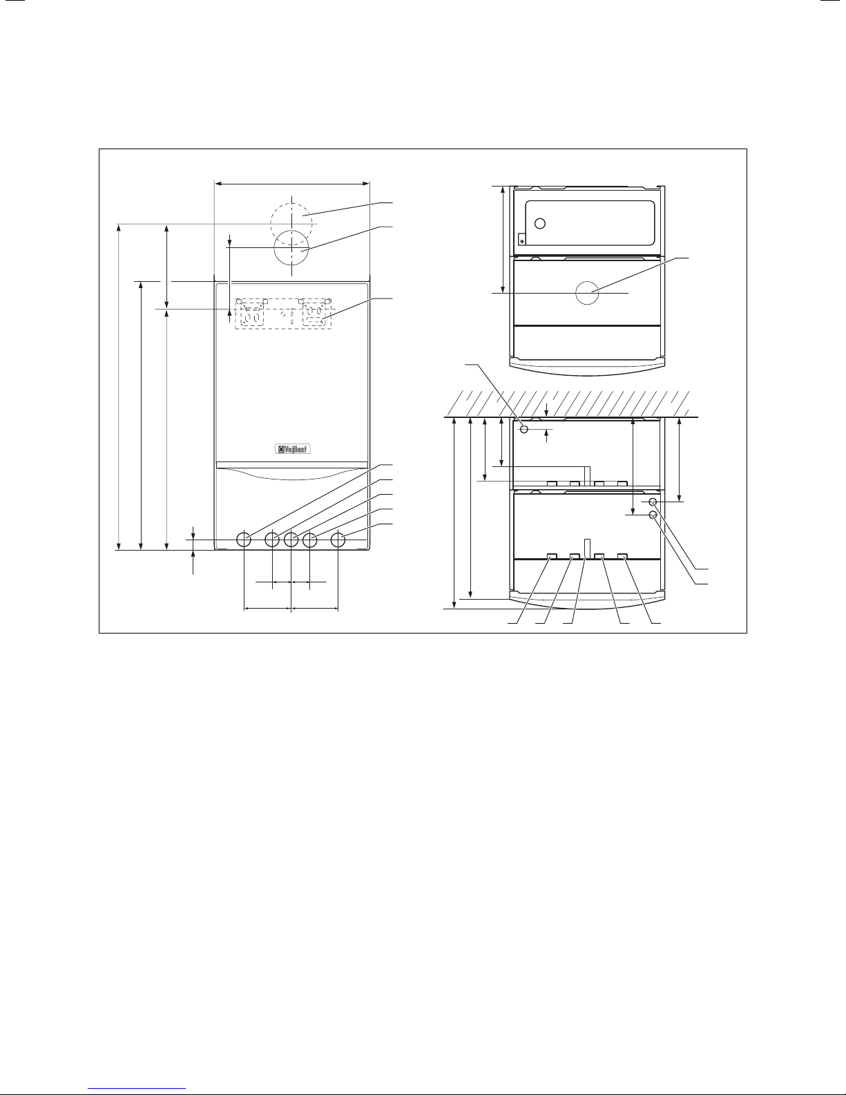
2.2 Dimensions
241
883
720
642
Unit description, data and dimensions 2
440
8
7
323
175
6
12
130
5
4
3
2
1
180
566
598
273
9
243
20
Fig. 2.1 Dimensions ecoTEC plus 937
1 Heating return pipe, Ø 22 mm
2 Cold water connection, Ø 15 mm
3 Gas connection Ø 22 mm
4 Hot water connection, Ø 15 mm
5 Heating flow pipe, Ø 22 mm
6 Hanging bracket
7 Flue hole - flue system 60/100
8 Flue hole - flue system 80/125
9 Flue duct connection
10 Condensate drain connection, Ø 19 mm
11 Heating system pressure relief valve connection, 15 mm
12 Layered storage tank pressure relief connection (flexible hose supplied)
35 35
100100
10
11
12345
7Installation and maintenance instructions ecoTEC plus 0020031552_03
Page 8
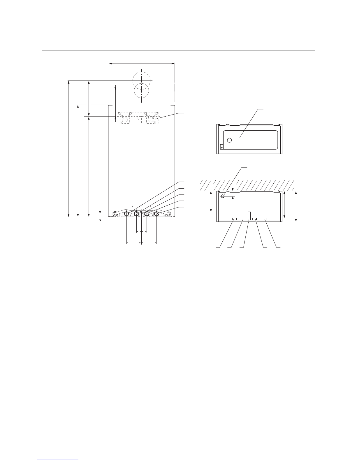
2 Unit description, data and dimensions
440
241
883
720
642
Fig. 2.2 Dimensions shift load storage tank
20
175
35
35
100100
6
5
4
3
2
130
1
8
7
180
198
12345
1 Heating return pipe, Ø 22 mm
2 Cold water connection, Ø 15 mm
3 Gas connection Ø 22 mm
4 Hot water connection, Ø 15 mm
5 Heating flow pipe, Ø 22 mm
6 Hanging bracket
7 Shift load storage tank pressure relief connection (flexible hose supplied)
8 Cover
Installation and maintenance instructions ecoTEC plus 0020031552_038
Page 9
Unit description, data and dimensions 2
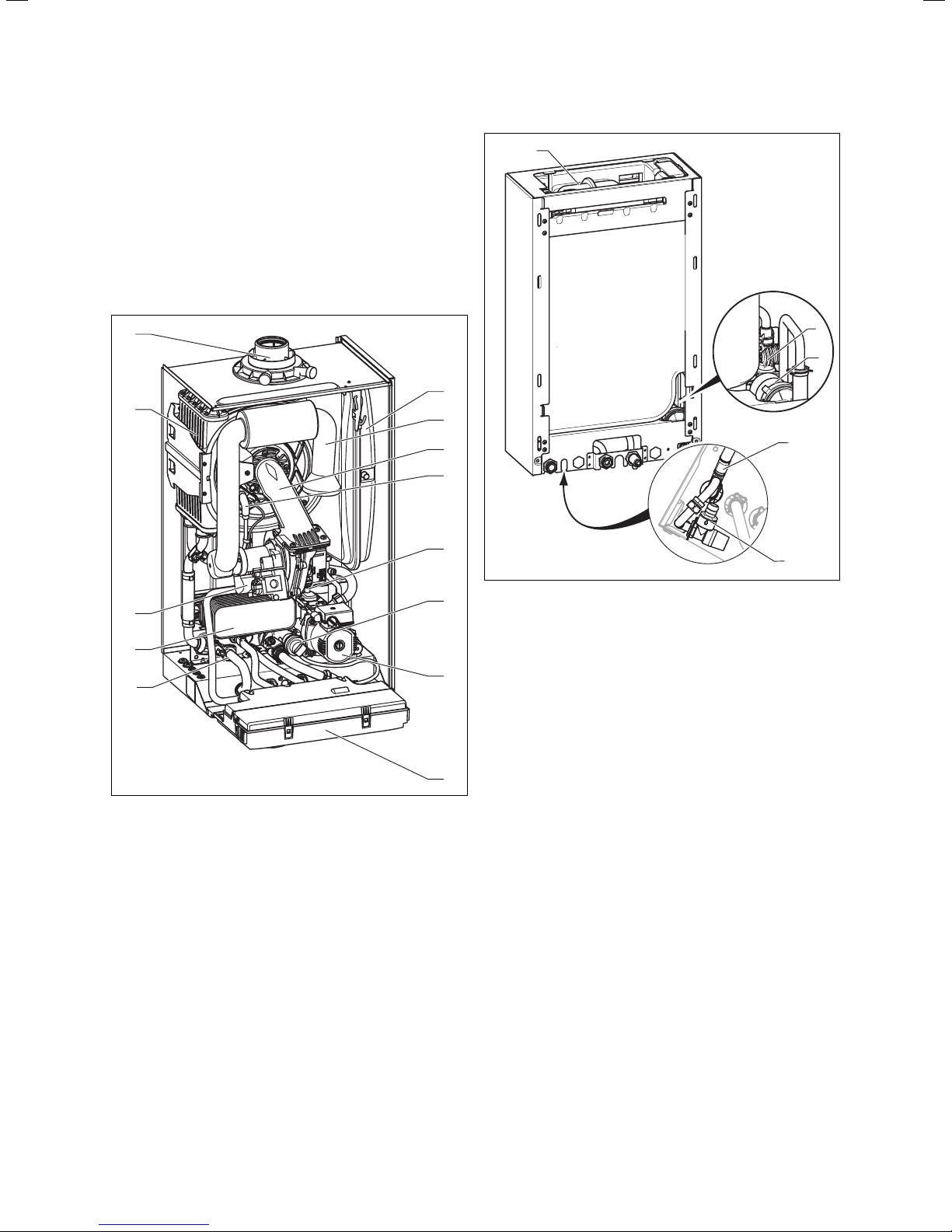
2.3 Structure and functional elements
The ecoTEC plus 937 consists of
– a modified combination boiler and
– a 15 litre shift load storage tank.
Mains cold water heated by the combi unit is fed to the
heat insulated storage tank by means of a modulating
storage tank charging pump.
The combi unit supplies the shift load storage tank with
electrical energy for the storage tank charging pump.
13
1
12
11
10
9
2
3
4
5
6
7
1
2
3
4
5
Fig. 2.4 Function elements shift load storage tank
1 Shift load storage tank expansion vessel
2 Aqua-Sensor
3 storage charging pump
4 NTC temperature sensor - hot water outlet
5 Storage tank pressure relief valve
Fig. 2.3 Function elements combi unit
1 Expansion vessel combi boiler
2 Air intake pipe
3 Compact thermal module
4 Ignition electrode
5 Fan
6 Diverter valve with built in automatic adjustable bypass
7 pump
8 Electronics box
9 Pressure sensor
10 Hot water heat exchanger
11 Gas valve
12 Heat exchanger
13 Connection flue duct
2.4 Identification plates
The identification plate of the ecoTEC plus 937 is located on the underside of the unit.
8
9Installation and maintenance instructions ecoTEC plus 0020031552_03
Page 10

2 Unit description, data and dimensions
2.5 Functional description
1
20
15
14
19
18
a
c
b
13
12
2
3
4
5
6
7
8
9
10
Fig. 2.5 Sequence diagram
1 Exhaust gas
2 Heat exchanger
3 Combustion chamber
4 Water condensate siphon
5 Expansion vessel
6 Operating display
7 Secondary heat exchanger
8 Automatic air vent
9 Pump
10 Pressure relief valve
11 Diverter valve
12 Gas valve
13 Fan
16
17
11
14 Compact thermal module
15 Shift load storage tank electronics
16 storage charging pump
17 Aqua-Sensor
18 Stainless steel storage tank
19 Storage tank insulation
20 Expansion vessel
NTC sensors shift load storage tank
a Storage tank sensor
b Infeed sensor SWT
c Storage tank charging sensor
Installation and maintenance instructions ecoTEC plus 0020031552_0310
Page 11

Unit description, data and dimensions 2
General requirements 3
The ecoTEC plus 937 is a fully-automatic wall-mounted
unit with condensing technology for central heating and
hot water preparation and with a shift load storage tank
for the storage of hot water.
Mains cold water heated by the combi boiler is fed to
the heat insulated storage tank by means of a modulating storage tank charging pump.
The provision of hot water takes place directly from the
combi boiler without the need for a copper cylinder, a
cold water tank or a supply and expansion vessel with
the corresponding pipework. The provision of hot water
has priority over the central heating.
The combi unit supplies the shift load storage tank with
electrical energy for the storage tank charging pump.
The combi unit is equipped with a warm start function
which keeps the heat exchanger hot so that hot water is
immediately available.
The temperature in the hot water heat exchanger is limited by the control system.
Fitting a water softener on the mains cold water inlet of
the combi boiler is not necessary. In regions with extremely hard water (greater than 300 mg/l of CaCO
however a water softener may still be fitted in order to
prevent the formation of scale build up in the water pipes.
The heating system can be filled using the filling devices
fitted to the ecoTEC plus combination boilers.
The ecoTEC plus 937 is be supplied for natural gas and
can be converted for propane gas with a conversion kit.
)
3
3 General requirements
3.1 Preliminary remarks for room sealed appliances
This appliance should only be installed in conjunction
with either a Vaillant flue system or an alternative approved system (details of flue approval categories can be
found in the technical section of the installation manual).
Install the flue system as detailed in the separate flue
installation instructions supplied with this boiler.
3.2 Related documents
The installation of the boiler must be in accordance with
the relevant requirements of Gas Safety (Installation
and Use) Regulations 1998, Health and Safety Document
No. 635 (The Electricity at Work Regulations 1989),
BS 7671 (IEE Wiring Regulations) and the Water Supply
(Water Fitting) Regulations 1999, or The Water Bylaws
2000 (Scotland). It should also be in accordance with
the relevant requirements of the Local Authority, Building Regulations, The Building Regulations (Scotland),
The Building Regulations (Northern Ireland) and the relevant recommendations of the following British Standards:
BS 6700: Services supplying water for domestic use
within buildings and their curtilages.
BS 6798: Specification for installation of gas fired boilers not exceeding 60 kW input.
BS 6891: Specification for installation of low pressure
gas pipework up to 28 mm (R1) in domestic premises
(2nd family gas).
BS 7593: Treatment of water in domestic hot water central heating systems. – Institute of Gas Engineers Publication IGE/UP7 Edition 2
BS 5482: Pt. 1 Domestic butane and propane gas burning installations.
IGE/UP1: Soundness testing and purging of industrial
and commercial gas installation.
IGE/UP2: Gas installation pipework, boosters and compressors on industrial and commercial premises.
IG/UP/7 Edition 2 „Gas installations in timber framed
and light steel framed buildings“
IGE/UP10. Installation of gas appliances in industrial and
commercial premises.
BS 6644: Installation of gas fired hot water boilers of
rated inputs between 60 kW and 2 MW (2nd and 3rd
family gases).
BS 5449: Forced circulation hot water central heating
systems for domestic premises. Note: only up to 45 kW.
BS 6880: Low temperature hot water heating systems
of output greater than 45 kW.
Part 1 Fundamental and design considerations.
Part 2 Selection of equipment.
Part 3 Installation, commissioning and maintenance.
BS 4814: Specification for: Expansion vessels using an
internal diaphragm, for sealed hot water heating systems.
BS 5440: Installation and maintenance of flues and ventilation for gas appliances of rated input not exceeding
70 kW net (1st, 2nd and 3rd family gases).
Part 1 Specification for installation of flues.
Part 2 Specification for installation and
maintenance of ventilation for gas appliances.
European installation directive
Caution!
a
Installation and maintenance of the unit may
only be undertaken by a competent person in
accordance with the "Gas Safety (Installation
and Use) Regulations 1998".
In IE the installation must comply with the current Version of I.S.813 ‘Domestic Gas Installations’ and the current Building Regulations. The
current ETCI Regulations for the installation of
electrical equipment must also be observed.
Caution!
To tighten or loosen bolts, only use suitable
open-ended spanners (do not use wrenches or
extensions etc.).
Improper use or unsuitable tools can cause damage, (such as gas or water leaks.)
11Installation and maintenance instructions ecoTEC plus 0020031552_03
Page 12
3 General requirements
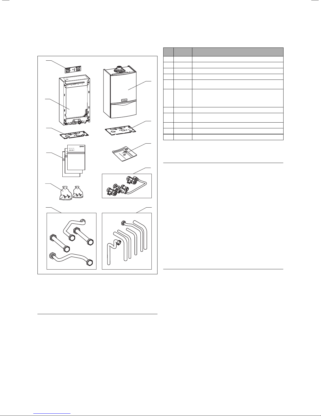
3.3 Scope of supply and accessories
1 1
10
9
8
7
6
Pos. Quantity Name
1 1 Combi boiler ecoTEC plus
2 1 Bottom cover ecoTEC plus
3 1 Installation template
4 4 Isolating valves and filling loop
1
56
65
7 2 Installation and connection accessories:
83
2
9 1 Bottom cover for shift load storage tank
10 1 Shift load storage tank
11 1 Hanging bracket
3
Table 3.1 Scope of supply and accessories
Connecting pipes (gas, heating, water, safety
valve)
Adapter set, consisting of connecting pipes between the shift load storage tank and the combi
boiler for gas, heating flow and return and water
flow and return
User, installation and service, flue installation manuals
3.4 Installation location
4
Note
h
When selecting the installation location observe
the regulations and recommendations for combi
boilers!
The installation location for the combi boiler and shift
load storage tank must permit proper connection of the
flue gas system to the combi boiler. In addition there
5
must be sufficient space for maintenance work and air
circulation around the combi boiler and the shift load
storage tank.
The Combi boiler and shift load storage tank can be
mounted together in any room you wish to choose.
In rooms with a bath or a shower, the special requirements of BS 7671 (IEE Regulations), the electro-technical
stipulations of the Building Standards (Scotland) Regulations and, in IE, the current issue of IS 813 and the current ETCI Stipulations must especially be observed.
Fig. 3.1 Scope of supply and accessories
The shift load storage tank and the combi boiler are
delivered pre-assembled in one packaging unit.
Check that all parts have been delivered undamaged
(see Fig. 3.1 and Table 3.1 ).
Note
h
At this stage do not yet remove the combi
boiler and the shift load storage tank from
the expanded polystyrene base to prevent any
damage.
Danger!
e
Danger of death by electric shock!
If a room-sealed combi boiler is installed in
a room with a bath or a shower, the electrical
switches and the boiler controller, which
operate at mains voltage, must be mounted
in locations where any person in the bath or
in the shower cannot reach them.
In the event of installation in unusual locations, special
provisions may have to be made. Detailed instructions
for this can be found in BS 5546 and in BS 6798.
The ecoTEC plus 937 must be mounted on a flat, vertical
wall which is sufficiently strong to hold the weight of
the shift load storage tank and the combi boiler.
It is possible to mount onto a wall made of flammable
material if the regulations of the Local Authority and
the legal building regulations are fulfilled. In this case
Installation and maintenance instructions ecoTEC plus 0020031552_0312
Page 13
General requirements 3
however, the unit would have to be mounted in a specially made enclosure. (You can also use an existing
cabinet or existing enclosure as long as it can be modified accordingly to suit the new application.) Further details concerning the fundamental characteristics when
modifying existing cabinets or enclosures, including the
requirements for ventilation, are described in BS 6798.
Note
h
If the boiler is to be installed in a half-timbered
house, the installation must be undertaken in
accordance with the Institute of Gas Engineers
Publication IG/UP/7 Edition 2 „Gas installations in timber framed and light steel framed
buildings“
Note
h
If the boiler is to be installed in an airing
cupboard it is not required to separate the
boiler with a non-combustible partition. However installation and servicing clearances must
be maintained, and the appliance kept clear of
any clothing.
Please note the following instructions before choosing
where to install the boiler:
Caution!
a
Danger of damage to the unit from the effects
of frost!
Do not install the shift load storage tank and
combi boiler in rooms with a danger of frost.
is an existing gas meter you must check that it is
suitable for the required gas rate.
Installation pipes should be fitted in accordance with
BS 6891. In IE in accordance with the current issue of
IS 813. The pipework between the gas meter and the
combi boiler must be of an appropriate size. Do not use
any pipes that are smaller than the connection to the
combi boiler (22 mm). The entire installation must be
checked for leaks and purged in accordance with BS 6891.
3.6 Flue pipe
Danger!
d
Vaillant appliances are only system-certified if
genuine Vaillant flue pipes are used. Only use
genuine Vaillant flue pipes. Malfunctions can
occur if you use other accessories. These may
result in damage and injury. You will find a list
of genuine flue pipes in the Vaillant installation
manual for flue pipes.
The CE mark is valid only if the appliance is
operated with Vaillant flue pipes.
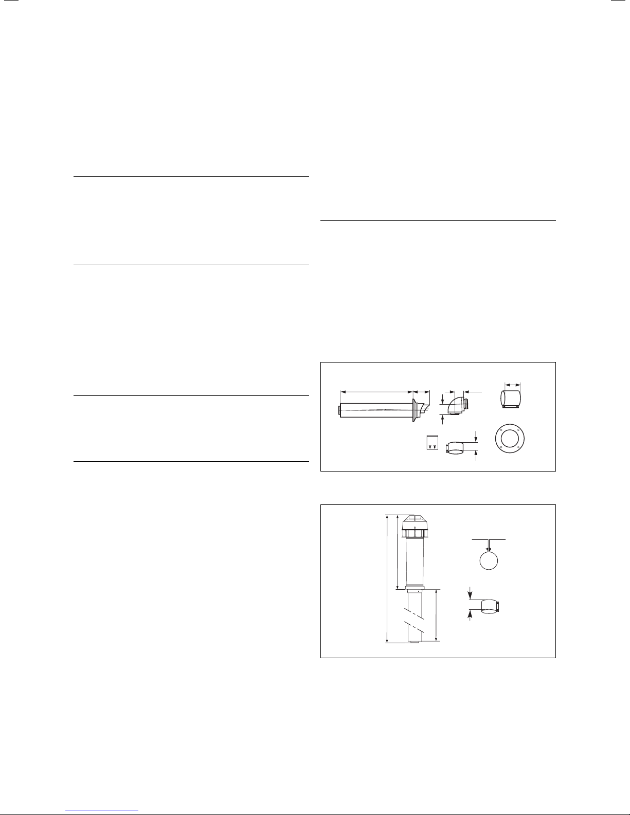
3.6.1 100 mm standard flue duct
667
87
65
74
48
30
Caution!
a
In rooms with aggressive vapours or dust the
combi boiler must be operated independent of
the ambient air.
Make sure that, when selecting the installation location
and when operating the unit, the combustion air is free
from chemical substances which contain fluorine, chlorine, sulphur etc. Sprays, solvents and cleaning agents,
paints, adhesives etc.can contain substances of this type
which can cause corrosion in the flue gas system, in the
worst case even if the unit is operated as an open vent
appliance. Particularly in hairdressing salons, lacquering
and finishing, cleaning facilities, the appliance must be
operated independent of the ambient air! Otherwise, a
separate installation room is required to guarantee that
the combustion air supply is free from the afore mentioned substances.
3.5 Gas supply
The gas provider must guarantee the availability of an
adequate gas supply. The connection of a gas meter in
the supply line is only permitted when carried out by the
gas provider and a company appointed by him. If there
Fig. 3.2 Item No. 303 933
542
1456
84
901
Fig. 3.3 Item No. 0020060570, 0020060571 and
0020065937 (60/100)
13Installation and maintenance instructions ecoTEC plus 0020031552_03
Page 14
3 General requirements
A 100 mm standard flue duct (Item No. 303 933) is
available. Further information can be obtained from the
installation instructions for the flue duct.
Extensions are available to increase this length to a
maximum of 5.5 m. 87° elbows and 45° bends are also
available to increase the flexibility during installation.
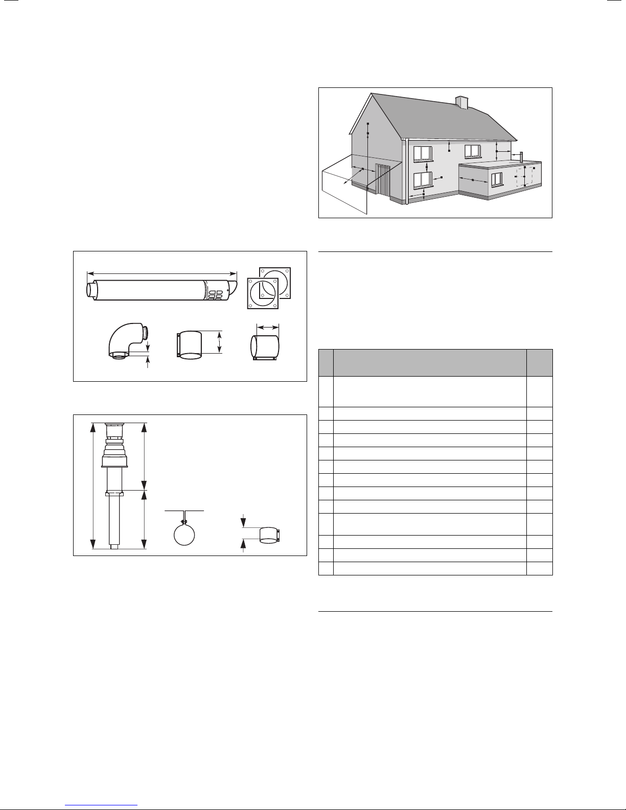
3.6.2 Optional 125 mm flue pipe
A concentric flue pipe having an outside diameter of
125 mm is available, which can be extended to a length
of up to 21 m.
You can also get a vertical system. Further information
can be obtained from the installation instructions for
the flue pipe.
A
G
F
J
H, I
Fig. 3.6: Flue termination
BCD
A
A
A
E
G
B
F
M
G
L
F
F
K
K
L
1103
70
70
15
Fig. 3.4 Item No. 303 209
650
1530
880
Fig. 3.5 Item No. 303 200 (80/125)
70
3.7 Flue termination
The following information applies to both flue pipe
systems.
a. The terminal position must be located in such a
position that any flammable gases can be freely
dissipated.
b. A plume of water vapour will sometimes be visible
from the flue terminal. Positions where this could
be a nuisance should be avoided.
c. If the terminal is less than 2 m above a balcony, the
ground or a flat roof that is accessible by persons,
a suitable terminal guard should be fitted (manufactured by Tower Flue Components, Tonbridge, TN9 1TB,
Model K3, plastic-coated).
Note
h
Vertical flue pipes must not terminate within
600 mm of an opening window, air vent or any
other ventilation opening.
The flue pipe must be fitted, or shielded, in such a way
that ignition or damage to sections of the building are
avoided.
Location of the junction mm
A Directly under or above an opening or the horizontal
to an opening, a hollow ventilation tile, an opening
window etc.
B Under gutters, soil pipes or drainpipes 75
C Unter eaves 200
D Under balconies 200
E From vertical drainpipes and down-pipes 25
F From external and internal corners 300
G Above the ground, a roof or a balcony 300
H Opposite another surface 600
I Opposite another termination 1200
J Next to an opening (e.g. a door, window) within a car-
port
K Vertically away from a junction on the same wall 1500
L Horizontally away from a junction on the same wall 300
M Distance away from an adjoining vertical flue pipe 500
Table 3.2 Position of the terminal in a fan-assisted concentric flue
300
1200
Note
h
In addition, the terminal should not be located
closer than 150 mm from an opening in the fabric
of the building formed for the purpose of accommodating a built-in element such as a window.
BS 5440–1: We recommend that the terminal of a
fan-assisted flue system be positioned as follows:
a) At least 2 m from an opening in the building directly
opposite, and
Installation and maintenance instructions ecoTEC plus 0020031552_0314
Page 15
General requirements 3
b) so that products of combustion are not directed to
discharge across a boundary.
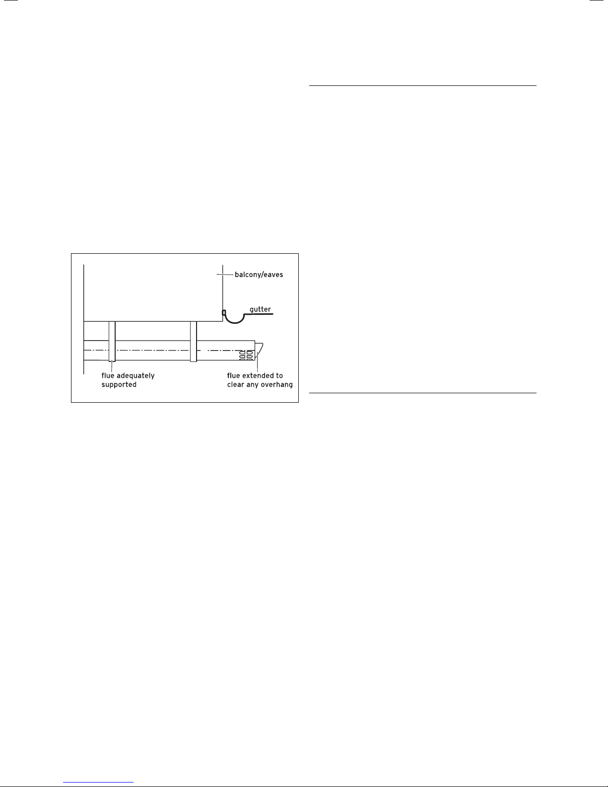
1) Dimensions B, C and D:
These dimensions can be reduced to 25 mm without
having a negative effect on the performance of the
boiler. In order to ensure that condensate plume does
not affect adjacent surfaces the terminal should be
extended as shown in Fig. 3.7.
2) Dimension F:
These dimensions can be reduced to 25 mm without
having a negative effect on the output of the combi
boiler. However in order to ensure that the condensate plume doe not affect adjacent surfaces a clearance of 300mm is preferred. For IE, recommendations are given in the current edition of IS813.
Danger!
e
Danger of death by electric shock!
The unit must be earthed.
3.10 System requirements
3.10.1 Water circulation system
Detailed recommendations concerning the water circulation system can be taken from BS 6798 and BS 5449,
Part 1 (for "Small Bore” and "Micro Bore” central heating systems). Pipework which does not form part of the
usable heating surface should be insulated to prevent
heat losses and possible freezing up, especially where
the pipes run through roof spaces and ventilated underfloor spaces. The drain connections must be located in
easily-accessible locations, so that draining the entire
system including the combi boiler and the hot water
system is possible. The drain connections should be at
least 1/2 " (BSP nominal size) and must be in accordance with BS 2879.
The combi boiler is suitable for Minibore and Microbore
Systems. Copper tubing in accordance with BS 2871
should be used for all water carrying pipework. All capillary joints in all Domestic Hot Water (DHW) pipework
must be made with lead free solder. When a new boiler
is to be fitted to an existing system, it is good practise
that the system is thoroughly flushed before the boiler
if installed in the system. See BS 7593 for full details.
Fig. 3.7 Flue termination under balcony/eaves
3.8 Air supply
Detailed recommendations for air supply are given in
BS 5440, Part 2.
It is not necessary to have an air vent in the room or
internal space in which the boiler is installed.
Ventilating a cabinet or enclosure
This appliance is highly efficient. As a consequence the
heat loss from the casing is very small. For cupboard or
compartment installations it is not necessary to provide
any high or low permanent air vents for cooling or ventilation purposes.
3.9 Electrical connection
In accordance with BS 7671 (IEE Wiring Regulations) and
any other local regulations which may apply, a 3 A
fused single phase AC supply (230 V, 50 Hz) must be
provided. In IE the current issue of the ETCI regulations
must be observed. The method of connection to the
mains electricity supply must provide a means of
completely isolating the boiler and ancillary controls.
Isolation is preferably by the use of a fused three pin
plug and unswitched shuttered socket outlet, both complying with the requirements of BS 1363. Alternatively,
a 3 A fused double pole switch with 3 mm contact separation on both poles may be used.
Caution!
a
To prevent the formation of deposits and
prevent serious damage to the appliance and
system, cleansers must be used carefully
following the cleanser manufacturers instructions and must be removed by thoroughly
flushing the system. Cleansers should only
be left in systems for a maximum of 24 hours.
Failure to thoroughly remove cleanser from a
system could result in damage to the appliance.
The cleaning must take place before fitting a new boiler
and in accordance with BS 7593. Recommendations for
use of system cleaning agents can be obtained from
Sentinel, Betz Dearborn Ltd. Widnes, Cheshire, WA8
8UD, Tel. 0151 420 9595, or Fernox, Alpha Fry Technologies, Tandem House, Marlow Way, Croydon, CR0 4XS,
Tel. 0870 8700362.
3.11.2 Filling and preparation of the heating system
The system can be filled using the incorporated filling
device. This connection must be removed again after
the filling process is complete. If the local Water Authority regulations do not allow temporary connection a
sealed system filler pump with break tank must be used.
The heating system will not be filled automatically from
the domestic hot water side. (Alternative methods of
filling sealed systems are given in BS 5449)
15Installation and maintenance instructions ecoTEC plus 0020031552_03
Page 16
3 General requirements
3.10.3 Pressure relief valve
The boiler is equipped with a pressure relief valve. This
safety device is required for all sealed central heating
systems, is preset to 3 bar and is fitted with a 15 mm
compression connection for the discharge pipe, whose
diameter must not be less than 15 mm. The pressure
relief valve must not be used for draining purposes.
3.10.4 Pressure gauge
The pressure gauge is fitted to the boiler in the factory
and indicates the pressure of the primary circuit, to
make filling and testing easier.
3.10.5 Heating circuit expansion vessel
The boiler of the ecoTEC series are equipped with a 10 litre
expansion vessel which is suitable for a sealed heating
system with a maximum water volume of 100 litres.
If the nominal capacity of the boiler expansion vessel is
not adequate for the heating system (e.g. when modernising old open systems) an additional expansion vessel
can be fitted outside the boiler. The pressure gauge
must be fitted in the return pipe, in accordance with
BS 5449: Part 1, as close as possible to the boiler.
In Table 3.5 you will find an overview of the required
size of an additional expansion vessel.
Vessel volume
(in l)
Initial system pressure (in bar) 1.0 1.5
Setting of the excess pressure valve (in bar) 3.0
Total water volume of the system (in l)
25 2.7 3.9
50 5.4 7.8
100 10.9 15.6
125 13.6 19.5
150 16.3 23.4
175 19.1 27.3
200 21.8 31.2
225 24.5 35.1
250 27.2 39.0
275 30.0 42.9
300 32.7 46.8
325 35.7 50.7
350 38.1 54.6
375 40.9 58.5
400 43.6 62.4
425 46.3 66.3
450 49.0 70.2
475 51.8 74.1
500 54.5 78.0
With other system volumes than shown above,
multiply the volume by the adjacent factors
0.109 0.156
3.10.6 Shift load storage tank expansion vessel
The shift load storage tank is fitted with a 1 litre expansion vessel.
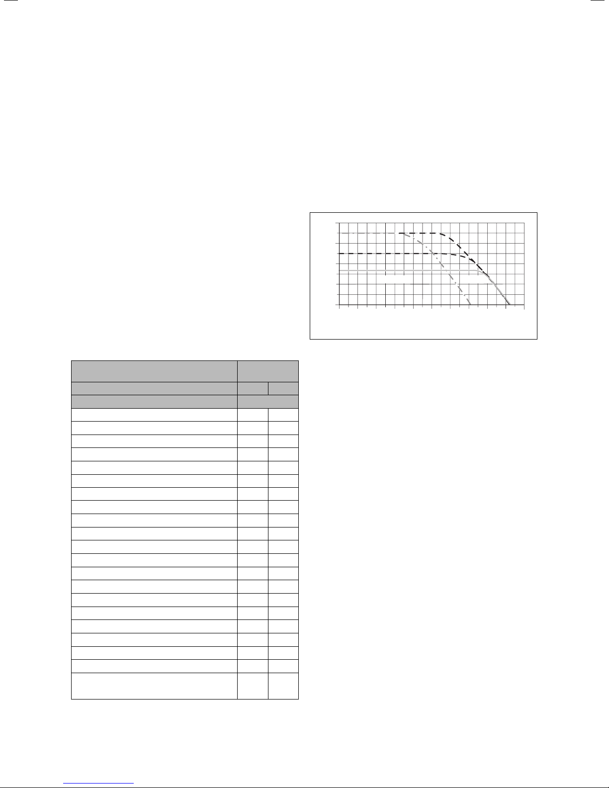
3.11 Details for the pumps
3.11.1 Circulation pump
The circulation pump is integrated in the combi boiler.
The remaining head of the pump with respect to the
bypass valve is shown in Fig. 3.8.
The operating mode of the 2-speed pump can be adjusted using diagnostic number d.19, see Section 8.1.2.
400
]
mbar
300
[
Lift
200
100
0
0 200 400 600 800 1000 1200 1600
Fig. 3.8 Technical data of the pump in the combi boiler
2. Step1. Step
18001400
2000
Volumeflow [l/h
]
3.11.2 Shift load storage tank circulation pump
The shift load storage tank is equipped with a maintenance-free charging pump.
3.12 System-Bypass
The boiler is fitted with an automatic system by-pass.
The installation can be used in systems with thermostatic radiator valves without the need for an additional
by-pass. The by-pass valve is adjustable, see Section 5.8.
3.13 Venting
The boiler is fitted with an automatic air vent. Other
measures need to be taken to allow the heating system
to be either automatically or manually vented during
filling and during commissioning.
3.14 Condensate siphonic trap
The boiler is fitted with a siphonic condensate trap
incorpaorating a water seal of 145 mm.
Table 3.3 Size of an additional expansion vessel
Installation and maintenance instructions ecoTEC plus 0020031552_0316
Page 17

Sequence of operations during installation 4
4 Sequence of operations during
installation
4.1 Transporting the appliance
Important:
a
With regards to the Manual Handling Operations,
1992 Regulations, the following lift operation
exceeds the recommended weight for a one man
lift.
General recommendations when handling
• Clear the route before attempting the lift.
• Ensure safe lifting techniques are used – keep back
straight – bend using legs.
• Keep load as close to body as possible. Do not twist –
reposition feet instead.
• If 2 persons performing lift, ensure co-ordinated
movements during lift.
• Avoid upper body/top heavy bending - do not lean
forward/sideways.
• Recommend wear suitable cut resistant gloves with
good grip to protect against sharp edges and ensure
good grip.
• Always use assistance if required.
Removal of carton from delivery van
• Recommend 2 person lift or 1 person with use of sack truck.
• If 1 person is performing lift, straddle the load, tilt and
place carton into position on truck.
• Recommend secure appliance onto truck with suitable
straps.
• Ensure safe lifting techniques are used – keep back
straight – bend using legs.
• Keep load as close to body as possible.
• If 2 persons performing lift, ensure co-ordinated
movements during lift.
• Always use assistance if required.
Carriage of carton from point of delivery to point of
installation – ground floor.
• Recommend 2 person lift or 1 person with use of sack truck.
• If 1 person is performing lift, straddle the load, tilt and
place carton into position on truck.
• Recommend secure appliance onto truck with suitable
straps.
• Ensure safe lifting techniques are used – keep back
straight – bend using legs.
• Keep load as close to body as possible.
• If 2 persons performing lift, ensure co-ordinated
movements during lift.
• Clear the route before attempting the lift.
• If removing boiler from truck straddle the load and tilt
forwards to facilitate secure grip.
• Ensure safe lifting techniques are used – keep back
straight – bend using legs.
• Do not twist – reposition feet instead.
• Take care to avoid trip hazards, slippery or wet
surfaces and climbing steps and stairs.
• Always use assistance if required.
Carriage of carton from point of delivery to point of
installation – first or higher floor, cellar.
• Recommend 2-person lift or 1 person with use of sack
truck.
• If 1 person is performing lift, straddle the load, tilt and
place carton into position on truck.
• Recommend secure appliance onto truck with suitable
straps.
• Ensure safe lifting techniques are used – keep back
straight – bend using legs.
• Keep load as close to body as possible.
• If 2 persons performing lift, ensure co-ordinated
movements during lift.
• Avoid upper body/top heavy bending - do not lean
forward/sideways.
• Clear the route before attempting the lift.
• If removing boiler from truck straddle the load and tilt
forwards to facilitate secure grip.
• Ensure safe lifting techniques are used – keep back
straight – bend using legs.
• Do not twist – reposition feet instead.
• Take care to avoid trip hazards, slippery or wet
surfaces and climbing steps and stairs.
• Always use assistance if required.
Carriage of carton from point of delivery to point
of installation – roofspace.
• Recommend 2-person lift.
• Ensure co-ordinated movements during lift.
• Avoid upper body/top heavy bending - do not lean
forward/sideways.
• Clear the route before attempting the lift.
• Take care to avoid trip hazards, slippery or wet
surfaces and climbing steps and stairs.
• When transferring appliance into roofspace,
recommend 1 person to be in roofspace to receive the
appliance and other person to be below to pass up
and support appliance.
• Ensure safe lifting techniques are used – keep back
straight – bend using legs.
• Keep load as close to body as possible.
• Always use assistance if required.
• It is assumed safe access, flooring and adequate
lighting are provided in the roof space.
• It is recommended a risk assessment of the roof space
area be carried out before moving the appliance into the
area to take into account access, stability of flooring, lighting and other factors, and appropriate measures taken.
Unpacking of appliance from carton.
• Recommend 2 persons unpack appliance from carton.
• Always keep working area clear.
• Recommend straps and open carton flaps, then remove
items from the top including the polystyrene packing
and remove carton by sliding up over the boiler.
17Installation and maintenance instructions ecoTEC plus 0020031552_03
Page 18

4 Sequence of operations during installation
• Ensure safe lifting techniques are used – keep back
straight – bend using legs.
• Keep load as close to body as possible.
• Always use assistance if required.
• Dispose of packaging in a responsible manner.
• Recommend wear suitable cut resistant gloves with
good grip to protect against sharp edges and ensure
good grip when handling appliance outside packaging.
Positioning of Appliance for Final Installation –
no obstructions.
• If appliance weight is over 25 kg always use 2 persons
to move where practical.
• Fit bracket securely onto wall before lifting appliance
into position.
• Obtain firm grip on front and sides of appliance, lift
upwards, ensure stable balance achieved and lift
upwards to position in place on bracket.
• Ensure safe lifting techniques are used – keep back
straight – bend using legs - when lifting load from
floor level.
• Do not twist – reposition feet instead.
• Keep boiler as close as possible to body throughout
lift to minimise strain on back.
• Ensure co-ordinated movements to ensure equal
spread of weight of load.
• Always use assistance if required.
• Recommend wear suitable cut resistant gloves with
good grip to protect against sharp edges and ensure
good grip when handling appliance.
Positioning of Appliance for Final Installation – above
worktop, foreseeable obstructions etc.
• If appliance weight is over 25 kg always use 2 persons
to move where practical.
• Fit bracket securely onto wall before lifting appliance
into position.
• Obtain firm grip on front and sides of appliance, lift
upwards, onto worktop if practicable.
• Ensure stable balance achieved and lift upwards to
position in place on bracket.
• If 2 persons positioning onto bracket obtain firm grip
at front and sides/base of boiler.
• Ensure coordinated movements during 2 person lifts
to ensure equal spread of weight of load.
• Ensure safe lifting techniques are used – keep back
straight – bend using legs - when lifting load from
floor level.
• Do not twist – reposition feet instead.
• Keep boiler as close as possible to body throughout
lift to minimise strain on back.
• Avoid upper body/top heavy bending - do not lean
forward/sideways.
• Always use assistance if required.
• Recommend wear suitable cut resistant gloves with
good grip to protect against sharp edges and ensure
good grip when handling appliance.
Positioning of Appliance for Final Installation –
withincompartment etc. restricting installation.
• If appliance weight is over 25 kg always use 2 persons
to move where practical.
• Fit bracket securely onto wall before lifting appliance
into position.
• Obtain firm grip on front and sides of appliance, lift
upwards, onto worktop if practicable.
• Ensure stable balance achieved and lift upwards to
drop into place onto bracket.
• If 2 persons positioning onto bracket obtain firm grip
at front and sides/base of boiler.
• Ensure coordinated movements during 2 person lifts
to ensure equal spread of weight of load.
• If 1 person positioning onto bracket recommend obtain
firm grip supporting base of boiler.
• Ensure safe lifting techniques are used – keep back
straight – bend using legs - when lifting load from
floor level.
• Do not twist – reposition feet instead.
• Keep boiler as close as possible to body throughout
lift to minimise strain on back.
• Always use assistance if required.
• Recommend wear suitable cut resistant gloves with
good grip to protect against sharp edges and ensure
good grip when handling appliance.
Positioning of Appliance for Final Installation –
in roof space restricting installation.
• If appliance weight is over 25 kg always use 2 persons
to move where practical.
• Obtain firm grip on front and sides of appliance, lift
upwards, ensure stable balance achieved and lift
upwards to drop into place onto bracket.
• If 2 persons positioning onto bracket obtain firm grip
at front and sides/base of boiler.
• Ensure co-ordinated movements during 2 person lifts
to ensure equal spread of weight of load.
• If 1 person positioning onto bracket recommend obtain
firm grip supporting base of boiler.
• Ensure safe lifting techniques are used - keep back
straight – bend using legs - when lifting load from
floor level.
• Do not twist – reposition feet instead.
• Keep boiler as close as possible to body throughout
lift to minimise strain on back.
• Always use assistance if required.
• Recommend wear suitable cut resistant gloves with
good grip to protect against sharp edges and ensure
good grip when handling appliance.
• It is recommended a risk assessment of the roof
space area be carried out before moving the appliance
into the area to take into account access, stability of
flooring, lighting and other factors, and appropriate
measures taken.
Installation and maintenance instructions ecoTEC plus 0020031552_0318
Page 19
Sequence of operations during installation 4
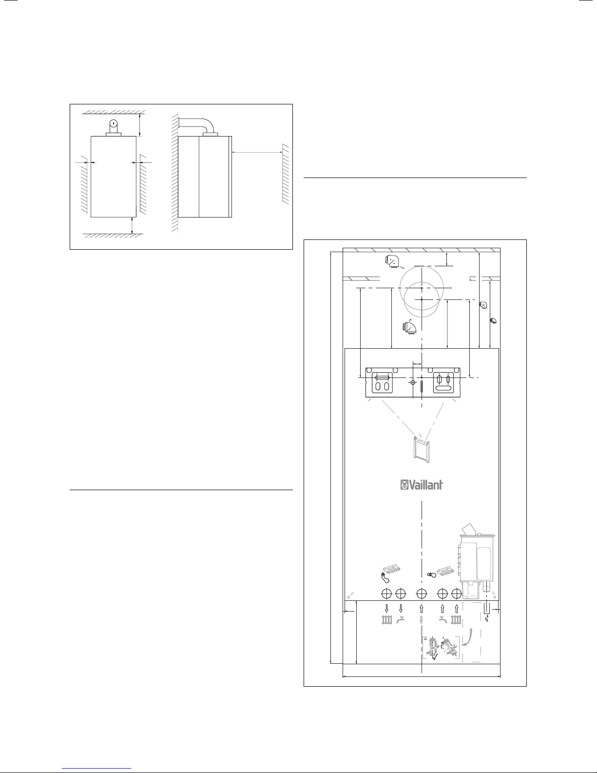
4.2 Required minimum gaps/assembly clearances
min
165/246
min 5
Fig. 4.1 Distances during installation (dimensions in mm)
min 5
min 180
min 500
The combination of units must be installed on a flat
vertical wall which is large enough for the shift load
storage tank with mounted combi boiler, including the
required minimum clearances and space allowances for
installation. The required minimum clearances during
installation can be taken from Fig. 4.1.
The minimum clearances and installation clearances are
shown on the installation template. They are:
– 5 mm on each side of the unit combination
– 180 mm underneath the unit combination
– 165 mm above the boiler if using a flue pipe of 100 mm
outside diameter
– 246 mm above the boiler if using a flue pipe of
125 mm outside diameter
– 500 mm in front of the unit combination to permit
easy access for service work.
Please note that, under the unit combination, there
should be adequate space to position the drain pipes via
a drain funnel. The drain must be visible!
Further information concerning the installation location
of the combi boiler can be found in the Section "Installation Location".
4.3 Unpacking the equipment
First cut through the two plastic straps when unpacking
the units. Then open the box and lift the top section of
the polystyrene off. Lift the box upwards.
Note
h
Please take care that the white surface of the
units is not damaged.
4.4 Using the installation template
40
80/125
(Art.-Nr. 303210)
276 ( )
195 ( )
173
256
A
1176
60/100
(Art.-Nr. 303910)
25
A
140
80/125
60/100
223
A
Note
h
If the boiler is to be installed in a timber framed
building, it should be fitted in accordance with
IG/UP/7 Edition 2 „Gas installations in timber
framed and light steel framed buildings“.
4.2.1 Selecting the location for the shift load
storage tank and combination boiler
The installation location for the shift load storage tank
and the combi boiler should be selected so that:
– there is adequate room around the boiler for service
and maintenance work
– the flue pipe of the combi boiler can operate properly
i.e. the location of the terminal of the flue pipe is
located in accordance with these instructions and the
flue pipe is installed in accordance with the installation
instructions for the flue pipe provided
– all the required pipework including the pressure relief
valve and the condensate drain can be fitted.
A
5
180
Fig. 4.2 Assembly template
A
5
0020039975_00 10 2006
450
19Installation and maintenance instructions ecoTEC plus 0020031552_03
Page 20
4 Sequence of operations during installation
Use the template provided for the installation (see
Fig. 4.2).
The template shows the following:
the position of the fixing holes for the hanging bracket,
– the position of the connections.
– the position of the hole in the wall for the flue pipe.
• line the installation template up vertically and fix the
template to the wall.
• mark the position of the fixing holes for the hanging
bracket,
• drill 2 holes Ø 10 mm in the wall for the hanging bracket.
Note
h
Please take the total weight of the unit
combination and the load capacity of the wall
into account.
If necessary drill alternative fixing holes. If
necessary use alternative fixing materials.
4.5 Flue exit
• If using rear flue mark the position of the air/flue duct
and its circumference.
• Remove the assembly template from the wall.
• If necessary cut the aperture in the wall for the flue pipe.
Other flue options
Instructions concerning other flue pipe systems, for
example, vertical flues, flue pipes to the side of the
boiler and the use of additional elbows etc. are listed in
the installation instructions for the flue pipe included
with the combi boiler.
• Fix the hanging bracket (1) to the wall using the plugs
and screws (2) provided with the appliance.
• Lift the shift load storage tank out of the packaging
(see Section 3.4).
• Lift the shift load storage tank (3) onto the wall so
that it is located slightly above the hanging bracket (1).
• Slowly lower the shift load storage tank onto the
hanging bracket so that the installation carrier on the
rear of the unit fully engages in the hanging bracket.
Note
h
If the appliance is to be fitted in a timber
framed building ensure that the hanging bracket is secured to a substantial part of the timber
frame capable of taking the full weight of the
appliance.
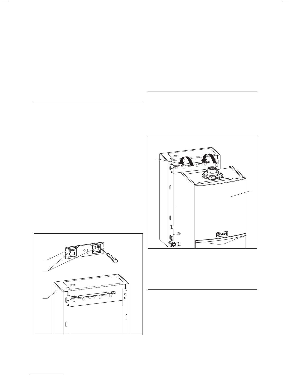
4.8 Mounting the combination boiler
1
2
4.6 Installation of the flue gas system
• Install the flue gas system (observe the separate
installation instructions for the flue pipe).
4.7 Fitting the appliance hanging bracket
1
2
3
Fig. 4.3 Shift load storage tank with hanging bracket
Fig. 4.4 Mounting the combi boiler on the shift load storage tank
• Lift the combi boiler out of the packaging (see Section
3.4).
• Lift the combi boiler (2) onto the shift load storage
tank so that it is located slightly above the shift load
storage tank (1).
Note
h
Lift the combi boiler at both sides of the base.
• Lower the combi boiler slowly onto the hanging bracket on the shift load storage tank so that the installation
carrier on the rear of the combi boiler fully engages in
the hanging bracket on the shift load storage tank.
Installation and maintenance instructions ecoTEC plus 0020031552_0320
Page 21

Sequence of operations during installation 4
4.9 Removing the front case
2
1
Fig. 4.5 Removing/fixing the front case
Proceed as follows to remove the front cladding:
• Release the screw (1) on the base of the unit.
• Push the two retaining clips (2) on the base of the
unit inwards until the front case releases.
• Hold the front case by the bottom edge, pull forwards
and remove the front case from the unit.
4.10 General instructions concerning the heating
system
Caution!
a
Danger of leaks by improper installation!
Ensure a stress-relief assembly of the gas
pipes.
Caution!
a
Danger of damage to units and system!
The electronic gas valve may be tested for
leakage only with a maximum pressure of
150 mbar!
At higher testing pressures there is a danger
that the gas fitting could be damaged.
Caution!
a
Danger of damage to the gas isolator valves by
heat transmission!
If the final connections to the combi boiler are
made using soldered pipe connections, you
must be particularly careful not to damage the
gas isolator valves by heat transfer.
2
1
Caution!
a
Clean the heating system thoroughly before
connecting the appliance!
This will remove small particles such as solder
residues, ash, hemp, putty, rust, dirt particles
and similar substances from the pipework.
Otherwise there is a danger that these particles
can deposit in the appliance and cause damage.
Note
h
The heating system is fitted with an expansion
tank (10 l/0.75 bar).
• Before connecting the unit, make sure that this volume
is adequate. Otherwise the installation must be fitted
with an additional expansion vessel (see Section 3.11.6).
4.11 Gas connection
Danger!
d
Danger of death by gas escapes if the installation is not properly carried out!
The gas connection must only be made by
a competent person (e.g. CORGI registered).
The legal directives and local regulations for
the gas supply companies must be observed.
3
4
1
5
6
2
Fig. 4.6 Gas connection
Proceed as follows for gas connection:
• Remove the gas connection pipe elbow (2) and gas
isolator valve (1) from the packaging.
• Push the union nut (3) and the olive (4) onto the gas
pipe which protrudes from the combi boiler.
• Push the gas isolator valve (1) onto the gas pipe which
protrudes from the combi boiler up to the stop.
• Pull the union nut (3) with the olive (4) towards the
gas isolator valve. Tighten the union nut hand tight.
• Push the union nut (6) and the olive (5) onto the gas
connection pipe elbow (2).
• Push the gas connection pipe elbow (2) into the gas
isolator valve (1) up to the stop.
21Installation and maintenance instructions ecoTEC plus 0020031552_03
Page 22

4 Sequence of operations during installation
• Pull the union nut (6) with the olive (5) towards the
gas isolator valve. Tighten the union nut hand tight.
• The diameter of the pre-formed copper pipe (2) is
22 mm. Connect this pipe to a gas supply pipe having
a diameter of not less than 22 mm.
Note
h
The gas supply pipework must be of sufficient
size so that, at maximum output, a gas pressure of 20 mbar is available at the input to the
combi boiler.
• Tighten all connections.
• Purge the gas pipe before commissioning.
• Check the gas connection for leaks using leak-detecting
spray.
4.12 Cold water supply and hot water outlet
Caution!
a
Ensure stress-free assembly of the connection
pipework to avoid leakages!
Caution!
Danger of damage to the gas isolator valves by
heat transfer!
If the final connections to the combi boiler are
made using soldered pipe connections, you
must be particularly careful not to damage the
gas isolator valves by heat transfer.
• Insert the fibre seal (1) and screw the cold water isolating valve (2) to the cold water connection of the
shift load storage tank.
• Push the union nut (4) with the inserted olive (3) onto
the copper tail (5) included with the combi boiler. The
diameter of this pipe is 15 mm.
• Insert the copper tail into the cold water isolating valve
up to the stop. Tighten the union nuts in this position.
• Insert the fibre seal (7) and screw the copper tail (6)
which is included with the storage tank module, to the
hot water connection on the unit. The diameter of this
pipe is 15 mm.
• Fit the handle for the filling loop to the cold water
stop valve (2) with a countersunk screw.
4.13 Piping between shift load storage tank and
combination boiler
1
3
4
2
7
6
1
2
3
4
5
Fig. 4.7 Installing the cold water and hot water connections
Note
h
Flush all foreign matter from the mains supply
before connecting to the appliance.
• Remove the two copper tails (5, 6) for water connection,
the cold water isolating valve (2) and the union nut
(4), olive (3) and fibre seals (1, 7) from the packaging.
Fig 4.8 Piping between shift load storage tank and combina-
tion boiler
• Remove the pipe sections (1), (2), (3) and (4) with the
associated fibre seals from the box of accessories of
the shift load storage tank.
• Fit the formed pipe and straight pipe sections in the
correct sequence.
Note
h
The formed pipes (1) and (2) must be fitted first.
4.14 Flow and return heating connections
Caution!
a
Ensure stress-free assembly of the connection
pipework to avoid leakages!
Caution!
a
Danger of damage to the stop valves by heat
transfer!
If the final connections to the combi boiler
are made using soldered pipe connections, you
must be particularly careful not to damage the
stop valves by heat transfer.
Installation and maintenance instructions ecoTEC plus 0020031552_0322
Page 23

Note
h
Before connecting the heating circuit to the
combi boiler all pipework and radiators must
be thoroughly flushed out to remove all contaminants.
13
10
9
Sequence of operations during installation 4
1
2
Ø max. 22 mm
3
8
7
6
12
11
Fig. 4.9 Flow and return heating connections
4
5
• Remove the stop valves with union nuts, olives and
fibre seals from the box of accessories for the combi
boiler.
• Insert the fibre seal (1) and screw the stop valve (2)
onto the return pipe connection on the combi boiler.
• Insert the fibre seal (10) and screw the stop valve (9)
with the fitted flexible hose (13) onto the flow connection of the combi boiler.
• Fit the O-ring seal (12) to the non-return valve (11).
Note
h
Lay the filling loop hose (13) above the pipework elbows.
• Push the union nuts (4) and (7) with olives (3) and (8)
onto the pre-shaped 22 mm pipes (5) and (6).
• Push the pipes (5) and (6) into the stop valves up to
the stop. Tighten the union nuts in this position.
• Fit the handle for the filling loop to the cold water
stop valve (9) with a countersunk screw.
Caution!
a
Please note that, when fitting a low loss header
the diameter of the connection lines between
the unit and the diverter must not be greater
than 22 mm.
Fig. 4.10 Diameter of the connection lines when using a low
loss header
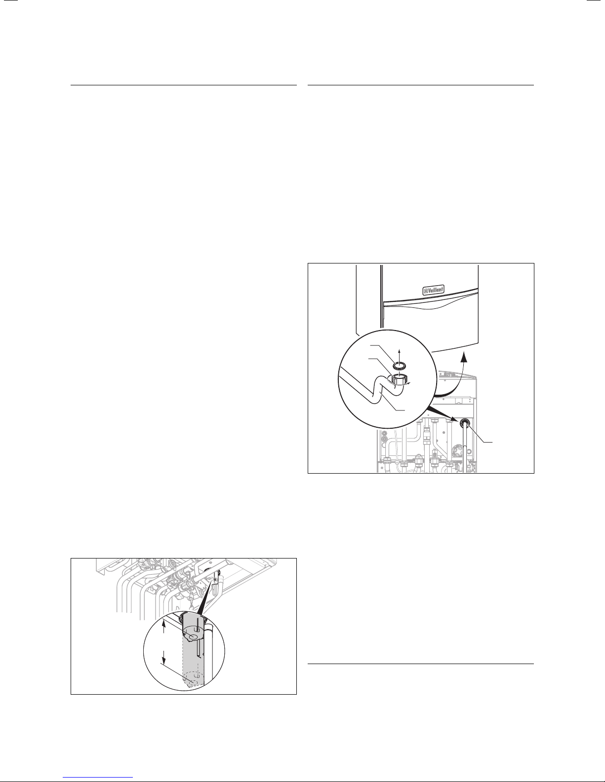
4.15 Condensate drain
The combi boiler is equipped with a condensate siphon.
(The filling height is 145 mm.) The siphon collects the
condensate in a vessel with a capacity of approx. 200 ml
and feeds the entire contents to the drain pipe. This
minimises the risk of the drain pipe freezing up.
1
2
4
6
3
a
Fig. 4.11 Installing the condensate drain
3
b
5
c
7
d
• Connect the condensate drain (1) of the boiler to
a condensate drain pipe (2) which has a minimum
internal diameter of 19 mm (22 mm outside diameter
for all external pipes) and which is made from an
acid-resistant material (e.g. plastic overflow pipe).
Note
h
The accessories for the storage tank include a
corrugated hose for draining the condensate.
23Installation and maintenance instructions ecoTEC plus 0020031552_03
Page 24
4 Sequence of operations during installation
Note
h
The drain pipe connected to the condensate
drain of the combi boiler must have a constant
gradient (45 mm per metre) and should be
installed and terminate within the building to
prevent the possibility of freezing up.
The condensate drain pipe must terminate in a suitable
location, e.g.:
a)
preferably the discharge pipe should run and termi-
nate internally to the house soil and vent stack
(at least 450 mm above the invert of the stack). A
trap giving a water seal of at least 75 mm (3) (built
into the boiler) should be incorporated into the pipe
run, and there must be an air break (4) in the discharge pipe upstream of the trap. The connection to
the stack should not be made in a way that could
cause cross flow into any other branch pipe, or from
that branch pipe into the condensate drainpipe. This
can be achieved by maintaining an offset between
branch pipes of at least 110 mm on a 100 mm diameter stack and 250 mm on a 150 mm diameter stack.
connecting into the internal discharge branch (e.g.
b)
sink waste or washing machine) with an external termination, the condensate discharge pipe should have
a minimum diameter of 22 mm with no length restriction and should incorporate a trap with a 75 mm (3)
(built into the boiler) seal. The connection should
preferably be made down stream of the sink waste
trap. If the connection is only possible upstream, then
an air break is needed between the two traps. This is
normally provided by the sink waste.
c)
terminating in a gully (5) below grid level (6) and
above the water level. The external pipe length
should be kept as short as possible to minimise the
risk of freezing and should not be more than 3 m.
at a condensate absorption point (soakaway) (7). The
d)
external pipe length should not be more than 3 m.
Danger!
d
Danger of poisoning!
In order to prevent exhaust gases from escaping from the combi boiler via the siphon, the
siphon must be filled with water before the unit
is switched on.
The discharge pipes must therefore be installed
in such a way that they do not cause an obstruction and sufficient clearance exists to
allow access to the condensate siphon.
There must be a minimum clearance of 180mm below
the siphon for access.
4.16 Installing the pressure relief discharge
pipework
1
2
3
4
Fig. 4.13 Installing the discharge pipe
Further information can be obtained from "BS 6798
Specification for installation of gas–fired boilers of rated
input not exceeding 70 kW net“. The condensate siphon
must be filled with water as described in Section 5.6 before the combi boiler is commissioned.
min.
180
Fig. 4.12 Installation space condensate siphon
The pressure relief for the heating system is integrated
into the boiler.
• Remove the discharge pipe with union nut and rubber
seal from the box of accessories for the shift load
storage tank.
• Insert the rubber seal (1) into the union nut (2) and
screw the discharge (3) onto the pressure relief
valve (4).
• The discharge pipework should be as short as possible
with a continuous fall from the appliance.
• The discharge pipe should terminate in such a way
that nobody can be injured and no cable or other electrical components can be damaged if water or steam is
discharged. Please note that the end of the discharge
pipe must be visible.
Note
h
We recommend that the discharge pipe for the
pressure relief valve is not shortened.
Installation and maintenance instructions ecoTEC plus 0020031552_0324
Page 25

Sequence of operations during installation 4
4.17 Storage tank pressure relief discharge pipework
1
2
Fig. 4.14 Storage tank pressure relief discharge pipe connection
The safety valve for the hot water system is integrated
in the shift load storage tank.
• Remove the flexible drain hose from the box of acces-
sories for the shift load storage tank.
• Push the drain hose (1) onto the safety valve (2).
The end of the drain hose can be directed via an open
connection to a tundish and terminated in a similar
manner to the boiler pressure relief discharge pipe.
4.18 Connecting the flue system to the combination boiler
• Refer to the separate air/flue duct installation instruc-
tions included with the appliance.
ration at all poles is at least 3 mm and which supplies
only the appliance and controls). The connection must
permit complete isolation of the appliance and its connected controller from the mains supply. It should be
easily accessible and be located in the proximity of the
combi boiler. Use a three core flexible cable in accordance
with BS 6500, Tables 6, 8 or 16 (3 x 0.75 to 3 x 1.5 mm
Danger!
e
Danger of death by electric shock!
The unit must be earthed.
Danger!
e
Danger of death by electric shock!
The power connections L and N continue to be
under power when the main switch of the combi
boiler is switched off.
Caution!
a
Danger of damage to the equipment!
Do not connect mains 230 V power to the terminals 7-8-9 or eBUS (+, -).
Note
h
Ensure that all wiring passes through the cable
clamps in the rear of the control box and are
securely fixed.
• Check that when connecting the mains wiring that the
current carrying conductors become taut before the
earth conductor should the supply cable slip from the
cable clamp.
4.19.2 Connecting shift load storage tank
2
).
4.19 Electrical connection
4.19.1 General requirements
Danger!
e
Risk of fatal electric shock from touching live
connections!
Before working on the appliance, turn off the power
supply and secure against restart! All work on the
electrical system should be carried out by a competent person and must be in accordance with
BS 7671 (IEE Regulations). In the Irish Republic
the current issue of the ETCI Regulations (ElectroTechnical Council for Ireland) must be observed.
Caution!
a
For the electrical connection observe the relevant
installation instructions for the ecoTEC combi
boilers and the country-specific regulations.
The appliance is designed for connection to 230 V,
~ 50 Hz supply with a 3 A rating. Connection to the
mains supply shall be made via a fused 3 pin plug to an
unswitched shuttered, and should comply with BS 1363.
(Alternatively the connection can also be carried out
with a 3 A fused two-pole isolator, whose contact sepa-
1
2
X31
Fig. 4.15 Opening the electronics box
X12
25Installation and maintenance instructions ecoTEC plus 0020031552_03
Page 26
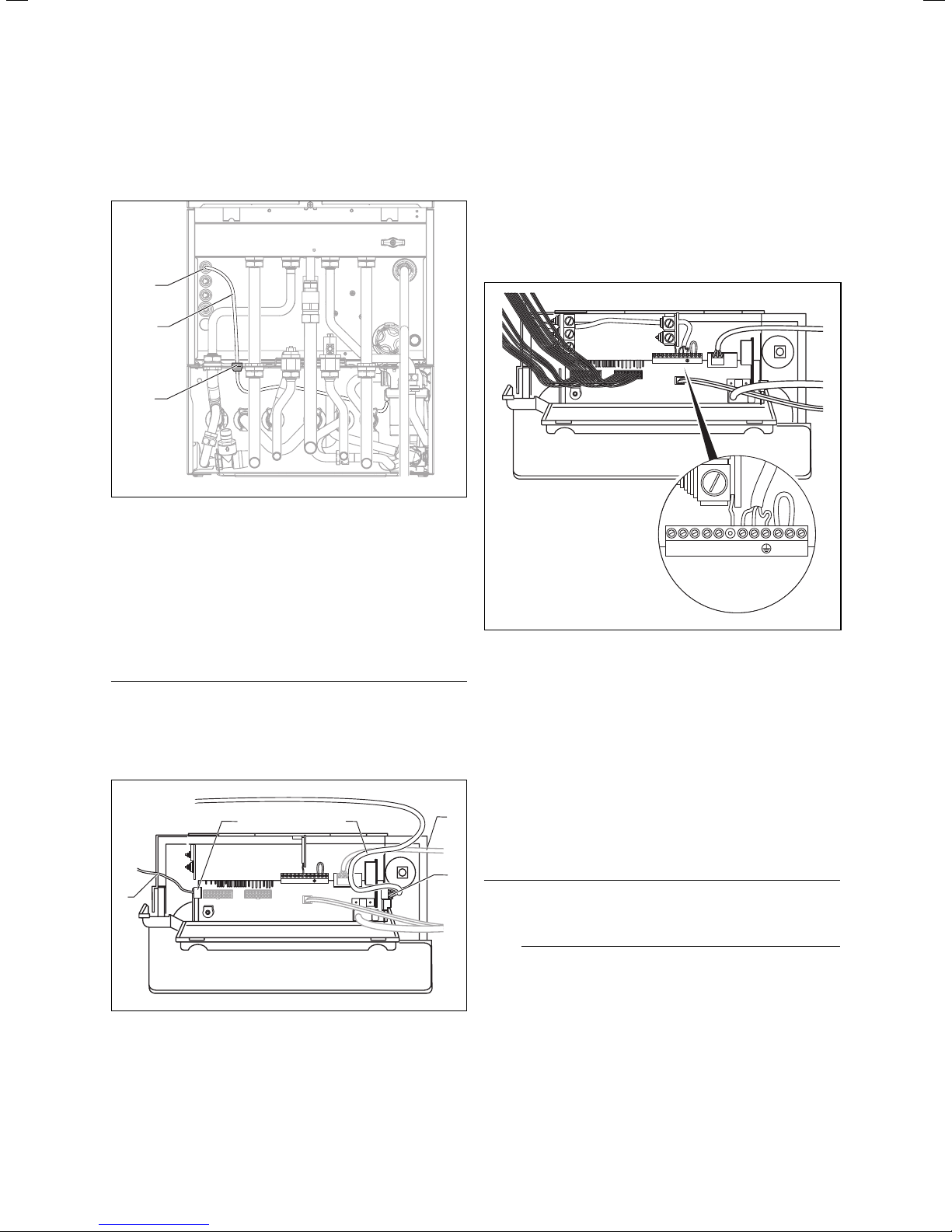
-+789 LN 345
4 Sequence of operations during installation
• Pull the electronics box forward and lower.
• Unclip the back cover of the electronics box and lift
the cover upwards to reveal the connections.
1
2
3
Fig. 4.16 Cable run on the underside of the unit
• Feed the wiring harness (2) of the shift load storage
tank with the grommets (3) through the cable entries
provided on the shift load storage tank and on the
combi boiler.
On the combi boiler use the cable entry at the very
front (1).
• Fix the grommets to the cable entries using the spring
clamps provided.
Caution!
a
Danger of cable damage!
Observe the routing of the cable!
The cables must not touch hot unit components!
2
3
4
• Run the sensor cable (1) with plug X31 to the printed
circuit board.
• Push the flat connector X31 onto the plug socket X31
(2) (left-hand side of the printed circuit board).
• Fix the cable (4) in the electronics box via the cable
clamps.
4.19.3 Connection the power supply
-+789 LN 345
Fig. 4.18 Connecting the power supply
• Run the flex through the cable entries provided in the
combi boiler and in the electronics box and tighten the
cable clamps.
• Connect the flex to terminals L and N and the earth
connection of the terminal block.
Green-yellow wire (earth) Boiler connection
earth symbol
Blue wire (neutral) Boiler connection N
1
Fig. 4.17 Cable routing in the electronics box
X31
-+789 LN 345
• Run the pump cable X12 (3) outside the electronics box.
• Push the plug X12 of the pump cable onto the plug
socket X12 (5) on the printed circuit board.
Brown wire (live) Boiler connection L
X12
5
Note
h
Do not connect power to the terminals 7-8-9 or
eBUS (+, -).
Note
Make sure that the cables are securely fixed in
the terminal blocks.
• Refit the electronics box cover by pushing into place
until it clips back into position ensuring all wires are
not trapped or pinched.
• Lift the electronics box up and secure.
Installation and maintenance instructions ecoTEC plus 0020031552_0326
Page 27

4.19.4 Wiring diagrams
Sequence of operations during installation 4
Shift load storage tank connection
Shift load storage tank pump connection
Burner cable harness
Accessory module connection
Diagnosis via eBUS,
vrnetDIALOG
External
sensor
external feed or return
line sensor
Wiring harness hydraulics
Connection for
external eBUS controller
Room thermostat 24 V:
Connection 7, 8 und 9
No bi-directional interface
(only analogue)
Mains connection 230 V/50 Hz
Room thermostat 230 V/50 Hz
(Remove bridge when connecting)
Heating pump
2 speed pump (plug with 5 pins)
Fuse 2 A, slow-acting
Igniter
Attention:
Do not connect
mains voltage
Danger of destroying
the electronics!
Fig. 4.19 Wiring diagram electronics box
Shift load storage tank
pump connection 230 V
27Installation and maintenance instructions ecoTEC plus 0020031552_03
Page 28

4 Sequence of operations during installation
Flow temperature
sensor (NTC)
X 20/5 red
X 20/7 black
X 20/8 blue
X 20/7 black
Gas valve
X 2/9 black
X 2/11 red
X 2/12 green
Return temperature
sensor (NTC)
Thermal fuse
X 20/18 red (24 VDC)
X 20/9 blue (Erde)
Water pressure sensor
Ignition electrode
X 20/13 black
X 20/12 black
Fa n
Plug
connection
X 20/16 blue (Earth)
X 20/4 grey (PWM)
X 20/3 black (Hall-Signal)
X 20/17 red (24 VDC)
X 2/16 black A
X 2/7 pink B
X 2/15 brown C
X 2/8 blue D
Diverter valve
Pump
X 2/3 red (+ 5V)
X 2/2 black (Earth)
X 2/6 Green (Signal)
X 20
X31
Electronics box
X40
X 2
X41
— +
BUS
X 2/4 orange
X 2/10 black
X 2/5 violet (Signal)
X 2/1 black
7 8 9
24V
L N 3
230V
4 5
Plate
heat exchanger
(NTC)
Hot water
outlet (NTC)
X12
Fig. 4.20 Wiring diagram combi boiler
Installation and maintenance instructions ecoTEC plus 0020031552_0328
Page 29

Sequence of operations during installation 4
Shift load storage tank electronics
X 1/3 Violet
X 1/1 Black
X 1/4 orange
X 1/1 Black
X 1/6 Blue
X 1/1 Black
X 1/7 Green
X 1/1 Black
X 1/8 red
Storage tank charging sensor (NTC)
Storage tank sensor (NTC)
Inlet sensor SWT (NTC)
Plug
connection
X 1/2 Brown
X 1/1 Black
Aqua-Sensor
Pump
X 1/2 brown
X 1/1 Black
X40 X41
X 1/10 Black
X 1/11 Red
X 1/9 Grey
X31
Boiler electronics box
Fig. 4.21 Wiring diagram shift load storage tank
— +
BUS
7 8 9
24V
L N 3 4 5
230V
X12
29Installation and maintenance instructions ecoTEC plus 0020031552_03
Page 30

4 Sequence of operations during installation
4.20 Control units
4.20.1 Vaillant control units and accessories
Controller Item no. Connection
VRC 400 (1-circuit controller, weather-controlled) 00 2001 0843 Installation in electronics box (plug-and-play)
VRT 360 (room temperature controller) 00 2001 0842 Wall-mounted, 2-wire bus
VRT 360f (room temperature controller) 00 2001 8258 Wireless controller, receiver wall-mounted
VRT 230 (room temperature controller) 00 2001 0841 Wall-mounted, 3-wire connection to terminals 3-4-5
timeSWITCH 140 (timer) 306 760 Installation in electronics box (plug-and-play)
timeSWITCH 130 (timer) 306 759 Installation in electronics box (plug-and-play)
VRT 30 (room thermostat) 300 637 Wall-mounted, 3-wire connection to terminals 3-4-5
VRT 30 (room thermostat) 0020018265 Wall-mounted, 2-wire bus
Telecommunication Item no. Connection
vrnetDIALOG 830 (Int) 00 2000 3988 GSM/GPRS, installation in electronics box (plug-and-play)
vrnetDIALOG 860/2 (Int) 00 2000 3984 Wall-mounted, GSM/GPRS, up to 16 appliances
Accessories Item no. Connection
VR 65 control centre for UK cylinder installation (eBUS) 307 215 System solution for UK cylinder connection
vrDIALOG 810/2 00 2002 3370 Diagnostic software
Table 4.1 Vaillant control units and accessories
4.20.2 External electrical controllers
The boiler terminals 3, 4 and 5 on the combi boiler are
for the connection of external controllers, for example a
timer and/or a room thermostat. Terminals 3 and 4 are
linked together from the factory. If external controllers
are used, this link must be removed and the controllers
must be connected to terminals 3 and 4.
Terminal 5 is an additional neutral line for example for
the anticipator of a room thermostat.
4.20.3 Details for the connection of an external
timer to the terminal strip
20 VDC (DO NOT USE 7, 8, 9 IN UK!)
987
LN
N
L
FUSE 3 A
POWER SUPPLY
230 V
50 Hz
Fig. 4.22 Details for the connection of timers
SWITCH
CONTACTS
L
TIMER
N
3
4
ROOM
THERMOSTAT
N
5
If it is intended to connect a room thermostat in addition to a timer, the connection between the ON connec
tion of the timer and terminal 4 on the combi boiler
must be broken by the contacts of the room thermostat
(see circuit diagram Fig. 4.22).
4.20.4 Optional plug-in timers by Vaillant
Further details for the connection can be found in the
relevant instructions of the accessories. The cover on
the electronics box should be replaced after all the electrical connections have been made. The cover is secured
with two clips.
4.21 Thermostatic radiator valves
The combi boiler is equipped with an automatic adjustable by-pass valve which makes it ideal for use in systems with thermostatic radiator valves (an additional
by-pass valve is not required). In the interests of optimum fuel economy, if thermostatic radiator valves are
fitted they must be used in conjunction with a interlock
block on the combi boiler. A programmable room thermostat or separate timer and room thermostat will ensure complete boiler shutdown when the heating demand is satisfied. (The radiator in the room containing
the room thermostat should not be fitted with a TRV.)
4.22 Frost prevention
The combi boiler is equipped with an integrated frost
protection thermostat for protecting the combi boiler.
Additional protection measures must be taken to prevent external or exposed parts of the heating system
and the house, for example the fitting of an external
frost protection thermostat. This frost protection thermostat should be connected to the terminals 3 and 4 on
the combi boiler, in parallel to all the other external
heating controllers.
Installation and maintenance instructions ecoTEC plus 0020031552_0330
Page 31

Sequence of operations during installation 4
Commissioning, Part I 5
Note
h
External frost protection devices cannot be
used if plug-in timers are used.
4.23 Heating pump
The combi boiler is fitted with a heating pump which is
fully wired (additional cabling is not necessary). The
pump has automatic overrun time after the combi boiler
has switched off.
4.24 Anti-cyclic "Economiser" control system
The combi boiler is fitted with an anti-cyclic controller
which ensures that energy wasting short term running
of the combi boiler cannot occur. The controller prevents the combi boiler from switching on again within a
preset time period after the last switch-off of the central heating. (Hot water preparation is not affected by
this function. Hot water can be drawn off at any time.)
Note
h
For temporary cancellation of this switch-on
protection system, turn the main switch ON/
OFF of the combi boiler to position "0" and
then a few seconds later switch to position "l".
4.25 Automatic pump spin control
The combi boiler is fitted with an internal controller
which causes the fitted heating pump to switch on once
in a 23 hour period and also operates the diverter valve.
This controller prevents the jamming up of these components if the combi boiler is inactive for long periods.
This controller is inactive if the power supply to the unit
is switched off
5 Commissioning, Part I
5.1 Preparatory checks of the electrical system
• Check the electrical installation for short circuits,
proper earthing and earth resistance and for correct
polarity.
5.2 Gas supply
The entire gas installation including the gas meter must
be inspected, checked for leaks and purged in accordance with BS 6891. In the Irish Republic (IE) in accordance with the current version of IS 813.
• Purge the gas supply by opening the gas isolator valve
under the unit.
Danger!
d
Danger of explosions!
Provide adequate ventilation whilst doing the
work.
Extinguish all open flames and do not smoke
during purging.
• After purging re-tighten the gas isolator valve and
check for leaks. (The combi boiler itself does not need
to be purged.) This takes place through the automatic
burner ignition monitoring system.)
5.3 Cold water supply
• Open all the domestic hot water taps supplied by the
appliance.
• Open the mains water isolating valve supplying the
appliance.
• Open the cold water isolating valve under the appliance. The water then flows through the combi boiler
and the shift load storage tank to the hot water taps.
• Close all the hot water taps one after the other starting with the lowest one until the hot water pipework is
vented.
• Check all hot and cold water pipes for leaks.
5.4 Filling the heating system
Note
h
Use the following test programmes for filling
and venting the heating system:
Filling the heating system
• Use the test programme P6 for filling the heating system:
The diverter valve moves to the central position, the
heating pump is not running and the unit does not go
into heating mode.
• Use the test programme as described in Section 8.2.
Vent the heating system
• Use the test programme P.0 to vent the combi boiler,
the heating system and the hot water circuit:
31Installation and maintenance instructions ecoTEC plus 0020031552_03
Page 32

5 Commissioning, Part I
The unit does not go to heating mode, the heating pump
runs intermittently and alternately vents the heating circuit and the hot water circuit. • Use the test programme
as described in Section 8.2.
5.4.1 Checking the filling pressure of the heating
system
3
2
bar
2
bar
Fig. 5.1 Checking the filling pressure of the heating system
Note
h
The ecoTEC plus 937 is supplied fitted with a
pressure gauge and a digital pressure display.
Using the pressure gauge you can perform a
quick check whether the filling pressure is
within the prescribed range or not, even when
the unit is switched off.
With the unit switched on, you can read off the
exact pressure by pushing the button "-" (2).
For proper operation of the heating system, when the
installation is cold, the pointer on the pressure gauge (1)
should be in the dark-grey area. This corresponds to a
filling pressure between 1.0 and 2.0 bar. If the pointer is
in the light grey area, top up with water.
If the heating system extends over several storeys, the
system may require a higher filling pressure.
5.4.2 Filling device for ecoTEC plus 937
The ecoTEC plus 937 is fitted with a filling loop.
• Push the double check (1) of the filling loop into the
cold water stop valve (2) and secure the double check
valve (1) with the spring clip (4).
• First open the stop valve to perform the filling (3).
• Open the cold water stop valve (2) so that the water
flows into the heating system. Fill the heating system
as described in Section 5.4.3.
• After filling close both stop valves and remove the fill-
ing loop by pulling the double check valve (1) off the
cold water stop valve (2) (see Fig. 5.2).
1
1
Fig. 5.2 Filling device
Note
h
Both stop valves must be closed during the operation of the heating system and the filling
loop must be removed from the double check
valve again.
1
Fig. 5.3 Double check valve separated from the system during
the heating process
5.4.3 Initial filling of the heating system
Note
h
If the water pressure in the heating system is
too low the display switches between error
message F.22 and the display of the actual
pressure when the unit is switched on.
Fill the heating system as follows:
• Open all thermostatic radiator valves.
4
2
Installation and maintenance instructions ecoTEC plus 0020031552_0332
Page 33

Commissioning, Part I 5
• Check that both stop valves on the combi boiler are
open.
• Connect the filling loop as described in Section 5.4.2.
• Open the water stop valve.
• Slowly open the isolator valve in the filling loop so
that water can flow into the heating system. Bleed the
radiator at the lowest point until water flows out of
the bleed valve without bubbles.
• Bleed all other radiators until the heating system is
completely filled with water, all bleed valves have
been shut and the manometer pointer is in the centre
of the dark grey area. Bleed the heating pump by loosening the central screw. Close the filling loop valve
and the cold water stop valve.
• Loosen the cap on the automatic air vent by a couple
of turns. (In continuous mode the unit is vented independently by the automatic air vent system.)
• Check all connections and the entire system for leaks.
5.5 Initial flushing of the system ("cold“)
Note
h
The entire heating system must be flushed
through completely at least twice: once cold
and once hot, in accordance with the following
instructions.
• Check if all radiator thermostat valves and both stop
valves on the combi boiler are open.
• Connect a hose to the drain valve which is located at
the lowest position in the heating system.
• Open the 1/2“ drain valves and all the bleed valves on
the radiators so that the water flows quickly and completely out of the heating system and the combi boiler, in order to remove the contamination caused during the installation out of the heating system before
the combi boiler is started up.
• Close the 1/2” drain valves and radiator bleed vavles.
• Re-fill the heating system with water as described in
Section 5.4.3.
• Check that the pressure relief valve in the heating
system is functioning correctly by turning the handle
on the valve.
• Check the pressure in the heating system and top up
with water if necessary.
• Close the filling loop valve and the cold water stop
valve.
• Remove the lower section (1) of the condensate
siphon by turning the bayonet connection in a counterclockwise direction a quarter of a turn.
• Fill the lower section with water until about 10 mm
below the upper edge.
• Replace the lower section of the condensate siphon.
1
Fig. 5.4 Filling the condensate siphon
5.7 Setting the pump output
Only in ecoTEC plus appliances:
The output of the two-speed pump can be matched to
the requirements of the heating system. If required,
change the pump output, depending upon the setting of
the operating mode, under diagnostic number "d.19“
(see Section 8.1.2).
5.8 Adjusting the bypass
The appliance is equipped with an adjustable bypass
valve. The pressure can be set between 170 and
350 mbar. The valve is pre-set to approx. 250 mbar
(mid-position). Each turn of the setting screw changes the
pressure by approx. 10 mbar. The pressure is increased by
turning to the right and reduced by turning to the left.
1
5.6 Filling the condensate siphon
Danger!
d
If the condensate siphon is empty during operation of the combi boiler there is a danger that
exhaust gases can flow into the room and
cause poisoning. For this reason you must
make sure that the siphon is filled up every
time the unit is cleaned.
Fig. 5.5 Setting the bypass valve
• Setting the by-pass valve using the setting screw (1).
33Installation and maintenance instructions ecoTEC plus 0020031552_03
Page 34

5 Commissioning, Part I
5.9 Checking the gas supply
5.9.1 Factory settings
Caution!
a
Before operating the boiler check the typeplate (data badge) underneath the appliance
and ensure that the correct gas type appliance
has been installed.
The combi boiler is supplied ready for operation and
additional settings are not required; the gas inlet working pressure and the maximum gas rates should be
checked, however, in accordance with the information
in 5.9.2 and 5.9.3.
5.9.2 Gas inlet working pressure
1
2
Fig. 5.6 Checking the gas inlet working pressure
Check the gas inlet working pressure as follows:
Remove the front cover from the combi boiler.
• Close the gas isolator valve on the combi boiler.
• Loosen the sealing screw on the gas valve marked
with (1) in the illustration.
• Connect a digital pressure gauge or U-tube manometer (2).
• Open the gas isolator valve on the combi boiler.
• Start up the combi boiler (see the operating instruction manual for the combi boiler).
• Read off the value from the U-tube manometer and
make sure that the gas pressure is between the
following values.
Natural gas:
a
DO NOT continue with the settings or start up
the unit if the supply pressure is not within the
range 17-25 mbar.
Liquid gas:
a
DO NOT continue with the settings or start
up the unit if the supply pressure is less than
37 mbar.
• Turn the unit off and remove the U-tube manometer.
• Tighten the test point screw and check for leaks.
• Record the inlet working pressure (mbar) in the
Benchmark gas boiler commissioning checklist.
5.9.3 Checking the gas rate
The combi boiler is equipped with a fully modulating
automatic gas valve which ensures that the correct airgas mixture is provided under all operating conditions.
The gas rate is set in the factory and need not be
adjusted subsequently.
With the front cover fitted, the gas rate of the combi
boiler is checked as follows:
• Activate the operating mode full load operation by
simultaneously pushing the buttons "+“ and "–“ on the
display (alternatively fully open the hot water tap).
• Wait at least 5 minutes or until the combi boiler has
reached its operating temperature.
• With all other gas appliances are switched off,
measure the gas rate on the gas meter. The gas rate
must correspond to the values given in Table 5.1.
Caution!
a
If the measured gas rate lies outside the
tolerance limits specified in Table 5.1, do not
operate the appliance and inform the Vaillant
Customer Service.
Appliance
ecoTEC plus 937 37.8 4.00 4.20 3.60 2.94 3.09 2.65
Table 5.1 Gas rate
Maximum heat
supply in kW
3
Natural gas in m
nominal + 5 % - 10 % nominal + 5 % - 10 %
/h Propane in kg/h
Installation and maintenance instructions ecoTEC plus 0020031552_0334
Gas rate
Page 35

Commissioning, Part I 5
5.10 Fitting the front casing
2
1
Fig. 5.7 Fitting the front casing
• Hook the front casing section into the tabs at the top
of the frame of the combi boiler and slide the lower
section of the casing into the position provided.
• Make sure that the spring clips (2) engage properly.
• Tighten the securing screw of the enclosure (1).
Appliance Heating output in kW
ecoTEC plus 937 12 - 28
Table 5.2 Setting the part load ranges of the heating system
5.12 Gas conversion
Note
h
To convert the appliance from natural gas to
liquid gas you will need the Vaillant modification
kit Part No. 00 2001 0641.
To convert the appliance from liquid gas to natural
gas you will need the Vaillant modification kit
Part No. 00 2001 0642.
Perform the conversion of the appliance in
accordance with the description in the modification set.
5.11 Setting the output of the central heating
(range rating)
The appliance is fully modulating for central heating and
it is therefore not necessary to range rate the appliance. However if desired it is possible to range rate the
boiler as follows:
• Press the "i“ and "+“ buttons simultaneously.
• Hold the button "+“ down until "d.0“ is displayed.
Note
h
The display runs from "d.0“ to "d.99“ and then
starts again at "d.0“.
• Press the "i" button.
The symbol "=“ is displayed. Then the part load setting
is shown in kW.
• Use the buttons "+“ and "–“, to increase or decrease
the displayed value in steps of 1 kW. The displayed
value flashes during the setting process. The available
setting ranges are shown in Table 5.2.
• Push the button "i“ for about five seconds or until the
display stops flashing. This stores the value in the
memory. The display reverts back to the normal status (display of current feed temperature, for example
45 °C).
• To de-activate the setting mode, simultaneously push
the buttons "i“ and "+“.
The setting mode is also de-activated if a button is not
pushed within a period of 4 minutes.
35Installation and maintenance instructions ecoTEC plus 0020031552_03
Page 36
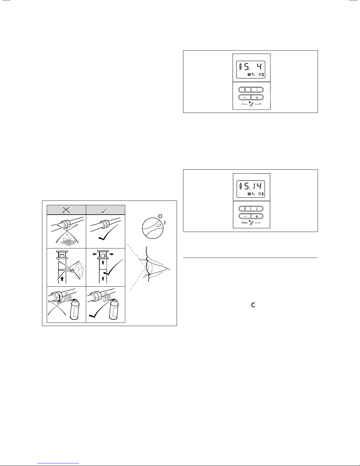
6 Commissioning, Part II: Functional checks
6 Commissioning Part II: Functional
checks
6.1 Functional checks
6.1.1 Method of procedure
After installing and setting the gas, perform a function
check before commissioning the appliance and handing
over to the user.
• Commission the appliance in accordance with the instructions in the relevant operating manual.
• Check the gas supply pipework, the flue system, the
heating system and the hot water pipework for leaks.
• Check that the flue system is properly fitted in accordance with the installation instructions for the flue system.
• Check the ignition and whether the burner is showing
a consistent flame picture.
• Carry out a function check of the heating system (see
Section 6.1.2) and the hot water preparation (see Section 6.1.3).
• Hand over the appliance to the user (see Section 6.2).
Fig. 6.2 Display in heating mode
6.1.3 Hot water operation
• Switch on the appliance.
• Open the hot water tap fully.
• Press "i" to activate the status indicator.
If the hot water operation is operating properly, the display shows "S.14".
Fig. 6.1 Function check
6.1.2 Heating
• Switch on the appliance.
• Make sure that there is a heat demand.
• Press "i" to activate the status indicator.
As soon as there is a heat demand the display runs
through status indications "S. 1" to "S. 3", until the appliance is running properly in normal operation and the
display shows "S. 4".
Fig. 6.3 Display during hot water preparation
6.1.4 Storage tank charging
Note
h
The storage tank charging is delivered de-activated and must be activated during commissioning.
The storage tank charging of the shift load storage tank
is only active if the warm start function is switched on.
This is shown by the symbol
With the storage tank charging function switched on
you can set the following temperatures using the knob
for hot water draw-off temperature:
- Knob setting "b“ 50 °C
- Knob setting "a“ 65 °C
With the storage tank charging function switched off
you can set the following temperatures using the knob
for hot water draw-off temperature:
- Knob setting "c“ 35 °C
- Knob setting "a“ 65 °C
in the display.
Installation and maintenance instructions ecoTEC plus 0020031552_0336
Page 37

Commissioning, Part II: Functional checks 6
1
a
b
c
1
c
1
Fig. 6.4 Setting range for the storage tank temperature
If the storage tank charging function is switched off the
storage tank is not held at temperature. In this case the
unit switches on when water is drawn off and operates
on a through-flow principle.
Danger!
H
Danger of scalding!
The units are fitted with automatic Legionella
protection control:
If the temperature falls below 50 °C in the hot
water storage tank the storage tank is heated
up to 70 °C once every 24 hours. In such a
case there is a danger of scalding when drawing
the water off.
The Legionella protection control can be de-activated in
the diagnosis level "d.74“.
Activating the storage tank charging
• Switch on the appliance.
• Activate the storage tank charging by turning the hot
water temperature control knob fully clockwise.
The symbol "
“ is displayed.
• Turn the hot water temperature control knob to the
temperature you require.
• Press "i" to activate the status indicator.
During the storage tank charging the display shows "S.24“.
a
Fig. 6.5 Display during storage tank charging
De-activating the storage tank charging
• De-activate the storage tank charging by turning the
hot water temperature control knob fully anti-clockwise.
The symbol "
“ disappears.
• Then set the desired hot water temperature. The unit
now operates in the through-flow principle, the storage tank is not held at temperature.
6.1.5 Subsequent flushing through of the heating
system ("hot")
• Allow the appliance to run until both the appliance
and the heating system have reached their operating
temperature.
• Check the heating system for leaks.
• Connect a hose to the drain valve which is located at
the lowest position in the heating system.
• Shut off the appliance, open the drain valve and all
vent valves on the radiators and allow the water to
flow out of the heating system and the combi boiler
quickly and fully.
• Close the drain valve.
• Re-fill the heating system with water as described in
Section 5.4.3.
• Drain water out of the system until a system pressure
of 1.0 bar is reached. (The ideal measured value on the
pressure gauge is 0.5 bar plus an extra amount corresponding to the highest point of the system above the
combi boiler. A height of 10 m corresponds to a pressure increase on the pressure gauge of around 1 bar.
The pressure must not be less than 1 bar on any installation.)
If the system is to be protected by an inhibitor, it
should be added at this stage in accordance with the
manufacturer's instructions.
Further information can be obtained from Sentinel,
Betz Dearborn Ltd., Tel.: 0151 420 9595, or from Fernox, Alpha–Fry technologies, Tel.: 0870 8700362.
• Re-fit the enclosure of the combi boiler (see Section
5.10).
• Fit the base cover to the combi boiler and shift load
storage tank by pushing the front edge of the cover
into the retaining tag on the front lower edge of the
unit framework.
• Carefully push the base cover upwards until the spring
clips on the side of the unit engage. It may be neces-
37Installation and maintenance instructions ecoTEC plus 0020031552_03
Page 38

6 Commissioning, Part II: Functional checks
sary to modify the base cover by removing the easily
removable breakaway sections.
6.2 Handing over the boiler to the owner
Note
h
When you have finished the installation, attach
the sticker supplied (835 593) to the appliance
in the user’s language.
• Set the controller for the maximum radiator temperature to the required temperature.
• Set the controller for the maximum hot water temperature to the required temperature.
• Instruct the operator in the safe and efficient operation of the combi boiler, paying particular attention to
the functions of:
– the ON/OFF switch of the combi boiler,
– the controller for the maximum radiator tempera-
ture,
– the controller for the maximum hot water tempera-
ture (only on combination boilers),
– the pressure gauge.
• Make the operator acquainted with the operation of
any external controllers.
• Explain to the operator the importance of regular
maintenance by a competent heating engineer.
It is strongly recommended that a maintenance contract be taken out to ensure regular maintenance.
Further information can be obtained from Vaillant
Service Solutions (0870 6060 777).
• Enter the operating pressure of the central heating
system, the heat input (in kW) and the temperature
difference between the flow and return in the Benchmark gas boiler commissioning checklist.
If the appliance is not installed and commissioned in
accordance with manufacturer's instructions this can
lead to invalidation of the guarantee (Note: Your legal
rights remain unaffected by this.)
• Leave the operating and installation instructions with
the operator of the appliance.
6.3.2 Registering with us
Registration with us is simple. Just fill in the card for
guarantee registration and return it to Vaillant within
30 days from the date of installation. Your details are
automatically entered in the Vaillant guarantee scheme.
Note
h
A receipt is not issued.
6.3.3 First aid
In the event of a fault on your Vaillant boiler firstly consult your installer since his services must be obtained as
a condition of the guarantee.
If you cannot contact your installer contact Vaillant
Service Solutions on phone number 0870 6060 777.
6.3 Vaillant warranty
6.3.1 Two years warranty
Vaillant is obliged to resolve manufacturing faults which
arise during the first 24 months after installation.
A prerequisite for the effectivity of the guarantee in the
second year is that an annual service is carried out one
year after commissioning by a CORGI registered installer.
The costs for this annual service is not included in the
guarantee. The appliance must be installed by a suitably
competent person in accordance with the Gas Safety
(Installation and Use) Regulations 1998, and the manufacturer‘s instructions. Failure to install and commission
this appliance in accordance with the manufacturer‘s instructions may invalidate the warranty (this does not affect statutory rights).
Installation and maintenance instructions ecoTEC plus 0020031552_0338
Page 39

Inspection and maintenance 7
7 Inspection and maintenance
7.1 First inspection
Regular maintenance and service is recommended to
ensure continued safe and efficient operation of the appliance. The frequency of maintenance and service depends upon the individual installation conditions and
upon the use the appliance is put to. An inspection must
be performed once a year.
Danger!
d
It is a legal requirement that all maintenance
work be performed by competent personnel
(CORGI registered).
Inspection and maintenance work which is not
carried out by a competent person can result in
injury and property damage.
In order to ensure all the functions of the Vaillant appliance over a long period, only genuine Vaillant spare
parts may be used when undertaking maintenance, service and repair work. Any spare parts which might be required are contained in the current Vaillant spare parts
catalogues. Further information can be obtained from
Vaillant Customer Service Centres.
7.1.1 Safety instructions
Important:
Observe the following instructions before starting the
maintenance work:
• Isolate the appliance from the electrical mains by pulling the mains plug out of the socket. (If there is only
an isolator, the fuse must be removed from the
switch).
• Turn OFF the gas supply at the gas isolator valve on
the appliance.
• Take care when removing water-carrying components
that all electrical components are kept away from the
water.
• Always fit new seals and O-rings when replacing components.
• Always carry out a gas tightness test and always carry
out a function check after completion of maintenance
work or after replacing gas-carrying components.
• After all maintenance work and after replacing electrical components check the earth continuity, polarity
and earth resistance using a multi-meter.
Always perform the following steps after performing
any maintenance work:
• Open the stop valves in the heating flow and return
lines and the cold water stop valve.
• If required, fill the unit with cold water up to a pressure of approx. 1.5 bar and bleed the heating system.
• Open the stop valve of the gas supply pipe.
• Turn on the power supply and the main switch.
• Check the appliance for gas and water leaks.
• If necessary, refill and re-bleed the heating system.
Note
h
If it is necessary to keep the main ON/OFF
switch on for certain inspection and maintenance activities this is indicated in the description of the maintenance task.
Note
The appliance is fitted with a combustion analysis test point. A suitable flue gas analyser can
be connected to determine the combustion efficiency of the boiler. This check is required during an annual service (alternative methods are
described if no flue gas analyser is available). A
combustion analyser must be used for the following circumstances:
Replacing the gas valve, converting to or from
natural gas/LPG or if poor combustion is suspected. (see section 9.7).
7.1.2 Maintenance
Carry out a first inspection of the system before starting maintenance or repair work as follows:
• Check the flue system, the pipework and the electrical
connections for signs of damage or wear.
• Check the air supply and ventilation of the installation.
• Check the heating and water system, especially the
condition of the radiator valves, evidence of leaks in
the heating system and dripping hot water taps.
Danger!
e
Electric shock by touching current-conducting
parts can be fatal!
The electrical mains supply terminals in the
electronics box remain live even when the main
switch ON/OFF is switched off.
Protect the electronics box from water splashes.
Before working on the appliance, turn off the
power supply and secure against restart!
39Installation and maintenance instructions ecoTEC plus 0020031552_03
Page 40

7 Inspection and maintenance
7.1.3 Overview of inspection and maintenance tasks
Column 1
No. Step
1 Check flue system and make sure that it is not blocked, not damaged and fixed correctly. x
Measure the gas rate in operation (see Table 5.1 in Section Commissioning, Part l). If the gas
2
rate is less than the minimum value, carry out maintenance work (Column 2).
Check combustion by measuring the CO and CO
Carry out the maintenance if the measured values are outside the tolerances (Column 2). If
flue gas analyser is not available, check the ignition process and the flame picture on the bur-
3
ner through the sight glass; if incomplete combustion is evident carry out maintenance (Column 2)
4 Isolate the unit from the electrical mains, close the gas and the water service valves. x
Inspect the entire primary heat exchanger area for visible signs of corrosion, sooting up or
5
other damage. If damage is detected, carry out maintenance work (Column 2).
Remove compact thermo-module (as described in Section 7.2.1), if maintenance is required as
a result of steps 2, 3 or 5. Clean the primary heat exchanger. Fit seal kit for burner door (ob-
6
serve the fitting instructions included with the seal kit). Re-fit the compact thermo-module
and tighten the nuts.
Check whether the electrical plug connections and other connections are fitted tightly and
7
make adjustments, if necessary.
8 Check expansion vessel of the combi boiler. If required, correct the pressure. x x
values, compare with values in Table 9.2.
2
An inspection
must be perfor-
med once a year.
x
x
x
xx
Column 2
Maintenance
x
9 Check combi boiler in general, check combi boiler for dirt/dust and clean if required. x x
10 Check and clean the condensate trap and discharge pipes. x x
11 Open gas inlet and stop valves, connect unit to the electrical mains and switch on. x x
12 Test the unit and the heating system including the hot water operation. Bleed if required. x x
13 Check the expansion vessel of the shift load storage tank. If required, correct the pressure. x x
Fill the pressure in the combi boiler or in the heating system to approx. 1.0 - 2.0 bar (depen-
14
dent upon the static height of the plant).
Measure the gas rate during operation and check that it is within tolerances (see Table 5.1 in
15
Section Commissioning, Part I).
Check combustion by measuring the CO and CO
measured values must be in tolerance. If there is no combustion analyser is available, check
16
the ignition process and the flame picture on the burner visually through the sight glass;
17 Check the boiler for any leaks and seal if necessary. x x
18 Fill out gas commissioning checklist (Benchmark). x x
Table 7.1 Inspection and maintenance steps
values, compare with values in Table 9.2. The
2
xx
x
x
Installation and maintenance instructions ecoTEC plus 0020031552_0340
Page 41

Inspection and maintenance 7
7.1.4 Function check of the combination boiler
• Carry out a function check of the combi boiler as described earlier.
• Remove the front panel in accordance with the instructions and switch the combi boiler on.
• Check the function of the burner through the sight glass.
• Check that the flames consistently cover the surface
of the burner.
• Take particular notice if the height of the flame is excessive and the production of soot.
7.2 Maintenance of the thermo-compact module
7.2.1 Remonving the thermo-compact module
1
2
• Release the screw and the spring clips on the front
panel located under the front of the unit.
• Remove the front of the of the unit by pulling the bottom edge forwards and lifting slightly.
• Lower the electronic box.
• Unscrew the screw (2) and remove the air inlet pipe (1).
• Separate the gas supply line (3) from the gas valve.
Make sure that the corrugated gas pipe does not twist
by holding the flattened end of the pipe with an openended spanner whilst you release the cap nut.
Caution!
a
Danger of damage to the corrugated gas pipe!
Under no circumstance may the compact thermal module be suspended from the flexible corrugated gas pipe.
4
5
11
10
9
3
Fig. 7.1 Removing the air inlet pipe
The thermo-compact module consists of the burner, the
fan, the gas valve and the gas supply (mixture pipe).
Danger!
d
There is danger of being burned or injured by
the compact thermal module and at all components carrying water. Only carry out work on
these components once they have cooled down.
Proceed as follows to remove it:
• Switch the combi boiler off.
• Isolate the power supply from the combi boiler.
• Remove the bottom cover (if fitted) of the combi boiler by releasing both the spring clips and lowering the
back of the bottom cover downwards.
• Pull the bottom cover slightly towards the back
• Remove the bottom cover from the unit.
• Turn the stop valve off.
• Turn the stop valves of the central heating off.
6
7
Fig. 7.2 Removal of the thermo-compact module
• Pull the ignition cable (5) and the earth wire (6) off
the ignition electrode.
• Unscrew the four nuts (4) from the burner door.
• Pull the two electrical connections (7 and 8) off the
fan and the gas valve.
• Pull the burner, gas valve and fan assembly (9) forwards
off the integral condensation heat-exchanger (10).
Note
h
You can hang the thermo-compact module on
the hook (11) whilst you perform the maintenance work.
• After removing the thermo-compact module clean the
components in accordance with the following description.
8
41Installation and maintenance instructions ecoTEC plus 0020031552_03
Page 42
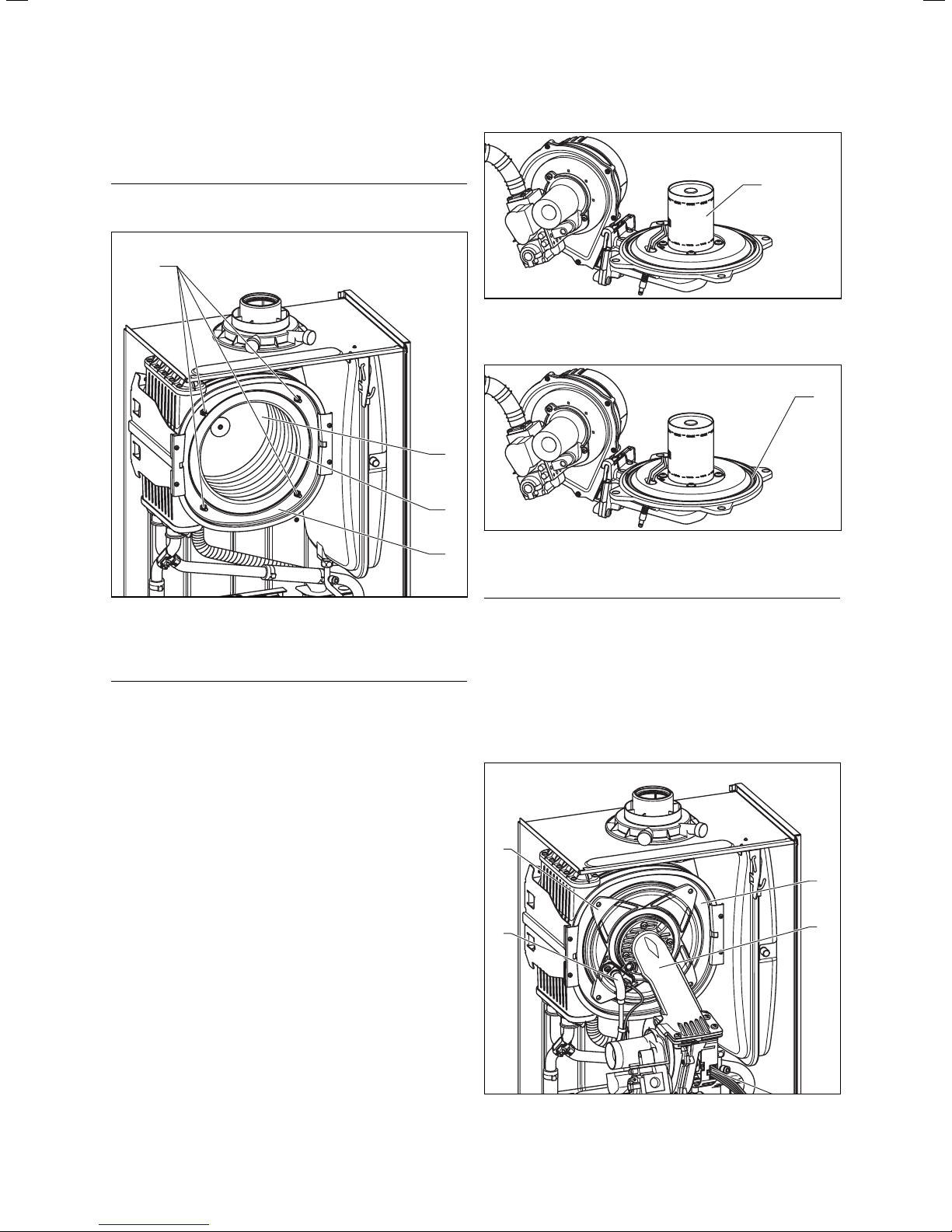
7 Inspection and maintenance 7
7.2.2 Cleaning the integral condensation heatexchanger
Caution!
a
Protect the electronics box from water splashes.
1
1
Fig. 7.4 Checking the burner
7.2.4 Fitting the thermo-compact module
1
2
3
Fig. 7.3 Cleaning the heat-exchanger
• Dismantle the compact thermo module as described
under 7.2.1.
Caution!
a
Danger of damage to the primary heat-exchanger!
Do not attempt to release or tighten the four
screws (1).
After removal of the burner and fan assembly you can
check the primary heat-exchanger (4).
• Remove the loose deposits from the heating coils (3)
with a soft brush and a jet of water. Make sure that
water is kept away from all electrical components. The
water used to clean the primary heat-exchanger runs
away through the condensate siphon. Avoid pointing
the water jet directly at the insulating surface (2) on
the back of the heat exchanger.
If necessary, the heat-exchanger can be cleaned using
ordinary vinegar.
7.2.3 Checking the burner
The burner (1) is maintenance-free and needs no cleaning.
• Check the surface of the burner for damage. If neces-
sary, replace the burner.
• After checking or replacing the burner re-fit the ther-
mo-compact module as described in Section 7.2.4.
Fig. 7.5 Replacing the burner door gasket
4
• Insert a new gasket (1) in the burner door.
Caution!
a
The burner door gasket (1) and the self-locking
nuts on the thermo-compact module must be
replaced every time the module is removed (e.g.
during maintenance, see Table 7.1). If the burner flange insulation on the thermo-compact
module shows any signs of damage or is showing small cracks it must also be replaced.
4
5
6
10
9
Fig. 7.6 Fitting the thermo-compact module
Installation and maintenance instructions ecoTEC plus 0020031552_0342
Page 43

Inspection and maintenance 7
• Insert the compact thermo module (9) in the integral
condensation heat exchanger (10).
• Tighten the four nuts (4) alternately on the left and
right until the burner door closes securely and evenly
over the surface of the heat exchanger.
• Re-connect the ignition cable (5) and the earth
wire (6) to the ignition electrode.
• Connect the cable (8) to the fan motor and the
cable (7) to the gas fitting.
1
2
7.3 Cleaning the condensate siphon
Fig.7.9 Cleaning the condensate siphon
Danger!
d
If the combi boiler is operated with an empty
water condensate trap there is a danger that
poisonous exhaust gases can escape and cause
poisoning. For this reason it is important that
the trap is refilled after each cleaning.
1
3
Fig. 7.7 Connecting the gas supply
• Re-connect the gas supply (3) to the gas valve. Use a
new seal and ensure it is correctly located. Use the
flats of the spanner on the flexible gas pipe to hold
the gas fittings in position.
11
Fig. 7.8 Checking the gas supply for leaks
• Turn on the gas supply and check for leaks. Pay par-
ticular attention to fittings (3) and (11).
• Re-connect the air inlet pipe (1) and make sure that
the blue seal is correctly located in the air inlet pipe.
• Remove the lower section (1) of the water condensate
siphon by turning the bayonet connection in a counterclockwise direction.
• Clean the siphon part by flushing it out with water.
• Fill the lower section with water until about 10 mm
below the upper edge.
• Re-fit the lower section to the condensate siphon.
7.4 Cleaning strainer in cold water supply
There is a strainer in the cold water supply to the combi
boiler which must be cleaned during maintenance.
1
2
3
Fig.7.10 Cleaning strainer in cold water supply
43Installation and maintenance instructions ecoTEC plus 0020031552_03
Page 44
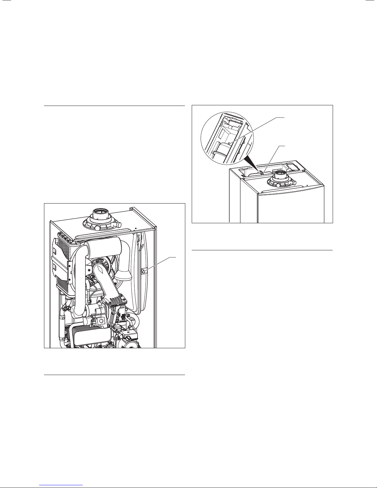
7 Inspection and maintenance
• Isolate the unit from the electric mains in the appartment as described in 8.2.
• Close the cold water stop valve on the inlet combination (see Fig. 7.10) and drain the unit from the hot
water side.
• Release the fitting (1) of the cold water inlet.
• Release the fitting (3) on the connector (2).
Note
h
The fitting (3) is located above the elbow (2)
and is not shown in Fig. 7.10.
• Remove the connector (2) from the chassis.
• Flush the connector out under flowing water in the
opposite direction to normal flow.
• Re-fit the connector with the cleaned strainer.
• Fit the pipe elbows of the shift load storage tank and
the cold water feed back in position.
• Always use new seals.
7.5 Checking filling pressure of the expansion
vessel of the combination boiler
If the pressure is less than this, the vessel must be
pumped up again using an air pump.
• Refit the valve cover.
• Re-pressurise the combi boiler and the heating system.
7.6 Checking filling pressure of the expansion
vessel of the shift load storage tank
2
1
Fig. 7.12 Checking filling pressure of the expansion vessel of
the shift load storage tank
1
Fig. 7.11 Checking filling pressure of the expansion vessel of
the combination boiler
Note
h
This check need not be performed every year –
a check every three years is sufficient.
• Turn the stop valvess of the central heating off.
• Release the pressure from the appliance.
• Remove the valve cover from the expansion vessel.
• Check that the internal pressure in the expansion vessel is between 0.75 and 0.9 bar.
Note
h
This check need not be performed every year –
a check every three years is sufficient.
• Close the stop valves of the hot water system.
• Release the pressure from the appliance.
• Release the screw on the top cover of the shift load
storage tank and remove the cover.
The expansion vessel (1) is freely accessible
• Unscrew the seal cap (2) from the expansion vessel.
• Check that the internal pressure of the expansion vessel is approx. 4 bar.
If the pressure is less than this, the vessel must be
pumped up again using an air pump.
• Screw the seal cap (2) back onto the expansion vessel.
• Re-fit the cover.
• Re-pressurise the combi boiler and the hot water system.
7.7 Re-commissioning the combination boiler
• Carry out the electrical safety tests.
• Switch on the electrical supply.
• Turn the stop valves of the central heating on.
• Carry out a function check of the combi boiler as described earlier.
• Check the gas rate as described earlier.
• Check for water leaks.
• Re-fit the front case. Make sure that the seal is good.
Installation and maintenance instructions ecoTEC plus 0020031552_0344
Page 45

7.8 Test mode
Always perform the following steps after performing
any maintenance work:
• Commission the appliance in accordance with the instructions in the relevant operating manual.
• Check the appliance for gas and water leaks.
• Check the entire air/flue gas system for leaks and securely fixed.
• Check ignition and even flame appearance of the
burner.
• Check whether the heating system and the hot water
preparation is functioning.
• Complete the Benchmark gas boiler commissioning
checklist in the rear section of these instructions.
Inspection and maintenance 7
Fig. 7.13 Function check
45Installation and maintenance instructions ecoTEC plus 0020031552_03
Page 46

8 Troubleshooting
8 Troubleshooting
8.1 Logical fault finding procedure
Carry out the following checks before the actual troubleshooting:
• Carry out the tests to check electrical safety (see Section "Preparatory Checks on the Electrical System").
• Check that the external power supply for the combi
boiler is switched on and that there is a supply voltage
of 230 V AC between the connections "L" and "N".
• Check that the gas supply to the combi boiler is
switched on.
• Check that the combi boiler has been properly purged
and that there is a supply pressure of 20 mbar the
inlet to the boiler. (See Section "Gas Supply".)
• Check that the heating system is filled with water and
that there is a pressure of between 1.0 and 1.5 mbar.
Otherwise top up the system and bleed. (See Section
"Filling the Heating System".)
• Check that the stop valves in the flow and return lines
of the combi boiler are open.
• Check that the mains switch is set to "ON".
• Set the temperature of the central heating to "Maximum".
• Set the temperature of the hot water preparation to
"Maximum".
• Check that all external controllers are switched on
and are demanding heat (if no external controllers are
fitted, the connections 3 and 4 on the combi boiler
terminal must be connected together).
• Check that the burner anti-cycling time mode on the
combi boiler is not active.
8.1.1 Status codes
The status codes which you can see in the display provide information concerning the current operating status of the unit.
Proceed as follows to display the status codes:
Fig. 8.1 Display of status codes
• Press the "i" button.
The display shows the status code e.g. S.04 for the
"Burner mode - heating".
The status code display can be de-activated as follows:
• Press the "i" button. or
• Do not press any button for about 4 minutes.
The current heating flow temperature appears in the
display again.
Display Meaning
Heating mode:
S.0 No heat demand
S.1 Fan running
S.2 Pump running
S.3 Ignition
S.4 Burner ignited
S.5 Fan and pump running
S.6 Fan over run
S.7 Pump overrun time
S.8 Anti-cycling mode
Hot water mode (ecoTEC plus 800 models only):
S.10 Hot water request
S.11 Fan running
S.13 Ignition
S.14 Burner ignited
S.15 Fan and pump running
S.16 Fan over-run
S.17 Pump over-run
Warm start mode/hot water storage tank charging:
S.20 Pump running
S.21 Fan running
S.23 Ignition
S.24 Burner ignited
S.25 Fan and water pump running
S.26 Fan over-run
S.27 Pump over-run time
S.28 Anti-cycling mode
All boilers:
S.30
S.34 Antifrost mode active
S.36
S.42
S.53
S.54
S.96
S.97
S.98
Table 8.1 Status codes (continuation see next page)
No heat demand from external controllers (terminal
3-4 open)
Thermostat knob of central heating switched off or
S.31
no heat demand from an eBUS controller
Heat exchanger antifreeze active, as fan speed varia-
S.32
tion is too high. Appliance is within the waiting time
of the operation block function
No heat demand from low voltage regulators (terminal 7-8-9)
S.41 Water pressure >2.9 bar
Feedback from accessories module or defective condensate pump blocks the burner operation
Appliance is within the waiting period of the modulation block/operation block function due to water
shortage (flow-return spread too large)
Appliance is within the waiting period of the operation block function due to water shortage (temperature gradient)
Return flow sensor test, heat demands (hot water or
heating) are blocked
Water pressure sensor test, heat demands (hot water
or heating) are blocked
Flow/return flow sensor test, heat demands (hot
water or heating) are blocked
Installation and maintenance instructions ecoTEC plus 0020031552_0346
Page 47

Troubleshooting 8
8.1.2 Diagnostic codes
In the diagnostic mode, you can change certain parameters or display more information.
The diagnostic information is divided into two diagnostic
levels. Access to the second diagnostic level can only be
permitted after entering a password.
• Use the buttons "+“ or "–“ to move to the desired di-
agnostic number of the first diagnostic level (see the
Table 8.2).
• Press the "i" button.
The associated diagnostic information is shown in the
display.
• If necessary you can change the value with the but-
Caution!
a
Danger of incorrect operation and wrong unit
parametrisation!
Access to the second diagnostic level must be
used exclusively by a heating engineer.
tons "+“ or "–“ (display flashing).
• Save the new value by holding down the "i“ button for
approx. 5 seconds until the display no longer flashes.
You can end the diagnostic mode as follows:
• Press the "i“ and "+“ buttons simultaneously. or
• Do not press any button for about 4 minutes.
First diagnostic level
• Press the "i“ and "+“ buttons simultaneously.
The display shows "d.00“.
Display
Table 8.2 Diagnostic codes of the first diagnosis level
Meaning Displayed value/settable value
d.0 Heating partial load Adjustable heating partial load in kW (factory setting: max. output)
d.1 Water pump over run time for heating mode 2 - 60 minutes (factory setting: 5 minutes)
d.2 Max. anti cycle time heating at 20°C flow temperature 2 - 60 minutes (factory setting: 20 minutes)
d.3 Measured value of the domestic hot water temperature in °C
d.4 Measured value for the warmstart sensor in °C
d.5 Flow temperature target value or return temperature tar-
get value, if return flow regulation selected
d.6 Hot water target temperature in °C, 35 to 65 °C
d.7 Warm start target temperature in °C, 40 to 65 °C
d.8 Heat demand of external controllers (terminal 3-4) 1=closed (heating requirement); 0=opened (no heating requirement)
d.9 Flow target temperature from external analogue regulator
to terminal 7-8-9/eBus
d.10 Status internal heating pump 1, 2 = on, 0 = off
d.11 Status external heating pump (via accessory module) 1 to 100 = on, 0 = off
d.12 Cylinder charging pump (via accessories module) 1 to 100 = on, 0 = off
d.13 External hot water circulation pump (via accessory module) 1 to 100 = on, 0 = off
d.22 Hot water demand 1 = on, 0 = off
d.23 Summer /winter function 1 = Winter, 0 = Summer
d.25 Hot water activation via eBUS controller 1 = yes, 0 = no
d.30 Control signal for both gas valves 1 = on, 0 = off
d.33 Fan speed target value in upm/10
d.34 Fan speed actual value in upm/10
d.35 Internal diverter valve position 0 = heating; 100 = hot water; 40 = mid-position
d.36 Hot water flow sensor in l/min
d.40 Flow temperature actual value in °C
d.41 Return flow temperature actual value in °C
d.44 digitalised ionisation voltage Display range 0 to 102, >80 no flame, <40 good flame display
d.47 External temperature (only on weather-compensated
Vaillant controllers)
d.67 Remaining burner anti-cycling time in minutes
d.76 Unit variants (device specific number) 00 to 99
d.90 Status of the digital controller 1 = identified, 0 = unidentified (eBUS Address <=10)
d.91 DCF status with connected external probe with DCF77 re-
ceiver (not available in the UK)
d.92 Module recognition shift load storage tank Setting range:
d.97 Activation of the second diagnostic level Password: 17
The current heating flow temperature appears in the
display again.
in °C, max. of the value set in d.71
limited by an eBUS controller, if fitted)
in °C, minimum from ext. eBus target value and target value
terminal 7
actual value in °C
0 = no reception, 1 = reception, 2 = synchronised, 3 = valid
0 = not recognised
1 = no communication via PE-BUS; Module recognised earlier
2 = Communication OK
Setting = 0: Unregister shift load storage tank from combi boiler
(if shift load storage tank is to be de-installed, set d.92 = 0)
47Installation and maintenance instructions ecoTEC plus 0020031552_03
Page 48

8 Troubleshooting
Second diagnostic level
• As described above in the first diagnostic level, scroll
Scroll and change values and exit diagnosis mode as described in the first diagnosis level.
through to the diagnosis number d.97.
• Change the displayed value to 17 (Password) and push
the button "i".
Note
h
If you push the buttons "i" and "+" again within 4 minutes after leaving the second diagnosis
You are now in the second diagnostic level where all information from the first diagnostic level (see Table 8.2)
and the second diagnostic level (see Table 8.3) is dis-
level you will go directly to the second diagnosis level without having to enter the password
again.
played.
Display Meaning Displayed value/settable value
d.17 Heating flow/return regulation changeover 0 = flow, 1 = return (factory setting: 0)
d.18 Pump mode (return flow) 0 = overrun, 1 = continuous, 2 = winter (Factory setting: 0)
d.19 Operating modes of the two-speed heating pump 0 = Pre-ignition speed 1, Hot water or heating speed 2, overrun
d.20 Maximum set value for external cylinder target tempera-
ture (system boilers only)
d.27 Switching relay 1 on the accessories module 1 = Circulation pump (factory setting)
speed 1
1 = Pre-ignition speed 1, hot water speed 2, heating speed 1, overr-
run speed 1
2 = Like 1 but speed in heating mode dependant on heating part
load d.0 (if d.0 is below 60 % of full load, then pump speed 1,
otherwise speed 2); Factory setting 2)
3 = Always speed 2
Setting range: 50 °C to 70 °C (Factory setting 65 °C)
2 = Ext. Pump
3 = External cylinder charging pump
4 = Flue gas flap/extractor hood
5 = External gas valve
6 = External error message
d.28 Switching relay 2 on the accessories module 1 = Circulation pump
d.50 Offset for minimum fan speed in upm/10, adjustment range: 0 to 300
d.51 Offset for maximum fan speed in upm/10, adjustment range: -99 to 0
d.58 Activation solar pre-heat function Setting range: 0 to 3
d.60 Number of safety temperature limiting switch-offs Quantity
d.61 Number of unsuccessful ignitions Number of successful ignitions in the last attempt
d.64 Average ignition duration in seconds
d.65 maximum ignition duration in seconds
d.68 Successful ignitions at the first attempt Quantity
d.69 Successful ignitions at the second attempt Quantity
d.70 Setting the diverter valve position 0 = Normal mode (factory setting)
d.71 Maximum flow temperature knob setting Adjustment range in °C 40 to 85 (Factory setting: 75)
Table 8.3 Diagnostic codes in the second level
2 = Ext. pump (factory setting)
3 = External cylinder charging pump
4 = Flue gas flap/extractor hood
5 = External gas valve
6 = External error message
0 = solar post-heating deactivated (factory setting)
3 = Activation hot water target value min = 60 °C for solar pre-
heat
1 = mid-position
2 = Permanent heating position
Installation and maintenance instructions ecoTEC plus 0020031552_0348
Page 49

Troubleshooting 8
Display Meaning Displayed value/settable value
d.72 Pump overrun time after warm start or shift load storage
tank charging
d.73 Offset for warm start target temperature Setting range: -15 K to +5 K (Factory setting: 0K)
d.74 Legionella protection shift load storage tank Setting range:
d.75 Maximum charging duration for an external cylinder wit-
hout its own control (system boilers only)
d.77 Part load of the external cylinder (limit for charging capa-
city of the external cylinder, system boilers only)
Setting range in seconds: 0, 10, 20 to 600
Factory setting: 80
0 = deactivated
1 = activated (Factory setting)
Adjustment range in min: 20, 21, 22 to 90 (Factory setting: 45)
Adjustment range in kW: appliance specific
Factory setting: max. output
d.78 Limit for charging temperature of the external cylinder
(target flow temperature in storage tank mode, system
boilers only)
d.80 Operating hours heating in h
d.81 Operating hours hot water generation in h
d.82 Operating cycles in heating mode number/100
d.83 Cycles in hot water operation number/1001) (3 equals 300)
d.84 Maintenance indicator: Number of hours until the next
maintenance
d.88 switching on threshold for recognizing water tapping
(only VCW)
d.92 Module recognition shift load storage tank Setting range:
d.93 DSN appliance variant setting Setting range: 0 to 99
d.96 Factory reset 1 = Resetting adjustable parameters to factory setting
1)
In the diagnostic codes 80 to 83 5 digit figure values are stored. When selecting e.g. d.80 only the first two digits of the figure value
are displayed (e.g.10). By pressing the „i“ key, the display switches over to the last three figures (e.g. 947). The operating hours counter of the heating in this case would be 10947 h. Pressing the „i“ again causes the display to switch back to the diagnosis point that
was called up.
Table 8.3 Diagnosis codes of the second diagnosis level
Adjustment range in °C 55 to 85 (Factory setting: 80)
1)
(3 equals 300)
Setting range: 0 to 3000h and „-“ for deactivated
Factory setting: „-“ (300 corresponds to 3000h)
0 = 1,5 l/min and no delay,
1 = 3,7 l/min and 2s delay
0 = not recognised
1 = no communication via PE-BUS; Module recognised earlier
2 = Communication OK
Setting = 0: Unregister shift load storage tank from combi boiler
(if shift load storage tank is to be de-installed, set d.92 = 0)
8.1.3 Error codes
Fault codes take priority over all other display functions
in the event of a system fault occurring.
If many errors occur simultaneously, the relevant error
codes are displayed alternately for approx. 2 seconds
each.
8.1.4 Fault memory
The fault memory of the unit stores the information
concerning the last ten errors.
• Press the "i“ and „-“ buttons simultaneously.
• Scroll backwards with button "+“ through the list of
stored errors.
You can exit the error memory display as follows:
• Push the button "i“under the display, or
• Do not press any button for about 4 minutes. The display then switches back to the display of current flow
temperature.
49Installation and maintenance instructions ecoTEC plus 0020031552_03
Page 50

8 Troubleshooting
Code Meaning Cause
F.0 Flow NTC open circuit
F.01 Return NTC open circuit
Shift load storage tank charging (NTC) open circuit,
F.02
only in combination with F.91
Shift load storage tank temperature (NTC) open circuit,
F.03
only in combination with F.91
F.10 Flow NTC short circuit NTC faulty, NTC plug short-circuited to casing
F.11 Return NTC short circuit NTC faulty, NTC plug short-circuited to casing
Short circuit in storage tank charging sensor (NTC)
F.12
only in combination with F.91
Short circuit storage tank temperature sensor (NTC)
F.13
only in combination with F.91
F.20 Safety temperature limiter by NTC activated
F.22 Dry fire
Water shortage, temperature spread between flow and
F.23
return NTC too large
F.24 Water shortage, temperature rise too quick
F.25 Compact thermal module wiring harness open circuit Wiring harness thermo-compact module faulty
F.27 Incorrect sensing of flame Flame monitor faulty
F.28 Unit will not start: Attempts to ignite during start failed
Flame goes off during operation and subsequent ignition
F.29
attempts failed
F.32 Speed deviation Fan
F.49 eBUS undervoltage
F.61 Gas valve control faulty
F.62 Switch-off delay of the gas valve faulty gas valve leaking, electronics defective
F.63 EEPROM error Defective electronics
F.64 Electronics/NTC fault
F.65 Electronics temperature too high Electronics too hot due to external effect, electronics defective
F.67 Flame monitor input signal is outside the limits (0 or 5 V) electronics defective
No valid appliance variant for display and/or electronics
F.70
(DSN number invalid)
F.71 Flow NTC reports constant value Flow NTC is defective
F.72 Flow and/or return NTC fault Feed and/or return NTC is faulty (tolerance too great)
Signal water pressure sensor in the wrong range
F.73
(too low)
Signal water pressure sensor in the wrong range
F.74
(too high)
No sudden change in pressure was detected on turning
F.75
on the pump
Overheating protection on primary heat-exchanger
F.76
activated
Condensate pump or return signal from accessory
F.77
module blocks heating
F.78 Incorrect configuration of accessories Control Center VR 65 connected to combination boiler
Interruption or short-circuit of SWT inlet sensor only in
F.80
conjunction with F.91
Table 8.4 Error codes
NTC faulty, NTC cable faulty, faulty plug connection on NTC,
faulty plug connection on the electronics
NTC faulty, NTC cable faulty, faulty plug connection on NTC,
faulty plug connection on the electronics
NTC faulty, NTC cable faulty, faulty plug connection on NTC,
faulty plug connection on the electronics
NTC faulty, NTC cable faulty, faulty plug connection on NTC,
faulty plug connection on the electronics
Sensor plug has mass short to the casing, short-circuit in wiring
loom, sensor faulty
Sensor plug has mass short to the casing, short-circuit in wiring
loom, sensor faulty
Flow probe not connected thermally correct or defective, appliance does not shut down
Too little water in the appliance, water pressure sensor defective, cable to pump or water pressure sensor defective, pump
seized or defective, pump output too low
Pump seized or defective, pump output too low, flow and return
sensor swapped over
Pump seized, low output from the pump, air in appliance, system
pressure too low
Faults in the gas supply such as:
- Gas meter or gas pressure regulator
- Air in gas
- Gas flow pressure too low
Faults in the gas valve, wrong gas setting, igniter (ignition transformer, ignition cable, ignition plug) defective, ionisation current
stopped (cable, electrode), faulty earthing in appliance, electronics defective
Gas supply temporarily interrupted, defective earthing of the unit
Fans seized, plug not inserted correctly on fan, hall sensor de-
fective, fault in cable harness, electronics defective
Short-circuit on eBUS input, eBUS overload or two power sup-
plies with different polarities on the eBUS
Short circuit/earth(ground) leak in cable harness to gas valve,
gas valve assembly defective (earth/ground leak from solenoid),
electronics fault.
Short-circuit in flow or return NTC or electronics defective/ air
in gas
Spare parts error: Display and electronics changed at the same
time appliance variant not re-set
Line to water pressure sensor is interrupted or has a short-circuit to 0 V or water pressure sensor faulty
Harness to water pressure sensor has a short-circuit at
5 V / 24 V or internal fault in water pressure sensor
Water pressure sensor and/or pump faulty (pump seized - check
system water for contamination)
Air in heating system, automatic air vent system faulty
Too little water in the unit; check adjustable bypass;
Connect expansion vessel in return;
Cable or cable connection of fuse in the primary heat exchanger
defective, replace primary heat exchanger
Condensate pump faulty or return signal from the exhaust gas
flap has activated
NTC defective, NTC cable defective, defective plug connection at
NTC, defective plug connection at APC electronics
Plug at sensor has short-circuited to housing, short-circuit in
cable harness, sensor defective
Installation and maintenance instructions ecoTEC plus 0020031552_0350
Page 51

Code Meaning Cause
F.81 APC loadpump fault connected to F.91
Communication with shift load storage tank module
F.90
interrupted
F.91 Sensor error on shift load storage tank module (NTC)
con No communication with the printed circuit board
Table 8.4 Error codes
Troubleshooting 8
Storage tank is not fully charged after a specific period of time.
-Check storage tank charge sensor and storage tank sensor
-Air in the APC pump
-Check pump wiring harness
-Secondary heat exchanger blocked
-Priority changeover valve defective
-Pump defective
Check wiring harness from combi boiler to shift load storage
tank (PE Bus). If combi boiler is to be operated without shift load
storage tank, set d.92 = 0
NTC faulty, NTC cable faulty, faulty plug connection on NTC,
faulty plug connection on the electronics
Communication fault between the display and the printed circuit
board in the electronics box
8.2 Test programmes
Special functions can be triggered in the appliance by
activating various test programs.
These programmes are listed in detail in Table 8.5.
• The test programmes P.0 to P.6 will be started when "
Power ON“ is turned on and the "+“ button is pressed
for 5 seconds simultaneously.
The display shows "P.0“.
• Press the "+" key to start counting the test pro-
gramme number upwards.
• Press the "i“ to operate the appliance now and to
start the test programme.
• To de-activate the setting mode, simultaneously push
the buttons "i“ and "+“. You can also end the test
programmes by not pushing any button for a 15 minute
period.
Display Meaning
Bleeding test program The heating circuit and
the hot water circuit (only on combination boilers)
P.0
are bled via the automatic air vent (the cap of the
automatic air vent must be released two turns).
Test programme where the appliance is operated
P.1
in full load after successful ignition.
Test program where the appliance is operated
P.2
with minimum gas volume (ignition gas volume)
after successful ignition
8.3 Resetting the parameters to factory settings
Besides the option to reset individual parameters
manually to the factory settings specified in Tables 9.2
and 9.3, you can also reset all parameters simultaneously.
• In the second diagnostic level, under the diagnostic
point "d.96" change the value to 1 (see Section 8.1.2).
The parameters of all adjustable diagnosis points now
correspond to the factory settings.
P.3 not available
P.4 not available
Test programme for checking the safety temperature limitation: The unit is heated by avoidance
P.5
of the regular switch-off by the feed regulator until
a temperature of 97 °C is reached.
Filling programme: The diverter valve moves to
P.6
the centre position.
Table 8.5 Test programmes
51Installation and maintenance instructions ecoTEC plus 0020031552_03
Page 52

9 Replacing components
9 Replacing components
The tasks listed below may only be undertaken by a
qualified competent heating engineer.
• Only use genuine spare parts for repairs.
• Check that the parts are correctly fitted and that the
original location and alignment is maintained.
9.1 Safety instructions
Danger!
d
Every time components are replaced observe
the following safety instructions for your own
safety and to prevent damage to the unit!
Take the appliance out of operation.
Danger!
e
Danger of death by electric shock!
Before starting any maintenance work:
Isolate the unit from the electrical mains by
pulling the plug out of the plug socket (if only
an isolator switch is available, remove the fuse
from the switch.)
• Close the stop valves in the gas supply and in the
heating flow and return pipes.
• Close the cold water inlet stop valve (only on combi
boilers).
• Drain the unit if you wish to replace water-conducting
components in the unit.
• Make sure that no water drips on live electrical components (e.g. electronic box etc.)!
• Use only new gaskets and O-rings!
• Check the system for gas leaks after completion of
the work. Carry out a function test (see Section 7.8).
• After all maintenance work and after replacing electrical components check the earthing, polarity and earth
resistance using a multi-meter.
• Dismantle the compact thermo module as described
under 7.2.1.
• Release the 4 screws (1) on burner, and remove the
burner.
• Mount the new burner with a new gasket. The notch in
the burner must be aligned with the sight glass of the
burner.
• Fit the compact thermo module as described under
7.2.4.
• Fit a new burner door seal kit.
• After completion of the work check the system for gas
leaks and carry out a function test (see Section 7.8).
Note
h
A new burner door seal kit must be fitted every
time the burner door is removed.
9.3 Replacing the fan or gas valve
Danger!
d
Before replacing components ensure that the
safety instructions from Section 9.1 are observed.
• Switch the combi boiler off.
• Isolate the electrical supply from the combi boiler.
• Remove the air intake pipe (Fig. 7.1, Pos. 2).
• Loosen the gas supply pipe on the gas valve (Fig. 7.2,
Pos. 3).
1
9.2 Replacing the burner
Danger!
d
Before replacing components ensure that the
safety instructions from Section 9.1 are observed.
1
Fig. 9.1 Replacing the burner
2
4
Fig. 9.2 Removing the fan with gas fitting
• Pull the plug (4) out of the gas valve.
• Pull the plug (3) out of the fan.
• Unscrew the three screws (2) out of the thermo-compact module (1).
• Remove the complete component group "gas valve/
fan".
Installation and maintenance instructions ecoTEC plus 0020031552_0352
3
Page 53

Replacing components 9
5
Fig. 9.3 Gas valve/fan screwed joint
• Release both fixing screws (5) on the gas valve and
remove the fan from the gas valve.
• Replace the faulty component.
Caution!
a
Danger of damage to the equipment!
Fit the gas valve and fan in the same position
as before.
• Screw the fan onto the gas valve.
Use new seals.
• Re-install the complete "gas valve/fan" unit in reverse
sequence.
• After completion of the work check the system for gas
leaks and carry out a function test (see Section 7.8).
9.4 Replacing the expansion vessel
Danger!
d
Before replacing components ensure that the
safety instructions from Section 9.1 are observed.
• Disconnect the appliance from the mains as described
in Chapter 9.1, and close the gas isolator valve in the
gas supply pipe.
• Close the stop valves in the flow and return pipes and
drain the water out of the combi boiler.
• Unscrew the nuts (4) from the water pipe on the underside of the expansion vessel.
• Unscrew the two screws (1) in the retaining plate (2)
and remove the retaining plate.
• Pull out the expansion tank (3) forwards.
• Guide the new expansion tank back into the appliance.
• Re-connect the new expansion tank using a new gasket.
• Re-fit the retaining plate.
• Check the pressure of the expansion tank (minimum
pressure 0.75 bar).
If required, match the pressure to the static head of
the heating system.
• Fill and vent the combi boiler.
• After completion of the work check the system for gas
leaks and carry out a function test (see Section 7.8).
1
2
3
4
Fig. 9.4 Replacing the expansion vessel
9.5 Replacing the primary heat exchanger
Danger!
d
Before replacing components ensure that the
safety instructions from Section 9.1 are observed.
• Disconnect the appliance from the mains as described
in Chapter 9.1, and close the gas isolator valve in the
gas supply pipe.
• Close the stop valves in the flow and return pipes and
drain the water out of the combi boiler.
• Remove the compact thermo module as described
under 7.2.1.
• Remove the expansion tank as described under 9.4.
• Pull off the condensate pipe which runs from the primary heat-exchanger to the siphon.
• Remove the clamps (1) and (2) and pull off the flow
and return hoses from the primary heat-exchanger.
• Unscrew the four screws (3) on the holder of the primary heat-exchanger.
53Installation and maintenance instructions ecoTEC plus 0020031552_03
Page 54

9 Replacing components
3
1
2
4
Fig. 9.5 Replacing the primary heat exchanger
Note
h
A new burner door seal kit must be fitted every
time the burner door is removed.
Caution!
a
Danger of damage to the primary heat-exchanger!
Do not release or tighten the four screws
(Fig. 9.5, Item 4).
Caution!
Insert the „O“-rings for the flow and return
hoses on the primary heat-exchanger using a
suitable lubricant.
Push the flow and return connections up to the
stop in the primary heat-exchanger and make
sure that the seating of the clamps on the flow
and return hoses are correct (see Fig. 9.5).
• Filling and vent the combi boiler as required.
• After completion of the work check the system for gas
leaks and carry out a function test (see Section 7.8).
9.6 Replacing the expansion vessel of the shift
load storage tank
1
2
3
Fig. 9.6 Holder for the primary heat-exchanger
• Pull the plug connection (2) of the thermal fuse off
the primary heat-exchanger.
• Unscrew the three screws (3) on the holder of the pri-
mary heat-exchanger.
• Turn the holder to the side around the rivet (1), pull
the primary heat exchanger downwards to the right
and remove it from the appliance.
• Mount the new primary heat exchanger
• Fit a new burner door seal kit.
• Fit the burner module.
• Continue to replace in the reverse order.
2
1
Fig. 9.7 Replacing the expansion vessel of the shift load stor-
age tank
Danger!
d
Before replacing components ensure that the
safety instructions from Section 9.1 are observed.
• Disconnect the appliance from the mains as described
in Section 9.1, and close the gas isolator valve in the
gas supply pipe.
• Close the cold water inlet stop valve.
• Open a hot water tap in order to release the pressure
on the water circuit. Then close the tap again.
Installation and maintenance instructions ecoTEC plus 0020031552_0354
Page 55

Replacing components 9
• Remove the screw on the cover of the shift load storage tank.
• Remove the cover.
• The expansion vessel (1) is freely accessible
• Release the nuts (2) on the expansion tank.
• Pull the expansion tank (1) off the pipe fitting and remove it from the EPS trough.
• Insert the new expansion tank in the EPS trough.
• Re-connect the new expansion tank. Use a new gasket:
• Check the pressure of the expansion tank (minimum
pressure 4 bar).
• Filling and vent the combi boiler and the shift load
storage tank.
• After completion of the work check the system for gas
leaks and carry out a function test (see Section 7.8).
9.7 Replacing the storage tank pump of the shift
load storage tank
1
6
5
4
• Remove the discharge pipe (1) of the heating pressure
relief.
• Lower the electronics box as described in Section 4.19.2.
• Unclip the back cover of the electronics box and swing
the cover upwards to reveal the connections.
• Pull the plug X12 off the electronic printed circuit
board.
• Pull the free end of the line carefully through the
entry grommets on the combi boiler and on the shift
load storage tank.
• Release the sensor wire of the pump from the wiring
harness by pulling the plug off the wiring harness.
• Unscrew the sheet metal bracket (6) from the chassis.
• Release the fitting (2) on the connector pipe (3).
• Release the spring clamp (5) on the storage tank
charging pump casing (4). Support the storage tank
charging pump with your other hand to prevent it
from falling out of the chassis.
• Pull the storage tank charging pump out of the chassis downwards.
• Fit the pipe bracket to the new storage tank charging
pump using new gaskets.
• Fit the new storage tank charging pump in reverse
order and use new gaskets.
• Connect the electrical wires of the pump in reverse
sequence. Check for correct routing of the lines.
• Re-fit the discharge pipe (1) and use new gaskets.
• Filling and vent the combi boiler and the shift load
storage tank.
• After completion of the work check the system for gas
leaks and carry out a function test (see Section 7.8).
2
3
Fig. 9.8 Replacing storage tank pump
Danger!
d
Before replacing components ensure that the
safety instructions from Section 9.1 are observed.
• Isolate the unit from the mains as described in Section 9.1.
• Close the gas isolator valve in the gas supply pipe.
• Close the stop valves in the hot water system and
drain the water out of the combi boiler and the shift
load storage tank.
9.8 Replacing the aqua sensor
1
5
4
3
Fig. 9.9 Replacing the aqua sensor
2
55Installation and maintenance instructions ecoTEC plus 0020031552_03
Page 56

9 Replacing components
Danger!
d
Before replacing components ensure that the
safety instructions from Section 9.1 are observed.
• Isolate the unit from the mains as described in Section 9.1.
• Close the gas isolator valve in the gas supply pipe.
• Close the stop valves in the hot water system and
drain the water out of the combi boiler and the shift
load storage tank.
• Remove the discharge pipe (1) of the heating pressure
relief.
• Separate the electrical wire of the aqua sensor from
the wiring harness by pulling off the plug from the
wiring harness.
• Release the fitting (2) and (3) on the elbows (4)
and (5).
• Turn the Aqua-Sensor slightly to the side and pull the
Aqua-Sensor downwards out of the chassis.
• Remove the pipe elbow from the Aqua-Sensor.
• Fit the pipe elbow onto the new Aqua-Sensor and use
new gaskets.
• Mount the new Aqua-Sensor in reverse order and replace the seals.
• Connect the line plug of the Aqua-Sensors with the
wiring harness.
• Re-fit the discharge pipe (1) and use new gaskets.
• Filling and vent the combi boiler and the shift load
storage tank.
• After completion of the work check the system for
water leaks and carry out a function test (see Section 7.8).
• Isolate the unit from the mains as described in Section 9.1.
• Close the gas isolator valve in the gas supply pipe.
• Comply with the assembly and installation manuals
provided with the spare parts.
• Remove the screw on the top cover of the shift load
storage tank and remove the cover.
• Pull the electronics (1) out of the location slot.
• Pull off the plug connector from the wiring harness.
• Fit the new electronics in reverse order.
• Start up the appliance.
Check the correct setting of the unit variants (DSN) as
follows:
• Enter the 2nd diagnostic level of the combi boiler .
• Set the equipment-specific DSN value (parameter
"d.93“) in accordance with Table 10.1.
Appliance type DSN
ecoTEC plus 937 8
Table 9.1 DSN Setting Values
• Exit the diagnostic mode.
The combi boiler ecoTEC plus 937 is ready for operation.
9.10 Replacing the electronics and the display on
the combination boiler
Danger!
d
Before replacing components ensure that the
safety instructions from Section 9.1 are observed.
9.9 Replacing the electronics on the shift load
storage tank
1
Fig. 9.10 Replacing electronics
Danger!
d
Before replacing components ensure that the
safety instructions from Section 9.1 are observed.
• Comply with the assembly and installation manuals
provided with the spare parts.
Replacing the display or the electronics
If you are only replacing one of the two components the
parameter settings take place automatically. When
switching the unit on the new component automatically
takes the pre-set parameters from the components
which have not been changed.
Replacing the display or the electronics
When replacing both components, after being turned on,
the appliance goes to fault and displays the error message F.70.
• In the second diagnostic level, under the diagnostic
point "d.93" enter the number of appliance variant
according to Table 9.1 (see Chapter 9.9).
The electronics is now set to the appliance type and the
parameters of all adjustable diagnostic points correspond to the factory settings.
Installation and maintenance instructions ecoTEC plus 0020031552_0356
Page 57

Replacing components 9
9.11 Checking and setting the CO2 content, if required (air ratio adjustment)
Note
h
Checking/adjusting this value is only required
under the following circumstances: Replacing
the gas valve, converting from or to natural
gas/propane during an annual service (if a flue
gas analyser is available) or under suspicion of
faulty combustion!
• Remove the front cover.
• Press the "-" and "+“ buttons simultaneously.
The "full load mode" is activated.
• Wait at least 5 minutes until the appliance reaches its
operating temperature.
1
2
Note
h
Only for natural gas:
Carry out the setting only in steps of 1/8 turn.
After each setting wait for approx. 1 Minute
until the value has stabilised.
Only for liquid gas:
Carry out the setting only in very small steps
(approx. 1/16 turn.) After each setting wait for
approx. 1 Minute until the value has stabilised.
• Swing the air inlet pipe upwards again.
• Check the CO
• If necessary repeat the setting procedure.
content again.
2
• Press the "i“ and "+“ buttons simultaneously.
The "full load mode" is de-activated. Deactivation of
the full load mode if no button is pushed within a period of 15 minutes.
• Secure the air inlet pipe.
• Re-fit the front cover.
Settings: Natural
CO2 content after 5 min.
Full load mode with
front cladding closed
CO2 content after 5 min.
Full load mode with
front cladding removed
Setting for the
Wobbe-Index W0
CO content in full load
mode
Table 9.2 Factory gas settings
gas (H) To-
lerance
9.2 ± 1.0 10.2 ± 0.5 Vol.–%
9.0 ± 1.0 10.0 ± 0.5 Vol.–%
15 22.5 kWh/m
< 250 < 250 ppm
Propane To-
lerance
Unit
3
Fig. 9.11 Measurement of the CO2 content; Preparation air fig-
ure setting
• Measure the CO2 content at the flue gas analysis
point (1) of the flue adapter.
• If required, remove the screw and swing the air inlet
pipe downwards through 90° (do not remove!).
• If necessary, set the corresponding flue gas value
(value with removed appliance front, see Table 9.2) by
turning the screw (2).
-> Turn to the left: Higher CO
-> Turn to the right: Lower CO
content
2
content
2
57Installation and maintenance instructions ecoTEC plus 0020031552_03
Page 58

10 Recycling and disposal
11 Vaillant service
10 Recycling and disposal
The product development of all Vaillant products takes
into account later recycling and/or the secure scrapping
of each component used. Vaillant factory standards
stipulate strict requirements in this regard. The selection process for choosing the raw materials takes into
account their recycling properties , the dismantlability
and the separation facility of the component groups. We
also take into account the environmental and health
dangers associated with the recycling and disposal of
non-reusable remnants.
10.1 Unit
The Vaillant ecoTEC consists to a large extent (up to
92 %) of metallic components designed for recycling by
melting down in the steelworks. This gives these parts
almost indefinite reusability. All plastic materials are
marked properly which makes the separation and sorting more easy when the component group needs to be
recycled.
10.2 Packaging
Vaillant strives to keep the scope of the transport packaging for its units to an absolute minimum. When selecting the packaging material its subsequent reusability is
taken into account. High quality cardboard has been, for
many years, a valuable raw material for the paper and
cardboard industry. The EPS components (Styropor®)
are used for protecting the unit during transport. EPS is
100 % recyclable and CFC-free. The foil packaging and
securing straps are made from recyclable plastic.
11 Vaillant service
To ensure regular servicing, it is strongly recommended
that arrangements are made for a Maintenance Agreement. Please contact Vaillant Service Solutions
(0870 6060 777) for further details.
Installation and maintenance instructions ecoTEC plus 0020031552_0358
Page 59

EC declaration of conformity
EC declaration of conformity
59Installation and maintenance instructions ecoTEC plus 0020031552_03
Page 60

Page 61
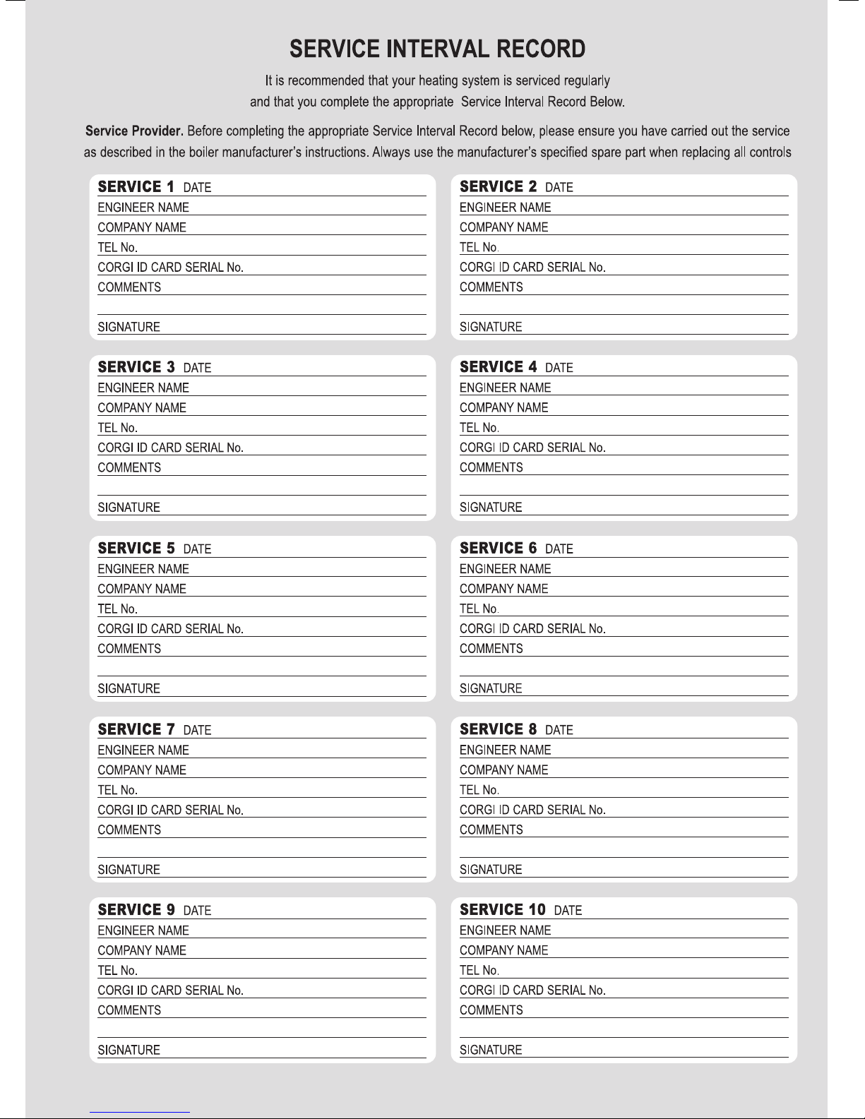
Page 62

Page 63

Page 64

0020031552_03 GB 052008
 Loading...