

Vaillant ecoTEC plus 618, ecoTEC plus 824, ecoTEC plus 624, ecoTEC plus 637, ecoTEC plus 831 Instructions For Installation And Servicing
...Page 1

Supplied By www.heating spares.co Tel. 0161 620 6677
For the installer
Instructions for installation and servicing
ecoTEC
Wall hung room sealed fan assisted condensing boiler
ecoTEC plus 612
ecoTEC plus 615
ecoTEC plus 618
ecoTEC plus 624
ecoTEC plus 630
ecoTEC plus 637
ecoTEC plus 824
ecoTEC plus 831
ecoTEC plus 837
ecoTEC pro 28
ecoTEC pro 24
GB
Page 2

Supplied By www.heating spares.co Tel. 0161 620 6677
Contents
Contents
1 Introduction . . . . . . . . . . . . . . . . . . . . . . . . . . 4
1.1 Notes on the documentation . . . . . . . . . . . . . . . . 4
1.1.1 Applicable documents . . . . . . . . . . . . . . . . . . . . . . 4
1.1.2 Retention of documents . . . . . . . . . . . . . . . . . . . . 4
1.1.3 Safety instructions and symbols . . . . . . . . . . . . . 4
1.2 Introduction . . . . . . . . . . . . . . . . . . . . . . . . . . . . . . 4
1.3 General Notes . . . . . . . . . . . . . . . . . . . . . . . . . . . . . 4
1.4 CE marking . . . . . . . . . . . . . . . . . . . . . . . . . . . . . . . 5
1.5 Gas council numbers . . . . . . . . . . . . . . . . . . . . . . . 5
2 Boiler specifications . . . . . . . . . . . . . . . . . . . 6
2.1 Technical data . . . . . . . . . . . . . . . . . . . . . . . . . . . . . 6
2.2 Dimensions . . . . . . . . . . . . . . . . . . . . . . . . . . . . . . . 8
2.4 Installation . . . . . . . . . . . . . . . . . . . . . . . . . . . . . . . . 9
2.5 Type plate . . . . . . . . . . . . . . . . . . . . . . . . . . . . . . . . 9
3 General requirements . . . . . . . . . . . . . . . . . . 10
3.1 Preliminary remarks for room sealed
appliances . . . . . . . . . . . . . . . . . . . . . . . . . . . . . . . . 10
3.2 Related documents . . . . . . . . . . . . . . . . . . . . . . . . 10
3.3 Contents included with delivery . . . . . . . . . . . . . 10
3.4 Installation site . . . . . . . . . . . . . . . . . . . . . . . . . . . . 12
3.5 Gas supply . . . . . . . . . . . . . . . . . . . . . . . . . . . . . . . . 13
3.6 Flue pipe . . . . . . . . . . . . . . . . . . . . . . . . . . . . . . . . . 13
3.6.1 Standard 100 mm flue system . . . . . . . . . . . . . . . 13
3.6.2 Optional 125 mm flue system . . . . . . . . . . . . . . . . 13
3.7 Flue termination . . . . . . . . . . . . . . . . . . . . . . . . . . . 14
3.8 Air supply . . . . . . . . . . . . . . . . . . . . . . . . . . . . . . . . 14
3.9 Electrical supply . . . . . . . . . . . . . . . . . . . . . . . . . . . 15
3.10 Guide to system requirements . . . . . . . . . . . . . . . 15
3.10.1 Water circulation system . . . . . . . . . . . . . . . . . . . 15
3.10.2 Filling and preparing heating system . . . . . . . . . 15
3.10.3 Pressure relief valve . . . . . . . . . . . . . . . . . . . . . . . 15
3.10.4 Pressure gauge . . . . . . . . . . . . . . . . . . . . . . . . . . . . 15
3.10.5 Expansion vessel . . . . . . . . . . . . . . . . . . . . . . . . . . 15
3.11 Pump specifications . . . . . . . . . . . . . . . . . . . . . . . 16
3.11.1 Circulating pump . . . . . . . . . . . . . . . . . . . . . . . . . . 16
3.11.2 System by-pass . . . . . . . . . . . . . . . . . . . . . . . . . . . . 16
3.11.3 Venting . . . . . . . . . . . . . . . . . . . . . . . . . . . . . . . . . . . 16
3.12 Condensate trap . . . . . . . . . . . . . . . . . . . . . . . . . . . 16
4 Boiler installation sequence . . . . . . . . . . . . . 16
4.1 Transporting the appliance . . . . . . . . . . . . . . . . . 16
4.2 Required minimum distances/assembly
clearances . . . . . . . . . . . . . . . . . . . . . . . . . . . . . . . . 18
4.2.1 Select position for boiler . . . . . . . . . . . . . . . . . . . 18
4.2.2 Unpack the boiler . . . . . . . . . . . . . . . . . . . . . . . . . . 18
4.2.3 Using boiler template . . . . . . . . . . . . . . . . . . . . . . 19
4.3 Flue exit . . . . . . . . . . . . . . . . . . . . . . . . . . . . . . . . . . 20
4.4 Fitting the boiler hanging bracket . . . . . . . . . . . 20
4.5 Installing the flue system . . . . . . . . . . . . . . . . . . . 20
4.6 Fitting the boiler . . . . . . . . . . . . . . . . . . . . . . . . . . 20
4.7 Removing the front case . . . . . . . . . . . . . . . . . . . 20
4.8 General instructions for heating system . . . . . . 20
4.9 Gas connection . . . . . . . . . . . . . . . . . . . . . . . . . . . . 21
4.10 Cold water mains inlet and hot water outlet
(ecoTEC combination boilers only) . . . . . . . . . . . 21
4.11 Condensate drain pipe . . . . . . . . . . . . . . . . . . . . . 22
4.12 Heating connection . . . . . . . . . . . . . . . . . . . . . . . 23
4.12.1 Heating flow and return connection . . . . . . . . . . 23
4.12.2 Pressure Relief Valve . . . . . . . . . . . . . . . . . . . . . . . 24
4.13 Connecting the flue system to the boiler . . . . . 24
4.14 Electrical connection . . . . . . . . . . . . . . . . . . . . . . . 24
4.14.1 General requirements . . . . . . . . . . . . . . . . . . . . . . 24
4.14.2 Connection to the main supply . . . . . . . . . . . . . . 25
4.14.3 Electric board layout . . . . . . . . . . . . . . . . . . . . . . . 26
4.15 Controls . . . . . . . . . . . . . . . . . . . . . . . . . . . . . . . . . . 29
4.15.1 Vaillant controls and accessories . . . . . . . . . . . . 29
4.15.2 External electrical controls . . . . . . . . . . . . . . . . . 29
4.15.3 Connection details for external time switches
and boiler terminal strip . . . . . . . . . . . . . . . . . . . . 29
4.15.4 Vaillant optional plug in timer accessories . . . . 29
4.15.5 Connection details using the VR 65 Control
Center . . . . . . . . . . . . . . . . . . . . . . . . . . . . . . . . . . . . 29
4.16 Thermostatic radiator valves . . . . . . . . . . . . . . . . 29
4.17 Frost protection . . . . . . . . . . . . . . . . . . . . . . . . . . . 30
4.18 Circulating pump . . . . . . . . . . . . . . . . . . . . . . . . . . 30
4.19 Anticycling ‘economiser’ control . . . . . . . . . . . . . 30
4.20 Automatic pump spin control (APS) . . . . . . . . . . 30
5 Commissioning Part I . . . . . . . . . . . . . . . . . . 30
5.1 Preliminary electrical checks . . . . . . . . . . . . . . . . 30
5.2 Gas supply . . . . . . . . . . . . . . . . . . . . . . . . . . . . . . . . 30
5.3 Cold water supply (ecoTEC combination
boilers only) . . . . . . . . . . . . . . . . . . . . . . . . . . . . . . 30
5.4 Filling and bleeding the heating system . . . . . . 30
5.4.1 Checking the filling pressure of the heating
system . . . . . . . . . . . . . . . . . . . . . . . . . . . . . . . . . . . 31
5.4.2 ecoTEC plus combination boiler filling loop . . . 31
5.4.3 Filling the heating system in ecoTEC pro
combination boilers and ecoTEC plus system
boilers . . . . . . . . . . . . . . . . . . . . . . . . . . . . . . . . . . . 32
5.4.4 Filling the heating system for the first time . . . 32
5.5 Initial system flush (“cold”) . . . . . . . . . . . . . . . . . 32
5.6 Filling the condensate siphon . . . . . . . . . . . . . . . 32
5.7 Adjusting the pumping capacity . . . . . . . . . . . . . 33
5.8 Adjusting the by-pass . . . . . . . . . . . . . . . . . . . . . . 33
5.9 Checking the gas supply . . . . . . . . . . . . . . . . . . . . 33
5.9.1 Factory settings . . . . . . . . . . . . . . . . . . . . . . . . . . . 33
5.9.2 Gas inlet working pressure . . . . . . . . . . . . . . . . . . 33
5.9.3 Checking the gas rate . . . . . . . . . . . . . . . . . . . . . . 34
5.10 Refitting the case . . . . . . . . . . . . . . . . . . . . . . . . . . 34
5.11 Adjusting the central heating output (range
rating) . . . . . . . . . . . . . . . . . . . . . . . . . . . . . . . . . . . . 35
5.12 Gas changeover . . . . . . . . . . . . . . . . . . . . . . . . . . . 35
6 Functional checks (commissioning part II) . 35
6.1 Functional checks . . . . . . . . . . . . . . . . . . . . . . . . . . 35
6.1.1 Procedure . . . . . . . . . . . . . . . . . . . . . . . . . . . . . . . . 35
6.1.2 Heating . . . . . . . . . . . . . . . . . . . . . . . . . . . . . . . . . . . 36
6.1.3 Water heating (combination boilers only) . . . . . 36
6.1.4 Final flush of the heating system (“hot”) . . . . . 36
6.2 Handing over to the user . . . . . . . . . . . . . . . . . . . 36
6.3 Vaillant warranty . . . . . . . . . . . . . . . . . . . . . . . . . . 37
2
Instructions for installation and servicing ecoTEC
Page 3

Supplied By www.heating spares.co Tel. 0161 620 6677
7 Inspection and maintenance . . . . . . . . . . . . 37
7.1 Initial inspection . . . . . . . . . . . . . . . . . . . . . . . . . . . 37
7.1.1 Safety instructions . . . . . . . . . . . . . . . . . . . . . . . . . 37
7.1.2 Maintenance . . . . . . . . . . . . . . . . . . . . . . . . . . . . . . 38
7.1.3 Overview of the inspection and maintenance
tasks . . . . . . . . . . . . . . . . . . . . . . . . . . . . . . . . . . . . . 38
7.1.4 Functional check of boiler operation . . . . . . . . . 38
7.2 Servicing the burner module . . . . . . . . . . . . . . . . 39
7.2.1 Removing the burner module . . . . . . . . . . . . . . . 39
7.2.2 Cleaning the integral condensation heat
exchanger . . . . . . . . . . . . . . . . . . . . . . . . . . . . . . . . 39
7.2.3 Checking the burner . . . . . . . . . . . . . . . . . . . . . . . 40
7.2.4 Refitting the burner module . . . . . . . . . . . . . . . . 40
7.3 Cleaning the condensate siphon . . . . . . . . . . . . . 41
7.4 Checking the expansion vessel . . . . . . . . . . . . . . 42
7.5 Recommissioning the boiler . . . . . . . . . . . . . . . . . 42
7.6 Test operation . . . . . . . . . . . . . . . . . . . . . . . . . . . . . 42
8 Troubleshooting . . . . . . . . . . . . . . . . . . . . . . . 42
8.1 Logical fault finding procedure . . . . . . . . . . . . . . 42
8.1.1 Status codes . . . . . . . . . . . . . . . . . . . . . . . . . . . . . . 43
8.1.2 Diagnostic codes . . . . . . . . . . . . . . . . . . . . . . . . . . 43
8.1.3 Fault codes . . . . . . . . . . . . . . . . . . . . . . . . . . . . . . . 46
8.1.4 Fault memory . . . . . . . . . . . . . . . . . . . . . . . . . . . . . 46
8.4 Test programs . . . . . . . . . . . . . . . . . . . . . . . . . . . . . 48
8.5 Resetting parameter to factory settings . . . . . . 48
Contents
9 Parts replacement . . . . . . . . . . . . . . . . . . . . . 48
9.1 Safety instructions . . . . . . . . . . . . . . . . . . . . . . . . . 48
9.2 Replacing burner . . . . . . . . . . . . . . . . . . . . . . . . . . 48
9.3 Replacing fan or gas valve . . . . . . . . . . . . . . . . . . 49
9.4 Replacing expansion vessel . . . . . . . . . . . . . . . . . 49
9.5 Replacing primary heat exchanger . . . . . . . . . . . 50
9.6 Replacing electronics and display . . . . . . . . . . . . 51
9.7 Check CO
(air-ratio adjustment) . . . . . . . . . . . . . . . . . . . . . . 51
10 Recycling and disposal . . . . . . . . . . . . . . . . . 52
11 Vaillant service . . . . . . . . . . . . . . . . . . . . . . . 52
Appendix
EG declaration of conformity . . . . . . . . . . . . . . . . 53
Benchmark gas boiler commissioning
checklist . . . . . . . . . . . . . . . . . . . . . . . . . . . . . . . . . . 54
content and if necessary set
2
3Instructions for installation and servicing ecoTEC
Page 4
Supplied By www.heating spares.co Tel. 0161 620 6677
1 Introduction
1 Introduction
1.1 Notes on the documentation
The following information is intended to help you
throughout the entire documentation.
Further documents apply in combination with this installation and maintenance manual.
We assume no liability for any damage caused by
non-observance of these manuals.
1.1.1 Applicable documents
The following additional documents are provided with
the appliance:
For the owner of the system:
Instructions for use Nr. 838402
Brief users instructions
(only ecoTEC plus) no. 838404
Warranty card with return envelope no. 802922
For the qualified technician:
Instructions for installation and servicing no. 839592
Flue installation instructions no. 834449
The manuals for any accessories and controllers used
also apply.
1.1.2 Retention of documents
Please pass on this installation manual to the owner of
the system. The owner should retain the manuals so that
they are available when required.
1.1.3 Safety instructions and symbols
Please observe the safety instructions in this manual for
the installation of the appliance!
Symbols used in the manual are explained below:
1.2 Introduction
Note
This boiler must be installed and serviced by a
competent person in accordance with the Gas
Safety (Installation and Use) Regulations 1998.
In the UK ‘CORGI’ registered installers undertake the work in compliance with safe and satisfactory standard.
ecoTEC combination boiler
The ecoTEC combination boiler is a fully automatic, wall
mounted, room sealed condensing (high efficiency) boiler for central heating and domestic hot water.
Domestic hot water is supplied directly from the boiler,
without requiring a copper cylinder, cold water tank,
feed and expansion vessel and associated pipework.
Domestic hot water has priority over central heating.
The ecoTEC plus combination boiler consists of 3 models
with outputs of 23 kW, 31 kW and 37 kW for domestic hot
water and two pro versions with outputs of 24 kW and
28 kW for domestic hot water.
All versions are available in natural gas. The ecoTEC plus
831 is also available in LPG.
ecoTEC combination boilers incorporate a warm start
facility that keeps the domestic hot water heat exchanger hot, providing an instantaneous delivery of domestic
hot water. The temperature in the domestic hot water
heat exchanger is limited by the boiler control system
and it is not necessary to install a scale reducer on the
cold mains to the boiler. However, in areas that get
exceptionally hard water, a scale reducer may be fitted
to prevent scale formation in the hot water system
pipes. The heating system on ecoTEC plus combination
boilers can be filled using the built–in filling loop contained within the boiler.
Danger!
Immediate danger to life and limb!
Danger!
Risk of death from electric shock!
Danger!
Risk of burns or scalding!
Caution!
Potentially dangerous situation for the product
and environment!
Note
Useful information and instructions.
• Symbol for a necessary task
4 Instructions for installation and servicing ecoTEC
ecoTEC system boiler
The ecoTEC system boiler is a fully automatic, wall
mounted, room sealed condensing (high efficiency) boiler for central heating and domestic hot water (where a
separate indirect hot water storage cylinder is also
incorporated in the system). The ecoTEC system boiler
consists of models with outputs of 12, 15, 18, 24, 30 and
37 kW. All ecoTEC system boilers are available in Natural
Gas. The ecoTEC plus 618 and 630 are also available in
LPG.
1.3 General Notes
The boilers have been designed for use with a sealed
central heating system, and come fully tested and
assembled with a built in circulating pump, expansion
vessel and diverter valve (ecoTEC combination boilers).
The boilers are easily mounted on any internal wall and
can be installed with either a horizontal or vertical RSF
(room sealed fan assisted) flue.
The boilers use a standard flue system (100 mm or
125 mm outside diameter). Flue extensions and additional bends and elbows are available for the flue system to
Page 5
Supplied By www.heating spares.co Tel. 0161 620 6677
Introduction 1
increase the flexibility. If desired, an inhibitor may be
used in the system. Guidance on the use of inhibitors is
contained in these instructions.
All boilers have a built in diagnostic system which indicates the operational status of the boiler. This feature
provides key information to aid commissioning and fault
finding. The data badge is fitted to the underside of the
boiler. See text of General Requirements for installation
requirements or notes.
The Valliant ecoTEC are state-of-the-art appliances
which have been constructed in accordance with recognised safety regulations. Nevertheless, danger to the life
and limb of the user or third parties can still occur or
the appliance or other material assets be damaged in
the event of improper use.
The appliance is designed to generate heat for connecting to hot water central heating systems and for instantaneous hot water supply (ecoTEC combination boilers
only). Any other use or extended use is considered to be
use other than intended. The manufacturer/supplier is
not liable for any resulting damage.
Intended use includes the observance of the operating
and installation manual and the adherence to the inspection and maintenance conditions.
Danger!
Any incorrect use is forbidden.
1.5 Gas council numbers
Applaince Gas council numbers
ecoTEC pro 24 47-044-36
ecoTEC pro 28 47-044-30
ecoTEC plus 824 47-044-31
ecoTEC plus 831 47-044-32
ecoTEC plus 831 Propane 47-044-34
ecoTEC plus 837 47-044-33
ecoTEC plus 612 41-044-44
ecoTEC plus 615 41-044-45
ecoTEC plus 618 41-044-46
ecoTEC plus 618 Propane 41-044-51
ecoTEC plus 624 41-044-47
ecoTEC plus 630 41-044-48
ecoTEC plus 630 Propane 41-044-50
ecoTEC plus 637 41-044-49
Table 1.1 Gas council numbers
The appliances must be installed by a competent person,
who is responsible for adhering to the existing regulations, rules and guidelines.
1.4 CE marking
The CE marking shows that the appliances comply
with the basic requirements of the following directives:
- Gas appliances directive (90/396/EEC)
- Electromagnetic compatibility directive with threshold
class B (89/336/EEC)
- Low voltage directive (73/23/EEC)
The appliances satisfy the basic requirements of the efficiency directive (92/42/EEC) as condensing appliance.
- The Gas Applaince (Safety) Regulations 1992
- The boiler (Efficiency) Regulations 1993
Vaillant Ltd. supports the Benchmark initiative.
At the rear of this guide, you will find a
Benchmark gas boiler commissioning checklist.
It is very important that this is completed correctly at the time of installation, commissioning and hand over to the user.
5Instructions for installation and servicing ecoTEC
Page 6
Supplied By www.heating spares.co Tel. 0161 620 6677
2 Boiler specifications
2 Boiler specifications
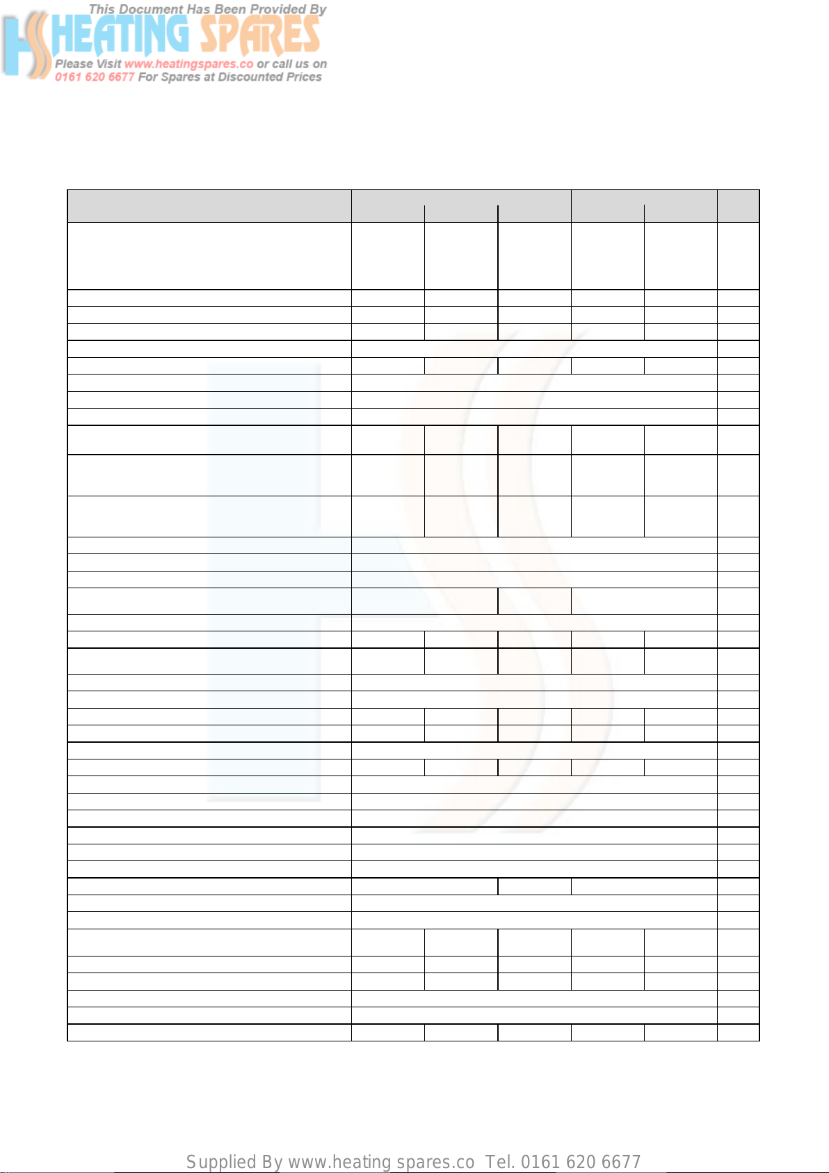
2.1 Technical data
Technical data
CH heat output range
80 °C flow/60 °C return
60 °C flow/40 °C return
50 °C flow/30 °C return
40 °C flow/30 °C return
Maximum DHW output 23.0 31.0 37 23.0 28.0 kW
Maximum output for heating 19 24 28 19 24 kW
Minimum output 6.7 8.7 12 6.7 9.0 kW
Category II
SEDBUK Band A A A A A Band
SAP Seasonal Efficiency 91.1 %
Inlet gas working pressure required (G20, natural gas) 20 mbar
Inlet gas working pressure required (G31, Propane) 37 mbar
Connected load (if needed, related to stored charge/
water heating) at 15 °C and 1013 mbar
Exhaust mass rate
at minimum thermal load (40 °C flow/30 °C return)
at maximum thermal load (80 °C flow/60 °C return)
Exhaust temperature
at minimum thermal load (40 °C flow/30 °C return)
at maximum thermal load (80 °C flow/60 °C return)
NOx class 5
Protection class IP X4D
max. flow temperature 85 °C
Adjustable flow temperature
Default setting: max. 75 °C
Maximum CH system pressure 3.0 bar
Circulation water volume (∆T=20 K)
Approx. condensation volume
at 50 °C flow/30 °C return heating
Pump delivery height 250 mbar
Minimum DHW flow rate 1.5 l/min
DHW flow rate ∆T=35 K rise
Appr. DHW flow rate at factory set temp. rise (∆T=42 K)
Permitted DHW overpressure 10 bar
Mains water pressure required for max. flow rate 0.5 0.75 0.75 0.5 0.5 bar
Mains water pressure required for min. flow rate 0.15 bar
Hot water discharge temperature range 35 – 65 °C
Exhaust flue 60/100 mm
Flue categories C13, C33, C43, C53, C83, B23, B33
10 l expansion vessel pre-charge pressure 0.75 bar
Connections heating flow/return 22 mm
Gas inlet 15 22 15 mm
Pressure relief discharge pipework (min.) 15 mm
Condensate drain (min. internal drain) 19 mm
Dimensions (H x W x D)
Weight (boiler only) 35 38 43 34 37 kg
Primary water content 1.9 2.3 2.5 1.9 2.1 l
Electrical supply voltage 230/50 V ~/Hz
Internal fuse (slow) main voltage 2 A
Power input 110 125 140 110 115 W
Table 2.1 Technical data ecoTEC combination boiler
824 831 837 24 28
6.7 – 19.0
6.9 – 19.6
7.1 – 20.2
7.2 – 20.6
G20: 2.5
G31: 1.82
3.2
10.7
40
74
817 1032 1204 817 1032 l/h
1.8 2.2 2.9 1.8 2.2 l/h
9.4 12.7 15.2 9.4 11.5 l/min
7.9 10.6 12.6 7.9 9.6 l/min
720 x 440 x
335
ecoTEC plus ecoTEC pro
8.7 – 24.0
9.0 – 24.7
9.2 – 25.5
9.4 – 26.0
G20: 3.3
G31: 2.46
4.2
14.4
40
83
30 – 85 40 – 85 30 – 85 °C
720 x 440 x
335
12.0 – 28.0
12.3 – 28.9
12.7 – 29.7
12.9 – 30.3
2H3P
G20: 4.0
G31: 2.94
5.7
17.1
40
70
720 x 440 x
403
6.7 – 19.0
6.9 – 19.6
7.1 – 20.2
7.2 – 20.6
G20: 2.5
G31: 1.82
3.2
10.7
40
74
720 x 440 x
335
9.0 – 24.0
9.3 – 24.7
9.6 – 25.5
9.8 – 26.0
G20: 3.0
G31: 2.22
4.4
13.0
40
74
720 x 440 x
335
Units
kW
kW
kW
kW
m
kg/h
g/s
g/s
°C
°C
mm
3
/h
6 Instructions for installation and servicing ecoTEC
Page 7
Supplied By www.heating spares.co Tel. 0161 620 6677
Boiler specifications 2
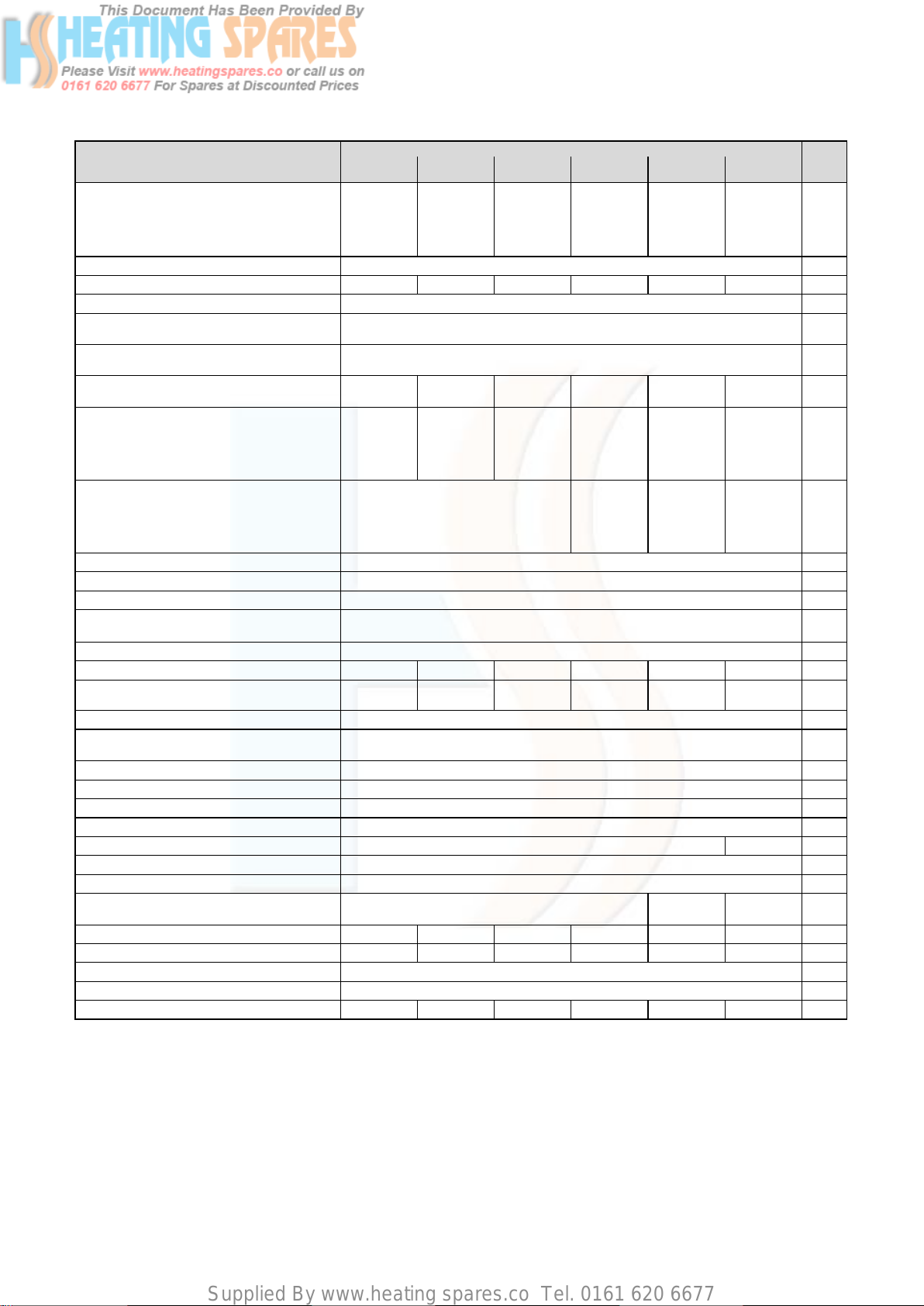
Technical data
CH heat output range
80 °C flow/60 °C return
60 °C flow/40 °C return
50 °C flow/30 °C return
40 °C flow/30 °C return
Category II
SEDBUK Band AAAAAABand
SAP Seasonal Efficiency 91.2 %
Inlet gas working pressure required (G20,
natural gas)
Inlet gas working pressure required (G31,
Propane)
Connected load (if needed, related to stored
charge/water heating) at 15 °C and 1013 mbar
Exhaust mass rate
at minimum thermal load (40 °C flow/30 °C
return
at maximum thermal load (80 °C flow/60 °C
return)
Exhaust temperature
at minimum thermal load (40 °C flow/30 °C
return)
at maximum thermal load (80 °C flow/60 °C
return)
NOx class 5
Protection class IP X4D
max. flow temperature 85 °C
Adjustable flow temperature
Default setting: max. 75 °C
Maximum CH system pressure 3.0 bar
Circulating water volume (∆T=20 K)
Approx. condensation volume
at 50 °C flow/30 °C return heating
Pump delivery height 250 mbar
Adjustable storage target value (15 °C at left
stop, spare adjusting range 40 – 70 °C
Exhaust flue 60/100 mm
Flue categories C13, C33, C43, C53, C83, B23, B33
10 l expansion vessel pre-charge pressure 0.75 bar
Connections heating flow/return 22 mm
Gas inlet 15 22 mm
Pressure relief discharge pipework (min.) 15 mm
Condensate drain (min. internal drain) 19 mm
Dimensions (H x W x D) 720 x 440 x 335
Weight (boiler only) 35 35 35 37 38 40 kg
Primary water content 1.9 1.9 1.9 2.1 2.3 2.5 l
Electrical supply voltage 230/50 V ~/Hz
Internal fuse (slow) main voltage 2 A
Power input 100 110 100 110 110 140 W
Table 2.2 Technical data ecoTEC system boiler
612 615 618 624 630 637
4.9 – 12.0
5.1 – 12.3
5.2 – 12.7
5.3 – 12.9
G20: 1.3
G31: 0.95
2.3
5.6
516 645 774 1032 1290 1591 l/h
1.1 1.4 1.7 2.2 2.7 3.8 l/h
4.9 – 15.0
5.1 – 15.5
5.2 – 15.9
5.3 – 16.2
G20: 1.6
G31: 1.19
2.3
7. 0
40
70
ecoTEC plus
6.7 – 18.0
6.9 – 18.6
7.1 – 19.1
7.2 – 19.5
G20: 1.9
G31: 1.43
3.2
8.3
8.7 – 24.0
9.0 – 24.7
9.2 – 25.5
9.4 – 26.0
2H3P
20 mbar
37 mbar
G20: 2.6
G31: 1.90
4.2
11.2
40
75
30 – 85 °C
15 – 70 °C
10.0 – 30.0
10.3 – 30.9
10.6 –31.8
10.8 – 32.4
G20: 3.2
G31: 2.38
4.8
13.9
40
83
720 x 440 x
369
12.0 – 37.0
12.3 – 38.2
12.7 – 39.3
12.9 – 40.1
G20: 4.0
G31: 2.94
5.7
17.1
40
70
720 x 440 x
403
Units
kW
kW
kW
kW
3
/h
m
kg/h
g/s
g/s
°C
°C
mm
7Instructions for installation and servicing ecoTEC
Page 8

Supplied By www.heating spares.co Tel. 0161 620 6677
2 Boiler specifications
2.2 Dimensions
440
9
8
7
190
65
241
883
720
642
20
Fig. 2.1 Dimensions in mm
175
35 35
6
10
125
11
12
5
75
45
180
12345
300
ecoTEC plus 630:
334
ecoTEC plus 637,
ecoTEC plus 837:
368
4
3
2
130
1
100100
Legend:
1 Heating return pipe Ø 22 mm
2 Cold water connection Ø 15 mm (combination boilers only)
3 Gas connection Ø 15 mm
4 Hot water connection Ø 15 mm (combination boilers only)
5 Heating flow pipe Ø 22 mm
6 Hanging bracket
7 Flue hole - flue system 60/100
8 Flue hole - flue system 80/125
9 Spacer frame accessory (Art. No.: 308 650)
10 Flue pipe connection
11 Condensate drain connection (Ø 19 mm)
12 Heating system expansion relief valve connection (Ø 15 mm)
Note
With the spacer frame (Art. No 308 650), the
pipes can be run behind the boiler. The distance
of the appliance from the wall thus increases by
65 mm.
8 Instructions for installation and servicing ecoTEC
Page 9
Supplied By www.heating spares.co Tel. 0161 620 6677
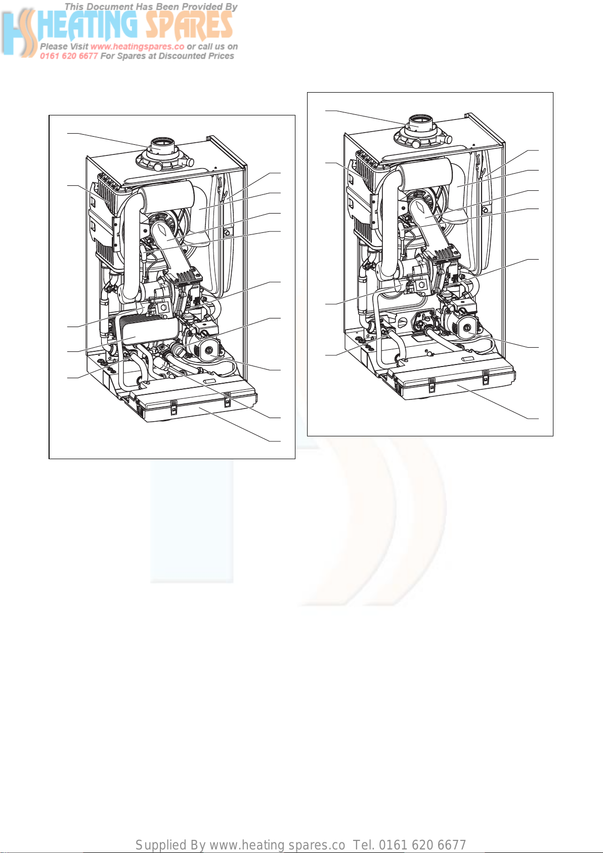
2.4 Installation
14
13
12
Boiler specifications 2
14
1
13
1
2
3
4
5
12
6
2
3
4
5
11
10
Fig. 2.2 Function elements of combination boilers
Legend:
1 Expansion vessel
2 Air intake pipe
3 Burner module
4 Ignition electrode
5 Fan
6 Diverter valve with by-pass
7 Pump
8 Aqua-Sensor
9 Electronics box
10 Pressure sensor
11 Hot water heat exchanger
12 Gas valve
13 Heat exchanger
14 Flue pipe connection
10
7
8
9
Fig. 2.3 Function elements of system boilers
Legend:
1 Expansion vessel
2 Air intake pipe
3 Burner module
4 Ignition electrode
5 Fan
7 Pump
9 Electronics box
10 Pressure sensor
12 Gas valve
13 Heat exchanger
14 Flue pipe connection
7
9
2.5 Type plate
The type plate of the Valliant ecoTEC is attached to the
bottom of the appliance at the factory.
9Instructions for installation and servicing ecoTEC
Page 10
Supplied By www.heating spares.co Tel. 0161 620 6677
3 General requirements
3 General requirements
3.1 Preliminary remarks for room sealed appliances
This appliance should only be installed in conjunction
with either a Vaillant flue system or an alternative
approved system (details of flue approval categories can
be found in the technical section of the installation manual).
Install the flue system as detailed in the separate flue
installation instructions supplied with this boiler.
3.2 Related documents
The installation of the boiler must be in accordance with
the relevant requirements of Gas Safety (Installation and
Use) Regulations 1998, Health and Safety Document No.
635 (The Electricity at Work Regulations 1989), BS7671
(IEE Wiring Regulations) and the Water Supply (Water
Fitting) Regulations 1999, or The Water Bylaws 2000
(Scotland). It should also be in accordance with the relevant requirements of the Local Authority, Building
Regulations, The Building Regulations (Scotland), The
Building Regulations (Northern Ireland) and the relevant
recommendations of the following British Standards:
BS 6700: Services supplying water for domestic use
within buildings and their curtilages.
BS 6798: Specification for installation of gas fired boilers not exceeding 60 kW input.
BS 6891: Specification for installation of low pressure
gas pipework up to 28 mm (R1) in domestic premises
(2nd family gas).
BS 7593: Treatment of water in domestic hot water central heating systems. Institute of Gas Engineers Publication IGE/UP/7/1998: ”Guide for gas installations in timber framed housing”
BS. 5482: Pt. 1 Domestic butane and propane gas burning installations.
IGE/UP1: Soundness testing and purging of industrial and
commercial gas installation.
IGE/UP2: Gas installation pipework, boosters and compressors on industrial and commercial premises.
IGE/UP10. Installation of gas appliances in industrial and
commercial premises.
BS. 6644: Installation of gas fired hot water boilers of
rated inputs between 60 kW and 2 MW (2nd and 3rd family gases).
BS. 5449: Forced circulation hot water central heating
systems for domestic premises. Note: only up to 45 kW.
BS. 6880: Low temperature hot water heating systems
of output greater than 45 kW.
Part 1 Fundamental and design considerations.
Part 2 Selection of equipment.
Part 3 Installation, commissioning and maintenance.
BS. 4814: Specification for: Expansion vessels using an
internal diaphragm, for sealed hot water heating systems.
BS. 5440: Installation and maintenance of flues and ventilation for gas appliances of rated input not exceeding
70 kW net (1st, 2nd and 3rd family gases).
Part 1 Specification for installation of flues.
Part 2 Specification for installation and maintenance
of ventilation for gas appliances.
European installation directive
Important:
The appliance must be installed and serviced by
a competent person as stated in the Gas Safety
(Installation and Use) Regulations 1998. In IE,
the installation must be in accordance with the
current edition of I.S.813 ‘Domestic Gas
Installations’, the current Building Regulations
and reference should be made to the current
ETCI rules for electrical installation.
Important:
When tightening or slackening screwed connections always use suitable open-ended spanners
(not pipe wrench, or extensions, etc.).
Incorrect use and/or unsuitable tools can lead
to damage being caused (e.g. gas or water leakage)!
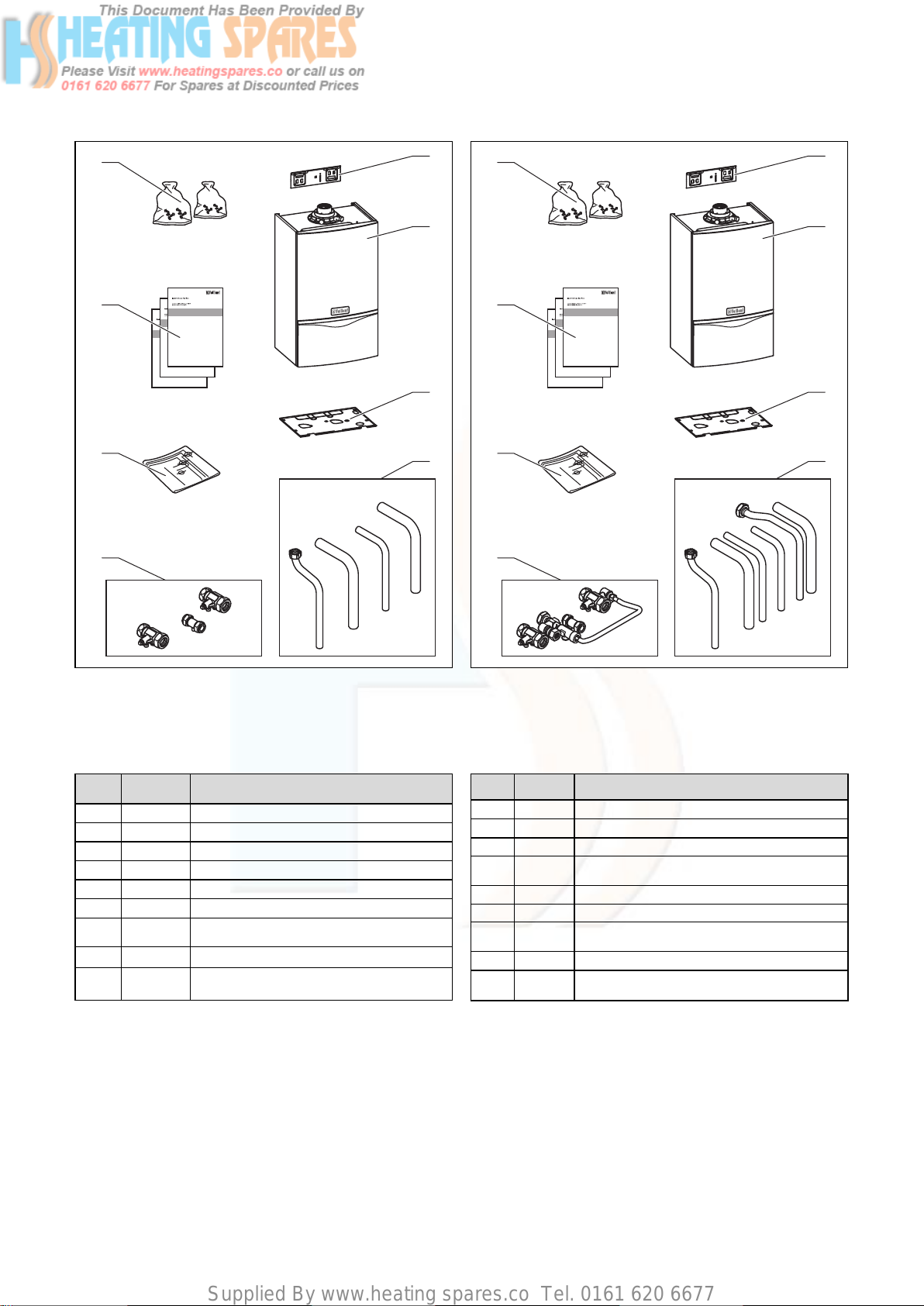
3.3 Contents included with delivery
The Vaillant ecoTEC is delivered pre-mounted in a package unit. Check that all the parts have been delivered
intact (see fig. 3.1 and table 3.1, fig. 3.2 and table 3.2 and
fig. 3.3 and table 3.3).
10 Instructions for installation and servicing ecoTEC
Page 11
Supplied By www.heating spares.co Tel. 0161 620 6677
General requirements 3
8
7
6
5
1
2
3
4
8
7
6
5
1
2
3
4
Fig. 3.1 Contents included with delivery of ecoTEC plus system
boilers
DO NOT remove the boiler from the polystyrene base at
this stage.
Item Quantity Description
1 1 Hanging bracket
2 1 Boiler
3 1 Bottom cover
4 4 Connecting pipes (gas, heating, safety valve)
5 3 Isolating valves
6 1 Template
73
8 2 Installation and connection accessories
Table 3.1 Contents included with delivery of ecoTEC plus system
boilers
User, installation and service and flue installation manuals
For LPG appliances, extra: 1 sticker each for
2
tank and ventilation (above Fig.)
Fig. 3.2 Contents included with delivery of ecoTEC plus combi-
nation boilers
DO NOT remove the boiler from the polystyrene base at
this stage.
Item Quantity Description
1 1 Hanging bracket
2 1 Boiler
3 1 Bottom cover
46
5 4 Isolating valves and filling loop
6 1 Template
73
8 2 Installation and connection accessories
Table 3.2 Contents included with delivery of ecoTEC plus com-
bination boilers
Connecting pipes (gas, heating, water, safety
valve)
User, installation and service and flue installation manuals
For LPG appliances, extra: 1 sticker each for
2
tank and ventilation (above Fig.)
11Instructions for installation and servicing ecoTEC
Page 12
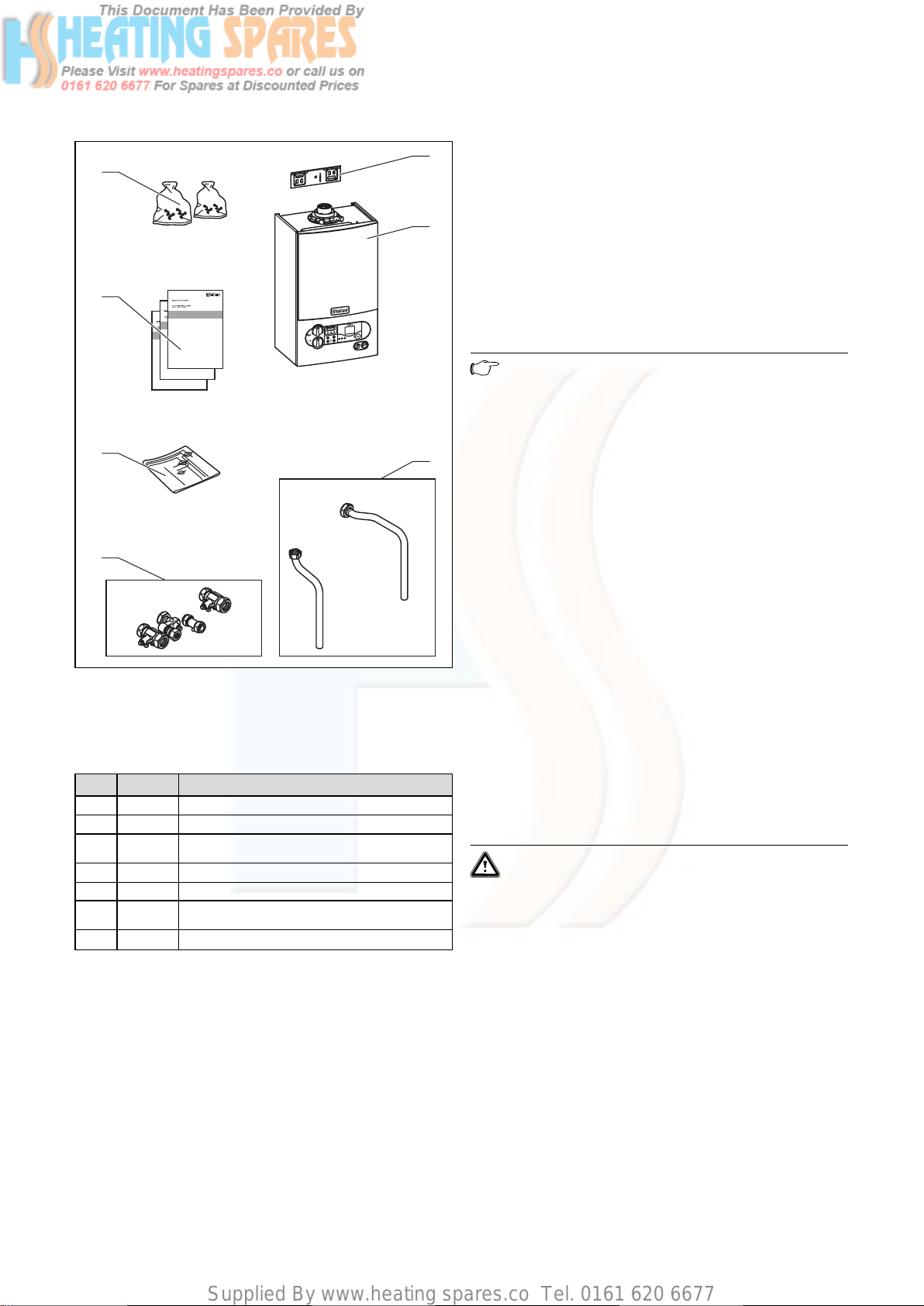
Supplied By www.heating spares.co Tel. 0161 620 6677
3 General requirements
7
6
i F P
r
a
b
5
4
Fig. 3.3 Contents included with delivery of ecoTEC pro combi-
nation boilers
DO NOT remove the boiler from the polystyrene base at
this stage.
Item Quantity Description
1 1 Hanging bracket
2 1 Boiler
32
4 4 Isolating valves
5 1 Template
71
8 2 Installation and connection accessories
Table 3.3 Contents included with delivery of ecoTEC pro combi-
nation boilers
Connecting pipes (hot water, heating safety
valve)
User, installation and service and flue installation manuals
1
2
3
3.4 Installation site
The location chosen for the boiler must permit the provision of a satisfactory flue termination. The location must
also provide adequate space for servicing and air circulation around the boiler. The boiler may be installed in
any room, although particular attention is drawn to the
requirements of BS 7671 (IEE Regulations), the electrical
provisions of the Building Standards (Scotland)
Regulations, and in IE the current edition of IS 813 and
the current ETCI rules, in respect of the installation of a
boiler in a room containing a bath or shower.
Note
If a room sealed boiler is installed in a room
with a bath or shower, electrical switches or
boiler controls using the mains power supply
must be placed at locations that cannot be
reached by the person in the bath or shower.
If the boiler is installed in an unusual location, special
procedures may be necessary and BS 5546 and BS 6798
give detailed guidance on this aspect. The boiler must be
mounted on a flat, vertical wall, which must be sufficiently robust to take the weight of the boiler. The boiler
may be installed on a combustible wall, subject to the
requirements of the Local Authorities and Building
Regulations.
A compartment used to enclose the boiler must be
designed and constructed specifically for this purpose.
(An existing cupboard or compartment may be used provided that it is modified for the purpose). Details of
essential features of cupboard/compartment design
including airing cupboard installations are given in BS
6798. If the boiler is to be fitted in a timber framed
building, it should be fitted in accordance with Institute
of Gas Engineers Publication IGE/UP/7/1998 “Guide for
Gas Installation in Timber Framed Housing”.
Please note the safety instructions below before deciding where to install the boiler:
Caution!
Do not install the appliance in rooms prone to
frost. In rooms with aggressive steam or dust,
the appliance must be operated independent of
the ambient air.
When choosing the place of installation and while operating the appliance, make sure that the air supply is free
of chemical substances containing fluorine, chlorine, sulphur etc. Sprays, solvents and cleaning agents, paints,
adhesives etc. contain the kind of substances that can
lead to corrosion even in the exhaust system when the
appliance is operated depending on the ambient air in
the worst case scenario. Particularly in hair-cutting
salons, lacquering and finishing, cleaning facilities, the
appliance must be operated independent of the ambient
air! Otherwise, a separate installation room is required
to guarantee that the air supply is free of the above
mentioned substances.
12 Instructions for installation and servicing ecoTEC
Page 13
Supplied By www.heating spares.co Tel. 0161 620 6677
3.5 Gas supply
The gas supplier should ensure the availability of an
adequate supply of gas. A gas meter may only be connected to the service pipe by the supplier of gas or their
contractor. An existing meter should be checked to
ensure that it is capable of passing the rate of gas supply required.
Installation pipes should be fitted in accordance with
BS 6891. In IE the current edition of IS 813. Pipework
from the meter to the boiler must be of an adequate
size. Do not use pipes of a smaller size than the boiler
gas connection (15 mm). The complete installation must
be checked for leaks and purged as described in
BS 6891.
General requirements 3
550
10
1435
3.6 Flue pipe
Danger!
Vaillant appliances are certified only for use
with genuine Vaillant flue pipes. Only use genuine Vaillant flue pipes. Malfunctions can occur if
you use other accessories. These may result in
damage and injury. You will find a list of genuine
flue pipes in the Vaillant installation manual for
flue pipes.
The CE mark is valid only if the appliance is
operated with Vaillant flue pipes.
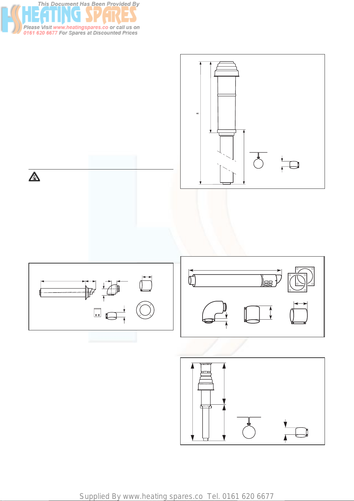
3.6.1 Standard 100 mm flue system
667
87
65
74
30
880
40
Fig. 3.5 Art. No. 303 900
3.6.2 Optional 125 mm flue system
A concentric flue system of 125 mm outside diameter is
available and can be used to achieve flue lengths up to
25 m.
A vertical flue system is also available. Refer to flue system installation instructions for full details.
1103
48
70
70
15
Fig. 3.4 Art. No. 303 933
Fig. 3.6 Art. No. 303 209
A standard 100 mm flue system (Art. No. 303 933) is
available. Refer to flue system installation instructions
for full details.
Flue extensions are available to extend this length up to
8 m. Both 90° bends and 45° elbows are also available
to increase siting flexibility.
Fig. 3.7 Art. No. 303 200
650
1530
880
70
13Instructions for installation and servicing ecoTEC
Page 14
Supplied By www.heating spares.co Tel. 0161 620 6677
3 General requirements
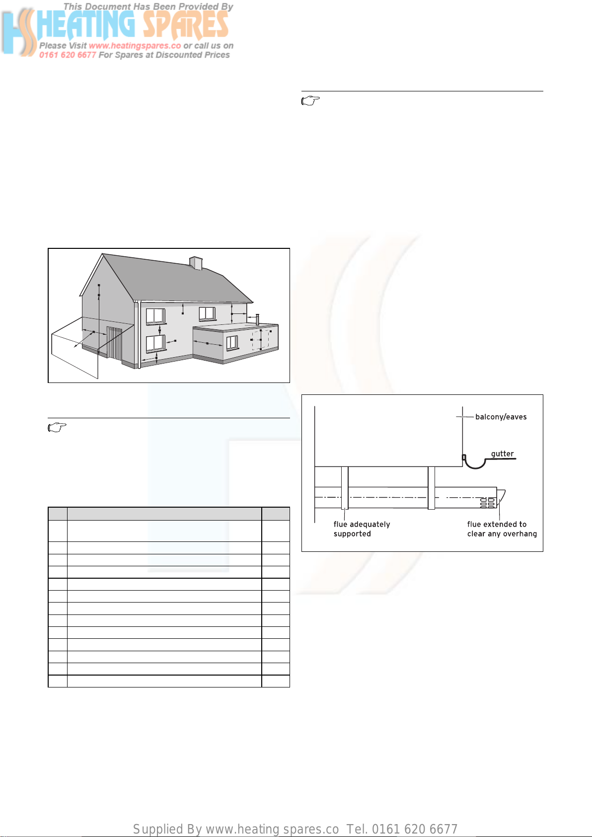
3.7 Flue termination
The following details refer to both flue systems.
a. The terminal must be located where the combustible
substances can escape freely at all times.
b. A plume of water vapour will sometimes be visible
from the flue terminal. Positions where this could be
a nuisance should be avoided.
c. If the terminal is fitted less than 2 m above a balcony,
above ground or above a flat roof to which people
have access then a suitable terminal guard must be
provided and fitted (made by Tower Flue
Components, Tonbridge, TN9 1TB, Model K3, plastic
coated).
A
G
F
J
H, I
Fig. 3.8 Flue termination
BCD
A
A
A
E
G
B
F
M
G
L
F
F
K
K
L
Note
In addition, the terminal should not be nearer
than 150 mm to an opening in the building fabric formed for the purpose of accommodating a
built-in element such as a window.
BS 5440–1: It is recommended that the fanned flue terminal should be positioned as follows:
a) at least 2 m from an opening in the building directly
opposite, and
b) so that the products of combustion are not directed
to discharge across a boundary.
1) Dimensions B, C and D:
These clearances may be reduced to 25 mm without
affecting the performance of the boiler. In order to
ensure that the condensate plume does not affect
adjacent surfaces the terminal should be extended as
shown in Fig. 3.9.
2) Dimension F:
This clearance may be reduced to 25 mm without
affecting the performance of the boiler. However, in
order to ensure that the condensate plume does not
affect adjacent surfaces a clearance of 300 mm is
preferred. For IE, recommendations are given in the
current edition of IS 813.
Note
Vertical flues must not terminate within
600 mm of an openable window, air vent or any
other ventilation opening.
The flue assembly shall be so placed or shielded as to
prevent ignition or damage to any part of the building.
Terminal position mm
Directly below an opening, above an opening or hori-
A
zontal to an opening, air brick, opening window, etc.
B Below gutters, soil pipes or drain pipes 75
C Below eaves 200
D Below balconies 200
E From vertical drain pipes and soil pipes 25
F From internal or external corners 300
G Above ground, roof or balcony 300
H From a surface facing a terminal 600
I From a terminal facing a terminal 1200
J From an opening (e.g. door, window) into the dwelling 1200
K Vertically from a terminal on the same wall 1500
L Horizontally from a terminal on the same wall 300
M Distance from adjacent for vertical Flue 500
Table 3.4 Terminal position for a fan assisted concentric flue
300
Fig. 3.9 Flue termination under balcony/eaves
3.8 Air supply
Detailed recommendations for air supply are given in
BS 5440: Part 2.
It is not necessary to have an air vent in the room or
internal space in which the boiler is installed.
Cupboard or compartment ventilation
The boilers are very high efficiency appliances. As a consequence the heat loss from the appliance casing during
operation is very low. For cupboard or compartment
installations it is therefore not necessary to provide any
high or low level permanent air vents for cooling purposes.
14 Instructions for installation and servicing ecoTEC
Page 15
Supplied By www.heating spares.co Tel. 0161 620 6677
General requirements 3
3.9 Electrical supply
A 230 V, ~ 50 Hz single phase electricity supply fused to
3 Amp. must be provided in accordance with the latest
edition of BS 7671 (IEE Wiring Regulations) and any other
local regulations that may apply. In IE reference should
be made to the current edition of the ETCI rules. The
method of connection to the mains electricity supply
must provide a means of completely isolating the boiler
and its ancillary controls. Isolation is preferably by the
use of a fused three pin plug and unswitched shuttered
socket outlet, both complying with the requirements of
BS 1363. Alternatively, a 3 Amp. fused double pole switch
with a 3 mm contact separation on both poles may be
used.
Danger!
This appliance must be earthed.
3.10 Guide to system requirements
3.10.1 Water circulation system
Detailed recommendations for the water circulation system are given in BS 6798 and BS 5449: Part 1 (for small
bore and micro bore central heating systems). Pipework
not forming part of the useful heating surface should be
insulated to help prevent heat loss and possible freezing,
particularly where pipes are run through roof spaces
and ventilated underfloor spaces. Draining taps must be
located in accessible positions which permit the draining
of the whole system including the boiler and the hot
water system. Draining taps should be at least 1/2 in.
BSP nominal size and be in accordance with BS 2879.
The boiler is suitable for use with minibore or microbore
systems. Copper tubing to BS 2871: Part 1 should be used
for water carrying pipework. All capillary joints in all
DHW pipework must be made with lead free solder.
Particularly where a new boiler is to be fitted to an existing system, it is good practice that the system is thoroughly cleansed.
3.10.2 Filling and preparing heating system
The system can be filled using the built in filling loop
(ecoTEC plus combination boilers only) or via a separate
filling point fitted at a convenient position on the heating circuit. The connection must be removed when filling
is completed. Where local Water Authority regulation
does not allow temporary connection, a sealed system
filler pump with break tank must be used. The heating
system will not be filled automatically from the domestic
hot water side. (Alternative methods of filling sealed systems are given in BS 5449).
3.10.3 Pressure relief valve
A pressure relief valve is provided with the boiler. This
safety device is required on all sealed C.H. systems and
is preset at 3 bar and provided with a 15 mm compression connection for a discharge pipe, which must be of
no less than 15 mm in diameter. The pressure relief valve
must not be used for draining purposes.
3.10.4 Pressure gauge
This is factory fitted to the boiler and indicates the primary circuit pressure to facilitate filling and testing.
3.10.5 Expansion vessel
ecoTEC boilers incorporate a 10 litre expansion vessel
which is suitable for a sealed heating system with a maximum water content of 100 litres.
If the nominal capacity of the built in expansion vessel is
not sufficient for the heating system (for instance in
case of modernisation of old open systems) an additional expansion vessel can be installed external to the boiler. It should be fitted in the return pipe as close as possible to the boiler in accordance with BS 5449: Part 1.
Guidance on the sizing of an additional expansion vessel
is given in Table 3.5.
Important:
To prevent the formation of deposits and prevent serious damage to the appliance and system, cleansers must be used carefully and must
be completely removed by thoroughly flushing
the system. Cleansers should only be left in
systems for a maximum of 24 hours.
This cleansing must take place prior to the fitting of the
new boiler and be in accordance with BS 7593. For
advice on the application of system cleansers contact
Sentinel, Betz Dearborn Ltd. Widnes, Cheshire, WA8
8UD. Tel: 0151 420 9595, or Fernox, Alpha Fry
Technologies, Tandem House, Marlow Way, Croydon, CR0
4XS. Tel 0870 8700362.
15Instructions for installation and servicing ecoTEC
Page 16
Supplied By www.heating spares.co Tel. 0161 620 6677
3 General requirements
4 Boiler installation sequence
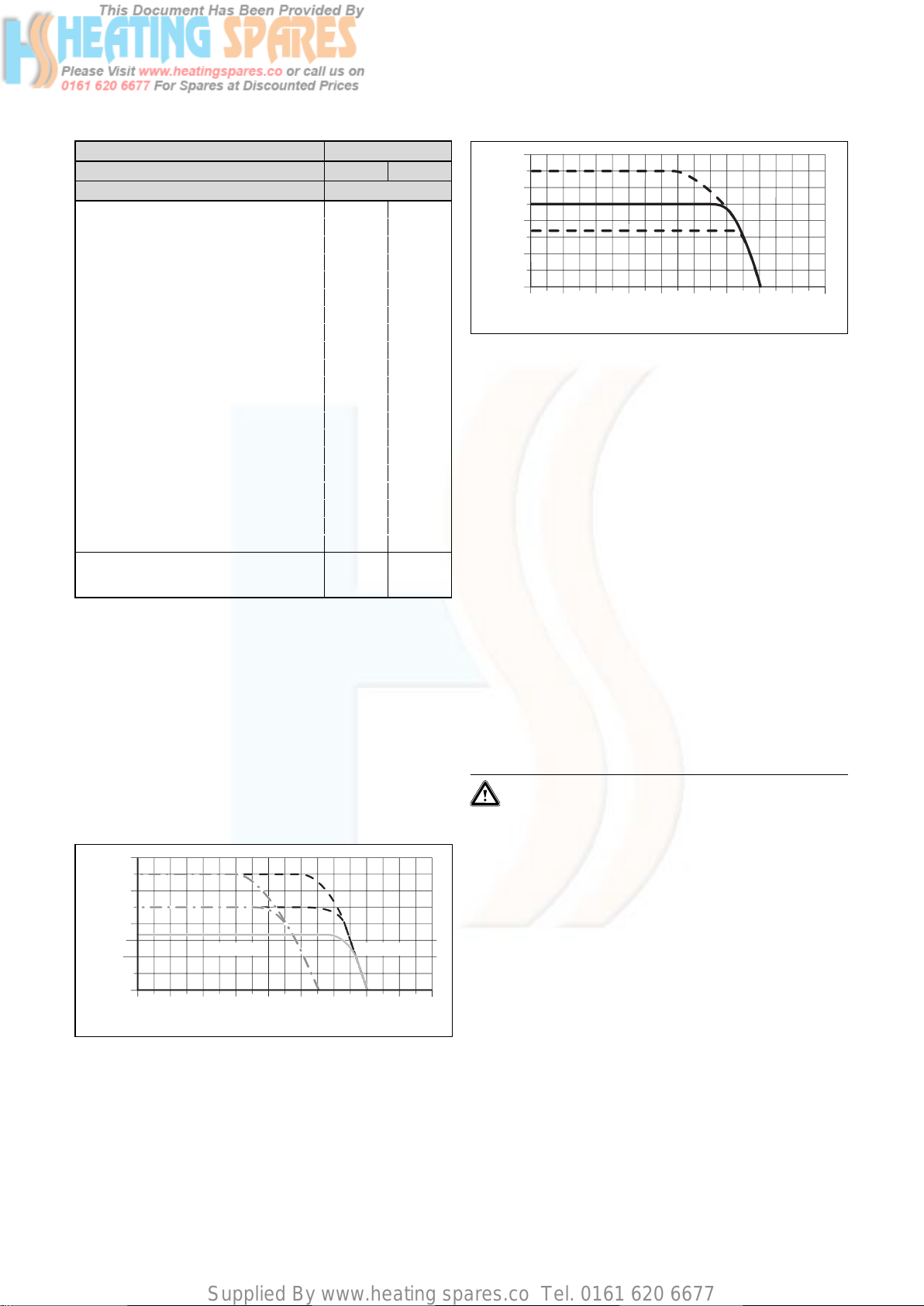
Vessel Volume [L]
Initial system pressure (bar) 1.0 1.5
Pressure relief valve setting (bar) 3.0
Total water content of system litres
25 2.7 3.9
50 5.4 7.8
100 10.9 15.6
125 13.6 19.5
150 16.3 23.4
175 19.1 27.3
200 21.8 31.2
225 24.5 35.1
250 27.2 39.0
275 30.0 42.9
300 32.7 46.8
325 35.7 50.7
350 38.1 54.6
375 40.9 58.5
400 43.6 62.4
425 46.3 66.3
450 49.0 70.2
475 51.8 74.1
500 54.5 78.0
For system volumes other than those given
above, multiply the system volume by the
factor across
Table 3.5 Sizing of additional expansion vessel
0.109 0.156
3.11 Pump specifications
]
400
mbar
[
300
Lift
200
100
0
0 200 400 600 800 1000 1200 1600
Fig. 3.11 Pump specifications ecoTEC pro
1400
Volumeflow [l/h
1800
]
3.11.2 System by-pass
An automatic system by-pass is provided in the boiler.
The boiler is suitable for use in systems with thermostatic radiator valves and no additional by-pass is required.
The by-pass valve is adjustable, see section 5.8.
3.11.3 Venting
The boiler is fitted with an automatic air vent. Additional
provision should be made to enable the heating system
to be vented during filling and commissioning either by
automatic air vents or manually.
3.12 Condensate trap
The boiler is fitted with a siphonic condensate discharge
(ecoTEC plus) or a condensate trap (ecoTEC pro) incorporating a water trap of 140 mm.
3.11.1 Circulating pump
only ecoTEC plus:
The circulating pump is included in the boiler. The residual pump discharge height depending on the by-pass
valve is shown in Fig. 3.10.
The operating mode of the 2-step pump can be adjusted
below the diagnosis number “d.19”, see section 8.1.2.
]
400
mbar
[
300
Lift
200
100
0
0 200 400 600 800 1000 1200 1600
Fig. 3.10 Pump specifications ecoTEC plus
2. Step1. Step
1400
Volumeflow [l/h
1800
]
only ecoTEC pro:
The circulating pump is included in the boiler. The ecoTEC pro appliances are fitted with a single-stage pump.
The residual pump discharge height depending on the
by-pass valve is shown in Fig. 3.11.
4 Boiler installation sequence
4.1 Transporting the appliance
Important:
With regards to the Manual Handling
Operations, 1992 Regulations, the following lift
operation exceeds the recommended weight for
a one man lift.
General recommendations when handling
Clear the route before attempting the lift.
Ensure safe lifting techniques are used – keep back
straight – bend using legs. Keep load as close to body as
possible. Do not twist – reposition feet instead. If 2 persons performing lift, ensure co-ordinated movements
during lift. Avoid upper body/top heavy bending - do not
lean forward/sideways. Recommend wear suitable cut
resistant gloves with good grip to protect against sharp
edges and ensure good grip. Always use assistance if
required.
Removal of carton from delivery van
Recommend 2 person lift or 1 person with use of sack
truck. If 1 person is performing lift, straddle the load, tilt
and place carton into position on truck. Recommend
secure appliance onto truck with suitable straps. Ensure
16 Instructions for installation and servicing ecoTEC
Page 17

Supplied By www.heating spares.co Tel. 0161 620 6677
Boiler installation sequence 4
safe lifting techniques are used – keep back straight –
bend using legs. Keep load as close to body as possible.
If 2 persons performing lift, ensure co-ordinated movements during lift. Always use assistance if required.
Carriage of carton from point of delivery to point of
installation – ground floor.
Recommend 2 person lift or 1 person with use of sack
truck. If 1 person is performing lift, straddle the load, tilt
and place carton into position on truck. Recommend
secure appliance onto truck with suitable straps. Ensure
safe lifting techniques are used – keep back straight –
bend using legs. Keep load as close to body as possible.
If 2 persons performing lift, ensure co-ordinated movements during lift. Clear the route before attempting the
lift. If removing boiler from truck straddle the load and
tilt forwards to facilitate secure grip. Ensure safe lifting
techniques are used – keep back straight – bend using
legs. Do not twist – reposition feet instead. Take care to
avoid trip hazards, slippery or wet surfaces and when
climbing steps and stairs. Always use assistance if
required.
Carriage of carton from point of delivery to point of
installation – first or higher floor, cellar.
Recommend 2-person lift or 1 person with use of sack
truck. If 1 person is performing lift, straddle the load, tilt
and place carton into position on truck. Recommend
secure appliance onto truck with suitable straps. Ensure
safe lifting techniques are used – keep back straight –
bend using legs. Keep load as close to body as possible.
If 2 persons performing lift, ensure co-ordinated movements during lift. Avoid upper body/top heavy bending do not lean forward/sideways. Clear the route before
attempting the lift. If removing boiler from truck straddle the load and tilt forwards to facilitate secure grip.
Ensure safe lifting techniques are used – keep back
straight – bend using legs. Do not twist – reposition feet
instead. Take care to avoid trip hazards, slippery or wet
surfaces and when climbing steps and stairs. Always use
assistance if required.
Carriage of carton from point of delivery to point of
installation – roofspace.
Recommend 2-person lift. Ensure co-ordinated movements during lift. Avoid upper body/top heavy bending do not lean forward/sideways. Clear the route before
attempting the lift. Take care to avoid trip hazards, slippery or wet surfaces and when climbing steps and stairs.
When transferring appliance into roofspace, recommend
1 person to be in roofspace to receive the appliance and
other person to be below to pass up and support appliance. Ensure safe lifting techniques are used – keep back
straight – bend using legs. Keep load as close to body as
possible. Always use assistance if required. It is assumed
safe access, flooring and adequate lighting are provided
in the roof space. It is recommended a risk assessment
of the roof space area be carried out before moving the
appliance into the area to take into account access, sta-
bility of flooring, lighting and other factors, and appropriate measures taken.
Unpacking of appliance from carton.
Recommend 2 persons unpack appliance from carton.
Always keep working area clear. Recommend cut base
end of carton and open carton flaps, then tilt boiler forwards from its side onto its base and remove carton by
sliding up over the boiler. Ensure safe lifting techniques
are used – keep back straight – bend using legs. Keep
load as close to body as possible. Always use assistance
if required. Dispose of packaging in a responsible manner. Recommend wear suitable cut resistant gloves with
good grip to protect against sharp edges and ensure
good grip when handling appliance outside packaging.
Positioning of Appliance for Final Installation – no
obstructions.
This appliance is deemed to be a one person lift when
removed from the carton. Fit bracket securely onto wall
before lifting appliance into position. Obtain firm grip on
front and sides of appliance, lift upwards, ensure stable
balance achieved and lift upwards to position in place on
bracket. Ensure safe lifting techniques are used – keep
back straight – bend using legs - when lifting load from
floor level. Do not twist – reposition feet instead. Keep
boiler as close as possible to body throughout lift to
minimise strain on back. Ensure co-ordinated movements to ensure equal spread of weight of load. Always
use assistance if required. Recommend wear suitable cut
resistant gloves with good grip to protect against sharp
edges and ensure good grip when handling appliance.
Positioning of Appliance for Final Installation – above
worktop, foreseeable obstructions etc.
This appliance is deemed to be a one person lift when
removed from the carton. Fit bracket securely onto wall
before lifting appliance into position. Obtain firm grip on
front and sides of appliance, lift upwards, onto worktop if
practicable. Ensure stable balance achieved and lift
upwards to position in place on bracket. If 2 persons
positioning onto bracket obtain firm grip at front and
sides/base of boiler. Ensure coordinated movements during 2 person lifts to ensure equal spread of weight of
load. Ensure safe lifting techniques are used – keep back
straight – bend using legs - when lifting load from floor
level. Do not twist – reposition feet instead. Keep boiler
as close as possible to body throughout lift to minimise
strain on back. Avoid upper body/top heavy bending - do
not lean forward/sideways. Always use assistance if
required. Recommend wear suitable cut resistant gloves
with good grip to protect against sharp edges and
ensure good grip when handling appliance.
Positioning of Appliance for Final Installation – within
compartment etc. restricting installation.
This appliance is deemed to be a one person lift when
removed from the carton. Fit bracket securely onto wall
before lifting appliance into position. Obtain firm grip on
17Instructions for installation and servicing ecoTEC
Page 18
Supplied By www.heating spares.co Tel. 0161 620 6677
4 Boiler installation sequence
front and sides of appliance, lift upwards, onto worktop if
practicable. Ensure stable balance achieved and lift
upwards to drop into place onto bracket. If 2 persons
positioning onto bracket obtain firm grip at front and
sides/base of boiler. Ensure coordinated movements during 2 person lifts to ensure equal spread of weight of
load. If 1 person positioning onto bracket recommend
obtain firm grip supporting base of boiler. Ensure safe
lifting techniques are used – keep back straight – bend
using legs - when lifting load from floor level. Do not
twist – reposition feet instead. Keep boiler as close as
possible to body throughout lift to minimise strain on
back. Always use assistance if required. Recommend
wear suitable cut resistant gloves with good grip to protect against sharp edges and ensure good grip when
handling appliance.
Positioning of Appliance for Final Installation – in
roof space restricting installation.
This appliance is deemed to be a one person lift when
removed from the carton. Obtain firm grip on front and
sides of appliance, lift upwards, ensure stable balance
achieved and lift upwards to drop into place onto bracket. If 2 persons positioning onto bracket obtain firm grip
at front and sides/base of boiler. Ensure co-ordinated
movements during 2 person lifts to ensure equal spread
of weight of load. If 1 person positioning onto bracket
recommend obtain firm grip supporting base of boiler.
Ensure safe lifting techniques are used - keep back
straight – bend using legs - when lifting load from floor
level. Do not twist – reposition feet instead. Keep boiler
as close as possible to body throughout lift to minimise
strain on back. Always use assistance if required.
Recommend wear suitable cut resistant gloves with good
grip to protect against sharp edges and ensure good
grip when handling appliance. It is recommended a risk
assessment of the roof space area be carried out before
moving the appliance into the area to take into account
access, stability of flooring, lighting and other factors,
and appropriate measures taken.
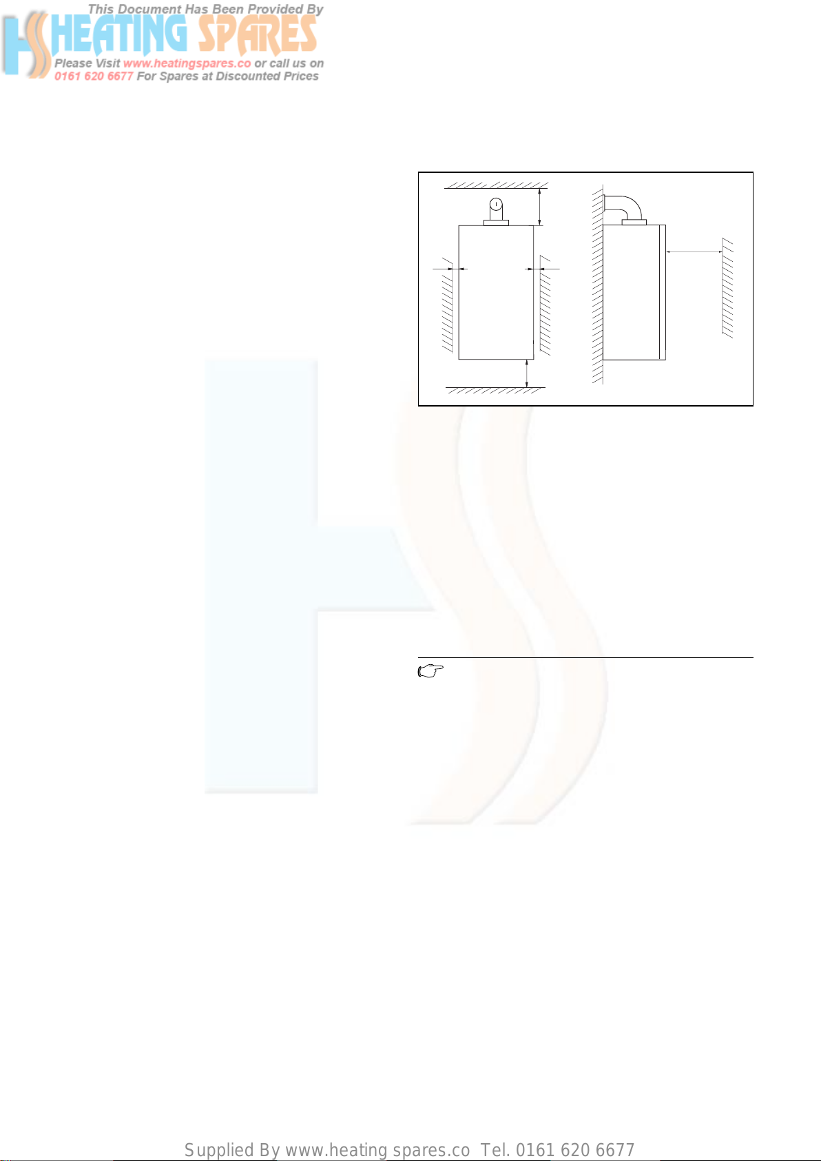
4.2 Required minimum distances/assembly clearances
min
165/246*
min 5
Fig. 4.1 Distances during installation (dimensions in mm)
min 5
min 180
min 500**
The boiler should be mounted on a flat and vertical area
of wall of sufficient area for the boiler plus the required
clearances for installation and servicing (fig. 4.1). These
are shown on the installation template supplied with the
boiler and are:
– 5 mm either side of the boiler
– 180 mm below the boiler
– 165 mm* above the boiler when utilising the 100 mm
outside diameter flue
– 246 mm* above the boiler when utilising the 125 mm
outside diameter flue
– 500 mm in front of the boiler to enable easy access
for servicing (may be provided by an opening door)
Note
If the boiler is to be fitted in a timber framed
building, it should be fitted in accordance with
British Gas publication DM2 ‘Guide for gas
installations in timber framed housing’.
4.2.1 Select position for boiler
Refer to section 3.4 ‘Installation site’ for information
regarding the appliance location. In general the boiler
must be positioned such that:
• There is adequate space around the boiler for service
and maintenance
• The boiler can be correctly flued, i.e. the flue terminal
position is located in accordance with these instructions and the air/flue duct can be installed in accordance with the flue installation instructions supplied.
• All necessary pipework can be connected, including
the pressure relief valve and condensate drain.
4.2.2 Unpack the boiler
To unpack the boiler, cut both plastic carton straps, open
box and lift out the polystyrene top packing. Lift the
cardboard box upwards.
18 Instructions for installation and servicing ecoTEC
Page 19
Supplied By www.heating spares.co Tel. 0161 620 6677
Note
Care should be taken not to scratch the white
surface of the boiler casing.
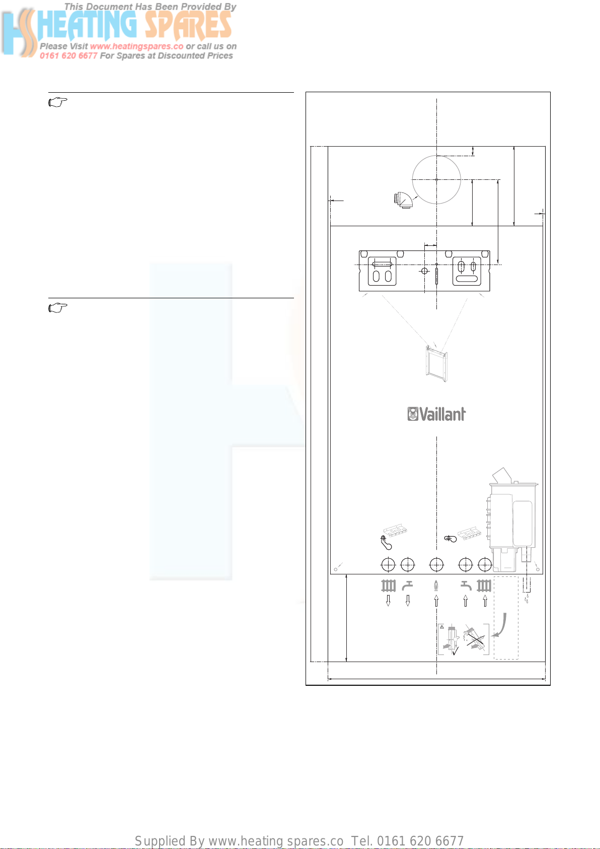
4.2.3 Using boiler template
• Fix the paper template to the wall ensure that the
template is vertical.
The template shows:
– The position of the fixing holes for the boiler mounting
bracket.
– The position of the connections.
– The position of the flue exit hole.
• Mark the position of the hanging bracket fixing holes.
• Drill 2 holes Ø 10 mm for the hanging bracket.
Note
Use alternative fixing holes where necessary.
Boiler installation sequence 4
20
165
5
60/100
25
A
95
175
A
5
A
1065
A
180
A
Fig. 4.2 Assembly template
45°
256723_01 01 2005
450
19Instructions for installation and servicing ecoTEC
Page 20
Supplied By www.heating spares.co Tel. 0161 620 6677
4 Boiler installation sequence
4.3 Flue exit
• If using rear flue mark the position of the air/flue duct
and its circumference.
Other flue options
Flue instructions for other flue systems such as vertical
RSF flues, flues run to the side of the boiler and the use
of additional bends etc. are detailed in the flue installation instructions provided with the boiler.
• Remove the template from the wall and plug the
drilled holes using the wallplugs supplied.
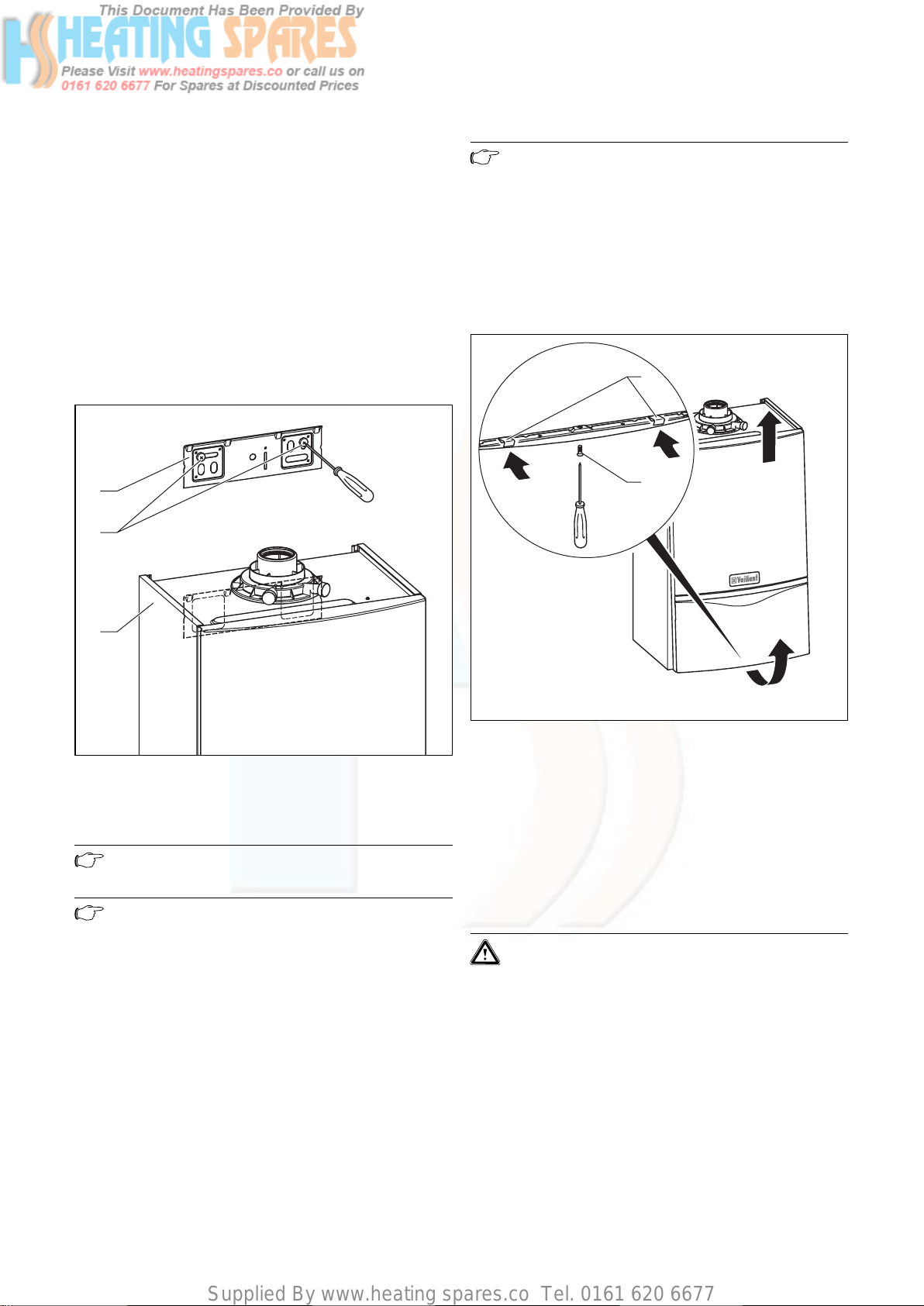
4.4 Fitting the boiler hanging bracket
1
2
Note
Lift the boiler from either side at the bottom
edge
• Lower the boiler slowly onto the hanging bracket so
that the cross member at the rear of the boiler fully
engages onto the hanging bracket.
4.7 Removing the front case
2
1
3
Fig. 4.3 Appliance with hanging bracket
• Fix the hanging bracket to the wall using the plugs and
screws provided with the appliance.
Note
Use alternative fixing holes where necessary.
Note
If the boiler is to be fitted in a timber framed
building ensure that the bracket is secured to a
substantial part of the timber frame capable of
taking the weight of the boiler.
4.5 Installing the flue system
• Install the flue system (refer to the seperate air/flue
duct installation instructions).
Fig. 4.4 Removing/fixing the front case
To remove the front section of the case, proceed as follows:
• Loosen the screw (1) on the bottom of the unit.
• Push in the two retaining clips (2) on the bottom of
the appliance until the case is released.
• Grasp the front case by its bottom edge, pull it towards
the front and remove it by lifting it off the unit.
4.8 General instructions for heating system
Caution!
Thoroughly cleanse the heating system before
connecting the appliance!
By doing that, residue such as welds, cinder,
hemp, putty, rust, rough dust and similar substances are removed from the pipes. Otherwise
such substances can be deposited in the appliance and cause damage.
4.6 Fitting the boiler
• Lift the boiler (3) up to the wall so that it is slightly
above the hanging bracket (1).
- The appliance is fitted with an expansion vessel (10
l/0.75 bar). Before assembling the appliance check if
this volume is adequate. If not, an extra expansion vessel must be installed, see section 3.10.5.
20 Instructions for installation and servicing ecoTEC
Page 21
Supplied By www.heating spares.co Tel. 0161 620 6677
Boiler installation sequence 4
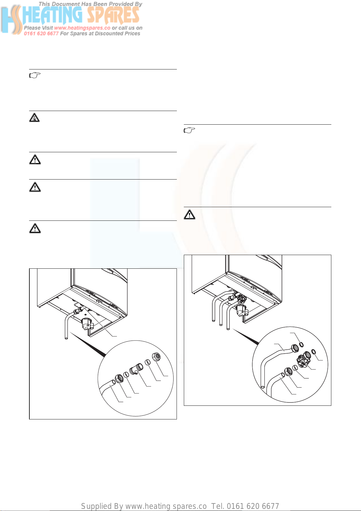
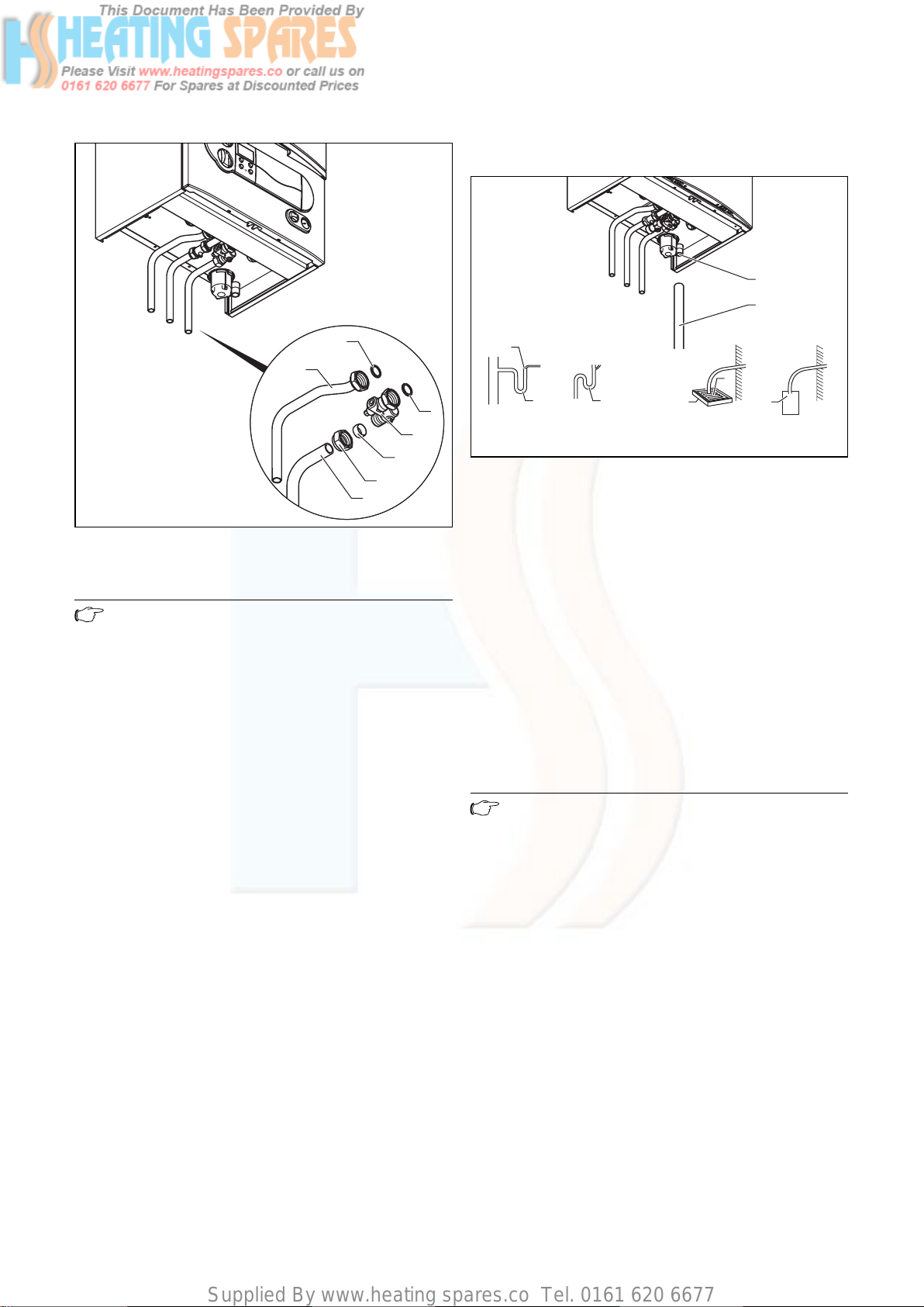
4.9 Gas connection
Note
With the spacer frame (Art. No 308 650), the
pipes can be fitted vertically upwards behind
the appliance. The distance of the appliance
from the wall thus increases by 65 mm.
Danger!
The gas connection may only be made by a
competent person.
The legal directives and the local regulations
for gas supply companies must be observed.
Caution!
Ensure a stress-relief assembly of the gas pipes
to avoid leakages!
Caution!
The gas regulating block may be tested for leakage only with a maximum pressure of 150 mbar!
Higher testing pressures can damage the gas
fitting.
Caution!
When making final connection to the boiler, if
using soldered fittings, extra care should be
taken to avoid damage to isolation valves
through heat transfer.
• Fit the union nut (6) and the compression olive (5) to
the pre-formed tail provided with ecoTEC plus appliances (7).
• Fully insert the service valve (4) onto the gas connection pipe and the pre-formed tail into the service valve.
Tighten both union nuts of the service valve.
• The diameter of the pipework (7) is 15 mm (22 mm for
37kW models). Connect a gas supply pipe of not less
than 15 mm diameter to the copper tail.
Note
Ensure the gas supply pipework is adequately
sized so that a 20 mbar gas pressure is available at the boiler inlet at full flow rate.
• Tighten all connections.
• Check the gas connection with leak indicator spray for
leakage.
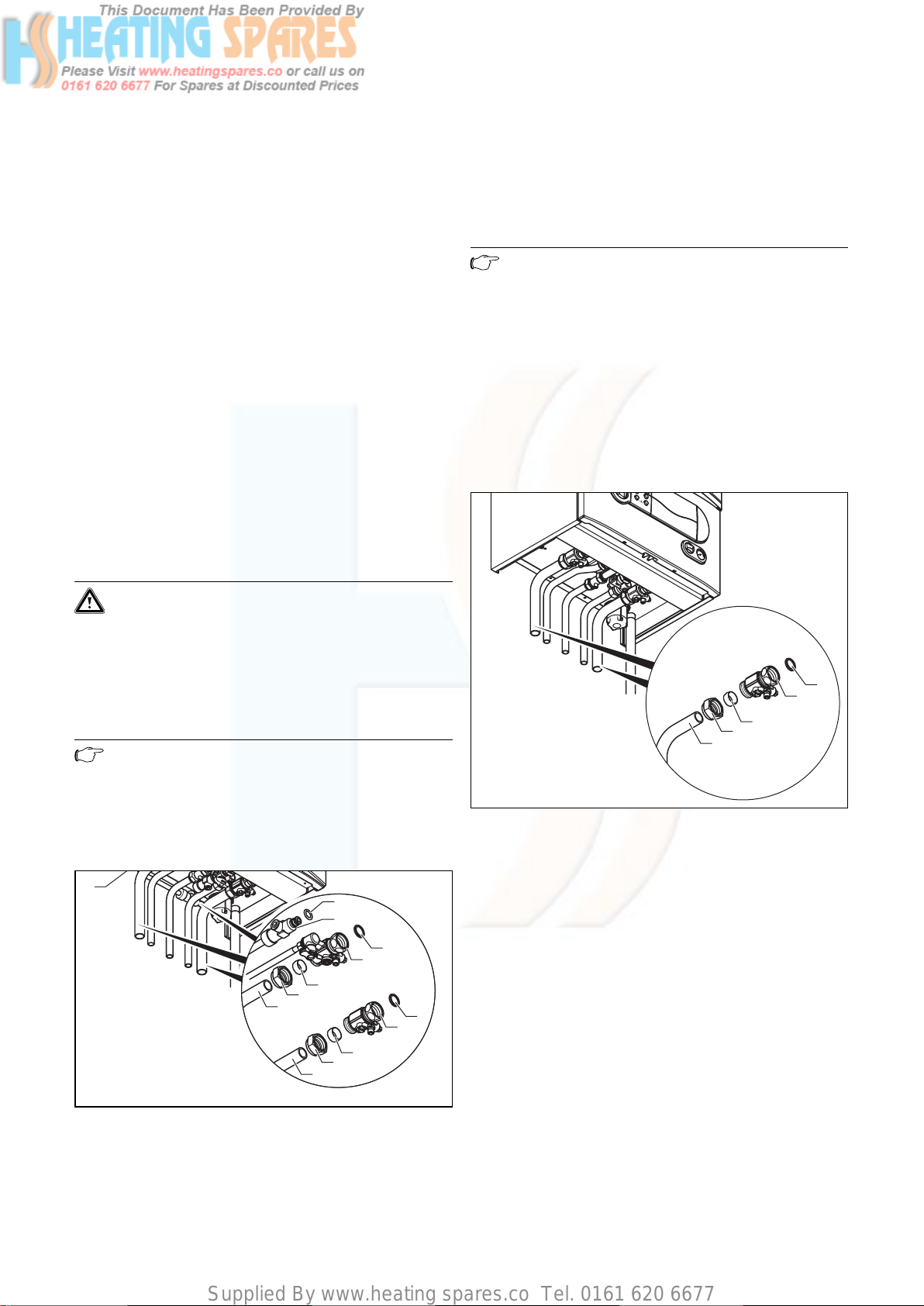
4.10 Cold water mains inlet and hot water outlet
(ecoTEC combination boilers only)
Caution!
When making final connection to the boiler, if
using soldered fittings, extra care should be
taken to avoid damage to isolation valves
through heat transfer.
1
2
3
4
5
6
7
Fig. 4.6 Installing the hot and cold water connection (ecoTEC
Fig. 4.5 Fitting the gas connection (example ecoTEC plus com-
bination boiler)
• Fit the union nut (2) and the compression olive (3) to
the gas connection pipe (1) of the boiler.
7
6
1
2
3
4
5
plus combination boiler)
21Instructions for installation and servicing ecoTEC
Page 22
Supplied By www.heating spares.co Tel. 0161 620 6677
4 Boiler installation sequence
bar
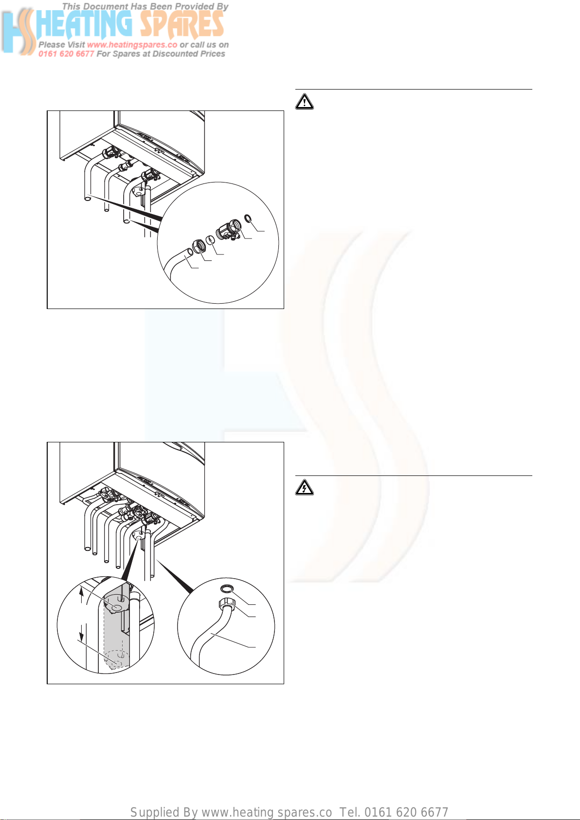
4.11 Condensate drain pipe
1
2
7
6
1
2
3
4
5
Fig. 4.7 Installing the hot and cold water connection (ecoTEC
pro combination boiler)
Note
Flush all foreign matter from the mains supply
before connecting to the boiler.
• Insert the seal (1) and connect the service valve (2) to
the appliance cold water connection.
• Fit the union nut (4) and the compression olive (3) to
the pre-formed tail provided with ecoTEC plus appliances (5). The diameter of the pipe is 15 mm.
• Fully insert the pre-formed tail into the service valve.
Tighten the union nuts.
• Insert the seal (7) and connect in the pipe (6) to the
appliance hot water connection. The diameter of the
pipe is 15 mm.
• Mount the handle for the filling loop with a countersunk screw to the service valve (2).
4
a
3
Internal
stackpipe
Fig. 4.8 Installing the condensate drain pipe (picture shows
ecoTEC plus combination boiler)
b
3
Internal
discharge system
5
c
Gulley
d
6
7
Soakaway
The ecoTEC plus appliances are fitted with a siphonic
trap (The filling height is 145 mm). The siphon collects
the accumulated condensate in a container of approx.
200 ml capacity and directs the entire content into the
drain pipe. The risk of the condensate drain pipe freezing is thus minimised.
The ecoTEC pro appliances are equipped with a normal
condensing water trap where the condensate is constantly emptied into the drain pipe.
• Connect the boiler condensate drain (1) to a condensate discharge pipe (2) which should be minimum of
19 mm internal diameter (22 mm external diameter for
any pipework installed external to the property) and
be made of an acid resistant material (e.g. plastic overflow pipe).
Note
The discharge pipe from the boiler condensate
drain must have a continuous fall (45 mm per
meter) and preferably be installed and terminated within the building to prevent possible freezing.
The condensate discharge pipe must terminate in a suitable position, e.g.:
a) preferably the discharge pipe should run and termi-
nate internally to the house soil and vent stack (at
least 450 mm above the invert of the stack). A trap
giving a water seal of at least 75 mm (3) (built into the
boiler) should be incorporated into the pipe run, and
there must be an air break (4) in the discharge pipe
upstream of the trap. The connection to the stack
should not be made in a way that could cause cross
flow into any other branch pipe, or from that branch
pipe into the condensate drainpipe. This can be
achieved by maintaining an offset between branch
pipes of at least 110 mm on a 100 mm diameter stack
and 250 mm on a 150 mm diameter stack.
22 Instructions for installation and servicing ecoTEC
Page 23
Supplied By www.heating spares.co Tel. 0161 620 6677
Boiler installation sequence 4
b) connecting into the internal discharge branch (e.g. sink
waste or washing machine) with an external termination, the condensate discharge pipe should have a
minimum diameter of 22 mm with no length restriction
and should incorporate a trap with a 75 mm (3) (built
into the boiler) seal. The connection should preferably
be made down stream of the sink waste trap. If the
connection is only possible upstream, then an air
break is needed between the two traps. This is normally provided by the sink waste.
c) terminating in a gully (5) below grid level (6) and
above the water level. The external pipe length should
be kept as short as possible to minimise the risk of
freezing and should not be more than 3 m.
d)at a condensate absorption point (soakaway) (7). The
external pipe length should not be more than 3 m.
Refer to ‘BS 6798 Specification for installation of gas–
fired boilers of rated input not exceeding 70 kW net’ for
further information. Before operating the boiler the condensate trap (1) must be filled with water as described in
relevant section.
4.12 Heating connection
Caution!
When making final connection to the boiler, if
using soldered fittings, extra care should be
taken to avoid damage to isolation valves
through heat transfer.
4.12.1 Heating flow and return connection
Note
Before connecting the heating circuit to the
boiler, all pipework and radiators must be thoroughly flushed to remove any installation
debris.
ecoTEC plus combination boiler
13
6
12
11
10
9
8
7
1
2
3
4
5
• Insert the seal (1) and fit the service valve (2) to the
return connection of the appliance.
• Insert the seal (10) and fit the service valve (9) to the
flow connection of the appliance.
• Install the O-ring seal (12) on the return valve (11).
Note
Lay the filling loop hose (13) above the pipework
elbows.
• Fit the union nuts (4) and (7) as well as the compression olives (3) and (8) to the pre-bended 22 mm copper tails (5) and (6).
• Fully insert pipes (5) and (6) into the service valves.
Tighten the union nuts in this position.
• Fit the handle for the filling loop with a countersunk
screw to the service valve (9).
ecoTEC pro combination boiler
bar
1
2
3
4
5
Fig. 4.10 Heating flow and return connection for ecoTEC pro
combination boiler
• Insert a seal (1) and fit the service valves (2) to the
flow and return connection of the appliance.
• Fit a union nut (4) and a compression olive (3) to the
22 mm pre-bended copper tail (5) .
• Fully insert pipe (5) into the service valve. Tighten the
union nuts in this position.
Fig. 4.9 Installing the heating flow and return connection for
ecoTEC plus combination boiler
23Instructions for installation and servicing ecoTEC
Page 24
Supplied By www.heating spares.co Tel. 0161 620 6677
4 Boiler installation sequence
ecoTEC plus system boiler
1
2
3
4
5
Fig. 4.11 Heating-side flow and return connection for ecoTEC
plus system boiler
• Insert a seal (1) and fit the service valves (2) to the
flow and return connection of the appliance.
• Fit a union nut (4) and a compression olive (3) to the
22 mm pre-bended copper tail (5) .
• Fully insert pipe (5) into the service valve. Tighten the
union nuts in this position.
4.12.2 Pressure Relief Valve
Caution!
To ensure fumes do not escape through the
syphon of the boiler the trap must be filled with
water before the boiler is turned on. Therefore
the discharge pipework should be installed so as
not to interfere with the removal and refitting
of the condensate trap, we recommend the outlet pressure release valve pipe supplied is not
shortened.
You must leave a bottom clearance of at least
180 mm below the condensate trap for removal
and refitting.
The pressure release valve for the heating system is
integrated in the appliance.
• Position the seal (1) and screw the drain pipe (2) on to
the pressure release valve.
The discharge pipework should be as short as possible
and installed with a continuous fall away from the boiler.
The pipe should terminate in a position which ensures
that any discharge of water or steam from the valve cannot create a hazard to persons in or around the premises, or cause damage to any electrical components or
external wiring, and the point of discharge should be
clearly visible.
4.13 Connecting the flue system to the boiler
• Refer to separate air/flue duct installation instructions
included with the boiler.
4.14 Electrical connection
min.
180
Fig. 4.12 Installing the drain pipe on the pressure release valve
of the heating system (picture shows ecoTEC plus
combination boiler)
1
2
3
4.14.1 General requirements
Danger!
Electrocution caused by touching live parts can
be fatal.
Before working on the appliance, turn off the
power supply and secure against restart.
All electrical work shall be carried out by a competent
person and shall comply with BS 7671 (IEE Regulations).
In the Republic of Ireland, reference should be made to
the current edition of the ETCI (Electro-Technical Council
for Ireland) rules. The boiler is supplied for connection
to 230 V, ~ 50 Hz supply fused at 3 A rating. Connection
to the mains supply shall be made via a fused 3 pin plug
to an unswitched shuttered socket, both complying with
the requirements of BS 1363.
(Alternatively, connection may be made via a 3 A fused
double pole isolator having a contact separation of at
least 3 mm in all poles and supplying the boiler and controls only). The point of connection to the mains supply
must allow complete electrical isolation of the boiler and
its ancillary controls. It should be readily accessible and
adjacent to the boiler. A 3 core flexible cord according to
BS 6500 tables 6, 8 or 16 (3 x 0.75 to 3 x 1.5 mm
2
)
should be used.
24 Instructions for installation and servicing ecoTEC
Page 25
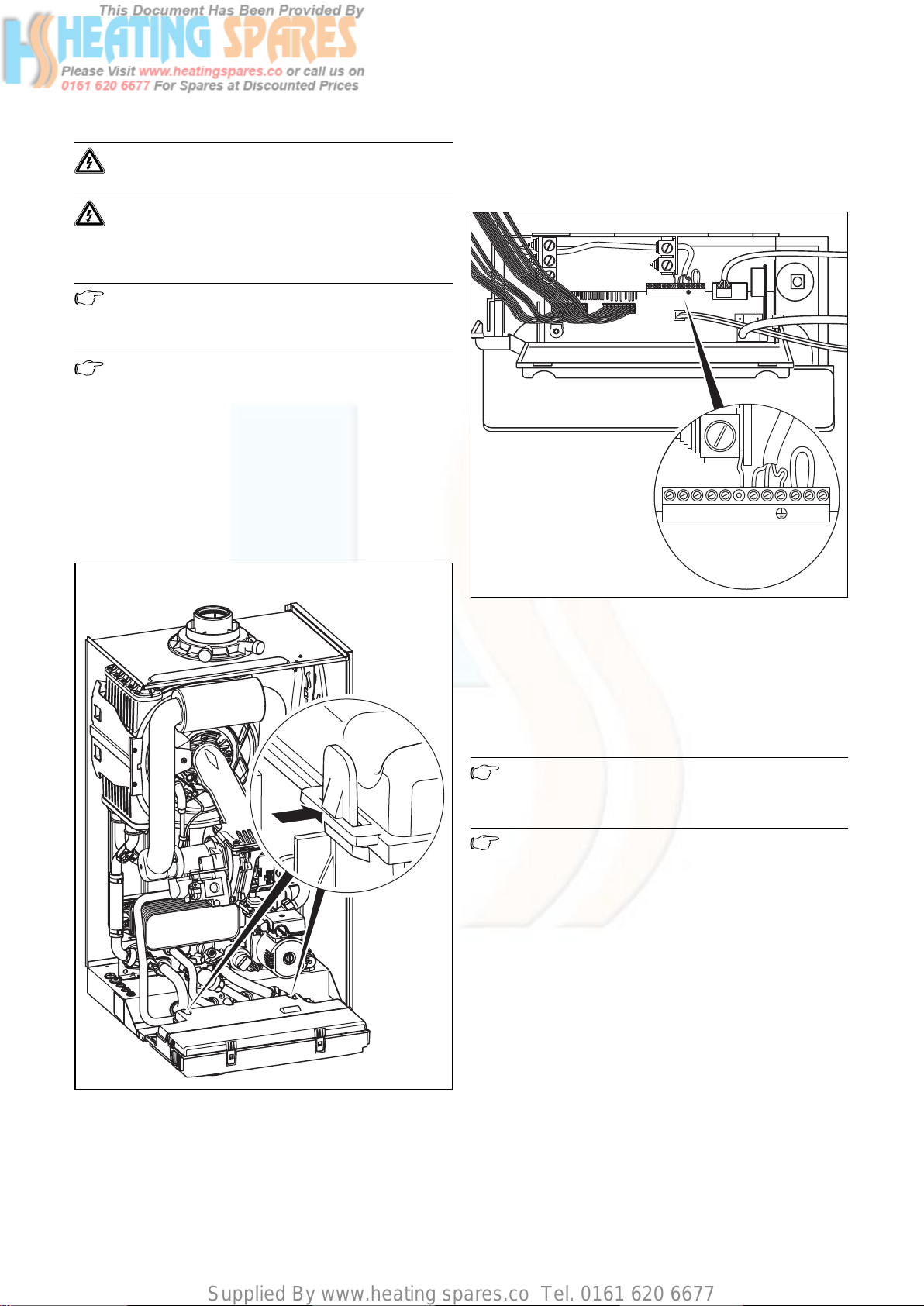
Supplied By www.heating spares.co Tel. 0161 620 6677
-+789 LN 345
Boiler installation sequence 4
Danger!
This appliance must be earthed.
Danger!
Mains connection terminals L and N remain live
even when the boiler on/off control is switched
off.
Note
Do not connect any power voltage to the connections 7-8-9 or BUS (+,-).
Note
Ensure that all cords pass through the cable
clamps in the rear of the control box and are
securely fixed. Ensure that the power supply is
connected such that the current carrying conductors become taut before the earth conductor
should the supply cord slip from the cable clamp.
4.14.2 Connection to the main supply
• Remove the front case and lower the control panel.
• Feed the power supply flex into the appliance and the
control panel through the cable clamps provided and
tighten.
-+789 LN 345
Fig. 4.14 Wiring system
• Connect the flex to the L, N and earth plug to the terminal block.
Green/yellow (earth) wire – boiler terminal Earth sign
Blue (neutral) wire – boiler terminal N
Brown (live) wire – boiler terminal L
Note
Do not connect any power voltage to the connections 7-8-9 or BUS (+,-).
Note
Ensure that the wires are securely fixed in the
terminal block.
• Refit the terminal box cover by pushing into place until
it clips back into position.
• Raise the control panel.
Fig. 4.13 Opening the electronics box
• Unclip the bottom of the terminal box cover and hinge
back to reveal the connection plugs.
25Instructions for installation and servicing ecoTEC
Page 26
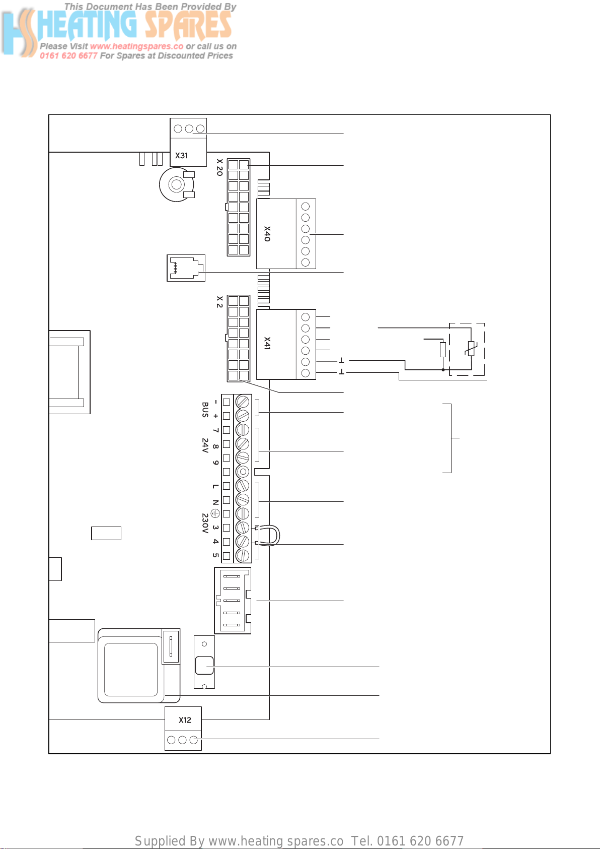
Supplied By www.heating spares.co Tel. 0161 620 6677
4 Boiler installation sequence
4.14.3 Electric board layout
eBUS accessory connection
Burner cable harness
Accessory module connection
Diagnosis via eBUS,
vrnetDIALOG
outer probe
ext. flow or return probe
Hydraulic cable harness
Connection for external
eBUS controller
Room thermostat 24 V:
Connection 7, 8 and 9
No bi-directional
interface (analogue only)
Mains supply: 230 V/50 Hz
Room thermostat 230 V/50 Hz
(remove bridge on connection)
Heating pump
With ecoTEC pro: 1-step pump (plug with 3-pin)
With ecoTEC plus: 2-step pump (plug with 5-pin)
2A fuse, slow
Caution:
Do not connect
supply voltage!
Risk of damage
to electronics!
Fig. 4.15 Connection wiring ecoTEC
26 Instructions for installation and servicing ecoTEC
Igniter
Connection: 230 V
Supply for accessory module
Page 27
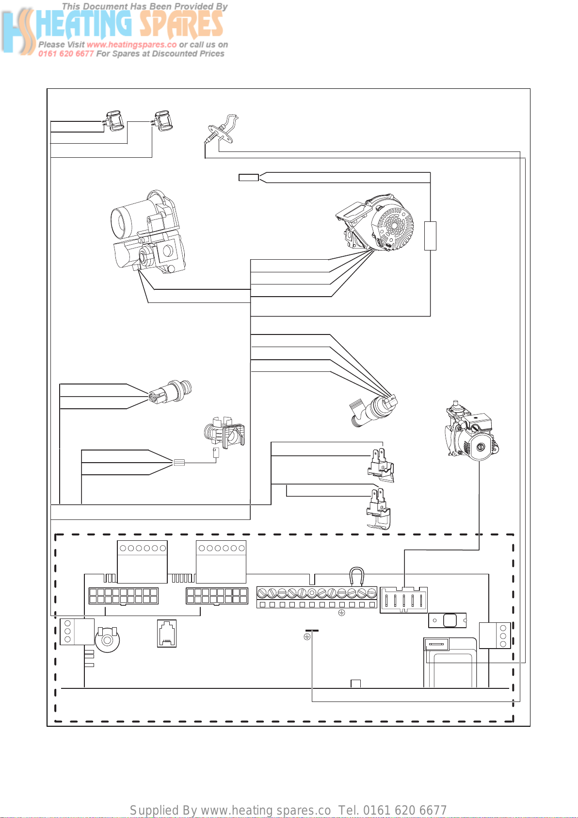
Supplied By www.heating spares.co Tel. 0161 620 6677
Boiler installation sequence 4
NTC
flow
X 20/5 red
X 20/7 black
X 20/8 blue
X 20/7 black
Gas valve assembly
X 2/9 black
X 2/11 red
X 2/12 green
NTC
return
Ignition electrode
Thermal fuse
X 20/18 red (24 VDC)
X 20/9 blue (earth)
Water pressure sensor
Aqua sensor
X 20/13 black
X 20/12 black
Fan unit
Plug
in
coupling
X 20/16 blue (earth)
X 20/4 grey (PWM)
X 20/3 black (Hall signal)
X 20/17 red (24 VDC)
X 2/16 black A
X 2/7 pink B
X 2/15 brown C
X 2/8 blue D
Diverter valve
Pump
X 2/3 red (+ 5V)
X 2/2 black (earth)
X 2/6 green (signal)
X40
X 20
X31
Electronic control box
X 2
X41
— +
BUS
X 2/4 orange
X 2/10 black
X 2/5 violet (signal)
X 2/1 black
7 8 9
24V
L N 3 4 5
230V
NTC
Plate heat
exchanger
ecoTEC plus only:
NTC
Hot water
outlet
X12
Fig. 4.16 Connection wiring ecoTEC combination boiler
27Instructions for installation and servicing ecoTEC
Page 28
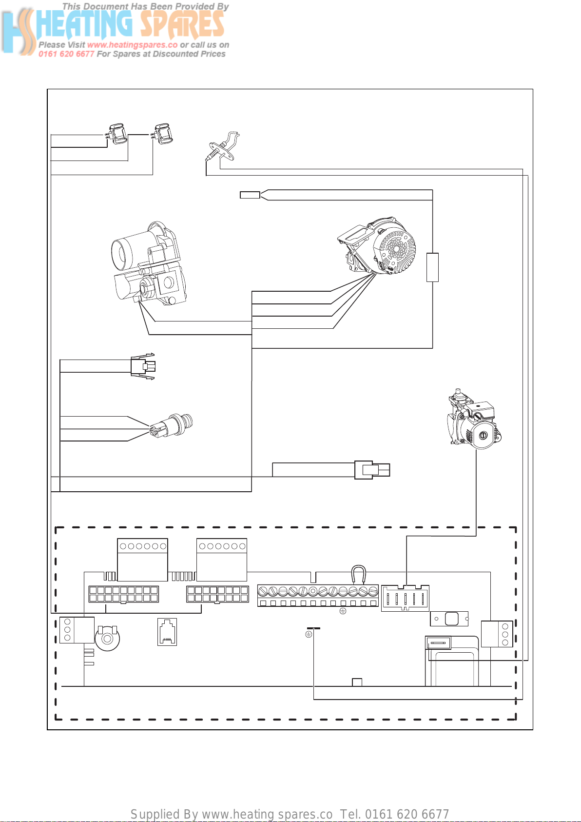
Supplied By www.heating spares.co Tel. 0161 620 6677
4 Boiler installation sequence
NTC
flow
X 20/5 red
X 20/7 black
X 20/8 blue
X 20/7 black
Gas valve assembly
X 2/10 black
X 2/14 brown
NTC
return
Hot water
contact C1/C2
Ignition electrode
Thermal fuse
X 20/18 red (24 VDC)
X 20/9 blue (earth)
X 20/13 black
X 20/12 black
Fan unit
Plug
in
coupling
X 20/16 blue (earth)
X 20/4 grey (PWM)
X 20/3 black (Hall signal)
X 20/17 red (24 VDC)
X 2/9 black
X 2/11 red
X 2/12 green
X 20
X31
Water pressure sensor
X40
X 2
X41
7 8 9— +
BUS 24V
X 2/4 orange
X 2/10 black
L N 3 4 5
Pump
tank NTC
connection
230V
X12
Electronic control box
Fig. 4.17 Connection wiring ecoTEC system boiler
28 Instructions for installation and servicing ecoTEC
Page 29
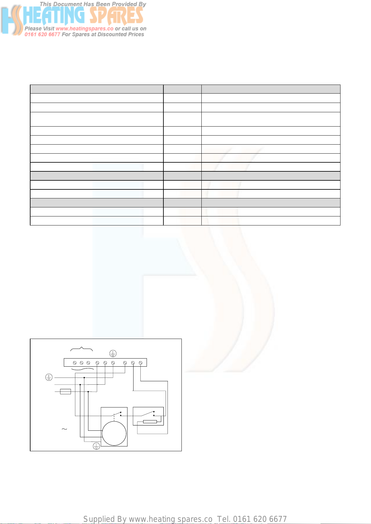
Supplied By www.heating spares.co Tel. 0161 620 6677
Boiler installation sequence 4
4.15 Controls
4.15.1 Vaillant controls and accessories
Controller Item no. Connection
VRC 400 (1-circuit controller, weather-controlled) 00 2001 0843 Installation in electronics box (plug-and-play)
VRT 360 (room temperature controller) 00 2001 0842 Wall-mounted, 2-wire bus
Available from 10-01-2006
VRT 360f (room temperature controller) 00 2001 8258 Wireless controller, receiver wall-mounted
VRT 230 (room temperature controller) 00 2001 0841 Wall-mounted, 3-wire connection to terminals 3-4-5
timeSWITCH 140 (timer) 306 760 Installation in electronics box (plug-and-play)
timeSWITCH 130 (timer) 306 759 Installation in electronics box (plug-and-play)
VRT 30 (room thermostat) 300 637 Wall-mounted, 3-wire connection to terminals 3-4-5
VRT 50 (room thermostat) 00 2001 8265 Wall-mounted, 2-wire bus
Telecommunication Item no. Connection
vrnetDIALOG 830 (Int) 00 2000 3988 GSM/GPRS, installation in electronics box (plug-and-play)
vrnetDIALOG 860/2 (Int) 00 2000 3984 Wall-mounted, GSM/GPRS, up to 16 appliances
Accessories Item no. Connection
VR 65 control centre for UK cylinder installation (eBUS) 307 215 System solution for UK cylinder connection
vrDIALOG 810/2 00 2002 3370 Diagnostic software
Table 4.1 Vaillant controls and accessories
4.15.2 External electrical controls
The boiler terminals 3, 4 and 5 are for connecting external electrical controls such as a time switch and/or room
thermostat. Terminals 3 and 4 are linked together when
the boiler is supplied. If external controls are used, this
link must be removed, and the controls connected
across terminals 3 and 4. Terminal 5 is an additional
neutral connection for external neutrals such as from
the anticipator of a room thermostat.
4.15.3 Connection details for external time switches
and boiler terminal strip
20 VDC (DO NOT USE 7, 8, 9 IN UK!)
987
LN
N
L
3 A FUSE
MAINS
SUPPLY
230 V
50 Hz
Fig. 4.18 Connection details for time switches
SWITCH
CONTACTS
L
CLOCK
N
5
4
3
ROOM
THERMOSTAT
N
If a room thermostat is to be connected in addition to a
time switch the wire between the time switch “ON” terminal and boiler terminal 4 should be broken by the contacts of the room thermostat (see schematic layout, fig.
4.18).
4.15.4 Vaillant optional plug in timer accessories
Refer to the instructions supplied with the optional
accessories for connection details. Upon completion of
all electrical connections refit the terminal box cover by
pushing into place. The cover is secured by two locking
clips.
4.15.5 Connection details using the VR 65 Control
Center
The Control Center VR 65 is an eBUS system component.
In a storage unit installation, it is responsible for the
communication between the storage unit, the ecoTEC
plus system boilers and external 2- or 3-way-valves.
Connect the VR 65 Controll Center as described in the
enclosed manual.
4.16 Thermostatic radiator valves
The boiler has a built in automatic by-pass valve making
it ideal for use in systems with thermostatic radiator
valves (no separate system by-pass is required). For optimum fuel economy where TRV’s are used they must be
used in conjunction with a boiler control interlock. A programmable room thermostat or separate timer and
room thermostat will ensure complete boiler shut down
when the heating demand is satisfied. (The radiator in
29Instructions for installation and servicing ecoTEC
Page 30
Supplied By www.heating spares.co Tel. 0161 620 6677
4 Boiler installation sequence
5 Commissioning Part I
the room containing the room thermostat should not be
fitted with a TRV).
4.17 Frost protection
The boiler has an integral frost thermostat which is
designed for protection of the boiler. To protect remote
or exposed parts of the heating system or property additional frost protection measures must be taken such as
the installation of an external frost thermostat. This
frost thermostat should be connected across the boiler
terminals 3 and 4, in parallel with any external heating
controls.
Note
External frost protection cannot be used when
plug in timers are utilised.
4.18 Circulating pump
The boiler incorporates a built in circulating pump that is
fully prewired (no additional wiring is necessary). The
pump incorporates an automatic overrun period after
the boiler switches off.
4.19 Anticycling ‘economiser’ control
The boiler incorporates a built in anticycling control to
ensure that energy wasteful short cycling of the boiler
cannot occur. This control prevents the boiler from reigniting for a preset period after central heating operation (the hot water operation is unaffected by this control and hot water can be drawn at any time).
5 Commissioning Part I
5.1 Preliminary electrical checks
Check the electrical installation by carrying out short
circuit, earth continuity and resistance to earth tests and
a check for correct polarity.
5.2 Gas supply
The complete gas installation including the gas meter
must be inspected, checked for leaks and purged in
accordance with BS 6891. In IE the current edition of IS
813. The gas supply to the boiler can be purged by slack-
ening the gas service valve beneath the boiler. Ensure
that there is adequate ventilation, extinguish all naked
flames and do not smoke whilst purging. After purging,
the gas service valve connection must be retightened
and checked for leaks. (The boiler itself does not require
purging as this will be done by the automatic burner
sequence control).
5.3 Cold water supply (ecoTEC combination boilers
only)
Open all domestic hot water taps supplied by the boiler,
turn on the mains water supply to the boiler and open
the mains water isolating valve below the boiler. Water
will now flow through the boiler to the hot taps. Starting
with the lowest tap supplied, turn the hot taps off one at
a time until the hot water pipework is purged of air.
Check all hot and cold water pipework for leaks.
5.4 Filling and bleeding the heating system
Note
To temporarily override the anticycling control
turn the main boiler on/off switch to the off
position “0” and then back to the on position
“I” after a few seconds.
4.20 Automatic pump spin control (APS)
The boiler incorporates a built in control which will spin
the built in circulating pump and operate the diverter
valve (ecoTEC combination boilers only) once in a 23
hour period. This control helps to prevent seizure when
the boiler is not operated for a period of time. This control is not active when the power supply to the appliance
is turned off.
Note
The P.6 test program is for filling the heating
system: The diverter valve (combination boilers
only) moves to the centre position, the pump
does not run and the appliance does not go into
heating mode. Use the test program as
described in Section 8.4.
The P.0 test program is for bleeding the hot
water circuit (as well as the DHW circuit on
combination boilers): The appliance does not go
into heating mode; the pump runs inttermittently and bleeds the two circuits in succession.
Use the test program as described in Section
8.4.
30 Instructions for installation and servicing ecoTEC
Page 31

Supplied By www.heating spares.co Tel. 0161 620 6677
5.4.1 Checking the filling pressure of the heating
system
plus pro
iFP
Commissioning Part I 5
4
3
bar
2
1
bar
Fig. 5.1 Checking the filling pressure of the heating system
Note
The ecoTEC appliances come with a manometer
and a digital pressure indicator.
The manometer allows you to quickly check
whether the filling pressure is in target range or
not even when the appliance is turned off.
If the appliance is in operation, you can display
the exact pressure by pressing the “-” (2).
For the heating system to operate properly, the indicator
on the manometer (1) must be in the dark grey area
when the system is cold. This corresponds to a filling
pressure between 1.0 and 2.0 bar. If the pointer is in the
light grey area, please refill water.
If the heating system extends over several storeys, the
system may require a higher filling pressure.
1
2
Fig. 5.2 Filling device ecoTEC plus combination boiler
• Insert the double check valve (1) of the filling pipe at
the cold water shutoff valve and secure the double
check valve with the spring clip (2).
• To fill, first open the stop valve (3).
• Open the stop valve (4), so that water flows into the
heating system. Fill the heating system as described in
Section 5.4.4.
• Close both stop valves after filling and detach the filling device by pulling the double check valve from the
cold water stop valve.
Note
Both stop valves must be closed while operating the heating system and the filling pipe must
be again detached at the double check valve.
5.4.2 ecoTEC plus combination boiler filling loop
The ecoTEC plus combination boiler will be delivered
with a filling loop.
Fig. 5.3 Double check valve detached while heating
31Instructions for installation and servicing ecoTEC
Page 32
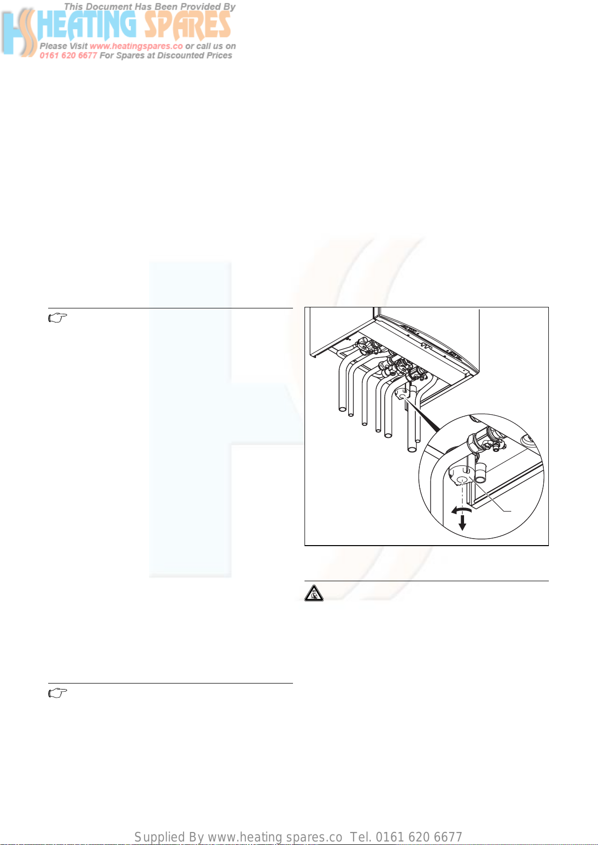
Supplied By www.heating spares.co Tel. 0161 620 6677
5 Commissioning Part I
5.4.3 Filling the heating system in ecoTEC pro combination boilers and ecoTEC plus system boilers
The ecoTEC pro combination boilers and the ecoTEC
plus system boilers do not come with a filling device. In
these appliances, water is filled in the heating system
through a filling pipe provided onsite.
• Join a hose between a cold water dispensing valve and
the filling pipe of the heating system.
• To fill, first open the cold water dispensing valve.
• Open the stop valve on the filling pipe, so that water
flows into the heating system. Fill the heating system
as described in Section 5.4.4.
• After filling, close the stop valve on the filling pipe and
the cold water dispensing valve and remove the filling
hose.
5.4.4 Filling the heating system for the first time
Note
As long as there is insufficient water pressure
in the heating system, the display indicator
changes between the error message F.22 and
the actual pressure indicator when the appliance is on.
• Connect a hose to the drain valve located at the lowest position of the heating system.
• Open the 1/2” BSP drain taps and all vent valves on
the heating elements and allow the water to flow out
of the heating system and the boiler quickly and completely to remove all installation residue from the
heating system before commissioning the boiler.
• Close the 1/2” BSP drain taps.
• Fill the heating system again with water as described
in Section 5.4.4.
• Check that the pressure relief valve of the heating system is working by turning the handle on the valve.
• Check the pressure in the heating system and fill
water if needed.
• Close the filling valve and the cold water dispensing
valve.
5.6 Filling the condensate siphon
Fill the heating system as follows:
• Open all heating element thermostat valves.
• Check if both stop valves on the heater are open.
• Only in ecoTEC plus combination boilers: Connect the
filling pipe as described in Section 5.4.2.
• Only in ecoTEC plus system boilers and in ecoTEC pro
combination boilers: As described in Section 5.4.3 join
a hose between the cold water dispensing valve and
the filling pipe of the heating system.
• Open the cold water dispensing valve.
• Slowly open the filling valve and let the water flow into
the heating system. Bleed the lowest radiator until the
water flows out at the bleed valve without bubbles.
• Bleed all other radiators until the heating system is
completely filled with water, all bleed valves have been
shut and the manometer pointer is in the centre of the
dark grey area. Bleed the heating pump by loosening
the central screw. Close the filling valve and the cold
water dispensing valve.
• Loosen the cap of the pump A.A.V. (automatic air vent)
(the appliance is ventilated independently by the pump
A.A.V. during continuous operation).
• Check all connections and the entire system for leaks.
5.5 Initial system flush (“cold”)
Note
The complete heating system must be flushed
out at least twice: once cold, and once hot as
instructed below.
1
Fig. 5.4 Filling the condensate siphon
Danger!
Note that if the boiler is run with an empty
condensate trap there is a danger that fumes
might escape into the room and cause poisoning. For this reason, it is important to ensure
that the trap is topped up each time the unit is
cleaned.
• Remove the lower part (1) of the condensate siphon by
turning the bayonet catch in anticlockwise direction.
• Fill the lower part with water until about 10 mm below
the upper edge.
• Refit the lower part of the condensate siphon.
• Check if all radiator thermostatic valves and both service valves on the boiler are open.
32 Instructions for installation and servicing ecoTEC
Page 33
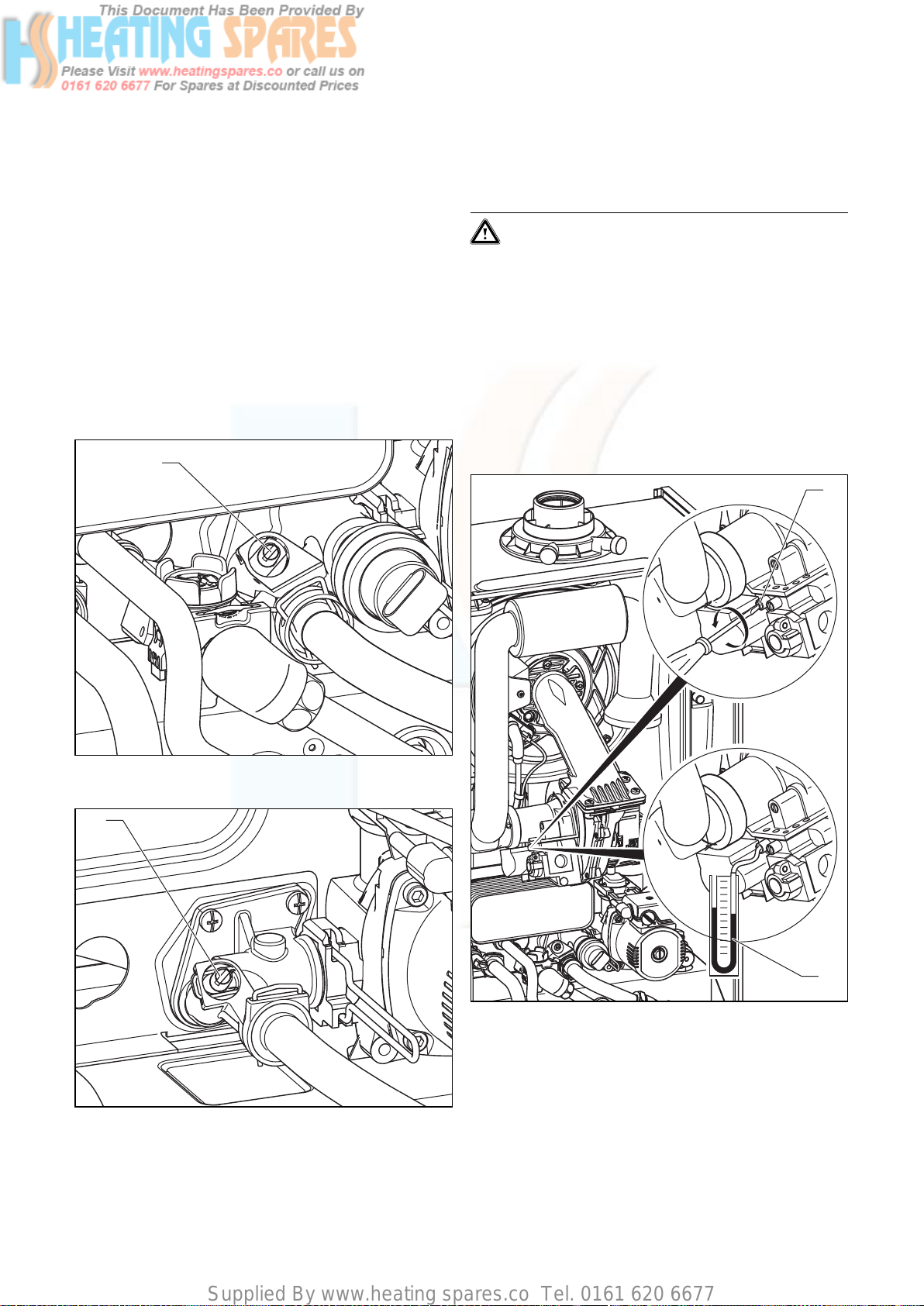
Supplied By www.heating spares.co Tel. 0161 620 6677
Commissioning Part I 5
5.7 Adjusting the pumping capacity
Only in ecoTEC plus boilers:
The capacity of the two-stage pump can be adjusted to
the requirements of the heating system. If needed,
change the setting of the operating mode dependent
pump speed under the diagnostic number “d.19” (see
section 8.1.2).
5.8 Adjusting the by-pass
The appliances have an adjustable by-pass valve.
The pressure can be adjusted between 170 and 350 mbar.
Approx. 250 mbar is preset (mid-position). The pressure
changes by approx. 10 mbar each time the adjusting
screw is rotated. By turning right, the pressure increases
and turning left decreases it.
1
5.9 Checking the gas supply
5.9.1 Factory settings
Caution!
Before operating the boiler check the data
badge and ensure that the correct gas type
appliance has been installed.
The boiler is supplied ready adjusted and no further gas
adjustments are necessary, however both the gas inlet
working pressures and maximum gas rates should be
checked as detailed in 5.9.2 and 5.9.3.
5.9.2 Gas inlet working pressure
Check the inlet pressure as described below:
• Remove the front case from the boiler.
• Close the gas shutoff valve fitted to the boiler.
1
Fig. 5.11 Adjusting the by-pass valve (in combination boilers)
1
Fig. 5.12 Adjusting the by-pass valve (in system boilers)
• Regulating the by-pass on the adjusting screw (1).
2
Fig. 5.13 Checking the gas supply pressure
• Loosen the sealing screw marked “in” (1) on the gas
valve assembly.
• Connect a digital or a U gauge (2).
• Open the gas shutoff valve fitted to the boiler.
• Put the boiler into operation (refer to the Instructions
for Use supplied with the boiler).
• Check the U gauge reading and ensure the inlet gas
pressure is between the pressures detailed below.
33Instructions for installation and servicing ecoTEC
Page 34
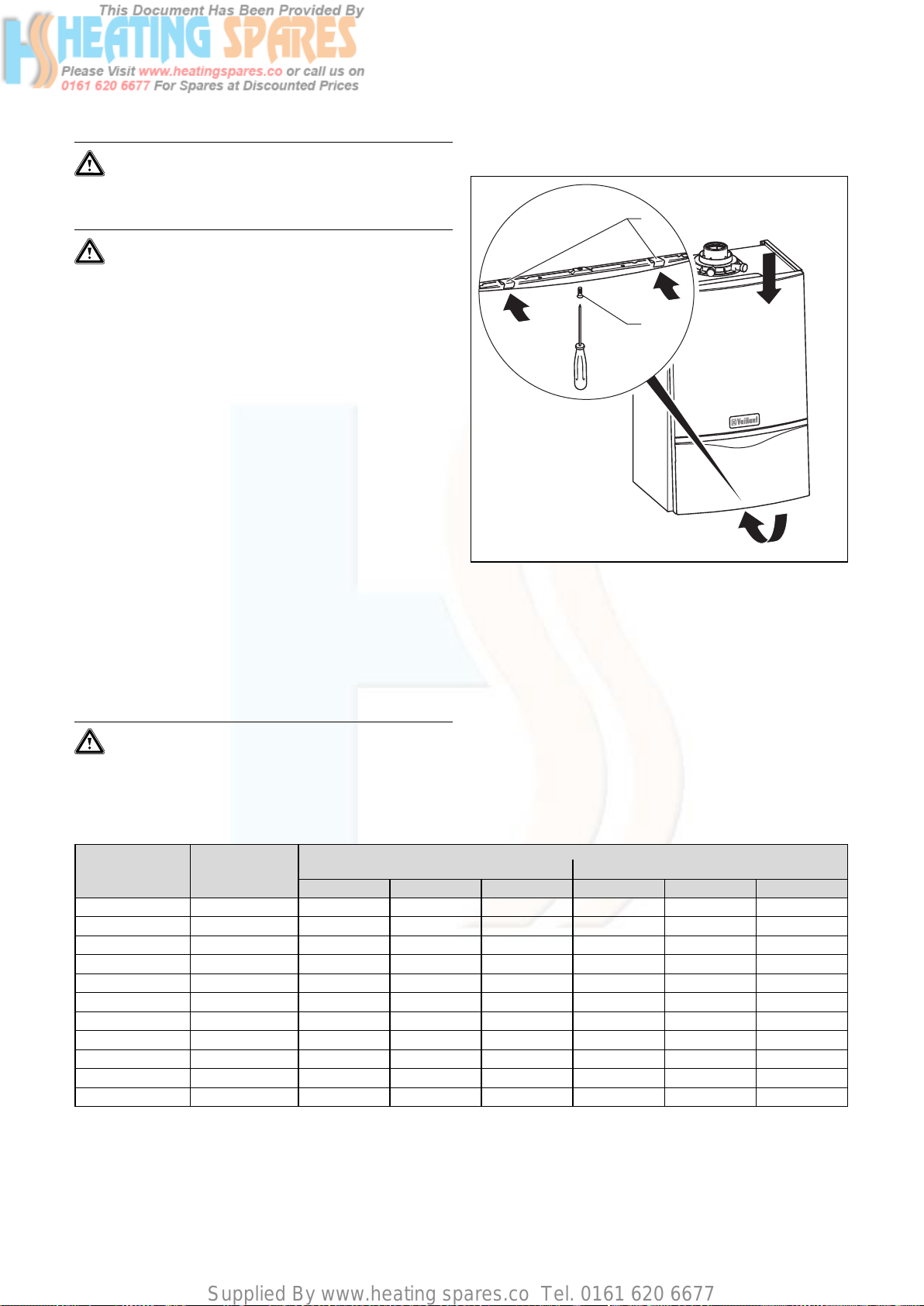
Supplied By www.heating spares.co Tel. 0161 620 6677
5 Commissioning Part I
Natural gas:
DO NOT proceed with adjustment or attempt to
put the unit into service if the inlet working
pressure lies outside the 17–25 mbar range.
LPG:
DO NOT proceed with adjustment or attempt to
put the unit into service if the inlet working
pressure is lower than 37 mbar.
• Turn off the appliance, remove U gauge.
• Tighten the test point screw and check for leaks.
• Record appliance working gas inlet pressure (mbar) in
the Benchmark gas boiler commissioning checklist.
5.9.3 Checking the gas rate
The boiler is fitted with a fully modulating automatic gas
valve which ensures that the precise air/gas ratio is provided under all operating conditions.
The gas rate has been set during production and does
not require adjustment.
The gas rate of the boiler should be checked with the
front case fitted as follows:
• Activate full gas rate mode by simultaneously pressing
the “+” and “–” buttons on the display system (for
ecoTEC combination boilers fully open the hot water
tap to maximum water flow rate).
• Wait at least 5 minutes, or until the boiler has reached
its operating temperature.
• With all other gas appliances turned off measure the
gas rate at the gas meter. Check that the gas rate is as
stated in Table 5.1.
5.10 Refitting the case
2
1
Fig. 5.14 Refitting the case
• Hook the top of the front casing over the lip on the
top of the boiler chassis and push the bottom of the
front casing into place.
• Ensure the spring retaining clips (2) engage correctly.
• Tighten case securing screw (1).
Caution!
If the measured gas flow volume lies outside
the tolerance limits specified in Table 5.1, do not
operate the appliance and inform the Vaillant
Customer Service.
Appliance
ecoTEC plus 612 12.2 1.29 1.36 1.16 0.95 1.00 0.85
ecoTEC plus 615 15.3 1.62 1.70 1.46 1.19 1.25 1.07
ecoTEC plus 618 18.4 1.95 2.04 1.75 1.43 1.50 1.29
ecoTEC plus 624 24.5 2.59 2.72 2.33 1.90 2.00 1.71
ecoTEC plus 630 30.6 3.24 3.40 2.91 2.38 2.50 2.14
ecoTEC plus 637 37.8 4.00 4.20 3.60 2.94 3.08 2.64
ecoTEC plus 824 23.5 2.49 2.61 2.24 1.83 1.92 1.64
ecoTEC plus 831 31.6 3.34 3.51 3.01 2.45 2.58 2.21
ecoTEC plus 837 37.8 4.00 4.20 3.60 2.94 3.08 2.64
ecoTEC pro 24 23.5 2.49 2.61 2.24 1.83 1.92 1.64
ecoTEC pro 28 28.6 3.03 3.18 2.72 2.22 2.33 2.00
Table 5.1 Gas rates
Maximum net
heat input in kW
nominal + 5% - 10% nominal + 5% - 10%
Natural gas in m
3
/h Propane in kg/h
Gas rate
34 Instructions for installation and servicing ecoTEC
Page 35
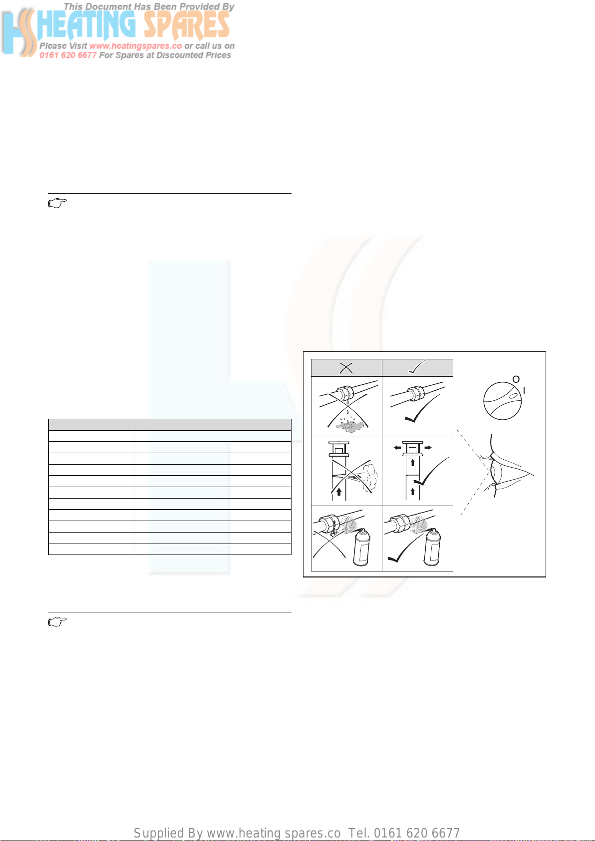
Supplied By www.heating spares.co Tel. 0161 620 6677
Commissioning Part I 5
Functional checks (commissioning part II) 6
5.11 Adjusting the central heating output (range
rating)
The boilers are fully modulating for central heating, and
it is therefore not necessary to range rate the boiler.
However, if desired, it is possible to range rate the boiler,
as follows:
• Press the “i” and “+” buttons simultaneously.
• Keep the “+” button pressed until “d.0” is displayed.
Note
The display runs from “d.0” to “d.99” before
restarting at “d.0”.
• Press the “i” button. The “=” symbol is displayed. The
part load setting is now displayed in kW.
• Use the “+” and “–” buttons to increase or decrease
the value in steps of 1 kW. The displayed value will
flash while the adjustment procedure is being carried
out. The available ranges of settings are given in Table
5.2.
• Push the “i” button for about five seconds, or until the
display stops flashing. The value is now saved to memory. The display will now return to its normal state
(current heating system flow temperature, e.g. 45 °C).
• Press the “i” and “+” buttons simultaneously to cancel
adjustment mode.
Adjustment mode is also cancelled if no button is
operated for a period of 4 minutes.
6 Functional checks (commissioning
part II)
6.1 Functional checks
6.1.1 Procedure
After installing and checking the gas supply pressure,
perform a function check before commissioning the
appliance and handing over to the user.
• Commission the appliance according to the relevant
operating manual.
• Check the gas supply pipe, exhaust system, heating
system and the hot water lines (combination boilers
only) for leaks.
• Check that the flue system has been installed properly
according to the flue system assembly manual.
• Check for ignition and an even flame on the burner.
• Perform a function check on the heating system (see
section 6.1.2) and the water heating (combination boilers only, see section 6.1.3).
• Hand over the appliance to the user (see section 6.2).
Appliance Heating output in kW
ecoTEC plus 612 5 – 12
ecoTEC plus 615 5 – 15
ecoTEC plus 618 7 – 18
ecoTEC plus 624 9 – 24
ecoTEC plus 630 10 – 30
ecoTEC plus 637 12 – 37
ecoTEC plus 824 7 – 19
ecoTEC plus 831 9 – 24
ecoTEC plus 837 12 – 28
ecoTEC pro 24 7 – 19
ecoTEC pro 28 9 – 24
Table 5.2 Heating system part load adjustment ranges
5.12 Gas changeover
Note
To reset the appliance from natural gas to LPG
mode, you need the Vaillant conversion kit Art.
No. 00 2001 0641.
To reset the appliance from LPG to natural gas
mode, you need the Vaillant conversion kit Art.
No. 00 2001 0642.
Convert the appliance as described in the conversion kit.
Fig. 6.1 Function check
35Instructions for installation and servicing ecoTEC
Page 36
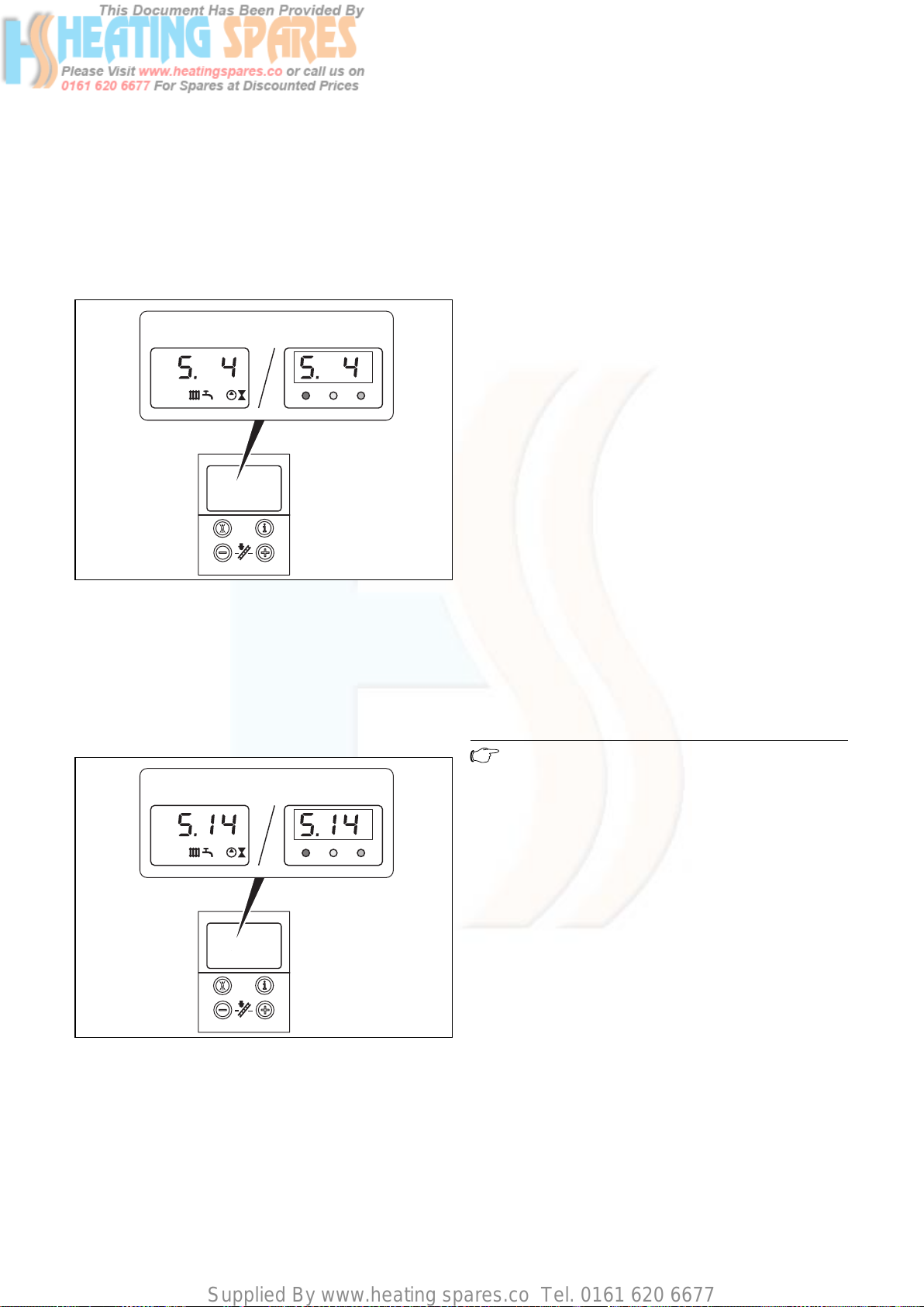
Supplied By www.heating spares.co Tel. 0161 620 6677
6 Functional checks (commissioning part II)
6.1.2 Heating
• Switch on the appliance.
• Make sure that there is a heating demand.
• Press “i” to activate the status indicator.
As soon as a heat demand is received, the appliance
runs through the status indicators “S. 1” to “S. 3”, until
the appliance is running correctly in normal mode and
the display shows “S. 4”.
plus pro
Fig. 6.2 Display indicator during heating mode
6.1.3 Water heating (combination boilers only)
• Switch on the appliance.
• Fully open the hot water tap.
• Press “i” to activate the status indicator.
If the water heating is working correctly, the display
shows the following: “S.14”.
plus pro
• Connect a hose to the drain valve located at the lowest position of the heating system.
• Shut off the appliance, open the drain valve and all
bleed valves on the radiators and allow the water to
flow out of the heating system and the boiler quickly
and fully.
• Close the drain valve.
• Fill the heating system again with water as described
in Section 5.4.4.
• Release water from the system until the system design
pressure of 1.0 bar is attained. (The actual reading on
the digital pressure gauge should ideally be 0.5 bar
plus an additional pressure corresponding to the highest point of the system above the base of the boiler –
10 m head equals an additional 1 bar reading on the
pressure gauge. The minimum pressure should not be
less than 1 bar in any installation.) If the system is to
be treated with an inhibitor it should be applied at this
stage in accordance with the manufacturer’s instructions. Further information can be obtained from
Sentinel, Betz Dearborn Ltd., Tel: 0151 420 9595, or
Fernox, Alpha–Fry technologies. Tel: 0870 8700362.
• Refit the boiler casing (see section 5.10).
• Only in ecoTEC plus appliances: Attach the bottom
cover to the boiler by sliding the front edge of the
cover into the lip at the bottom front edge of the
appliance chassis.
• Carefully push the rear of the bottom cover upwards
until the spring retaining clips engage at the side of
the appliance. It may be necessary to adapt the bottom cover by removing the easy break sections.
6.2 Handing over to the user
Note
When you have finished the installation, attach
the sticker supplied (835593) to the appliance
in the user’s language.
• Set the maximum radiator temperature control to the
desired setting.
• Set the maximum hot water temperature control to
the desired setting.
• Instruct the user in the safe and efficient operation of
the boiler, in particular the function of
– the boiler on/off control
– the maximum radiator temperature control
– the maximum hot water temperature control (combi-
nation boilers only)
– the pressure gauge
• Show the user how to operate any external controls.
Fig. 6.3 Display indicator during water heating
6.1.4 Final flush of the heating system (“hot”)
• Operate the appliance until the appliance and the
heating system are up to temperature.
• Check the heating system for leaks.
36 Instructions for installation and servicing ecoTEC
• Explain to the user the importance of having the boiler
regularly serviced by a competent servicing company.
To ensure regular servicing, it is strongly recommended that arrangements are made for a Maintenance
Agreement. Please contact Vaillant Service Solutions
(0870 6060 777) for further details.
• Record central heating operating pressure in the
Benchmark gas boiler commissioning checklist along
Page 37
Supplied By www.heating spares.co Tel. 0161 620 6677
Functional checks (commissioning part II) 6
Inspection and maintenance 7
with the heat input (kW) and temperature difference
between flow and return.
• Leave the user instructions and the installation
instructions with the user.
6.3 Vaillant warranty
Vaillant provide a full parts and labour warranty for this
appliance.
The appliance must be installed by a suitably competent
person in accordance with the Gas Safety (Installation
and Use) Regulations 1998, and the manufacturer’s
instructions. In the UK ‘CORGI’ registered installers
undertake the work in compliance with safe and satisfactory standards.
All unvented domestic hot water cylinders must be
installed by a competent person to the prevailing building regulations at the time of installation (G3).
Terms and conditions apply to the warranty, details of
which can be found on the warranty registration card
included with this appliance.
Failure to install and commission this appliance in compliance with the manufacturer’s instructions may invalidate the warranty (this does not affect the customer’s
statutory rights).
• Isolate the mains electricity supply by disconnecting
the plug at the socket outlet (if there is only an isolating switch remove the fuse from the switch).
• Turn OFF the gas supply at the gas service valve fitted
to the boiler.
• When removing any water carrying components
ensure that water is kept away from all electrical components.
• Always use new seals and O–rings when parts are
replaced.
• Always test for gas soundness and always carry out
functional checks after any service work and after
replacing any gas carrying component.
• Always check earth continuity, polarity and resistance
to earth with a multimeter after any service work and
after replacing any electrical component.
Danger!
Electrocution by touching live parts can be
fatal!
The supply terminals in the appliance switch
box are live even if the main ON/OFF switch is
turned off.
Protect the switch box from spray water.
Before working on the appliance, turn off the
power supply and secure against restart!
7 Inspection and maintenance
7.1 Initial inspection
To ensure the continued safe and efficient operation of
the boiler it is recommended that it is checked and serviced as necessary at regular intervals. The frequency of
servicing will depend upon the particular installation
conditions and usage. An inspection must be carried out
once a year.
Danger!
It is law that all servicing work is carried out by
a competent person (CORGI registered).
Inspections/Maintenance work not carried out
by a competent person can result in damage to
property and personal injury.
Only genuine Vaillant spare parts may be used for
inspections, maintenance and repair work to ensure the
long-term working order of all functions of your Vaillant
appliance.
Any spare parts which might be required are contained
in the current spare parts catalogues.
Information can be obtained from Vaillant Customer
Service Centres.
7.1.1 Safety instructions
Important:
Before starting any maintenance work:
Always perform the following steps after completing any
inspection tasks:
• Open the service valves in the heating flow and return
and in the cold water inlet (combination boilers only).
• If necessary, refill the device with cold water up to a
pressure of approx 1.5 bar and bleed air from the
entire heating system.
• Open the service valve of the gas supply pipe.
• Turn on the power supply and the main switch.
• Check the appliance for gas and water leaks.
• Fill and bleed air from the heating system again, if
necessary.
Note
If it is necessary to keep the main switch on for
certain inspection and maintenance, this is indicated in the description of the maintenance
task.
Note
The boiler is fitted with a combustion analysis
test point. A suitable combustion analyser can
be connected to this point to establish the combustion performance of the boiler. Checking/
adjustment of this value is required in the following instances; replacement of gas valve, conversion to or from Natural Gas/ LPG or if incorrect combustion is suspected (see section 9.7).
37Instructions for installation and servicing ecoTEC
Page 38
Supplied By www.heating spares.co Tel. 0161 620 6677
7 Inspection and maintenance
7.1.2 Maintenance
Before commencing any servicing or maintenance work,
carry out an initial inspection of the system as follows:
• Inspect the flue, pipework and electrical connections
for indications of damage or deterioration.
• Inspect the air supply and ventilation arrangements of
the installation.
• Check the heating and water system, in particular the
condition of radiator valves, evidence of leakage from
the heating system and dripping hot water taps.
7.1.3 Overview of the inspection and maintenance
tasks
Column 1
No. Activity
1 Check the air / gas flue system and ensure it is not blocked, damaged and is fitted correctly. x
Measure the gas rate during operation (see table 5.1 inside the chapter commissioning part I).
2
If the gas rate is lower than the minimum gas rate follow the maintenance instructions (column
2).
Check combustion by measuring CO and CO
is outside the tolerances follow the maintenance instructions (column 2). If a flue gas analyser
3
is not available check the ignition and burner flame picture through the sight glass, if incomplete combustion is evident perform the maintanance instructions (column 2).
4 Isolate the appliance from the electrical mains supply, close the gas and water service valves. x
Visually inspect the general heat exchanger area for signs of corrosion, sooting or other forms
5
of damage. If damage is evident perform the tasks in the maintenance column 2.
Remove the burner module (as described in section 7.2.1) if maintenance schedule is required
from steps 2, 3 or 5 above. Clean the primary heat exchanger. Fit a new burner door seal kit
6
(observe the assembly instructions enclosed with the seal kit). Refit the burner module and
tighten the nuts.
7 Check all the appliances electrical connections and make adjustments if necessary. x x
8 Check / re-pressurise the expansion vessel as necessary. x x
9 Check the appliance generally, check for dirt / dust and clean if necessary. x x
10 Check and clean the condensate trap and flexible condensate hose. x x
11 Open the gas and water service valves, re-establish the electrical supply and turn on the boiler. x x
Perform a test operation of the appliance including the heating and hot water systems and
12
bleed the system if necessary.
Re-pressurise the appliance / system up to between 1.0 - 2.0 bar (depending on the static height
13
of the system).
Measure the gas rate during operation and ensure it is within the tolerances specified (see
14
table 5.1 inside the chapter commissioning part I).
Re-check the combustion by measuring the CO and CO
that the measurement is within the tolerances. If a flue gas analyser is not available check the
15
ignition and burner flame picture visually through the sight glass.
16 Check the boiler for leaks of any kind, rectify as necessary. x x
17 Complete the gas commissioning checklist (Benchmark). x x
Table 7.1 Inspection and maintenance steps
values, compare to table 9.2. If the measurement
2
values, (compare to table 9.2). Ensure
2
Inspection must
be carried out
once a year
x
x
x
xx
xx
Column 2
Maintenance
x
x
x
7.1.4 Functional check of boiler operation
• Carry out a functional check of the boiler operation as
• Inspect for signs of excessive flame lift or sooting.
previously detailed.
• Remove the appliance casing as detailed and operate
the boiler.
• Inspect the burner operation through the viewing window.
• Check that the flames are evenly covering the surface
of the burner.
38 Instructions for installation and servicing ecoTEC
Page 39
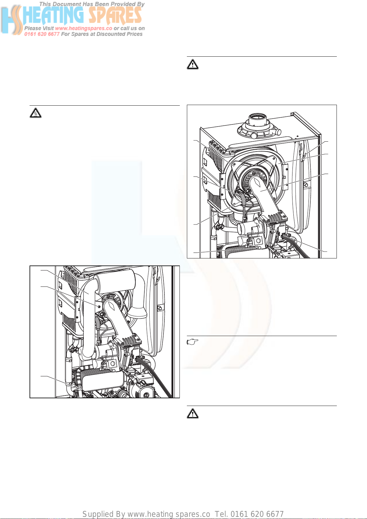
Supplied By www.heating spares.co Tel. 0161 620 6677
Inspection and maintenance 7
7.2 Servicing the burner module
7.2.1 Removing the burner module
The burner module consists of the burner, fan, gas valve
und the gas supply (mixer tube). These four components
make up the complete assembly, the burner module.
Danger!
There is danger of being injured or burnt by the
burner module and at all components carrying
water. Only carry out work on these components once they have cooled down.
Proceed as follows to remove it:
• Turn off the boiler
• Isolate the electrical supply to the boiler.
• Remove boiler bottom cover by releasing the two
spring retaining lugs and lowering the rear of the bottom cover.
• Gently pull the bottom cover backwards to remove
from the appliance.
• Turn off the gas service valve.
• Turn off the boiler CH service valves.
• Loosen screw, release the front case spring retaining
clips located beneath the front edge of the appliance.
• Remove the front casing by easing forward the bottom
edge and gently lifting.
• Lower electronic control box.
Caution!
Damage to corrugated gas pipe!
Under no circumstances must the burner module be suspended from the flexible corrugated
gas pipe.
4
5
6
7
11
10
9
8
1
2
3
Fig. 7.1 Dismantling air intake pipe
• Remove screw (2) and remove the air intake pipe (1).
• Disconnect the gas supply (3) on the gas valve. Ensure
the corrugated gas pipe does not twist by holding the
flattened section of the pipe, with an open ended
spanner, whilst loosening the union nut.
Fig. 7.2 Dismantling burner module
• Disconnect HT lead (5) and earth lead (6) from spark
electrode.
• Remove four nuts (4) from burner manifold.
• Disconnect two electrical connections (7 and 8) from
fan and gas valve.
• Pull forward and remove burner, gas valve and fan
assembly (9) from integral condensation heat
exchanger (10).
Note
You can suspend the burner module on the hook
(11) while carrying out maintenance tasks.
• After removing the thermal compact module, clean
the components as described below.
7.2.2 Cleaning the integral condensation heat
exchanger
Caution!
Protect the electronics box against sprayed
water.
39Instructions for installation and servicing ecoTEC
Page 40
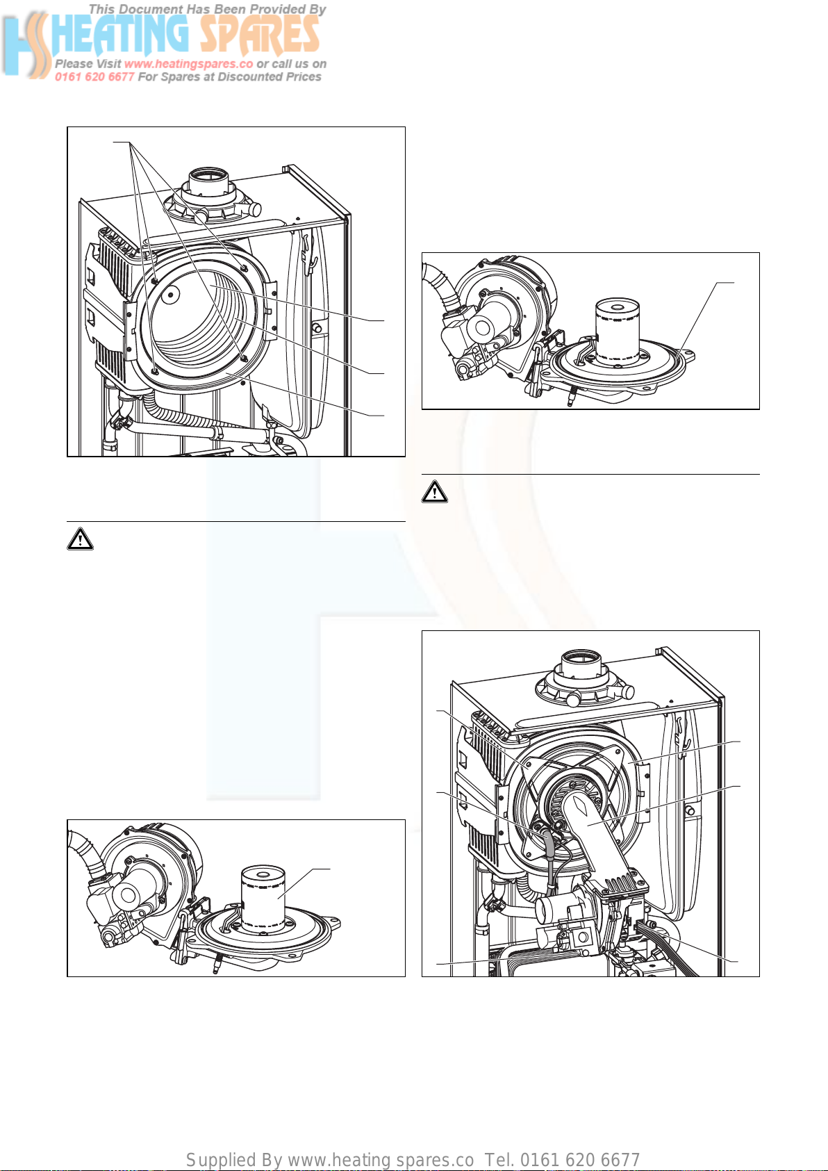
Supplied By www.heating spares.co Tel. 0161 620 6677
7 Inspection and maintenance
1
2
3
4
Fig. 7.3 Cleaning the integral condensation heat exchanger
• Dismantle the burner module as described under 7.2.1.
Caution!
Risk of damaging the primary heat exchanger!
Do not attempt to loosen nor retighten the four
screws (1).
With the burner and fan assembly removed it is now
possible to inspect the main heat exchanger (4).
• Remove any loose deposits from the heating spirals
(3) using a soft brush and jet of water (ensure that
water is kept away from all electrical components. Any
water used to clean the main heat exchanger will drain
through the condensate trap). Avoid pointing the
water jet directly at the insulating surface (2) on the
back of the heat exchanger.
If required the heat exchanger can be cleaned using regular vinegar.
7.2.3 Checking the burner
• Check the burner surface for damage, replace the
burner if necessary.
• After checking/replacing the burner, re-assemble the
burner module in the boiler as described in Section
7.2.4.
7.2.4 Refitting the burner module
Fig. 7.5 Replacing the burner door seal
• Insert a new seal (1) in the burner door.
Caution!
The burner door seal (1) and the self-locking
nuts on the burner module must be replaced
each time the module is removed (for example
during maintenance, see table 7.1). If the burner
flange insulation on the burner module shows
any signs of damage other small cracks it must
also be replaced.
4
5
1
10
9
1
6
7
Fig. 7.4 Checking burner
The burner (1) is maintenance-free and needs no cleaning.
Fig. 7.6 Refitting the burner module
• Insert the burner module (9) in the integral condensation heat exchanger (10).
40 Instructions for installation and servicing ecoTEC
8
Page 41
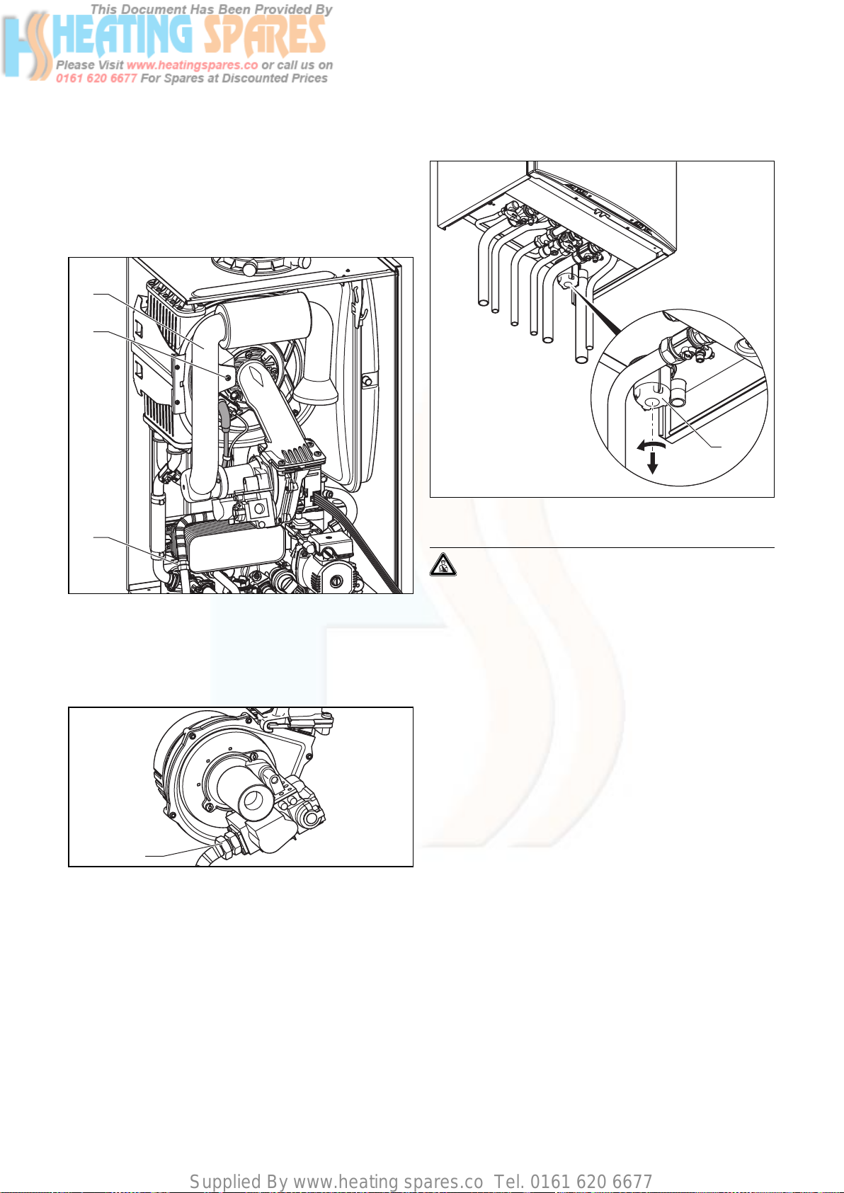
Supplied By www.heating spares.co Tel. 0161 620 6677
Inspection and maintenance 7
• Tighten the four nuts (4) on the alternate left and
right sides until the burner door fits closely and uniformly to the stop surfaces.
• Reconnect the HT lead (5) and earth lead (6) to the
spark electrode.
• Insert the cables (8) on the fan motor and the cable
(7) on the gas fitting.
1
2
3
Fig. 7.7 Refitting the gas supply
• Reconnect the gas supply (3) to the gas valve, ensuring that a new sealing washer is used and correctly
located. Use the spanner flat at the flexible gas line to
hold the gas fittings.
7.3 Cleaning the condensate siphon
1
Fig. 7.9 Cleaning the condensate siphon
Danger!
Note that if the boiler is run with an empty
condensate trap there is a danger that fumes
might escape into the room and cause poisoning. For this reason, it is important to ensure
that the trap is topped up each time the unit is
cleaned.
• Remove the lower part (1) of the condensate siphon by
turning the bayonet catch in anticlockwise direction.
• Clean the siphon part section by rinsing it out with
water.
• Fill the lower part with water until about 10 mm below
the upper edge.
• Fasten the lower part again on the condensate siphon.
11
Fig. 7.8 Testing the gas supply for soundness
• Turn on the gas supply and test for soundness. Check
especially the screwed connections (3) and (11).
• Refit the air inlet pipe, ensuring that the blue seal in
the air intake pipe is correctly located.
41Instructions for installation and servicing ecoTEC
Page 42

Supplied By www.heating spares.co Tel. 0161 620 6677
7 Inspection and maintenance
8 Troubleshooting
7.4 Checking the expansion vessel
Fig. 7.10 Checking expansion vessel admission pressure
Note
It is not necessary to perform this check every
year – a check every three years is sufficient.
• Fill out the Benchmark gas boiler commissioning
checklist at the rear of this guide.
1
Fig. 7.11 Function check
8 Troubleshooting
• Ensure the boiler CH service valves are closed.
• Release the pressure from the boiler.
• Remove valve cap from expansion vessel charge point.
• Check that the internal charge pressure of the expansion vessel is between 0.75 and 0.9 bar.
If the pressure is lower than this the vessel should be
repressurised using an air pump.
• Refit the valve cap.
• Repressurise boiler and heating system.
7.5 Recommissioning the boiler
• Carry out electrical safety checks.
• Turn on the electrical supply.
• Open the boiler CH service valves.
• Carry out function checks of boiler operation as previously detailed.
• Check gas rate as previously detailed.
• Check for water leaks.
• Refit case, ensuring that a good seal is obtained.
7.6 Test operation
Always perform the following checks after completing
any maintenance task:
• Commission the appliance according to the relevant
operating manual.
• Check the appliance for gas and water leaks.
• Check the air/flue gas system for leaks, check its fastening
• Check for ignition and an even flame on the burner.
• Check that the heating system and the water heating
is working (combination boilers only).
8.1 Logical fault finding procedure
These checks must be carried out before attempting to
use the fault finding guide.
1. Carry out electrical safety checks (see section
‘Preliminary Electrical Checks’).
2. Check that the external electricity supply to the boiler
is on, and a supply of 230 V~ is present between boiler
terminals ‘L’ and ‘N’.
3. Check that the gas supply to the boiler is on, that it
has been correctly purged and that an inlet pressure
of 20 mbar is available at the gas valve. (See section
‘Gas Supply’).
4. Ensure the heating system is full of water and charged
to between 1 and 1.5 bar. If not, refill and vent the system. (See section ‘Filling the heating system’). Ensure
boiler flow and return service valves are open.
5. Check that the main on/off control is set to the ‘on’
position.
6. Set the central heating temperature to maximum.
7. Set the domestic hot water temperature to maximum
(combination boilers only).
8. Check that all external controls are on and calling for
heat (if no external controls are fitted, boiler terminals
3 and 4 must be linked). Check that the boiler anti–
cycling economiser is not engaged.
42 Instructions for installation and servicing ecoTEC
Page 43

Supplied By www.heating spares.co Tel. 0161 620 6677
Troubleshooting 8
8.1.1 Status codes
The status codes that you can see on the display provides information about the current operating condition
of the appliance.
The display of the status codes can be called as follows:
plus pro
Fig. 8.1 Display of status codes
• Press the “i” key.
The display shows the status code, e.g. S.4 for “Burner
mode - Heating”.
The display of the status codes can be cancelled as follows:
• Press the “i” key
or
• Do not press any key for about 4 minutes.
The current heating flow temperature appears in the
display again.
Display Meaning
Heating mode (all models):
S. 0 No heat demand
S. 1 Fan running
S. 2 Water pump running
S. 3 Ignition sequence
S. 4 Burner ignited
S. 5 Fan and pump running
S. 6 Fan over run
S. 7 Pump over run
S. 8 Anti cycling mode
Domestic hot water mode (ecoTEC combination boilers only):
S.10 Hot water demand
S.11 Fan running
S.13 Ignition sequence
S.14 Burner ignited
S.15 Fan and pump running
S.16 Fan over run
S.17 Pump over run
Table 8.1 Status codes
Display Meaning
Warm start (ecoTEC combination boilers only) / Charge hot
water cylinder (ecoTEC system boilers only):
S.20 Warmstart demand
S.21 Fan running
S.22 Pump running
S.23 Ignition sequence
S.24 Burner ignited
S.25 Fan and water pump running
S.26 Fan over run
S.27 Pump over run
S.28 Anti cycling mode
All boilers:
S.30 No heating demand from external controls (clamp 3-4
open)
S.31 Central heating thermostat knob turned off or no heat
demand by the eBUS control unit
S.32 Heat exchanger antifreeze active, as fan speed varia-
tion is too high. Appliance is within the waiting time of
the operation block function
S.34 Antifrost mode active
S.36 No heating demand from low voltage controls (clamp
7-8-9)
S.41 Water pressure > 2,9 bar
S.42 Response from accessory modul or defective conden-
sate pump is blocking burner operation
S.52 Water pressure > 2,9 bar
S.53 Appliance is within the waiting period of the operation
block function due to water shortage (VL-RL spread too
big)
S.54 Appliance is within the waiting period of the operation
block function due to water shortage (temperature
gradient)
S.96 Return-sensor check is running, demand (DHW or heat-
ing) is blocked
S.97 Water pressure sensor check is running, demand (DHW
or heating) is blocked
S.98 Flow-/Return-sensor check is running, demand (DHW or
heating) is blocked
Table 8.1 Status codes (continued)
8.1.2 Diagnostic codes
In the diagnostic mode, you can change certain parameters or display more information.
The diagnostic information is divided into two diagnostic
levels. The second diagnostic level can be reached only
after entering a password.
Caution!
Access to the second diagnostic level must be
used exclusively by a qualified technician.
43Instructions for installation and servicing ecoTEC
Page 44

Supplied By www.heating spares.co Tel. 0161 620 6677
8 Troubleshooting
First Diagnostic level
• Press the “i” and “+” keys simultaneously.
The display shows “d.0”.
You can end the diagnostic mode as follows:
• Press the “i” and “+” keys simultaneously.
or
• Do not press any key for approx. 4 minutes.
• Use the “+” or “–” keys to scroll through the desired
diagnostic numbers of the first diagnostic level (see
table 8.2).
The current heating flow temperature appears in the display again.
• Press the “i” key.
The display shows the relevant diagnostic information.
• If necessary, use the “+” or “–” keys to change the
value (display flashes).
• Save the new value by holding down the “i” key for
approx. 5 seconds until the display no longer flashes.
Display Meaning Display value/adjustable value
d. 0 Heating part load Adjustable heating part load in kW (factory setting: max. output)
d. 1 Water pump over run time for heating mode 2 - 60 min (factory setting: 5 min)
d. 2 Max. burner anti cycling period at 20 °C Flow tempera-
ture
d. 3 Hot water flow temperature reading (combination boiler
only)
d. 4 Current temperature for warm start sensor
(combination boilers only)
Current storage tank sensor (system boilers only)
d. 5 Flow temperature target value or return target value
when return regulation is set.
d. 6 Hot water temperature target value in °C, 35 to 65 °C
d. 7 Warm start temperature target value
(ecoTEC plus combination boiler only)
Storage temperature target value (system boiler only)
d. 8 External controls heat demand (Clamp 3-4) 0 = open (no heat request)
d. 9 Flow target temperature from external analogue regula-
tor to terminal 7-8-9/eBUS
d.10 Status internal heating pump 1 = on, 0 = off
d.11 Status external heating pump 1 to 100 = on, 0 = off
d.12 Cylinder charging pump (via accessory module) 1 to 100 = on, 0 = off
d.13 Hot water circulation pump (via accessory module) 1 to 100 = on, 0 = off
d.22 Hot water demand 1 = on, 0 = off
d.23 Summer/Winter function 1 = Winter, 0 = Summer
d.25 Hot water activation via eBUS Control 1 = yes, 0 = no
d.30 Control signal for both gas valves 1 = on, 0 = off
d.33 Fan speed target value in rpm/10
d.34 Fan speed actual value in rpm/10
d.35 Position of diverter valve (combination boilers only) 0 = Heating; 100 = Hot water; 40 = Centre position
d.36 Hot water flow sensor in l/min
d.40 Flow temperature Actual value in °C
d.41 Return temperature Actual value in °C
d.44 Digitised ionisation potential Display range of 0 to 102, > 80 no flame, < 40 even flame
d.47 Outside temperature
(with weather compensating Vaillant controller only)
d.67 Remaining burner anti cycling time in min
d.76 Appliance variant (device specific number) 00 to 99
d.90 Digital regulator status 1 = identified, 0 = unidentified (eBUS Address <=10)
d.91 DCF status with connected external probe with DCF77
receiver
d.97 Activation of the second diagnostic level Password: 17
Table 8.2 Diagnostic codes of the first diagnostic level
2 - 60 min (factory setting: 20 min)
in °C
in °C
in °C, max. the value set in d.71
Limited by the eBUS controller (if an eBUS controller is connected)
in °C, 40 to 65 °C
in °C, 15 °C for left stop, then 40 to 70 °C
1 = closed (heat request)
in °C, minimum from ext. eBUS target value and target value terminal
7
Actual value in °C
0 = no reception, 1 = reception, 2 = synchronised, 3 = valid
44 Instructions for installation and servicing ecoTEC
Page 45

Supplied By www.heating spares.co Tel. 0161 620 6677
Troubleshooting 8
Second diagnostic level
• As described above in the first diagnostic level, scroll
Scrolling and changing values and exiting the diagnostic
mode is done as described in the first diagnostic level.
through the diagnostic number d.97.
• Change the displayed value to 17 (password) and press
the “i” button.
Note
After exiting the second diagnostic level, if you
press “i” and “+” within 4 minutes, you will
You are now in the second diagnostic level where all
information from the first diagnostic level (see table 8.2)
directly reach the second diagnostic level without having to enter the password again.
and the second diagnostic level (see table 8.3) is displayed.
Display Meaning Display value/adjustable value
d.17 Heating flow/return regulation changeover 0 = flow, 1 = return (factory setting: 0)
d.18 Pump mode (return) 0 = return, 1 = nonstop, 2 = winter (factory setting: 0)
d.19 Only in ecoTEC plus:
Operating modes of the two-speed heating pump
d.20 Maximum set value for target cylinder temperature
(system boilers only)
d.27 Switching accessory relay 1 in the accessory module 1 = Circulation pump (default)
d.28 Switching accessory relay 2 in the accessory module 1 = Circulation pump
d.50 Offset for minimum speed in rpm/10, adjustment range: 0 to 300
d.51 Offset for maximum speed in rpm/10, adjustment range: -99 to 0
d.58 From the third quarter of 2006:
Activation of solar reheating
d.60 Number of safety temperature limiter cut offs Quantity
d.61 Number of lock outs Number of unsuccessful ignitions in the last attempt
d.64 Average ignition time in seconds
d.65 Maximum ignition time in seconds
d.68 Unsuccessful ignitions in the first attempt Quantity
d.69 Unsuccessful ignitions in the second attempt Quantity
d.70 Set diverter valve position 0 = Normal mode (factory setting)
d.71 Maximum setting of heater control knob Adjustment range in °C: 40 to 85 (Factory setting: 75)
d.72 Pump overrun time after warm start (combination boil-
ers only) or charging an electronically controlled hot
water storage through C1-C2 (system boilers only)
d.73 Offset for warm start target value (combination boilers
only)
d.75 Maximum charging time for a storage without own con-
troller (system boilers only)
d.77 Storage partial load (storage charging capacity limit,
system boilers only)
Table 8.3 Diagnostics codes of the second diagnostic level
0 = pre ignition speed 1, hot water or heating speed 2, overrun speed
1
1 = pre ignition speed 1, hot water speed 2, heating speed 1, overrun
speed 1
2 = like 1, but speed in heating mode dependent on heating part load
d. 0 (if d.0 is below 60% of full load, then pump speed 1, other-
wise speed 2)
3 = always speed 2
(factory setting: 2)
Setting range: 50 to 70 °C (factory setting: 65 °C)
2 = Ext. pump
3 = Storage charging pump
4 = Flue gas flap/extractor hood
5 = External gas valve
6 = External error message
2 = Ext. pump (default)
3 = Storage charging pump
4 = Flue gas flap/extractor hood
5 = External gas valve
6 = External error message
Setting range: 0 to 3
0 = solar reheating disabled (factory setting)
3 = activation of min. hot water target value = 60 °C for solar
reheating
1 = Centre position
2 = permanent heating position
Adjustment range in sec: 0, 10, 20 to 600
Factory setting for combination boilers: 80
Factory setting for system boilers: 300
Adjustment range: -15 K to +5 K (Factory setting: 0 K)
Adjustment range in min: 20, 21, 22 to 90 (Factory setting: 45)
Adjustment range in kW: appliance-specific
Factory setting: max. output
45Instructions for installation and servicing ecoTEC
Page 46

Supplied By www.heating spares.co Tel. 0161 620 6677
8 Troubleshooting
Display Meaning Display value/adjustable value
d.78 Storage charging temperature limit (target flow tem-
perature in storage mode, system boilers only)
d.80 Heating operating hours in h
Adjustment range in °C 55 to 90 (Factory setting: 80)
1)
d.81 Water heating operating hours (combination boilers
only)
d.82 Cycles in heating mode Quantity/1001) (3 corresponds 300)
d.83 Cycles in hot water operation Quantity/100
d.84 Maintenance indicator: Number of hours until the next
maintenance
d.93 DSN appliance variant setting Adjustment range: 0 to 99
d.96 Factory setting 1 = Resetting adjustable parameters to factory setting
1) Five-digit numbers are saved with the diagnostics codes 80 to 83. If d.80, for example, is selected, only the first two digits of the
number are displayed (e. g. 10). The display switches to the last three digits (e. g. 947) by pressing “i”. In this example the number of
operating hours of the heating is 10947 h. The display returns to the selected diagnostics item by pressing “i” again.
Table 8.3 Diagnostics codes of the second diagnostic level
(continued)
1)
in h
1)
(3 corresponds 300)
Adjustment range: 0 to 3000 h and “-” for disabled
Factory setting: “-” (300 corresponds to 3000 h)
8.1.3 Fault codes
Fault codes take priority over all other display functions
in the event of a system fault occurring.
If multiple faults occur, the corresponding fault codes
are displayed alternately for about two seconds each.
8.1.4 Fault memory
The fault memory stores details of the ten most recent
faults.
• Press the ”i” and ”–” buttons simultaneously.
• Use the ”+” button to scroll back through the list of
memorised errors.
To cancel fault error memory display mode, proceed as
follows:
• Press the ”i” button below the display or
• Do not touch any key for about four minutes. The display will now revert back to showing the current flow
temperature.
Code Meaning Cause
F. 0 Flow–NTC open circuit NTC broken, NTC cable broken, Defective connection at NTC,
F. 1 Return–NTC open circuit NTC broken, NTC cable broken, Defective connection at NTC,
F.10 Flow NTC short circuit NTC defective, short circuit in cable harness, cable/casing shortcut
F.11 Return NTC short circuit NTC defective, short circuit in cable harness, cable/casing shortcut
F.13 Tank NTC short circuit NTC defective, short circuit in cable harness, cable/casing shortcut
F.20 Safety temperature limiter by NTC activated Flow-NTC not correctly thermal-connected or defective; appliance
F.22 Dry fire Too little water in the appliance, water pressure sensor defective,
F.23 Water shortage, temperature difference between flow
and return NTC too large
F.24 Water shortage, temperature rise too quick Pump blocked, insufficient pump output, air in appliance, water
Table 8.4 Error codes
Defective connection at electronics
Defective connection at electronics
does not shut down
cable to pump or water sensor defective, pump blocked or defective, pump output too low
Pump blocked or defective, pump output too low, flow and return
NTC interchanged
pressure too low
46 Instructions for installation and servicing ecoTEC
Page 47

Supplied By www.heating spares.co Tel. 0161 620 6677
Code Meaning Cause
F.25 Interruption in the compact thermal module cable har-
ness
F.27 Incorrect sensing of flame Flame detector defective
F.28 Appliance does not start: Attempts to ignite during start
failed
F.29 Flame goes off during operation and subsequent ignition
attempts failed
F.32 Fan speed variation Fan blocked, plug not inserted correctly on fan, hall sensor defec-
F.49 eBUS undervoltage Short circuit on eBUS, overload on eBUS or two power sources on
F.61 Gas–valve control defective Short circuit/earth (ground) leak in cable harness to gas valves, gas
F.62 Gas valve shutoff delay Gas valve leaking, electronics defective
F.63 EEPROM error Electronics defective
F.64 Electronics/NTC fault Short-circuit in flow or return NTC or electronics defective
F.65 Electronics temperature too high Electronics too hot due to external effect, electronics defective
F.67 Flame detector input signal is outside the limits
(0 or 5 V)
F.70 No valid DSN in display and/or mainboard Spare part failure display and maiboard interchanged at same time
F.71 Flow NTC reports constant value (stuck at) Flow NTC is defective
F.72 Flow and/or return NTC fault Flow and/or return NTC is defective (tolerances too big)
F.73 Water pressure sensor signal out of range (too low) Cable to water pressure sensor is broken or has a short-circuit at
F.74 Water pressure sensor signal out of range (too high) Cable to water pressure sensor has a short-circuit at 5 V / 24 V or
F.75 No pressure rise was detected on turning on the pump Water pressure sensor or/and pump defective
F.76 Overheating protection on primary heat exchanger trig-
gered
F.77 condensate pump or feedback of accessorie blocks heat-
ing
F.78 wrong configuration with accessory link box VR65 connected to combination boiler
con no communication to mainboard connection error display mainboard
Table 8.4 Error codes (continued)
Compact thermal module cable harness defective
Faults in the gas supply such as:
- Gas meter or gas pressure detector defective
- Air in gas
- Gas flow pressure too low
- Fire protection tap has disengaged
Faults in the gas valve, wrong gas setting, igniter (ignition transformer, ignition cable, ignition plug) defective, ionisation current
stopped (cable, electrode), faulty earthing in appliance, electronics
defective
Gas supply temporarily stopped, faulty earthing of appliance
tive, fault in cable harness, electronics defective
eBUS with different polarity
valve assembly defective (earth/ground leak from coils), electronic
control system defective
Electronics defective
and device specific number not adjusted
0 V or water pressure sensor defective
internal fault in water pressure sensor
Air in the heating system, quick bleeder defective
Too little water in appliance; check adjustable by-pass; connect
external expension vessel to return
Cable or cable connection of fuse in the primary heat exchanger
defective, or primary heat exchanger defective
condensate pump defective or flume flap feedback triggered
Troubleshooting 8
47Instructions for installation and servicing ecoTEC
Page 48
Supplied By www.heating spares.co Tel. 0161 620 6677
8 Troubleshooting
9 Parts replacement
8.4 Test programs
Special functions can be triggered on the appliances by
activating various test programs.
These programs are given in detail in the
Table 8.5.
• The test programs P.0 to P.6 will be started when
“Power ON” is turned on and the “+” key is pressed
for 5 s. The display shows “P.0”.
• Press the “+” key to start counting the test number
upwards.
• Press the “i” to operate the appliance now and to start
the test program.
• Press “i” and “+” simultaneously to exit the test programs. You can also exit the test programs by not
pressing any key for 15 minutes.
Display Meaning
P.0 Bleeding test program. The heating circuit and hot
water circuit (combination boiler only) is bled via the
automatic air vent (the cap on the automatic air vent
must be loosened).
P.1 Test program where the appliance is operated in full
load after successful ignition
P.2 Test program where the appliance is operated with
minimum gas volume (ignition gas volume) after successful ignition
P.3 not available
P.4 not available
P.5 Test program for the safety temperature limit check;
appliance heats up by by-passing a regulating shutdown through the flow regulator until the shutoff temperature of 97 °C is achieved.
P.6 Filling test program. The diverter valve moves to the
centre position
Table 8.5 Test programs
8.5 Resetting parameter to factory settings
Besides the option to reset individual parameters manually to the factory settings specified in tables 8.2 and
8.3, you can also reset all parameters simultaneously.
• In the second diagnostic level, under the diagnostic
number “d.96” change the value to 1 (see section
8.1.2).
The parameters of all adjustable diagnostic numbers
now correspond to the factory settings.
9 Parts replacement
The tasks listed below in this section may be carried out
only by a qualified engineer.
• Only use genuine spare parts for repairs.
• Make sure the parts are correctly fitted and that their
original position and alignment are retained.
9.1 Safety instructions
Danger!
Each time the components are replaced, comply
with the safety instructions below for your own
safety and to avoid damage to the appliance!
• Put the appliance out of operation.
Important:
Before starting any maintenance work:
Isolate the mains electricity supply by disconnecting the plug at the socket outlet (if there is
only an isolating switch remove the fuse from
the switch).
• Close the service valve in the gas supply as well as the
service valves in the heating flow and return pipe.
• Close the service valve in the cold water supply line
(combination boilers only)!
• Empty the appliance if you want to replace water-bearing components of the appliance!
• Make sure that no water drops on live components
(e.g. switch box etc.)!
• Use only new seals and O-rings!
• After completing the work, check for gas leaks and
perform a function check (see section 7.6)!
• Always check earth continuity, polarity and resistance
to earth with a multimeter after any service work and
after exchanging any electrical component.
9.2 Replacing burner
Danger!
Before replacing the component, comply with
the safety instructions in Section 9.1.
• Dismantle the burner module as described in Section
7.2.1.
48 Instructions for installation and servicing ecoTEC
Page 49
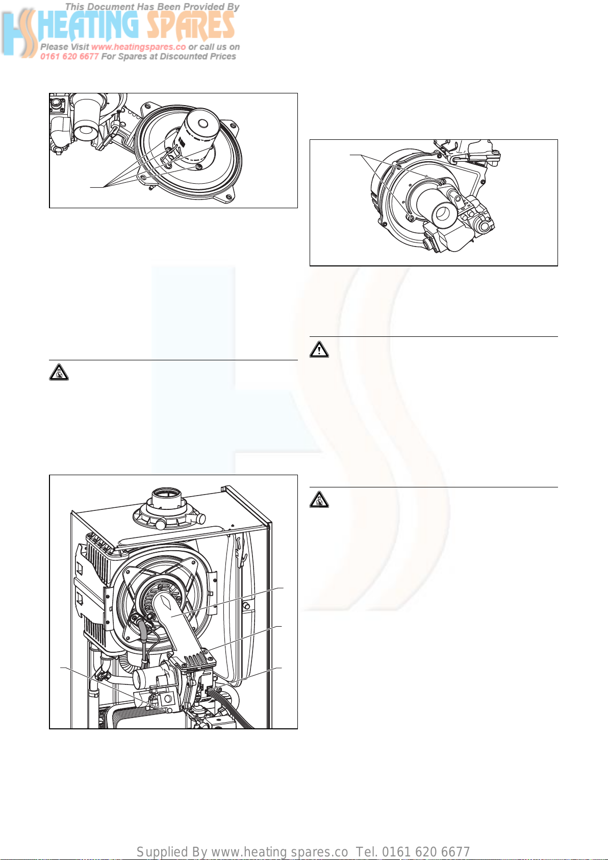
Supplied By www.heating spares.co Tel. 0161 620 6677
1
Fig. 9.1 Replacing burner
• Loosen the 4 screws (1) on burner, and remove the
burner.
• Mount the new burner with a new seal. Ensuring that
the notch in the burner aligns with the burner viewing
window.
• Install the burner module as described in Section 7.2.4.
• After completing the work, check for gas leaks and
perform a function check (see section 7.6)!
Parts replacement 9
• Remove the three screws (2) on the burner module
(1).
• Remove the complete “gas valve/fan” unit.
5
Fig. 9.3 Gas fitting/fan screwed joint
• Remove both fixing screws (5) on the gas valve and
remove the fan from the gas valve.
• Replace the defective component.
9.3 Replacing fan or gas valve
Danger!
Before replacing the component, comply with
the safety instructions in section 9.1.
• Turn off the boiler.
• Isolate the electrical supply to the boiler
• Remove the air intake pipe (Fig. 7.1, Pos. 2).
• Loosen the gas supply pipe on the gas fitting (Fig. 7.2,
Pos. 3).
1
2
Caution!
Mount the gas valve and the fan in the same
position as before.
• Screw on the fan with the gas valve. Please use new
seals.
• Install the complete “gas valve/fan” unit in reverse
sequence.
• After completing the work, check for gas leaks and
perform a function check (see section 7.6)!
9.4 Replacing expansion vessel
Danger!
Before replacing the component, comply with
the safety instructions in Section 9.1.
• Disconnect the appliance from the mains as described
in Section 9.1, and close the service valve in the gas
supply pipe.
• Close the flow and return service valves and drain the
water from the boiler.
4
Fig. 9.2 Dismantling fan with gas fitting
• Pull out the plug (4) from the gas valve.
• Pull out the plug (3) from the fan.
3
49Instructions for installation and servicing ecoTEC
Page 50
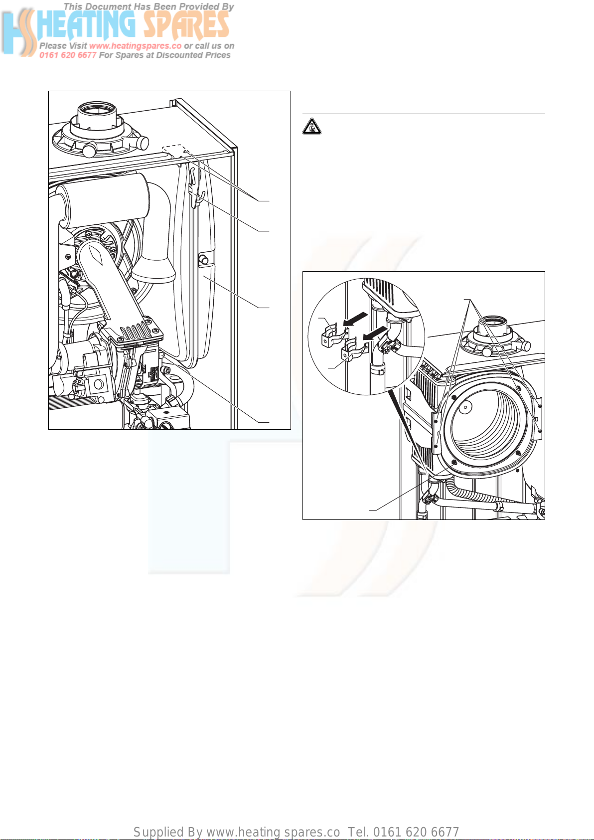
Supplied By www.heating spares.co Tel. 0161 620 6677
9 Parts replacement
9.5 Replacing primary heat exchanger
Danger!
Before replacing the component, comply with
the safety instructions in Section 9.1.
• Disconnect the appliance from the mains as described
in Section 9.1, and close the service valve in the gas
supply pipe.
• Close the flow and return service valves and drain the
1
appliance.
• Remove the burner module as described under 7.2.1.
2
• Remove the expansion vessel as described under 9.4.
• Pull out the condensate pipe to the siphon from the
primary heat exchanger.
3
4
Fig. 9.4 Replacing expansion vessel
• Undo the nut (4) on the water pipe on the lower side
of the expansion vessel.
• Remove both screws (1) retaining plate (2) and remove
the retaining plate.
• Pull out the expansion vessel (3) forwards.
• Guide the new expansion vessel back into the appliance.
• Re-connect the new expansion vessel using a new seal.
• Refix the retaining plate.
• Check the pressure of the expansion vessel (minimum
pressure 0.75 bar).
If necessary, adjust the pressure to the static height of
the heating system.
• Fill and vent the boiler.
• After completing the work, check for water leaks and
perform a function check (see section 7.6)!
3
1
2
4
Fig. 9.5 Replacing primary heat exchanger
• Pull out the clamps (1) and (2) and free the return pipe
as well as the flow pipe on the primary heat exchanger.
• Remove the four screws (3) on the primary heat
exchanger holder.
50 Instructions for installation and servicing ecoTEC
Page 51
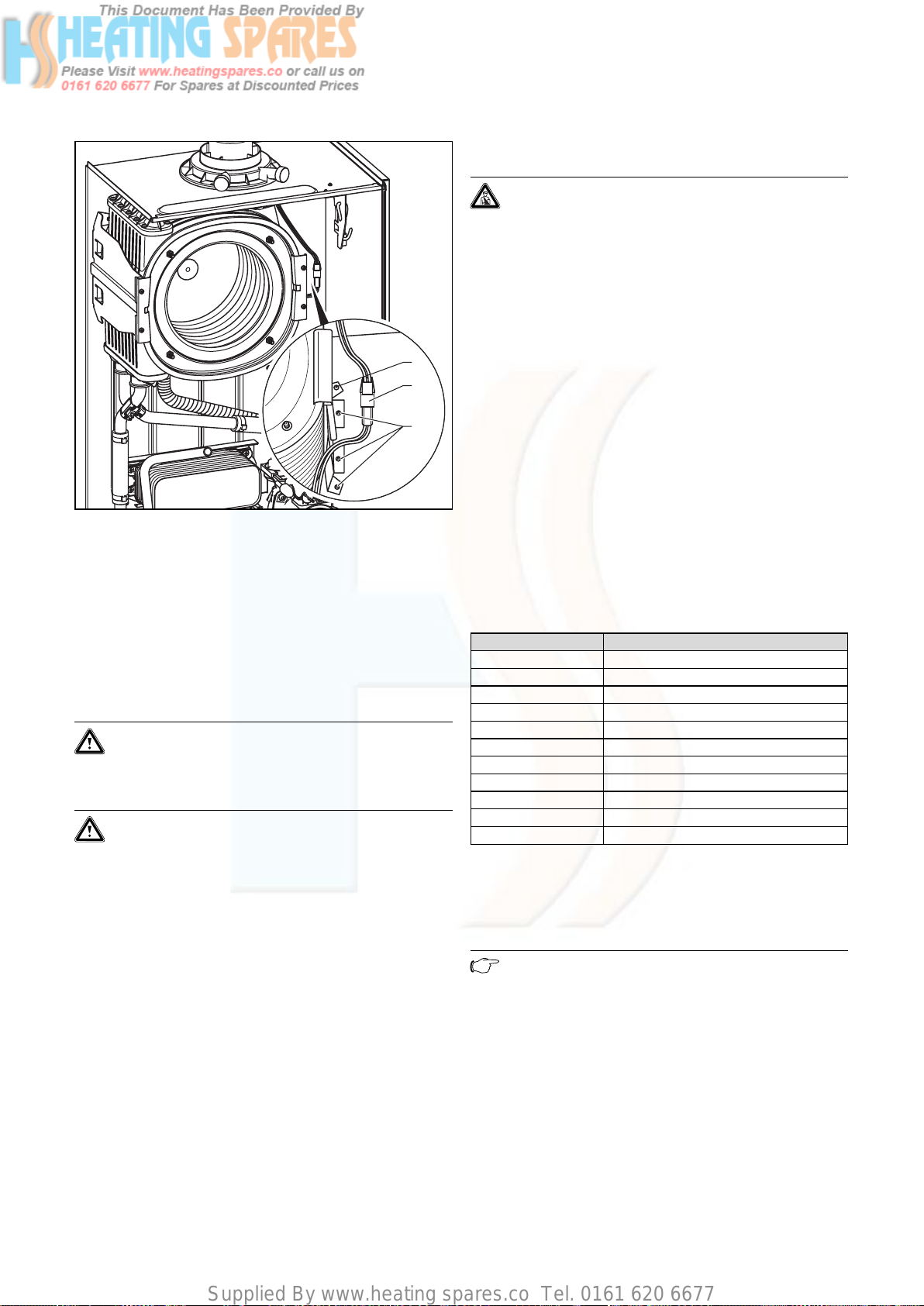
Supplied By www.heating spares.co Tel. 0161 620 6677
Parts replacement 9
9.6 Replacing electronics and display
Danger!
Before replacing the component, comply with
the safety instructions in Section 9.1.
• Comply with the assembly and installation manuals
provided with the spare parts.
Replacing display or electronics
If you are replacing only one of the two components, the
parameter adjustment functions automatically. On turn-
1
2
ing on the appliance, the new component takes over the
previously set parameters from the components that are
not replaced.
3
Fig. 9.6 Primary heat exchanger holder
• Disconnect the plug-in connection (2) of the thermal
fuse in the primary heat exchanger.
• Remove the three screws (3) on the primary heat
exchanger holder.
• Turn the holder to the side around the rivet (1), pull
the primary heat exchanger downwards to the right
and remove it from the appliance.
• Mount the new primary heat exchanger in reverse
order and replace the seals.
Caution!
Risk of damaging the primary heat exchanger!
Neither loosen nor retighten the four screws
(Fig. 9.5, Pos. 4).
Caution!
Insert the seal rings for the flow and return
pipe on the primary heat exchanger with a suitable lubricant.
Insert the flow and return connection in the primary heat exchanger as far as they will go and
make sure the clamps are fitted correctly on
the flow and return pipe (see fig. 9.5).
• Fill and vent the boiler as required.
• After completing the work, check for gas and water
leaks and perform a function check (see section 7.6)!
Replacing display and electronics
When replacing both components, after being turned on,
the appliance goes to fault and displays the error message “F70”.
• In the second diagnostic level, under the diagnostic
number “d.93” enter the number of appliance variant
according to Table 9.1 (see section 8.1.2).
The electronics is now set to the appliance type and the
parameters of all adjustable diagnostics numbers correspond to the factory settings.
Appliance Device specific number
ecoTEC plus 612 0
ecoTEC plus 615 1
ecoTEC plus 618 2
ecoTEC plus 624 3
ecoTEC plus 630 4
ecoTEC plus 637 5
ecoTEC plus 824 6
ecoTEC plus 831 7
ecoTEC plus 837 8
ecoTEC pro 24 7
ecoTEC pro 28 0
Table 9.1 Device specific numbers
9.7 Check CO2 content and if necessary set (airratio adjustment)
Note
Checking/adjustment of this value is required in
the following instances: replacement of gas
valve, conversion to or from Natural Gas/LPG
or if incorrect combustion is suspected!
• Remove the front cover.
• Press the “+” and “-” keys simultaneously.
The “Full load mode” is activated.
• Wait at least 5 minutes until the appliance reaches its
operating temperature.
51Instructions for installation and servicing ecoTEC
Page 52
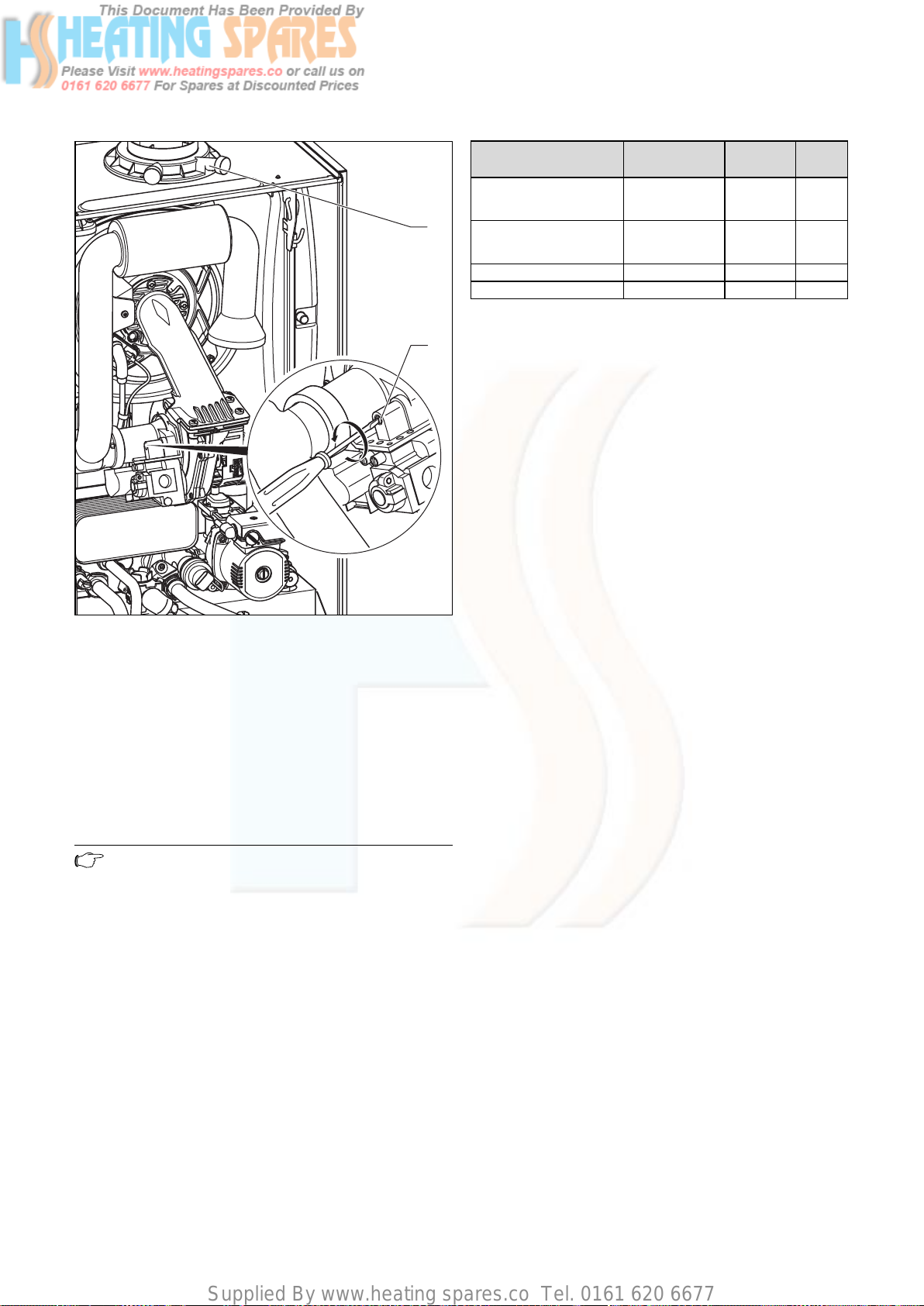
Supplied By www.heating spares.co Tel. 0161 620 6677
9 Parts replacement
10 Recycling and disposal
11 Vaillant service
Settings Natural gas (H)
CO2 after 5 min. full load
mode with appliance front
closed
1
CO
after 5 min. full load
2
mode with appliance front
removed
Set for Wobbe-Index W
CO value with full load < 250 < 250 ppm
Table 9.2 Factory gas settings
2
0
Tolerance
9.2 ± 1,0 10.2 ± 0,5
9.0 ± 1,0 10.0 ± 0,5
15 22.5 kWh/m
Propane
Tolerance
10 Recycling and disposal
Both the Vaillant ecoTEC and the associated transport
packaging consist primarily of recyclable raw materials.
The Vaillant ecoTEC and all accessories and packaging
must not be disposed of in the normal household rubbish. Make sure that the old unit and any existing accessories and the transport packaging is handed over to a
proper disposal organisation.
11 Vaillant service
Unit
Vol.–%
Vol.–%
3
Fig. 9.7 Carrying out measurement of CO2 levels, preparing for
air-ratio adjustment
• Measure the CO2 content on the flue gas measuring
nozzles (1).
• If necessary, loosen the screw and fold the suction
pipe extension forwards by 90° (don‘t remove!).
• If necessary, set the corresponding flue gas value
(value with removed appliance front, see table 9.2) by
turning the screw (2).
-> Turn to the left: higher CO
-> Turn to the right: lower CO
content,
2
content,
2
Note
Only for natural gas:
Adjust only in increments of 1/8 turn and wait
approx. 1 minute after each adjustment until
the value stabilises.
Only for liquid gas:
Adjust only in very small increments (approx.
1/16 turn), and wait approx. 1 minute after each
adjustment until the value stabilises.
• Fold back the suction pipe extension upwards.
• Check the CO
content again.
2
• If necessary, repeat setting.
• Press the “+” and “-” keys simultaneously.
The “Full load mode” is turned off. The full load mode
is also turned of if no key is pressed for 15 minutes.
• Fasten the suction pipe extension.
• Attach the front cover again.
To ensure regular servicing, it is strongly recommended
that arrangements are made for a Maintenance
Agreement. Please contact Vaillant Service Solutions
(0870 6060 777) for further details.
52 Instructions for installation and servicing ecoTEC
Page 53

Supplied By www.heating spares.co Tel. 0161 620 6677
Appendix
Appendix
53Instructions for installation and servicing ecoTEC
Page 54
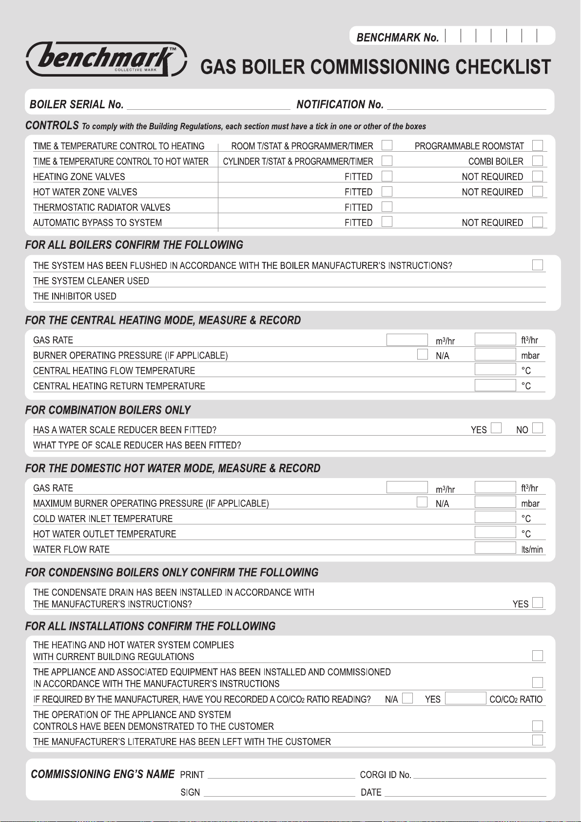
Supplied By www.heating spares.co Tel. 0161 620 6677
Page 55
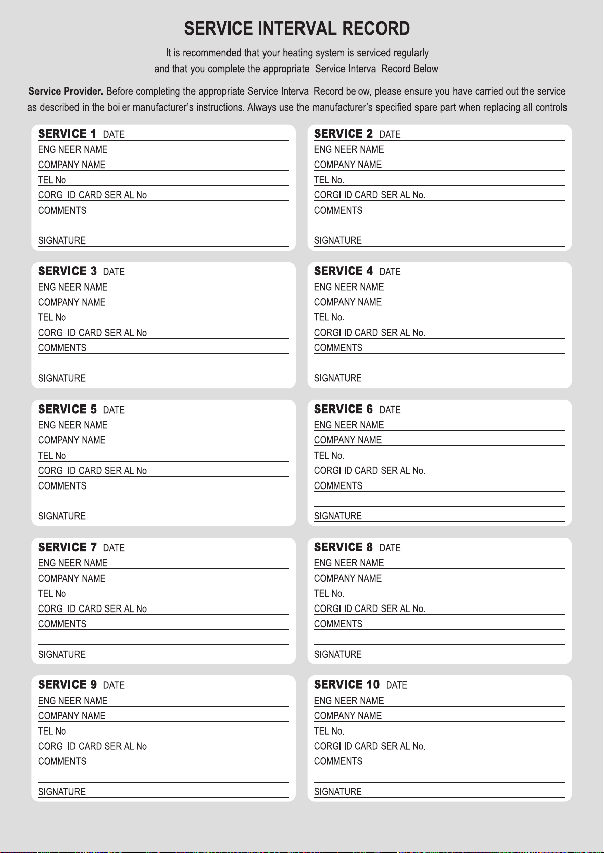
Supplied By www.heating spares.co Tel. 0161 620 6677
Page 56

Supplied By www.heating spares.co Tel. 0161 620 6677
839592_05 GB 08 2006
Page 57
Supplied By www.heating spares.co Tel. 0161 620 6677
For the installer
Flue installation instructions
Air flue duct for use with ecoMAX
and ecoTEC boilers
ecoMAX 613/2 E
ecoMAX 618/2 E
ecoMAX 622/2 E
ecoMAX 635/ E
ecoMAX 824/2 E
ecoMAX 828/2 E
ecoMAX 835/ E
ecoMAX pro 18 E
ecoMAX pro 28 E
ecoTEC plus 415
ecoTEC plus 418
ecoTEC plus 428
ecoTEC plus 438
ecoTEC plus 612
ecoTEC plus 615
ecoTEC plus 618
ecoTEC plus 624
ecoTEC plus 824
ecoTEC plus 630
ecoTEC plus 831
ecoTEC plus 637
ecoTEC plus 837
ecoTEC pro 24
ecoTEC pro 28
GB
Page 58

Supplied By www.heating spares.co Tel. 0161 620 6677
Page 59

Supplied By www.heating spares.co Tel. 0161 620 6677
OVERVIEW
PART 1 Pages 4 - 36
Standard Concentric Systems Ø 60/100
(Galvanized steel air duct/plastic flue duct)
PART 2 Pages 37 - 59
Optional Concentric System Ø 80/125
(Galvanized steel air duct/plastic flue duct)
PART 2 CONCENTRIC 80/125
PART 2 CONCENTRIC 80/125 PART 1 CONCENTRIC 60/100
Page 60

Supplied By www.heating spares.co Tel. 0161 620 6677
CONTENTS: PART 1 CONCENTRIC 60/100
The air/flue duct must be installed by a suitably
qualified service provider, which is responsible
for observing the relevant specifications,
regulations and standards.
Page
¤
Requirements
Planning the air/flue duct
layout
Regulations and standards to be observed 5
Alternative termination accessories available 6
Maximum flue lengths for ecoMAX 11
Maximum flue lengths for ecoTEC 12
Installing the air/flue duct sliding sleeve
Installation of the horizontal air/flue duct
Installation of the black terminal kit
Installation of the variable termination kit
14
15
21
23
Installation of the vertical air/flue duct
Fitting air/flue duct extensions
How to add extensions 31
How to install elbows 32
28
4
Page 61

Supplied By www.heating spares.co Tel. 0161 620 6677
REQUIREMENTS
¤
Regulations and
standards to be
observed
☞ Vaillant ecoMAX/ecoTEC boilers
are certified as heating boilers
with corresponding flue systems
according to EC Directive
90/396/EEC on gas-fired devices. This installation manual is
covered by this certification and is
referred to in the design approval
test certificate.
☞ These instructions should be read
in conjunction with the instructions
for installation and servicing
supplied with the boiler.
☞ Ensure also that all legislation,
rules, regulations and directives
mentioned in the installation
instructions are observed.
☞ The installation of the boiler and
its flue must be carried out by a
competent person who is
registered with CORGI (The
Council for Registered Gas
Installers).
☞ The air/flue duct operates at very
low temperatures therefore no
clearance is necessary between
the air duct and adjacent
services.
☞ Ensure while installation work is
being carried out that no debris
such as swarf, filings or fragments
of mortar are allowed to remain
in the air/flue duct.
PART 1 CONCENTRIC 60/100
☞ The installation of the boiler and
flue must be in accordance with
the Gas Safety (Installation and
Use) Regulations 1998 and the
Building Regulations and
BS 5440 Part 1.
☞ The requirements for flue
termination detailed in the boiler
installation instructions must be
observed.
☞ Two types of flue system are
available for ecoMAX/ecoTEC
boilers. The standard concentric
flue system (100 mm outside
diameter) and a larger diameter
concentric system (125 mm
outside diameter) which allows
longer air/flue duct lengths to be
achieved.
5
Page 62

Supplied By www.heating spares.co Tel. 0161 620 6677
PLANNING THE AIR/FLUE DUCT LAYOUT
Alternative termination accessories available
303 900 = Vertical air/flue duct (black)
Optional connection accessories
Air/flue duct extensions, concentric
470 mm - Ø 60/100
Air/flue duct extensions, concentric
970 mm - Ø 60/100
Air/flue duct extensions, concentric
1970 mm - Ø 60/100
Bends (PP), concentric (pack of 2)
45° - Ø 60/100
Elbow, concentric
87° - Ø 60/100
Flue support clips (pack of 5), Ø 100
Adjustable flue support clips (pack of 3); Ø 100
Sliding sleeve (PP) Ø 60/100
303 933 = Horizontal air/flue duct
303 936 = Horizontal telescopic air/flue duct
303 900
303 933
Accy. No.
303 902
303 903
303 905
303 911
303 910
303 821
303 935
303 915
x
x
x
x
x
x
x
x
x
x
x
x
x
x
x
x
303 936
x
x
x
x
x
x
x
x
Adjustable roof tiles for pitched roof
Flexible pitched roof seal
Flat roof penetration collar
Telescopic extension
440 mm - 690 mm Ø 60/100
Telescopic offset section
Black terminal kit for horizontal air/flue duct
Variable termination kit - black
Extension pipe for variable termination kit VTK
Ø 60 mm 1 m - black
*)
87° elbow for variable termination kit - black
*)
*)
45° bend for variable termination kit - black (2 pieces)
Variable termination kit - white
Extension pipe for variable termination kit VTK
Ø 60 mm 1 m - white
*)
*)
009076 black
303 980
009 056
303 906
303 919
303 934
303 942
303 943
303 944
303 945
303 946
303 947
x
x
x
x
x
x
x
x
x
x
x
x
x
x
x
x
x
x
x
x
x
x
x
x
x
87° elbow for variable termination kit - white
45° bend for variable termination kit - white (2 pieces)
*)
*) delivered with support clips
6
303 949
303 948
x
x
x
x
Page 63

Supplied By www.heating spares.co Tel. 0161 620 6677
PLANNING THE AIR/FLUE DUCT LAYOUT
Air/flue duct extension 470 mm
Ø 60/100
Vaillant Accy. No.: 303 902
Air/flue duct extension 970 mm,
Ø 60/100
Vaillant Accy. No.: 303 903
Air/flue duct extension 1970 mm,
Ø 60/100
Vaillant Accy. No.: 303 905
Fig. 1.1: Extensions, Ø 60/100
27
18
27
18
Fig. 1.2: Elbow joints, Ø 60/100
65
18
GU_LAZ 70/0
Elbow, 87°, Ø 60/100
Vaillant Accy. No.: 303 910
27
Bends, 45° (pack of 2),
Ø 60/100
Vaillant Accy. No.: 303 911
Elbow, 87°, Ø 60/100
Only Part of:
Vaillant Accy. No.: 303 933
Vaillant Accy. No.: 303 936
PART 1 CONCENTRIC 60/100
Fig. 1.3: Elbow joints, Ø 60/100
☞ Use one clip per extension to
support the air/flue duct.
Fig. 1.4: Flue support clips, Ø 100/Ø 80
13
GU_LAZ 72/0
Flue support clips, Ø 100 (pack of 5)
Vaillant Accy. No.: 303 821
GU_LAZ 72/0
7
Page 64
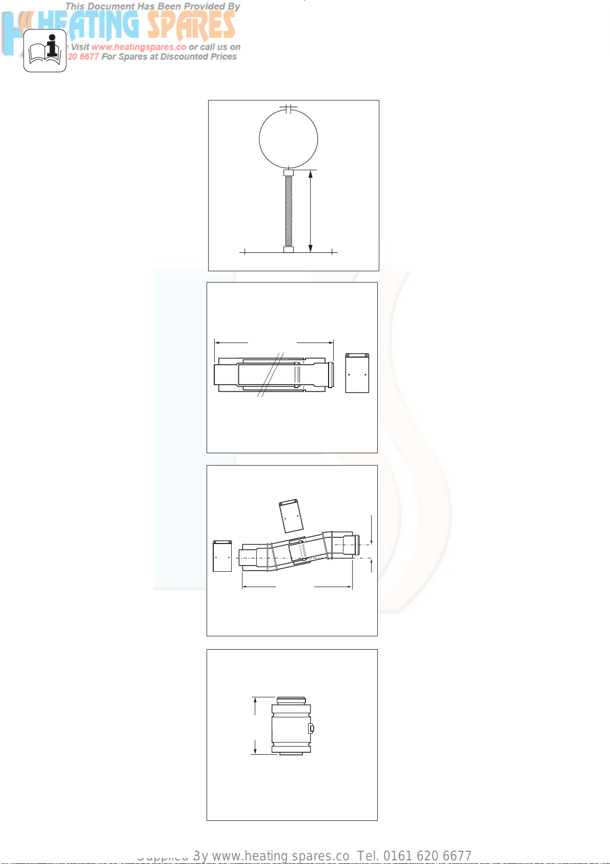
Supplied By www.heating spares.co Tel. 0161 620 6677
PLANNING THE AIR/FLUE DUCT LAYOUT
250
Fig. 1.5: Flue support clips, Ø 100
440 – 690
Adjustable flue support clips, Ø 100
(pack of 3)
Vaillant Accy. No.: 303 935
Telescopic extension (PP), Ø 60/100
440 mm - 690 mm
Vaillant Accy. No.: 303 906
Fig. 1.6: Telescopic extension, Ø 60/100
290 – 374
Fig. 1.7: Offset section, Ø 60/100
155
Offset section, Ø 60/100
Vaillant Accy. No.: 303 919
33 – 56
303919_IAx
Sliding sleeve (PP), Ø 60/100
Vaillant Accy. No.: 303 915
Fig. 1.8: Sliding sleeve, Ø 60/100
8
Page 65
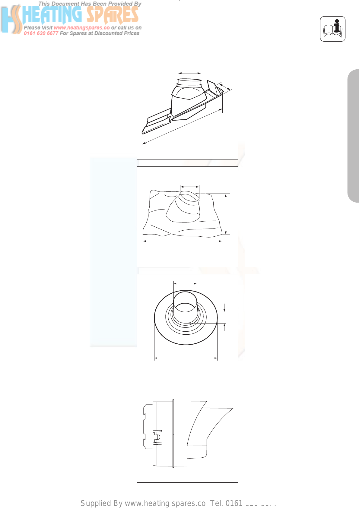
Supplied By www.heating spares.co Tel. 0161 620 6677
PLANNING THE AIR/FLUE DUCT LAYOUT
Adjustable roof tile for pitched roof
132
255
498
Vaillant Accy. No.: 009 076 (black)
Fig. 1.9: Adjustable roof tile for pitched roof
132
495
Fig. 1.10: Flexible pitched roof seal
130
GU_LAZ 41/0
Flexible pitched roof seal (black)
Vaillant Accy. No.: 303 980
PART 1 CONCENTRIC 60/100
495
Flat roof penetration collar
Vaillant Accy. No.: 009 056
153
390
Fig. 1.11: Flat roof penetration collar
Fig. 1.12: Black terminal kit
Black terminal kit for horizontal
air/flue duct
Vaillant Accy. No.: 303 934
For 303 933 and 303 936 only
9
Page 66
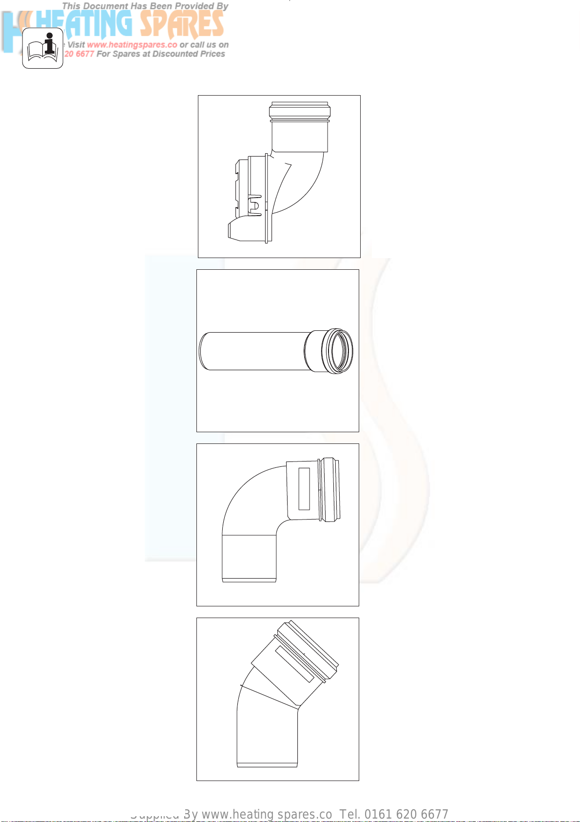
Supplied By www.heating spares.co Tel. 0161 620 6677
PLANNING THE AIR/FLUE DUCT LAYOUT
Fig. 1.13: Variable termination kit
Variable termination kit - black
Vaillant Accy. No.: 303 942
For 303 933 and 303 936 only
Variable termination kit - white
Vaillant Accy. No.: 303 946
For 303 933 and 303 936 only
Extension pipe for variable
termination kit Ø 60 mm 1 m - black
including 1 support clip
Vaillant Accy. No.: 303 943
Fig. 1.14: Extension Ø 60 1 m pipe
Fig. 1.15: 87° elbow
Extension pipe for variable
termination kit Ø 60 mm 1 m - white
including 1 support clip
Vaillant Accy. No.: 303 947
87° elbow for variable termination kit
- black
including 1 support clip
Vaillant Accy. No.: 303 944
87° elbow for variable termination kit
- white
including 1 support clip
Vaillant Accy. No.: 303 949
Fig. 1.16: 45° bend
10
45° bend for variable termination kit
- black
Vaillant Accy. No.: 303 945
45° bend for variable termination kit
- white
Vaillant Accy. No.: 303 948
Page 67
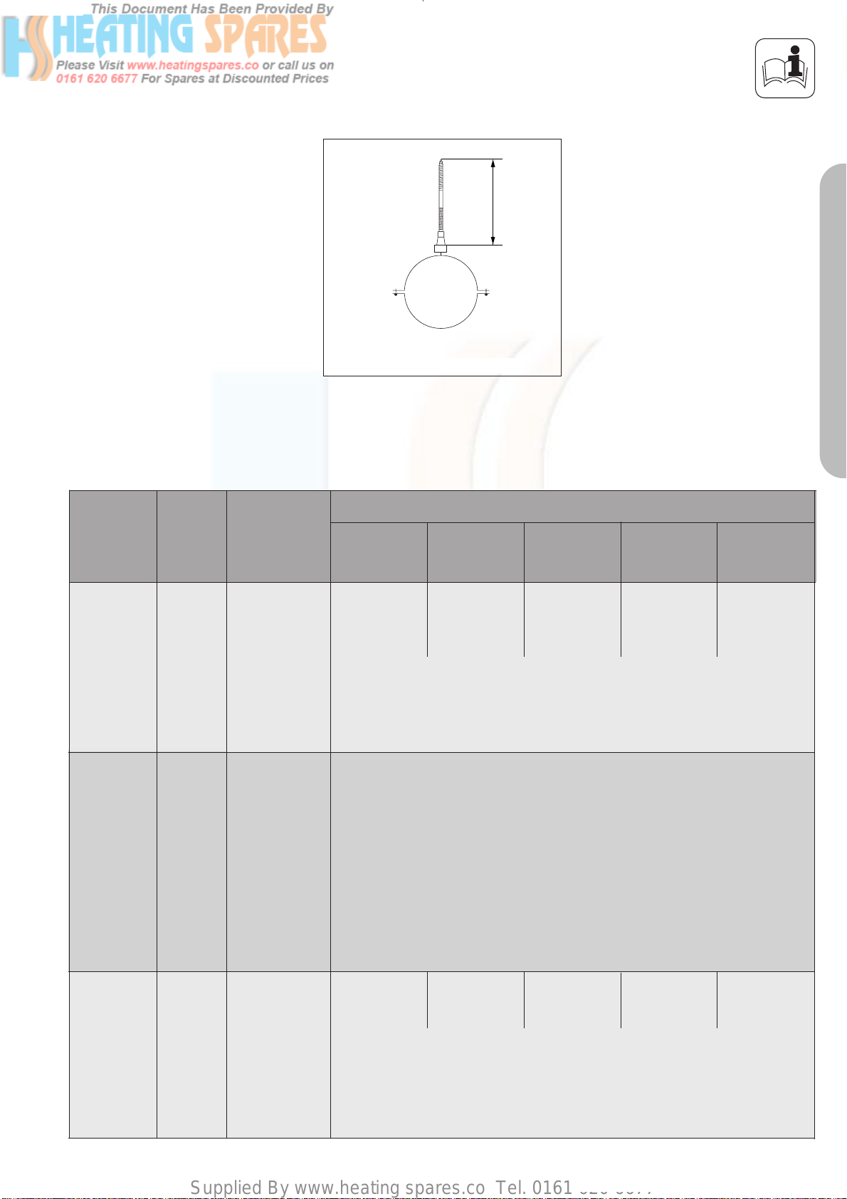
Supplied By www.heating spares.co Tel. 0161 620 6677
60
PLANNING THE AIR/FLUE DUCT LAYOUT
Fig. 1.17: Flue support clip, Ø 60 mm
Flue support clip, Ø 60 mm
delivered with kits
Maximum flue lengths for use with ecoMAX
Accessories Accy. No.
Horizontal
flue systems
Variable
termination
kit
303 933
303 942
303 946
only in
combina-
tion with
303 933
Max. permitted
concentric
flue length
Fig. 1.17
Max. permitted
concentric
flue length
Fig. 1.19
613/2 E
618/2 E
622/2 E
8.0 m
incl.
1 elbow 87°
Maximum length of flue is reduced by 1.0 m for each additional 87° elbow
Maximum length of flue is reduced by 0.5 m for each additional 45° elbow
The maximum permitted concentric flue length given above is reduced as
follows:
- Reduced by 0.5 m for the variable terminal
- Reduced by 0.5 m for every 1 m VTK pipe
- Reduced by 0.5 m for every 87° bend
- Reduced by 0.5 m for 2 x 45° bend
824/2 E
7.0 m
incl.
1 elbow 87°
ecoMAX
828/2 E 635/ E
835/ E
8.0 m
incl.
1 elbow 87°
4.0 m
1 elbow 87°
incl.
PART 1 CONCENTRIC 60/100
pro 18 E
pro 28 E
10.0 m
incl.
1 elbow 87°
Vertical
flue systems
303 900
Max. permitted
concentric
flue length
Fig. 1.18
12.0 m
Maximum length of flue is reduced by 1.0 m for each additional 87° elbow
Maximum length of flue is reduced by 0.5 m for each additional 45° elbow
9.0 m
10.0 m 7.0 m 10.0 m
11
Page 68
Supplied By www.heating spares.co Tel. 0161 620 6677
PLANNING THE AIR/FLUE DUCT LAYOUT
Maximum flue lengths for use with ecoTEC
Accessories Accy. No.
plus 612
plus 615
plus 618
plus 624
plus 824
plus 630
plus 831
ecoTEC
plus 637
plus 837
pro 24
pro 28
plus 415
plus 418
plus 428
plus 438
Horizontal
flue systems
Variable
termination
kit
Vertical
flue systems
303 933 Max. permitted
concentric
flue length
Fig. 1.18
303 942
303 946
only in
combina-
tion with
303 933
303 900
Max. permitted
concentric
flue length
Fig. 1.20
Max. permitted
concentric
flue length
Fig. 1.19
8.0 m
incl.
1 elbow
87°
Maximum length of flue is reduced by 1.0 m for each additional 87° elbow
Maximum length of flue is reduced by 0.5 m for each additional 45° elbow
The maximum permitted concentric flue length given above is reduced as
follows:
- Reduced by 0.5 m for the variable terminal
- Reduced by 0.5 m for every 1 m VTK pipe
- Reduced by 0.5 m for every 87° bend
- Reduced by 0.5 m for 2 x 45° bend
The flue length ouside shall not exceed 10 m.
12.0 m 12.0 m 12.0 m 8.0 m 12.0 m
Maximum length of flue is reduced by 1.0 m for each additional 87° elbow
8.0 m
incl.
1 elbow
87°
8.0 m
incl.
1 elbow
87°
5.5 m
incl.
1 elbow
87°
8.0 m
incl.
1 elbow
87°
10.0 m
incl.
1 elbow
87°
10.0 m
12
Maximum length of flue is reduced by 0.5 m for each additional 45° elbow
Page 69
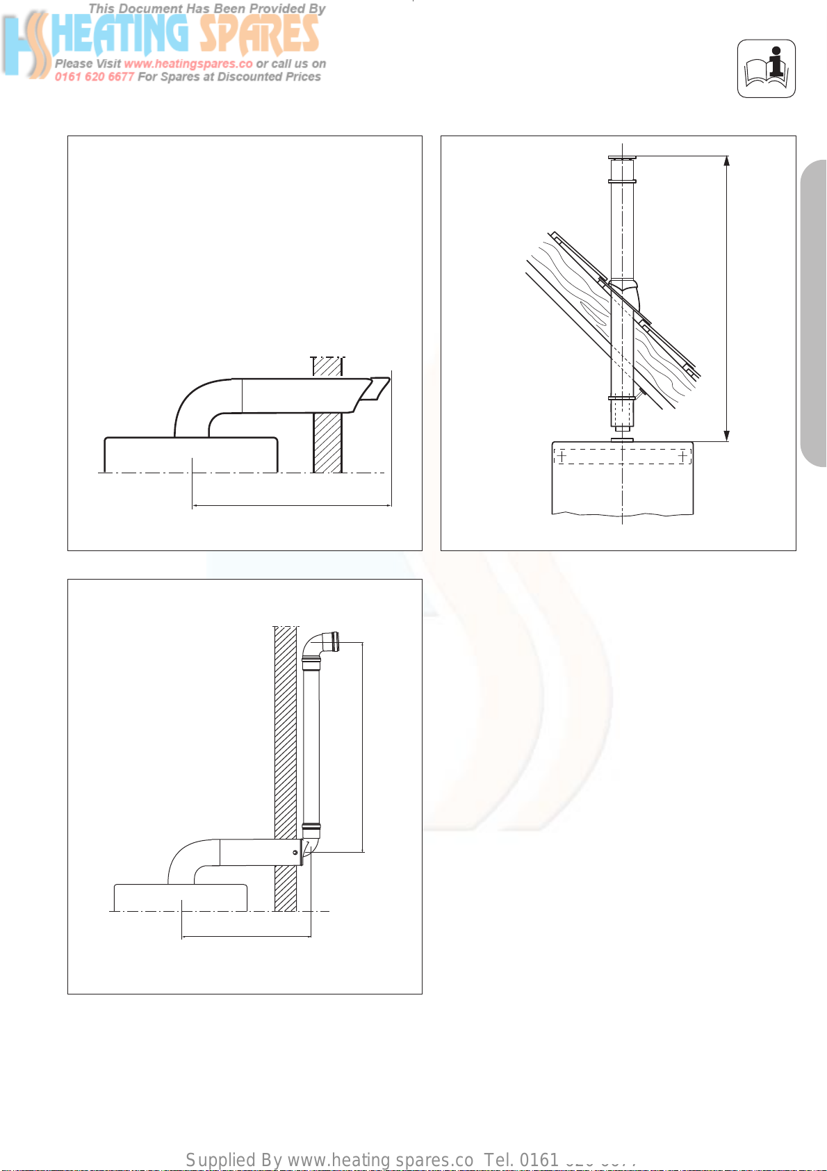
Supplied By www.heating spares.co Tel. 0161 620 6677
PLANNING THE AIR/FLUE DUCT LAYOUT
Maximum flue length
PART 1 CONCENTRIC 60/100
Fig. 1.18: Horizontal flue systems
Maximum flue length
LAS Euro B/S 074/0
Flue length outside
Fig. 1.19: Vertical flue systems
LAS Euro B/S 074/0
Concentric flue length
Fig. 1.20: Horizontal flue system installed with vertical termination kit
13
Page 70
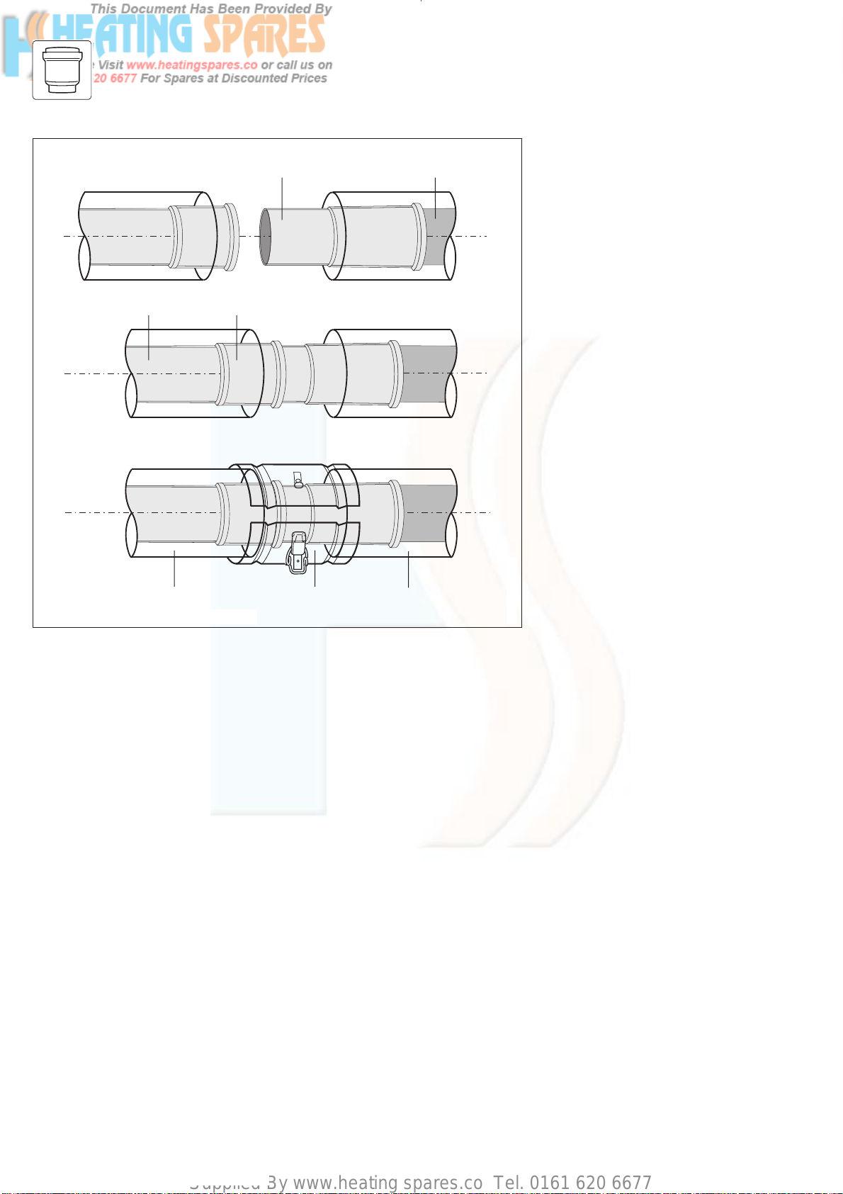
Supplied By www.heating spares.co Tel. 0161 620 6677
INSTALLING THE AIR/FLUE DUCT SLIDING SLEEVE
1
34
6
7
5
2
Fig. 2.0: Installing the sliding sleeve
INSTALLING THE
AIR/FLUE DUCT SLIDING
SLEEVE
☞ NOTE:
For installations where there is insufficient movement to allow fitting
of the flue into flue outlet, a sliding sleeve (Accy. No. 303 915) is
available. When using the sliding
sleeve both the air and flue ducts
of the last extension must be
shortened by a further 95 mm.
• Push the sliding sleeve (1) over the
cut end of the flue duct (2).
• Place the air duct clamp (7) over
the air duct.
• Pull back the sliding sleeve so that
it engages into the socket (3) of
the boiler (4). Ensure that the
sliding sleeve penetrates the
socket such that there is at least
20 mm engagement at both ends
of the sliding sleeve.
• Fit the air duct clamp over the air
Schiebemuffe_neu
ducts (5 and 6) of the
extension/terminal and boiler
outlet. Close the snap clamp.
• Drill two holes 3 mm diameter
through the air duct clamp (the
centre of the holes should be 6
mm from the edge of the clamp).
Ensure that the drill does not
penetrate the inner flue duct.
Screw the air duct clamp to the
air duct of the sleeve using the
screws provided.
• Complete the installation of the
flue as detailed in these
instructions.
14
Page 71
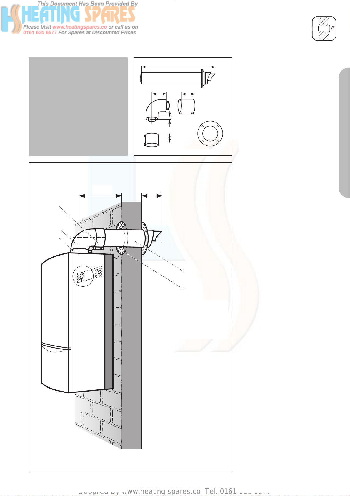
Supplied By www.heating spares.co Tel. 0161 620 6677
INSTALLATION OF THE HORIZONTAL AIR/FLUE DUCT
IMPORTANT:
The air/flue duct is not concentric
and the air duct has a slope of 1.5°
(if the air flue duct is not cut). The
hole through the wall can therefore
be drilled horizontally with no slope.
Where extensions are used, these
must be installed with a slope at 3° ±
1° (equivalent to 50 mm ± 20 mm
rise per metre length) to ensure that
condensate dows not remain in the
sleeve.
*
*87
5
3
4
754
65
Fig. 3.7: Horizontal air/flue conduit
13
30
48
1
Horizontal air/flue duct
Accy No.: 303 933
(Length 0.75 m)
Contents of the accessory:
• Horizontal air/flue duct
• 87° elbow
• 1 x 48 mm air duct clamp
• 1 x 30 mm air duct clamp
• Internal trim ring Ø 100
• External wall seal.
Preparation
• Determine the installation site for
the boiler with reference to the
installation and servicing
instructions supplied with the
boiler.
• Ensure that all installation and
service clearances are available
and that the boiler flue can be
installed as detailed in these
instructions.
• Fix the paper template, supplied
with the boiler, to the wall
ensuring that the centreline of the
template is vertical using a
plumbline or spirit level.
PART 1 CONCENTRIC 60/100
Fig. 3.8
2
* = 190 mm ecoMAX
combination and system boilers
* = 176 mm ecoMAX pro and ecoTEC plus
open vent
* = 125 mm ecoTEC plus
system & combination
Top outlet flue exiting to rear
• For installations where the air/flue
duct is to be installed directly to
the rear of the boiler, the
installation template details the
position of the flue exit hole for
horizontal top outlet installation.
Top outlet flue exiting to side
• For installations where the air/flue
duct is to be installed to the side,
the position of the flue exit hole
can be determined by carefully
levelling across the wall from the
centre line of the air/flue duct hole
marked on the template (fig. 3.9).
• The position of the flue exit hole
should allow the flue to be
installed with a slight upward
slope of about 3° ± 1° (equivalent
to 50 mm ± 20 mm per metre of
flue duct). Calculate the required
rise according to the flue length
and mark the position of the flue
LAS Euro B/S 072/0GB
exit hole.
15
Page 72
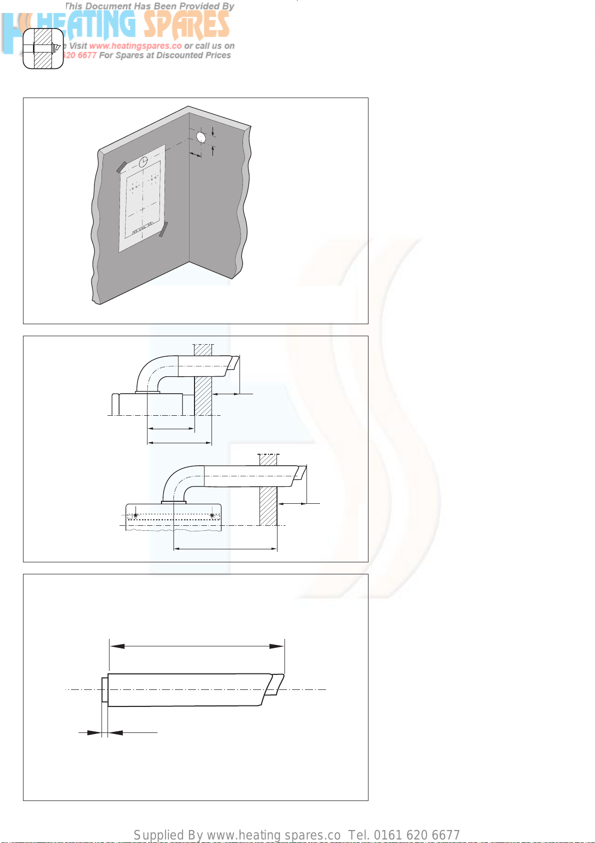
Supplied By www.heating spares.co Tel. 0161 620 6677
INSTALLATION OF THE HORIZONTAL AIR/FLUE DUCT (TOP OUTLET)
Fig. 3.9
Rear exit
* = 190 mm ecoMAX
combination and system boilers
* = 176 mm ecoMAX pro and ecoTEC plus
open vent
* = 125 mm ecoTEC plus
system & combination
Side exit
Fig. 3.10
*
* = 190 mm ecoMAX combination and system boilers
* = 176 mm ecoMAX pro and ecoTEC plus open vent
* = 125 mm ecoTEC plus system & combination
87
*
A
87
A
A + 22 mm
• Once the position of the flue exit
hole has been determined, the
hole should be cut through the
wall using a core drill of 125 mm
diameter.
Note: If access can be gained to
the proposed flue exit point from
outside the dwelling, the hole can
be cut with a 107 mm core drill
and the flue external wall seal
fitted from outside the dwelling.
• Measure the distance from the
outside face of the wall to the
centre of the fan outlet on the
boiler (fig. 3.10).
This is dimension A.
• Cut the air duct and flue duct to
LAS Euro B/S 077/1
the lengths shown in (fig. 3.11).
• All flue sockets should point
towards the terminal.
• When cutting the air and flue
ducts it is important to remove any
burrs with a file, this ensures easy
fitting of the ducts and prevents
any rough edges from damaging
the flue seals.
Care should be taken not to
scratch the white surface of the air
duct.
• If the installation requires the use
of air/flue duct extensions,
additional bends or elbows refer
to the sections on pages 31 - 35.
• Secure the air duct sections
together by drilling a 3 mm
LAS Euro B/S 078/0
diameter hole through the location
hole in the end of the outer air
duct. (Ensure that the drill does
not pierce the inner flue duct).
Secure the air ducts together using
the screw provided.
13 mm
Fig. 3.11
16
LAS Euro B/S 076/0
Page 73
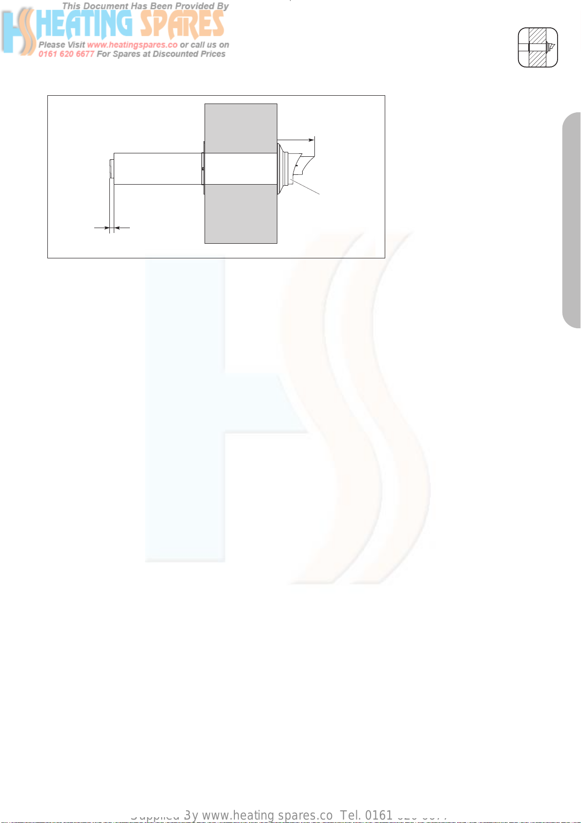
Supplied By www.heating spares.co Tel. 0161 620 6677
Fig. 3.12
INSTALLATION OF THE HORIZONTAL AIR/FLUE DUCT (TOP OUTLET)
• Push the air/flue duct assembly
(1) including the flexible external
87
1
13
LAS Euro B/S 001/0GB
seal through the wall until the
seal clears the outside face of the
wall and pull air/flue duct back
towards the boiler until the
external seal touches the outside
wall (fig. 3.8 and fig 3.12).
• Ensure that the air/flue duct (1) is
centred in the hole and the
terminal is correctly positioned
with the inlet grille at the bottom
(fig 3.8 and fig 3.12).
• Slide the internal trim ring (2) over
the air duct until it is flush with the
wall (fig. 3.8).
• At this stage it is necessary to
prepare and fit the boiler onto the
hanging bracket – refer to the
boiler installation instructions.
• Fit the elbow (3) to the boiler by
inserting the spigot of the flue
elbow into the flue socket on the
boiler and secure using the 30
mm air duct clamp (4) provided
(fig. 3.8).
• Pull the air/flue duct back through
the wall such that the flue duct
fully engages into the flue elbow
socket.
• Fit the 48 mm air duct clamp (5)
ensuring that it is positioned
centrally (fig. 3.8).
• Drill two holes 3 mm Ø through
the air duct of both the elbow/flue
and elbow/boiler clamps at the
most convienient holes on the air
duct clamps. (Ensure that the drill
does not penetrate the inner flue
duct). Screw the clamps to the air
ducts of the flue assembly, the
elbow and boiler using the
screws supplied.
• Slide the internal trim ring back to
the wall, securing in position with
a small amount of sealant if
required.
PART 1 CONCENTRIC 60/100
Caution!
If installed near a light, insects may
fly into the opening. Tell the
homeowner to clean the opening
regularly.
17
Page 74

Supplied By www.heating spares.co Tel. 0161 620 6677
INSTALLATION OF THE TELESCOPIC HORIZONTAL AIR/FLUE DUCT
IMPORTANT:
The air/flue duct is not concentric
and the air duct has a slope of 1.5°
(if the air flue duct is not cut). The
hole through the wall can therefore
be drilled horizontally with no slope.
Where extensions are used, these
must be installed with a slope at 3° ±
1° (equivalent to 50 mm ± 20 mm
rise per metre length) to ensure that
condensate dows not remain in the
sleeve.
*
*87
5
3
4
405 - 610
48
13
30
65
Fig. 3.13: Horizontal air/flue conduit
1
Horizontal telescopic air/flue duct
Accy No.: 303 936
(Length 0.4 - 0.61 m)
Contents of the accessory:
• Horizontal telescopic air/flue duct
• 87° elbow
• 1 x 48 mm air duct clamp
• 1 x 30 mm air duct clamp
• Internal trim ring Ø 100
• External wall seal.
LAS Euro B/S 037/0
Preparation
• Determine the installation site for
the boiler with reference to the
installation and servicing
instructions supplied with the
boiler.
• Ensure that all installation and
service clearances are available
and that the boiler flue can be
installed as detailed in these
instructions.
• Fix the paper template, supplied
with the boiler, to the wall
ensuring that the centreline of the
template is vertical using a
plumbline or spirit level.
Fig. 3.14
2
* = 190 mm ecoMAX
combination and system boilers
* = 176 mm ecoMAX pro and ecoTEC plus
open vent
* = 125 mm ecoTEC plus
system & combination
Top outlet flue exiting to rear
• For installations where the air/flue
duct is to be installed directly to
the rear of the boiler, the
installation template details the
position of the flue exit hole for
horizontal top outlet installation.
Top outlet flue exiting to side
• For installations where the air/flue
duct is to be installed to the side,
the position of the flue exit hole
can be determined by carefully
levelling across the wall from the
centre line of the air/flue duct hole
marked on the template (fig. 3.15).
• The position of the flue exit hole
should allow the flue to be
installed with a slight upward
slope of about 3° ± 1° (equivalent
to 50 mm ± 20 mm per metre of
flue duct). Calculate the required
rise according to the flue length
and mark the position of the flue
LAS Euro B/S 072/0GB
exit hole.
18
Page 75

Supplied By www.heating spares.co Tel. 0161 620 6677
INSTALLATION OF THE TELESCOPIC HORIZONTAL AIR/FLUE DUCT
1
2
A + 22 mm
Fig. 3.15
Rear exit
* = 190 mm ecoMAX
combination and system boilers
* = 176 mm ecoMAX pro and ecoTEC plus
open vent
* = 125 mm ecoTEC plus
system & combination
Side exit
Fig. 3.16
*
* = 190 mm ecoMAX combination and system boilers
* = 176 mm ecoMAX pro and ecoTEC plus open vent
* = 125 mm ecoTEC plus system & combination
87
*
A
A
87
(TOP OUTLET)
• Once the position of the flue exit
hole has been determined, the
hole should be cut through the
wall using a core drill of 125 mm
diameter.
Note: If access can be gained to
the proposed flue exit point from
outside the dwelling, the hole can
be cut with a 107 mm core drill
and the flue external wall seal
fitted from outside the dwelling.
• Measure the distance from the
outside face of the wall to the
centre of the fan outlet on the
boiler (fig. 3.16).
This is dimension A.
• Adjust the air duct and flue duct
LAS Euro B/S 077/1
LAS Euro B/S 078/0
to the lengths shown in (fig.
3.17).
• Secure the air duct sections
together by drilling a 3 mm
diameter hole through the location
hole in the end of the outer air
duct (1). (Ensure that the drill does
not pierce the inner flue duct).
Secure the air ducts together using
the screw (1) provided. Place the
adhesive tape (2) across the gap
in the telescopic extensions.
(fig. 3.17)
• All flue sockets should point
towards the terminal.
• Care should be taken not to
scratch the white surface of the air
duct.
• If the installation requires the use
of air/flue duct extensions,
additional bends or elbows refer
to the sections on pages 31 - 35.
PART 1 CONCENTRIC 60/100
Fig. 3.17
19
Page 76

Supplied By www.heating spares.co Tel. 0161 620 6677
Fig. 3.18
INSTALLATION OF THE TELESCOPIC HORIZONTAL AIR/FLUE DUCT
(TOP OUTLET)
• Push the air/flue duct assembly
(1) including the flexible external
87
1
13
LAS Euro B/S 001/0GB
seal through the wall until the
seal clears the outside face of the
wall and pull air/flue duct back
towards the boiler until the
external seal touches the outside
wall (fig. 3.14 and fig. 3.18).
• Ensure that the air/flue duct (1) is
centred in the hole and the
terminal is correctly positioned
with the inlet grille at the bottom
(fig. 3.14 and fig. 3.18).
• Slide the internal trim ring (2) over
the air duct until it is flush with the
wall (fig. 3.14).
• At this stage it is necessary to
prepare and fit the boiler onto the
hanging bracket – refer to the
boiler installation instructions.
• Fit the elbow (3) to the boiler by
inserting the spigot of the flue
elbow into the flue socket on the
boiler and secure using the 30
mm air duct clamp (4) provided
(fig. 3.14).
• Pull the air/flue duct back through
the wall such that the flue duct
fully engages into the flue elbow
socket.
• Fit the 48 mm air duct clamp (5)
ensuring that it is positioned
centrally (fig. 3.14).
• Drill two holes 3 mm Ø through
the air duct of both the elbow/flue
and elbow/boiler clamps at the
most convienient holes on the air
duct clamps. (Ensure that the drill
does not penetrate the inner flue
duct). Screw the clamps to the air
ducts of the flue assembly, the
elbow and boiler using the
screws supplied.
• Slide the internal trim ring back to
the wall, securing in position with
a small amount of sealant if
required.
20
Caution!
If installed near a light, insects may
fly into the opening. Tell the
homeowner to clean the opening
regularly.
Page 77

Supplied By www.heating spares.co Tel. 0161 620 6677
INSTALLATION OF THE BLACK TERMINAL KIT
Black terminal kit
Accy. No.: 303 934
Contents of the accessory:
• Black terminal
• External wall seal
Fig. 3.19: Black kit
Assembly
Fig. 3.20: Releasing the catches
Fig. 3.21: Pulling out the terminal
Before installing the flue
duct
• Use an 8 mm screwdriver to bend
the catches inwards (fig. 3.20).
• Pull the terminal together with the
flue duct out of the air duct (fig.
3.21).
• Unlock the catch between the
terminal and the flue duct by
twisting them against each other
(fig. 3.22).
• Pull the terminal off the flue duct.
• Push the new terminal into the flue
duct and click to lock.
☞ Please note: The catch on the top
of the terminal must lock firmly
into the notch in the flue duct
(fig. 3.23).
☞ Please note: Make sure the seal
fits tightly.
• Push the flue duct and the terminal
back into the air duct and lock the
two catches (fig. 3.24).
PART 1 CONCENTRIC 60/100
Fig. 3.22: Unlocking the catch
Caution!
The seam of the air duct must be at
the top.
• Fit the horizontal air/flue duct as
described on pages 15 and 18.
21
Page 78

Supplied By www.heating spares.co Tel. 0161 620 6677
INSTALLATION OF THE BLACK TERMINAL KIT
Fig. 3.23: Flue duct
Fig. 3.24: Locking the catch
Assembly
After installing the flue
duct
Danger!
Before starting work, shut down the
appliance and prevent it from being
switched on unintentionally.
• Remove the wall seal from the
terminal.
• Use an 8 mm screwdriver to bend
the catches inwards (fig. 3.20).
• Pull the terminal together with the
flue duct out of the air duct (fig.
3.21).
Caution!
Do not twist the flue duct, because
this might detach the following flue
duct behind the terminal from the
spacer.
• Unlock the catch between the
terminal and the flue duct by
twisting them against each other
(fig. 3.22).
• Pull the terminal off the flue duct.
• Push the new terminal into the flue
duct and click to lock.
☞ Please note: The catch on the top
of the terminal must lock firmly
into the notch in the flue duct (fig.
3.23).
☞ Please note: Make sure the seal
fits tightly.
• Push the flue duct with the
terminal back in the air duct.
Carefully push the flue duct back
into the sleeve of the pipe or bend
behind it. Lock the two catches
(fig. 3.24).
• Fit the wall seal.
Danger!
Before starting up the appliance,
check that the entire flue pipe is
firmly seated and sealed.
22
Page 79

Supplied By www.heating spares.co Tel. 0161 620 6677
INSTALLATION OF THE VARIABLE TERMINATION KIT
55
Important:
The flue outlet of the variable termination must face directly upwards.
Flue Terminal Clearances
Minimum flue terminal clearances
are defined in BS5440, and these
must apply unless the boiler manufacturer has received approval to
quote smaller clearances that are
not safety critical. Vaillant have reduced flue terminal clearances
approved and these are given in the
boiler installation instructions. These
are the minimum clearances that
must apply to all installations, except
when a Variable Termination Kit
(VTK) is fitted.
When a VTK is fitted to the horizontal flue, the terminal clearances for
the air inlet are reduced. The terminal clearances for the ‘new’ flue
outlet at the end of the VTK do not
change.
Variable termination kit
Accy. No.:
303 942 (black)
303 946 (white)
Contents of the kit:
• Variable terminal
• 2 x 1m pipe
• 3 x pipe support clips
• 87° bend with bird protection
grille
Fig. 4.1: Variable termination kit
PART 1 CONCENTRIC 60/100
The minimum terminal clearances A,
B & C for the air inlet of the VTK are
reduced to 50 mm from an opening
such as a window, and 25mm from
an opening such as an airbrick. This
means that the terminal on the
horizontal flue becomes the air inlet
when a VTK is fitted, and hence can
be located less than 300mm from
an opening window or airbrick.
Fig. 4.2
Assembly
Before installing the flue
pipe
• Use an 8 mm screwdriver to bend
the catches inwards (fig. 4.3).
• Pull the terminal with the flue duct
out of the air duct (fig. 4.4).
Fig. 4.3: Releasing the catch
Fig. 4.4: Pulling out the variable terminal
23
Page 80
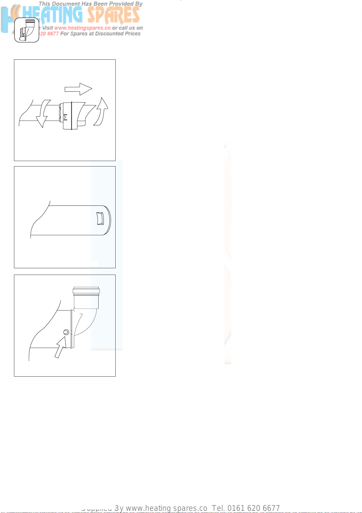
Supplied By www.heating spares.co Tel. 0161 620 6677
INSTALLATION OF THE VARIABLE TERMINATION KIT
Fig. 4.5: Unlocking the catch
Fig. 4.6: Flue pipe
Fig. 4.7: Locking the catch
• Unlock the catch between the
terminal and the flue duct by
twisting them against each other
(fig. 4.5).
• Pull the terminal out of the flue
duct.
• Push the variable terminal onto the
flue duct.
☞ Please note: The catch on the top
of the variable terminal must lock
firmly into the notch in the flue
duct (fig. 4.6).
Caution!
Make sure the seal fits tightly.
• Push the flue duct and the variable
terminal back into the air duct
and lock the two catches
(fig. 4.7).
☞ Please note: The seam of the air
duct must be at the top.
• Fit the horizontal ait/flue duct as
described on pages 15 and 18.
Caution!
It cannot be fitted from inside.
• Fit the rest of the variable
termination kit as described on
page 25.
Assembly
After installing the flue
duct
Danger!
Before starting work, shut down the
appliance and prevent it from being
switched on unintentionally.
• Remove the wall seal from the
terminal.
• Use an 8 mm screwdriver to bend
the catches inwards (fig. 4.3).
• Pull the terminal with the flue duct
out of the air duct (fig. 4.4).
Caution!
Do not twist the flue duct, because
this might detach the following flue
duct behind the terminal from the
spacer.
• Unlock the catch between the
terminal and the flue duct by
twisting them against each other
(fig. 4.5).
• Pull the terminal out of the flue
duct.
• Push the new variable terminal
onto the flue duct.
☞ Please note: The catch on the top
of the variable terminal must lock
firmly into the notch in the flue
duct (fig. 4.6).
☞ Please note: Make sure the seal
fits tightly.
• Push the flue duct with the
variable terminal back in the air
duct. Carefully push the flue duct
back into the sleeve of the duct or
bend behind it. Lock the two
catches (fig. 4.7).
• Fit the wall seal on the variable
terminal.
• Fit the rest of the VTK as
described on page 25.
24
Page 81
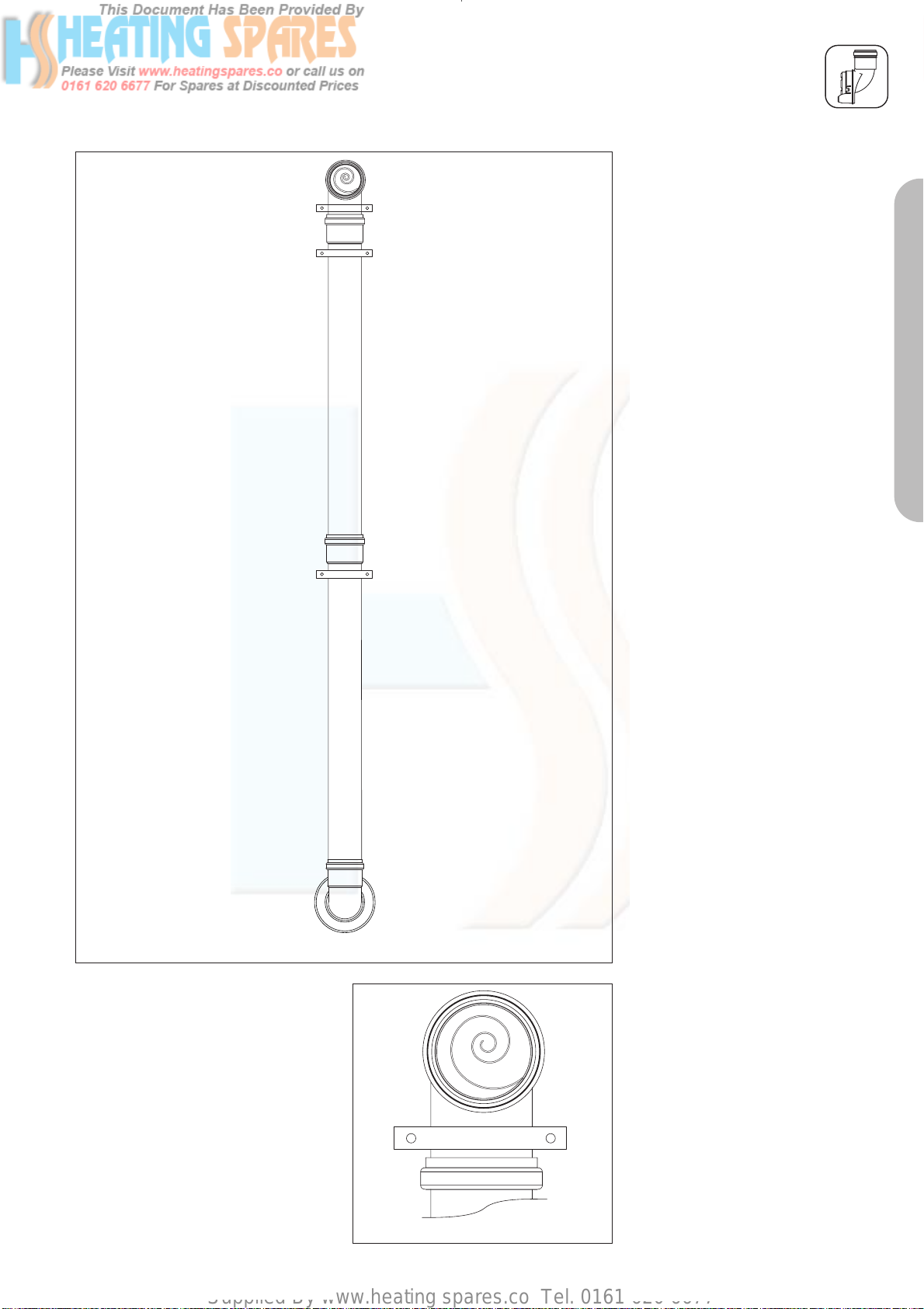
Supplied By www.heating spares.co Tel. 0161 620 6677
INSTALLATION OF THE VARIABLE TERMINATION KIT
• Fit the pipes and bends, working
from the variable terminal to the
selected location for the flue exit
using support clips supplied fig
4.8, 4.9, 4.10 or 4.11.
Caution!
Pipe extensions must be fixed to the
wall using pipe clamps. Use one
clamp for each extension directly
beside the sleeve. Fit another clamp
to the extension after each 87° bend
(fig. 4.9).
Caution!
The extension pipe expands when
heated.
Leave 1 cm expansion space in each
sleeve.
☞ Please note: The maximum flue
lengths where the variable
termination kit is installed are
shown in the tables on pages 11
and 12.
☞ Please note: The parts are simply
pushed together (not bolted).
PART 1 CONCENTRIC 60/100
Fig. 4.8: Installation of basic kit showing position of support clips
Caution!
Fasten the 87° bend with bird
protection grille using a separate
pipe clamp (fig. 4.9).
Caution!
If installed near a light, insects may
fly into the opening. Tell the
homeowner to clean the opening
regularly.
Danger!
Before starting up the appliance,
check that the entire flue pipe is
firmly seated and sealed.
Caution!
During annual maintenance, check
the flue system for
- visible defects, such as
embrittlement or damage
- tight connection of the pipes
- dirt in the air intake and flue exits
due to leaves, insects etc.
Fig. 4.9: Bird protection grille
25
Page 82
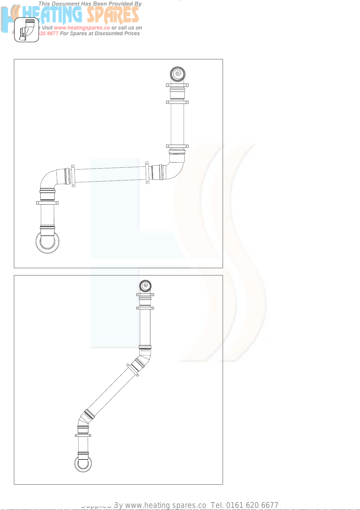
Supplied By www.heating spares.co Tel. 0161 620 6677
INSTALLATION OF THE VARIABLE TERMINATION KIT
Fig. 4.10: Installation of basic kit with two additional 87° bends showing position of support clips
Fig. 4.11: Installation of basic kit with two additional 45° bends showing position of support clips
26
Page 83
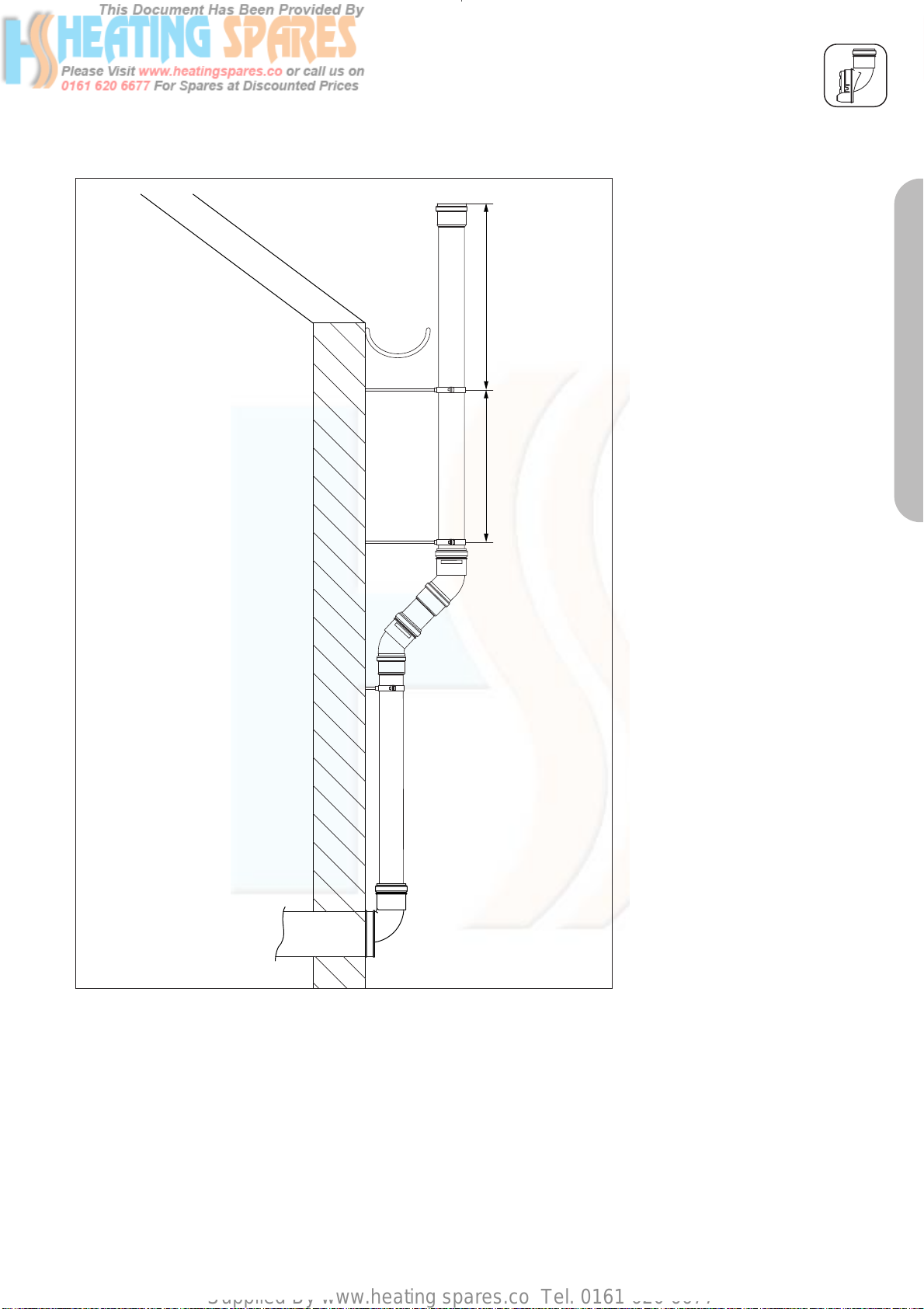
Supplied By www.heating spares.co Tel. 0161 620 6677
min 400 mm min 100 mm
INSTALLATION OF THE VARIABLE TERMINATION KIT
Routing around roof
eaves
When routing the variable
termination kit around the roof eaves,
additional lengths of M8 threaded
bar will be required for the support
brackets. Threaded bar can be
purchased from most local merchants.
• Change the bird protection grille
from the 87° elbow to the
extension installed at the end.
☞ If using the 87° elbow, use the
seal from the pipe extension.
• The final pipe extension must be
fixed to the wall using two support
clips with a minimum distance of
400 mm.
PART 1 CONCENTRIC 60/100
Fig. 4.12: Routing around roof eaves
• Additional 45° bends may be
required.
27
Page 84
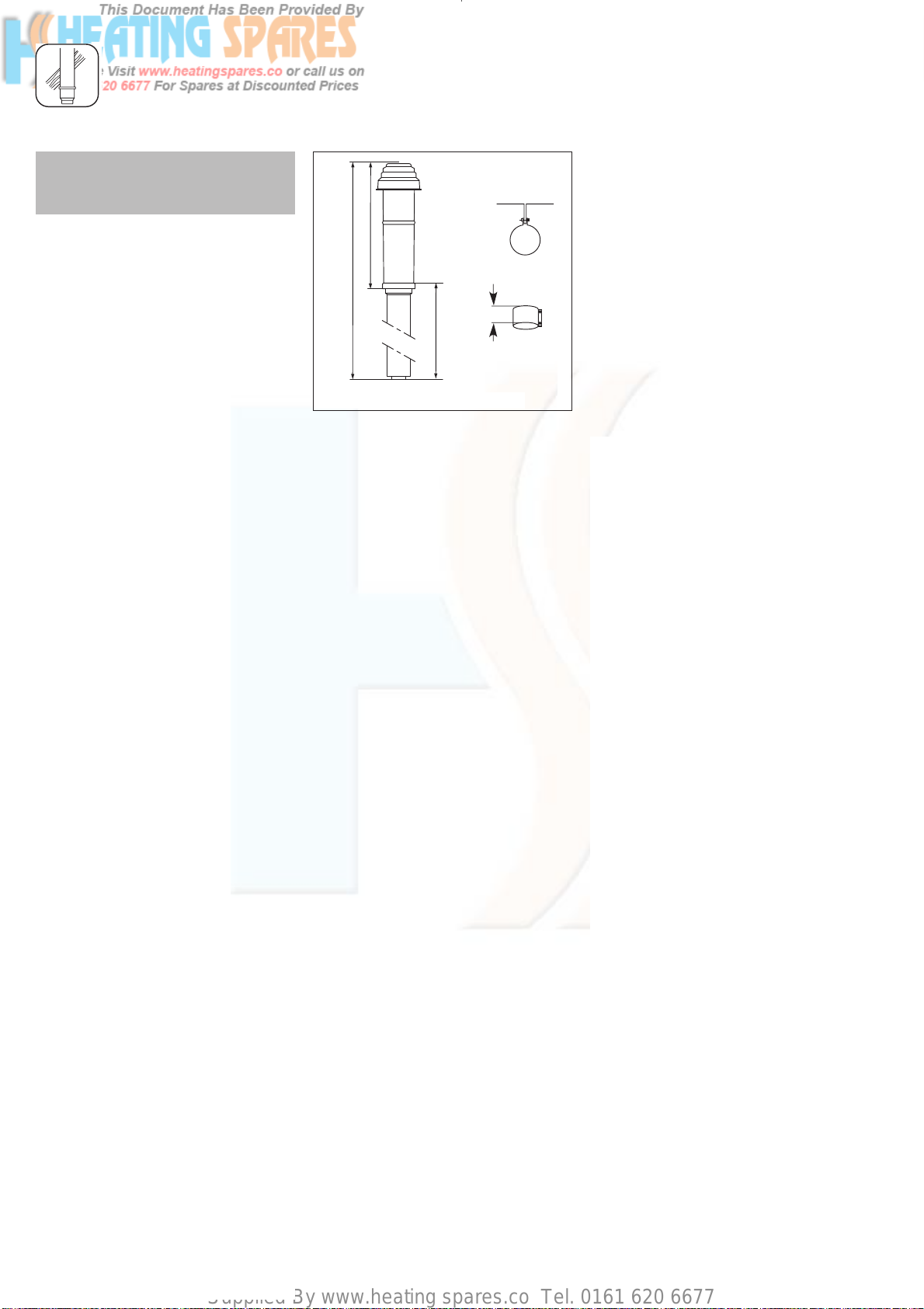
Supplied By www.heating spares.co Tel. 0161 620 6677
INSTALLATION OF THE VERTICAL AIR/FLUE DUCT
☞ Observe the maximum flue
lengths as detailed in table on
page 11.
550
1435
Fig. 5.1: Vertical roof duct
880
40
Vertical air/flue duct
Accy. No.: 303 900 (black)
Contents of the accessory:
• Vertical air/flue duct and terminal
assembly
• 40 mm air duct clamp
• Fixing bracket
☞ See page 6 et seq. for details of
air/flue duct elements.
The air/flue duct assembly may be
connected directly to the flue outlet
on top of the boiler.
In addition to the vertical air/flue
duct and terminal accessory, air/flue
duct extensions can be added to
increase the length of the flue.
Preparation
• Determine the installation site for
the boiler with reference to the
installation and servicing
instructions supplied with the
boiler.
• Ensure that all installation and
service clearances are available
and that the boiler flue can be
installed as detailed in these
instructions.
• Determine the point where the
vertical air/flue duct and terminal
assembly will penetrate the roof.
☞ Please note: The vertical air/flue
duct and terminal accessory
(Accy. No. 303 900) may be
shortened. The outer ‘white’ duct
should be shortened first, then the
inner flue duct cut so that it
protrudes 13 mm out of the air
duct. In case of installation
directly to the boiler without
elbows or bends, it is essential
that the roof tile/collar is vertically
aligned with the air/flue duct of
the boiler.
28
☞ Please note: If a 87° elbow is
connected directly to the boiler,
use the 40 mm air duct clamp
supplied with the vertical air flue
duct at this position.
Page 85
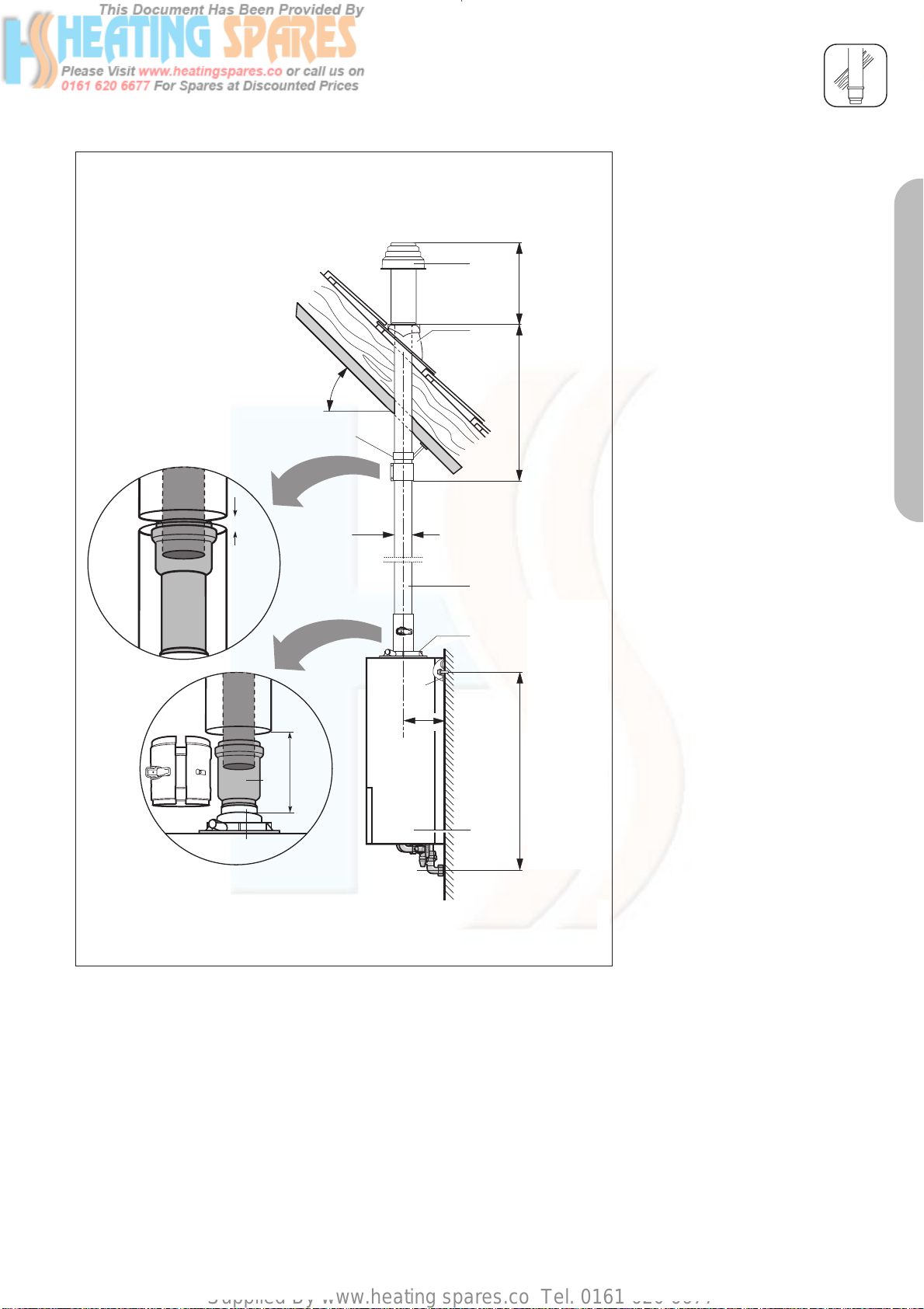
Supplied By www.heating spares.co Tel. 0161 620 6677
INSTALLATION OF THE VERTICAL AIR/FLUE DUCT
5
1
20 – 50
6
100- 110
Ø100
7
8
2
*
3
0 - 5
4
8
* = 190 mm ecoMAX
combination and system boilers
* = 176 mm ecoMAX pro and ecoTEC plus open vent
* = 125 mm ecoTEC plus system & combination
Fig. 5.2: Fitting the appliance and the vertical roof duct to a building with a pitched roof
550
885
750
combination and system boilers
(top holes of bracket)
750 mm ecoMAX
530 mm ecoMAX pro and ecoTEC plus open vent
622 mm ecoTEC plus system & combination
Pitched roof installation
• Determine the point where the
vertical air/flue duct and terminal
assembly will penetrate the roof.
• Fit the flexible pitched roof (Accy.
No. 303 980) tile (1).
• Working from above, insert the
vertical roof duct (5) through the
roofing tile and push it firmly into
place.
• Vertically align the roof duct and
attach it to the roof structure with
the fixing bracket (6) supplied.
• Fit the boiler hanging bracket (2).
• Install the appliance (3) with
reference to the installation and
servicing instructions supplied with
the boiler.
☞ See pages 33 et seq. for further
details on the installation of
extensions and elbows.
• Push the sliding sleeve (4) firmly
into place on the extension.
• Join the vertical roof duct (5) to
the extension (7).
• Join the sliding sleeve (4) to the
appliance’s connection piece (8).
☞ Using the sliding sleeve allows the
appliance to be easily removed
and replaced without dismantling
the flue.
• Drill two holes 3 mm Ø through
the air duct of the flue/boiler
clamp at the most convienient
holes on the air duct clamp.
(Ensure that the drill does not
penetrate the inner flue duct).
Screw the clamp to the air ducts
of the flue assembly and the boiler
using the screws supplied.
• Ensure that any air duct clamps
used are positioned centrally and
fixed to the air duct using the self
tapping screws supplied.
• Note: The air/duct clamp must not
be screwed to the bottom of the
vertical air/flue duct and terminal
accessory to allow for any slight
movement in the roof structure.
• Ensure that at least one pipe
clamp supports the air/flue duct
at each extension fitted.
PART 1 CONCENTRIC 60/100
29
Page 86
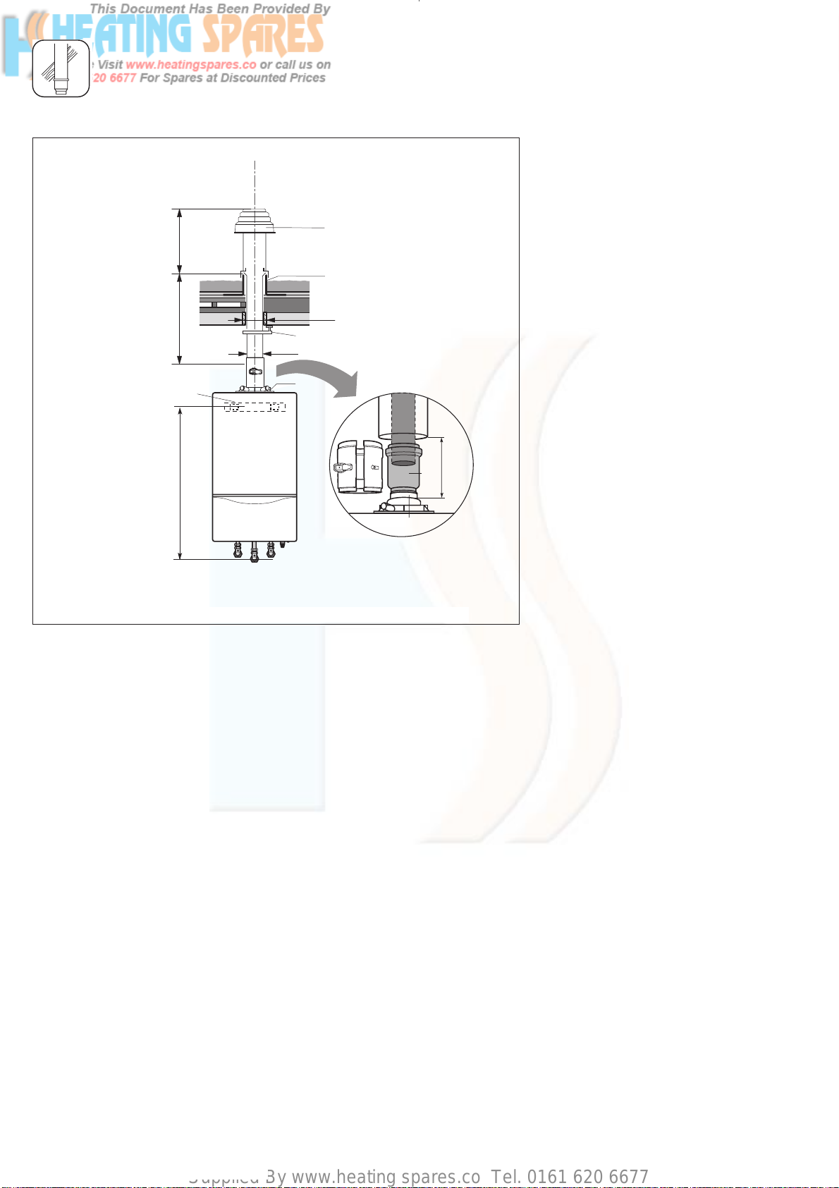
Supplied By www.heating spares.co Tel. 0161 620 6677
INSTALLATION OF THE VERTICAL AIR/FLUE DUCT
5
550
cold roof
885
2
750
combination and system boilers
(top holes of bracket)
750 mm ecoMAX
530 mm ecoMAX pro and ecoTEC plus open vent
622 mm ecoTEC plus system & combination
Fig. 5.3: Fitting the appliance and vertical flue duct to a building with a flat roof
warm roof
6
Ø100
7
1
120
Flat-roof installation
• Determine the point where the
vertical air/flue duct and terminal
assembly will penetrate the roof.
• Fit the flat roof penetration collar
(1).
• Stick the flat roof penetration
collar firmly into place with
adhesive in accordance with the
codes of practice for flat roofs
(CP 144) to ensure a watertight
seal.
• Working from above, insert the
vertical roof duct (5) through the
flat roof collar and push it firmly
into place.
• Vertically align the roof duct and
attach it to the roof structure with
4
100- 110
7
the fixing bracket (6) supplied.
• Fit the boiler hanging bracket (2).
• Install the appliance (3) with
reference to the installation and
servicing instructions supplied with
the boiler.
☞ See pages 31 et seq. for further
details on the installation of
extensions and elbows.
• Push the sliding sleeve (4) firmly
into place on the extension.
• Join the vertical roof duct (5) to
the extension (7).
• Join the sliding sleeve (4) to the
appliance’s connection piece (8).
This permits easy separation
between the air/flue duct and the
appliance.
• Drill two holes 3 mm Ø through
the air duct of the flue/boiler
clamp at the most convienient
holes on the air duct clamp.
(Ensure that the drill does not
penetrate the inner flue duct).
Screw the clamp to the air ducts
of the flue assembly and the boiler
using the screws supplied.
• Ensure that any air duct clamps
used are positioned centrally and
fixed to the air duct using the self
tapping screws supplied.
• Note: The air/duct clamp must not
be screwed to the bottom of the
vertical air/flue duct and terminal
accessory to allow for any slight
movement in the roof structure.
• Ensure that at least one pipe
clamp supports the air/flue duct
at each extension fitted.
30
Page 87
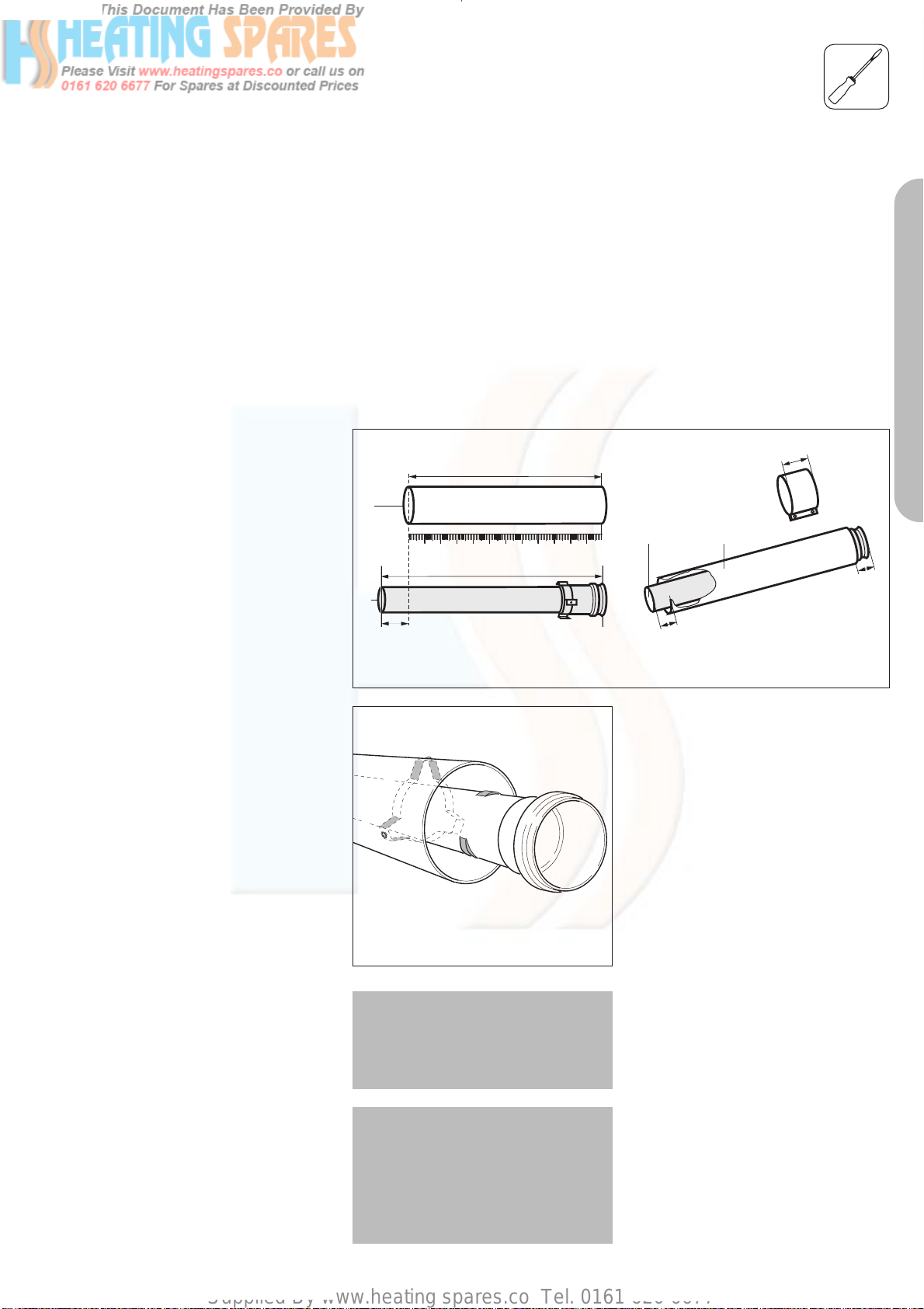
Supplied By www.heating spares.co Tel. 0161 620 6677
How to add extensions
Use a saw, tin-snips, etc. to cut tubes
to size.
☞ No tools are required when
separating extensions for cutting to
size air and flue tubes separately.
When doing so, the flue conduit
should be twisted into a position
where the shoulders on the plastic
tube can be pushed through the
spacer-piece. After cutting to size,
refit the flue conduit and secure it
to the air conduit.
FITTING AIR/FLUE DUCT EXTENSIONS
2
1
+ 40 mm
Fig. 6.1: Cutting tubes to size
L
air
L
exhaust
70
PART 1 CONCENTRIC 60/100
1.
1
2.
13
2
27
Tip:
Start by measuring the required
length of air conduit* (L
), and then
air
calculate the corresponding length of
flue conduit (L
L
exhaust
L
exhaust
L
air
= L
= length of flue conduit
= length of air conduit
exhaust
air
) as follows:
+ 40 mm
* Minimum length of air-conduit
extension: 80 mm.
Fig. 6.2: Loosening the flue conduit
Important:
You must fasten extensions to the
ceiling or wall using pipe clamps.
Use one clamp for each extension.
Important:
Where extensions are used, these
must be installed with a slope of 3°
±1° to ensure that condensate does
not remain in the sleeve (equivalent
to 50 mm ± 20 mm rise per metre
length).
☞ The seals are sensitive to mineral
oil-based grease products. For this
reason, the seals must not be
greased. If the seals need wetting
to aid in installation, use water
only.
☞ De-burr and file down any rough
edges on the tubes before fitting in
order to prevent damage to the
seals. Remove all metal filings and
other debris.
☞ Do not use damaged or dented
tubes, as they will not form an
adequate seal.
☞ Ensure that the seals remain
correctly aligned when installing
the tubes. Do not fit damaged
seals.
☞ Secure the exhaust conduit with
the fixing device in order to ensure
that it is correctly centred relative
to the air conduit.
31
Page 88
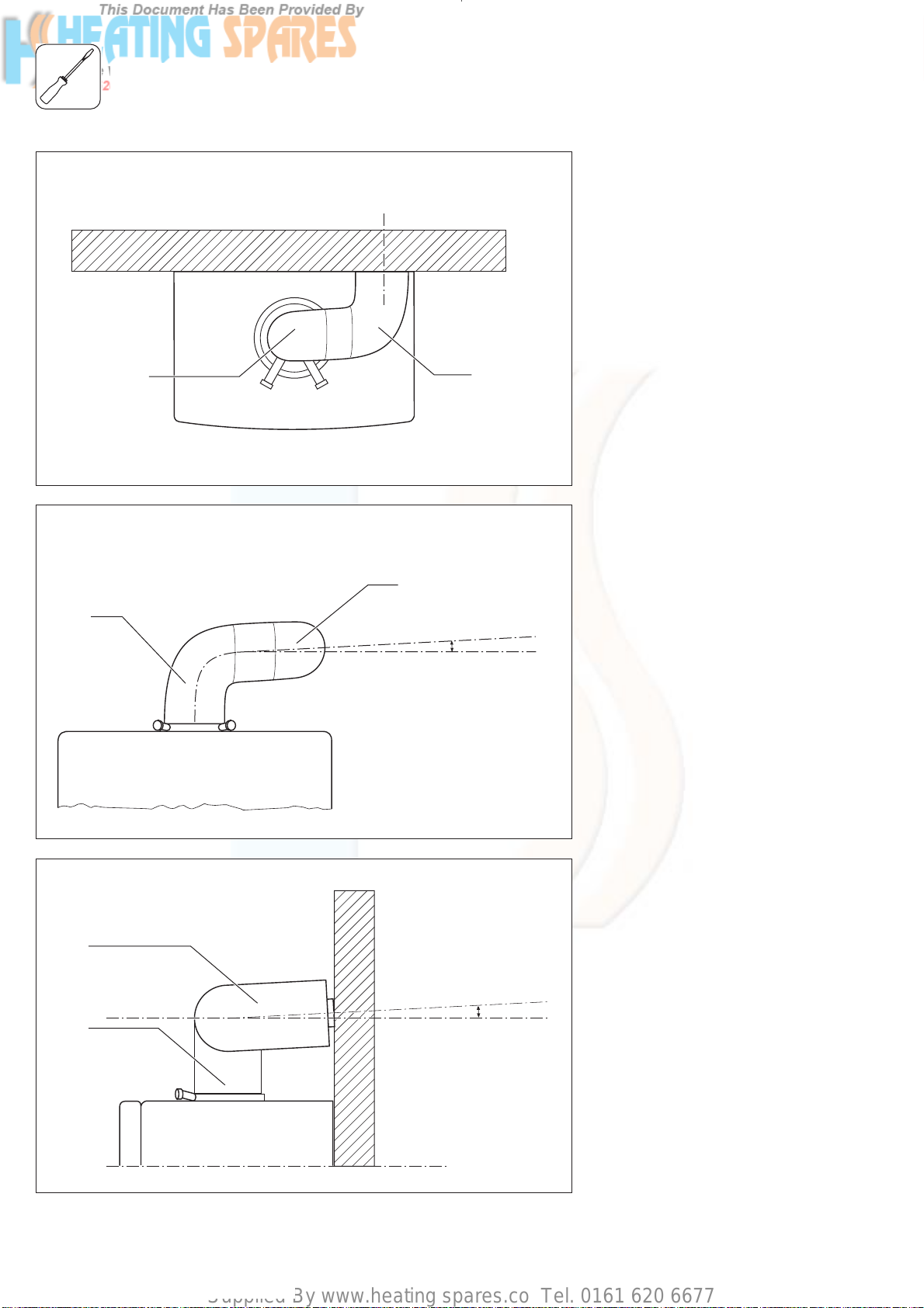
Supplied By www.heating spares.co Tel. 0161 620 6677
FITTING AIR/FLUE DUCT EXTENSIONS
1
2
How to install
2x 87° elbows
• When using 2 x 87° elbows
follow fig. 6.1 to fig. 6.3 to avoid
obstructions on outer wall.
Note: The elbows must be
correctly aligned to avoid undue
stress on the joints and risk of
leakage.
The elbow fitted to the top of the
boiler (1) should be twisted by 3°
to ensure that the second 87° elbow (2) exits the wall perpendicular.
Fig. 6.1: Arrangement of 2 x 87° elbows – View from above
1
Fig. 6.2: Arrangement of 2 x 87° elbows – View from front
2
* = 3
• When using elbows for long flue
runs in a corner follow fig. 6.4
and fig. 6.5 to avoid obtrsuctions.
☞ Note: The elbows must be
correctly aligned to avoid undue
stress on the joints an risk of
leakage.
The elbow fitted to the top of the
*
boiler (1) should be twisted by 3°
to ensure that the second 87° elbow (2) exits the wall perpendicular.
When using 87° elbow install with
a slope of 3° between wall and
air-flue pipe (fig. 6.4) or use 2 x
45° elbows (fig. 6.5).
2
1
Fig. 6.3: Arrangement of 2 x 87° elbows – View from side
32
*
* = 3
Page 89
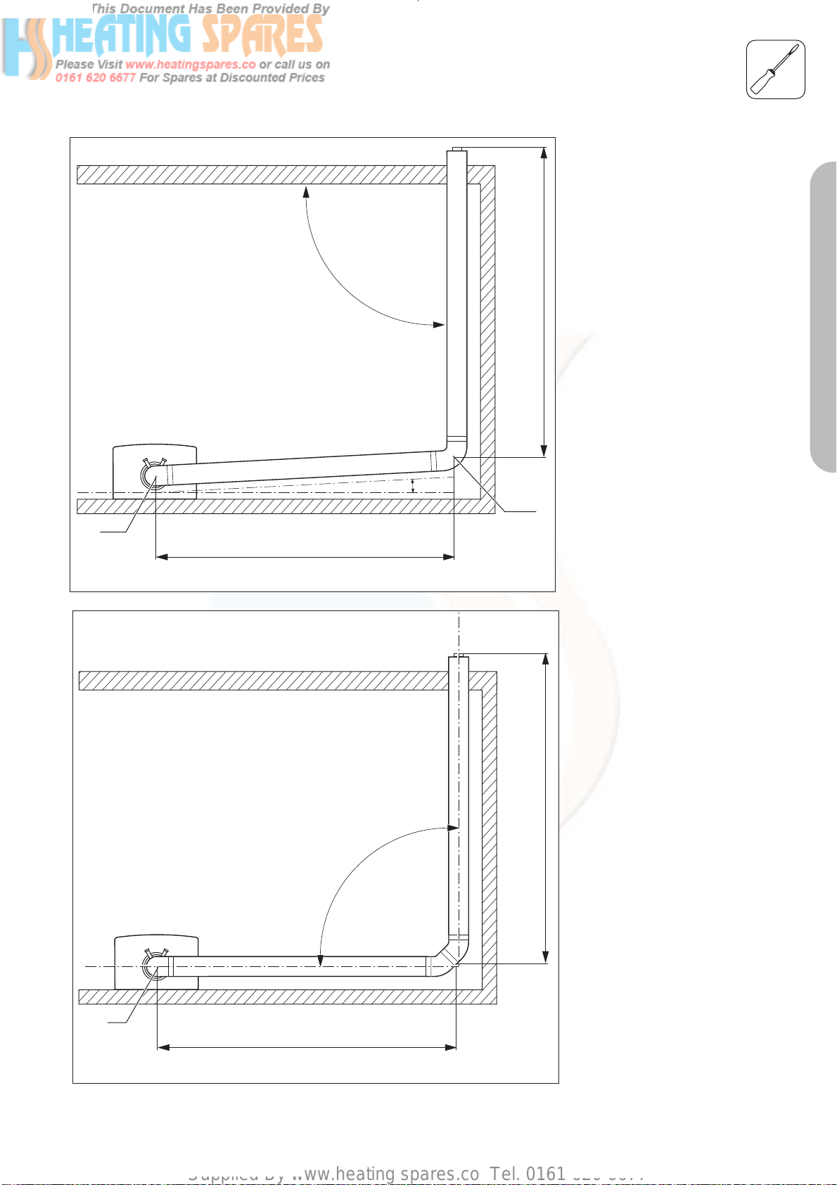
Supplied By www.heating spares.co Tel. 0161 620 6677
90
FITTING AIR/FLUE DUCT EXTENSIONS
• When using elbows for long flue
runs in a corner follow fig. 6.4
and fig. 6.5 to avoid obtrsuctions.
☞ Note: The elbows must be
correctly aligned to avoid undue
stress on the joints an risk of
leakage.
The elbow fitted to the top of the
boiler (1) should be twisted by 3°
to ensure that the second 87° el-
max. 5 m
bow (2) exits the wall perpendicular.
When using 87° elbow install with
a slope of 3° between wall and
air-flue pipe (fig. 6.4) or use 2 x
45° elbows (fig. 6.5).
PART 1 CONCENTRIC 60/100
1
Fig. 6.4: Long flue runs – using 87° elbow
max. 5 m
90
*
2
* = 3
max. 5 m
1
max. 5 m
Fig. 6.5: Long flue elbow – Using 45° elbows
33
Page 90

Supplied By www.heating spares.co Tel. 0161 620 6677
FITTING AIR/FLUE DUCT EXTENSIONS
How to install 87° elbows
Accy. No.: 303 910
☞ Note: The elbow delilvered with
the flue kits 303 933 and
303 936 is not the same
dimension as shown here.
Example:
An offset of 400 mm is measured.
This value is then used, along with the
table below, to determine the length
of the air conduit ( = 190 mm in this
case).
Important:
This gives a corresponding
exhaust-conduit length of
190 + 40 = 230 mm.
Table 6.1: Length of surplus with 87° elbows
Offset Length of
[in mm] air conduit
> 190 to
< 210 mm 0
> 215 to not
< 265 mm possible
> 270 to
< 290 mm 80
295 85
300 90
305 95
310 100
315 105
320 110
325 115
330 120
335 125
340 130
345 135
350 140
355 145
360 150
365 155
370 160
375 165
380 170
385 175
390 180
395 185
400 190
405 195
410 200
415 205
420 210
425 215
430 220
435 225
[in mm
]
Offset
091
Length of air conduit
95
10
Fig. 6.3: Installation of 87° elbows
Offset Length of
[in mm] air conduit
440 230
445 235
450 240
455 245
460 250
465 255
470 260
475 265
480 270
485 275
490 280
495 285
500 290
505 295
510 300
515 305
520 310
525 315
530 320
535 325
540 330
545 335
550 340
555 345
560 350
565 355
570 360
575 365
580 370
585 375
590 380
595 385
600 390
605 395
610 400
615 405
620 410
625 415
[in mm
95
10
GU_LAZ 102/2GB
Offset Length of
[in mm] air conduit
]
630 420
635 425
640 430
645 435
650 440
655 445
660 450
665 455
670 460
675 465
680 470
685 475
690 480
695 485
700 490
705 495
710 500
715 505
720 510
725 515
730 520
735 525
740 530
745 535
750 540
755 545
760 550
765 555
770 560
775 565
780 570
785 575
790 580
795 585
800 590
[in mm
]
34
Page 91
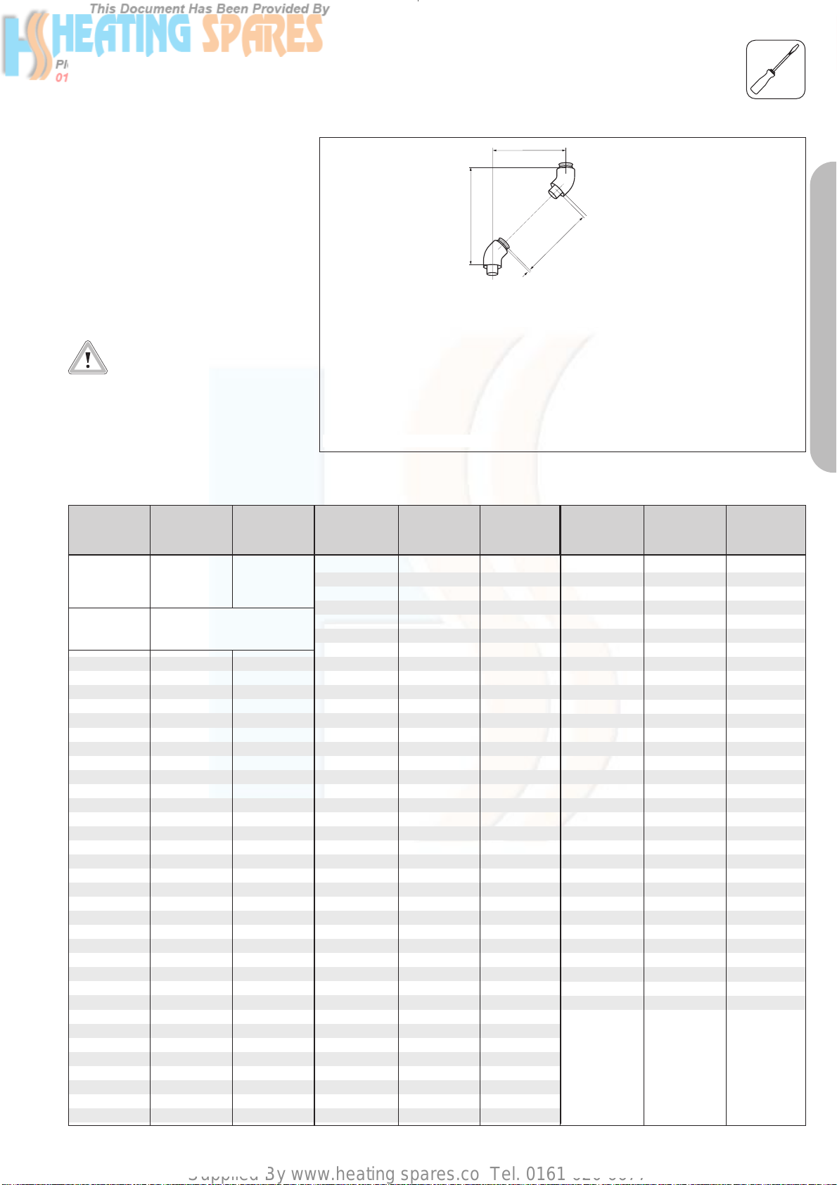
Supplied By www.heating spares.co Tel. 0161 620 6677
FITTING AIR/FLUE DUCT EXTENSIONS
How to install 45° elbows
Accy. No.: 303 911
Example:
An offset of 400 mm is measured.
This value is then used, along with the
table below, to determine the length
of the air conduit (= 284 mm) and the
height (= 420 mm).
Important:
This gives a corresponding
exhaust-conduit length of
284 + 40 = 324 mm.
Table 6.2: Length of surplus with 45° bends
Offset Length of Height
[in mm] air conduit [in mm]
[in mm]
90 0 210
95 0 215
100 0 220
> 105 to not
< 155 mm possible
160 86 280
165 93 285
170 100 290
175 107 295
180 115 300
185 122 305
190 129 310
195 136 315
200 143 320
205 150 325
210 157 330
215 164 335
220 171 340
225 178 345
230 185 350
235 192 355
240 199 360
245 206 365
250 214 370
255 221 375
260 228 380
265 235 385
270 242 390
275 249 395
280 256 400
285 263 405
290 270 410
295 277 415
300 284 420
305 291 425
310 298 430
315 306 435
320 313 440
thgieH
Fig. 6.4: Installation of 45° bends
Offset Length of Height
[in mm] air conduit [in mm]
[in mm]
325 320 445
330 327 450
335 334 455
340 341 460
345 348 465
350 355 470
355 362 475
360 369 480
365 376 485
370 383 490
375 390 495
380 397 500
385 404 505
390 412 510
395 419 515
400 426 520
405 433 525
410 440 530
415 447 535
420 454 540
425 461 545
430 468 550
435 475 555
440 482 560
445 489 565
450 496 570
455 503 575
460 511 580
465 518 585
470 525 590
475 532 595
480 539 600
485 546 605
490 553 610
495 560 615
500 567 620
505 574 625
510 581 630
515 588 635
520 595 640
Offset
01
tiudnoc ria fo htgneL
01
PART 1 CONCENTRIC 60/100
GU_LAZ 103/2GB
Offset Length of Height
[in mm] air conduit [in mm]
525 602 645
530 610 650
535 617 655
540 624 660
545 631 665
550 638 670
555 645 675
560 652 680
565 659 685
570 666 690
575 673 695
580 680 700
585 687 705
590 694 710
595 701 715
600 709 720
605 716 725
610 723 730
615 730 735
620 737 740
625 744 745
630 751 750
635 758 755
640 765 760
645 772 765
650 779 770
655 786 775
660 793 780
665 800 785
670 808 790
675 815 795
680 822 800
[in mm]
35
Page 92

Supplied By www.heating spares.co Tel. 0161 620 6677
36
Page 93

Supplied By www.heating spares.co Tel. 0161 620 6677
The air/flue duct must be installed by a suitably
qualified service provider, which is responsible
for observing the relevant specifications,
regulations and standards.
CONTENTS: PART 2 CONCENTRIC 80/125
Page
¤
Requirements
Planning the air/flue duct
layout
Regulations and standards to be observed 38
Alternative termination accessories available 39
Maximum flue lengths for ecoMAX 42
Maximum flue lengths for ecoTEC 43
Changing the appliance
connection piece
Installation of the sliding sleeve
Installation of the horizontal air/flue duct
Installation of the vertical air/flue duct
45
PART 1 CONCENTRIC 60/100
46
47
52
Fitting air/flue duct extensions
How to add extensions 55
How to install elbows 56
PART 2 CONCENTRIC 80/125
37
Page 94

Supplied By www.heating spares.co Tel. 0161 620 6677
¤
REQUIREMENTS
Regulations and
standards to be
observed
☞ Vaillant ecoMAX/ecoTEC boilers
are certified as heating boilers
with corresponding flue systems
according to EC Directive
90/396/EEC on gas-fired
devices. This installation manual is
covered by this certification and is
referred to in the design approval
test certificate.
☞ These instructions should be read
in conjunction with the instructions
for installation and servicing
supplied with the boiler.
☞ Ensure also that all legislation,
rules, regulations and directives
mentioned in the installation
instructions are observed.
☞ The installation of the boiler and
its flue must be carried out by a
competent person who is
registered with CORGI (The
Council for Registered Gas
Installers).
☞ The air/flue duct operates at very
low temperatures therefore no
clearance is necessary between
the air duct and adjacent
services.
☞ Ensure while installation work is
being carried out that no debris
such as swarf, filings or fragments
of mortar are allowed to remain
in the air/flue duct.
☞ The installation of the boiler and
flue must be in accordance with
the Gas Safety (Installation and
Use) Regulations 1998 and the
Building Regulations and
BS 5440 Part 1.
☞ The requirements for flue
termination detailed in the boiler
installation instructions must be
observed.
38
Page 95

Supplied By www.heating spares.co Tel. 0161 620 6677
PLANNING THE AIR/FLUE DUCT LAYOUT
Alternative termination
accessories available
Optional connection accessories Accy. No.
Air/flue duct extensions (PPs), concentric
470 mm - Ø 80/125
Air/flue duct extensions (PPs), concentric
970 mm - Ø 80/125
Air/flue duct extensions (PPs), concentric
1970 mm - Ø 80/125
Bends (PPs), concentric (pack of 2)
45° - Ø 80/125
303 200 = Vertical air/flue duct (black)
303 209 = Horizontal air/flue duct
303 926 = Appliance connection piece
303 200
303 202 x
303 203 x
303 205 x
303 211 x
303 209
x
x
x
x
Elbow (PPs), concentric
87° - Ø 80/125
Flue support clips (pack of 5), Ø 125 303 616 x
Sliding sleeve (PPs) Ø 80/125 303 215 x
Adjustable roof tiles for pitched roof
Flat roof penetration collar 009 056 x
Flexible pitched roof seal 303 980 x
303 210 x
009076 black
x
x
x
x
x
x
PART 2 CONCENTRIC 80/125
39
Page 96
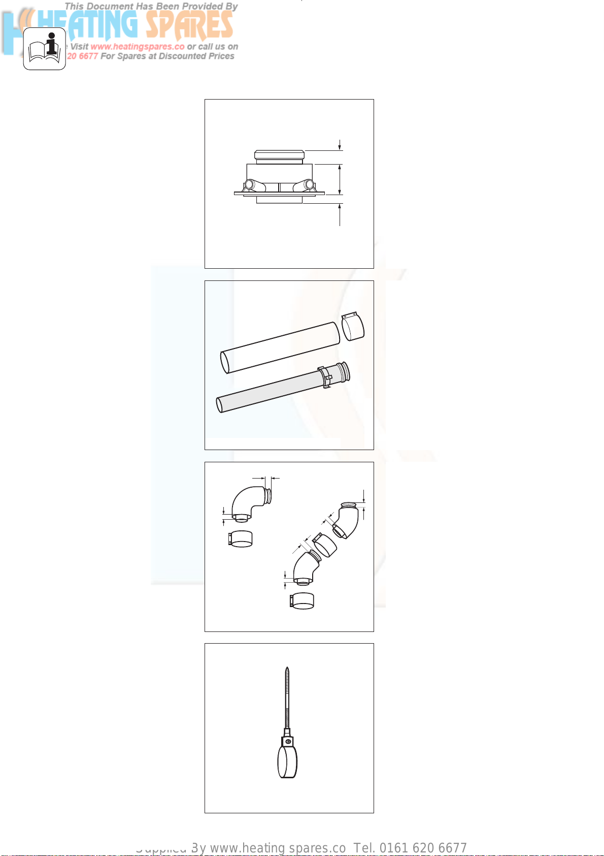
Supplied By www.heating spares.co Tel. 0161 620 6677
PLANNING THE AIR/FLUE DUCT LAYOUT
Fig. 1.1: Appliance connection piece
Appliance connection piece
Ø 80/125
Vaillant Accy. No.: 303 926
(with 2 measuring apertures)
25
58
18
Air/flue duct extension (PPs) 470 mm,
Ø 80/125
Vaillant Accy. No.: 303 202
Air/flue duct extension (PPs) 970 mm,
Ø 80/125
Vaillant Accy. No.: 303 203
☞ Use one clip per extension to
support the air/flue duct.
Fig. 1.2: Extensions, Ø 80/125
25
15
25
15
Fig. 1.3: Elbow joints, Ø 80/125
Air/flue duct extension (PPs)1970 mm,
Ø 80/125
Vaillant Accy. No.: 303 205
GU_LAZ 70/0
Elbow (PPs), 87°, Ø 80/125
Vaillant Accy. No.: 303 210
25
Bends (PPs), 45° (pack of 2),
15
Ø 80/125
Vaillant Accy. No.: 303 211
GU_LAZ 71/0
Flue support clips, Ø 125 (pack of 5)
Vaillant Accy. No.: 303 616
Fig. 1.4: Flue support clips, Ø 125 or Ø 80
40
GU_LAZ 72/0
Page 97
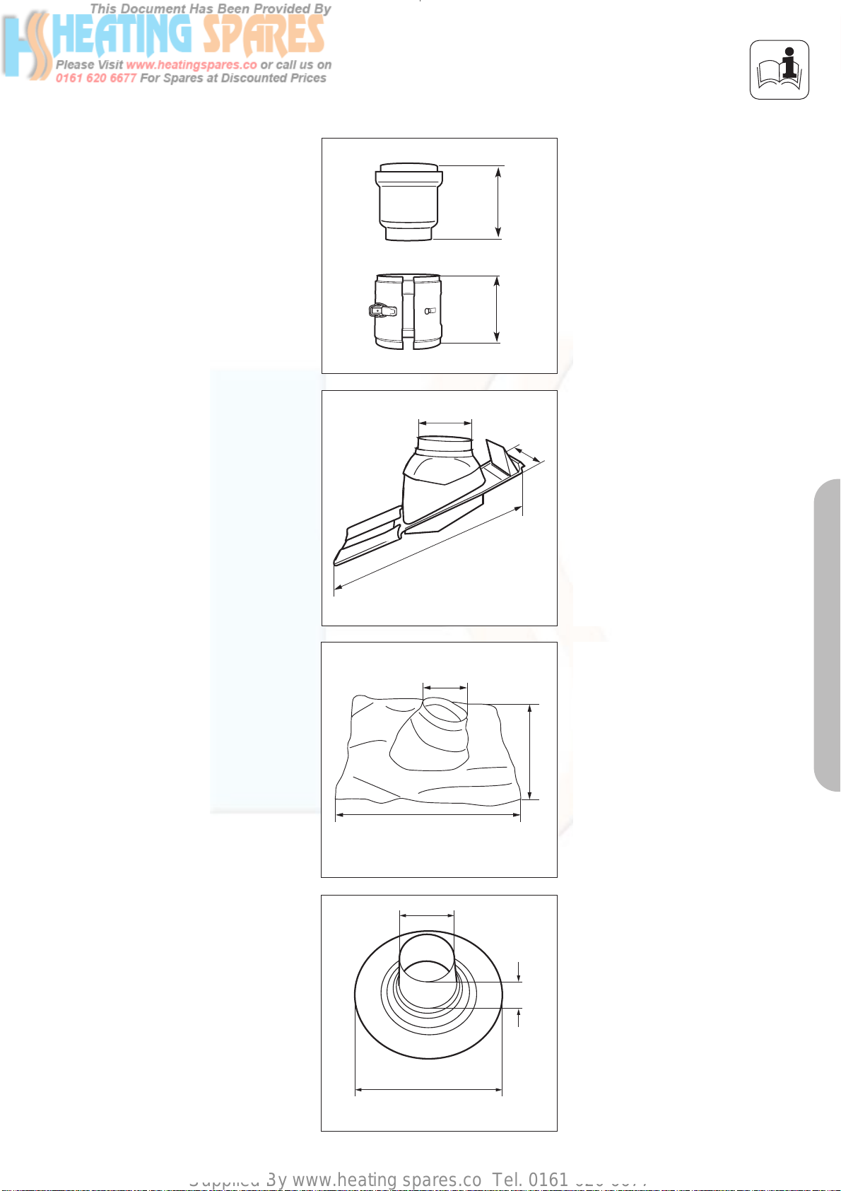
Supplied By www.heating spares.co Tel. 0161 620 6677
PLANNING THE AIR/FLUE DUCT LAYOUT
Sliding sleeve (PPs), Ø 80/125
Vaillant Accy. No.: 303 215
164
120
Fig. 1.5: Sliding sleeve, Ø 80/125
132
498
Fig. 1.6: Adjustable roof tile for pitched roof
132
255
GU_LAZ 76/0
Adjustable roof tiles for pitched roof
Vaillant Accy. No.: 009 076 (black)
GU_LAZ 41/0
Flexible pitched roof seal (black)
Vaillant Accy. No.: 303 980
495
PART 2 CONCENTRIC 80/125
495
Fig. 1.7: Flexible pitched roof seal
130
390
Fig. 1.8: Flat roof penetration collar
Flat roof penetration collar
Vaillant Accy. No.: 009 056
153
GU_LAZ 42/0
41
Page 98

Supplied By www.heating spares.co Tel. 0161 620 6677
PLANNING THE AIR/FLUE DUCT LAYOUT
Maximum flue lengths for use with ecoMAX
ecoMAX
Accessories Accy. No.
Horizontal
flue systems
Vertical
flue systems
303 209 Max. permitted
303 200
concentric
flue length
Max. permitted
concentric
flue length
613/2 E 618/2 E 622/2 E pro 18 E
pro 28 E
13.0 m
incl.
1 elbow 87°
Maximum length of flue is reduced by 2.5 m for each additional 90° elbow.
Maximum length of flue is reduced by 1.0 m for each additional 45° elbow.
14.0 m
Maximum length of flue is reduced by 2.5 m for each additional 90° elbow
Maximum length of flue is reduced by 1.0 m for each additional 45° elbow
25.0 m
incl.
1 elbow 87°
27.0 m
30.0 m
incl.
1 elbow 87°
31.0 m
20.0 m
incl.
1 elbow 87°
20.0 m
Accessories Accy. No.
Horizontal
flue systems
Vertical
flue systems
303 209 Max. permitted
303 200
concentric
flue length
Max. permitted
concentric
flue length
ecoMAX
824/2 E 828/2 E 635/ E
835/ E
25.0 m
incl.
1 elbow 87°
Maximum length of flue is reduced by 2.5 m for each additional 87° elbow.
Maximum length of flue is reduced by 1.0 m for each additional 45° elbow.
26.0 m
Maximum length of flue is reduced by 2.5 m for each additional 90° elbow
Maximum length of flue is reduced by 1.0 m for each additional 45° elbow
30.0 m
incl.
1 elbow 87°
29.0 m
21.0 m
incl.
1 elbow 87°
22.0 m
42
Page 99
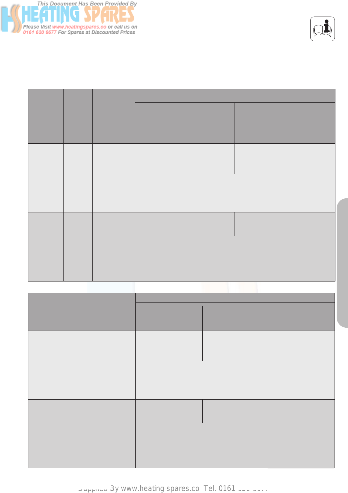
Supplied By www.heating spares.co Tel. 0161 620 6677
PLANNING THE AIR/FLUE DUCT LAYOUT
Maximum flue lengths for use with ecoTEC
Accessories Accy. No.
Horizontal
flue systems
303 209 Max. permitted
concentric
flue length
Maximum length of flue is reduced by 2.5 m for each additional 90° elbow.
Maximum length of flue is reduced by 1.0 m for each additional 45° elbow.
plus 612
plus 615
13.0 m
incl.
1 elbow 87°
ecoTEC
plus 618
plus 624
plus 630
plus 824
plus 831
25.0 m
incl.
1 elbow 87°
Vertical
flue systems
Accessories Accy. No.
Horizontal
flue systems
303 200
303 209 Max. permitted
Max. permitted
concentric
flue length
concentric
flue length
14.0 m
Maximum length of flue is reduced by 2.5 m for each additional 90° elbow
Maximum length of flue is reduced by 1.0 m for each additional 45° elbow
ecoTEC
plus 637
plus 837
21.0 m
incl.
1 elbow 87°
Maximum length of flue is reduced by 2.5 m for each additional 87° elbow.
Maximum length of flue is reduced by 1.0 m for each additional 45° elbow.
pro 24
pro 28
25.0 m
incl.
1 elbow 87°
27.0 m
plus 415
plus 418
plus 428
plus 438
20.0 m
incl.
1 elbow 87°
PART 2 CONCENTRIC 80/125
Vertical
flue systems
303 200
Max. permitted
concentric
flue length
Maximum length of flue is reduced by 2.5 m for each additional 90° elbow
Maximum length of flue is reduced by 1.0 m for each additional 45° elbow
23.0 m
27.0 m
20.0 m
43
Page 100
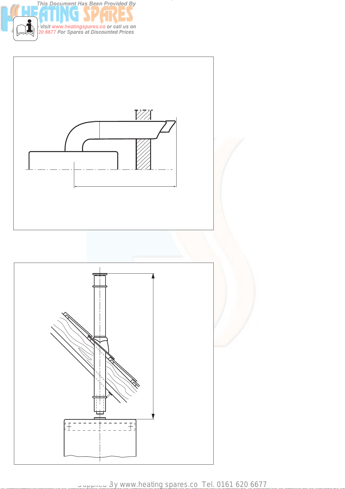
Supplied By www.heating spares.co Tel. 0161 620 6677
PLANNING THE AIR/FLUE DUCT LAYOUT
Maximum flue length
Fig. 1.9
LAS Euro B/S 074/0
Maximum flue length
Fig. 1.10
44
LAS Euro B/S 074/0
 Loading...