


To be left with the user
Instructions for Use, Installation
and Servicing
ecoMAX pro
Wall hung condensing
boilers for traditional open vented
systems
GB
18 E
28 E

Instructions for Use, Installation and Servicing ecoMAX pro2
Table of Contents
Page
1 List of Contents . . . . . . . . . . . . . . . . . . . . . . . . . . . . . . . . . . . . . . . 4
1.1 Contents included with ecoMAX pro boiler
. . . . . . . . . . . . . 4
2 Introduction
. . . . . . . . . . . . . . . . . . . . . . . . . . . . . . . . . . . . . . . . . . 5
2.1 General Information
. . . . . . . . . . . . . . . . . . . . . . . . . . . . . . . 5
2.2 Gas Category
. . . . . . . . . . . . . . . . . . . . . . . . . . . . . . . . . . . . 5
2.3 Gas Safety (Installation and Use) Regulations
. . . . . . . . . . . 5
2.4 Gas Testing and Certification
. . . . . . . . . . . . . . . . . . . . . . . . 5
2.5 CE Mark . . . . . . . . . . . . . . . . . . . . . . . . . . . . . . . . . . . . . . . 5
2.6 Control of Substances Hazardous to Health . . . . . . . . . . . . 5
2.6.1 Insulation Pads . . . . . . . . . . . . . . . . . . . . . . . . . . . . . . . . . . 5
2.7 Spare Parts . . . . . . . . . . . . . . . . . . . . . . . . . . . . . . . . . . . . . 5
2.8 Manual Handling Guidance
. . . . . . . . . . . . . . . . . . . . . . . . . 5
2.9 Warnings
. . . . . . . . . . . . . . . . . . . . . . . . . . . . . . . . . . . . . . . 5
2.10 Protection Against Freezing
. . . . . . . . . . . . . . . . . . . . . . . . . 6
2.11 Boilers Installed in a Compartment or Cupboard . . . . . . . . 6
2.12 Boiler Casing . . . . . . . . . . . . . . . . . . . . . . . . . . . . . . . . . . . 6
2.13 Condensate Drain . . . . . . . . . . . . . . . . . . . . . . . . . . . . . . . . 6
2.14 Pluming from flue terminal . . . . . . . . . . . . . . . . . . . . . . . . . 6
2.15 Cleaning . . . . . . . . . . . . . . . . . . . . . . . . . . . . . . . . . . . . . . . 6
2.16 Maintenance and Servicing
. . . . . . . . . . . . . . . . . . . . . . . . . 6
2.17 Guarantee . . . . . . . . . . . . . . . . . . . . . . . . . . . . . . . . . . . . . . 7
3 Operating the Boiler
. . . . . . . . . . . . . . . . . . . . . . . . . . . . . . . . . . . . 7
3.1 Sealed Central Heating Systems only . . . . . . . . . . . . . . . . . 7
3.2 All Systems
. . . . . . . . . . . . . . . . . . . . . . . . . . . . . . . . . . . . . 7
3.3 User Controls
. . . . . . . . . . . . . . . . . . . . . . . . . . . . . . . . . . . 7
3.4 To Turn the Boiler Off
. . . . . . . . . . . . . . . . . . . . . . . . . . . . . . 7
4 General Information
. . . . . . . . . . . . . . . . . . . . . . . . . . . . . . . . . . . . 8
4.1 Sheet Metal Parts . . . . . . . . . . . . . . . . . . . . . . . . . . . . . . . . 8
4.2 Statutory Requirements . . . . . . . . . . . . . . . . . . . . . . . . . . . . 8
4.3 Gas supply . . . . . . . . . . . . . . . . . . . . . . . . . . . . . . . . . . . . . 8
4.4 Technical Data
. . . . . . . . . . . . . . . . . . . . . . . . . . . . . . . . . . . 8
4.5 Electrical Supply . . . . . . . . . . . . . . . . . . . . . . . . . . . . . . . . . 10
4.6 Condensate Drain . . . . . . . . . . . . . . . . . . . . . . . . . . . . . . . . 10
4.7 Heating System Controls
. . . . . . . . . . . . . . . . . . . . . . . . . . . 10
5 Water system
. . . . . . . . . . . . . . . . . . . . . . . . . . . . . . . . . . . . . . . . . 10
5.1 Draining Tap . . . . . . . . . . . . . . . . . . . . . . . . . . . . . . . . . . . . 10
5.2 Safety Valve. . . . . . . . . . . . . . . . . . . . . . . . . . . . . . . . . . . . . 10
5.3 Pump
. . . . . . . . . . . . . . . . . . . . . . . . . . . . . . . . . . . . . . . . . . 11
5.4 Bypass
. . . . . . . . . . . . . . . . . . . . . . . . . . . . . . . . . . . . . . . . . 11
5.5 Inhibitor
. . . . . . . . . . . . . . . . . . . . . . . . . . . . . . . . . . . . . . . . 11
5.6 Open (Vented) Water System
. . . . . . . . . . . . . . . . . . . . . . . . 11
5.7 Domestic Hot Water Cylinder . . . . . . . . . . . . . . . . . . . . . . . 11
5.8 Domestic Hot Water System - unvented . . . . . . . . . . . . . . . 11
5.9 Sealed water Systems . . . . . . . . . . . . . . . . . . . . . . . . . . . . . 12
5.9.1 Safety Valve
. . . . . . . . . . . . . . . . . . . . . . . . . . . . . . . . . . . . . 12
5.9.2 Expansion Vessel
. . . . . . . . . . . . . . . . . . . . . . . . . . . . . . . . . 12
5.9.3 Pressure Gauge
. . . . . . . . . . . . . . . . . . . . . . . . . . . . . . . . . . 12
5.9.4 Domestic Hot Water Cylinder . . . . . . . . . . . . . . . . . . . . . . . 12
5.9.5 Water Makeup . . . . . . . . . . . . . . . . . . . . . . . . . . . . . . . . . . . 12
5.9.6 Filling a Sealed Water System
. . . . . . . . . . . . . . . . . . . . . . . 12
5.10 Water Treatment
. . . . . . . . . . . . . . . . . . . . . . . . . . . . . . . . . . 12
Page
6 Boiler Location and Ventilation . . . . . . . . . . . . . . . . . . . . . . . . . . . 13
6.1 Boiler Location . . . . . . . . . . . . . . . . . . . . . . . . . . . . . . . . . . 13
6.2 Clearances
. . . . . . . . . . . . . . . . . . . . . . . . . . . . . . . . . . . . . . 13
6.3 Timber Frame Buildings . . . . . . . . . . . . . . . . . . . . . . . . . . . 13
6.4 Room Ventilation
. . . . . . . . . . . . . . . . . . . . . . . . . . . . . . . . . 13
6.5 Compartment Ventilation
. . . . . . . . . . . . . . . . . . . . . . . . . . . 13
7 Flue . . . . . . . . . . . . . . . . . . . . . . . . . . . . . . . . . . . . . . . . . . . . . . 14
7.1 Flue Position and Length . . . . . . . . . . . . . . . . . . . . . . . . . . 14
7.2 Flue termination . . . . . . . . . . . . . . . . . . . . . . . . . . . . . . . . . 14
7.3 Internal Flue Installation . . . . . . . . . . . . . . . . . . . . . . . . . . . 15
7.4 Flue Options . . . . . . . . . . . . . . . . . . . . . . . . . . . . . . . . . . . . 15
8 Installation Preparation
. . . . . . . . . . . . . . . . . . . . . . . . . . . . . . . 15
8.1 Unpacking of Boiler
. . . . . . . . . . . . . . . . . . . . . . . . . . . . . . . 15
8.2 Using boiler template . . . . . . . . . . . . . . . . . . . . . . . . . . . . . 15
8.3 Rear flue exit . . . . . . . . . . . . . . . . . . . . . . . . . . . . . . . . . . . . 16
8.4 Other flue options . . . . . . . . . . . . . . . . . . . . . . . . . . . . . . . . 16
8.5 Flue Hole Cutting . . . . . . . . . . . . . . . . . . . . . . . . . . . . . . . . 16
9 Boiler fixing
. . . . . . . . . . . . . . . . . . . . . . . . . . . . . . . . . . . . . . . . . . 16
9.1 Fitting the boiler hanging bracket . . . . . . . . . . . . . . . . . . . . 16
9.2 Boiler Fixing . . . . . . . . . . . . . . . . . . . . . . . . . . . . . . . . . . . . 16
10 Gas, Water and Condensate Connections . . . . . . . . . . . . . . . . . . 17
10.1 Gas Connection
. . . . . . . . . . . . . . . . . . . . . . . . . . . . . . . . . . 17
10.2 Water Connections . . . . . . . . . . . . . . . . . . . . . . . . . . . . . . . 17
10.3 Condensate Drain Connection
. . . . . . . . . . . . . . . . . . . . . . . 17
11 Flue Preparation and Installation . . . . . . . . . . . . . . . . . . . . . . . . . 18
11.1 Flue Length
. . . . . . . . . . . . . . . . . . . . . . . . . . . . . . . . . . . . . 18
11.2 Extension pipes
. . . . . . . . . . . . . . . . . . . . . . . . . . . . . . . . . . 18
11.3 Flue Assembly
. . . . . . . . . . . . . . . . . . . . . . . . . . . . . . . . . . . 19
11.4 Flue Attachment To Boiler . . . . . . . . . . . . . . . . . . . . . . . . . . 19
12 Electrical Connections . . . . . . . . . . . . . . . . . . . . . . . . . . . . . . . . . 20
12.1 Mains, external controls and pump connections (mains voltage)
20
12.2 Electrical connections – testing
. . . . . . . . . . . . . . . . . . . . . . 20
13 Commissioning . . . . . . . . . . . . . . . . . . . . . . . . . . . . . . . . . . . . . . 21
13.1 Preliminaries - All Systems
. . . . . . . . . . . . . . . . . . . . . . . . . 21
13.2 Sealed Systems
. . . . . . . . . . . . . . . . . . . . . . . . . . . . . . . . . . 21
13.3 Gas supply . . . . . . . . . . . . . . . . . . . . . . . . . . . . . . . . . . . . . 21
13.4 Initial Lighting
. . . . . . . . . . . . . . . . . . . . . . . . . . . . . . . . . . . 21
13.5 Testing - Gas
. . . . . . . . . . . . . . . . . . . . . . . . . . . . . . . . . . . . 22
13.6 Testing - Heating System
. . . . . . . . . . . . . . . . . . . . . . . . . . . 22
13.7 User Controls and Options . . . . . . . . . . . . . . . . . . . . . . . . . 22
13.8 Temperature Display . . . . . . . . . . . . . . . . . . . . . . . . . . . . . . 22
13.9 Pump Exercise Programme
. . . . . . . . . . . . . . . . . . . . . . . . . 22
13.10 Handover to user
. . . . . . . . . . . . . . . . . . . . . . . . . . . . . . . . . 22
14 Natural Gas to LPG conversion
(ecoMAX pro 28E only)
. . . . . . . . . . . . . . . . . . . . . . . . . . . . . . . . 23

Instructions for Use, Installation and Servicing ecoMAX pro 3
Table of Contents
Page
15 Servicing . . . . . . . . . . . . . . . . . . . . . . . . . . . . . . . . . . . . . . . . . . . 25
15.1 General . . . . . . . . . . . . . . . . . . . . . . . . . . . . . . . . . . . . . . . . 25
15.2 Spark Electrode
. . . . . . . . . . . . . . . . . . . . . . . . . . . . . . . . . . 25
15.3 Burner . . . . . . . . . . . . . . . . . . . . . . . . . . . . . . . . . . . . . . . . . 26
15.4 Combustion Chamber and Heat Exchanger. . . . . . . . . . . . . 27
15.5 Condensate Drain . . . . . . . . . . . . . . . . . . . . . . . . . . . . . . . . 27
15.6 Inner Casing Panel Seal Check
. . . . . . . . . . . . . . . . . . . . . . 27
16 Combustion analysis
. . . . . . . . . . . . . . . . . . . . . . . . . . . . . . . . . . 28
17 Fault Finding . . . . . . . . . . . . . . . . . . . . . . . . . . . . . . . . . . . . . . . . 29
17.1 Status Mode . . . . . . . . . . . . . . . . . . . . . . . . . . . . . . . . . . . . 29
17.2 Fault Memory . . . . . . . . . . . . . . . . . . . . . . . . . . . . . . . . . . . 31
17.3 Fault Codes
. . . . . . . . . . . . . . . . . . . . . . . . . . . . . . . . . . . . . 32
17.4 Fault Finding
. . . . . . . . . . . . . . . . . . . . . . . . . . . . . . . . . . . . 33
18 Short Spare Parts
. . . . . . . . . . . . . . . . . . . . . . . . . . . . . . . . . . . . . 34
19 Boiler Specification . . . . . . . . . . . . . . . . . . . . . . . . . . . . . . . . . . . 35
Instructions for Use, Installation and Servicing ecoMAX pro4
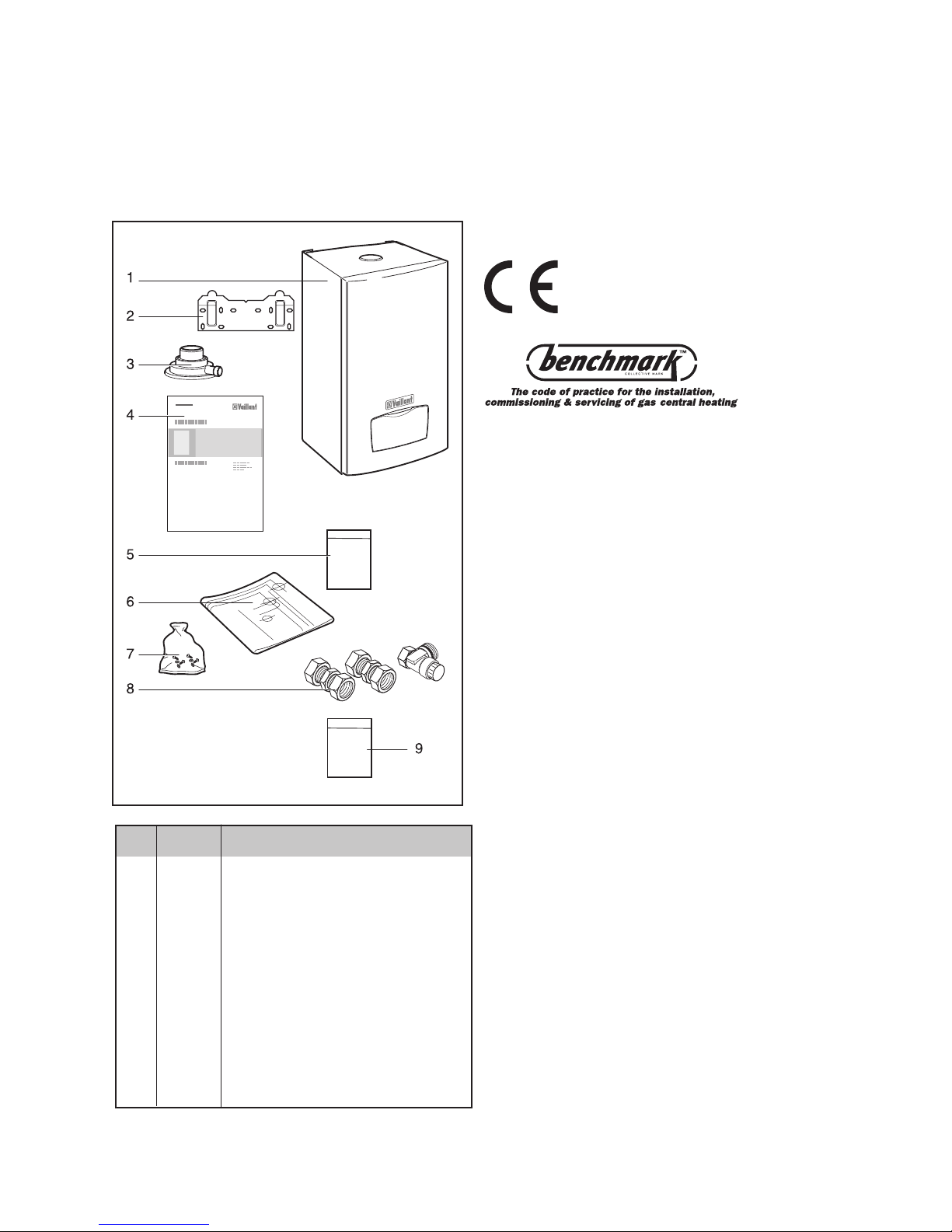
1.1 Contents included with ecoMAX pro boiler
Ensure that all contents are included before commencing
installation.
Item Quantity Description
1 1 Boiler
2 1 Hanging bracket
3 1 Flue connection adaptor
4 1 Instruction booklet
5 2 Guarantee card and envelope and log book
6 1 Template
7 1 Screws/wallplugs
8 1 Gas service valve and compression couplers
9 1 Natural Gas to LPG conversion
databadge oversticker
Vaillant Ltd. support the Benchmark initiative.
Within the information pack you will find a Benchmark
Log Book. It is very important that this is completed
correctly at the time of installation, commissioning and
handover to the user.
List of Contents
Fig 1.1
Items supplied with unit
(ecoMAX pro)
12621

Instructions for Use, Installation and Servicing ecoMAX pro 5
2.1 General Information
Thank you for choosing a Vaillant boiler. The information
given in this booklet will enable you to obtain the best
performance from your boiler.
The Benchmark logbook should be completed by the
installer and/or commissioning engineer and handed to
the user.
NOTE:
This boiler must be installed and serviced by
a competent person in accordance with the
Gas Safety (Installation and Use) Regulations
1998. In the UK 'CORGI' registered installers
undertake the work to a safe and satisfactory
standard.
This boiler is designed to provide central heating from a
fully pumped open-vented or sealed water system with a
fully indirect cylinder.
The central heating water temperature can be adjusted
on the boiler.
Once the controls are set the boiler operates
automatically.
A frost protection programme is also included.
Please read these instructions and follow them carefully
for the correct and economical use of your boiler.
2.2 Gas Category
This boiler is factory set for use on Natural Gas (G20).
ecoMAX pro 28E only can be field adjusted for use on
LPG (propane G31), see page 22-23 for instructions.
2.3 Gas Safety (Installation and Use) Regulations
In your own interests and that of safety, it is the Law
that ALL gas appliances are installed by a competent
person in accordance with the current issue of the above
regulations.
2.4 Gas Testing and Certification
The boiler is tested and certificated for safety and
performance. It is, therefore, important that no alteration
is made to the boiler.
2.5 CE Mark
This boiler meets the requirements of Statutory
Instrument, No. 3083 The Boiler (Efficiency) Regulations,
and therefore is deemed to meet the requirements of
Directive 92/42/EEC on the efficiency requirements for
new hot water boilers fired with liquid or gaseous fuels.
Type test for purposes of Regulation 5 certified by:
Notified body 0086.
Product/production certified by: Notified body 0086.
The CE mark on this appliance shows compliance with:
1. Directive 90/396/EEC on the approximation of the
laws of the Member States relating to appliances burning
gaseous fuels.
2. Directive 73/23/EEC on the harmonisation of the Laws
of the Member States relating to electrical equipment
designed for use within certain voltage limits.
3. Directive 89/336/EEC on the approximation of the
Laws of the Member States relating to electromagnetic
compatibility.
2.6 Control of Substances Hazardous to Health
Under Section 6 of The Health and Safety at Work Act
1974, we are required to provide information on
substances hazardous to health.
The adhesives and sealants used in this appliance are
cured and give no known hazard in this state.
2.6.1 Insulation Pads
These can cause irritation to skin, eyes and the
respiratory tract.
If you have a history of skin complaint you may be
susceptible to irritation. High dust levels are usual only if
the material is broken.
Normal handling should not cause discomfort, but follow
normal good hygiene and wash your hands before
eating, drinking or going to the lavatory.
If you do suffer irritation to the eyes or severe irritation to
the skin seek medical attention.
2.7 Spare Parts
Only original Vaillant spare parts may be used.
2.8 Manual Handling Guidance
During the appliance installation and the replacement of
the heat exchanger it will be necessary to employ
caution and assistance whilst lifting as the appliance or
component exceeds the recommended weight for a one
man lift.
In certain situations it may be required to use a
mechanical handling aid.
Take care to avoid trip hazards, slippery or wet surfaces.
2.9 Warnings
Gas Leak or Fault
If a gas leak or fault exists or is suspected, turn off the
gas emergency control valve immediately. Eliminate all
sources of ignition, i.e. smoking, blowlamps, hot air guns
etc. Do not operate electrical lights or switches either on
or off. Open all doors and windows, ventilate the area.
Clearances
If fixtures are positioned close to the boiler, space must
be left as shown in Fig. 6.1. Enough space must also be
left in front of the boiler to allow for servicing.
2 Introduction

Instructions for Use, Installation and Servicing ecoMAX pro6
Sheet Metal Parts
This boiler contains metal parts (components) and care
should be taken when handling and cleaning, with
particular regard to edges.
Sealed Components
Under no circumstances must the User interfere with any
sealed component as this could result in a
potentially dangerous situation arising.
Electrical Supply Failure
This boiler must be earthed.
The boiler will not work without an electrical supply.
Normal operation of the boiler should resume when the
electrical supply is restored.
Reset any external controls to resume normal operation
of the central heating.
If the boiler does not resume normal operation turn the
mains reset switch off and on. If the boiler does not
resume normal operation after this the overheat
thermostat may have operated. The overheat
thermostat would only operate under abnormal
conditions and, under these circumstances; it would be
advisable to consult your installation / servicing
company.
2.10 Protection Against Freezing
The boiler has a built in frost protection programme as
long as the electricity and gas are left switched on.
This device operates the burner and system pump when
the temperature inside the boiler falls to 3 °C.
Any other exposed areas of the system should be
protected by a separate frost thermostat.
If the mains electricity and gas are to be turned off for
any long periods during severe weather, it is
recommended that the whole system, including the
boiler, should be drained to avoid the risk of freezing.
Make sure that, if fitted, the immersion heater in the
cylinder is switched off.
If you have a sealed water system contact your
installation/ servicing company as draining, refilling and
pressurising MUST be carried out by a competent
person.
As a safety feature the boiler will stop working if the
condensate drain becomes blocked. During freezing
conditions this may be due to the forming of ice in the
condense drain external to the house. Release an ice
blockage by the use of warm cloths on the pipe. The
boiler should then restart. Contact your installation/
servicing company if the fault persists.
2.11 Boilers Installed in a Compartment or Cupboard
If the boiler is fitted into a compartment or cupboard it
does not require ventilation openings.
Do not use the compartment or cupboard for storage.
Important information 2

Instructions for Use, Installation and Servicing ecoMAX pro 7
2 Introduction 3 Operating the boiler
3.3 User Controls
Slide the On / Off control down to the I position to turn on
the boiler. The operating indicator will illuminate (green)
to show that the boiler is on.
The temperature of the central heating water can be
adjusted by pushing the mode button (
) until the
radiator symbol is displayed. Pushing the + or - buttons
will then set the water temperature as desired. (Typical
setting temperatures for a normal radiator heating sytem
will be in the range of 60 °C to 80 °C. Note that set
temperatures below 60 °C will not sufficiently heat any
hot water cylinder). To return to the normal mode push
the mode button (
) until the display shows the current
temperature of water in the boiler.
When the boiler is operating the flame symbol will be
shown in the display. The bar symbol is also shown and
this indicates the modulating output of the boiler. The
boiler will automatically modulate to the output needed
by the heating system - the more bars that are displayed,
the higher the output.
The ecoMAX pro is a fan flue appliance and the
operation of the fan may be heard when the boiler
is running and for a short period after the boiler has
stopped. Should a fault condition occur the operating
indicator will flash red and will be accompanied by
an "F" symbol in the display. To reset the boiler slide
the On / Off control to the Off (O) position and after 5
seconds back to the On (I) position. The boiler should
now operate. If the fault persists contact your installer /
service provider. The ecoMAX pro has a Holiday / frost
mode. If you are going on holiday and do not want the
boiler to be operated by the external heating controls
press the mode button (
) until the MODE indicator
flashes in the left hand edge of the display. Then press
the + or - button until the arrow indicator points to the
holiday symbol (
). The boiler will now only operate if
necessary for frost protection of the boiler itself as well
as running a daily pump exercise programme to prevent
sticking. It will not be turned on and off by the external
heating controls. If a system frost protection thermostat
has been fitted this will remain active.
3.4 To Turn the Boiler Off
Normally the boiler will be turned off by the heating
system controls. The mains On / Off control may be used
to switch off the boiler, however it is preferable to leave
the electrical supply on whenever possible to permit
operation of the built-in frost protection and daily pump
exercise programme.
2.17 Guarantee
Our confidence in the quality of craftmanship and
performance of our products is demonstrated by the
Vaillant two year guarantee.
During the first year from installation the guarantee
covers your boiler against manufacturing defects for both
parts and labour. In order to extend this guarantee to the
second year from installation all you have to do is ensure
that your boiler receives a service when it is a year old.
(Please note that the cost of the service is not included in
the guarantee).
Should your boiler develop a fault please contact your
original installer or alternatively contact Vaillant Service
Solutions on 0870 6060 777.
IMPORTANT:
to qualify for your two year guarantee:
Please complete the registration details on the
guarantee card and return in the pre-paid envelope to:
Vaillant Registration Department
Freepost MID 22456
Walsall
WS2 7WD
The registration card must be returned within 30 days of
the boiler being installed.
The boiler must be serviced either by Vaillant or another
competent servicing company (CORGI
registered) within one year of the installation date and
the details recorded in the "Installation, Commissioning
and Service Record Log Book" (this log book should
have been completed and left with you by your installer).
Please note that the cost of the service is not included in
the guarantee.
Vaillant is a member of the Benchmark initiative and fully
supports the aims of the programme. Benchmark has
been introduced to improve the standards of installation
and commissioning of central heating systems in the
UK and to encourage the regular servicing of all central
heating systems to ensure safety and efficiency.
3 Operating the Boiler
3.1 Sealed Central Heating Systems only
CAUTION: A sealed water system must be filled and
pressurised by a competent person.
Only light the boiler when you are sure that the system
and boiler have been filled and pressurised.
The pressure should read at least 0.7 bar, when the
system is cold. If the needle displays a value below this,
follow the instructions left by your installer to refill the
system. Alternatively your installer should be called to
refill the system.
3.2 All Systems
Check that the electrical supply to the boiler is ON at the
external isolator.
Set any remote heating system controls as required.
Fig 3.1
12622

Instructions for Use, Installation and Servicing ecoMAX pro8
IMPORTANT NOTICE:
The boiler is supplied in one pack and the flue is
supplied separately.
This boiler is factory set for use on Natural Gas (G20),
ecoMAX pro 28E only can be field adjusted for use on
LPG (propane G31).
Where no British Standards exists, materials and
equipment should be fit for their purpose and of suitable
quality and workmanship.
Refer to Manual Handling Operations, 1992 regulations.
The installation of this boiler must be carried out by a
competent person in accordance the rules in force in the
countries of destination.
Manufacturer’s instructions must not be taken as
overriding statutory requirements.
4.1 Sheet Metal Parts
WARNING:
When installing the appliance, care should be
taken to avoid any possibility of personal injury
when handling sheet metal parts.
4.2 Statutory Requirements
The installation of the boiler MUST be carried out by a
competent person in accordance with the relevant
requirements of the current issue of:
Manufacturer's instructions supplied.
The Gas Safety (Installation and Use) Regulations,
The Building Regulations, The Building Regulations
(Scotland), The Building Regulations (Northern Ireland),
Water Supply (Water Fittings) Regulations, Water
Bylaws, The Health and Safety at Work Act, Control of
Substances Hazardous to Health, The Electricity at Work
Regulations, the current IEE wiring regulations and any
applicable local regulations.
Detailed recommendations are contained in the current
issue of the following British Standards and Codes
of Practice, BS4814, BS5440 Part 1 and 2, BS5449,
BS5546, BS6700, BS6798, BS6891 and BS7074 Part 1
and 2, BS7478, BS7593, BS7671.
In IE the installation must be carried out in accordance
with the current edition of IS 813 'Domestic Gas
Installations', the current Building Regulations and
reference should be made to the current ETCI rules for
electrical installation.
4.3 Gas Supply
The gas installation must be in accordance with the
current issue of BS6891. In IE this is the current edition
of IS813.
The supply from the governed meter must be of
adequate size to provide a steady inlet working pressure
of 20mbar (8in wg) at the boiler.
On completion, test the gas installation for soundness
using the pressure drop method and suitable leak
detection fluid, purge in accordance with the above
standard.
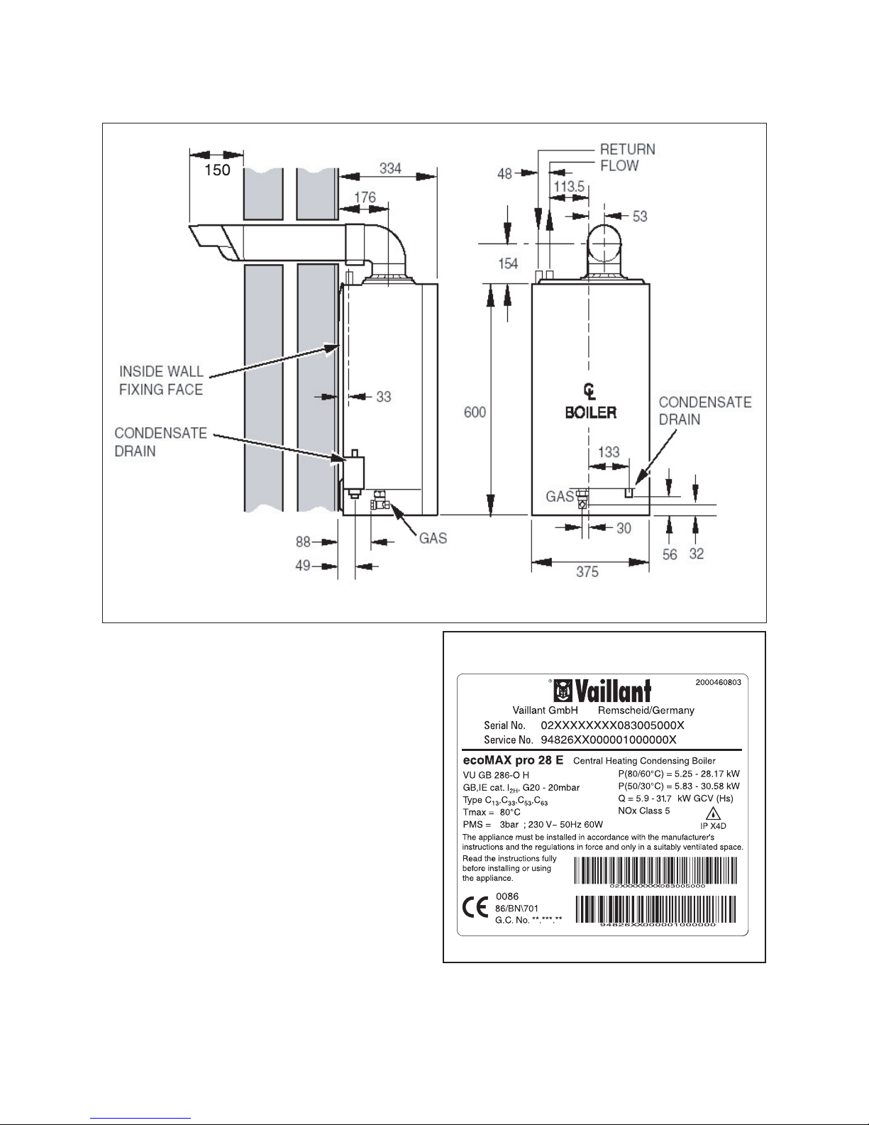
4.4 Technical Data
All dimensions are given in millimetres (except as noted).
See Fig. 4.1.
The data label is positioned on the combustion chamber
cover see fig. 4.2.
The data label includes the product Gas Council number;
18E - 41 044 30
28E - 41 044 31
4 General information
Instructions for Use, Installation and Servicing ecoMAX pro 9
Fig 4.1
12623
12624
Fig 4.2
4 General information
Instructions for Use, Installation and Servicing ecoMAX pro10
4.5 Electrical Supply
The boiler must be earthed.
All system components shall be of an approved type
and all wiring to current I.E.E. wiring regulations. In IE
reference should be made to the current edition of the
ETCI rules.
The boiler must be connected to a permanent 230 V ac,
50 Hz supply.
Connection of the whole electrical system of the boiler,
including any heating controls, to the electrical supply
must be through one common isolator and must be fused
3 Amp maximum. Isolation should be by a double pole
switched fused spur box, with a minimum gap of 3mm for
both poles. The fused spur box
should be readily accessible and preferably adjacent to
the appliance. It should be identified as to its use.
Alternatively connection can be made through an
unswitched shuttered socket and 3A fused 3-pin plug
both to the current issue of BS 1363 may be used,
provided they are not used in a room containing a bath
or shower. The colours of three core flexible cable are,
blue - neutral, brown - live, green and yellow - earth.
4.6 Condensate Drain
A plastic drain pipe must be fitted to allow discharge of
condensate to a drain.
Condensate should, if possible, be discharged into the
internal household draining system. If this is not
practical, discharge can be made externally into the
household drainage system or a purpose designed soak
away, see Section 10.3 for more details.
4.7 Heating System Controls
It is recommended that a programmer and room
thermostat control the boiler.
Thermostatic radiator valves may be installed, however
they must not be fitted in a room where the room
thermostat is located.
NOTE:
All systems must have at least one radiator not
fitted with a thermostatic valve.
NOTE:
For further information, see the current issue of
the Building Regulations, approved document
L1, and the references:
1) GIL 59, 2002: Central heating system specification
(CheSS)
and
2) GPG 302, 2001: Controls for domestic central heating
system and hot water. BRECSU.
5 Water system
5.1 Draining Tap
A draining tap must be provided at the lowest point of the
system, which will allow the entire system and hot water
system to be drained.
Draining taps shall be to the current issue of BS 2879.
5.2 Safety Valve
A safety valve need not be fitted to an open-vented
system. See also section 5.9.1.
Fig 5.1
12625
Fig 5.2
12626
4 General information 5 Water system
Instructions for Use, Installation and Servicing ecoMAX pro 11
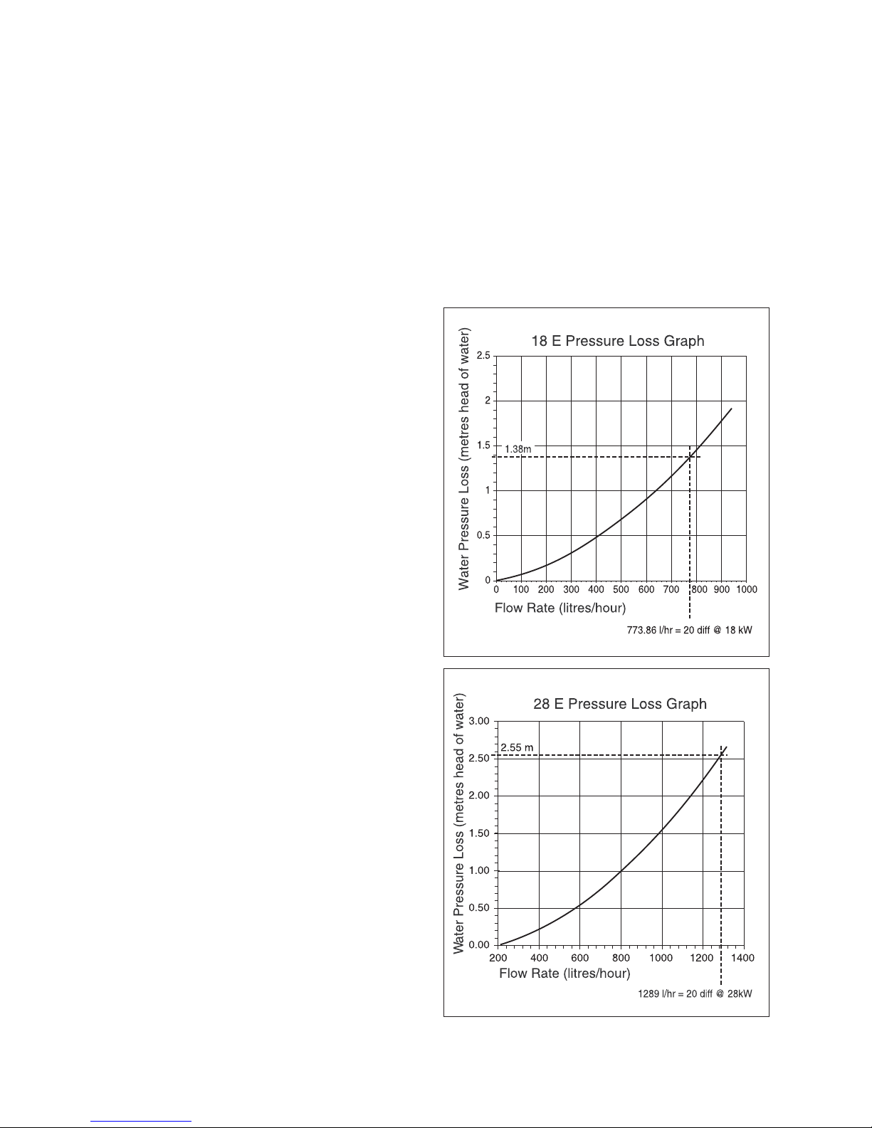
5.3 Pump
The pump should be fitted on the flow pipe from the
boiler and have isolating valves each side.
A variable duty pump should be set to give a
temperature difference of no greater than 20 °C
between the flow and return, with the thermostat set
at “MAX”, which is about 80 °C, to give a flow rate as
shown in table 5.1.
See chart for pressure loss of the boiler, Fig. 5.1 or 5.2.
High resistance microbore systems may require a higher
duty pump.
5.4 Bypass
A bypass is not required on the central heating system
unless all radiators are fitted with thermostatic radiator
valves or the system controls could allow the boiler and
pump to operate when there is no flow.
Where a bypass has to be fitted, the bypass must be
placed at least 1.5 metres away from the boiler.
5.5 Inhibitor
Attention is drawn to the current issue of BS 5449 and
BS 7593 on the use of inhibitors in central heating
systems.
If an existing system is to be reused take special care
to drain the entire system, including the radiators, then
thoroughly cleaning out before fitting the boiler whether
or not adding an inhibitor.
For advice please refer to 5.10, Water Treatment.
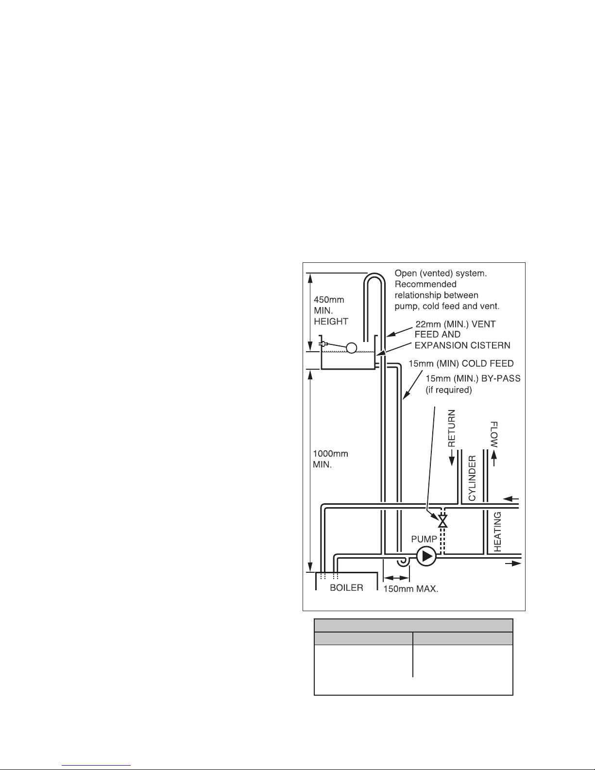
5.6 Open (Vented) Water System
The boiler must be supplied from an unrestricted water
supply taken from a feed and expansion cistern situated
at a maximum height of 27 metres (90ft) above the
boiler.
The cold feed must be 15mm minimum size.
The vent must rise continuously and be unrestricted.
It is important that the relative positions of the pump, cold
feed and open vent are as shown in Fig. 5.3.
5.7 Domestic Hot Water Cylinder
WARNING:
Single feed indirect cylinders are not suitable.
The domestic hot water cylinder must be of the double
feed fully indirect coil type.
5.8 Domestic Hot Water System - unvented
Where a storage system will not have a vent to
atmosphere the installation must comply with the
Building Regulations and local Water Company bylaws,
see also the current issue of BS5546 and BS6700. In IE
the requirements given in the current edition of IS 813
and the current Building Regulations must be followed. If
fitting to an existing system the local authority should be
informed.
NOTE:
ecoMAX pro boilers are not suitable for use
with Vaillant VANTAGE unvented cylinders and
MUST not be used in connection with these cyl
-
inders.
Model Minimum flow rate
ecoMAX pro 18 E 773.8 litres/hr
ecoMAX pro 28 E 1289 litres/hr
This is equal to 20 °C differential at maximum heat input.
TABLE 5.1
Fig 5.3
12627
5 Water system
 Loading...