

Vaillant TURBOmax VUW 242/1 E, TURBOmax VUW 282/1 E, ECOmax VUW 236 E, ECOmax VUW 286 E, ECOmax 824 E Installation Instructions Manual
...Page 1

INSTALLATION INSTRUCTIONS
Optional central heating time clocks for Vaillant Combination boilers:
TURBOmax VUW 242/1 E, VUW 282/1 E
ECOmax VUW 236 E, VUW 286 E
ECOmax 824 E, 828 E
24 hour time clock Art. No. 300 880
7 day time clock Art. No. 300 881
NOTE:
This time clock must only be installed by a competent person.
All above listed boilers have a built in frost thermostat. This time clock is not suitable for use with an external frost thermostat.
Page 2
2
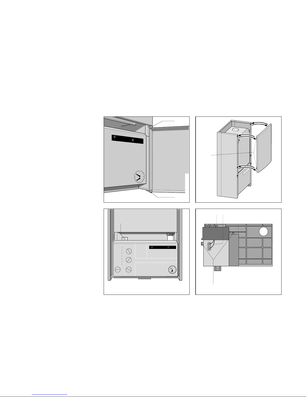
1. Plug in time clock
installation with a
TURBOmax
VUW 242/1 E
VUW 282/1 E
•
Isolate the boiler from the mains
electricity supply by disconnecting the
plug at the socket outlet (if there is an
isolating switch only, remove the fuse
from the switch).
•
Remove bottom hinge screw (1, fig.
1a) and pull lower door panel forward
and down to release it from the top
hinge pin (2, fig. 1a).
•
Slide the top panel up to release the
retaining clips (1, fig. 1b).
•
Undo screw (1, fig. 1c) and lower front
control panel.
•
Disconnect ignition leads (2, fig. 2)
from rear of control box, and remove
terminal strip cover and back of control
box by undoing three screws (1, fig. 2).
1
Fig. 1b
12
1
Fig. 2
EC_Regler_(24h_7d)_007/0
EC_Regler_(24h_7d)_003/0
2
1
Fig. 1a
GW 606/1
1
Fig. 1c
EC_Regler_(24h_7d)_008/0
Page 3
3
1
2
O
O
3
4
7
8
9
1
2
3
4
7
8
9
2
1
3
Fig. 3
EC_Regler_(24h_7d)_001/0
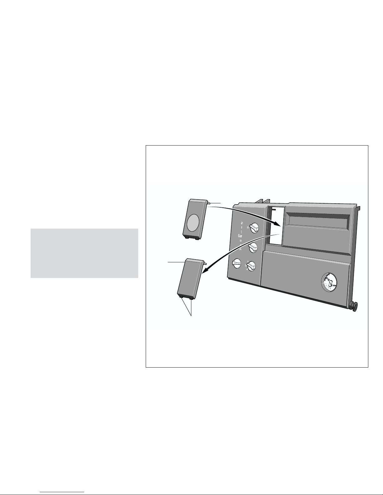
•
Release the time clock blanking plate
(1, fig. 3) from the control box by
pushing the retaining clips (2, fig. 3)
down. The time clock blanking plate
can now be pivoted forwards on
locating lugs (3, fig. 3) and removed.
•
Fit the time clock by first passing the
connecting lead through the hole left
by the time clock blanking plate. Insert
locating lugs (3, fig. 3) into control box
and pivot upwards to locate onto
retaining clips.
(Note: The ribbon cable is supplied with
two plug in connectors. Always utilise
the connector nearest to the timer.
The plug at the end of the cable is
required when the timer is used as a
spare part replacement for earlier
TURBOmax/ECOmax boilers).
Page 4
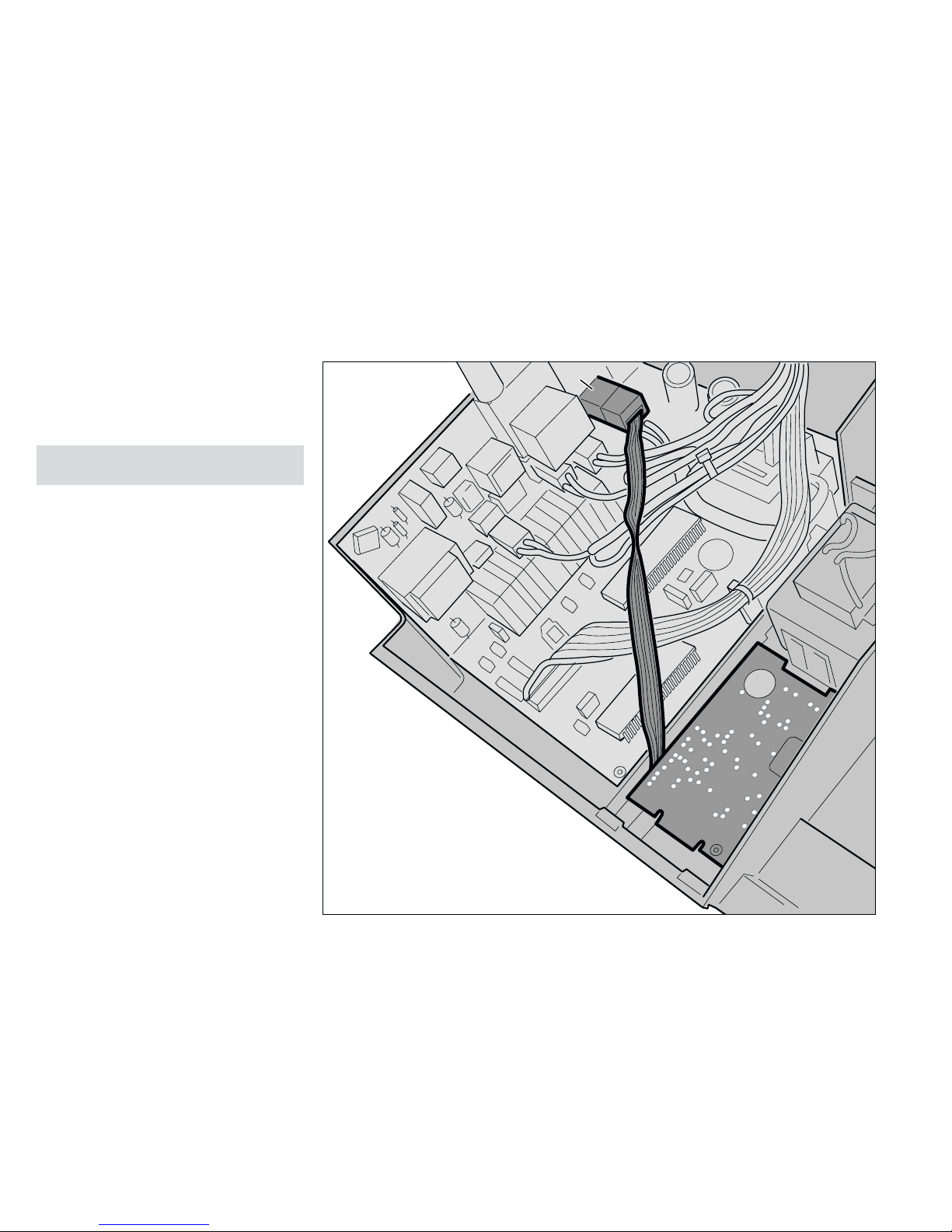
•
Connect the time clock lead to the
control board at the purpose provided
connection point (1, fig. 4).
The clock lead should be connected
to the pins marked X14.
(Note: The time clock operates on low
voltage DC).
•
Connect the room thermostat (if
required).
The boiler is supplied with a link wire
fitted between terminals 3 and 4 of the
boiler terminal strip. If a room thermostat
is used, this link wire should be
removed and the room thermostat
connected as shown in fig. 13.
•
Unless already carried out, complete
the electrical installation by connecting
a 230 V~ 50 Hz electrical supply,
fused at 3A, to the boiler as detailed in
the boiler installation instructions.
•
Refit the back of the control box and
terminal strip cover and secure with
screws (1, fig. 2).
•
Reconnect ignition leads (2, fig. 2).
•
Raise the control box and secure in
position with screw (1, fig. 1c).
•
Carry out the commissioning and
testing as detailed in the Instructions for
Installation and Servicing supplied with
the boiler.
•
Refer to users instructions for details on
setting and operating the time clock.
4
1
Fig. 4
EC_Regler_(24h_7d)_002/0
Page 5
5
1
Fig. 5
EC_Regler_(24h_7d)_014/0
1
Fig. 6
EC_Regler_(24h_7d)_014/0
2. Plug in time clock
installation with an
ECOmax
VUW 236 E, VUW 286 E
•
Isolate the boiler from the mains
electricity supply by disconnecting the
plug at the socket outlet (if there is an
isolating switch only, remove the fuse
from the switch).
•
Remove bottom hinge screw (1, fig.
1a) and pull lower door panel forward
and down to release it from the top
hinge pin (2, fig. 1b).
•
Slide the top panel up to release the
retaining clips (1, fig. 1b).
•
Undo screw (1, fig. 5) and lower front
control panel.
•
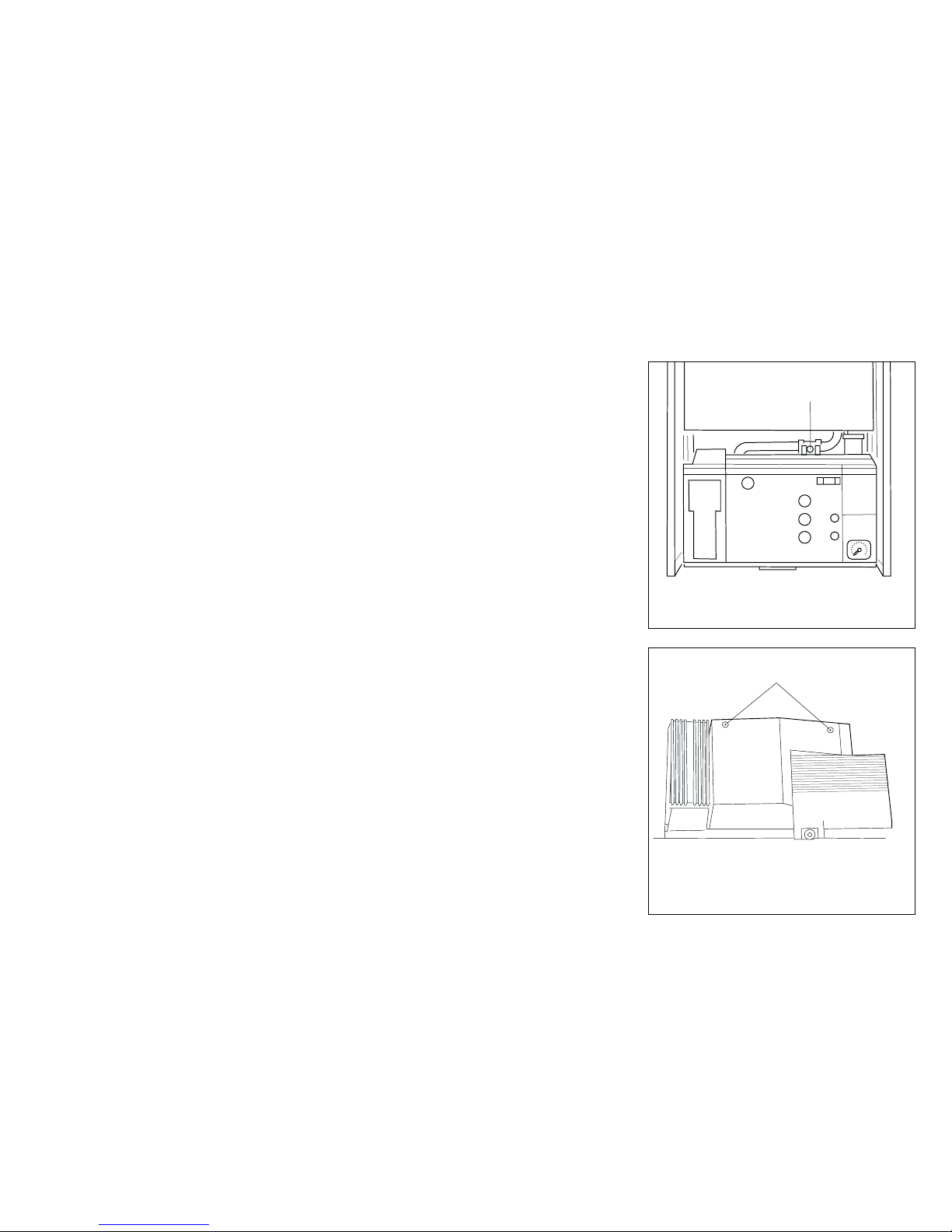
Remove back of control box by
undoing two screws (1, fig. 6).
Page 6

6
3
12
Fig. 7
EC_Regler_(24h_7d)_013/0
•
Release time clock blanking plate (1,
fig. 7) from the control box by pushing
the retaining clips (2, fig. 7) down. The
time clock blanking plate can now be
pivoted forwards on
locating lugs (3, fig. 7) and removed.
•
Fit the time clock by first passing the
connecting lead through the hole left
by the time clock blanking plate. Insert
time clock locating lugs (3, fig. 7) into
control box and pivot upwards to
locate onto retaining clips.
(Note: The ribbon cable is supplied with
two plug in connectors. Always utilise
the connector nearest to the timer.
The plug at the end of the cable is
required when the timer is used as a
spare part replacement for earlier
TURBOmax/ECOmax boilers).
Page 7

•
Connect the time clock lead plug to the
control board at the purpose provided
connection point (1, fig. 8).
The clock lead should be connected
to the pins marked VRC.
(Note: This time clock operates on low
voltage DC).
•
Connect the room thermostat (if
required).
The boiler is supplied with a link wire
fitted between terminals 3 and 4 of the
boiler terminal strip. If a room thermostat
is used, this link wire should be
removed and the room thermostat
connected as shown in fig. 13.
•
Unless already carried out, complete
the electrical installation by connecting
a 230 V~ 50 Hz electrical supply,
fused at 3A, to the boiler as detailed in
the boiler installation instructions.
•
Refit the control box back cover.
•
Raise the control box and secure in
position.
•
Carry out the commissioning and
testing as detailed in the Instructions for
Installation and Servicing supplied with
the boiler.
•
Refer to users instructions for details on
setting and operating the time clock.
7
VRC
1
Fig. 8
EC_Regler_(24h_7d)_009/0
Page 8

8
2
2
Fig. 9b
GU_Ecomax_002/0GB
1
o
n
o
f
f
Fig. 9a
GU_Ecomax_007/0GB
o
n
o
f
f
+
Fig. 9c
GU_Ecomax_003/0GB
3. Plug in time clock
installation with an
ECOmax 824 E, 828 E
•
Isolate the boiler from the mains
electricity supply by disconnecting the
plug at the socket outlet (if there is an
isolating switch only, remove the fuse
from the switch).
•
Lower control panel cover.
•
Remove screw (1, fig. 9a).
•
Release the front case spring retaining
clips located beneath the front edge of
the appliance (2, fig. 9b).
•
Remove the front casing by easing
forward the bottom edge and gently
lifting (fig. 9c).
Page 9

9
on
off
on
+
1
Fig. 10a
GU_Ecomax_008/0GB
3
3
2
1
Fig. 10b
GU_Ecomax_074/0GB
•
Remove control box securing screw (1,
fig. 10a) and lower control box.
•
Disconnect HT lead from rear of control
box (1, fig. 10b).
•
Release mains electrical lead from
securing clip on rear of control box (2,
fig. 10b).
•
Release control box rear cover
retaining clips (3, fig 10b) by gently
easing outwards.
•
Carefully lift control box rear cover and
remove from boiler.
Page 10

10
o
n
o
ff
+
1
3
2
2
Fig. 11
EC_Regler_(24h_7d)_012/0
•
Release time clock blanking plate (1,
fig. 11) from the control box by
pushing the retaining clips (2, fig. 11)
down. The time clock blanking plate
can now be pivoted forwards on
locating lugs (3, fig. 11) and removed.
•
Using a sharp knife, carefully cut a slit
in the sealing grommet at the rear of
the time clock housing. Pass the
connecting lead through the grommet.
•
Insert time clock locating lugs (3, fig.
11) into control box and pivot upwards
to locate onto retaining clips.
(Note: The ribbon cable is supplied with
two plug in connectors. Always utilise
the connector nearest to the timer.
The plug at the end of the cable is
required when the timer is used as a
spare part replacement for earlier
TURBOmax/ECOmax boilers).
Page 11

11
VRC
1
Fig. 12
EC_Regler_(24h_7d)_0011/0
•
Connect the time clock lead plug to the
control board at the purpose provided
connection point (1, fig. 12).
(Note: This time clock operates on low
voltage DC).
•
Connect the room thermostat (if
required).
The boiler is supplied with a link wire
fitted between terminals 3 and 4 of the
boiler terminal strip. If a room thermostat
is used, this link wire should be
removed and the room thermostat
connected as shown in fig. 13.
•
Unless already carried out, complete
the electrical installation by connecting
a 230 V~ 50 Hz electrical supply,
fused at 3A, to the boiler as detailed in
the boiler installation instructions.
•
Refit the control box back cover and
reconnect mains electrical lead and HT
lead (fig. 10b).
•
Raise the control box and secure with
screw (1, fig. 10a).
•
Carry out the commissioning and
testing as detailed in the Instructions for
Installation and Servicing supplied with
the boiler.
•
Refer to users instructions for details on
setting and operating the time clock.
Page 12

12
7543
MAINS
SUPPLY
230 V
50 Hz
LLN
N
N
20 V
DO NOT USE!
3 A FUSE
ROOM
THERMOSTAT
89
Fig. 13
EC_Regler_(24h_7d)_010/0
12 345
M
-+
0
I
Fig. 14
EC_Regler_(24h_7d)_006/0
Boiler Terminal Strip
Refer to boiler installation instructions
for full wiring details
4. Connecting a room
thermostat
5. Timer operation
Note: The timer switch contacts are:–
Closed During off periods
Open During on periods
(see fig. 14)
24 hour/7 day time clock
Remove link wire
between terminals
3 and 4, if room
thermostat is to be
connected
Page 13

13
Page 14

83 20 85 GB
02
0599 V
Printed in Germany - Imprimé en Allemagne
Printed on 100% recycled paper
Head Office Sales 01634 292310
Vaillant Ltd., Vaillant House, Service Solutions 0870 6060777
Medway City Estate, Trident Close, Technical Advice 01634 292392
Rochester, Kent ME 2 4 EZ Training 01634 292370
 Loading...