

Page 1
For the competent person
Installation and maintenance instructions
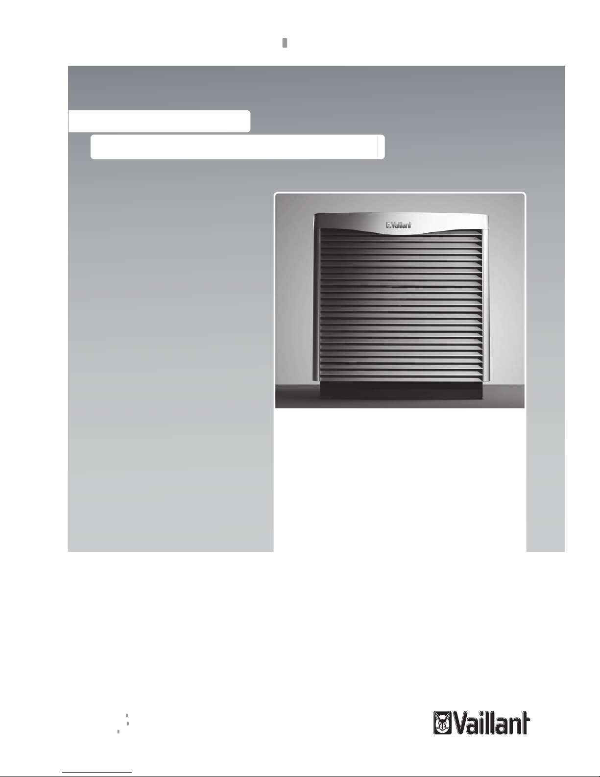
aroCOLLECT
VWL 11/4 SA
GB
Installation and maintenance instructions
Publisher/manufacturer
Vaillant GmbH
Berghauser Str. 40 D-42859 Remscheid
Tel. +49 21 91 18‑0 Fax +49 21 91 18‑2810
info@vaillant.de www.vaillant.de
Page 2

Contents
2 Installation and maintenance instructions aroCOLLECT 0020217119_01
Contents
1 Safety .................................................................... 3
1.1 Action-related warnings ......................................... 3
1.2 Intended use.......................................................... 3
1.3 General safety information .................................... 3
1.4 Regulations (directives, laws, standards) .............. 4
2 Notes on the documentation .............................. 6
2.1 Observing other applicable documents ................. 6
2.2 Storing documents................................................. 6
2.3 Applicability of the instructions .............................. 6
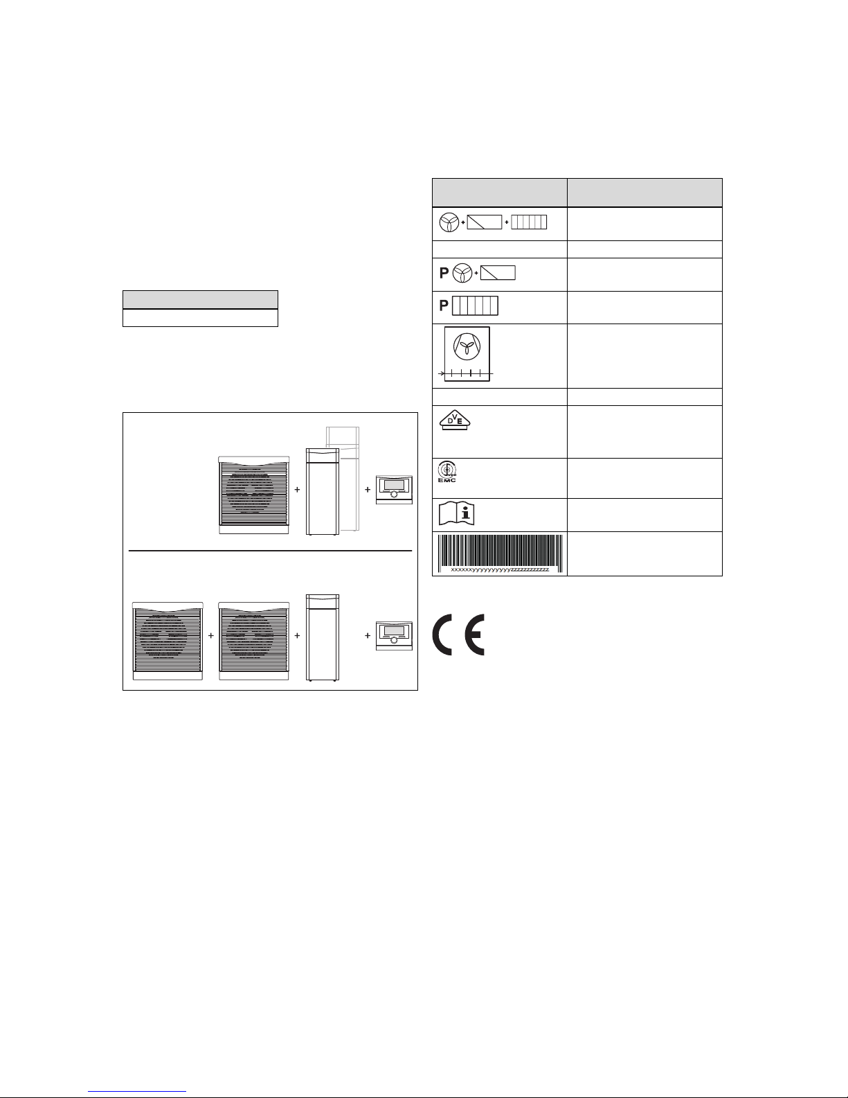
3 System overview.................................................. 6
3.1 Heat pump system design ..................................... 6
4 Product description............................................. 6
4.1 Information on the identification plate.................... 6
4.2 CE label ................................................................. 6
4.3 Product design....................................................... 7
5 Installation............................................................ 7
5.1 Checking the scope of delivery.............................. 7
5.2 Removing the transport locks ................................ 7
5.3 Selecting the installation site ................................. 8
5.4 Dimensions............................................................ 9
5.5 Minimum clearances.............................................. 9
5.6 Creating the foundation ....................................... 11
5.7 Hydraulics installation.......................................... 12
5.8 Filling and purging the brine circuit ...................... 14
5.9 Electrical installation ............................................ 17
6 Start-up ............................................................... 20
6.1 Start-up ................................................................ 20
6.2 Handing the product over to the operator............ 20
7 Inspection and maintenance ............................ 20
7.1 Inspection and maintenance interval ................... 20
7.2 Carrying out inspection and maintenance
work ..................................................................... 21
7.3 Procuring spare parts .......................................... 21
7.4 Cleaning the product............................................ 21
7.5 Cleaning the condensate discharge .................... 21
8 Decommissioning.............................................. 21
8.1 Temporary decommissioning .............................. 21
8.2 Permanently decommissioning............................ 21
9 Customer service............................................... 21
10 Recycling and disposal..................................... 21
Appendix ............................................................................ 22
A Product diagram ................................................ 22
A.1 Product diagram .................................................. 22
B Connection diagram .......................................... 23
C Technical data.................................................... 24
C.1 General................................................................ 24
C.2 Air heat source..................................................... 26
Index ................................................................................... 29
Page 3
Safety 1
0020217119_01 aroCOLLECT Installation and maintenance instructions 3
1 Safety
1.1 Action-related warnings
Classification of action-related warnings
The action-related warnings are classified in
accordance with the severity of the possible
danger using the following warning signs and
signal words:
Warning symbols and signal words
Danger!
Imminent danger to life or risk of
severe personal injury
Danger!
Risk of death from electric shock
Warning.
Risk of minor personal injury
Caution.
Risk of material or environmental
damage
1.2 Intended use
There is a risk of injury or death to the user or
others, or of damage to the product and other
property in the event of improper use or use
for which it is not intended.
The product is intended exclusively for domestic use as an air/brine collector to be
connected to the VWF xx1/4, VWF xx2/4,
VWF xx7/4, VWF xx7/4 S1 or VWF xx8/4
heat pumps. Operating the heat pump in conjunction with the air/brine collector and outside the application limits results in the heat
pump being switched off by the internal control and safety devices.
Intended use includes the following:
– observance of accompanying operating,
installation and servicing instructions for
the product and any other system components
– installing and fitting the product in accord-
ance with the product and system approval
– compliance with all inspection and main-
tenance conditions listed in the instructions.
Intended use also covers installation in accordance with the IP class.
Any other use that is not specified in these
instructions, or use beyond that specified in
this document shall be considered improper
use. Any direct commercial or industrial use
is also deemed to be improper.
Caution.
Improper use of any kind is prohibited.
1.3 General safety information
1.3.1 Risk caused by inadequate
qualifications
The following work must only be carried out
by competent persons who are sufficiently
qualified to do so:
– Installation
– Disassembly
– Installation
– Start-up
– Maintenance
– Repair
– Decommissioning
▶ Observe all instructions that are included
with the product.
▶ Proceed in accordance with the current
state of technology.
▶ Observe all applicable directives, stand-
ards, laws and other regulations.
1.3.2 Danger caused by improper
operation
Improper operation may present a danger to
you and others, and cause material damage.
▶ Carefully read the enclosed instructions
and all other applicable documents, particularly the "Safety" section and the warnings.
▶ Only carry out the activities for which in-
structions are provided in these operating
instructions.
1.3.3 Risk of death due to lack of safety
devices
The schematic drawings included in this document do not show all safety devices required for correct installation.
▶ Install the necessary safety devices in the
system.
▶ Observe the applicable national and inter-
national laws, standards and guidelines.
Page 4

1 Safety
4 Installation and maintenance instructions aroCOLLECT 0020217119_01
1.3.4 Risk of death from electric shock
There is a risk of death from electric shock if
you touch live components.
Before commencing work on the product:
▶ Disconnect the product from the power
supply by switching off all power supplies
(electrical partition with a contact opening
of at least 3 mm, e.g. fuse or line protection switch).
▶ Secure against being switched back on
again.
▶ Wait for at least 3 minutes until the capa-
citors have discharged.
▶ Check that there is no voltage.
1.3.5 Risk of injury due to chemical burns
caused by brine fluid
The brine fluid ethylene glycol is harmful to
health.
▶ Avoid contact with the skin and eyes.
▶ Always wear gloves and protective
goggles.
▶ Do not inhale or swallow.
▶ Observe the safety data sheet that accom-
panies the brine fluid.
1.3.6 Risk of burns due to hot and cold
components
There is a risk of burns and frostbite from any
uninsulated pipelines and from the auxiliary
electric heating.
▶ Only carry out work on the components
once they have reached ambient temperature.
1.3.7 Risk of death due to changes to the
product or the product environment
▶ Never remove, bridge or block the safety
devices.
▶ Do not alter the safety devices in any way.
▶ Do not damage or remove any seals on
components. Only authorised competent
persons or customer services may modify
sealed components.
▶ Do not make any changes to:
– The product itself
– The product environment
– The brine fluid, air and current supply
lines
– The drain line and expansion relief valve
for the heat source circuit
– to constructional conditions that may
affect the operational reliability of the
product
1.3.8 Material damage due to unsuitable
installation surface
The installation surface must be even and
have sufficient load-bearing capacity to support the operating weight of the product. An
uneven installation surface may cause leaks
in the product.
If the installation surface does not have sufficient load-bearing capacity, the product may
topple.
There is a risk of death if the connections are
subject to leaks.
▶ Make sure that the product is positioned
flush against the installation surface.
▶ Ensure that the installation surface has
sufficient load-bearing capacity to bear the
operating weight of the product.
1.3.9 Risk of injury during transport due
to a high product weight
▶ Make sure that the product is transported
by at least two people.
1.3.10 Risk of material damage caused by
using an unsuitable tool
▶ Use the correct tool to tighten or loosen
screw connections.
1.4 Regulations (directives, laws,
standards)
When setting up, installing and operating the
heat pump and the domestic hot water cylinder, you must observe the following points in
particular:
– Local specifications, regulations, rules and
directives regarding electrical connections
– Local specifications, regulations, rules and
directives for the power company
– Local specifications, regulations, rules and
directives for the water supply company
– Local specifications, regulations, rules and
directives regarding the use of geothermal
energy
Page 5

Safety 1
0020217119_01 aroCOLLECT Installation and maintenance instructions 5
– Local specifications, regulations, rules and
directives regarding the integration of heat
source systems and heating installations
– Local specifications, regulations, rules and
directives regarding saving energy
– Local specifications, regulations, rules and
directives regarding hygiene
Page 6
2 Notes on the documentation
6 Installation and maintenance instructions aroCOLLECT 0020217119_01
2 Notes on the documentation
2.1 Observing other applicable documents
▶ You must observe all the operating and installation in-
structions included with the system components.
2.2 Storing documents
▶ Pass these instructions and all other applicable docu-
ments on to the system operator.
2.3 Applicability of the instructions
These instructions apply only to:
Product
VWL 11/4 SA
3 System overview
3.1 Heat pump system design
5 - 11 kW
15 - 19 kW
The heat pump system consists of the following components,
as a minimum:
– Air/brine collector(s)
– Heat pump
– System controller
The heat pump system generates heat in heating installations and in hot water generation by extracting the thermal
energy from a heat source circuit and releasing this into
the heating circuit via the internal refrigeration circuit. At the
same time, there is an opportunity for active cooling to take
place via circulation reversal. For this, the heat pump is connected to the air/brine collector(s). The air/brine collector is
used to exchange heat between the brine circuit and the outside air.
4 Product description
4.1 Information on the identification plate
The identification plate is attached at the factory to the underside of the electronics box.
Information on the identification plate
Meaning
Rated voltage and frequency of
the fan, controller and de-icer
P max Maximum rated power
Rated power of the fan and
controller
De-icer rated power
→ A2/W35
Rated power and pressure of
the air/brine collector at an air
inlet temperature of 2 °C and
a heating flow temperature of
35 °C
IP Level of protection
Verband deutscher Elektrotechniker (German Association for
Electrical, Electronic & Information Technologies)
Electromagnetic Compatibility
in accordance with the Verband
deutscher Elektrotechniker
Read the instructions.
Bar code with serial number,
7th to 16th digit = product article
number
4.2 CE label
The CE label shows that the products comply with the basic
requirements of the applicable directives as stated on the
identification plate.
The declaration of conformity can be viewed at the manufacturer's site.
Page 7
Installation 5
0020217119_01 aroCOLLECT Installation and maintenance instructions 7
4.3 Product design
4.3.1 Front view, closed
1
1 Type designation with
serial number
4.3.2 Front view, open
12
11
3
6
2
1
8
9
4
5
10
7
1 Purging valves
2 Simple identification
plate
3 Electronics box
4 De-icer
5 Connection box
6 Identification plate with
service sticker
7 Warning sticker
8 Connecting the brine
line to the heat pump
(hot brine)
9 Connecting the brine
line from the heat pump
(cold brine)
10 Base (accessory)
11 Condensate tray
12 Ventilator
5 Installation
5.1 Checking the scope of delivery
1. Carefully remove the packaging and padding without
damaging the parts of the product.
2. Check that the scope of delivery is complete.
Quantity Description
1 Box: Cover and side sections of the casing
2 Louvred grill (pre-installed)
1 Air/brine collector
1 Installation material:
– 2 x O-ring seals
– 10 x M8x20 screws (to secure the cover,
the side casing and the air/brine collector
to the base (accessories))
1 Enclosed documentation
5.2 Removing the transport locks
2 x
▶ Remove the transport locks as shown in the illustration.
Page 8
5 Installation
8 Installation and maintenance instructions aroCOLLECT 0020217119_01
5.3 Selecting the installation site
Caution.
Risk of material damage caused by corro-
sion.
Caustic vapours may cause corrosion damage on the product. The extracted air must be
free from ammonia, methane gas and other
corrosive elements.
▶ Do not install the product close to stables
and manure pits.
▶ Set up the product outdoors away from rooms. Depend-
ing on the weather, condensate may form and appear
under the collector.
– Maximum installation height: 2000 m above normal
sea level
▶ Ensure that there is a sufficiently stable, frost-proof, hori-
zontal foundation that meets local requirements and complies with the rules of structural engineering.
▶ For efficiency reasons, the clearance between the heat
pump and the air/brine collector should be kept as small
as possible.
– Total length of the connection line, cold brine and hot
brine: 2 x 30 m
▶ If the clearance between the product and the building
falls below 3 m, position the product in such a way that
the outlet side does not point towards the building.
▶ Assess the installation site to ensure that no persons can
be at risk at the outlet side. No public roads/pathways
should run through the area of the outlet side.
▶ Install the product with the intake side towards the wall
(recommended installation).
▶ Comply with the local and statutory minimum clearances
with regards to:
– Vegetation
– Walls
– Awnings
– Open fire or embers
– Children's toys
▶ When selecting the installation site, take into consider-
ation the fact that, during full load mode in winter, noise
(depending on the current output requirement, up to approx. 66 dB(A) sound power level) is emitted from the
product, and this noise may be amplified by reverberative
surfaces.
▶ Observe the national regulations regarding noise.
Sound propagation form: Hemisphere
Sound propagation with a free-standing air/brine collector.
Sound propagation form: Quarter-sphere
Sound propagation for the adjacent building: On just one
side.
Page 9
Installation 5
0020217119_01 aroCOLLECT Installation and maintenance instructions 9
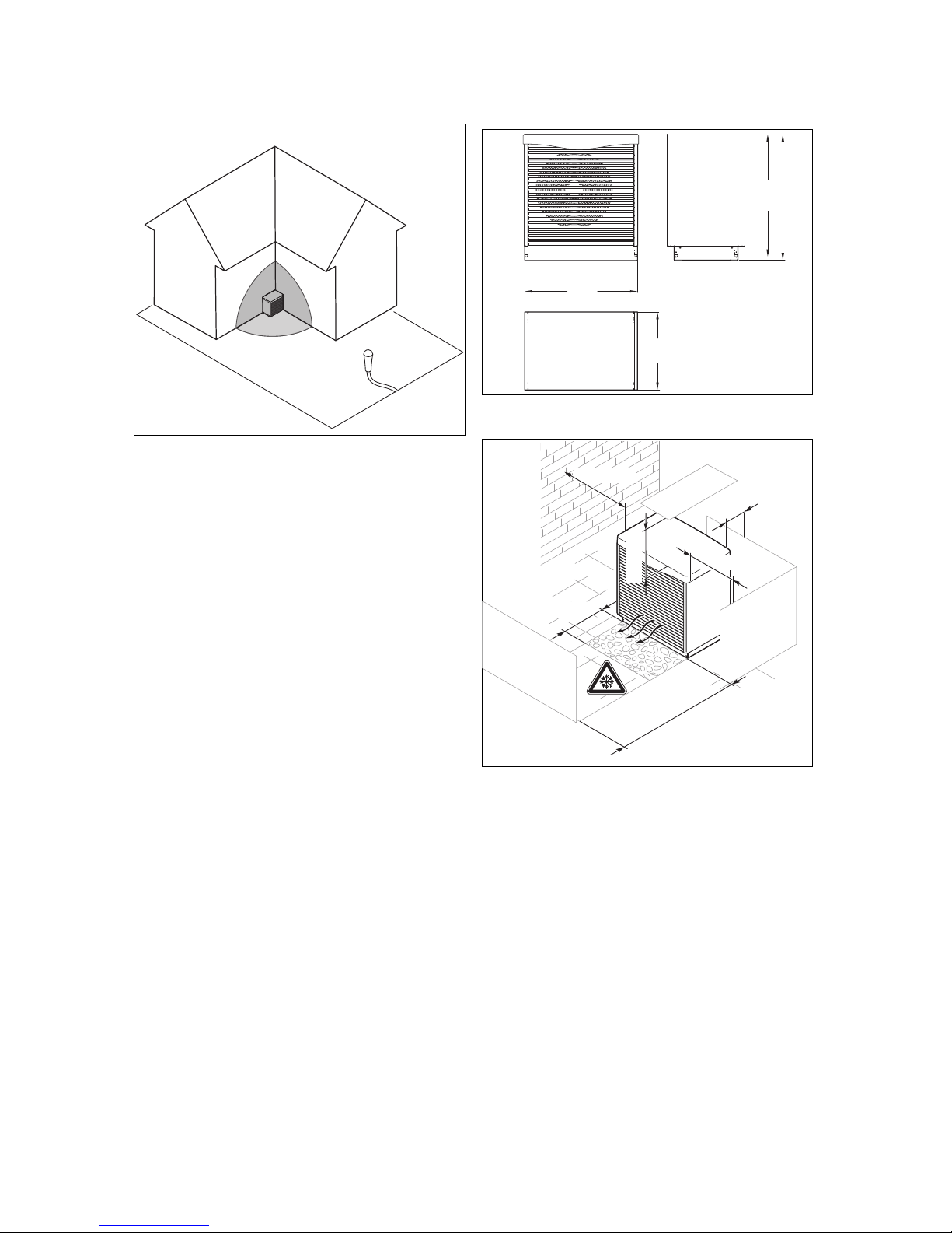
Sound propagation form: An eighth of a sphere
Sound propagation for the adjacent building: On two sides
and at a right-angle.
LWA= L
PFA
– 10 lg S
LWA= Sound pressure level (dB(A))
L
PFA
= Sound power level (dB(A))
S = Sound propagation form* (clearance from the product in
m)²
Sound propagation form: Hemisphere = 6.28
Sound propagation form: Quarter-sphere = 3.14
Sound propagation form: Eighth of a sphere = 1.57
Example
L
PFA
= 54 dB(A), max. sound power level without noise re-
duction
Sound propagation form = Hemisphere = 6.28
Distance to the product = 10 m
LWA= 54 dB(A) – 10 lg (6.28 * 100)
LWA= 54 dB(A) – 10 lg (628)
LWA= 54 dB(A) – 28
LWA= 26 dB(A)
▶ Choose the installation site so that the legally required
emissions values for noise outside of buildings can be
complied with, without having to use the heat pump system's noise reduction function, if possible.
▶ In certain weather conditions, take into consideration
the possibility of black ice forming directly in front of the
product's outlet side; if condensate escapes, the black
ice may form all around the product.
5.4 Dimensions
1192
785
1256
1162
5.5 Minimum clearances
≥ 0,3 m
≥ 0,5 m
≥ 0,5 m
≥ 3 m
ca. 0,5 m
≥ 0,5 m
< +5 °C
Clearances that must be complied with for an air/brine collector
Page 10
5 Installation
10 Installation and maintenance instructions aroCOLLECT 0020217119_01
ca. 0,5 m
≥ 0,3 m
≥ 0,5 m
≥ 0,5 m
≤ 5 m
≥ 3 m
≥ 0,5 m
< +5 °C
< +5 °C
≥ 0,5 m
Clearances that must be complied with for two air/brine collectors
Positioning of the collectors
▶ Use the mounting base, which is available as an access-
ory, for the installation.
▶ To guarantee sufficient air flow and to facilitate mainten-
ance work, observe the minimum clearances that are
specified above.
▶ Ensure that there is sufficient room to install the hydraulic
lines.
▶ If the product is to be installed in areas where heavy
snow falls, ensure that the snow does not accumulate
around the product and that the minimum clearances
specified above are observed. If you cannot ensure this,
install an additional heat generator in the heating circuit.
An elevating base and condensate tray heating are available as accessories.
Page 11

Installation 5
0020217119_01 aroCOLLECT Installation and maintenance instructions 11
▶ If you install two air/brine collectors, you must create a
concrete foundation and use the connection pipe set that
is available as an accessory.
5.6 Creating the foundation
³ 0,8 m
1
3
5
2
4
6
1 Air/brine collector
2 Foundation
3 Compacted gravel
4 Ground
5 Condensate drain pipe
6 Gravel bed in a frost-
free area
1. Prepare the ground for the foundation in accordance
with the illustration.
2. As a condensate drain pipe, route a pipe that drops
vertically and that is ≥ DN 110. Route this pipe as far
as the frost-free ground. To lay the pipe at ground level
and so that it comes out of the mounting base at the
side, use the accessory that is available for this.
A
A
B
B
Ø 12
120 x=cm
34 18
62
52
49
41
Ø 5
14
Ø 7
8
18
110
60
23
15
13
10
26
Ø 7
A Connecting the air/brine
collector to the heat
pump (hot brine)
B Connecting the heat
pump to the air/brine
collector (cold brine)
3. Create a frost-free and stable foundation or set the
product on paving slabs. When doing so, observe the
rules of structural engineering and the instructions that
are enclosed with the recommended VWL S installation
set for PE pipes.
³ 0,8 m
DN 110
4. Establish the connections for a foundation made of paving slabs in accordance with the illustration.
Page 12

5 Installation
12 Installation and maintenance instructions aroCOLLECT 0020217119_01
DN 110
³ 0,8 m
5. Establish the connections for a concrete foundation in
accordance with the illustration.
6. Install the base that is available as an accessory.
5.7 Hydraulics installation
5.7.1 Routing the connection lines
Caution.
Risk of material damage caused by
ground lifting up as a result of frozen
ground.
At operating temperatures close to freezing
level, the ground in the area of the PE pipes
may freeze and therefore damage the structure as a result of the ground lifting up.
▶ Insulate all of the PE lines that are to be
routed under buildings, terraces, pathways, etc. so that they are vapour-diffusion-tight.
▶ If possible, route PE pipes in the ground
with a clearance of 70 cm from each other
and from adjacent supply lines (except for
electrical lines).
The total length (connection lines from the heat pump to the
product and from the product to the heat pump) must be no
greater than 60 m.
▶ Keep the clearance between the product and the heat
pump as short as possible and minimise the use of elbows and angles. This is because each additional pressure loss that is caused by the use of these reduces efficiency.
▶ Route the PE pipes in accordance with the applicable
technical directives.
▶ For a total line length of between ≥ 20 m and 60 m, use
a PE pipe with DN 50 (e.g. PE 80/100, outer diameter
50 mm, wall thickness 4.6 mm). Up to a total line length
of ≤ 20 m, you can also use a PE pipe with DN 40
(e.g. PE 80/100, outer diameter 40 mm, wall thickness
3.7 mm).
▶ When using more than eight PE elbows, use an extra
2 m of pipeline for each elbow.
▶ When using copper pipes, use only copper pipes that
have a cross-section of ≥ 35 mm. If you use a smaller
cross-section (e.g. copper 28 mm), this will result in pressure losses (2 m copper 28 = 8 m copper 35).
Note
If the prescribed line cross-sections are not
complied with, this results in efficiency losses
and reduced annual operating figures.
▶ If required, when routing the PE pipes above-ground,
ensure that they are protected against UV radiation.
Conditions: Installing two air/brine collectors
Page 13

Installation 5
0020217119_01 aroCOLLECT Installation and maintenance instructions 13
≤ 10m DN 40*
> 10m ≤ 30m DN 50*
A
B
A
B
* = one way
▶ Connect the air/brine collector in accordance with the
Tichelmann principle. This means that the air/brine collector with the shorter flow has the longest return.
Caution.
Risk of material damage caused by a leak.
When tightening screwed connections,
ensure that O-rings are inserted correctly
as, otherwise, they may pop out or become
jammed, become damaged, or cause leaks.
▶ Insert the O-rings properly and untwisted
into the cap nuts for the air/brine collector's brine connections.
▶ Screw the cap nuts to the connection adaptors on the
"hot brine" and "cold brine" brine lines in the brine circuit
(cross-reference) on the mounting base.
▶ To purge each individual air/brine collector, install
two shut-off units.
5.7.2 Transporting the product
Caution.
Risk of material damage caused by incor-
rect transport.
▶ Do not transport the product using a hand
truck.
▶ If required, remove the louvred grill to prevent damage.
5.7.3 Installing the product
1. Place the product on the base that is available as an
accessory.
2. Connect the brine lines to the product as shown.
3. Screw the product to the base.
5.7.4 Installing brine lines in the building
71
42a
65
48
64
56
62
61
63
70
72
A
B
A
B
≤ 10m DN 40*
> 10m ≤ 30m DN 50*
42a Expansion relief valve
48 Pressure gauge
56 Heat pumps for brine
filling unit (accessory)
61 Stop valve
62 Stop valve
63 Stop valve
64 Stop valve
65 Brine collecting con-
tainer
70 Stop valve
71 Brine diaphragm expan-
sion tank
72 Stop valve
Page 14

5 Installation
14 Installation and maintenance instructions aroCOLLECT 0020217119_01
A From the heat source
to the heat pump (hot
brine)
B From the heat pump to
the heat source (cold
brine)
* One way
1. Install the brine lines between the product and the heat
pump within the building and using all of the associated
components in accordance with the applicable technical
directives.
Note
Do not install dirt filters in the brine circuit for
a prolonged period of time. The brine fluid is
cleaned during the filling process.
2. Reduce the pre-charge pressure of the brine diaphragm
expansion tank (which is available as an accessory)
from 0.25 MPa (2.5 bar) to 0.10 MPa (1.0 bar).
3. Insulate all of the brine lines and the connections for
the heat pump and product so that they are vapourdiffusion-tight.
Note
Vaillant recommends that you install the
Vaillant heat pump brine filling unit. By doing this, it is then possible to carry out a preparatory partial bleed of the brine circuit, e. g.
the flow and return of the brine circuit to the
product.
5.8 Filling and purging the brine circuit
5.8.1 Calculating the required volume of brine
fluid
▶ Use the information in the following table to calculate the
required volume of brine fluid.
▶ Plan an allowance of 10 l for the calculated volume in
order to facilitate the rinsing process.
▶ Label the vessel for the remaining volume with informa-
tion about the type and concentration of brine fluid and,
after start-up, pass the vessel on to the operator so that
they have brine fluid available for when the tank needs to
be topped up.
Brine fluid volume in the product in litres (± 1
litre)
Total
VWF 5x/4 + VWL 11/4 SA 2.5 + 19 21.5
VWF 57/4 S1 + VWL 11/4 SA 2.5 + 19 21.5
VWF 8x/4 + VWL 11/4 SA 3.1 + 19 22.1
VWF 87/4 S1 + VWL 11/4 SA 3.1 + 19 22.1
VWF 11x/4 + VWL 11/4 SA 3.6 + 19 22.6
VWF 117/4 S1 + VWL 11/4 SA 3.6 + 19 22.6
VWF 157/4 + 2x VWL 11/4 SA 4.5 + 38 42.5
VWF 157/4 S1 + 2x VWL 11/4 SA 4.5 + 38 42.5
VWF 197/4 + 2x VWL 11/4 SA 5.3 + 38 43.3
VWF 197/4 S1 + 2x VWL 11/4 SA 5.3 + 38 43.3
Pipe type Brine fluid volume per running metre
in litres
DN 40 0,8
DN 50 1,26
Example
VWF 197/4 with VWL 11/4 SA and 60 m DN 50 PE pipe
provides the following total content in litres:
5.3 + 2 x 19 + 60 x 1.26 + 10 (reserve) = 129 l.
Page 15

Installation 5
0020217119_01 aroCOLLECT Installation and maintenance instructions 15
5.8.2 Filling the brine circuit (1 air/brine collector)
29
69
66
64
48
56
62
71
42a
63
61
33
67
65
A
B
70
72
A
B
≤ 10m DN 40*
> 10m ≤ 30m DN 50*
29 Brine pump
33 Dirt filter
42a Expansion relief valve
48 Pressure gauge
56 Heat pumps for brine filling unit
61 Stop valve
62 Stop valve
63 Stop valve
64 Stop valve
65 Brine collecting container
66 Brine container
67 Filling pump
69 Purging valves
70 Stop valve
71 Brine diaphragm expansion tank
72 Stop valve
A From the heat source to the heat pump (hot brine)
B From the heat pump to the heat source (cold brine)
* One way
1. Connect the filling pump's pressure line to the stop valve (62).
2. Close stop valves (63), (70) and (72).
3. Open stop valves (62) and (64).
4. Connect a hose, which leads to the brine fluid, to the stop valve (61).
5. Open the stop valve (61).
Caution.
Risk of material damage caused by an incorrect filling direction.
If you fill the brine pump against the direction of flow, this may lead to a turbine effect which can damage
the pump's electronics.
▶ Ensure that the brine pump is filled in the direction of flow.
6. Use the filling pump (67) to pour the brine fluid from the brine container (66) into the brine circuit.
5.8.3 Filling the brine circuit (two air/brine collectors)
29
66
64
48
56
62
71
42a
63
61
33
67
65
A
B
70
72
69 69
A
B
A
B
≤ 10m DN 40*
> 10m ≤ 30m DN 50*
29 Brine pump 33 Dirt filter
Page 16

5 Installation
16 Installation and maintenance instructions aroCOLLECT 0020217119_01
42a Expansion relief valve
48 Pressure gauge
56 Heat pumps for brine filling unit
61 Stop valve
62 Stop valve
63 Stop valve
64 Stop valve
65 Brine collecting container
66 Brine container
67 Filling pump
69 Purging valves
70 Stop valve
71 Brine diaphragm expansion tank
72 Stop valve
A From the heat source to the heat pump (hot brine)
B From the heat pump to the heat source (cold brine)
* One way
1. Connect the filling pump's pressure line to the stop valve (62).
2. Close stop valves (63), (70) and (72).
3. Open stop valves (62) and (64).
4. Connect a hose, which leads to the brine fluid, to the stop valve (61).
5. Open the stop valve (61).
Caution.
Risk of material damage caused by an incorrect filling direction.
If you fill the brine pump against the direction of flow, this may lead to a turbine effect which can damage
the pump's electronics.
▶ Ensure that the brine pump is filled in the direction of flow.
6. Use the filling pump (67) to pour the brine fluid from the brine container (66) into the brine circuit.
Page 17

Installation 5
0020217119_01 aroCOLLECT Installation and maintenance instructions 17
5.8.4 Purge the brine circuit
1. Position a second person at the air/brine collector(s).
Note
The entire purging/filling process should last
at least 30 minutes. During this time, the purging valves for the air/brine collector(s) must
be opened and closed every five minutes.
We recommend the brine purging support set
for the air/brine collector as this makes the
purging process significantly easier if it is to
be carried out by one person.
2. Remove the protective caps, which are attached and
transparent in their as-delivered condition, from the
purging valves on the air/brine collector and dispose
of these. These are no longer required.
3. Open the purging valves (69) on the air/brine
collector(s).
4. Start up the filling pump (67) in order to fill and rinse the
brine circuit.
5. Allow the filling pump (67) to run.
6. Close the purging valves on the air/brine collector(s)
as soon as brine fluid escapes from the purging valves
(69).
7. If required, open all of the other stop valves that are not
shown in the illustrations.
8. Open and close the purging valves (69) on the air/brine
collector(s) every five minutes consistently until air is no
longer escaping.
9. Open the stop valve (63) so that air in the pipeline
between the stop valves (61) and (62) can escape.
10. Close the stop valve (61).
11. Build up pressure in the system, as described in the
installation instructions for the heat pump.
5.9 Electrical installation
Danger!
Risk of death from electric shock caused
by a residual-current circuit breaker.
In certain cases, residual-current circuit
breakers may not work.
▶ If, to ensure that people are protected
properly and fire is prevented, residualcurrent circuit breakers are required, use
type A pulse-current-sensitive residualcurrent circuit breakers or type B universal-current-sensitive residual-current circuit breakers.
▶ Observe the technical connection conditions for connect-
ing to the power supply network operator's low-voltage
network.
▶ Use the values for the maximum rated power that are
specified in the technical data to determine the required
line cross-sections.
▶ In each case, take into consideration the on-site installa-
tion conditions.
▶ Connect the product using a fixed connection and a parti-
tion with a contact opening of at least 3 mm (e.g. fuses or
power switches).
▶ For the electricity supply, connect the product to a three-
phase 400 V AC network with a neutral line and an earth
line.
▶ Fuse this connection using the exact values that are spe-
cified in the technical data.
▶ At lengths of 10 m or more, supply lines must be laid sep-
arately from sensor or bus lines. Minimum clearance for
the extra-low voltage and mains voltage line at a line
length of > 10 m: 25 cm. If this is not possible, use shielded lines. Lay the shielding on one side of the sheet for
the product's electronics box.
80 mm max.
1
2
1 Connecting wires 2 Insulation
▶ Strip the outer sheathing on the line to the connection
box by approximately 80 mm. Shorten all of the conductors, except for PE, to 60 mm.
▶ Secure the conductors in the connection terminals.
– Max. torque of the connection terminals: 0.5 Nm
Page 18

5 Installation
18 Installation and maintenance instructions aroCOLLECT 0020217119_01
5.9.1 Switch box
L1 L 2L 3 N P E
1
2
3
4
6
7
5
1 Switch box
2 Strain relief
3 eBUS line
4 Connection box
5 Strain relief
6 Voltage supply line
7 Cable duct
5.9.2 Air/brine collector controller PCB
L3 L2 L1 N
1 2 3 4 5 6 7 8 9 10
11
12
1 Fan control signal con-
nection
2 eBUS connection
3 eBUS address switch
(default setting 1)
4 TT40 sensor connection
(pink); TT34 sensor
connection (white)
5 Operating LED
6 Controller PCB power
supply
7 F1 T2 230 V fuse for
fan and safety cut-out
8 Fan voltage supply
9 Safety cut-out connec-
tion
10 De-icer connection
11 Optional 200 W connec-
tion accessory
12 F3 T2 230 V fuse for
optional connection
accessory
Display Meaning
Flashing slowly OK
Display Meaning
1 x brief flash Fan fault
2 x brief flash Fault TT40 (air inlet)
3 x brief flash Fault TT34 (hot brine)
4 x brief flash
The safety cut-out has been triggered.
Fuse F1 is defective.
5 x brief flash
No eBUS connection to the heat pump's
controller PCB
6 x brief flash Power supply not OK (1-2 phases are
missing) or safety relay (OMU) is defective
The flashing period lasts for approx. 3-4 seconds.
5.9.3 Establishing the power supply
eBUS
400 V400 V
1
1
1
1 400 V power supply
network (on-site)
Electrical wiring of one air/brine collector
eBUS
400 V
400 V
1
1
2
2
1
2
1 400 V power supply
network (on-site)
2 eBUS distributor (on-
site)
Electrical wiring of two collectors
Page 19

Installation 5
0020217119_01 aroCOLLECT Installation and maintenance instructions 19
▶ Connect each air/brine collector to a three-phase 400 V
AC network with a neutral line and an earth line.
▶ Strip the voltage supply line by approximately 80 mm.
Shorten all of the conductors, except for PE, to 60 mm.
Remove the insulation by a maximum of 8 mm. If these
lengths are exceeded, there is a risk of a short circuit.
▶ If the energy supply company requires that the heat
pump is controlled using a blocking signal, also connect
the air/brine collector to the heat pump via the electricity
meter so that a block by the energy supply company can
be switched off for both products at the same time.
▶ Connect the eBUS connection X3 to the eBUS connec-
tion on the heat pump. Use a ground connection that is
suitable for laying cables underground and that has a
cross-section of at least 2 x 1.5 mm².
Conditions: Installing two air/brine collectors
▶ Place a junction box close to the heat pump and connect
the eBUS lines to this.
▶ Set the eBUS address switch for the first air/brine col-
lector to 1 and the eBUS address switch for the second
air/brine collector to 2.
5.9.4 Circuit breaker for the air/brine collector
A circuit breaker is used to secure the air/brine collector
against short circuits. If the circuit breaker has been
triggered, the air/brine collector remains switched off until the
short circuit has been rectified and the circuit breaker in the
connection box has been manually reset.
The fault message F.708 or F.782 is shown in the heat pump
display.
5.9.5 Resetting the circuit breaker for the
air/brine collector
1. Check the supply line to the mains connection PCB in
the air/brine collector's electronics box.
2. Check that the air/brine collector's mains connection
PCB is working correctly.
3. Check the supply lines for the air/brine collector.
4. Check that the de-icer is working correctly.
5. Rectify the short circuit.
6. Reset the circuit breaker in the connection box.
5.9.6 Installing the side casing and cover
1
4
2
3
1
1. Arrange each of the side casing sections (1) and (4)
tilted downwards on the product's frame (2) and, in doing so, let the nipples clip into place in the cut-outs that
are provided for this.
2. Move the side casing sections to the correct, vertical
position.
3. Screw each of the side casing sections tightly to the
frame using two screws (3).
4. When installing the retaining bracket, you must observe
the installation location as shown in the illustration.
5. Secure each of the retaining brackets to the cover using
two self-cutting screws.
6. Place the cover on the product.
Page 20

6 Start-up
20 Installation and maintenance instructions aroCOLLECT 0020217119_01
7. Anchor the cover to the product by turning each screw
through the slot in the retaining bracket in the frame.
6 Start-up
6.1 Start-up
1. Ensure that the heat pump and system controller are
installed correctly.
2. Switch the fuses on so that the heat pump and air/brine
collector(s) are supplied with power.
◁ As soon as the heat pump is supplied with power
during the initial start-up, the software initialisation
starts in the heat pump and in the system controller.
3. Implement the other settings with the help of the installation instructions for the heat pump and for the system
controller.
6.2 Handing the product over to the operator
▶ When you have finished the installation, affix the en-
closed sticker (which requests that the user reads the
instructions) to the front of the product in the operator's
language.
▶ Explain to the operator how the safety devices work and
where they are located.
▶ Inform the operator how to handle the product.
▶ In particular, draw attention to the safety information
which the operator must follow.
▶ Inform the operator of the necessity to have the product
maintained according to the specified intervals.
▶ Pass all of the instructions and documentation for the
product to the operator for safe-keeping.
7 Inspection and maintenance
7.1 Inspection and maintenance interval
Annual inspection/maintenance of the product by a competent person is a prerequisite for ensuring that the system is
constantly ready for operation, reliable and has a long service life.
The inspection is intended to determine the actual condition
of the product and compare it with the target condition. This
is done by measuring, checking and observing.
Maintenance is required in order to eliminate any deviations
between the actual condition and the target condition. This is
normally done by cleaning, setting and, if necessary, replacing individual components that are subject to wear.
Danger!
Risk of death from electric shock!
The air/brine collector has its own, separate
power supply and is not automatically de-energised when the heat pump is disconnected
from the power source.
▶ Always switch off the power supply for
each air/brine collector before carrying out
any inspection or maintenance work.
▶ Secure the power supply against being
switched on again.
Danger!
Risk of death from electric shock!
Due to electrical discharge processes, contact with components inside the product may
cause an electric shock.
▶ Do not open the cover for the electronics
box in the product until three minutes after
the all-pole disconnection of the supply
voltage.
▶ Do not remove the louvred grill until at
least three minutes after the all-pole disconnection of the power supply. Never
try to take hold of the ventilator before the
three minutes have elapsed.
Page 21

Decommissioning 8
0020217119_01 aroCOLLECT Installation and maintenance instructions 21
7.2 Carrying out inspection and maintenance
work
Note
Due to the fluctuating outside temperature and
air humidity, it is normal for frost to form or for
the heat exchanger to freeze in the product. In
normal mode, the product automatically starts up
a thawing procedure.
▶ Check the product for dirt and, if required, clean it.
▶ Check the condensate discharge for blockages and, if
required, remove any dirt/blockages.
▶ Check the air inlet and outlet to ensure that the supply
and exhaust air is unobstructed and, if required, request
that the operator removes any vegetation or similar (minimum clearances). (→ Page 9)
▶ Request that, in winter, the operator regularly ensures
that the product is free of snow on the intake and outlet
side.
7.3 Procuring spare parts
The original components of the product were also certified
by the manufacturer as part of the declaration of conformity.
If you use other, non-certified or unauthorised parts during
maintenance or repair work, this may void the conformity of
the product and it will therefore no longer comply with the
applicable standards.
We strongly recommend that you use original spare parts
from the manufacturer as this guarantees fault-free and safe
operation of the product. To receive information about the
available original spare parts, contact the contact address
provided on the reverse of these instructions.
▶ If you require spare parts for maintenance or repair
work, use only the spare parts that are permitted for the
product.
7.4 Cleaning the product
▶ When the casing is completely installed, clean the
product using a sponge and hot water (max. 70 °C) along
with commercially available household cleaners that do
not contain any abrasive elements in an aqueous solution
up to max. 2%. Do not use any sanitary cleaners that
contain chlorine or ammonia.
7.5 Cleaning the condensate discharge
3
2
1
1 Screws for the base
panel
2 Base panel
3 Condensate tray
1. Remove the side sections of the casing (→ Page 19)
and the front louvred grill (outlet side).
2. Unscrew the screws (1) in the front base panel (2) and
remove the base panel.
3. Carefully pull the condensate tray (3) forwards and out
from below the fan.
4. Clean the connectors.
5. Check that the outflow is free of obstructions. If
required, clean or replace this.
6. Insert the condensate tray.
7. Install the side casing and the cover. (→ Page 19)
8 Decommissioning
8.1 Temporary decommissioning
▶ Disconnect the product from the power supply.
8.2 Permanently decommissioning
1. Disconnect the product from the power supply.
2. Drain the product. For this, use suitable collecting containers and only dispose of heat transfer media, such as
brine, at appropriate collection points.
3. Dispose of or recycle the product and its components.
9 Customer service
10 Recycling and disposal
Disposing of the packaging
▶ Dispose of the packaging correctly.
▶ Observe all relevant regulations.
Page 22

Appendix
22 Installation and maintenance instructions aroCOLLECT 0020217119_01
Appendix
A Product diagram
A.1 Product diagram
F1
HG2
HE7
8a
7a
TT 40
TZ 33
TT 34
7a Hot brine to the heat pump (A)
8a Cold brine from the heat pump (B)
TT40 Air inlet temperature sensor
TT34 Hot brine temperature sensor
TZ33 De-icer safety cut-out
F1 Ventilator
HG2 De-icer
HE7 Air/brine heat exchanger
Page 23

Appendix
0020217119_01 aroCOLLECT Installation and maintenance instructions 23
B Connection diagram
L1
NL3
L2
X11 X2
X8
X4
X3
BUS
X6
T10
X5
T9
X1
X9
F3 T2
PE PE
NN
PE
N
L2L1
N
L3
F2 T2
230V
24V
K2
K3
K1
K200
1 2
15
3
4
6
7
8
9
14
5
13
12
10
11
1 Air inlet temperature sensor
2 Hot brine temperature sensor
3 Fan control line
4 Fan voltage supply
5 F3 T2 fuse
6 Connection option: Condensate tray heating
7 Connection option: Safety cut-out
8 Safety cut-out with temperature switch and thermal
fuse
9 Heating element de-icer
10 Connection box
11 Line protection switch
12 Mains connection
13 F2 T2 fuse
14 Control unit
15 Address switch: Address 1 (≤10 kW), address 1/2
(>10 kW)
Page 24

Appendix
24 Installation and maintenance instructions aroCOLLECT 0020217119_01
C Technical data
C.1 General
Dimensions
VWL 11/4 SA
Product dimensions, height with base
1,260 mm
Product dimensions, width
1,200 mm
Product dimensions, depth
785 mm
Weight with packaging
160 kg
Weight without packaging and base
95 kg
Weight without packaging
140 kg
Weight when ready for operation
185 kg
Electrics
VWL 11/4 SA
Measuring voltage
3~/N/PE 400 V / 50 Hz
Fuse type, characteristic B, three-pole
switching (disconnection of the three
mains connection lines by a switching
operation)
10 A
Optional on-site residual-current circuit
breaker
RCCB type A (type A
pulse-current-sensitive
residual-current circuit
breakers) or RCCB type B
(type B universal-currentsensitive residual-current
circuit breakers)
Electrical power consumption, max. total
6.5 kW
Electrical power consumption, de-icer
6.0 kW
Electrical power consumption, fan
0 … 0.25 kW
Electrical power consumption, control
system
0.01 kW
Electrical power consumption, optional
accessory
0.2 kW
Level of protection EN 60529
IP 25
Hydraulics
VWL 11/4 SA
Flow/return heat source connections
Rp 1 1/4"
Diameter of the condensate discharge
70 mm
Installation site
VWL 11/4 SA
Installation site
Outside
Permissible ambient temperature at the
installation site
−30 … 70 ℃
Permissible ambient temperature during
operation
−22 … 40 ℃
Brine circuit
VWL 11/4 SA
Brine fluid
Ethylene glycol 44% vol.
/56% water
Max. operating pressure
0.3 MPa
(3.0 bar)
Min. inlet temperature, cold brine
−28 ℃
Max. inlet temperature, hot brine
60 ℃
Page 25

Appendix
0020217119_01 aroCOLLECT Installation and maintenance instructions 25
VWL 11/4 SA
Brine content of the brine circuit in the
air/brine collector
19.8 l
Materials
Cu, CuZn alloy, stainless
steel, EPDM
Total length of the connection line, cold
brine and hot brine
2 x 30 m
Diameter of the connection line's crosssection up to a total length of ≤ 10 m
DN 40 (40 x 3.8 mm)
Diameter of the connection line's crosssection up to a total length of > 10 and
≤ 30 m
DN 50 (50 x 4.6 mm)
Connection line installation depth
0.2 … 1.5 m
Connection line material
PE pipe, PE 100 or PE 80
Sound power level
VWL 11/4 SA
Sound power level A7/W35,
A7/W45, A7/W55 in accordance with
EN 12102/EN 14511 LWAin heating mode
VWF 57/4
≤ 42.7 dB(A)
VWF 58/4
≤ 42.7 dB(A)
VWF 87/4
≤ 50.6 dB(A)
VWF 88/4
≤ 50.6 dB(A)
VWF 117/4
≤ 56.0 dB(A)
VWF 118/4
≤ 56.0 dB(A)
VWF 157/4
≤ 49.5 dB(A)
Note
When two air/brine
collectors (with VWF 157/4
and VWF 197/4) are
running with the same
sound power level at the
same time, the total sound
power level result is 3
dB(A) higher.
VWF 197/4
≤ 53.0 dB(A)
Note
When two air/brine
collectors (with VWF 157/4
and VWF 197/4) are
running with the same
sound power level at the
same time, the total sound
power level result is 3
dB(A) higher.
Sound power level A35/W18 in accordance with EN 12102/EN 14511 LWAin cooling mode
VWF 57/4
≤ 53.5 dB(A)
VWF 58/4
≤ 53.5 dB(A)
VWF 87/4
≤ 60.5 dB(A)
VWF 88/4
≤ 60.5 dB(A)
VWF 117/4
≤ 66.3 dB(A)
VWF 118/4
≤ 66.3 dB(A)
Page 26

Appendix
26 Installation and maintenance instructions aroCOLLECT 0020217119_01
VWL 11/4 SA
Sound power level A35/W18 in accordance with EN 12102/EN 14511 LWAin cooling mode
VWF 157/4
≤ 59.2 dB(A)
Note
When two air/brine
collectors (on VWF 157/4,
VWF 157/4 S1 and VWF
197/4) are running at the
same sound power level at
the same time, the total
sound power level result is
3 dB(A) higher.
VWF 197/4
≤ 63.7 dB(A)
Note
When two air/brine
collectors (on VWF 157/4,
VWF 157/4 S1 and VWF
197/4) are running at the
same sound power level at
the same time, the total
sound power level result is
3 dB(A) higher.
Fan rotational speed
VWL 11/4 SA
Fan rotational speed A7/W35, A7/W45,
A7/W55 EN 14511 in heating mode
VWF 57/4
300 rpm
VWF 58/4
300 rpm
VWF 87/4
400 rpm
VWF 88/4
400 rpm
VWF 117/4
490 rpm
VWF 118/4
490 rpm
VWF 157/4
390 rpm
VWF 197/4
440 rpm
Fan rotational speed A35/W18 EN 14511
in cooling mode
VWF 57/4
450 rpm
VWF 58/4
450 rpm
VWF 87/4
580 rpm
VWF 88/4
580 rpm
VWF 117/4
710 rpm
VWF 118/4
710 rpm
VWF 157/4
550 rpm
VWF 197/4
650 rpm
C.2 Air heat source
Heat source circuit/brine circuit
VWF 58/4 VWF 88/4 VWF 118/4
Heat source module
1 x VWL 11/4 SA 1 x VWL 11/4 SA 1 x VWL 11/4 SA
Brine fluid type
Ethylene glycol 44% vol. Ethylene glycol 44% vol. Ethylene glycol 44% vol.
Heat source circuit/brine circuit
VWF 57/4 VWF 87/4 VWF 117/4 VWF 157/4 VWF 197/4
Heat source module
1 x
VWL 11/4 SA
1 x
VWL 11/4 SA
1 x
VWL 11/4 SA
2 x
VWL 11/4 SA
2 x
VWL 11/4 SA
Brine fluid type
Ethylene glycol
44% vol.
Ethylene glycol
44% vol.
Ethylene glycol
44% vol.
Ethylene glycol
44% vol.
Ethylene glycol
44% vol.
Performance data
The following performance data is applicable to new products with clean heat exchangers.
Page 27

Appendix
0020217119_01 aroCOLLECT Installation and maintenance instructions 27
VWF 58/4 VWF 88/4 VWF 118/4
Heat source module
1 x VWL 11/4 SA 1 x VWL 11/4 SA 1 x VWL 11/4 SA
A2/W35 heating output
5.70 kW 7.80 kW 10.30 kW
A2/W35 power consumption
1.40 kW 2.10 kW 2.70 kW
A2/W35 output figure/EN 14511 coefficient
of performance
4.20 4.00 3.90
Heating output A7/W35 ΔT 5 K
6.20 kW 8.80 kW 11.50 kW
Power consumption A7/W35 ΔT 5 K
1.40 kW 2.00 kW 2.60 kW
Output figure A7/W35 ΔT 5 K/coefficient of
performance EN 14511
4.80 4.60 4.60
Heating output A7/W45 ΔT 5 K
6.10 kW 9.00 kW 12.00 kW
Power consumption A7/W45 ΔT 5 K
1.70 kW 2.50 kW 3.20 kW
Output figure A7/W45 ΔT 5 K/coefficient of
performance EN 14511
3.70 3.70 3.80
Heating output A7/W55 ΔT 8 K
6.10 kW 9.50 kW 12.20 kW
Power consumption A7/W55 ΔT 8 K
2.00 kW 3.00 kW 3.90 kW
Output figure A7/W55 ΔT 8 K/coefficient of
performance EN 14511
3.10 3.20 3.20
Cooling output A35/W18 ΔT 5 K, active
6.60 kW 8.60 kW 12.10 kW
Power consumption A35/W18 Δ T 5 K, active
1.60 kW 2.80 kW 3.70 kW
Energy efficiency ratio A35/W18 EN 14511
4,30 3,20 3,40
Hot water output figure/coefficient of performance A7/Wxx DIN EN 16147 at target
cylinder temperature of 50 °C and 6 K hysteresis
2,80 2,60 2,50
Hot water draw-off profile A7/Wxx DIN EN
16147
XL XL XL
Hot water mixed water volume 40 °C (V40)
A7/Wxx at target cylinder temperature of
50 °C
229 l 233 l 231 l
Sound power level A7/W35
EN 12102/EN 14511 LWIin heating mode
41.3 dB(A) 43.2 dB(A) 42.5 dB(A)
Sound power level A7/W45
EN 12102/EN 14511 LWIin heating mode
41.6 dB(A) 45.7 dB(A) 44.2 dB(A)
Sound power level A7/W55
EN 12102/EN 14511 LWIin heating mode
44.1 dB(A) 47.4 dB(A) 46.6 dB(A)
Sound power level A35/W18
EN 12102/EN 14511 LWIin cooling mode
51.8 dB(A) 52.6 dB(A) 50.0 dB(A)
Performance data
The following performance data is applicable to new products with clean heat exchangers.
VWF 57/4 VWF 87/4 VWF 117/4 VWF 157/4 VWF 197/4
Heat source module
1 x
VWL 11/4 SA
1 x
VWL 11/4 SA
1 x
VWL 11/4 SA
2 x
VWL 11/4 SA
2 x
VWL 11/4 SA
A2/W35 heating output
5.70 kW 7.80 kW 10.30 kW 13.90 kW 17.40 kW
A2/W35 power consumption
1.40 kW 2.10 kW 2.70 kW 3.50 kW 4.80 kW
A2/W35 output figure/EN 14511 coefficient
of performance
4.20 4.00 3.90 4.10 3.70
Heating output A7/W35 ΔT 5 K
6.20 kW 8.80 kW 11.50 kW 15.30 kW 19.80 kW
Power consumption A7/W35 ΔT 5 K
1.40 kW 2.00 kW 2.60 kW 3.30 kW 4.60 kW
Output figure A7/W35 ΔT 5 K/coefficient
of performance EN 14511
4.80 4.60 4.60 4.80 4.40
Heating output A7/W45 ΔT 5 K
6.10 kW 9.00 kW 12.00 kW 15.60 kW 20.60 kW
Power consumption A7/W45 ΔT 5 K
1.70 kW 2.50 kW 3.20 kW 4.20 kW 5.70 kW
Output figure A7/W45 ΔT 5 K/coefficient
of performance EN 14511
3.70 3.70 3.80 3.90 3.70
Heating output A7/W55 ΔT 8 K
6.10 kW 9.50 kW 12.20 kW 16.00 kW 20.90 kW
Page 28

Appendix
28 Installation and maintenance instructions aroCOLLECT 0020217119_01
VWF 57/4 VWF 87/4 VWF 117/4 VWF 157/4 VWF 197/4
Power consumption A7/W55 ΔT 8 K
2.00 kW 3.00 kW 3.90 kW 5.00 kW 6.70 kW
Output figure A7/W55 ΔT 8 K/coefficient
of performance EN 14511
3.10 3.20 3.20 3.30 3.20
Cooling output A35/W18 ΔT 5 K, active
6.60 kW 8.60 kW 12.10 kW 15.80 kW 22.30 kW
Power consumption A35/W18 Δ T 5 K, active
1.60 kW 2.80 kW 3.70 kW 4.40 kW 6.20 kW
Energy efficiency ratio A35/W18 EN 14511
4,30 3,20 3,40 3,90 3,40
Sound power level A7/W35
EN 12102/EN 14511 LWIin heating mode
40.3 dB(A) 45.8 dB(A) 44.4 dB(A) 48.7 dB(A) 48.1 dB(A)
Sound power level A7/W45
EN 12102/EN 14511 LWIin heating mode
41.0 dB(A) 50.1 dB(A) 46.4 dB(A) 49.4 dB(A) 46.1 dB(A)
Sound power level A7/W55
EN 12102/EN 14511 LWIin heating mode
40.9 dB(A) 52.7 dB(A) 46.1 dB(A) 48.0 dB(A) 46.4 dB(A)
Sound power level A35/W18
EN 12102/EN 14511 LWIin cooling mode
48.3 dB(A) 54.7 dB(A) 49.7 dB(A) 46.8 dB(A) 47.2 dB(A)
Application limits for the heat pump: Heating and cooling (heat source = air)
At the same volume flow rates in the heating circuit (ΔT 5K or ΔT 8 K) as for the nominal heat output test under standard
nominal conditions.
Operation of the pump outside the application limits results in the heat pump being switched off by the internal control and
safety devices.
VWF 58/4 VWF 88/4 VWF 118/4
Application limits for the heat pump: Heating (Air heat source)
– A40/W65
– A40/W25
– A−22/W25
– A−22/W50
– A−2/W65
– A15/W65
– A40/W65
– A40/W25
– A−22/W25
– A−22/W50
– A−2/W65
– A15/W65
– A40/W65
– A40/W25
– A−22/W25
– A−22/W50
– A−2/W65
– A15/W65
Application limits for the heat pump: Cooling (Air heat source)
– A20/W20
– A40/W20
– A40/W5
– A20/W5
– A20/W20
– A40/W20
– A40/W5
– A20/W5
– A20/W20
– A40/W20
– A40/W5
– A20/W5
Application limits for the heat pump: Heating (heat source = air)
At the same volume flow rates in the heating circuit (ΔT 5K or ΔT 8 K) as for the nominal heat output test under standard
nominal conditions.
Operation of the pump outside the application limits results in the heat pump being switched off by the internal control and
safety devices.
VWF 57/4 VWF 87/4 VWF 117/4 VWF 157/4 VWF 197/4
– A40/W65
– A40/W25
– A−22/W25
– A−22/W50
– A−2/W65
– A15/W65
– A40/W65
– A40/W25
– A−22/W25
– A−22/W50
– A−2/W65
– A15/W65
– A40/W65
– A40/W25
– A−22/W25
– A−22/W50
– A−2/W65
– A15/W65
– A40/W65
– A40/W25
– A−22/W25
– A−22/W50
– A−2/W65
– A15/W65
– A40/W65
– A40/W25
– A−22/W25
– A−22/W50
– A−2/W65
– A15/W65
Application limits for the heat pump: Cooling (heat source = air)
At the same volume flow rates in the heating circuit (ΔT 5K or ΔT 8 K) as for the nominal heat output test under standard
nominal conditions.
Operation of the pump outside the application limits results in the heat pump being switched off by the internal control and
safety devices.
VWF 57/4 VWF 87/4 VWF 117/4 VWF 157/4 VWF 197/4
– A20/W20
– A40/W20
– A40/W5
– A20/W5
– A20/W20
– A40/W20
– A40/W5
– A20/W5
– A20/W20
– A40/W20
– A40/W5
– A20/W5
– A20/W20
– A40/W20
– A40/W5
– A20/W5
– A20/W20
– A40/W20
– A40/W5
– A20/W5
Page 29

Index
0020217119_01 aroCOLLECT Installation and maintenance instructions 29
Index
B
Brine fluid, volume...............................................................14
Brine lines, installing............................................................ 13
C
CE label.................................................................................6
Clean the condensate discharge......................................... 21
Clean the product ................................................................ 21
Cleaning the product ...........................................................21
Competent person ................................................................. 3
Connection lines, routing..................................................... 12
Controller PCB .................................................................... 18
Cover, installing................................................................... 19
Creating, foundation ............................................................ 11
D
Decommissioning, permanent ............................................. 21
Decommissioning, temporary .............................................. 21
Design, product .....................................................................7
Design, system...................................................................... 6
Dimensions............................................................................9
Disposal, packaging ............................................................21
Disposing of the packaging ................................................. 21
Documents ............................................................................6
E
Electricity ............................................................................... 4
Electronics box .................................................................... 18
Establishing, power supply.................................................. 18
F
Filling the brine circuit (1 air/brine collector)........................ 15
Filling the brine circuit (two air/brine collectors) .................. 15
Foundation, creating............................................................11
H
Handing over to the operator............................................... 20
I
Identification plate ................................................................. 6
Inspection ............................................................................ 21
Inspection intervals..............................................................20
Installation site....................................................................... 8
Installing, brine lines............................................................13
Installing, cover ................................................................... 19
Installing, product ................................................................13
Installing, side cladding .......................................................19
Intended use..........................................................................3
M
Maintenance........................................................................ 21
Maintenance intervals ......................................................... 20
Minimum clearances ............................................................. 9
N
Noise emission ...................................................................... 8
P
Power supply, establishing.................................................. 18
Product design ...................................................................... 7
Product, installing ................................................................ 13
Purging the brine circuit....................................................... 17
Purging, brine circuit............................................................ 17
Q
Qualification...........................................................................3
R
Removing, transport locks ..................................................... 7
Routing, connection lines ....................................................12
S
Safety device.........................................................................3
Schematic drawing ................................................................ 3
Scope of delivery...................................................................7
Side cladding, installing....................................................... 19
Sound propagation ................................................................ 8
Spare parts..........................................................................21
Starting up ........................................................................... 20
System design.......................................................................6
T
Tool ....................................................................................... 4
Transport ......................................................................... 4, 13
Transport locks, removing ..................................................... 7
V
Voltage ..................................................................................4
Page 30

Page 31

Page 32

0020217119_01 10.05.2016
Vaillant Ltd.
Nottingham Road Belper Derbyshire DE56 1JT
Telephone 0330 100 3461
info@vaillant.co.uk www.vaillant.co.uk
© These instructions, or parts thereof, are protected by copyright and may be reproduced or distributed only with
the manufacturer's written consent.
We reserve the right to make technical changes.
 Loading...