

Vaillant Air/flue gas system, VKK Series Installation Manual
For the competent person
Installation manual
Installation manual
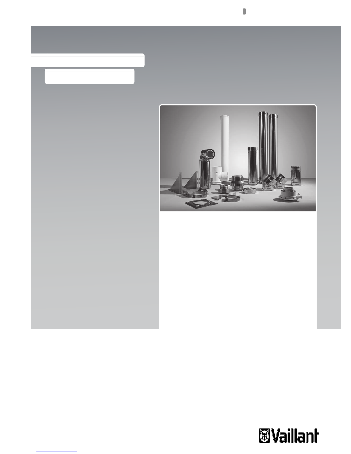
Air/flue gas system
VKK ../3
GB

Legal information
Document type: Installation manual
Product: Air/flue gas system
– 130 mm diameter system
– 160 mm diameter system
– 200 mm diameter system
Target group: Authorised competent person
Language: EN
Document number_version: 0020058722_04
Created on: 26.09.2012
Publisher/manufacturer
Vaillant GmbH
Berghauser Str. 40 D-42859 Remscheid
Telefon +49 21 91 18‑0 Telefax +49 21 91 18‑28 10
info@vaillant.de www.vaillant.de
© Vaillant GmbH 2012
These instructions, or extracts thereof, may only be printed with the written consent of Vaillant GmbH.
All designations of products in these instructions are brand names/trade marks of the companies in question.
We reserve the right to make technical changes.

Contents
1 Notes on the documentation .............................. 4
1.1 Observing other applicable documents ................. 4
1.2 Storing documents................................................. 4
1.3 Applicability of the instructions .............................. 4
2 Safety .................................................................... 5
2.1 Action-related warnings ......................................... 5
2.2 Required personnel qualifications ......................... 5
2.3 General safety information .................................... 5
2.4 Intended use .......................................................... 7
2.5 Regulations (directives, laws, standards) .............. 8
3 System overview.................................................. 9
3.1 Combination options for systems with VKK........... 9
3.2 130 mm diameter system ...................................... 9
3.3 160 mm diameter, 200 mm diameter system ........ 9
4 Certified air/flue gas systems and
components ....................................................... 11
4.1 Certified air/flue gas systems and components,
130 mm diameter................................................. 11
4.2 Certified air/flue gas systems and components,
160 mm diameter................................................. 11
4.3 Certified air/flue gas systems and components,
200 mm diameter................................................. 11
4.4 Certified flue gas systems.................................... 12
5 System conditions............................................. 12
5.1 Maximum pipe lengths......................................... 12
5.2 General installation instructions........................... 17
6 Installing the 130 mm diameter system........... 18
6.1 Installation instructions ........................................ 18
6.2 Installing the basic set for shaft installation ......... 19
6.3 Flue gas connection and installing the
horizontal flue gas pipe........................................ 20
6.4 Installing the combustion air line ......................... 21
7 Installing the 160 mm diameter and 200 mm
diameter systems .............................................. 22
7.1 Installing the flue gas pipe in the shaft ................ 22
7.2 Installing a flue gas pipe on a support pipe
(optional).............................................................. 25
7.3 Installing the vertical roof duct ............................. 25
7.4 Installing the flue gas pipe on the external
wall....................................................................... 26
7.5 Stabilising the flue gas pipe ................................. 30
7.6 Flue gas connection and installing the
horizontal flue gas pipe........................................ 31
7.7 Installing the combustion air line ......................... 31
8 Customer service............................................... 32
Index ................................................................................... 33
Contents
0020058722_04 Air/flue gas system Installation manual 3

1 Notes on the documentation
1 Notes on the documentation
1.1 Observing other applicable documents
For the competent person:
– Installation instructions for the installed Vaillant product.
1.2 Storing documents
▶ Pass these instructions and all other applicable docu-
ments on to the system operator.
The system operator should retain these instructions for further use.
1.3 Applicability of the instructions
These instructions apply only for the Vaillant heat generator
named in the other applicable documents and referred to as
the "product" in this document.
4 Installation manual Air/flue gas system 0020058722_04
Safety 2
5mm
15°
2 Safety
2.1 Action-related warnings
Classification of action-related warnings
The action-related warnings are classified in accordance
with the severity of the possible danger using the following
warning signs and signal words:
Warning symbols and signal words
Danger!
Imminent danger to life or risk of severe personal
injury
Danger!
Risk of death from electric shock
Warning.
Risk of minor personal injury
Caution.
Risk of material or environmental damage
2.2 Required personnel qualifications
These instructions are intended for the competent person.
▶ As part of the annual maintenance, inspect the flue gas
system in terms of:
– external faults such as brittleness and damage
– safe pipe connections and secure fastenings
2.3.3 Risk of death from leaks in the flue gas
route
Flue gas may escape from leaking pipes or damaged seals.
Mineral-oil-based greases can damage the seals.
▶ Transport the pipes to the installation site only in the ori-
ginal packaging.
▶ If the temperature is lower than 0 °C, warm the pipes
before beginning installation.
▶ When installing the flue gas installation, use only flue
pipes of the same material.
▶ Do not install any damaged pipes.
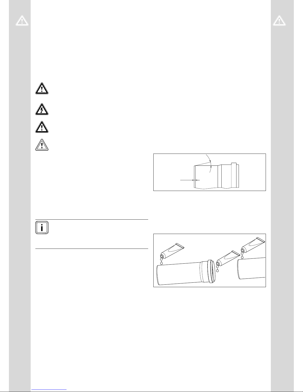
▶ When connecting, always slide the pipes into the sleeve
until they reach a stop.
▶ Shorten the flue pipes to the suitable lengths at right
angles along their smooth side.
2.2.1 Authorised competent person
The installation, assembly and removal, start-up, maintenance, repair and decommissioning of Vaillant products and
accessories must only be carried out by authorised competent persons.
Note
Each competent person is qualified for specific
activities on the basis of their training. They must
only work on units if they have the required qualification.
When working on the units, the competent persons must
observe all applicable directives, standards, laws and other
regulations.
2.3 General safety information
2.3.1 Informing the responsible departments
▶ Before installing the flue pipe, inform the local gas supply
company and the district master chimney sweep.
2.3.2 Risk of poisoning due to escaping flue gas
Improperly installed flue gas pipes may cause flue gas to
escape.
▶ Before starting up the product, check that the whole flue
pipe is securely fastened and sealed.
▶ File off sharp burrs and chamfer the ends of the pipes be-
fore assembling them so that the seals are not damaged,
and dispose of the shavings.
▶ Never use mineral-oil-based grease for the installation.
▶ Only 130 mm diameter systems: if necessary, only use
water to facilitate installation.
▶ Only 160 mm diameter and 200 mm diameter systems:
Use the lubricant supplied to facilitate installation.
The flue gas pipe may become damaged by unforeseeable
external influences.
0020058722_04 Air/flue gas system Installation manual 5

2 Safety
1
2
▶ When fitting the flue pipes, make absolutely sure the
seals are correctly positioned. The lip of the seal must
be facing inwards (1), not outwards (2).
▶ Do not use any damaged seals.
Mortar residues, shavings, etc. in the flue pipe may restrict
the outward flow of the flue gas. Flue gas may escape into
the room.
▶ After installation, remove all mortar residues, shavings,
etc. from the flue pipe.
Extensions that are not secured to the wall or ceiling may
bend and separate due to thermal expansion.
▶ Secure each extension to the wall or ceiling using a pipe
clamp.
▶ Where possible, use the original pipe clamps from the
product range.
– If you are using standard pipe clamps, the tension-
ing range must be between 130 mm, 160 mm and
200 mm, and the bearing capacity must be at least
200 kg.
– The distance between two pipe clamps must not be
greater than the length of the extension.
– The pipe clamps must be isolated from structure-
borne sound.
– Downward gradient to the product: 3°
Note
3° corresponds to a downward gradient of
approx. 50 mm per metre of pipe length.
2.3.4 Risk of death from flue gas escaping from
openings in the flue pipe
All openings in the flue pipe that can be opened for inspection purposes must be closed before start-up and during operation.
▶ The openings of the flue pipe must only be opened by a
competent person.
2.3.5 Risk of fire and electronic damage caused
by missing lightning protection for the flue
gas installation
The product may be damaged by the effects of lightning and
this may lead to fires.
▶ If the building is equipped with a lightning protection sys-
tem, incorporate the air/flue gas pipe into the lightning
protection.
▶ If the vertical flue gas pipe contains materials made from
metal, incorporate it into the potential balancing system.
2.3.6 Risk of injury from snow falling from roofs
Where flue pipes penetrate the roof skin, the water vapour
contained in flue gas may precipitate as ice on the roof or the
roof structures in unfavourable weather conditions.
▶ At the installation site, ensure that this ice build-up does
not slide from the roof.
▶ If necessary, install an ice collection mesh.
The flue gas pipe expands when warm. If the pipes are obstructed when expanding, this may lead to a forced fracture
and flue gases will escape.
▶ Secure each of the pipe clamps to the wall or the ceiling
using a hanger bolt or threaded bolt M8/M10. This allows
for sufficient elasticity of the fastening in the event of
thermal expansion of the pipes.
▶ Secure the pipe clamps using hanger bolts or stud bolts.
Loads on the flue gas guiding may damage the flue gas pipe
and lead to flue gas escaping.
▶ Do not secure any loads to the flue gas guiding.
Mechanical impact loading of the flue gas pipe may damage
the flue gas pipe. Flue gases may escape.
▶ Do not install the flue gas pipe in areas with mechanical
impact loading. The flue gas pipe can also be protected
against impact using protection devices that are created
on-site.
Standing condensate can damage the seals of the flue gas
pipe.
▶ Route the horizontal flue pipe with a downward gradient.
6 Installation manual Air/flue gas system 0020058722_04
2.3.7 Risk of suffocation from lack of rear
ventilation
The flue gas pipe is not ventilated from behind.
If the installation room for the product is not ventilated, there
is a risk of suffocation.
▶ In the installation room, build a ventilation opening that
leads outside.
– Cross-sectional area: 150 cm²
2.3.8 Risk of corrosion in the flue gas installation
Sprays, solvents, cleaning agents, paints and adhesives may
contain substances that could lead to corrosion in the flue
gas installation in some circumstances when the product is
in operation.
▶ Ensure that the combustion air that is guided to the
product is kept free of chemical substances that may
contain fluorine, chlorine, or sulphur, for example.
▶ Only use appropriate Vaillant components for installing
the flue gas guiding.
Safety 2
2.3.9 Inspect/clean chimneys to which former
solid fuel boilers were once connected
We recommend that you have chimneys inspected and
cleaned by a chimney sweep before the flue gas pipe is
installed if these chimneys were previously used to divert
flue gas away from solid-fuel-fired boilers but should now
supply combustion air. If it is not possible to adequately inspect/clean the chimney (e. g. due to construction features),
you can
– use a separate air supply or
– use open-flued operation for the system.
2.3.10 Risk of corrosion in the product caused by
using a chimney to which the former oilfired boiler was once connected
Chimneys that previously diverted the flue gas away from oilfired boilers should not be used to supply combustion air.
The combustion air may be charged with chemical deposits
and this leads to corrosion in the product.
2.3.11 Risk of fire due to insufficient clearance
▶ Ensure that the flue gas pipe outside the shaft has a min-
imum clearance of 5 cm from flammable components.
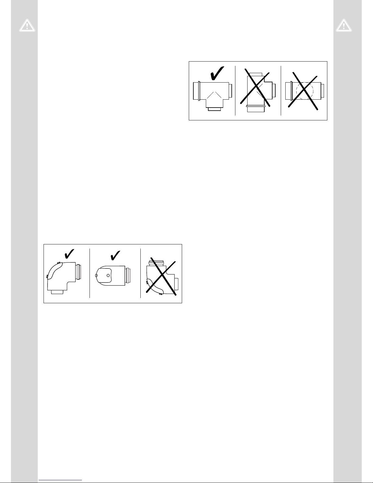
2.3.12 Moisture damage caused by incorrect
installation location of the inspection elbow
An incorrect installation location leads to condensate leaking
from the lid of the opening for cleaning and may lead to corrosion damage.
▶ Install the inspection elbow in accordance with the illus-
tration.
2.3.13 Moisture damage caused by incorrect
installation location of the inspection Tpiece
An incorrect installation location leads to condensate leaking
from the lid of the opening for cleaning and may lead to corrosion damage.
▶ Install the inspection T-piece in accordance with the illus-
tration.
2.3.14 Material damage due to improper use
and/or unsuitable tools
Improper use and/or the use of unsuitable tools may result in
material damage.
▶ Always use a suitable open-end spanner to tighten or
undo threaded connections.
▶ Do not use pipe wrenches, extensions, etc.
2.4 Intended use
2.4.1 Intended use of the Vaillant air/flue gas
systems
Vaillant air/flue gas systems are constructed using state-ofthe-art technology in accordance with the recognised safety
rules and regulations. Nevertheless, there is still a risk of
injury or death to the system operator or others or of damage
to the products and other property in the event of improper
use or use for which the products are not intended.
The Vaillant air/flue gas systems named in this manual must
only be used in combination with the product types named in
this manual.
Any other use that is not specified in these instructions, or
use beyond that specified in this document, shall be considered improper use.
Intended use includes the following:
– observance of accompanying operating, installation and
servicing instructions for the Vaillant product as well as
for all other components of the system
– installing and fitting the product in accordance with the
product and system approval
– compliance with all inspection and maintenance condi-
tions listed in the instructions.
0020058722_04 Air/flue gas system Installation manual 7
2.4.2 CE certification
The products are certified as boiler systems with attached
flue gas installation according to the EU gas appliances directive 90/396/EEC or 2009/142/EC.

2 Safety
This installation manual is a component of the certification
and is cited in the type testing certificate. In compliance
with the regulatory statutes of this installation manual, the
proof of usability of the products identified by Vaillant article
numbers that are designed for the flue pipe is provided. If
you do not use certified elements for the Vaillant flue pipe
when installing the products, this voids the CE conformity of
the product. We therefore strongly recommend that you fit
Vaillant air/flue gas systems.
2.5 Regulations (directives, laws, standards)
Please observe the existing national rules and regulations,
standards, laws and guidelines.
8 Installation manual Air/flue gas system 0020058722_04
System overview 3
3 System overview
Observe the maximum pipe lengths, see "Maximum pipe
lengths" (→ Page 12).
3.1 Combination options for systems with VKK
130 mm diameter 160 mm diameter 200 mm diameter
VKK 806/3-E-HL
VKK 1206/3-E-HL
VKK 1606/3-E-HL
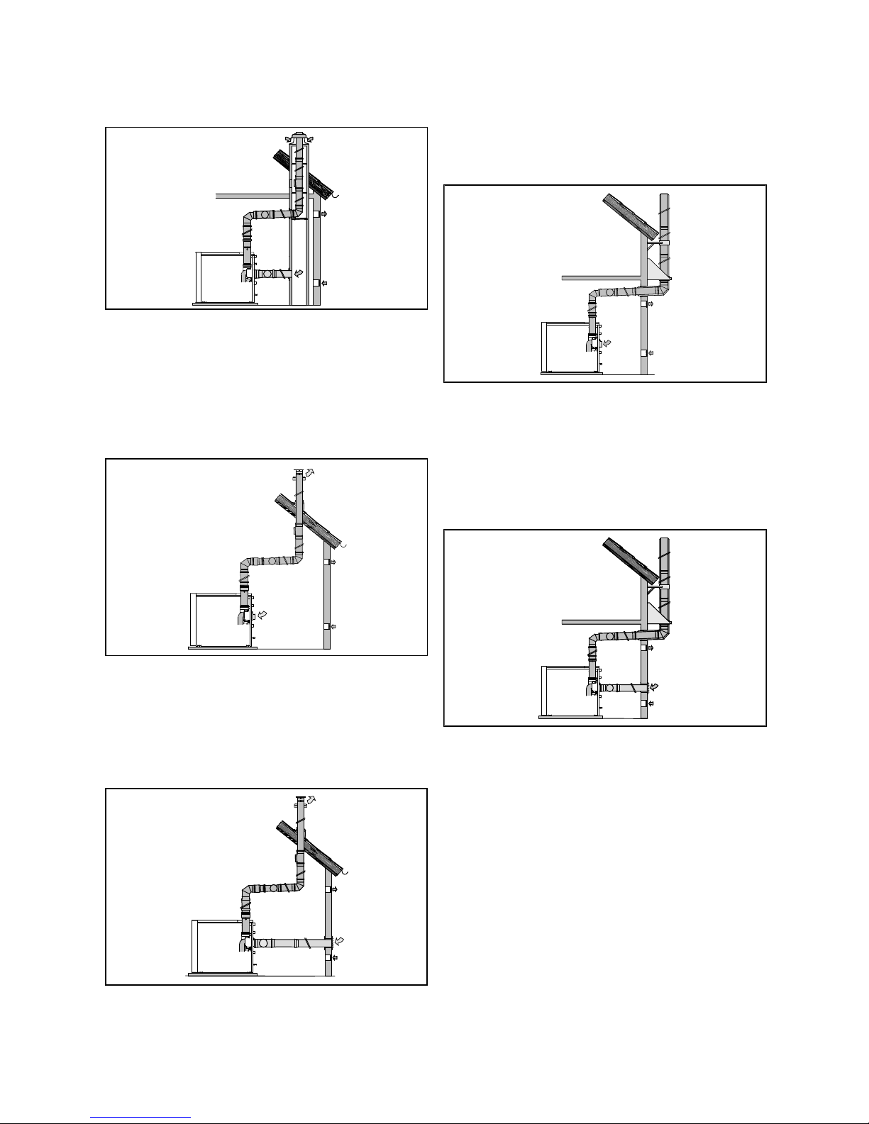
3.2 130 mm diameter system
3.2.1 Flue gas pipe in the shaft, combustion air
from the installation room
VKK 806/3-E-HL
VKK 1206/3-E-HL
VKK 1606/3-E-HL
VKK 2006/3-E-HL
VKK 2406/3-E-HL
VKK 2806/3-E-HL
3.2.3 Flue gas pipe in the shaft, combustion air
from the shaft
▶ Installing the 130 mm diameter system (→ Page 18)
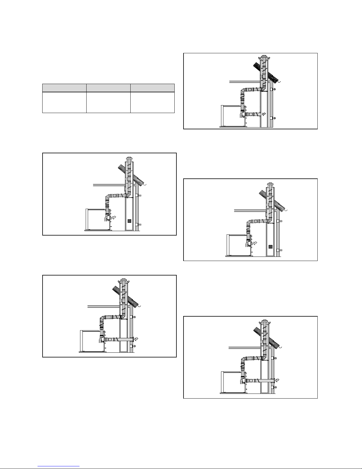
3.3 160 mm diameter, 200 mm diameter system
3.3.1 Flue gas pipe in the shaft, combustion air
from the installation room
▶ Installing the 130 mm diameter system (→ Page 18)
3.2.2 Flue gas pipe in the shaft, combustion air
through the external wall
▶ Installing the 130 mm diameter system (→ Page 18)
▶ Installing the flue gas pipe in the shaft (→ Page 22)
▶ Flue gas connection and installing the horizontal flue gas
pipe (→ Page 31)
3.3.2 Flue gas pipe in the shaft, combustion air
through the external wall
▶ Installing the flue gas pipe in the shaft (→ Page 22)
▶ Installing the combustion air line in the external wall
(→ Page 31)
▶ Flue gas connection and installing the horizontal flue gas
pipe (→ Page 31)
0020058722_04 Air/flue gas system Installation manual 9
3 System overview
3.3.3 Flue gas pipe in the shaft, combustion air
from the shaft
▶ Installing the flue gas pipe in the shaft (→ Page 22)
▶ Installing the combustion air line in the shaft (→ Page 31)
▶ Flue gas connection and installing the horizontal flue gas
pipe (→ Page 31)
3.3.4 Flue gas pipe through the roof, combustion
air from the installation room
▶ Flue gas connection and installing the horizontal flue gas
pipe (→ Page 31)
3.3.6 Flue gas pipe on the external wall,
combustion air from the installation room
1. Installing the flue gas pipe on the external wall
(→ Page 26)
2. Flue gas connection and installing the horizontal flue
gas pipe (→ Page 31)
3.3.7 Flue gas pipe on the external wall,
combustion air through the external wall
▶ Installing the roof duct (→ Page 26)
▶ Flue gas connection and installing the horizontal flue gas
pipe (→ Page 31)
3.3.5 Flue gas pipe through the roof, combustion
air through the external wall
▶ Installing the roof duct (→ Page 26)
▶ Installing the combustion air line in the external wall
(→ Page 31)
▶ Installing the flue gas pipe on the external wall
(→ Page 26)
▶ Installing the combustion air line in the external wall
(→ Page 31)
▶ Flue gas connection and installing the horizontal flue gas
pipe (→ Page 31)
10 Installation manual Air/flue gas system 0020058722_04
Certified air/flue gas systems and components 4
4 Certified air/flue gas systems and
components
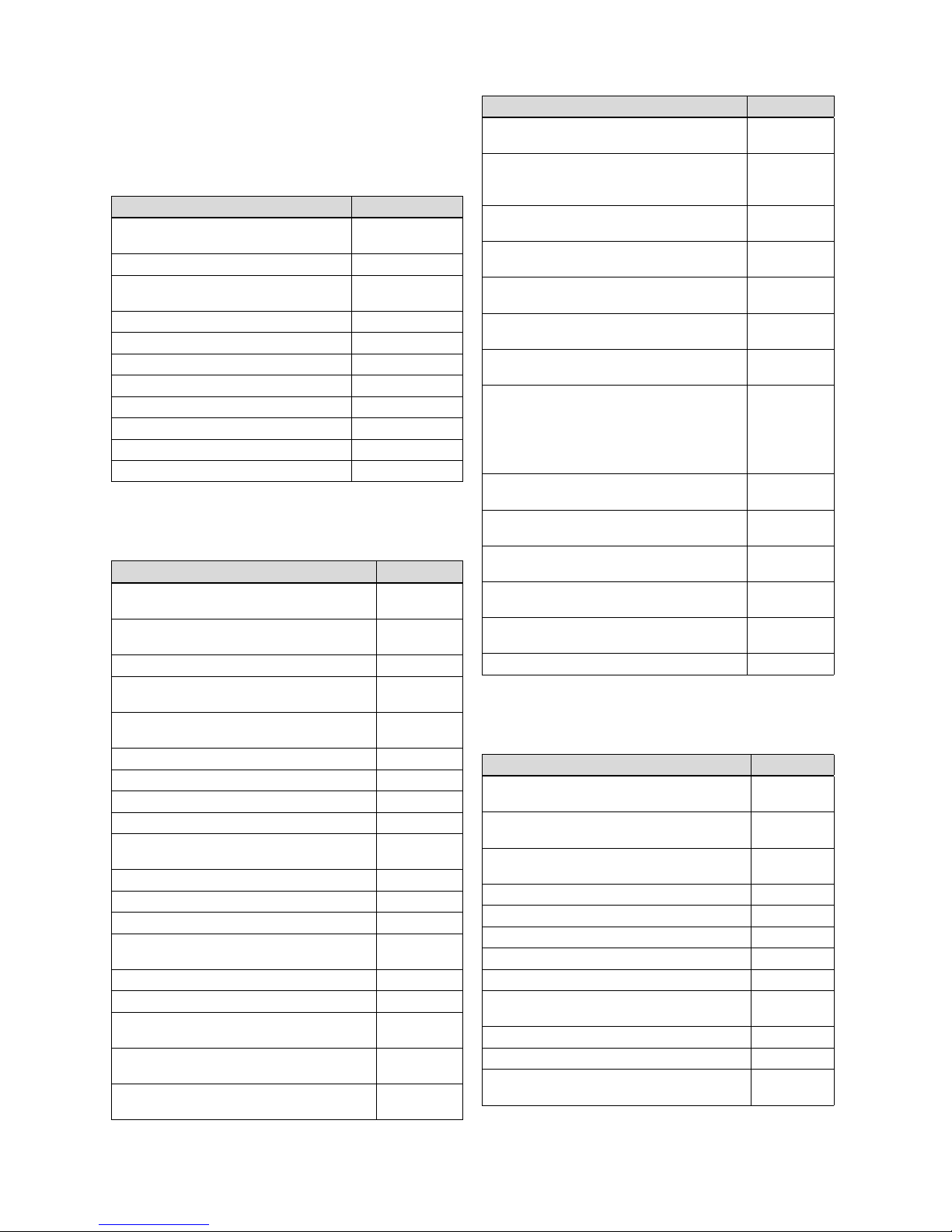
4.1 Certified air/flue gas systems and
components, 130 mm diameter
Components Art. no.
Basic set for shaft installation (PP),
130 mm diameter
Spacer (PP), 7 pcs, 130 mm diameter 0020042763
Inspection opening with cover (PP),
130 mm diameter
87° elbow (PP), 130 mm diameter 0020042765
45° elbow (PP), 130 mm diameter 0020042766
30° elbow (PP), 130 mm diameter 0020042767
15° elbow (PP), 2 pcs, 130 mm diameter 0020042768
Extension (PP), 1.0 m, 130 mm diameter 0020042769
Extension (PP), 2.0 m, 130 mm diameter 0020042770
Extension (PP), 0.5 m, 150 mm diameter 0020095543
Basic set for air intake, 130 mm diameter 0020060591
4.2 Certified air/flue gas systems and
components, 160 mm diameter
Components Art. no.
Unit connection (PP) with measurement opening, 150 – 160 mm diameter
Basic set for shaft installation (PP), 160 mm
diameter
Set for air intake (PP), 160 mm diameter 0020095535
End pipe (stainless steel), 0.5 m, 160 mm diameter
Installation aid with a line loop, 160 mm diameter
Extension (PP), 0.5 m, 160 mm diameter 0020095545
Extension (PP), 1.0 m, 160 mm diameter 0020095546
Extension (PP), 2.0 m, 160 mm diameter 0020095547
87° elbow (PP), 160 mm diameter 0020095552
87° elbow (PP) with inspection opening,
160 mm diameter
45° elbow (PP), 160 mm diameter 0020095556
30° elbow (PP), 160 mm diameter 0020095558
15° elbow (PP), 160 mm diameter 0020095560
Inspection element (PP) 0.21 m, 160 mm diameter
Spacer (1 pc), 160 mm diameter 0020095563
Spacer (4 pcs), 160 mm diameter 0020095565
Vertical roof duct (PP), concentric, 160/186 mm
diameter
Universal pitched roof tile (25° - 45°), black, for
roof duct, 160/186 mm diameter
Universal pitched roof tile (25° - 45°), red, for
roof duct, 160/186 mm diameter
0020042762
0020042764
0020095531
0020095533
0020095537
0020095541
0020095554
0020095561
0020095567
0020095568
0020095569
Components Art. no.
Flat roof penetration collar (aluminium), for the
roof duct, 160/186 mm diameter
External wall connection (stainless steel), elbow,
support console, external collar, 160/225 mm
diameter
External wall pipe bracket (stainless steel),
225 mm diameter
Extension (stainless steel) for external wall
laying, 0.5 m, concentric, 160/225 mm diameter
Extension (stainless steel) for external wall
laying, 1.0 m, concentric 160/225 mm diameter
Vertical roof duct (stainless steel) for external
wall laying, concentric, 160/225 mm diameter
Opening piece (stainless steel), 160/225 mm
diameter
Tile for pitched roof for 160/225 mm diameter
system, dependent on the angle
15° - 25°
25° - 35°
35° - 45°
Flat roof penetration collar (stainless steel) for
160/225 mm diameter system, stainless steel
Inspection element (stainless steel), 0.4 m,
160/225 mm diameter
Support elbow mounting rail, long version, 500mm0020095539
Air clamp (stainless steel) for 160/225 mm
diameter
45° elbow (stainless steel) for external wall
laying, concentric, 160/225 mm diameter
Fastening clamp, 160 mm diameter 0020151162
0020095570
0020095573
0020095575
0020095577
0020095579
0020095581
0020095583
0020095585
0020130600
0020130601
0020095587
0020095589
0020095540
0020095544
4.3 Certified air/flue gas systems and
components, 200 mm diameter
Components Art. no.
Unit connection (PP) with measurement opening,
200 mm diameter
Basic set for shaft installation (PP), 200 mm
diameter
End pipe (stainless steel), 0.5 m, 200 mm diameter
Installation aid with line loop, 200 mm diameter 0020095542
Extension (PP), 0.5 m, 200 mm diameter 0020095549
Extension (PP), 1.0 m, 200 mm diameter 0020095550
Extension (PP), 2.0 m, 200 mm diameter 0020095551
87° elbow (PP), 200 mm diameter 0020095553
87° elbow (PP) with inspection opening, 200 mm
diameter
45° elbow (PP), 200 mm diameter 0020095557
30° elbow (PP), 200 mm diameter 0020095559
Inspection element (PP), 0.5 m, 200 mm diameter
0020095532
0020095534
0020095538
0020095555
0020095562
0020058722_04 Air/flue gas system Installation manual 11
 Loading...