

Page 1
For the competent person
Installation Manual
Installation Manual
Air/Flue Gas System for
ecoTEC
GB, IE
Page 2

Contents
Contents
1 Notes on the documentation .....................................3
1.1 Storing documents ..........................................................3
1.2 Symbols used ....................................................................3
1.3 Applicability of the instructions ...................................3
1.4 Air/flue gas systems available ......................................3
2 Safety .................................................................................4
2.1 Safety and warning information ..................................4
2.1.1 Classification of warnings ..............................................4
2.1.2 Structure of warnings .....................................................4
2.2 General safety information ............................................4
2.3 Regulations ........................................................................5
2.4 Intended use ......................................................................5
2.5 Certified air/flue gas systems .......................................5
3 Concentric system (standard), dia. 60/100 .......... 6
3.1 Product range ...................................................................6
3.2 Maximum permissible pipe lengths ........................... 10
3.2.1 Maximum permitted pipe lengths for
ecoTEC exclusive ..............................................................11
3.2.2 Maximum permitted pipe lengths for ecoTEC ..........11
3.3 Fitting the sliding sleeve ...............................................12
3.4 Fitting the horizontal wall penetration ......................12
3.4.1 Scope of delivery ............................................................13
3.4.2 Preparing for installation ..............................................13
3.5 Fitting the telescopic horizontal air/flue pipe ..........15
3.5.1 Scope of delivery ............................................................15
3.5.2 Preparations .....................................................................16
3.6 Fitting the black terminal kit ........................................17
3.6.1 Scope of delivery ............................................................17
3.6.2 Assembling the black terminal kit before fitting
the flue pipe .....................................................................17
3.6.3 Fitting the black terminal kit after fitting the
flue pipe............................................................................ 18
3.7 Fitting the variable terminal kit (VTK).......................19
3.7.1 Scope of delivery ............................................................19
3.7.2 Assembling the variable terminal kit before
fitting the flue pipe .........................................................19
3.7.3 Fitting the variable terminal kit after fitting
the flue pipe .....................................................................21
3.7.4 Fitting extensions...........................................................22
3.7.5 Fitting variable terminal kit extensions around
roof overhangs ...............................................................24
3.8 Fitting the deflector set ...............................................24
3.8.1 Scope of delivery ...........................................................24
3.8.2 Fitting the deflector set before fitting the flue
pipe ....................................................................................24
3.8.3 Fitting the deflector set after fitting the flue
pipe ....................................................................................25
3.8.4 Fitting the variable terminal kit after fitting
the flue pipe ....................................................................26
3.9 Fitting the vertical roof penetration .........................27
3.9.1 Scope of delivery ...........................................................27
3.9.2 Preparations ....................................................................27
3.9.3 Fitting the pitched-roof penetration .........................28
3.9.4 Fitting the flat-roof penetration .................................29
3.10 Fitting ridge tiles ........................................................... 30
3.10.1 Scope of delivery .......................................................... 30
3.10.2 Preparations ................................................................... 30
3.10.3 Fitting the ridge tile ..................................................... 30
3.10.4 Fitting the ridge-tile terminal ......................................31
3.11 Fitting concentric connector to a chimney
air/flue pipe .....................................................................32
3.11.1 Components suitable for connection ........................32
3.11.2 Installation example ......................................................32
3.11.3 Installing the boiler ........................................................33
3.12 Fitting extensions and elbows ................................... 34
3.12.1 Fitting extensions.......................................................... 34
3.12.2 Fitting two 87° elbows ..................................................35
3.12.3 Fitting 87° elbows ..........................................................37
3.12.4 Fitting 45° elbows......................................................... 38
4 Concentric system (optional), dia. 80/125 .........39
4.1 Product range .................................................................39
4.2 Maximum permissible pipe lengths ............................41
4.2.1 Maximum permitted pipe lengths for
ecoTEC exclusive ........................................................... 42
4.2.2 Maximum permitted pipe lengths for ecoTEC ....... 42
4.3 Replacing the boiler flue connection ....................... 43
4.3.1 Replacing the boiler flue connection on
ecoTEC exclusive and ecoTEC plus open vented .. 43
4.3.2 Replacing the boiler flue connection on
ecoTEC plus and ecoTEC pro ..................................... 43
4.4 Fitting the sliding sleeve ............................................. 44
4.5 Fitting the horizontal air/flue pipe ...........................44
4.5.1 Scope of delivery .......................................................... 44
4.5.2 Preparations ................................................................... 45
4.5.3 Fitting with side flue exit ............................................ 45
4.5.4 Installing the boiler with gap from external wall ...47
4.6 Fitting the vertical air/flue pipe ................................48
4.6.1 Scope of delivery .......................................................... 48
4.6.2 Preparing for installation ............................................ 48
4.6.3 Fitting the pitched-roof penetration ........................ 48
4.6.4 Fitting the flat-roof penetration ................................ 49
4.7 Fitting extensions and elbows ...................................50
4.7.1 Fitting extensions..........................................................50
4.7.2 Fitting two 87° elbows ...................................................51
4.7.3 Fitting 87° elbows ..........................................................53
4.7.4 Fitting 45° elbows......................................................... 54
5 Vaillant Service ............................................................ 55
Index .......................................................................................... 56
2 Installation Manual air/flue gas system for ecoTEC 834449_16
Page 3

Notes on the documentation
1
1 Notes on the documentation
The following instructions are intended to guide you
throughout the entire documentation. Other documents
apply in addition to these installation instructions. We
accept no liability for any damage caused by non-observance of these instructions.
Other applicable documents
For the competent person:
– Installation instructions for installed gas-fired wall hung
high-efficiency boiler.
1.1 Storing documents
> Please pass on this installation manual, all other applica-
ble documents and any additional aids required to the
system operator.
The system operator will take responsibility for keeping
them safe so that they are available when required.
1.2 Symbols used
The symbols used in this document are explained below.
Symbol that denotes danger:
– Imminent danger to life
a
– Risk of severe personal injury
– Risk of minor personal injury
1.4 Air/flue gas systems available
There are two types of air/flue gas system available for the
ecoTEC gas-fired wall-hung boilers:
– Concentric air/flue gas systems (standard) (external
diameter 100 mm)
– Concentric air/flue gas system (optional) with larger
diameter (external diameter 125 mm) which allows longer
air/flue pipe systems to be constructed.
Symbol that denotes danger:
– Risk of death from electric shock
e
Symbol that denotes danger:
– Risk of material damage
b
– Risk of damage to the environment
Symbol that denotes useful tips and information
i
> Symbol for a required action
1.3 Applicability of the instructions
This Installation Manual applies exclusively to the Vaillant
appliances specified in the other applicable documents.
Installation Manual air/flue gas system for ecoTEC 834449_16 3
Page 4
a
2
Safety
a
2 Safety
2.1 Safety and warning information
When installing the systems, observe the general safety
instructions and warnings which appear before the instructions for each operation.
2.1.1 Classification of warnings
The warnings are classified according to the severity of the
potential danger using the following danger signs and signal words:
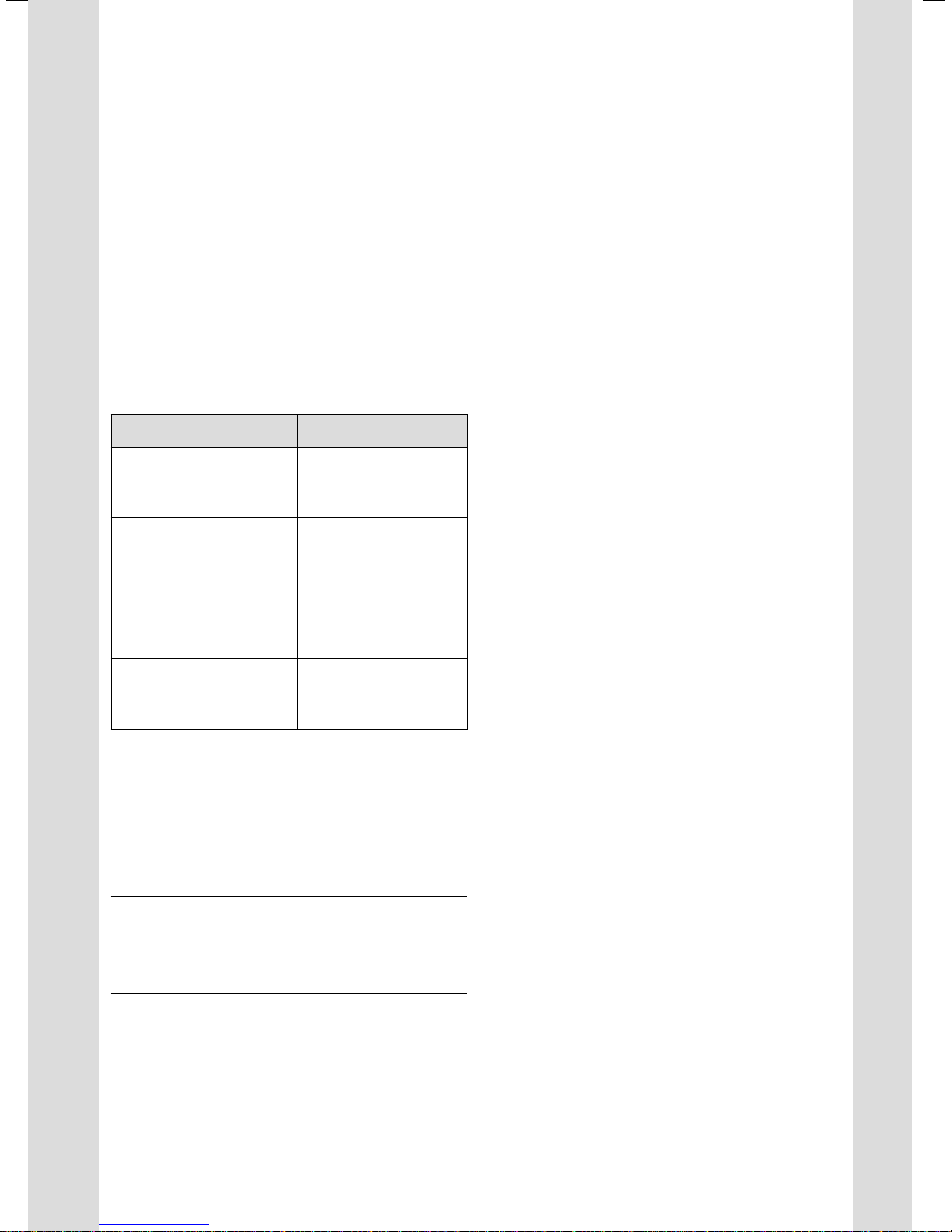
Danger sign Signal word Explanation
Immediate risk of death or
Danger!
a
Danger!
e
Warning.
a
Caution.
b
2.1 Meaning of danger signs and signal words
risk of severe personal
injury
Risk of death from electric
shock
Risk of minor personal
injury
Risk of material or environmental damage
Qualification of technical staff
The installation of the boiler and its flue must be carried
out by a competent person approved at the time by the
Health and Safety Executive.
> Furthermore, the requirements, rules and regulations
specified in the installation instructions for the appliances must be followed.
Risk of fatal poisoning from escaping flue gases
All openings in the flue ducting that can be opened for
inspection purposes must be closed before commissioning
and while the system is in operation.
> Make sure that the openings in the flue duct system are
only opened by a competent person.
Flue gas can escape from leaking pipes or damaged seals.
> When installing the flue system, use only flue pipes of
the same material.
Mineral oil-based lubricants may damage the seals.
> On no account should mineral-oil based grease be used
for installation.
> Only use water or commercially available soft soap, if
necessary, to assist with installation.
Mortar residues, shavings, etc. in the flue ducts can restrict
the outward flow of the flue gas. Flue gas may escape into
the room.
> After installation, remove all mortar residues, shavings,
etc. from the flue ducts.
Extensions that are not fixed to a wall or ceiling may
become disconnected due to sagging or thermal expansion.
> Ensure that every extension is fixed to the wall or ceiling
by means of a pipe bracket. The distance between two
pipe brackets must not be greater than the length of the
extension.
2.1.2 Structure of warnings
Warnings signs are identified by an upper and lower separating line and are laid out according to the following basic
principle:
Signal word!
Type and source of danger!
a
2.2 General safety information
> Observe the following safety instructions and require-
ments at all times.
4 Installation Manual air/flue gas system for ecoTEC 834449_16
Explanation of the type and source of
danger.
> Measures for averting the danger.
Unsecured joints on the air/flue gas ducting may become
disconnected.
> Secure each air-pipe joint by screwing the air-pipe collars
with the air-pipe ends or the boiler flue connection.
Condensate that collects in a particular place can damage
the flue pipe seals.
> Install a horizontal flue pipe with a gradient of 3° 1°
sloping downwards to the appliance. That equates to a
drop of approx. 50 mm 20 mm per metre of pipe run.
Requirements for the air/flue pipe outlet
> Observe the requirements for the air/flue pipe outlet
specified in the installation instructions for the boiler.
Fire risk from lightning strike
> Make sure that the flue system is incorporated in the
building's lightning conductor circuit if the building has
one.
Page 5

a
Safety
2
a
Risk of corrosion in the flue system
Sprays, solvents or cleaning agents, paints and adhesives
may contain substances which, if the boiler is operating
under the most unfavourable conditions, can cause corrosion in the flue system.
> Use only the appropriate Vaillant components when
installing the flue system.
> Keep the combustion air that is drawn into the boiler
free of chemicals that contain substances such as fluo-
rine, chlorine or sulphur.
Use of tools
Unsuitable tools and/or improper use of tools can cause
damage (e.g. to casing panels or system components).
Always use screwdrivers and spanners (open-ended) of the
correct size when undoing or tightening screws, nuts and
bolts. Do not use pipe wrenches, extensions, etc.
Distance from adjacent components
The air/flue pipe operates at a very low temperature, which
means that there is no minimum clearance required
between the air pipe and adjacent supply lines.
2.3 Regulations
Installation of the gas-fired wall-hung boiler and its air/flue
pipe must conform to the Gas Safety Regulations (Installation and Use) 1998, the Building Regulations and BS 5440
Part 1.
2.5 Certified air/flue gas systems
The Vaillant ecoTEC gas-fired wall-hung boilers are certified
in accordance with the EC Gas Appliance Directive 90/396/
EEC or 2009/142/EC as heating boiler systems with associated flue systems. This Installation Manual is a component
of the certification and is cited in the type approval certificate. Subject to compliance with the requirements for carrying out installation set out in this Installation Manual, the
usability of the air/flue pipe system products identified by
Vaillant article numbers is certified.
Danger!
Vaillant appliances are certified only for
a
use with genuine Vaillant flue pipes.
Malfunctions can occur if you use other
accessories. These may result in damage
and injury. You will find a list of genuine
flue pipes in the Vaillant installation manual
for flue pipes. The CE mark is valid only if
the appliance is operated with Vaillant flue
pipes.
> Only use genuine
Vaillant flue pipes.
2.4 Intended use
Vaillant air/flue pipe systems are constructed using stateof-the-art technology in accordance with recognised safety
regulations. Nevertheless, there is still a risk of injury or
death to the system operator or others or of damage to the
products and other property in the event of improper use
or use for which the products are not intended.
The Vaillant air/flue pipe systems described in this manual
may only be used in conjunction with the appliance types
specified in this manual.
Any use other than or beyond that specified constitutes
improper use and nullifies any responsibility or liability
whatsoever on the part of the manufacturer/supplier for
resulting loss or damage. In such cases, the risk is borne
solely by the person carrying out the work and the
user.
Intended use includes the following:
– observing the operating, installation and maintenance
instructions supplied for the Vaillant product and any
other parts and components of the system
– installing and fitting the product in accordance with the
appliance and system approval
– complying with all of the inspection and maintenance
conditions listed in the instructions.
Installation Manual air/flue gas system for ecoTEC 834449_16 5
Page 6

Concentric system (standard), dia. 60/100
3
3 Concentric system (standard),
dia. 60/100
The air pipes are made of galvanised steel, the flue pipes
out of plastic.
3.1 Product range
0020060570 = Vertical air/flue pipe
0020065937 = Vertical air/flue pipe
303982 = Ridge tile terminal
303933 = Horizontal air/flue pipe
303936 = Horizontal telescopic air/flue pipe
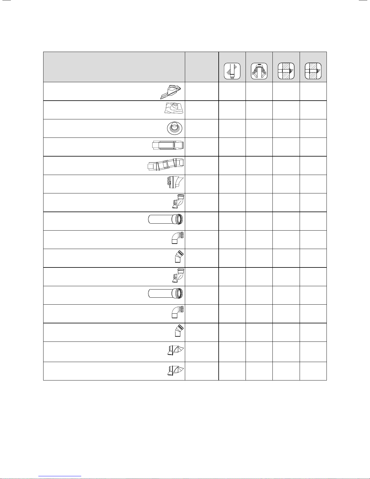
Optional accessories Art. no.
Extensions, concentric
470 mm - dia. 60/100
Extensions, concentric
970 mm - dia. 60/100
Extensions, concentric
1970 mm - dia. 60/100
Extensions, concentric
1970 mm - dia. 60/100
(black, RAL 9005)
(black, RAL 9005)
303902 X X X X
303903 X X X X
303905 X X X X
1)
0020138174 X X X X
0020060570
0020065937
303982 303933 303936
Elbows (PP), concentric (set of 2)
45° - dia. 60/100
Elbow, concentric
87° - dia. 60/100
Pipe brackets for flue pipe (set of 5), dia. 100
Adjustable pipe brackets for flue pipe
(set of 3); dia. 100
Sliding sleeve (PP), dia. 60/100
1) In order to assist with longer flues within buildings with the minimum number of joints to be inspected a 4 metre air/flue duct extension will available - by special order only.
(special delivery requirements along with a minimum order quantity and a no returns policy will apply).
Note that the fall angle remains as with all other vaillant flues - so a 4 m length would require a total fall of 200mm. This must be
taken into account when deciding upon the location of the boiler.
3.1 Product range
6 Installation Manual air/flue gas system for ecoTEC 834449_16
303911 X X X X
303910 X X X X
303821 X X X X
303935 X X X X
303915 X X X X
Page 7
Concentric system (standard), dia. 60/100
3
Optional accessories Art. no.
Roof flashing plate for pitched roof
009076 (black) X
Universal flashing plate, pitched roof
303980 X
Flat roof flashing
009056 X
Telescopic extension
440 - 690 mm - dia. 60/100
Telescopic offset connector
Black terminal kit for horizontal air/flue pipe
Variable terminal kit – black*)
Extension for variable terminal kit (VTK)
dia. 60 mm x 1 m, black*)
303906 X X
303919 X X
303934 X X
303942 X X
303943 X X
303900
303982 303933 303936
87° elbow for variable terminal kit –
black*)
45° elbow for variable terminal kit –
black, set of 2)
Variable terminal kit – white*)
Extension for variable terminal kit (VTK),
dia. 60 mm x 1 m – white*)
87° elbow for variable terminal kit – white*)
45° elbow for variable terminal kit – white
(set of 2)
Deflector set, DN 60, PP black
Deflector set, DN 60, PP white
3.1 Product range
*) Supplied with pipe brackets
303944 X X
303945 X X
303946 X X
303947 X X
303949 X X
303948 X X
0020060584 X X
0020060585 X X
Installation Manual air/flue gas system for ecoTEC 834449_16 7
Page 8
Concentric system (standard), dia. 60/100
3
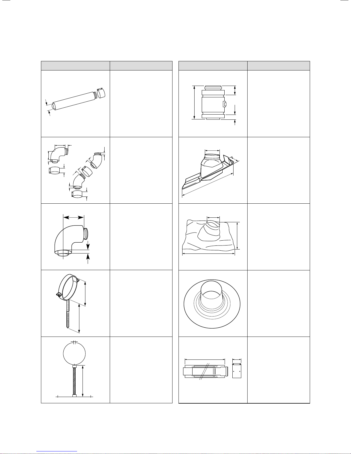
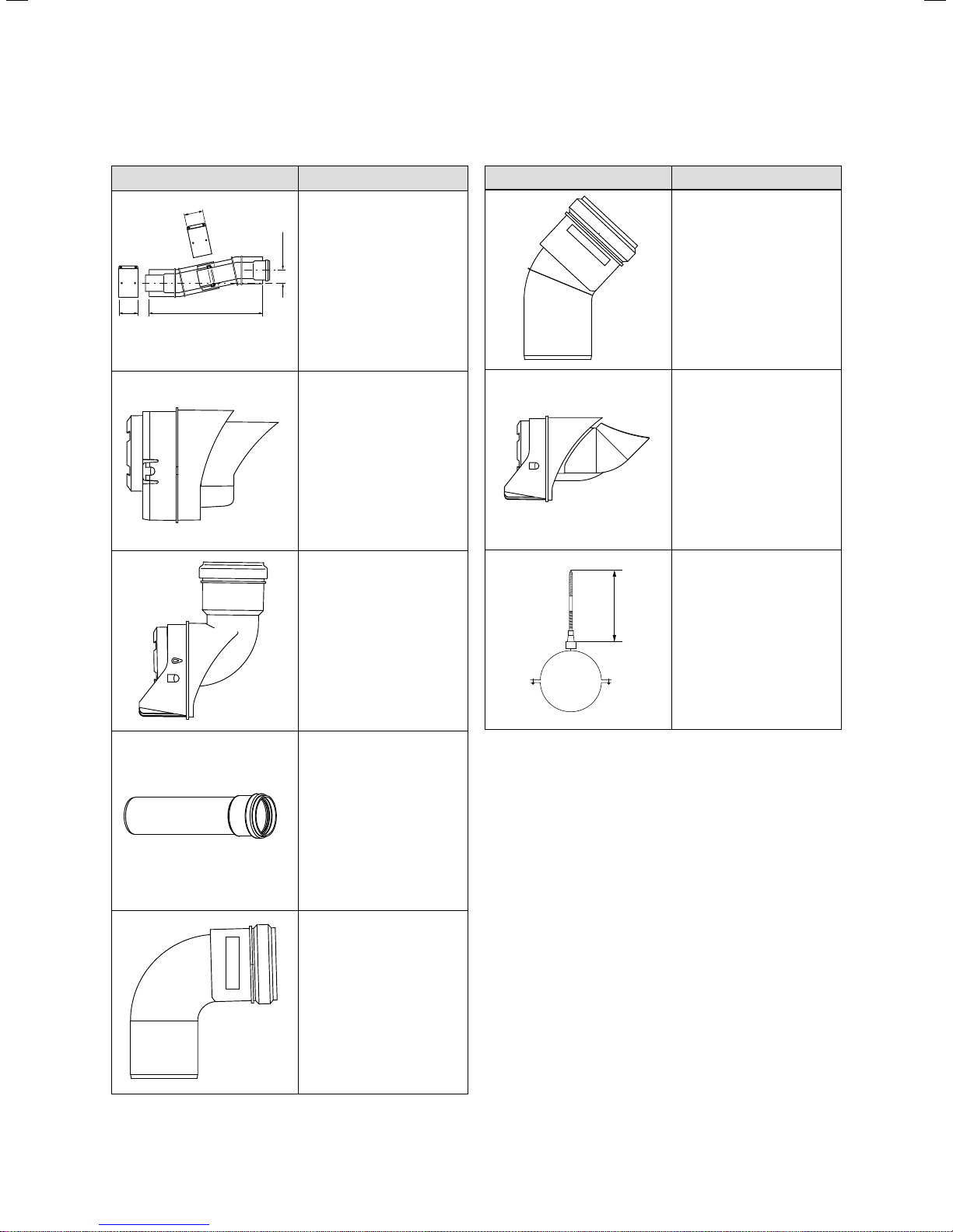
Description of components
Component Description
Extension, dia. 60/100
470 mm: Art. no. 303902
970 mm: Art. no. 303903
1970 mm: Art. no. 303905
60
Elbow, dia. 60/100
87°: Art. no. 303910
45°: Art. no. 303911
27
(set of 2)
Elbow 87°, dia. 60/100
Only as part of:
Art. no. 303933
Art. no. 303936
94
18
94
27
18
27
70
18
70
65
Component Description
Sliding sleeve (PP),
dia. 60/100
Art. no. 303915
37
155
132
498
132
23
Roof flashing plate for
pitched roof
Art. no. 009076 (black)
255
Universal flashing plate,
pitched roof (black)
140
100
250
13
Pipe brackets for flue pipe,
dia. 100 (set of 5)
Art. no. 303821
Adjustable pipe brackets for
flue pipe, dia. 100
(set of 3)
Art. no. 303935
495
440 – 690
495
Flat roof flashing
Art. no. 009056
Telescopic extension (PP),
dia. 60/100
440 mm - 690 mm
Art. no. 303906
70
3.2 Components, dia. 60/100
8 Installation Manual air/flue gas system for ecoTEC 834449_16
3.2 Components, dia. 60/100 (continued)
Page 9
Concentric system (standard), dia. 60/100
3
Component Description
Telescopic offset connector,
dia. 60/100
Art. no. 303919
33 – 56
Black terminal kit for horizontal air/flue pipe
Art. no. 303934
Only for 303933 and 303936
Variable terminal kit – black
Art. no. 303942
Only for 303933 and 303936
Variable terminal kit – white
Art. no. 303946
Only for 303933 and 303936
48
48
290 – 374
Component Description
45° elbow for variable terminal kit – black
Art. no. 303945
45° elbow for variable terminal kit – white
Art. no. 303948
Deflector set, DN 60, PP
black
inc. wall seal
Art. no. 0020060584
Deflector set, DN 60, PP white
Art. no. 0020060585
Pipe bracket for flue pipe,
dia. 60 mm
supplied with the sets
60
Extension for variable terminal kit, dia. 60 mm x 1 m –
black
inc. 1 pipe bracket
Art. no. 303943
Extension pipe for variable terminal kit, dia. 60 mm x 1 m –
white
inc. 1 pipe bracket
Art. no. 303 947
87° elbow for variable terminal kit – black
inc. 1 pipe bracket
Art. no. 303944
87° elbow for variable terminal
kit – white
inc. 1 pipe bracket
Art. no. 303949
3.2 Components, dia. 60/100 (continued)
Installation Manual air/flue gas system for ecoTEC 834449_16 9
3.2 Components, dia. 60/100 (continued)
Page 10
Concentric system (standard), dia. 60/100
3
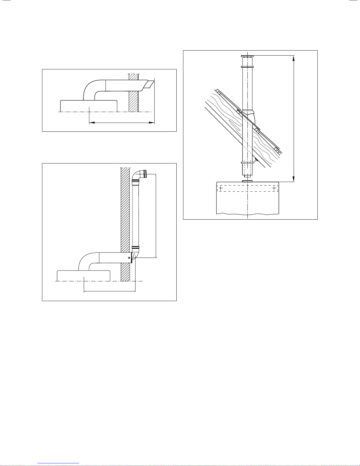
3.2 Maximum permissible pipe lengths
3.1 Horizontal flue systems
Key
A Maximum pipe length
A
B
3.3 Vertical flue systems
Key
A Maximum pipe length
A
A
3.2 Horizontal flue systems with vertical terminal kit
Key
A Concentric pipe length
B Pipe length outdoors
10 Installation Manual air/flue gas system for ecoTEC 834449_16
Page 11
Concentric system (standard), dia. 60/100
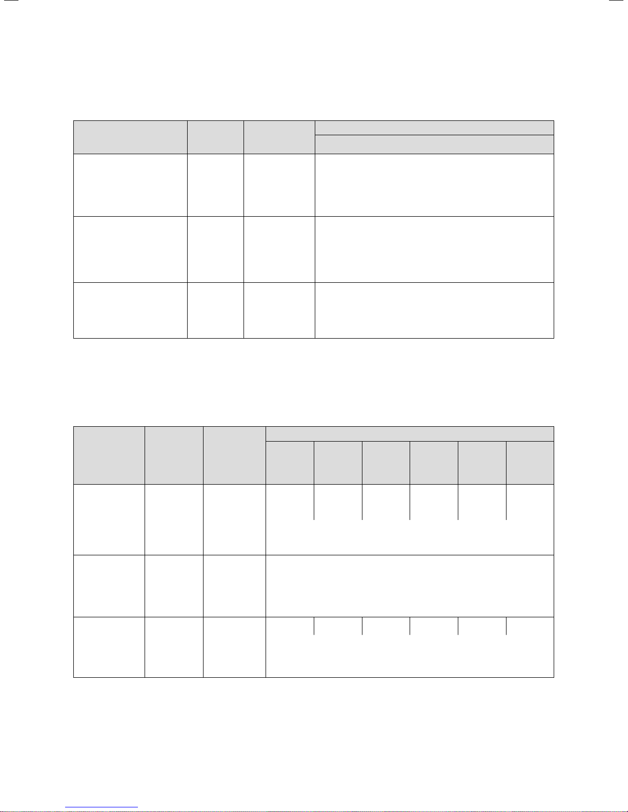
3.2.1 Maximum permitted pipe lengths for
ecoTEC exclusive
3
Accessories Art. no.
Horizontal air/flue pipe 303933
303936
Variable terminal kit 303942
303946
Only in conjunction with
303933 and
303936
Vertical air/flue pipe 0020060570
0020065937
303982
3.3 Maximum permitted pipe lengths for ecoTEC exclusive
Max. permissible
concentric pipe
length
Max. permissible
concentric pipe
length
Max. permissible
concentric pipe
length
3.2.2 Maximum permitted pipe lengths for
ecoTEC
ecoTEC exclusive
832
838
4.0 m
inc.
1 elbow, 87°
The inclusion of additional elbows in the flue system reduces the
maximum pipe length as follows:
- by 1.0 m per 87° elbow,
- by 0.5 m per 45° elbow.
The permissible concentric pipe length stated above is reduced as
follows:
- by 0.5 m with the variable terminal
- by 0.5 m per meter of VTK pipe
- by 0.5 m per 87° elbow
- by 0.5 m for every two 45° elbows
7.0 m
The inclusion of additional elbows in the flue system reduces the
maximum pipe length as follows:
- by 1.0 m per 87° elbow,
- by 0.5 m per 45° elbow.
Accessories Art. no.
Horizontal air/flue
pipe
Variable terminal
kit
Vertical air/flue
pipe
3.4 Maximum permitted pipe lengths for ecoTEC
303933
303936
303942
303946
Only in conjunction with
303933 and
303936
0020060570
0020065937
303982
Max. permissible
concentric pipe
length
Max. permissible
concentric pipe
length
Max. permissible
concentric pipe
length
ecoTEC
plus 612
plus 615
22.0 m
inc.
1 elbow, 87°
The inclusion of additional elbows in the flue system reduces the maximum pipe
The permissible concentric pipe length stated above is reduced as follows:
- by 0.5 m with the variable terminal
- by 0.5 m per meter of VTK pipe
- by 0.5 m per 87° elbow
- by 0.5 m for every two 45° elbows
The pipe length outdoors must not exceed 10 m.
26.0 m 16.0 m 12.0 m 12.0 m 8.0 m 10.0 m
The inclusion of additional elbows in the flue system reduces the maximum pipe
plus 618
plus 824
pro 24
12.0 m
inc.
1 elbow, 87°
plus 624
plus 831
pro 28
pro 828
8.0 m
inc.
1 elbow, 87°
length as follows:
- by 1.0 m per 87° elbow,
- by 0.5 m per 45° elbow.
length as follows:
- by 1.0 m per 87° elbow,
- by 0.5 m per 45° elbow.
plus 630
8.0 m
inc.
1 elbow, 87°
plus 637
plus 837
plus 937
5.5 m
inc.
1 elbow, 87°
plus 415
plus 418
plus 428
plus 438
10.0 m
inc.
1 elbow, 87°
Installation Manual air/flue gas system for ecoTEC 834449_16 11
Page 12
Concentric system (standard), dia. 60/100
3
3.3 Fitting the sliding sleeve
If there is sufficient space available, you can use
a sliding sleeve (art. no. 303915) to connect the
i
3.4 Fitting the sliding sleeve
flue pipe to the boiler flue connection. This consists of a sliding sleeve for the inner flue and an
over centred clip for the outer air duct which
can facilitate easy disconnection of the boiler
from the flue system.
When using the sliding sleeve, you must shorten
the last extension pipe by an additional 95 mm.
1 2
3 4
5
7
> Screw the air-pipe collar to the air pipes using the screws
supplied.
3.4 Fitting the horizontal wall penetration
1
3.5 Flue pipe roof penetration
For horizontal flue systems exiting through
pitched roofs, please order the flue pipe roof
i
a
6
penetration (1) from:
Ubbink (Northants, Tel: 01280 700211)
Danger!
Risk of poisoning due to escaping flue
gas.
Condensate that collects in a particular
place can damage the flue pipe seals.
> Install a horizontal flue pipe with a gradi-
ent of 3° 1° sloping downwards to the
appliance. That equates to a drop of
approx. 50 mm 20 mm per metre of
pipe run.
> Slide the sliding sleeve (1) onto the extension flue pipe
(2) as far as the stop.
> Push the sliding sleeve back until it locates into the
socket (3) of the boiler flue pipe (4).
> Make sure that both ends of the sliding sleeve overlap
the flue pipes by at least 20 mm.
> Fit the air-pipe collar (7) around the air pipes (5 and 6).
> Close the catch on the air-pipe collar.
Danger!
Risk of poisoning due to escaping flue
a
> Drill two holes 3 mm in diameter through the air-pipe
collar and the air pipe. The hole centres should 6 mm
from the edge of the air-pipe collar.
12 Installation Manual air/flue gas system for ecoTEC 834449_16
gas.
Flue gas can escape if the flue pipe is damaged.
> Take care that the flue pipe is not dam-
aged when drilling.
i
The air/flue pipes of the horizontal wall penetra-
tion are not concentric. With the wall penetration fitted horizontally, the flue pipe slopes
downwards at 1.5° towards the inside.
Page 13
Concentric system (standard), dia. 60/100
3
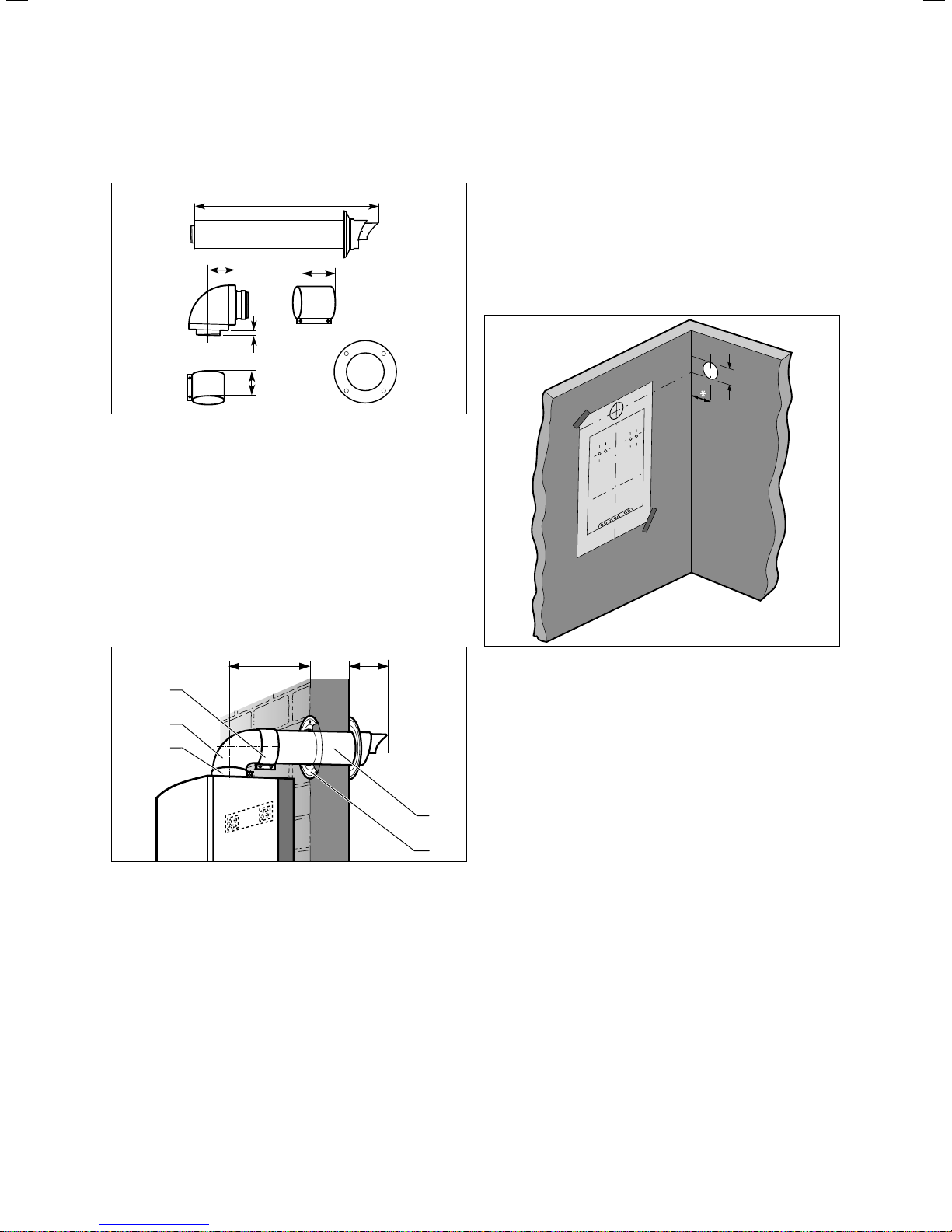
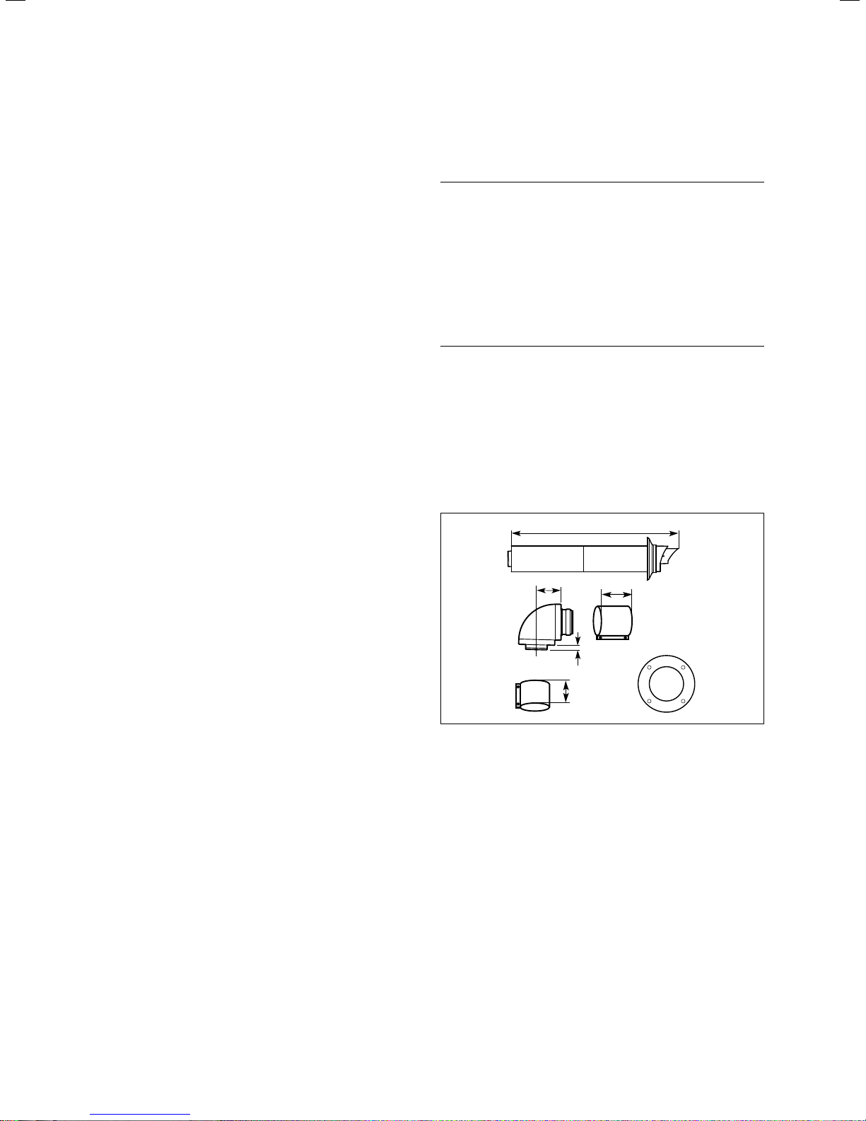
3.4.1 Scope of delivery
65
3.6 Horizontal air/flue pipe
Art. no. 303933
– Horizontal air/flue pipe
– 87° elbow
– 1 x 48-mm air-pipe collar
– 1 x 30-mm air-pipe collar
– Wall rosette, dia. 100
– External wall seal
13
30
754
48
> Using a plumb line or spirit level, check that the centre
line of the mounting template is vertical.
Connection facing upwards, flue exit to rear
If you connect the air/flue pipe directly to the rear of the
boiler, the mounting template shows the position of the wall
penetration for horizontal installation connected to the top
of the boiler.
Connection facing upwards, flue exit to side
3.4.2 Preparing for installation
*
5
4
3
3.7 Fitting the horizontal wall penetration
Key
* = 190 mm for ecoTEC exclusive combination boiler
* = 176 mm for ecoTEC plus open-vented
* = 125 mm for ecoTEC plus boiler & combination boiler
* = 323 mm for ecoTEC plus 937
> Decide on the installation site for the boiler – see boiler
installation instructions.
> Make sure that all clearances required for installation
and servicing can be achieved and that the air/flue gas
system can be installed in accordance with this manual.
> Attach the mounting template supplied with the boiler to
the wall.
87
1
2
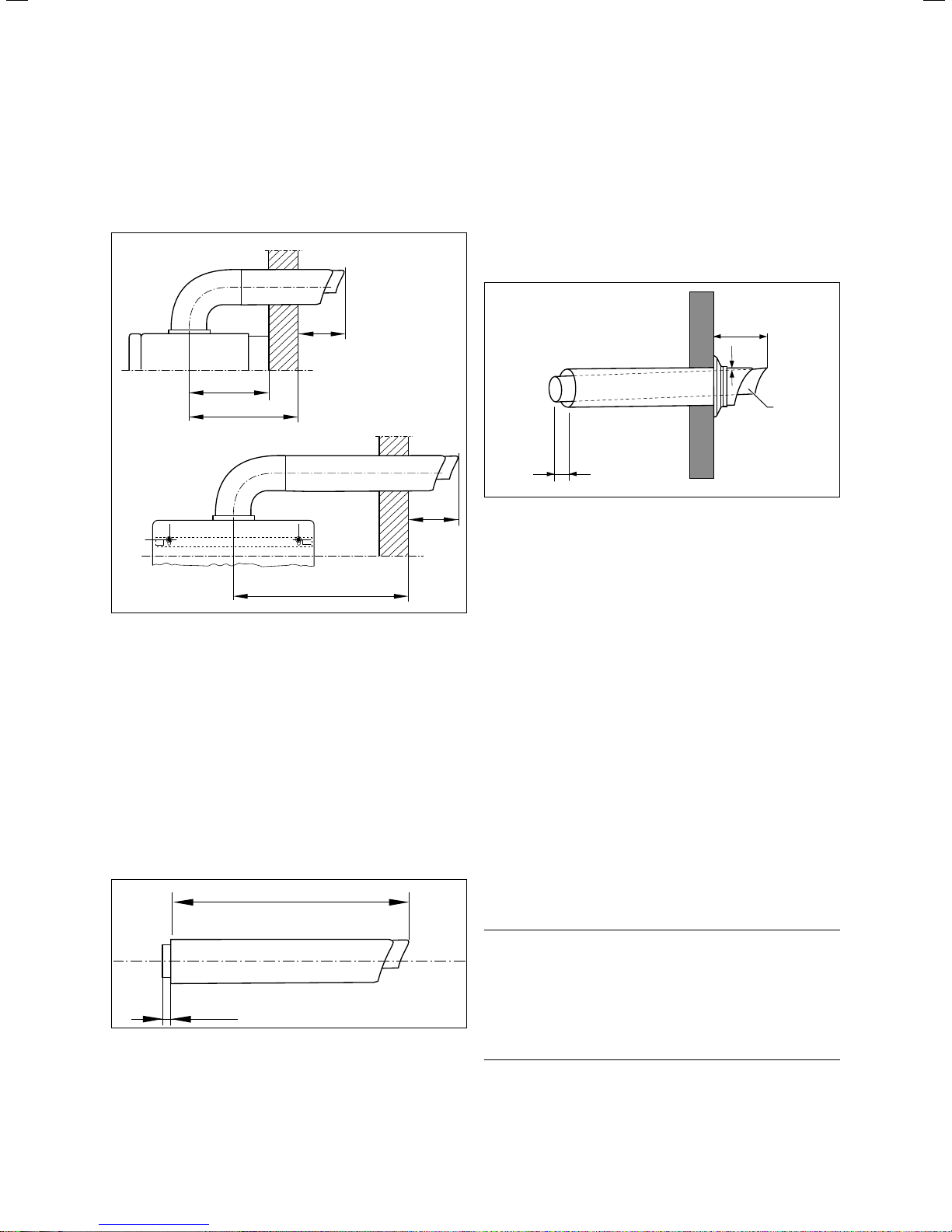
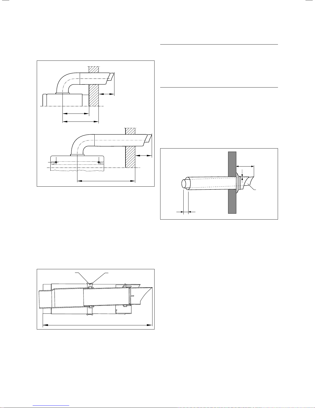
3.8 Distance to external wall
Key
* = 190 mm for ecoTEC exclusive combination boiler
* = 176 mm for ecoTEC plus open-vented
* = 125 mm for ecoTEC plus boiler & combination boiler
* = 323 mm for ecoTEC plus 937
If you wish to install the air/flue pipe to the side of the
boiler, you can determine the position of the wall penetration by carefully transposing the centre line of the wall penetration marked on the mounting template (¬ fig. 3.8).
The position of the wall penetration must allow for installation of the flue pipe with a slight rise of roughly 3°1° (that
equates to 50 mm 20 mm per metre of pipe length).
> Calculate the required rise according to the length of the
flue pipe and then mark the position for the wall penetration.
> If possible drill the hole in the wall with a core drill, diam-
eter 125 mm.
If the desired position for the wall penetration is
accessible from the outside of the building, you
i
can drill the hole with a 107 mm diameter core
drill and insert the external wall seal from the
outside of the building.
Installation Manual air/flue gas system for ecoTEC 834449_16 13
Page 14
Concentric system (standard), dia. 60/100
3
If the desired position for the wall penetration is
accessible from the outside of the building, you
i
can drill the hole with a 107 mm diameter core
drill and insert the external wall seal from the
outside of the building.
1.
87
B
A
2.
87
A
3.9 Distance to external wall
Key
1. Flue exit to rear
2. Flue exit to side
A Distance to external wall
B Distance to internal wall:
= 190 mm for ecoTEC exclusive combination boiler
= 176 mm for ecoTEC plus open-vented
= 125 mm for ecoTEC plus boiler & combination boiler
= 323 mm for ecoTEC plus 937
> Measure the distance from the outside of the wall to the
centre of the boiler flue connection. That corresponds to
the dimension A (¬ fig. 3.9).
A + 22 mm
When cutting the air and flue pipes, remove all
sharp burrs with a file. That will simplify con-
i
> Take care not to scratch the white surface of the air pipe.
If extensions or additional elbows are required for installing
the air/flue pipe, ¬ section 3.12.
3.11 Fitting the horizontal wall penetration
> Push the air/flue pipe (1) together with the external wall
seal through the wall until the external wall seal opens
out again on the outside.
> Pull the air/flue pipe back towards the boiler until the
external wall seal is in contact with the external wall
(¬ fig. 3.6 and ¬ fig. 3.11).
> Make sure that the air/flue pipe (1) is central inside the
hole and that the terminal is correctly positioned with
the inlet grille on the underneath (¬ fig. 3.6 and
¬ fig. 3.11).
> Slide the wall rosette (2) over the air pipe until it is flush
against the wall (¬ fig. 3.7).
> Fix the boiler in position – see boiler installation instruc-
tions.
> Fix the elbow (4) to the boiler by pushing the elbow
spigot into the socket of the boiler flue connection and
securing it with the 30-mm air-pipe collar (3) supplied
(¬ fig. 3.7).
> Pull the air/flue pipe back through the wall so that the
flue pipe is pushed fully home into the socket of the flue
elbow.
> Fit the 48-mm air-pipe collar. When doing so, take care
to align it centrally (5, ¬ fig. 3.7).
necting the pipes together and prevent damage
to the flue pipe seals by sharp edges.
87
3°
1
13
13 mm
3.10 Length of air pipe
> Cut the air and flue pipes to length (¬ fig. 3.10).
All flue pipe sockets must face towards the terminal.
14 Installation Manual air/flue gas system for ecoTEC 834449_16
Danger!
Risk of poisoning due to escaping flue
a
gas.
Flue gas can escape if the flue pipe is damaged.
> Take care that the flue pipe is not dam-
aged when drilling.
> Through the holes in each air-pipe collar, drill a hole
3 mm in diameter in the air pipe.
Page 15
Concentric system (standard), dia. 60/100
3
> Screw the air-pipe collars to the air pipes, the elbow and
the boiler using the screws supplied.
> Slide the wall rosette back against the wall and fix it in
position with a small amount of sealant if necessary.
If installing close to a light source, the outlet can
become dirty due to large numbers of flying
i
insects. Point out to the operator that the outlet
should be regularly cleaned.
3.5 Fitting the telescopic horizontal air/flue
pipe
Danger!
Risk of poisoning due to escaping flue
a
i
3.5.1 Scope of delivery
gas.
Condensate that collects in a particular
place can damage the flue pipe seals.
> Install the horizontal flue pipe with a gra-
dient of 3° 1° sloping downwards to the
appliance. That equates to a drop of
approx. 50 mm 20 mm per metre of
pipe run.
The air/flue pipes of the horizontal wall penetra-
tion are not concentric. With the wall penetration fitted horizontally, the flue pipe slopes
downwards at 1.5° towards the inside.
405 - 610
65
3.12 Telescopic horizontal air/flue pipe
Art. no. 303936, length 0.4 - 0.61 m
– Telescopic horizontal air/flue pipe
– 87° elbow
– 1 x 48-mm air-pipe collar
– 1 x 30-mm air-pipe collar
– Wall rosette, dia. 100
– External wall seal
48
13
30
Installation Manual air/flue gas system for ecoTEC 834449_16 15
Page 16
Concentric system (standard), dia. 60/100
3
3.5.2 Preparations
1.
B
A
2.
3.13 Distance to external wall
87
A
87
Danger!
Risk of poisoning due to escaping flue
a
gas.
Flue gas can escape if the flue pipe is damaged.
> Take care that the flue pipe is not dam-
aged when drilling.
> Secure the air-pipe sections by drilling a hole with a
diameter of 3 mm through the locating hole in the air
pipe and inserting the screws supplied.
> Tape over the gap in the telescopic extension with adhe-
sive tape (2) (¬ fig. 3.14).
All flue pipe sockets must face towards the terminal.
> Take care not to scratch the white surface of the air pipe.
If extensions or additional elbows are required for installing
the air/flue pipe, ¬ section 3.12.
87
3°
1
Key
1. Flue exit to rear
2. Flue exit to side
A Distance to external wall
B Distance to internal wall:
= 190 mm for ecoTEC exclusive combination boiler
= 176 mm for ecoTEC plus open-vented
= 125 mm for ecoTEC plus boiler & combination boiler
= 323 mm for ecoTEC plus 937
> Measure the distance from the outside of the wall to the
centre of the boiler flue connection (¬ fig. 3.13). That
corresponds to the dimension A.
1
A + 22 mm
3.14 Fixing the air pipes
Key
1 Screw
2 Tape
Adjust the length of the air and flue pipes to the dimension
shown in fig. 3.14.
2
13
3.15 Fitting the horizontal wall penetration
> Push the air/flue pipe (1) together with the external wall
seal through the wall until the external wall seal opens
out again on the outside wall.
> Pull the air/flue pipe back towards the boiler until the
external wall seal is in contact with the external wall
(¬ fig. 3.7 and ¬ fig. 3.15).
> Make sure that the air/flue pipe (1) is central inside the
hole and that the terminal is correctly positioned with
the inlet grille on the underneath (¬ fig. 3.7 and
¬ fig. 3.15).
> Slide the wall rosette (2) over the air pipe until it is flush
against the wall (¬ fig. 3.7).
> Install the boiler – see boiler installation instructions.
> Fix the elbow (4) to the boiler by pushing the elbow
spigot into the socket of the boiler flue connection and
securing it with the 30-mm air-pipe collar (3) supplied
(¬ fig. 3.7).
> Pull the air/flue pipe back through the wall so that the
flue pipe is pushed fully home into the socket of the
elbow.
> Fit the 48-mm air-pipe collar (5). When doing so, take
care to align it centrally (¬ fig. 3.7).
16 Installation Manual air/flue gas system for ecoTEC 834449_16
Page 17
Concentric system (standard), dia. 60/100
3
Danger!
Risk of poisoning due to escaping flue
a
> Through the holes in each air-pipe collar, drill a hole
3 mm in diameter in the air pipe.
> Screw the air-pipe collars to the air pipes, the elbow and
the boiler using the screws supplied.
> Slide the wall rosette back against the wall and fix it in
position with a small amount of sealant if necessary.
i
gas.
Flue gas can escape if the flue pipe is damaged.
> Take care that the flue pipe is not dam-
aged when drilling.
If installing close to a light source, the outlet can
become dirty due to large numbers of flying
insects. Point out to the operator that the outlet
should be regularly cleaned.
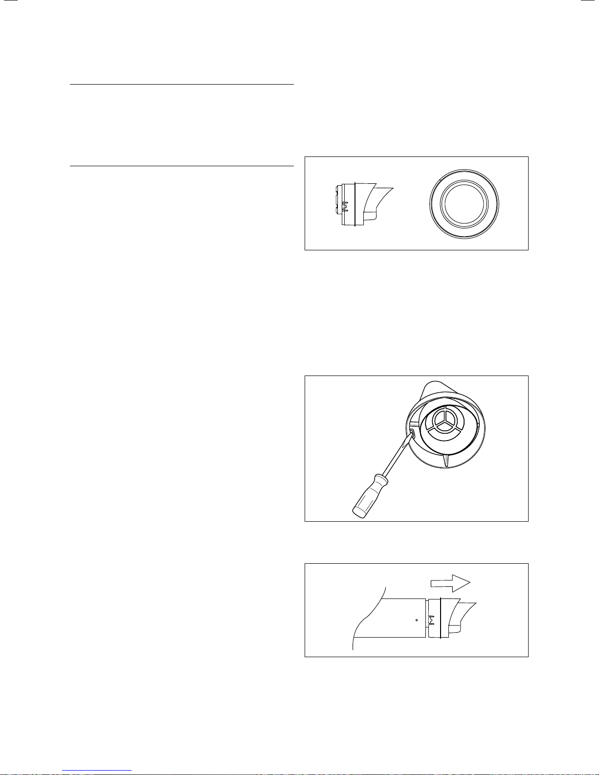
3.6 Fitting the black terminal kit
3.6.1 Scope of delivery
3.16 Black terminal kit,
Art. no. 303934
– Black terminal kit
– External wall seal
3.6.2 Assembling the black terminal kit before
fitting the flue pipe
Installation Manual air/flue gas system for ecoTEC 834449_16 17
3.17 Releasing the catches
> Using an 8-mm screwdriver, press the catches inwards.
3.18 Pulling out the terminal
> Pull the terminal out of the air pipe together with the
flue pipe.
Page 18
Concentric system (standard), dia. 60/100
3
b
Caution.
Risk of damage to the air pipe and appliance.
If rain enters the air pipe, it may cause corrosion of the air pipe and the appliance.
> Make sure that the air-pipe seam is at
the top.
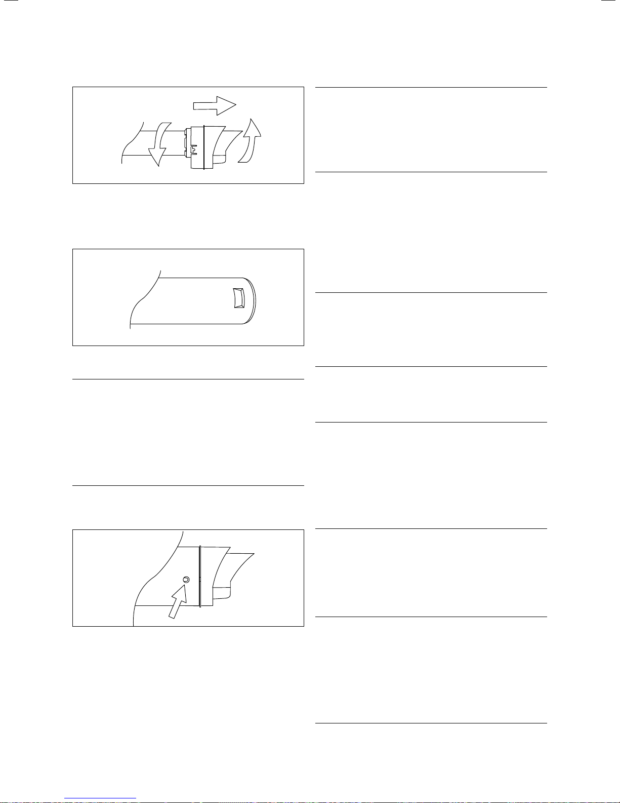
3.19 Releasing the catch
> Release the catch between the terminal and the flue pipe
by twisting the two components in opposite directions.
> Remove the terminal from the flue pipe.
3.20 Recess in flue pipe
Danger!
Risk of poisoning due to escaping flue
a
> Push the new terminal into the flue pipe so that it snaps
into place.
gas.
Flue gas may escape when disconnecting
the pipes.
> Make sure that the lug on the top of the
terminal engages securely in the recess
in the flue pipe.
> Make sure the seal is correctly seated.
> Push the flue pipe together with the terminal back into
the air pipe so that both lugs snap into place.
> Fit the horizontal air/flue pipe according to the instruc-
tions in sections 3.4 and 3.5.
3.6.3 Fitting the black terminal kit after fitting
the flue pipe
Danger!
Risk of poisoning due to escaping flue
a
> Remove the wall seal from the terminal.
> Using an 8-mm screwdriver, press the catches inwards
(¬ fig. 3.17).
a
gas.
> Before starting the conversion work, shut
down the boiler and secure it against
being inadvertently started up again.
Danger!
Risk of poisoning due to escaping flue
gas.
If you twist the flue pipe when pulling the
terminal out of the air pipe, the next flue
pipe may become detached from the
spacer.
> Take care not to twist the flue pipe when
pulling out the terminal.
3.21 Engaging the catch
18 Installation Manual air/flue gas system for ecoTEC 834449_16
> Pull the terminal out of the air pipe together with the
flue pipe (¬ fig. 3.18).
> Release the catch between the terminal and the flue pipe
by twisting the two components in opposite directions
(¬ fig. 3.19).
> Remove the terminal from the flue pipe.
Danger!
Risk of poisoning due to escaping flue
a
gas.
Flue gas may escape when disconnecting
the pipes.
> Make sure that the lug on the top of the
terminal engages securely in the recess
in the flue pipe
> Make sure the seal is correctly seated.
(¬ fig. 3.20).
Page 19

Concentric system (standard), dia. 60/100
3
> Push the new terminal into the flue pipe so that it snaps
into place.
> Push the flue pipe together with the terminal back into
the air pipe.
> Carefully push the flue pipe back into the socket of the
pipe or elbow behind. Make sure the two lugs snap into
place (¬ fig. 3.21).
> Fit the wall seal.
Danger!
Risk of poisoning due to escaping flue
a
3.7 Fitting the variable terminal kit ( VTK)
Minimum clearances for flue terminal
The minimum clearances for the flue terminal as defined in
BS 5440 must be observed unless the boiler manufacturer
is permitted to use smaller clearances that are not considered safety-critical.
Vaillant has reduced the minimum clearances for the flue
terminal and specifies them in the boiler installation
instructions. Those clearances are minimum distances applicable to all types of installation except to installation of the
variable terminal kit (VTK).
If a VTK is connected to a horizontal flue pipe, the terminal
clearances for the air inlet are smaller. The terminal clearances for the "new" flue outlet at the end of the VTK are
unchanged.
gas.
If the flue pipe is not properly fitted, flue
gas can escape.
> Before starting up the boiler, check that
all flue pipe joints are properly seated
and air-tight.
3.7.1 Scope of delivery
3.22 Variable terminal kit
Contents of kit (art. no. 303942, black; art. no. 303946,
white):
– Variable terminal
– 2 x 1 m extension
– 3 x pipe brackets
– 87° elbow with bird-guard grille
3.7.2 Assembling the variable terminal kit before
fitting the flue pipe
Caution.
Risk of damage to the air pipe and appli-
b
ance.
If rain enters the air pipe, it may cause corrosion of the air pipe and the appliance.
> Make sure that the flue outlet of the vari-
able terminal points straight upwards.
For the VTK, the minimum clearance of air inlets A, B and C
from openings such as a window have been reduced to
150 mm. That means that the terminal on the horizontal
flue pipe becomes an air inlet when a VTK is connected and
thus can be installed at a distance of less than 300 mm
from a window opening or ventilation brick.
Installation Manual air/flue gas system for ecoTEC 834449_16 19
Page 20

Concentric system (standard), dia. 60/100
3
55
3.23 Wall clearance
3.26 Releasing the catch
> Release the catch between the terminal and the flue pipe
by twisting the two components in opposite directions.
> Remove the terminal from the flue pipe.
3.24 Releasing the catches
> Using an 8-mm screwdriver, press the catches inwards.
3.25 Pulling out the terminal
> Pull the terminal out of the air pipe together with the
flue pipe.
3.27 Recess in flue pipe
Danger!
Risk of poisoning due to escaping flue
a
> Push the variable terminal into the flue pipe so that it
snaps into place.
3.28 Engaging the catch
gas.
Flue gas may escape when disconnecting
the pipes.
> Make sure that the lug on the top of the
terminal engages securely in the recess
in the flue pipe.
> Make sure the seal is correctly seated.
20 Installation Manual air/flue gas system for ecoTEC 834449_16
Page 21

Concentric system (standard), dia. 60/100
3
Caution.
Risk of damage to the air pipe and appli-
b
> Push the flue pipe together with the variable terminal
back into the air pipe so that both lugs snap into place.
> Fit the horizontal air/flue pipe according to the instruc-
tions in sections 3.4 and 3.5.
ance.
If rain enters the air pipe, it may cause corrosion of the air pipe and the appliance.
> Make sure that the air-pipe seam is at
the top.
Installation is not possible from inside.
i
> Fit the rest of the variable terminal kit according to the
instructions in section 3.7.4.
3.7.3 Fitting the variable terminal kit after fitting
the flue pipe
Danger!
Risk of poisoning due to escaping flue
a
gas.
> Before starting the conversion work, shut
down the boiler and secure it against
being inadvertently started up again.
Danger!
Risk of poisoning due to escaping flue
a
> Push the new variable terminal onto the flue pipe so that
it snaps into place.
> Push the flue pipe together with the terminal back into
the air pipe.
> Carefully push the flue pipe back into the socket of the
pipe or elbow behind.
> Make sure the two lugs snap into place (¬ fig. 3.28).
> Fit the wall seal to the variable terminal.
> Fit the rest of the VTK according to the instructions in
section 3.7.4.
gas.
Flue gas may escape when disconnecting
the pipes.
> Make sure that the lug on the top of the
terminal engages securely in the recess
in the flue pipe.
> Make sure the seal is correctly seated.
> Remove the wall seal from the terminal.
> Using an 8-mm screwdriver, press the catches inwards
(¬ fig. 3.24).
Danger!
Risk of poisoning due to escaping flue
a
> Pull the terminal out of the air pipe together with the
flue pipe (¬ fig. 3.25).
> Release the catch between the terminal and the flue pipe
by twisting the two components in opposite directions
(¬ fig. 3.26).
> Remove the terminal from the flue pipe.
Installation Manual air/flue gas system for ecoTEC 834449_16 21
gas.
If you twist the flue pipe when pulling the
terminal out of the air pipe, the next flue
pipe may become detached from the
spacer.
> Take care not to twist the flue pipe when
pulling out the terminal.
Page 22

Concentric system (standard), dia. 60/100
3
3.7.4 Fitting extensions
Danger!
Risk of poisoning due to escaping flue
a
a
a
gas.
Extensions that are not fixed to a wall may
become disconnected due to sagging or
thermal expansion.
> Fix the extensions to the wall using pipe
brackets.
> Use one bracket for each extension, posi-
tioned right next to the socket.
Danger!
Risk of poisoning due to escaping flue
gas.
Extensions can become disconnected due
to thermal expansion.
> Leave a space of 1 cm in each socket to
allow for expansion.
Danger!
Risk of poisoning due to escaping flue
gas.
If the flue pipe becomes detached, leakage
can occur.
> Before starting up the boiler, check that
all flue pipe joints are properly seated
and air-tight.
The components are assembled simply by being
push-fitted together (not screwed).
i
a
i
i
Danger!
Risk of poisoning due to escaping flue
gas.
If the flue system is not regularly checked,
leaks and corrosion damage can occur.
> As part of the annual service, check the
flue system for the following:
- visible damage such as brittle or
damaged material
- tightly connected pipe joints
- obstruction of the air inlet and flue
outlet by foliage, dead insects, etc.
If installing close to a light source, the outlet can
become dirty due to large numbers of flying
insects. Point out to the operator that the outlet
should be regularly cleaned.
When fitting the variable terminal kit, observe
the maximum permissible pipe lengths
(¬ section 3.2).
3.29 Basic set detailing position of pipe brackets
Danger!
Risk of poisoning due to flue gas.
a
If the 87° elbow with the bird-guard grille is
turned out of position, flue gas may enter
the building through windows or air vents.
> Fix the 87° elbow with bird-guard grille in
position using a separate pipe bracket.
22 Installation Manual air/flue gas system for ecoTEC 834449_16
Page 23

Concentric system (standard), dia. 60/100
3.30 87° elbow with bird-guard grille and pipe bracket
Danger!
Risk of poisoning due to escaping flue
a
gas.
Extensions that are not fixed to a wall may
become disconnected due to sagging or
thermal expansion.
> After each 87° elbow, fix an extra pipe
bracket to the extension.
3
3.31 Basic set with two additional 87° elbows and detailing
position of pipe brackets
3.32 Basic set with two additional 45° elbows and detailing
position of pipe brackets
> Fix the pipes and elbows starting from the variable ter-
minal and using the pipe brackets supplied (¬ figs. 3.29
to 3.33)
.
Installation Manual air/flue gas system for ecoTEC 834449_16 23
Page 24

Concentric system (standard), dia. 60/100
3
3.7.5 Fitting variable terminal kit extensions
around roof overhangs
min. 400 mm min. 100 mm
3.8 Fitting the deflector set
3.8.1 Scope of delivery
3.34 Deflector set
Deflector set, DN 60, PP black
(art. no. 0020060584)
– Black terminal kit
– External wall seal
Deflector set, DN 60, PP white
(art. no. 0020060585)
– White terminal kit
3.33 Fitting extensions around roof overhangs
When routing the variable terminal kit around roof overhangs, extra M8 stud bolts are required for the pipe brackets. The stud bolts are available commercially.
> Fix the bird-guard grille from the 87° elbow in the last
extension.
If you use the 87° elbow, you should insert the
extension seal.
i
> You must fix the last extension with two pipe brackets
spaced at least 400 mm apart.
Additional 45° elbows may be required under
certain circumstances.
i
3.8.2 Fitting the deflector set before fitting the
flue pipe
3.35 Releasing the catches
> Using an 8-mm screwdriver, press the catches inwards.
24 Installation Manual air/flue gas system for ecoTEC 834449_16
Page 25

3.36 Pulling out the terminal
Concentric system (standard), dia. 60/100
3
> Pull the terminal out of the air pipe together with the
flue pipe.
3.37 Releasing the catch
> Release the catch between the terminal and the flue pipe
by twisting the two components in opposite directions.
> Remove the terminal from the flue pipe.
3.38 Recess in flue pipe
Danger!
Risk of poisoning due to escaping flue
a
> Push the new terminal into the flue pipe so that it snaps
into place.
gas.
Flue gas may escape when disconnecting
the pipes.
> Make sure that the lug on the top of the
terminal engages securely in the recess
in the flue pipe.
> Make sure the seal is correctly seated.
3.39 Engaging the catch
Caution.
Risk of damage to the air pipe and appli-
b
> Push the flue pipe together with the deflector back into
the air pipe so that both lugs snap into place.
> Fit the horizontal air/flue pipe according to the instruc-
tions in Sections 3.4 and 3.5.
3.8.3 Fitting the deflector set after fitting the
ance.
If rain enters the air pipe, it may cause corrosion of the air pipe and the appliance.
> Make sure that the air-pipe seam is at
the top.
flue pipe
The deflector's flue pipe terminal must point
straight upwards in the centre position.
i
Minimum clearances for flue terminal
The minimum clearances for the flue terminal as defined in
BS 5440 must be observed unless the boiler manufacturer
is permitted to use smaller clearances that are not considered safety-critical.
Vaillant has reduced the minimum clearances for the flue
terminals and specifies them in the boiler installation
instructions. Those clearances are minimum distances applicable to all types of installation.
For the VTK, the minimum clearance of flue terminals A, B
and C from openings such as a window have been reduced
to 150 mm. That means that the terminal on the horizontal
flue pipe becomes an air inlet when a VTK is connected and
thus can be installed at a distance of less than 300 mm
from a window or ventilation brick.
Installation Manual air/flue gas system for ecoTEC 834449_16 25
Page 26

Concentric system (standard), dia. 60/100
3
3.8.4 Fitting the variable terminal kit after fitting
the flue pipe
Danger!
Risk of poisoning due to escaping flue
a
> Remove the wall seal from the terminal.
gas.
> Before starting the conversion work, shut
down the boiler and secure it against
being inadvertently started up again.
3.42 Releasing the catch
> Release the catch between the terminal and the flue pipe
by twisting the two components in opposite directions.
> Remove the terminal from the flue pipe.
3.40 Releasing the catches
> Using an 8-mm screwdriver, press the catches inwards.
3.41 Pulling out the terminal
Danger!
Risk of poisoning due to escaping flue
a
gas.
If you twist the flue pipe when pulling the
terminal out of the air pipe, the next flue
pipe may become detached from the
spacer.
> Take care not to twist the flue pipe when
pulling out the terminal.
3.43 Recess in flue pipe
Danger!
Risk of poisoning due to escaping flue
a
> Fit the deflector on the flue pipe.
3.44 Engaging the catch
gas.
Flue gas may escape when disconnecting
the pipes.
> Make sure that the lug on the top of the
terminal engages securely in the recess
in the flue pipe.
> Make sure the seal is correctly seated.
> Pull the terminal out of the air pipe together with the
flue pipe.
26 Installation Manual air/flue gas system for ecoTEC 834449_16
Page 27

Concentric system (standard), dia. 60/100
3
Caution.
Risk of damage to the air pipe and appli-
b
> Push the flue pipe together with the terminal back into
the air pipe.
> Carefully push the flue pipe back into the socket of the
pipe or elbow behind.
> Make sure the two lugs snap into place.
> Fit the wall seal on the deflector.
3.45 Flue outlet angle in centre position
ance.
If rain enters the air pipe, it may cause corrosion of the air pipe and the appliance.
> Make sure that the air-pipe seam is at
the top.
45°
3.9 Fitting the vertical roof penetration
You can connect the air/flue pipe directly to the boiler flue
connection on the top of the boiler.
To obtain longer flue pipes, you can add extensions.
Observe the maximum permissible pipe lengths
(¬ section 3.2).
i
Components of the air/flue pipe (¬ section 3.1).
i
3.9.1 Scope of delivery
542
1456
48
901
The flue gas stream is directed upwards at an angle of
approx. 45° when the deflector is set in the centre position.
45° 45°
3.46 Possible sideways adjustment
If necessary, the deflector terminal can be rotated 45° to
the left or right. This adjustment possibility enables additional optimisation of the flue.
Danger!
Risk of poisoning due to escaping flue
a
gas.
The deflector may turn of its own accord if
not properly engaged. Flue gas could then
enter the building through windows or air
vents.
> Turn the deflector to one of the three
possible positions until it perceptibly
snaps into position.
3.47 Vertical roof penetration
Art. no. 0020060570 (black)
– Vertical roof penetration
– 48 mm air-pipe collar
– Fixing hoop
Art. no. 0020065937 (black with rosette)
– Vertical roof penetration
– 48 mm air-pipe collar
– Fixing hoop
– Rosette
3.9.2 Preparations
> Decide on the installation site for the boiler – see boiler
installation instructions.
> Make sure that all clearances required for installation
and servicing can be achieved and that the air/flue gas
system can be installed in accordance with this manual.
> Determine the position for the roof penetration.
Installation Manual air/flue gas system for ecoTEC 834449_16 27
Page 28

Concentric system (standard), dia. 60/100
3
You can shorten the vertical air/flue pipe (art.
no. 0020060570, 0020065937). You should
i
i
3.9.3 Fitting the pitched-roof penetration
shorten the outer "white" pipe (air pipe) first
and then the inner pipe (flue pipe) so that it protrudes 13 mm beyond the air pipe. If the flue is
connected directly to the boiler without elbows,
the roof flashing plate penetration must be
aligned vertically.
If you connect an 87° elbow directly to the
boiler, use the 48-mm air-pipe collar supplied at
that point.
1
542
2
2 0 - 50
3
901
Danger
Risk of poisoning and material damage
a
> Determine the point where the vertical air/flue pipe is to
pass through the roof.
> Insert the roof flashing plate (2).
> Insert the roof penetration (1) through the roof flashing
plate from above and push it down until it is flush.
> Align the roof penetration vertically.
> Fix the roof penetration to the roof with the hoop sup-
plied (3).
> Fit the boiler mounting bracket 6).
> Install the boiler (7) – see boiler installation instructions.
due to escaping flue gas as a result of
roof penetration shearing off.
Snow and ice sliding down pitched roofs
can break off the vertical roof penetration
where it exits the roof.
> In regions where heavy snow falls/exten-
sive ice formation can be expected, sit
the vertical roof penetration close to the
ridge or fit a snow guard mesh above the
roof penetration.
Fitting extensions and elbows (¬ section 3.12).
i
0-5
Ø 100
4
5
6
*
7
8
8
100 - 110
5
5
3.48 Vertical roof penetration for pitched roof
Key
* = 190 mm for ecoTEC exclusive combination boiler
* = 176 mm for ecoTEC plus open-vented
* = 125 mm for ecoTEC plus boiler & combination boiler
* = 323 mm for ecoTEC plus 937
** = 750 mm for ecoTEC exclusive combination boiler
** = 530 mm for ecoTEC plus open-vented (top holes in bracket)
** = 622 mm for ecoTEC plus boiler & combination boiler
** = 622 mm for ecoTEC plus 937
**
> Push the sliding sleeve (8) firmly onto the extension.
> Connect the vertical roof penetration (1) to the extension
(4).
> Connect the sliding sleeve (8) to the boiler flue connec-
tion (5).
The sliding sleeve provides for straightforward
fitting and disconnection of the air/flue pipe to/
i
a
> Drill two holes 3 mm in diameter through the air-pipe
collar and the air pipe. The hole centres should 6 mm
from the edge of the air-pipe collar.
> Screw the air-pipe collar to the extension air pipe and
the boiler flue connection using the screws supplied.
> Make sure that all air-pipe collars are centred and
screwed to the air pipes using the self-tapping screws
supplied.
> Fix every extension with at least one pipe bracket.
from the appliance (¬ section 3.3).
Danger!
Risk of poisoning due to escaping flue
gas.
Flue gas can escape if the flue pipe is damaged.
> Take care that the flue pipe is not dam-
aged when drilling.
28 Installation Manual air/flue gas system for ecoTEC 834449_16
Page 29

Concentric system (standard), dia. 60/100
8
100 - 110
3
3.9.4 Fitting the flat-roof penetration
1
542
AB
901
3
4
5
6
7
Ø 100
2
120
*
3.49 Vertical roof penetration for flat roof
The sliding sleeve provides for straightforward
fitting and disconnection of the air/flue pipe to/
i
a
> Drill two holes 3 mm in diameter through the air-pipe
collar and the air pipe. The hole centres should 6 mm
from the edge of the air-pipe collar.
5
> Screw the air-pipe collar to the extension air pipe and
the boiler flue connection using the screws supplied.
> Make sure that all air-pipe collars are centred and
screwed to the air pipes using the self-tapping screws
supplied.
> Fix every extension with at least one pipe bracket.
from the appliance (¬ section 3.3).
Danger!
Risk of poisoning due to escaping flue
gas.
Flue gas can escape if the flue pipe is damaged.
> Take care that the flue pipe is not dam-
aged when drilling.
Key
A Cold roof
B Hot roof
* = 750 mm for ecoTEC exclusive combination boiler
* = 530 mm for ecoTEC plus open-vented (top holes in bracket)
* = 622 mm for ecoTEC plus boiler & combination boiler
* = 622 mm for ecoTEC plus 937
> Fit the flat-roof flashing (2).
> Press the flat-roof flashing firmly in place and glue it
according to the requirements for flat roofs (CP 144) to
ensure it is water-tight.
> Insert the roof penetration (1) from above through
> the flat-roof flashing until it is flush.
> Align the roof penetration vertically.
> Fix the roof penetration to the roof structure with the
fixing hoop supplied (3).
> Fit the boiler mounting bracket 6).
> Install the boiler (7) – see boiler installation instructions.
Fitting extensions and elbows (¬ section 3.12).
i
> Push the sliding sleeve (8) firmly onto the vertical roof
penetration (1) or onto an extension (4) if necessary.
> Connect the sliding sleeve (8) to the boiler flue connection
(5).
Installation Manual air/flue gas system for ecoTEC 834449_16 29
Page 30

Concentric system (standard), dia. 60/100
3
3.10 Fitting ridge tiles
3.10.1 Scope of delivery
760
48
3.50 Ridge-tile terminal
Ridge-tile terminal, black (art. no. 303982)
– Ridge-tile terminal
– 48 mm air-pipe collar
You can add elbows and extensions to connect the ridge-tile
terminal to the boiler.
3.10.3 Fitting the ridge tile
130
130
min.25
133
R
3.51 Ridge tile dimensions
The ridge tile must be purchased from a roof tile manufacturer:
Recommended manufacturers:
Aspect East Anglia Limited
The Old Mill, East Harling
NORWICH, Norfolk
NR16 2QW
Website: www.aspectroofing.co.uk
Contact: Chris Haythorpe
General Manager - Tile Division
Tel: 01953 717777
Fax: 01953 717164
130
130
min.20
max.125°
1
Components of the air/flue pipe (¬ section 3.1).
i
Observe the maximum permissible pipe lengths
(¬ section 3.2).
i
3.10.2 Preparations
> Decide on the installation site for the boiler – see boiler
installation instructions.
> Make sure that all clearances required for installation
and servicing can be achieved and that the air/flue gas
system can be installed in accordance with this manual.
> Determine the point where the ridge-tile terminal is to
pass through the ridge.
If you connect an 87° elbow directly to the
boiler, use the 48-mm air-pipe collar supplied
i
with the vertical air pipe at that point.
3.52 Fitting the ridge tile
> Fit the ridge tile (1) according to the tile manufacturer's
instructions.
30 Installation Manual air/flue gas system for ecoTEC 834449_16
Page 31

Concentric system (standard), dia. 60/100
3
3.10.4 Fitting the ridge-tile terminal
1
3.53 Fitting the ridge-tile terminal
> Insert the ridge-tile terminal in the ridge tile.
> Align the ridge-tile terminal so that the two fixing tabs
(1) are at right-angles to the line of the ridge. That
ensures that the combustion air can be drawn in
between ridge tile and the air-pipe hood above the ridge
tile.
Fitting extensions and elbows (¬ section 3.12).
i
Danger!
Risk of poisoning due to escaping flue
a
> Through the holes in the air-pipe collars, drill holes 3 mm
in diameter in the air pipe.
> Screw the air-pipe collars to the air pipes, the elbow and
the boiler using the screws supplied.
> Make sure that the air-pipe collars are centred and
screwed to the air pipes using the screws supplied.
> Make sure that every extension is held by at least one
pipe bracket.
gas.
Flue gas can escape if the flue pipe is damaged.
> Take care that the flue pipe is not dam-
aged when drilling.
2
1
3.54 Fixing the ridge-tile terminal
> Bend the two fixing tabs (1) around a roof beam (2).
> Fix the fixing tabs with nails or screws.
> Install the boiler – see boiler installation instructions.
> Connect the ridge-tile terminal to the boiler using exten-
sions and elbows.
Installation Manual air/flue gas system for ecoTEC 834449_16 31
Page 32

Concentric system (standard), dia. 60/100
3
3.11 Fitting concentric connector to a chimney
air/flue pipe
The air/flue gas system is assigned identifica-
tions according to EN 1443 from which it is evi-
i
The chimney air/flue pipe must be designed by the manufacturer and approved for negative-pressure operation.
The chimney air/flue pipe should be rated on its identification plate for operation with condensing boilers and a flue
gas temperature of at least 120 °C.
Requirements regarding fire-resistance must be complied
with.
The listed Vaillant ecoTEC gas-fired wall-hung boilers are
approved in accordance with the European and British
standard "PD CEN /TR 1749: 2005, European Guide to the
Classification of Gas Appliances according to the Type of
Flue for the Use of Shared Flue Systems for Type C43
Appliances":
ecoTEC plus 612, 615, 618, 624, 630, 637
ecoTEC pro 24, pro 28
ecoTEC plus 824, plus 831, plus 837 and plus 937
ecoTEC exclusive 832 and 838
ecoTEC plus, models 415, 418, 428 and 438
i
dent that the system meets the fundamental
requirements of the Building Products Directive.
The air/flue gas system is not approved as part
of the heating boiler.
The length of the air/flue pipe must not exceed
1.4 m and 3 elbows.
That equates to a maximum length of 3.4 m for
the C43 connection.
3.11.1 Components suitable for connection
3.55 Set for connecting the chimney air/flue pipe
– 87° elbow Art. 303910
– Extensions
– 470 mm Art. 303902
– 970 mm Art. 303903
– 1970 mm Art. 303905
– Air-pipe collars Art. 303821
3.11.2 Installation example
Danger!
Risk of poisoning due to escaping flue
a
gas.
Condensate that collects in a particular
place can damage the flue pipe seals.
> Install the horizontal flue pipe with a gra-
dient of 3° 1° sloping downwards to the
appliance. That equates to a drop of
approx. 50 mm 20 mm per metre of
pipe run.
32 Installation Manual air/flue gas system for ecoTEC 834449_16
Danger!
Risk of poisoning due to escaping flue
a
> Lay out the air/flue gas system according to EN 13384.
When doing so, observe the technical specifications (flue
gas temperature and mass flow rate) as set out in the
boiler manual.
gas.
The gas-fired wall-hung boilers are not suitable for use with a flue system that operates under pressure.
> The competent person must always
ensure that the air/flue pipe creates negative pressure in the system (in accordance with the European and British
standard PD CEN /TR 1749: 2005, European Guide to the Classification of Gas
Appliances according to the Type of
Flue).
Page 33

Concentric system (standard), dia. 60/100
3
Danger!
Risk of injury due to damage to struc-
a
The stability and fire-proofing properties of chimney shaft
walls can be altered by the insertion of wall plugs and
screws. Therefore, you should mount the appliance on walls
of which the fire-proofing properties will not be impaired by
screws and wall plugs.
tural integrity.
The air/flue gas system may be installed in
a fireproof casing or space with suitable
access points for annual visual inspection
of the entire flue pipe. It must be provided
with suitable fire-proofing at the points
where the flue pipe passes through walls.
> Take care not to damage fire walls when
installing the system.
3.11.3 Installing the boiler
Danger!
Risk of poisoning due to escaping flue
a
gas.
Extensions that are not fixed to a wall or
ceiling may become disconnected due to
sagging or thermal expansion.
> Ensure that every extension is fixed to
the wall or ceiling by means of a pipe
bracket. The distance between two pipe
brackets must not be greater than the
length of the extension.
1 2 3 4 3 5
B
A
3.56 Installation example
3.57 Installing the boiler
A Flue gas
B Combustion air
Dimensions:
* = 190 mm for ecoMAX
combination boiler
* = 176 mm for ecoTEC plus
open-vented
* = 125 mm for ecoTEC plus
system & combination boiler
* = 323 mm for ecoTEC plus 937
> Install the boiler – see boiler installation instructions.
> Slide the wall rosette (5) onto the air pipe.
> Fit the extension (4) and the elbow (2) between the
boiler flue connection and the flue pipe.
> Fit the 40-mm air-pipe collar (1). Take care to align it
centrally.
> Fit the 70-mm air-pipe collars (3). Take care to align
them centrally.
> If necessary, use extensions and elbows (¬ fig. 3.57).
Installation Manual air/flue gas system for ecoTEC 834449_16 33
Page 34

Concentric system (standard), dia. 60/100
3
Danger!
Risk of poisoning due to escaping flue
a
> Through the holes in the air-pipe collars, drill holes 3 mm
in diameter in the air pipe.
> Screw the air-pipe collars to the air pipes, the elbow and
the boiler using the screws supplied.
gas.
Flue gas can escape if the flue pipe is damaged.
> Take care that the flue pipe is not dam-
aged when drilling.
3.12 Fitting extensions and elbows
3.12.1 Fitting extensions
Danger!
Risk of poisoning due to escaping flue
a
a
gas.
Extensions that are not fixed to a wall or
ceiling may become disconnected due to
sagging or thermal expansion.
> Ensure that every extension is fixed to
the wall or ceiling by means of a pipe
bracket. The distance between two pipe
brackets must not be greater than the
length of the extension.
Danger!
Risk of poisoning due to escaping flue
gas.
Condensate that collects in a particular
place can damage the flue pipe seals.
> Install the horizontal flue pipe with a gra-
dient of 3° 1° sloping downwards to the
appliance. That equates to a drop of
approx. 50 mm 20 mm per metre of
pipe run.
3.58 Example of connection using an additional elbow
a
a
Danger!
Risk of poisoning due to escaping flue
gas.
Mineral oil-based lubricants may damage
the seals. The seals should therefore not be
lubricated.
> Only use water or commercially available
soft soap, if necessary, to assist with
installation.
> Do not fit any damaged seals.
> When fitting the pipes, make absolutely
sure the seals are correctly seated.
> File off sharp burrs and chamfer the
ends of the pipes before assembling
them so that the seals are not damaged,
and dispose of the shavings.
> Do not fit any pipes that are dented or
damaged in any other way.
Danger!
Risk of poisoning due to escaping flue
gas.
Flue pipes can separate if they are not correctly centred.
> Secure the flue pipe with the bracket so
that it is correctly centred relative to the
air pipe.
34 Installation Manual air/flue gas system for ecoTEC 834449_16
Page 35

Concentric system (standard), dia. 60/100
3
Danger!
Risk of poisoning due to escaping flue
a
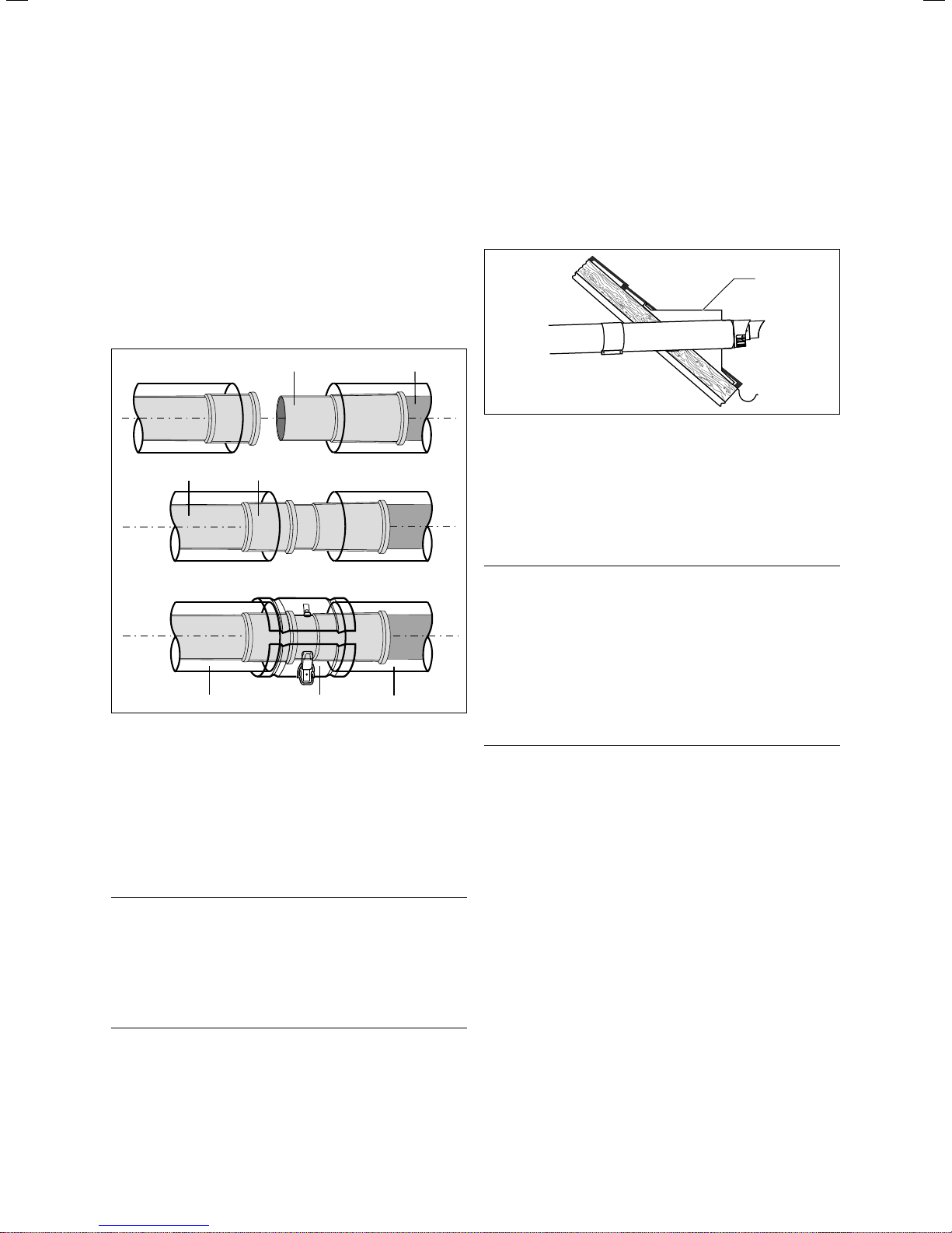
3.59 Detaching the flue pipe
i
gas.
Unsecured joints on the air/flue gas ducting
may become disconnected.
> Secure each air-pipe joint by screwing
the air-pipe collars with the air-pipe ends
or the boiler flue connection.
To cut the air and flue pipes to length sepa-
rately, you can dismantle the pre-assembled
extensions without the use of tools.
3.12.2 Fitting two 87° elbows
Danger!
Risk of poisoning due to escaping flue
a
4
3
2
1
3.61 Arrangement of two 87° elbows – overhead view
1
gas.
Unnecessary strain on the joints can cause
leaks.
> Align the elbows correctly.
1
2
2
*
2
1
+ 40 mm
3.60 Shortening pipes
> First measure the required air pipe length* (A) and then
calculate from that the corresponding flue pipe length
(B):
Length of flue pipe = Length of air pipe + 40 mm
> Cut the pipes with a saw, panel shears, etc.
> After shortening, locate the flue pipe (1) inside the air
pipe (2) again.
* Minimum length of air-pipe extension: 80 mm.
A
1.
B
2.
2
1
13
70
27
3.62 Arrangement of two 87° elbows – front view
2
1
3.63 Arrangement of two 87° elbows – side view
> When using two 87° elbows, refer to figs. 3.61 to 3.63.
* = 3°
*
* = 3°
Installation Manual air/flue gas system for ecoTEC 834449_16 35
Page 36

Concentric system (standard), dia. 60/100
3
90°
max. 5 m
*
1
3.64 Connecting extensions with 87° elbows
The elbow (1) fitted on the top of the boiler must
be turned by 3° so that the second 87° elbow
i
(2) can pass through the wall at right-angles.
max. 5 m
2
* = 3°
a
Danger!
Risk of poisoning due to escaping flue
gas.
Unsecured joints on the air/flue gas ducting
may become disconnected.
> Secure each air-pipe joint by screwing
the air-pipe collars with the air-pipe ends
or the boiler flue connection.
90°
1
3.65 Connecting extensions with 45° elbows
> When using elbows for routing long flue pipes around a
corner, refer to fig. 3.64 and fig. 3.65.
An 87° elbow must be fitted with an angle of 3°
between the wall and the air/flue pipe
i
36 Installation Manual air/flue gas system for ecoTEC 834449_16
¬ fig. 3.64, or else use two 45° elbows
¬ fig. 3.65.
max. 5 m
max. 5 m
Page 37

Concentric system (standard), dia. 60/100
3
3.12.3 Fitting 87° elbows
A
Key
A = Offset
B = Length of air pipe
The elbow supplied with the flue sets 303933
and 303936 does not have the dimensions
i
190
shown here.
Example:
Measure the offset (A), e.g. 400 mm.
95
95
10
B
10
With that figure, refer to the table below to
determine the length of the air pipe (B) = 190 mm
From that, the corresponding flue pipe length can be
calculated as 190 + 40 = 230 mm
3.66 87° elbows (art. no. 303910), fitting
Offset
[in mm]
> 190 to
< 210 mm
> 215 to
< 265 mm
> 270 to
< 290 mm
295 85 485 275 675 465
300 90 490 280 680 470
305 95 495 285 685 475
310 100 500 290 690 480
315 105 505 295 695 485
320 110 510 300 700 490
325 115 515 305 705 495
330 120 520 310 710 500
335 125 525 315 715 505
340 130 530 320 720 510
345 135 535 325 725 515
350 140 540 330 730 520
355 145 545 335 735 525
360 150 550 340 740 530
365 155 555 345 745 535
370 160 560 350 750 540
375 165 565 355 755 545
380 170 570 360 760 550
385 175 575 365 765 555
390 180 580 370 770 560
395 185 585 375 775 565
400 190 590 380 780 570
405 195 595 385 785 575
410 200 600 390 790 580
415 205 605 395 795 585
420 210 610 400 800 590
425 215 615 405
430 220 620 410
435 225 625 415
3.5 Table of offset dimensions
Length of air pipe [in mm] Offset
[in mm]
0 440 230 630 420
445 235 635 425
450 240 640 430
not possible 455 245 645 435
460 250 650 440
465 255 655 445
80 470 260 660 450
475 265 665 455
480 270 670 460
Length of air pipe [in mm] Offset
[in mm]
Length of air pipe [in mm]
Installation Manual air/flue gas system for ecoTEC 834449_16 37
Page 38

Concentric system (standard), dia. 60/100
3
3.12.4 Fitting 45° elbows
A
C
10
B
Key
A = Offset
B = Length of air pipe
C = Height
Example:
Measure the offset (A), e.g. 300 mm.
With that figure, refer to the table below to determine the
length of the air pipe (B) = 284 mm
and the height (C) = 420 mm.
From that, the corresponding flue pipe length is calculated
as 284 + 40 = 324 mm
10
3.67 45° elbows (art. no. 303911), fitting
Offset
[in mm]
90 0 210 325 320 445 525 602 645
95 0 215 330 327 450 530 610 650
100 0 220 335 334 455 535 617 655
> 105 to
< 155 mm
160 86 280 360 369 480 560 652 680
165 93 285 365 376 485 565 659 685
170 100 290 370 383 490 570 666 690
175 107 295 375 390 495 575 673 695
180 115 300 380 397 500 580 680 700
185 122 305 385 404 505 585 687 705
190 129 310 390 412 510 590 694 710
195 136 315 395 419 515 595 701 715
200 143 320 400 426 520 600 709 720
205 150 325 405 433 525 605 716 725
210 157 330 410 440 530 610 723 730
215 164 335 415 447 535 615 730 735
220 171 340 420 454 540 620 737 740
225 178 345 425 461 545 625 744 745
230 185 350 430 468 550 630 751 750
235 192 355 435 475 555 635 758 755
240 199 360 440 482 560 640 765 760
245 206 365 445 489 565 645 772 765
250 214 370 450 496 570 650 779 770
255 221 375 455 503 575 655 786 775
260 228 380 460 511 580 660 793 780
265 235 385 465 519 585 665 800 785
270 242 390 470 525 590 670 808 790
275 249 395 475 532 595 675 815 795
280 256 400 480 539 600 680 822 800
285 263 405 485 546 605
290 270 410 490 553 610
295 277 415 495 560 615
300 284 420 500 567 620
305 291 425 505 574 625
310 298 430 510 581 630
315 306 435 515 588 635
320 313 440 520 595 640
3.6 Table of offset dimensions
Length of
air pipe
[in mm]
not possible 340 341 460 540 624 660
Height [in mm] Offset
[in mm]
345 348 465 545 631 665
350 355 470 550 638 670
355 362 475 555 645 675
Length of
air pipe
[in mm]
Height [in mm] Offset
[in mm]
Length of
air pipe
[in mm]
Height [in mm]
38 Installation Manual air/flue gas system for ecoTEC 834449_16
Page 39

Concentric system (optional), dia. 80/125
4 Concentric system (optional),
dia. 80/125
The air pipes are made of galvanised steel, the flue pipes
out of plastic.
4.1 Product range
4
303200 = Vertical air/flue pipe (black)
303209 = Horizontal air/flue pipe
Optional accessories Art. no.
Boiler flue connection (screw holes, 4 x)
Boiler flue connection bayonet fixing
Extensions, concentric
470 mm - dia. 80/125
Extensions, concentric
970 mm - dia. 80/125
Extensions, concentric
1970 mm - dia. 80/125
Elbows (PP), concentric (set of 2)
45° - dia. 80/125
Elbow (PPs), concentric
87° - dia. 80/125
303926, 0020147469 = Boiler flue connection
303926 X X
0020147469 X X
303202 X X
303203 X X
303205 X X
303211 X X
303210 X X
303 200
303209
Pipe brackets (set of 5), dia. 125
Sliding sleeve (PPs), dia. 80/125
Roof flashing plate for pitched roof
Flat roof flashing
Universal flashing plate, pitched roof
4.1 Product range
Installation Manual air/flue gas system for ecoTEC 834449_16 39
303616 X X
303215 X X
009076 (black) X
009056 X
303980 X
Page 40

Concentric system (optional), dia. 80/125
4
Description of components
Component Description
Boiler flue connection,
dia. 80/125
Art. no. 303926
(with 2 testing points)
Boiler flue connection,
dia. 80/125
Art. no. 0020147469
(with 2 testing points)
Bayonet fixing
Extension (PP), dia. 80/125
470 mm: Art. no. 303202
970 mm: Art. no. 303203
1970 mm: Art. no. 303205
Component Description
Sliding sleeve (PP),
dia. 80/125
Art. no. 303215
164
120
Roof flashing plate for
pitched roof
Art. no. 009076 (black)
Flat roof flashing
Art. no. 009056
80
25
15
15
15
25
125
140
Elbow (PP), 87°, dia. 80/125
Art. no. 303210
25
Elbows (PPs), 45°, dia. 80/125
(set of 2)
Art. no. 303211
Pipe brackets, dia. 125
(set of 5)
Art. no. 303616
132
495
4.2 Components, dia. 80/125 (continued)
Universal flashing plate,
pitched roof (black)
Art. no. 303980
495
4.2 Components, dia. 80/125
40 Installation Manual air/flue gas system for ecoTEC 834449_16
Page 41

4.2 Maximum permissible pipe lengths
A
4.1 Horizontal flue systems
Key
A Maximum length of flue pipe
Concentric system (optional), dia. 80/125
4
4.2 Vertical flue systems
Key
A Maximum length of flue pipe
A
Installation Manual air/flue gas system for ecoTEC 834449_16 41
Page 42

Concentric system (optional), dia. 80/1254
4.2.1 Maximum permitted pipe lengths for
ecoTEC exclusive
Accessories Art. no.
Horizontal air/flue pipe 303209 Max. permissible
Vertical air/flue pipe 303200 Max. permissible
4.3 Maximum permitted pipe lengths for ecoTEC exclusive
concentric pipe
length
concentric pipe
length
4.2.2 Maximum permitted pipe lengths for
ecoTEC
Accessories Art. no.
Horizontal air/flue pipe 303209 Max. permissible
concentric pipe
length
1 elbow, 87°
ecoTEC exclusive
832
838
21.0 m
inc.
1 elbow, 87°
The inclusion of additional elbows in the flue system reduces the maximum
The inclusion of additional elbows in the flue system reduces the maximum
plus 612
plus 615
25.0 m
inc.
plus 618
plus 824
pro 24
39.0 m
inc.
1 elbow, 87°
pipe length as follows:
- by 2.5 m per 87° elbow,
- by 1.0 m per 45° elbow.
22.0 m
pipe length as follows:
- by 2.5 m per 87° elbow,
- by 1.0 m per 45° elbow.
ecoTEC
plus 624
plus 831
pro 28
pro 828
29.0 m
inc.
1 elbow, 87°
plus 630
27.0 m
inc.
1 elbow, 87°
plus 637
plus 837
plus 937
32.0 m
inc.
1 elbow, 87°
plus 415
plus 418
plus 428
plus 438
25.0 m
inc.
1 elbow, 87°
Vertical air/flue pipe 303200 Max. permissible
concentric pipe
length
4.4 Maximum permitted pipe lengths for ecoTEC
The inclusion of additional elbows in the flue system reduces the maximum
27.0 m 41.0 m 31.0 m 29.0 m 34,0 27.0 m
The inclusion of additional elbows in the flue system reduces the maximum
pipe length as follows:
- by 2.5 m per 87° elbow,
- by 1.0 m per 45° elbow.
pipe length as follows:
- by 2.5 m per 87° elbow,
- by 1.0 m per 45° elbow.
42 Installation Manual air/flue gas system for ecoTEC 834449_16
Page 43

Concentric system (optional), dia. 80/125
4
4.3 Replacing the boiler flue connection
Danger!
Risk of poisoning due to escaping flue
a
gas.
Mineral oil-based lubricants may damage
the seals. The seals should therefore not be
lubricated.
> Only use water or commercially available
soft soap, if necessary, to assist with
installation.
4.3.1 Replacing the boiler flue connection on
ecoTEC exclusive and ecoTEC plus open
vented
2
1
4.3 Boiler flue connection (art. no. 303926)
4.3.2 Replacing the boiler flue connection on
ecoTEC plus and ecoTEC pro
3.
1.
2.
4.4 Boiler flue connection (art. no. 0020147469)
The boiler is supplied with an boiler flue connection for the
size 60/100 air/flue gas system.
The boiler flue connection is attached to the boiler by a
bayonet fitting.
> Insert a screwdriver of a suitable size into the slot
between the testing ports.
> Carefully press the screwdriver downwards to release the
boiler flue connection from the catch.
> Turn the boiler flue connection anticlockwise as far as
the stop and then remove it by pulling it upwards.
> Fit the new boiler flue connection (diameter 80/125)
from above so that the lugs locate in the slots in the
socket of the flue header box.
> Turn the boiler flue connection clockwise until it snaps
into position.
The boiler is supplied with an boiler flue connection for the
size 60/100 air/flue pipe system.
> Undo the four screws (2).
> Remove the boiler flue connection (1) by pulling it out
upwards.
> Fit the 80/125 diameter boiler flue connection spigot end
into the socket of the flue header box from above.
> Press the boiler flue connection downwards until the
flange lies flush against the vacuum chamber.
> Re-tighten the 4 screws (2).
Installation Manual air/flue gas system for ecoTEC 834449_16 43
Page 44

Concentric system (optional), dia. 80/125
4
4.4 Fitting the sliding sleeve
If there is sufficient space available, you can use
a sliding sleeve (art. no. 303215) to connect the
i
flue pipe to the boiler flue connection. This consists of a sliding sleeve for the inner flue and an
over centred clip for the outer air duct which
can facilitate easy disconnection of the boiler
from the flue system.
When using the sliding sleeve, you must shorten
the last extension pipe by an additional 85 mm.
1 2
3 4
> Drill two holes 3 mm in diameter through the air-pipe
collar and the air pipe. The hole centres should be 6 mm
from the edge of the air-pipe collar.
> Screw the air-pipe collar to the air pipes using the screws
supplied.
4.5 Fitting the horizontal air/flue pipe
Danger!
Risk of poisoning due to escaping flue
a
i
gas.
Condensate that collects in a particular
place can damage the flue pipe seals.
> Install the horizontal flue pipe with a gra-
dient of 3° 1° sloping downwards to the
appliance. That equates to a drop of
approx. 50 mm 20 mm per metre of
pipe run.
The air/flue pipes of the horizontal wall penetra-
tion are not concentric. With the wall penetration fitted horizontally, the flue pipe slopes
downwards at 1.5° towards the inside.
5
4.5 Fitting the sliding sleeve
> Slide the sliding sleeve (1) onto the extension flue pipe
(2) as far as the stop.
> Push the sliding sleeve back until it locates into the
socket (3) of the boiler flue pipe (4).
> Make sure that both ends of the sliding sleeve overlap
the flue pipes by at least 20 mm.
> Fit the air-pipe collar (7) around the air pipes (5 and 6).
> Close the catch on the air-pipe collar.
Danger!
Risk of poisoning due to escaping flue
a
gas.
Flue gas can escape if the flue pipe is damaged.
> Take care that the flue pipe is not dam-
aged when drilling.
7
6
Observe the maximum permissible pipe lengths
(¬ section 4.2).
i
Components of the air/flue pipe (¬ section 4.1).
i
4.5.1 Scope of delivery
1020
5 1
70
0 7
4.6 Horizontal air/flue pipe
Art. no. 303209
– Horizontal air/flue pipe
– 87° elbow
– 2 x 70 mm air-pipe collar
– 2 x wall rosette, dia. 125
44 Installation Manual air/flue gas system for ecoTEC 834449_16
Page 45

Concentric system (optional), dia. 80/125
4.7 Installation example for horizontal air/flue pipe
4.5.2 Preparations
> Decide on the installation site for the boiler – see boiler
installation instructions.
> Make sure that all clearances required for installation
and servicing can be achieved and that the air/flue gas
system can be installed in accordance with this manual.
> Attach the mounting template supplied with the boiler to
the wall. Using a plumb line or spirit level, check that the
centre line of the mounting template is vertical.
4
Key
* = 190 mm for ecoTEC exclusive combination boiler
* = 176 mm for ecoTEC plus open-vented
* = 125 mm for ecoTEC plus boiler & combination boiler
* = 323 mm for ecoTEC plus 937
> Determine the correct dimensions.
> Measure the distance between the centre line of the two
lower fixing holes in the boiler mounting bracket
(¬ fig. 4.9). That then gives the position of the centre
line of the 87° elbow and the wall penetration.
> The position of the wall penetration can then be deter-
mined by carefully transposing that mark along the wall.
4.5.3 Fitting with side flue exit
> If the air/flue pipe is to exit to the side, you can deter-
mine the position of the air/flue pipe as follows:
4.8 Distance to external wall
4.9 Distance of boiler mounting bracket - wall penetration
Key
* = 190 mm for ecoTEC exclusive combination boiler
* = 176 mm for ecoTEC plus open-vented
* = 125 mm for ecoTEC plus boiler & combination boiler
* = 323 mm for ecoTEC plus 937
The position of the wall penetration must allow for installation of the flue pipe with a rise to the terminal of roughly 3°
1°. That equates to 50 mm 20 mm per metre of flue
pipe length.
> Calculate the required rise according to the length of the
flue pipe and then mark the position for the wall penetration.
Due to the possible length of the air/flue pipe
and the required slope, it may be necessary to
i
> If possible drill the hole in the wall with a core drill, diam-
eter 127 mm.
alter the position of boiler. Before drilling the
holes for the boiler mounting bracket you should
check that both the mounting position of the
boiler and the position of the wall penetration
meet the specified requirements.
Installation Manual air/flue gas system for ecoTEC 834449_16 45
Page 46

Concentric system (optional), dia. 80/125
4
> Cut off the flue pipe at right-angles and remove all sharp
burrs.
> Re-insert the flue pipe into the air pipe and locate it.
A
4.10 Distance to external wall
> Measure the distance from the outside of the wall to the
centre of the boiler flue connection. That corresponds to
the dimension A.
If the measured distance A is greater than 960 mm, an air/
flue pipe extension is required. The number of extensions
usable depends on the boiler.
A
5 mm 5 mm
B
4.11 Air pipe
Key
A = Mark for air pipe
B = Dimension A + 10 mm
> For easier measurement, loosely fit the extensions
together with the terminal.
15 mm
A
4.12 Flue pipe
Key
A = Marking for flue pipe
> Cut the flue pipes to length (¬ fig. 4.12).
When cutting the air and flue pipes, remove all
sharp burrs with a file. That will simplify con-
i
> Take care not to scratch the white surface of the air pipe.
If necessary, use additional extensions and elbows
(¬ section 4.7).
> Install the boiler – see boiler installation instructions.
> Fit the boiler flue connection (¬ section 4.3).
necting the pipes together and prevent damage
to the seals by sharp edges.
25 mm
The individual extensions are joined by push-fit-
ting them together, the spigot of the flue pipe
i
> Fit the flue pipe so that there is a gap of 5 mm between
the individual air pipes. That ensures that the spigots are
inserted in the sockets to the correct depth of 30 mm.
All flue pipe sockets must face towards the terminal.
> Measure from the flue pipe outlet and mark the air pipe
length as follows: dimension A + 60 mm.
> Separate the air and flue pipes.
i
46 Installation Manual air/flue gas system for ecoTEC 834449_16
fitting into a socket with a seal in each case. To
simplify assembly, the seal can be lubricated
with a soap-and-water solution beforehand.
For reasons of correct assembly, you must not
shorten the flue pipes to less than 100 mm. If
necessary, two successive extensions must be
shortened to obtain the desired length.
15
4.13 Fitting the horizontal wall penetration
> Push the assembled air/flue pipe and terminal through
the wall until it protrudes 136 mm from the outside wall.
> Make sure that the terminal is correctly positioned with
the inlet grille on the underneath.
> Slide one of the two wall rosettes over the air pipe until
it lies flush against the interior wall.
> Fit the 87° elbow to the boiler flue connection.
> Connect the wall duct with the 87° elbow.
> Fit the extensions beginning with the wall duct and con-
nect these with the 87° elbow.
136
3°
1
Page 47

Concentric system (optional), dia. 80/125
82 - 90
7
4
Danger!
Risk of poisoning due to escaping flue
a
> Through the holes in the air-pipe collars, drill holes 3 mm
in diameter in the air pipe.
> Screw the air-pipe collars to the air pipes, the elbow and
the boiler using the screws supplied.
4.5.4 Installing the boiler with gap from external
**
*
gas.
Flue gas can escape if the flue pipe is damaged.
> Take care that the flue pipe is not dam-
aged when drilling.
wall
1
6
2
3
4
5
7
> Fit the air-pipe collar (1) on the sliding sleeve.
This section will subsequently serve as a discon-
nection point.
i
> Join all other disconnection points with air-pipe collars.
Danger!
Risk of poisoning due to escaping flue
a
> Through the holes in the air-pipe collars, drill holes 3 mm
in diameter in the air pipe.
> Screw the air-pipe collars to the air pipes, the elbow and
the boiler using the screws supplied.
gas.
Flue gas can escape if the flue pipe is damaged.
> Take care that the flue pipe is not dam-
aged when drilling.
Fitting extensions and elbows (¬ section 4.7).
i
For horizontal flue systems exiting through
pitched roofs, please order the flue pipe roof
i
penetration (7) from:
Ubbink (Northants, Tel: 01280 700211)
4.14 Distance to external wall
Key
* = 750 mm for ecoTEC exclusive combination boiler
* = 530 mm for ecoTEC plus open-vented (from top holes in
bracket)
* = 622 mm for ecoTEC plus boiler & combination boiler
* = 622 mm for ecoTEC plus 937
** = 253 mm for ecoTEC exclusive combination boiler
** = 210 mm for ecoTEC plus open-vented (from top holes in
bracket)
** = 238 mm for ecoTEC plus boiler & combination boiler
** = 238 mm for ecoTEC plus 937
> Fit the boiler mounting bracket (4).
> Install the boiler (5) – see boiler installation instructions.
> Replace the boiler flue connection (3) (¬ section 4.3).
> Fit the 87° elbow to the boiler flue connection.
> Connect the sliding sleeve (7) to the extension (6)
(¬ section 4.4).
> Fit the extensions and connect the sliding sleeve to the
87° elbow.
Installation Manual air/flue gas system for ecoTEC 834449_16 47
Page 48

Concentric system (optional), dia. 80/125
0-5
82 - 90
4
4.6 Fitting the vertical air/flue pipe
Observe the maximum permissible pipe lengths
(¬ section 4.2).
i
4.6.1 Scope of delivery
1430
70
4.15 Vertical roof penetration
4.6.2 Preparing for installation
> Decide on the installation site for the boiler – see boiler
installation instructions.
> Make sure that all clearances required for installation
and servicing can be achieved and that the air/flue gas
system can be installed in accordance with this manual.
> Determine the position for the roof penetration.
You can shorten the vertical air/flue pipe
(art. no. 303200). You should shorten the outer
i
"white" pipe (air pipe) first and then the inner
pipe (flue pipe) so that it protrudes 15 mm
beyond the air pipe. If the flue is connected
directly to the boiler without elbows, the roof
flashing plate penetration must be aligned
vertically.
4.6.3 Fitting the pitched-roof penetration
1
545885
2
20 - 50°
Vertical air/flue pipe, black (art. no. 303200)
– Vertical roof penetration
– Adaptor (air) for dia. 110/125
– 70 mm air-pipe collar
– Fixing hoop
Components of the air/flue pipe (¬ section 4.1).
i
You can connect the air/flue pipe directly to the boiler flue
connection on the top of the boiler.
Extensions can be added to the vertical air/flue pipe and
the terminal.
3
Ø 125
4
5
6
*
7
8
5
4.16 Vertical roof penetration for pitched roof
Key
* = 190 mm for ecoTEC exclusive combination boiler
* = 176 mm for ecoTEC plus open-vented
* = 125 mm for ecoTEC plus boiler & combination boiler
* = 323 mm for ecoTEC plus 937
** = 750 mm for ecoTEC exclusive combination boiler
** = 530 mm for ecoTEC plus open-vented (top holes in bracket)
** = 622 mm for ecoTEC plus boiler & combination boiler
** = 622 mm for ecoTEC plus 937
**
48 Installation Manual air/flue gas system for ecoTEC 834449_16
Page 49

Concentric system (optional), dia. 80/125
7
82 - 90
4
Danger
Risk of poisoning and material damage
a
> Insert the roof flashing plate (2).
> Insert the roof penetration (1) through the roof flashing
plate from above and push it down until it is flush.
> Align the roof penetration vertically.
> Fix the roof penetration to the roof structure with the
hoop supplied (3).
> Fit the boiler mounting bracket 6).
> Install the boiler (7) – see boiler installation instructions.
due to escaping flue gas as a result of
roof penetration shearing off.
Snow and ice sliding down pitched roofs
can break off the vertical roof penetration
where it exits the roof.
> In regions where heavy snow falls/exten-
sive ice formation can be expected, fit
the vertical roof penetration close to the
ridge or fit a snow guard mesh above the
roof penetration.
Fitting extensions and elbows (¬ section 4.7).
i
> Push the sliding sleeve (8) firmly onto the extension.
> Connect the vertical roof penetration (1) to the extension
(4).
> Connect the sliding sleeve (8) to the boiler flue connec-
tion (5).
4.6.4 Fitting the flat-roof penetration
1
545
A
885
3
4
5
6
*
4.17 Vertical roof penetration for flat roof
Key
A Cold roof
B Hot roof
* = 750 mm for ecoTEC exclusive combination boiler
* = 530 mm for ecoTEC plus open-vented (top holes in bracket)
* = 622 mm for ecoTEC plus boiler & combination boiler
* = 622 mm for ecoTEC plus 937
B
Ø 125
2
Ø 120
4
The sliding sleeve provides for straightforward
fitting and disconnection of the air/flue pipe to/
i
a
> At suitable points, drill two holes 3 mm in diameter
through the air-pipe collar of the sliding sleeve.
> Screw the air-pipe collar to the extension air pipe and
the boiler flue connection using the screws supplied.
> Make sure that all air-pipe collars are centred and
screwed to the air pipes using the self-tapping screws
supplied.
> Fix every extension with at least one pipe bracket.
from the appliance (¬ section 4.3).
Danger!
Risk of poisoning due to escaping flue
gas.
Flue gas can escape if the flue pipe is damaged.
> Take care that the flue pipe is not dam-
aged when drilling.
> Fit the flat-roof flashing (2).
> Press the flat-roof flashing firmly in place and glue it
according to the requirements for flat roofs (CP 144) to
ensure it is water-tight.
> Insert the vertical roof penetration (1) through the roof
flashing plate from above and push it down until it is
flush.
> Align the roof penetration vertically.
> Fix the roof penetration to the roof structure with the
hoop supplied (3).
> Fit the boiler mounting bracket (5).
> Install the boiler (6) – see boiler installation instructions.
Fitting extensions and elbows (¬ section 4.7).
i
Installation Manual air/flue gas system for ecoTEC 834449_16 49
Page 50

Concentric system (optional), dia. 80/125
4
> Push the sliding sleeve (7) firmly onto the vertical roof
penetration (1) or onto an extension if necessary.
> Connect the sliding sleeve (7) to the boiler flue connec-
tion (4).
The sliding sleeve provides for straightforward
fitting and disconnection of the air/flue pipe to/
i
a
> Drill two holes 3 mm in diameter through the air-pipe
collar and the air pipe. The hole centres should 6 mm
from the edge of the air-pipe collar.
> Screw the air-pipe collar to the extension air pipe and
the boiler flue connection using the screws supplied.
> Make sure that all air-pipe collars are centred and
screwed to the air pipes using the self-tapping screws
supplied.
> Fix every extension with at least one pipe bracket.
from the appliance (¬ section 4.3).
Danger!
Risk of poisoning due to escaping flue
gas.
Flue gas can escape if the flue pipe is damaged.
> Take care that the flue pipe is not dam-
aged when drilling.
4.7 Fitting extensions and elbows
4.7.1 Fitting extensions
Danger!
Risk of poisoning due to escaping flue
a
a
gas.
Extensions that are not fixed to a wall or
ceiling may become disconnected due to
sagging or thermal expansion.
> Ensure that every extension is fixed to
the wall or ceiling by means of a pipe
bracket. The distance between two pipe
brackets must not be greater than the
length of the extension.
Danger!
Risk of poisoning due to escaping flue
gas.
Condensate that collects in a particular
place can damage the flue pipe seals.
> Install the horizontal flue pipe with a gra-
dient of 3° 1° sloping downwards to the
appliance. That equates to a drop of
approx. 50 mm 20 mm per metre of
pipe run.
a
a
Danger!
Risk of poisoning due to escaping flue
gas.
Mineral oil-based lubricants may damage
the seals. The seals should therefore not be
lubricated.
> Only use water or commercially available
soft soap, if necessary, to assist with
installation.
> Do not fit any damaged seals.
> When fitting the pipes, make absolutely
sure the seals are correctly seated.
> File off sharp burrs and chamfer the
ends of the pipes before assembling
them so that the seals are not damaged,
and dispose of the shavings.
> Do not fit any pipes that are dented or
damaged in any other way.
Danger!
Risk of poisoning due to escaping flue
gas.
> Secure the flue pipe with the bracket so
that it is correctly centred relative to the
air pipe.
50 Installation Manual air/flue gas system for ecoTEC 834449_16
Page 51

Concentric system (optional), dia. 80/125
4
Danger!
Risk of poisoning due to escaping flue
a
4.18 Detaching the flue pipe
i
gas.
Unsecured joints on the air/flue gas ducting
may become disconnected.
> Secure each air-pipe joint by screwing
the air-pipe collars with the air-pipe ends
or the boiler flue connection.
To cut the air and flue pipes to length sepa-
rately, you can dismantle the pre-assembled
extensions without the use of tools.
4.7.2 Fitting two 87° elbows
Danger!
Risk of poisoning due to escaping flue
a
4
3
2
1
4.20 Arrangement of two 87° elbows – overhead view
1
gas.
Unnecessary strain on the joints can cause
leaks.
> Align the elbows correctly.
1
2
2
*
2
1
+ 40 mm
4.19 Shortening pipes
> First measure the required air pipe length* (A) and then
calculate from that the corresponding flue pipe length
(B):
Length of flue pipe = Length of air pipe + 40 mm
> Cut the pipes with a saw, panel shears, etc.
> After shortening, locate the flue pipe (1) inside the air
pipe (2) again.
* Minimum length of air-pipe extension: 80 mm.
A
1.
B
2.
>
2
1
13
70
27
4.21 Arrangement of two 87° elbows – front view
2
1
4.22 Arrangement of two 87° elbows – side view
> When using two 87° elbows, refer to figs. 4.20 to 4.22.
* = 3°
*
* = 3°
Installation Manual air/flue gas system for ecoTEC 834449_16 51
Page 52

Concentric system (optional), dia. 80/125
4
90°
max. 5 m
*
1
4.23 Connecting extensions with 87° elbows
The elbow (1) fitted on the top of the boiler must
be turned by 3° so that the second 87° elbow
i
(2) can pass through the wall at right-angles.
max. 5 m
2
* = 3°
a
Danger!
Risk of poisoning due to escaping flue
gas.
Unsecured joints on the air/flue gas ducting
may become disconnected.
> Secure each air-pipe joint by screwing
the air-pipe collars with the air-pipe ends
or the boiler flue connection.
90°
1
4.24 Connecting extensions with 45° elbows
> When using elbows for routing long flue pipes around a
corner, refer to fig. 4.23 and fig. 4.24.
An 87° elbow must be fitted with an angle of 3°
between the wall and the air/flue pipe
i
52 Installation Manual air/flue gas system for ecoTEC 834449_16
(¬ fig. 4.23), or else use two 45° elbows
(¬ fig. 4.24).
max. 5 m
max. 5 m
Page 53

4.7.3 Fitting 87° elbows
Concentric system (optional), dia. 80/125
4
A
190
Key
A = Offset
B = Length of air pipe
Example:
Measure the offset (A), e.g. 400 mm.
With that figure, refer to the table below to determine the
length of the air pipe (B) = 190 mm
95
10
B
95
10
From that, the corresponding flue pipe length is calculated
as 190 + 40 = 230 mm
4.25 Fitting 87° elbows (art. no. 303210)
Offset [in mm] Length of air pipe
200, 205, 210 0 505 295 730 520
> 210 to
< 310
310 100 535 325 760 550
315 105 540 330 765 555
320 110 545 335 770 560
325 115 550 340 775 565
330 120 555 345 780 570
335 125 560 350 785 575
340 130 565 355 790 580
345 135 570 360 795 585
350 140 575 365 800 590
355 145 580 370 805 595
360 150 585 375 810 600
365 155 590 380 815 605
370 160 595 385 820 610
375 165 600 390 825 615
380 170 605 395 830 620
385 175 610 400 835 625
390 180 615 405 840 630
395 185 620 410 845 635
400 190 625 415 850 640
405 195 630 420 855 645
410 200 635 425 860 650
415 205 640 430 865 655
420 210 645 435 870 660
425 215 650 440 875 665
440 220 655 445 880 670
445 225 660 450 885 675
440 230 665 455 890 680
445 235 670 460 895 685
450 240 675 465 900 690
455 245 680 470 905 695
460 250 685 475 910 700
465 255 690 480 915 705
470 260 695 485 920 710
475 265 700 490 925 715
480 270 705 495 930 720
485 275 710 500 935 725
490 280 715 505 940 730
495 285 720 510
500 290 725 515
4.5 Table of offset dimensions
[in mm]
not possible 520 310 745 535
Offset [in mm] Length of air pipe
[in mm]
510 300 735 525
515 305 740 530
525 315 750 540
530 320 755 545
Offset [in mm] Length of air pipe
[in mm]
Installation Manual air/flue gas system for ecoTEC 834449_16 53
Page 54

Concentric system (optional), dia. 80/125
4
4.7.4 Fitting 45° elbows
A
C
10
B
Key
A = Offset
B = Length of air pipe
C = Height
Example:
Measure the offset (A), e.g. 300 mm.
With that figure, refer to the table below to determine
the length of the air pipe (B) = 284 and the height (C) =
420 mm.
From that, the corresponding flue pipe length is calculated
10
4.26 Fitting 45° elbows (art. no. 303211)
Offset
[in mm]
90 0 210 335 334 455 535 617 655
95 0 215 340 341 460 540 624 660
100 0 220 345 348 465 545 631 665
> 100 to <
170 mm
170 100 290 370 383 490 570 666 690
175 108 295 375 390 495 575 673 695
180 115 300 380 397 500 580 680 700
185 122 305 385 405 505 585 687 705
190 129 310 390 412 510 590 695 710
195 136 315 395 419 515 595 702 715
200 143 320 400 426 520 600 709 720
205 150 325 405 433 525 605 716 725
210 157 330 410 440 530 610 723 730
215 164 335 415 447 535 615 730 735
220 171 340 420 454 540 620 737 740
225 178 345 425 461 545 625 744 745
230 185 350 430 468 550 630 751 750
235 192 355 435 475 555 635 758 755
240 199 360 440 482 560 640 765 760
245 207 365 445 489 565 645 772 765
250 214 370 450 496 570 650 779 770
255 221 375 455 504 575 655 786 775
260 228 380 460 511 580 660 794 780
265 235 385 465 518 585 665 801 785
270 242 390 470 525 590 670 808 790
275 249 395 475 532 595 675 815 795
280 256 400 480 539 600 680 822 800
285 263 405 485 546 605 685 829 805
290 270 410 490 553 610 690 836 810
295 277 415 495 560 615 695 843 815
300 284 420 500 567 620 700 850 820
305 291 425 505 574 625 705 857 825
310 298 430 510 581 630 710 864 830
315 306 435 515 588 635 715 871 835
320 313 440 520 596 640 720 878 840
325 320 445 525 603 645
330 327 450 530 610 650
4.6 Table of offset dimensions
Length of air
pipe [in mm]
not possible 350 355 470 550 638 670
Height
[in mm]
Offset
[in mm]
355 362 475 555 645 675
360 369 480 560 652 680
365 376 485 565 659 685
as 284 + 40 = 324 mm
Length of air
pipe [in mm]
Height
[in mm]
Offset
[in mm]
Length of air
pipe [in mm]
Height
[in mm]
54 Installation Manual air/flue gas system for ecoTEC 834449_16
Page 55

5 Vaillant Service
To ensure regular servicing, it is strongly recommended
that arrangements are made for a Maintenance Agreement.
Please contact Vaillant Service Solutions
(0870 6060 777) for further details.
Vaillant Service
5
Installation Manual air/flue gas system for ecoTEC 834449_16 55
Page 56

Index
Index
B
Bird-guard grille .......................................................................... 23
C
Components
dia. 60/100 ................................................................................ 8
dia. 80/125............................................................................... 40
D
Deflector terminal
Possible adjustment .............................................................. 27
F
Fitting extensions and elbows
dia. 60/100 .............................................................................. 34
dia. 80/125............................................................................... 50
Fitting extensions around roof overhangs ........................... 24
Fitting ridge tiles ......................................................................... 30
Fitting the black terminal kit .................................................... 17
Fitting the deflector set ............................................................ 24
Fitting the disconnection joint .......................................... 12, 44
Fitting the variable terminal kit (VTK) ................................... 19
Flat-roof penetration
dia. 60/100 .............................................................................. 29
dia. 80/125............................................................................... 49
P
Pipe lengths
dia. 60/100 ............................................................................... 10
dia. 80/125................................................................................ 41
Pitched-roof penetration
dia. 60/100 .............................................................................. 28
dia. 80/125............................................................................... 48
Product range
dia. 60/100 ................................................................................ 6
dia. 80/125............................................................................... 39
R
Replacing boiler flue connection ............................................ 43
T
Telescopic horizontal air/flue pipe .......................................... 15
V
Vertical roof penetration .......................................................... 27
VTK ........................................................................................... 19, 25
H
Horizontal wall penetration ....................................................... 12
M
Minimum clearances for flue terminal............................. 19, 25
Mounting template ...................................................................... 13
56 Installation Manual air/flue gas system for ecoTEC 834449_16
Page 57

Page 58

Page 59

Page 60

834449
Supplier
Manufacturer
834449_16 GBIE 052012 – Subject to change
 Loading...