

Vaillant 824/2 E, 828/2E, 620/2 E, 624/2 E, 837E Instructions For Installation Manual
...
Supplied By www.heating spares.co Tel. 0161 620 6677
For the installer
824/2 E
828/2 E
837 E
615/2 E
620/2 E
624/2 E
628/2 E
637 E
GB
Instructions for Installation and Servicing
turboMAX plus and thermoCOMPACT
Wall hung room sealed fan assisted
combination and system boilers

Supplied By www.heating spares.co Tel. 0161 620 6677
Table of Contents
Instructions for Installation and Servicing turboMAX plus and thermoCOMPACT R12
Page
1 List of Contents . . . . . . . . . . . . . . . . . . . . . . . . . 4
1.1 Contents included with boiler (turboMAX plus) 4
1.2 Contents included with boiler (thermoCOMPACT) 4
2 Introduction . . . . . . . . . . . . . . . . . . . . . . . . . . . . 5
2.1
General Information . . . . . . . . . . . . . . . . 5
2.2 General notes . . . . . . . . . . . . . . . . . . . . . . . . . . . 5
2.3 EC designation . . . . . . . . . . . . . . . . . . . . . . . . . . 5
3 Boiler Specification . . . . . . . . . . . . . . . . . . . . . . 6
3.1
Technical data . . . . . . . . . . . . . . . . . . . . 6
3.2Boiler connections (turboMAX plus) . . . . . . . . 8
3.3Boiler connections (thermoCOMPACT) . . . . . . 8
3.4Functional diagram (turboMAX plus) . . . . . . . . 8
3.5Functional diagram (thermoCOMPACT) . . . . . . 9
4 General Requirements . . . . . . . . . . . . . . . . . . . . 10
4.1Related documents . . . . . . . . . . . . . . . . . . . . . . 10
4.2Boiler location . . . . . . . . . . . . . . . . . . . . . . . . . . 10
4.3 Gas supply . . . . . . . . . . . . . . . . . . . . . . . . . . . . . 10
4.4 Flue system . . . . . . . . . . . . . . . . . . . . . . . . . . . . . 10
4.4.1Top outlet flue system . . . . . . . . . . . . . . . . . . . . 11
4.4.2Rear outlet flue system . . . . . . . . . . . . . . . . . . . 11
4.4.3 Extended top outlet flue system . . . . . . . . . . . 11
4.4.4 Flue termination . . . . . . . . . . . . . . . . . . . . . . . . 12
4.5 Air supply . . . . . . . . . . . . . . . . . . . . . . . . . . . . . . 12
4.6Cupboard or compartment ventilation . . . . . . 12
4.7 Electrical supply . . . . . . . . . . . . . . . . . . . . . . . . . 12
4.8 Guide to system requirements . . . . . . . . . . . . . 13
4.8.1 Water circulation system . . . . . . . . . . . . . . . . . . 13
4.8.2 Filling and make up . . . . . . . . . . . . . . . . . . . . . . 13
4.8.3 Pressure relief valve . . . . . . . . . . . . . . . . . . . . . 13
4.8.4 Pressure gauge . . . . . . . . . . . . . . . . . . . . . . . . . 13
4.8.5 Expansion vessel . . . . . . . . . . . . . . . . . . . . . . . . 13
4.8.6 Circulating pump . . . . . . . . . . . . . . . . . . . . . . . . 14
4.8.7 System by-pass . . . . . . . . . . . . . . . . . . . . . . . . . 14
4.8.8 Venting . . . . . . . . . . . . . . . . . . . . . . . . . . . . . . . . 14
5 Boiler Installation Sequence . . . . . . . . . . . . . . . 15
5.1 General . . . . . . . . . . . . . . . . . . . . . . . . . . . . . . . . 15
5.2 Using boiler template . . . . . . . . . . . . . . . . . . . . 16
5.3 Fitting the boiler hanging bracket . . . . . . . . . . 16
5.4 Install the flue system . . . . . . . . . . . . . . . . . . . . 17
5.5 Fitting the boiler . . . . . . . . . . . . . . . . . . . . . . . . 17
5.6Removing boiler casing . . . . . . . . . . . . . . . . . . . 17
5.7 Gas supply (turboMAX plus) . . . . . . . . . . . . . . . 17
5.8Cold water mains inlet and hot water outlet
(turboMAX plus) . . . . . . . . . . . . . . . . . . . . . . . . . 18
5.9Central heating flow and return pipework
(turboMAX plus) . . . . . . . . . . . . . . . . . . . . . . . . . 18
5.10 Gas supply (thermoCOMPACT) . . . . . . . . . . . . . 19
5.11 Central heating flow and return pipework
(thermoCOMPACT) . . . . . . . . . . . . . . . . . . . . . . 19
5.12 Connection to a Vantage unvented cylinder .
(thermoCOMPACT) . . . . . . . . . . . . . . . . . . . . . . 20
Page
5.13 Connect the flue system to the boiler . . . . . . . 20
5.14 Electrical installation . . . . . . . . . . . . . . . . . . . . . 20
5.15 Connection to the main supply . . . . . . . . . . . . 20
5.16 Electronic board layout . . . . . . . . . . . . . . . . . . . 21
5.17 Controls (turboMAX plus boiler) . . . . . . . . . . . . 22
5.18 Controls (thermoCOMPACT boiler) . . . . . . . . . 23
5.19 Thermostatic radiator valves . . . . . . . . . . . . . . 24
5.20 Frost protection . . . . . . . . . . . . . . . . . . . . . . . . . 24
5.21 Circulating pump . . . . . . . . . . . . . . . . . . . . . . . . 24
5.22 Anti-cycling ‘economiser’ control . . . . . . . . . . . 24
6 Commissioning Part I . . . . . . . . . . . . . . . . . . . . 25
6.1 Preliminary electrical checks . . . . . . . . . . . . . . 25
6.2 Gas supply . . . . . . . . . . . . . . . . . . . . . . . . . . . . . 25
6.3 Cold water supply (turboMAX plus only) . . . . . 25
6.4 Filling the heating system (turboMAX plus) . . 25
6.5 Filling the heating system (thermoCOMPACT) 26
6.6 Initial system flush ("cold“) . . . . . . . . . . . . . . . . 26
7 Gas supply adjustments (Commissioning Part II) 26
7. 1 Gas inlet working pressure . . . . . . . . . . . . . . . . 26
7. 2 Main burner pressure . . . . . . . . . . . . . . . . . . . . 27
7. 3Adjusting the central heating output
(range rating) . . . . . . . . . . . . . . . . . . . . . . . . . . . 27
7. 4Adjusting to the maximum heat load
(nominal load) . . . . . . . . . . . . . . . . . . . . . . . . . . 29
7. 5Adjusting the ignition rate . . . . . . . . . . . . . . . . 29
7. 6 Checking and adjusting to the operating point
(turboMAX plus 837E and
thermoCOMPACT 637E only) . . . . . . . . . . . . . . 30
7.7Setting or adjusting the mid-setting point . . . 31
7. 8 Fit combustion chamber cover . . . . . . . . . . . . . 33
7. 9 Fit boiler casing . . . . . . . . . . . . . . . . . . . . . . . . . 33
8 Functional checks (Commissioning Part III) 33
8.1 Functional checks . . . . . . . . . . . . . . . . . . . . . . . 33
8.2 Functional check of operation
(turboMAX plus only) . . . . . . . . . . . . . . . . . . . . . 33
8.3 Functional check of operation
(thermoCOMPACT only) . . . . . . . . . . . . . . . . . . 34
8.4 Adjusting pump speed . . . . . . . . . . . . . . . . . . . . 34
8.5 Handing over to the user . . . . . . . . . . . . . . . . . 35
9 Servicing . . . . . . . . . . . . . . . . . . . . . . . . . . . . . . 35
9.1 Initial inspection . . . . . . . . . . . . . . . . . . . . . . . . . 35
9.2 Cleaning the burner and primary heat
exchanger . . . . . . . . . . . . . . . . . . . . . . . . . . . . . . 35

Supplied By www.heating spares.co Tel. 0161 620 6677
Table of Contents
Instructions for Installation and Servicing turboMAX plus and thermoCOMPACT R1 3
Page
10 Fault Finding . . . . . . . . . . . . . . . . . . . . . . . . . . . 37
10.1 Introduction . . . . . . . . . . . . . . . . . . . . . . . . . . . . 37
10.2 Indicator lights (turboMAX plus only) . . . . . . . 37
10.3 Indicator lights (thermoCOMPACT only) . . . . . 37
10.4 Logical fault finding procedure . . . . . . . . . . . . 36
10.5 Status Modes . . . . . . . . . . . . . . . . . . . . . . . . . . . 38
10.6 Diagnostic Mode . . . . . . . . . . . . . . . . . . . . . . . . . 39
10.7 Fault codes . . . . . . . . . . . . . . . . . . . . . . . . . . . . . 40
10.8 Fault memory . . . . . . . . . . . . . . . . . . . . . . . . . . . 40
10.9 Fault finding charts . . . . . . . . . . . . . . . . . . . . . . 41
11 Diagrams . . . . . . . . . . . . . . . . . . . . . . . . . . . . . . 48
11.1
Functional flow diagrams . . . . . . . . . . . . . 48
12.2 Wiring diagrams . . . . . . . . . . . . . . . . . . . . . . . . . 50
Supplied By www.heating spares.co Tel. 0161 620 6677
1 List of contents
Instructions for Installation and Servicing turboMAX plus and thermoCOMPACT R14
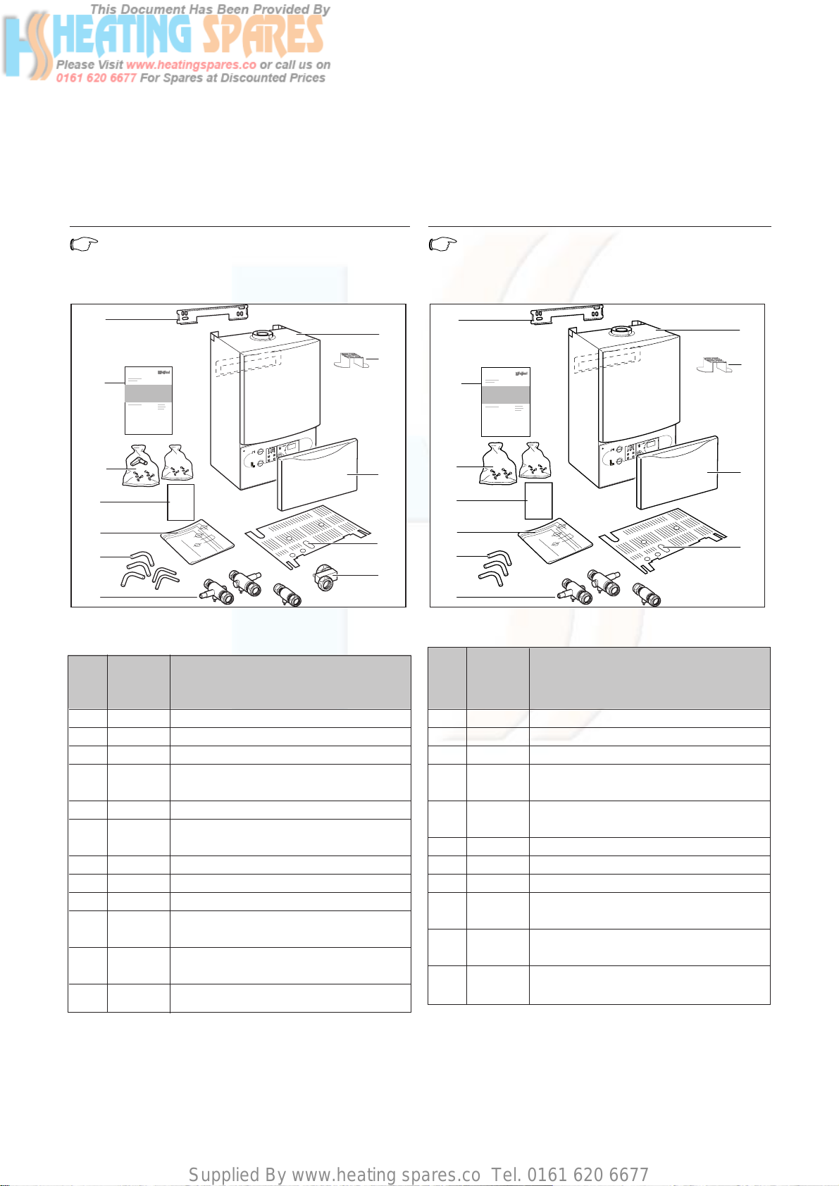
1.2 Contents included with boiler (thermoCOMPACT)
Ensure that all contents are included before
commencing installation.
Note!
DO NOT remove the boiler from the polystrene
base at this stage.
Fig. 1.2: Items supplied with unit (thermoCOMPACT)
9
8
7
1
6
5
2
10
11
VRC-VC
C
o
0
I
C
o
3
4
1 List of contents
1.1 Contents included with boiler (turboMAX plus)
Ensure that all contents are included before
commencing installation.
Note!
DO NOT remove the boiler from the polystrene
base at this stage.
Fig. 1.1: Items supplied with unit (turboMAX plus)
4
10
9
8
1
2
7
6
11
12
VRC-VC
C
o
0
I
C
o
3
5
Item Quantity Description
11 Boiler
21 Flue restriction ring
31 Controls cover door
41 Lower cover plate (packed in bottom
packaging)
51 Cold water inlet valve
63 Flow and return service value, gas service
valve
75 Copper tails for gas and water pipework
81 Template
92 Guarantee Card and Benchmark log book
10 1 Installation and connection accessories and
PRV packages incl. DHW outlet union nut
11 3 Installation and Servicing, Users and Flue
Installation Instructions
12 1 Hanging bracket
Item Quantity Description
11 Boiler
21 Flue restriction ring
31 Controls cover door
41 Lower cover plate (packed in bottom
packaging)
53 Flow and return service value, gas service
valve
63 Copper tails for gas and water pipework
71 Template
82 Guarantee Card and Benchmark log book
91 Installation and connection accessories and
PRV packages
10 3 Installation and Servicing, Users and Flue
Installation Instructions
11 1 Hanging bracket

Supplied By www.heating spares.co Tel. 0161 620 6677
Introduction 2
Instructions for Installation and Servicing turboMAX plus and thermoCOMPACT R1 5
2 Introduction
2.1 General Information
Note!
This boiler must be installed and serviced by a
competent person in accordance with the Gas
Safety (Installation and Use) Regulations 1998.
In the UK "CORGI“ registered installers
undertake the work to a safe and satisfactory
standard.
turboMAX plus boiler
The turboMAX plus is a fully automatic, wall mounted,
room sealed combination boiler for central heating and
domestic hot water. Domestic hot water is supplied
directly from the boiler, without requiring a copper
cylinder, cold water tank, feed and expansion tank and
associated pipework. Domestic hot water has priority
over central heating.
The turboMAX plus range consists of models with
outputs for domestic hot water of 24 kW , 28 kW and 37
kW. All turboMAX plus boilers are available in Natural
Gas. The 24 and 28 kW versions are also available in
LPG.
turboMAX plus combination boilers incorporate a
warmstart facility that keeps the domestic hot water
heat exchanger hot, providing an instantaneous delivery
of domestic hot water.
The temperature in the domestic hot water heat
exchanger is limited by the boiler control system and it
is not necessary to install a scale reducer on the cold
mains to the boiler.
However, in exceptionally hard water areas to prevent
scale formation in the property hot water system
pipework, a scale reducer may be fitted.
The heating system can be filled using the built-in filling
loop contained within the boiler.
thermoCOMPACT boiler
The thermoCOMPACT is a fully automatic, wall mounted,
room sealed system boiler for central heating and
domestic hot water (where a separate indirect hot water
storage cylinder is also incorporated in the system).
The thermoCOMPACT range consists of models with
outputs of 15, 20, 24, 28 kW and 37 kW.
All thermoCOMPACT boilers are available in Natural Gas.
The 20 and 28 kW versions are also available in LPG.
2.2 General Notes
The boilers have been designed for use with a sealed
central heating system, and come fully tested and
assembled with a built in circulating pump, expansion
vessel and diverter valve (turboMAX plus only). The
boilers are not suitable for use on open vented systems.
The boilers are easily sited on any internal wall and can
be installed with either a horizontal or vertical RSF
(room sealed fan assisted) flue. Two types of flue
systems are available, the standard concentric flue
system (100 mm outside diameter) and a larger
diameter concentric flue system (125 mm outside
diameter) which allows longer flue lengths to be
achieved. Flue extensions and additional bends and
elbows are available for both flue systems to increase
the siting flexibility.
There is also a 100 mm diameter concentric flue
accessory which connects to the alternative rear flue
outlet on the boiler for direct through the wall
installations. The boilers are not suitable for external
installation. If desired, an inhibitor may be used in the
system. Guidance on the use of inhibitors is contained in
these instructions.
All boilers have a built in diagnostic system which
indicates the operational status of the boiler.
This feature provides key information to aid
commissioning and fault finding.
The data badge is fitted on the rear of the control panel.
See text of General Requirements for installation
requirements or notes.
Vaillant Ltd. support the Benchmark initiative.
Within the information pack, you will find a Benchmark
Log Book. It is very important that this is completed
correctly at the time of installation, commissioning and
handover to the user.
2.3 EC designation
turboMAX plus (824/828/837) and thermoCOMPACT
boilers (615/620/624/628/637) carry the "CE" Mark. This
demonstrates that the boilers fulfil the essential
requirements of the Gas Appliance
Directive(90/396/EEC) and the Gas Appliance (Safety)
Regulations 1992.
The "CE" Mark also demonstrates that the boilers
comply with the requirements of the Electromagnetic
Compatibility Directive (89/336/EEC), the Low Voltage
Directive (72/23/EEC), the Boiler Efficiency Directive
(92/42/EEC) and the Boiler (Efficiency) Regulations
1993.

Supplied By www.heating spares.co Tel. 0161 620 6677
3 Boiler Specification
Instructions for Installation and Servicing turboMAX plus and thermoCOMPACT R16
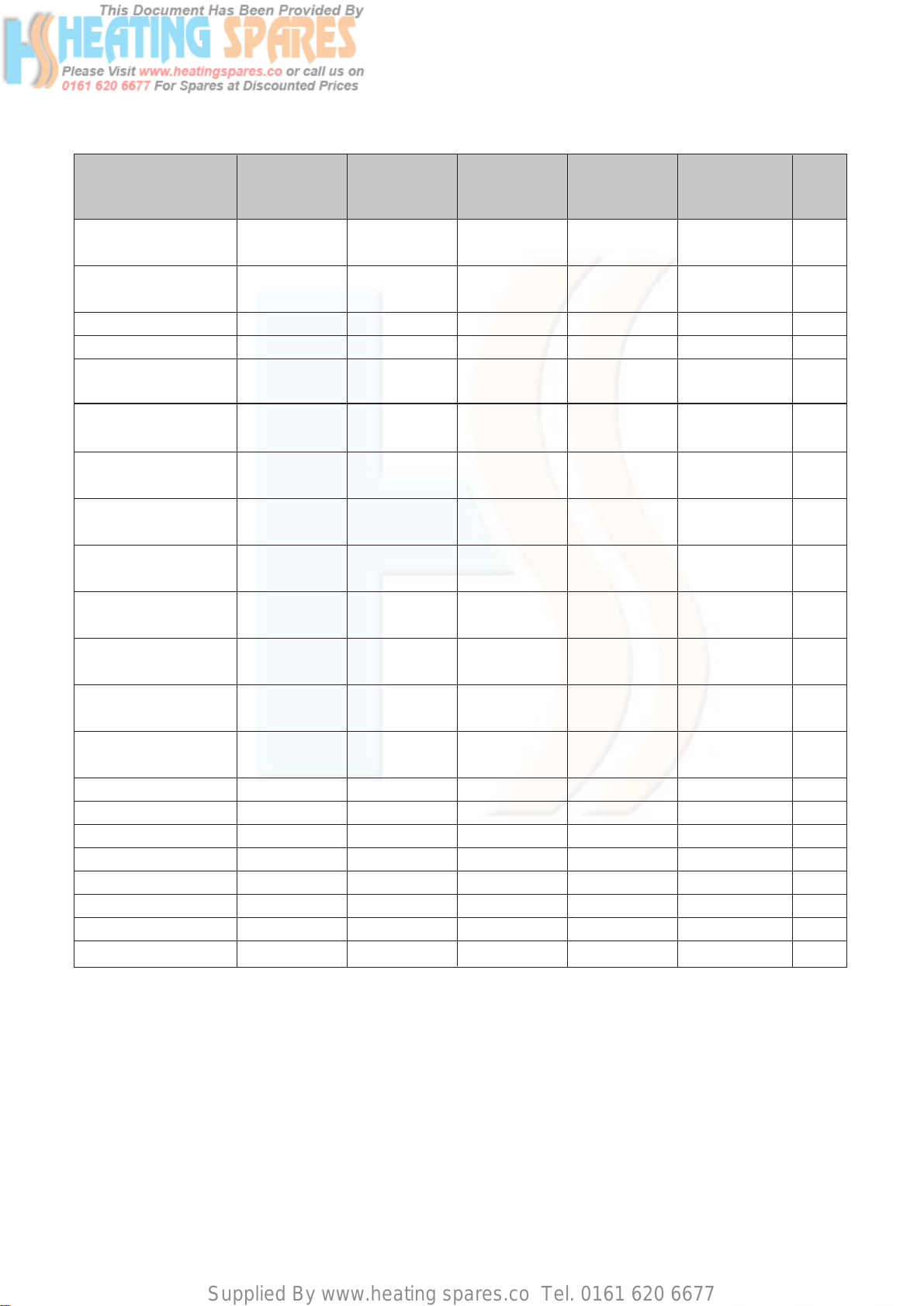
turboMAX plus turboMAX plus turboMAX plus
824/2 E 828/2 E 837 E Units
(VUW GB 242/2-5) (VUW GB 282/2-5) (VUW GB 362/2-5)
Maximum CH heat input (net) 26.7 (91,200) 31.1 (106,200) 31.1 (106,200) kW (Btu/h)
CH heat output range (80/60 °C) 8.9 - 24 10.4 - 28 10.9 - 28* (36,.9)
(30,400 - 81,900) (35,500 - 95,500) (37,200 - 95,500) kW (Btu/h)
Maximum DHW heat input (net) 26.7 (91,200) 31.1 (106,200) 40.5 (138,300) kW (Btu/h)
SEDBUK Band D D D
SAP Seasonal Efficiency 79.6 79.7 79.8 %
DHW heat output 24 28 36.9 kW
DHW flow rate ∆T = 35 °C rise 9.8 11.5 15.1 l/min
DHW flow rate at factory set
temperature rise (∆T 42 °C) 8.2 9.5 12.6 l/min
Mains water pressure required
for max. flow rate 0.5 0.5 0.5 bar
Minimum water flow rate 1.5 1.5 1.5 l/min
Mains water pressure required
for min. flow rate 0.15 0.15 0.15 bar
Maximum inlet water pressure 10 10 10 bar
Inlet gas working pressure
required (natural gas) 20 20 20 mbar
Gas supply (G20) Gross CV (s.t.) 37.8 37.8 37.8 MJ/m
3
Gas burner pressure max. rate 9.8 10.5 12.0 mbar
Gas burner pressure ignition rate 1.9 1.8 1.2 mbar
Gas rate max. (DHW) 2.8 3.3 4.3 m3/h
CH temperature flow range 35 - 82 35 - 82 35 - 82 °C
Minimum CH water flow
(for 20 °C rise) 1032 1203 1203 ** l/h
Pump pressure available 0.25 (25) 0.25 (25) 0.25 (25) bar (KPa)
Expansion vessel
pre-charge pressure 0.75 0.75 0.75 bar
Maximum CH system pressure 3 3 3 bar
Weight 43 45 48 kg
Primary water content 2.0 2.0 2.2 l
Electrical supply 230/50 230/50 230/50 V~/Hz
External fuse 3 3 3 A
Power input 150 150 130 W
Case height 800 800 800 mm
Case width 440 440 440 mm
Case depth 338 338 338 mm
3 Boiler Specification
3.1 Technical Data
* factory setting; ** at factory setting
Supplied By www.heating spares.co Tel. 0161 620 6677
Boiler Specification 3
Instructions for Installation and Servicing turboMAX plus and thermoCOMPACT R1 7
thermoCOMPACT thermoCOMPACT thermoCOMPACT thermoCOMPACT thermoCOMPACT
615/2 E 620/2 E 624/2 E 628/2 E 637 E Units
(VU GB 152/2-5) (VU GB 202/2-5) (VU GB 242/2-5) (VU GB 282/2-5) (VU GB 362-5)
Maximum CH heat input 16.5 22.0 26.7 31.1 40.5 kW
(net)(56,100) (74,800) (91,200) (106,200) (138,300) (Btu/h)
CH heat output range 6.5. - 15 7.7 - 20 8.9 - 24 10.4 - 28 10.5 - 36.9 kW
(80/60 °C) (22,300-51,200) (26,300 - 68,300) (30,400 - 81,900) (35,500 - 95,500) (35,800 - 126,000) (Btu/h)
SEDBUK Band D D D D D
SAP Seasonal Efficiency 79.0 79.7 79.7 79.8 79.8 %
Inlet gas working pressure
required (natural gas) 20 20 20 20 20 mbar
Gas supply (G20) 37.8 37.8 37.8 37.8 37.8 MJ/m
3
Gross CV (s.t.)
Gas burner pressure 9.9 9.0 9.8 10.5 12.0 mbar
max. rate
Gas burner pressure 2.2 1.5 1.9 1.8 1.2 mbar
ignition rate
CH temperature 35 - 82 35 - 82 35 - 82 35 - 82 35 - 82 °C
flow range
Minimum CH water flow
(for 20 °C rise) 650 860 1032 1203 1587 l/h
Pump pressure available 0.25 (25) 0.25 (25) 0.25 (25) 0.25 (25) 0.17 (17) bar
(KPa)
Expansion vessel
pre-charge pressure 0.75 0.75 0.75 0.75 0.75 bar
Maximum CH 3 3 3 3 3 bar
system pressure
Weight 38 39 41 43 45 kg
Primary water content 2.0 2.0 2.0 2.0 2.2 l
Electrical supply 230/50 230/50 230/50 230/50 230/50 V~/Hz
External fuse 3 3 3 3 3 A
Power input 150 150 150 150 130 W
Case height 800 800 800 800 800 mm
Case width 440 440 440 440 440 mm
Case depth 338 338 338 338 338 mm
Supplied By www.heating spares.co Tel. 0161 620 6677
3 Boiler Specification
Instructions for Installation and Servicing turboMAX plus and thermoCOMPACT R18
Key:
1Heating system return (22 mm tail)
2 Gas connection (15 mm tail)
3Heating system flow (22 mm tail, 22 mm for 637)
4 Flue outlet (100 mm flue with turret)
5 Hanging bracket
6Rear flue outlet
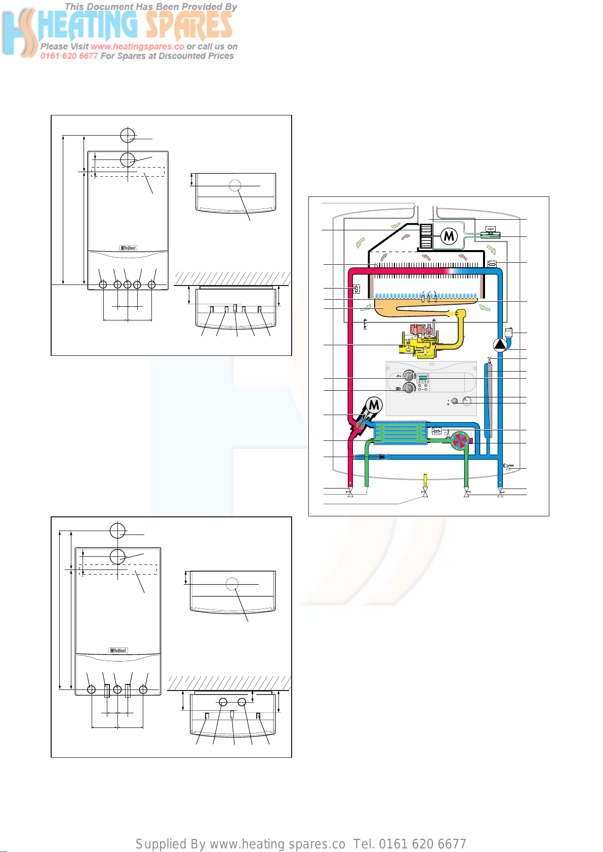
3.4 Functional Diagram (turboMAX plus)
Fig. 3.3: Functional Diagram turboMAX plus
Key:
1 Air duct
2Fan
3 Main heat exchanger
4Temperature sensor (NTC I)
5 Flame sensing electrodes
6 Modulating burner
7Fully modulating automatic gas value
8 Maximum hot water temperature control
9 Maximum radiator temperature control
10 Diverter valve
11 DHW heat exchanger
12 Automatic bypass valve
13 CH flow service valve
14 Hot water outlet
15 Gas service valve
16 Cold water service valve
17 CH return service valve
18 Pressure relief valve
19 Aqua sensor (DHW flow switch)
20 Temperature sensor (NTC III)
21 Main on/off control
u
C
C
i
1
2
3
4
5
6
7
8
9
10
11
12
13
14
15
17
16
18
19
20
21
22
23
24
25
26
27
28
29
30
31
3.2 Boiler connections (turboMAX plus)
Fig. 3.1: Connection diameters turboMAX plus
Key:
1Heating system return (22 mm tail)
2Cold water connection with shut off valve
(15 mm tail)
3 Gas connection (15 mm tail, 22mm for 837)
4Hot water connection (15 mm tail)
5Heating system flow (22 mm tail)
6 Flue outlet (100 mm flue with turret)
7 Hanging bracket
8Rear flue outlet
3.3 Boiler connections (thermoCOMPACT)
Fig. 3.2: Connection diameters thermoCOMPACT
7
543 21
102
6
8
264
638
902
145
6
5
100
100
55 55
432
130
180
1
80
6
100
8
145
7
130
5
432
264
102
902
638
543 21
35 35
100
6
180
1
Supplied By www.heating spares.co Tel. 0161 620 6677
Boiler Specification 3
Instructions for Installation and Servicing turboMAX plus and thermoCOMPACT R1 9
22 Pressure gauge
23 Display
24 Expansion vessel
25 Expansion vessel charging valve
26 Circulating pump
27 Automatic air vent
28 Ignition electrode
29 Temperature sensor (NTC II)
30 Air pressure switch
31 Flue gas duct
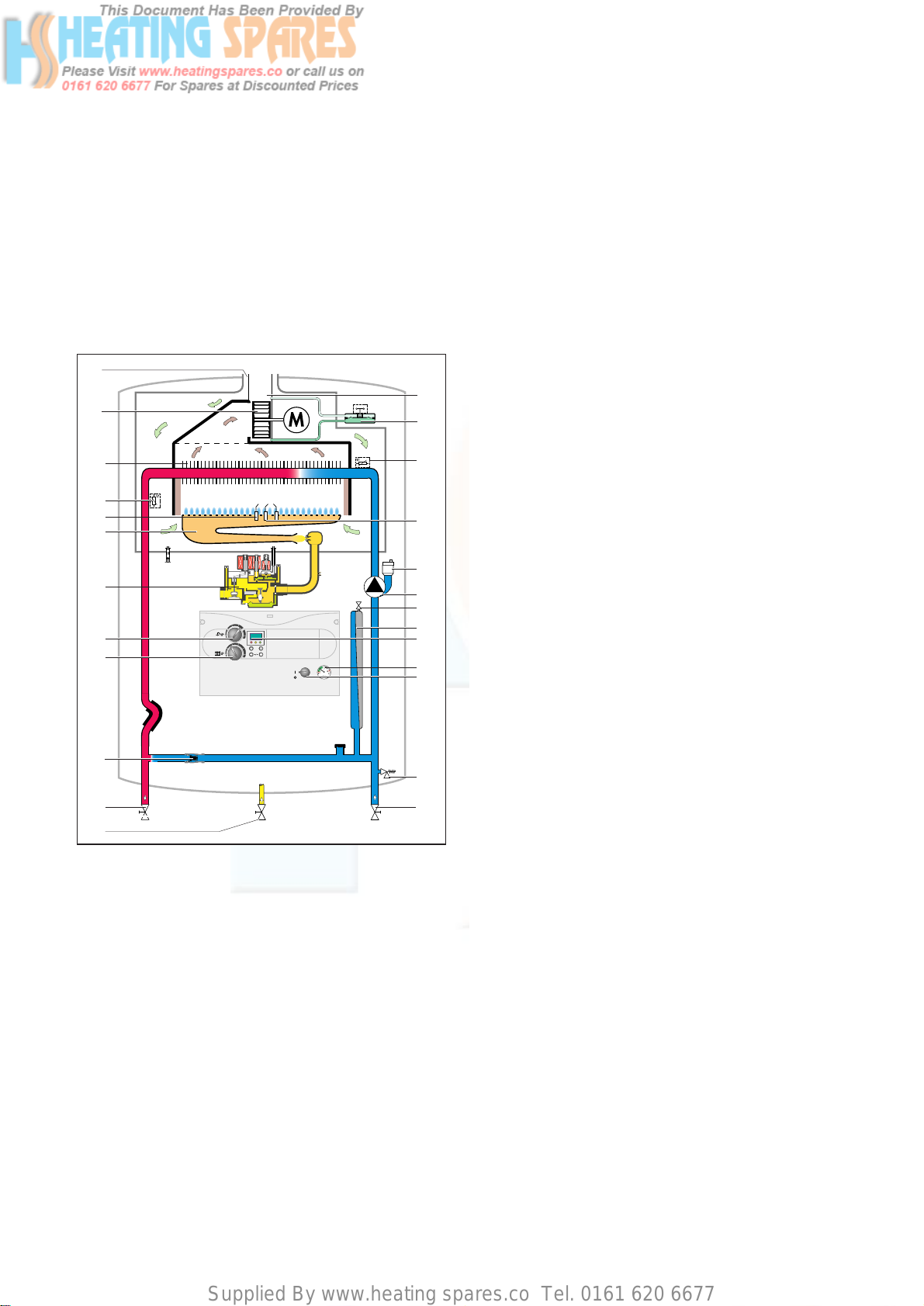
3.5 Functional Diagram (thermoCOMPACT)
Fig. 3.4: Functional Diagram thermoCOMPACT
Key:
1 Air duct
2Fan
3 Main heat exchanger
4Temperature sensor (NTC I)
5 Flame sensing electrodes
6 Modulating burner
7Fully modulating automatic gas value
8This control has no function on this boiler
9 Maximum radiator temperature control
10 Automatic bypass valve
11 CH flow service valve
12 Gas service valve
13 CH return service valve
14 Pressure relief valve
15 Main on/off control
16 Pressure gauge
17 Display
18 Expansion vessel
1
2
3
4
5
6
7
8
9
10
11
12
13
14
15
16
17
18
19
20
21
22
23
24
25
19 Expansion vessel charging valve
20 Circulating pump
21 Automatic air vent
22 Ignition electrode
23 Temperature sensor (NTC II)
24 Air pressure switch
25 Flue gas duct
Supplied By www.heating spares.co Tel. 0161 620 6677
4 General Requirements
4.2 Boiler location
The location chosen for the boiler must permit the
provision of a satisfactory flue termination. The location
must also provide adequate space for servicing and air
circulation around the boiler. The boiler may be installed
in any room, although particular attention is drawn to
the requirements of BS7671 (IEE Regulations), the
electrical provisions of the Building Regulations
(Scotland) and in IE the current edition of IS 813 and the
current ETCI rules, in respect of the installation of a
boiler in a room containing a bath or shower.
Note!
Where a room sealed boiler is installed in a room
containing a bath or shower, any electrical
switch or boiler control utilising mains
electricity should be so situated that it cannot
be touched by a person using the bath or
shower.
Where the installation of the boiler will be in an unusual
location, special procedures may be necessary and BS
5546 and BS 6798 give detailed guidance on this
aspect. The boiler must be mounted on a flat, vertical
wall, which must be sufficiently robust to take the
weight of the boiler. The boiler may be installed on a
combustible wall, subject to the requirements of the
Local Authorities and Building Regulations.
A compartment used to enclose the boiler must be
designed and constructed specifically for this purpose.
(An existing cupboard or compartment may be used
provided that it is modified for the purpose). Details of
essential features of cupboard/compartment design
including airing cupboard installations are given in BS
6891. In IE the current edition of IS 813.
If the boiler is to be fitted in a timber framed building, it
should be fitted in accordance with Institute of Gas
Engineers Publication IGE/UP/7/1998 "Guide for Gas
Installation in Timber Framed Housing“.
4.3 Gas Supply
The gas supplier should ensure the availability of an
adequate supply of gas.
A gas meter may only be connected to the service pipe
by the supplier of gas or their contractor.
An existing meter should be checked to ensure that it is
capable of passing the rate of gas supply required.
Installation pipes should be fitted in accordance with BS
6891. Pipework from the meter to the boiler must be of
an adequate size. Do not use pipes of a smaller size than
the boiler gas connection (15 mm, 22 mm for 837/637).
The complete installation must be tested for soundness
and purged as described in BS 6891.
Instructions for Installation and Servicing turboMAX plus and thermoCOMPACT R110
4 General Requirements
4.1 Related Documents
The installation of the boiler must be in accordance with
the relevant requirements of Gas Safety (Installation and
Use) Regulations 1998, Health and Safety Document No.
635 (The Electricity at Work Regulations 1989), BS7671
(IEE Wiring Regulations) and the Water Supply (Water
Fittings) Regulations 1999, or the Water Bylaws 2000
(Scotland). It should also be in accordance with the
relevant requirements of the Local Authority, Building
Regulations, Building Regulations (Scotland), Building
Regulations (Northern Ireland) and the relevant
recommendations of the following British Standard;
Including current amendments to Approved Documents
Part L and J.:
BBSS 55444400::
Flues and ventilation of gas fired boilers not
exceeding 70 kW net:
- Part 1: Flues
- Part 2: Ventilation
BBSS 55444499::
Specification for forced circulation hot water
for domestic premises.
BBSS 55554466::
Specification for gas hot water supplies for
domestic premises.
BBSS 66770000::
Services supplying water for domestic use
within buildings and their curtilages.
BBSS 66779988::
Specification for installation of gas fired
boilers not exceeding 70 kW input net.
BBSS 66889911::
Specification for installation of low pressure
gas pipework up to 28 mm (R1) in domestic premises
(2
nd
family gas).
BBSS 77559933::
Tre atment of water in domestic hot water
central heating systems.Institute of Gas Engineers
Publication IGE/UP/7/1998: Guide for Installation in
Timber Framed Housing. Benchmark Code of Practice.
Building Regulations Approved Documents Part L 2002
Part J 2002.
Important!
The appliance must be installed and serviced by
a competent person as stated in the Gas Safety
(Installation and Use) Regulations 1998. In IE,
the installation must be in accordance with the
current edition of IS 813 'Domestic Gas
Installations', the current Building Regulations
and reference should be made to the current
ETCI rules for electrical installation.
Preliminary remarks
This appliance should only be installed in conjunction
with a Vaillant flue system.
Install the flue system as detailed in the separate flue
installation instructions supplied with this boiler.
Supplied By www.heating spares.co Tel. 0161 620 6677
General Requirements 4
Instructions for Installation and Servicing turboMAX plus and thermoCOMPACT R1 11
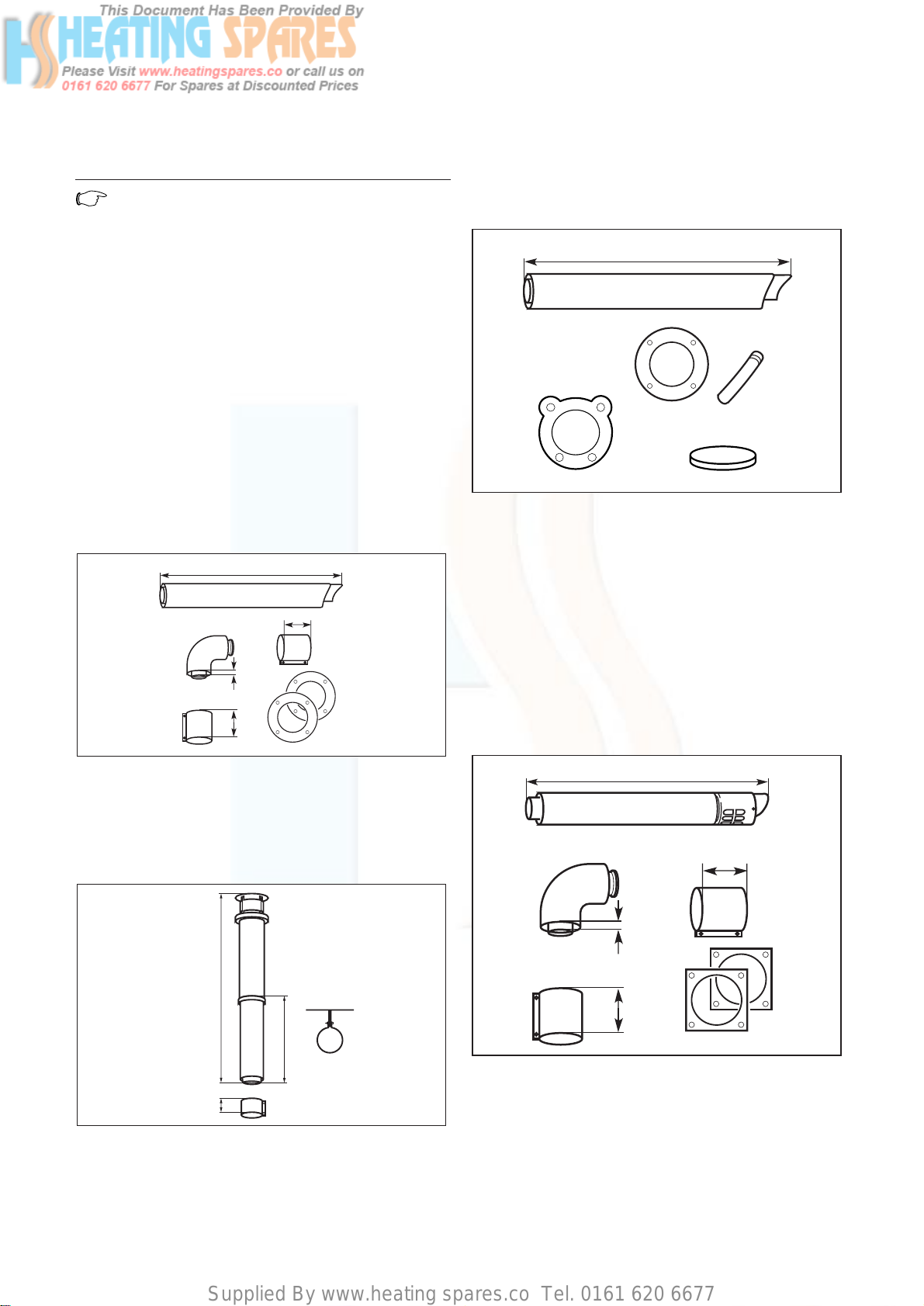
4.4.2 Rear outlet flue system
(100 mm outside diameter)
The rear outlet horizontal flue system (Art. No. 303 817)
is suitable for installations up to 600 mm wall thickness.
Fig. 4.3: Art.-No. 303 817
4.4.3 Extended top outlet flue system
(125 mm outside diameter)
A top outlet horizontal flue system of 125 mm outside
diameter is also available (Art. No. 303 609) and can be
used to achieve flue lengths of up to 12.9 m for 15/20/24
kW; 10 m for 28/37 kW.
Both 45° and 90° bends and elbows are also available to
increase siting flexibility.
A vertical 125 mm concentric flue system is also
available (Art. No. 303 600).
Refer to flue system installation instructions for full
details.
Fig. 4.4: Art.-No. 303 609
70
1103
70
15
4.4 Flue system
Note!
The boilers are delivered ready for installation
utilising a top outlet flue assembly. For
installation with a rear outlet flue assembly
refer to the boiler flue outlet adaptation in the
flue instructions.
4.4.1 Top outlet flue system
(100 mm outside diameter)
The top outlet horizontal flue system (Art. No. 303 807)
is suitable for installations up to 720mm measured
from the centre of the boiler flue outlet to the outside
face of the wall. Flue extensions are available to extend
this length up to 5.3 m for 15/20 kW; 4.5 m for 24 kW
and 3.2 m for 28/37 kW.
Both 90° bends and 45° elbows are also available to
increase siting flexibility.
A vertical flue system is also available (Art. No. 303
800).
Refer to flue system installation instructions for full
details.
Fig. 4.1: Art.-No. 303 807
A vertical flue system is also available (Art. No. 303
800).
Refer to flue system installation instructions for full
details.
Fig. 4.2: Art.-No. 303 800
48
1285
603
750
48
4
48
750
Supplied By www.heating spares.co Tel. 0161 620 6677
4 General Requirements
1) In addition, the terminal should not be nearer than 150mm to an
opening in the building fabric formed for the purpose of
accommodating a built-in element such as a window.
* BS 5440-1 It is recommended that a fanned flue terminal should
be positioned as follows: a) at least 2m from an opening in a
building directly opposite, and b) so that the products of
combustion are not directed to discharge across a boundary.
4.5 Air supply
Detailed recommendations for air supply are given in BS
5440: Part 2.
It is not necessary to have an air vent in the room or
internal space in which the boiler is installed.
4.6 Cupboard or compartment ventilation
The boilers are very high efficiency appliances. As a
consequence the heat loss from the appliance casing
during operation is very low. For cupboard or
compartment installations it is therefore not necessary
to provide any high or low level permanent air vents for
cooling purposes.
4.7 Electrical supply
A 230 V, ~ 50 Hz single phase electricity supply fused to
3 Amp. must be provided in accordance with the latest
edition of BS7671 (IEE Wiring Regulations) and any other
local regulations that may apply. In IE, reference should
be made to the current edition of the ETCI rules.
The method of connection to the mains electricity
supply must provide a means of completely isolating the
boiler and its ancillary controls. Isolation is preferably by
the use of a fused three pin plug and unswitched
shuttered socket outlet, both complying with the
Instructions for Installation and Servicing turboMAX plus and thermoCOMPACT R112
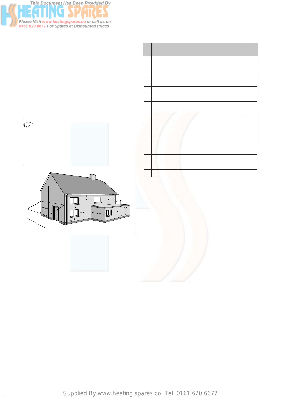
4.4.4 Flue termination
The following details refer to both flue systems.
a. The terminal must be positioned such that the pro-
ducts of combustion can disperse freely at all times.
b. In certain weather conditions a plume of water
vapour may be visible from the flue terminal.
Positions where this could be a nuisance should be
avoided.
c. If the terminal is fitted less than 2 m above a
balcony, above ground or above a flat roof to which
people have access then a suitable terminal guard;
must be provided and fitted (Model K3 - made by
Tower Flue Components, Tonbridge, TN9 1TB).
Note!
Vertical flues must not terminate within
600 mm of an openable window, air vent or any
other ventilation opening.
The flue assembly shall be so placed or shielded as to
prevent ignition or damage to any part of the building.
Fig. 4.5: Flue termination
A
BCD
A
G
H, I
F
J
B
F
M
L
L
K
K
G
G
F
F
E
A
A
Terminal position for fan-assisted flue
(minimum distance) mm
A1)Directly below an openable, above an opening
or horizontal to an opening i.e. air brick, opening
window or other, etc 300
BBelow gutters, soil pipes or drain pipes 25
CBelow eaves 25
DBelow balconies (below car port roof) 25
EFrom vertical drain pipes and soil pipes 25
FFrom internal or external corners 25
G Above ground or balcony level 300
HFrom a surface or boundary facing a terminal 600*
HFrom a terminal facing a terminal 1200
JFrom an opening in a car port (e.g. door, window)
into a dweling 1200
KVertically from a terminal on the same wall 1500
L Horizontally from a terminal on the same wall 300
M Distance from adjacent wall for vertical Flue 500
Supplied By www.heating spares.co Tel. 0161 620 6677
General Requirements 4
Instructions for Installation and Servicing turboMAX plus and thermoCOMPACT R1 13
(Alternative methods of filling sealed systems are given
in BS 5449).
4.8.3 Pressure relief valve
A pressure relief valve is provided with the boiler. This
safety device is required on all sealed C.H. systems and
is preset at 3 bar and provided with a 15 mm
compression connection for a discharge pipe, which
must be of no less than 15 mm in diameter. The Pressure
Relief Valve must not be used for draining purposes.
4.8.4 Pressure gauge
This is factory fitted to the boiler and indicates the
primary circuit pressure to facilitate filling and testing.
4.8.5 Expansion vessel
The 15 and 20 kW thermoCOMPACT boilers as well as
the 24 kW turboMAX plus boiler incorporate a 6 litre
expansion vessel which is suitable for a sealed heating
system with a maximum water content of 60 litres. A
10 litre expansion vessel kit is available as an optional
accessory for for the turboMAX plus 24 kW boiler and
the 15 and 20 kW thermoCOMPACT boilers.
The 28, 37 turboMAX plus and 24, 28, 37 kW
thermoCOMPACT boilers incorporate a 10 litre expansion
vessel which is suitable for a sealed heating system with
a maximum water content of 100 litres.
If the nominal capacity of the built in expansion vessel is
not sufficient for the heating system (for instance in
case of modernization of old open systems) an
additional expansion vessel can be installed external to
the boiler. It should be fitted in the return pipe as close
as possible to the boiler in accordance with BS 5449:
Part 1.
Guidance on the sizing of an additional expansion vessel
is given in Table on page 14.
requirements of BS 1363. Alternatively, a 3 Amp. fused
doublepole switch with a 3 mm contact separation on
both poles may be used.
Important!
This appliance must be earthed.
4.8 Guide to system requirements
4.8.1 Water circulation system
Detailed recommendations for the water circulation
system are given in BS 6798 and BS 5449: Part 1 (for
small bore and micro bore central heating systems).
Pipework not forming part of the useful heating surface
should be insulated to help prevent heat loss and
possible freezing, particularly where pipes are run
through roof spaces and ventilated underfloor spaces.
Draining taps must be located in accessible positions
which permit the draining of the whole system including
the boiler and the hot water system. Draining taps
should be at least 1/2 in. BSP nominal size and be in
accordance with BS 2879.
The boiler is suitable for use with minibore or microbore
systems. Copper tubing to BS 2871: Part 1 should be
used for water carrying pipework. All capillary joints in
all DHW pipework must be made with lead free solder.
Particularly where a new boiler is to be fitted to an
existing system, it is good practice that the system is
thoroughly cleansed. This cleansing should take place
prior to the fitting of the new boiler and be in
accordance with BS 7593.
For advice on the application of system cleansers
contact either Sentinel, GE Betz. Widnes, Cheshire,
WA8 8UD.
Tel: 0151 420 9595
or:
Fernox
Alpha-Fry Technologies
Tandem House
Marlow Way, Beddington Farm Road
Croydon CRO 4xS
Tel. 0870 601 5000
Fernox technical
help line 01799 550811
4.8.2 Filling and make up
The system can be filled using the built in filling loop
(turboMAX plus only) or via a separate filling point fitted
at a convinient position on the heating circuit
(thermoCOMPACT). The connection must be removed
when filling is completed. Where local Water Authority
regulation does not allow temporary connection, a
sealed system filler pump with break tank must be used.
The heating system will not be filled automatically from
the domestic hot water side.

Supplied By www.heating spares.co Tel. 0161 620 6677
4 General Requirements
Fig. 4.6: Pump specifications 37 kW
4.8.7 System by-pass
An automatic system by-pass is included within the
boiler. The boiler is suitable for use in systems with
thermostatic radiator valves and no additional by-pass is
required.
4.8.8 Venting
The boiler is fitted with an automatic air vent. Additional
provision should be made to enable the heating system
to be vented during filling and commissioning either by
automatic air vents or manually.
0 100 200 300 400 500 600 700 800 900 1000 1100 1200 1300 1400
50
100
150
200
250
300
350
400
450
500
550
600
650
700
Volume flow [l/min]
Lift [mbar]
Pump switch in position III (pre-delivery setting)
Pump switch in position II
1500 1600 1700
Instructions for Installation and Servicing turboMAX plus and thermoCOMPACT R114
4.8.6 Circulating pump
The circulating pump is included in the boiler. The pump
head available for the heating system is shown in
fig. 4.6.
Fig. 4.6: Pump specifications 12-28 kW
0 100 200 300 400 500 600 700 800 900 1000 1100 1200 1300 1400
50
100
150
200
250
300
350
400
450
500
550
600
650
700
Volume flow [l/hr]
Lift [mbar]
Pump switch in position III (Factory setting)
Pump switch in position II
Vessel Volume [L]
Initial system pressure (bar) 1.0 1.5
Pressure relief valve setting (bar) 3.0
To tal water content of system ltres
25 2.7 3.9
50 5.4 7.8
100 10.9 15.6
125 13.6 19.5
150 16.3 23.4
175 19.1 27.3
200 21.8 31.2
225 24.5 35.1
250 27.2 39.0
275 30.0 42.9
30032.7 46.8
325 35.7 50.7
350 38.1 54.6
375 40.958.5
400 43.6 62.4
425 46.3 66.3
450 49.0 70.2
475 51.8 74.1
500 54.5 78.0
For system volumes other than those given
above, multiply the system volume by the
factor across 0.109 0.156
Supplied By www.heating spares.co Tel. 0161 620 6677
Boiler Installation Sequence 5
Instructions for Installation and Servicing turboMAX plus and thermoCOMPACT R1 15
Selecting position of boiler
Refer to "Boiler location“ for information regarding
siting the appliance. In general the boiler must be
positioned such that.
•There is adequate space around the boiler for service
and maintenance.
•The boiler can be correctly flued, i.e. the flue terminal
position is sited in accordance with the flue
termination section and the air/flue duct can be
installed in accordance with the flue installation
instructions supplied.
• All necessary pipework can be connected, including
the pressure relief valve.
Note!
Should it be necessary to run system pipework
to above the boiler within the width of the
casing, use the optional top connection
accessory (Art.No. 306 251).
5 Boiler Installation Sequence
5.1 General
Preparation of boiler location
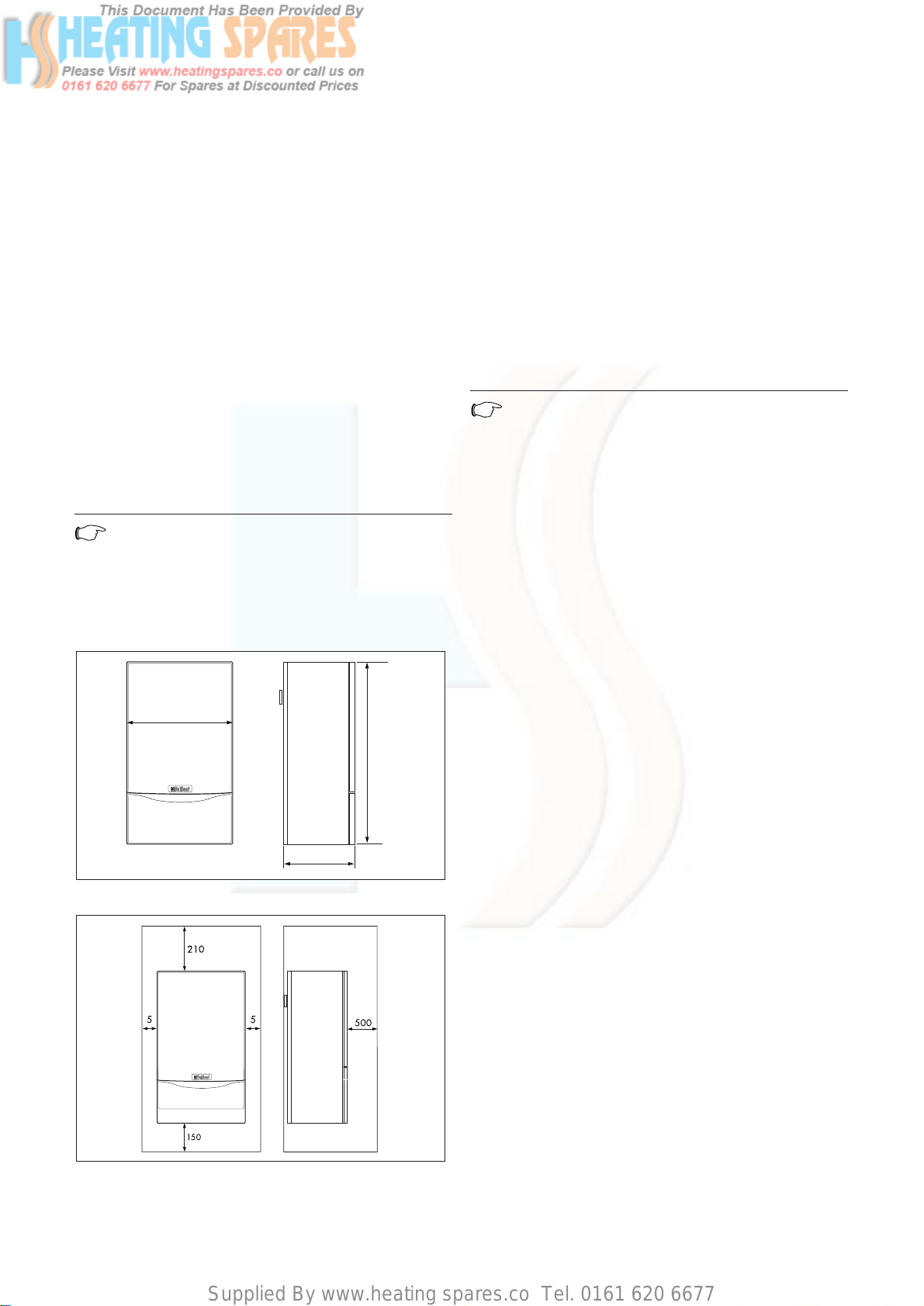
Clearances required
Mount the boiler on a flat and vertical area of wall of
sufficient area for the boiler plus the required
clearances for installation and servicing.
The clearances are as detailed below and are shown on
the installation template supplied with the boiler:
- 150 mm below the boiler
- 5 mm on either side of the boiler
- 210 mm on top of the boiler
- 500 mm in front of the boiler*
* Clearance is only required to enable easier access to
the boiler for servicing and may be provided by an
openable door, etc.
Note!
If the boiler is to be fitted in a timber framed
building, it should be fitted in accordance with
Institute of Gas Engineers Publication
IGE/UP/7/1998 "Guide for Gas Installations in
Timber Framed Dwellings“.
Fig. 5.1: Dimensions of boiler
Fig. 5.2: Free space required for installation
440
800
338
Supplied By www.heating spares.co Tel. 0161 620 6677
5 Boiler Installation Sequence
Note!
Use alternative fixing holes where necessary.
Identify correct flue exit
Mark the centre of the selected air/flue duct and its
circumference, e.g. by drilling through the template. For
installation of a rear exit outlet please refer to the
installation instructions of the rear exit outlet kit
(Art. No. 303 817).
Other flue options
Flue instructions for other flue systems such as vertical
RSF flues, flues run to the side of the boiler and the use
of additional bends etc. are detailed in the flue
installation instructions provided with the boiler.
Remove the template from the wall and plug the drilled
holes using the wallplugs supplied.
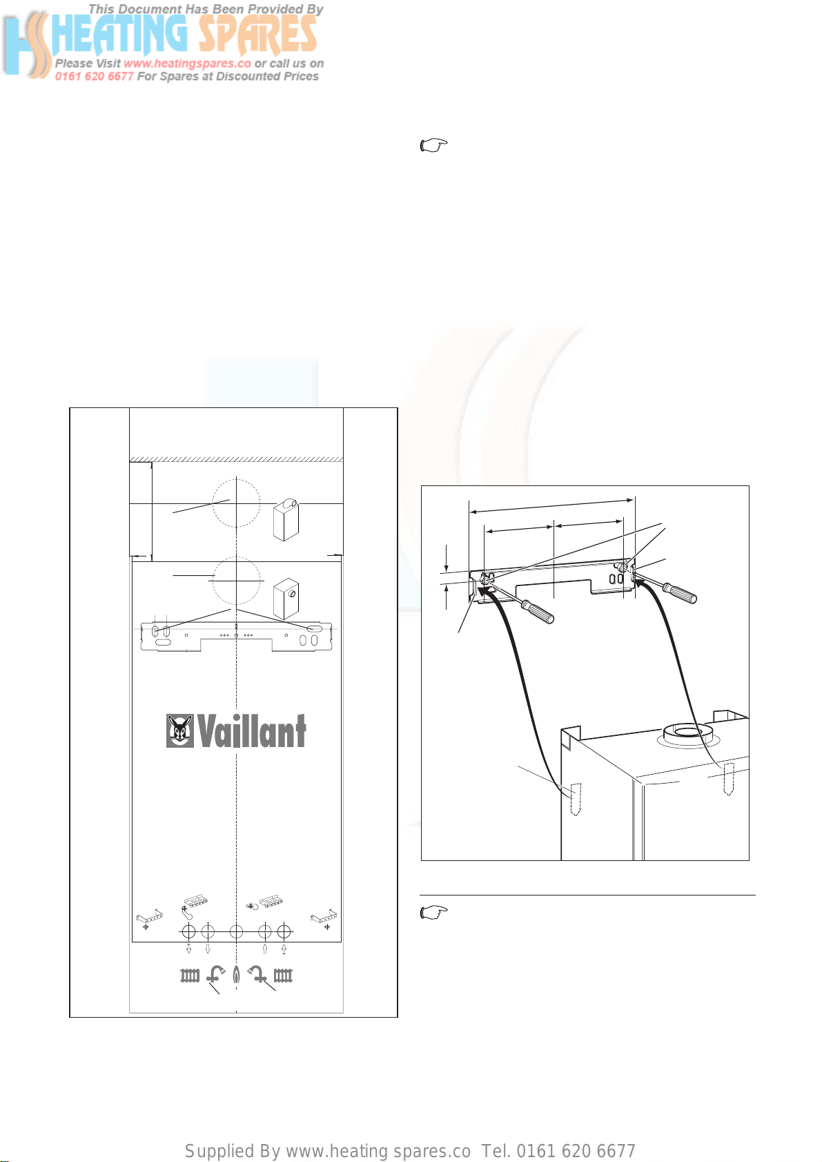
5.3 Fitting the boiler hanging bracket
Fix the hanging bracket (1) to the wall using the screws
supplied (2). (it may be necessary to use additional or
alternative fixings to ensure adequate support).
Fig. 5.4: Free space required for installation
Note!
If the boiler is to be fitted in a timber framed
building ensure that the bracket is secured to a
substantial part of the timber frame capable of
taking the weight of the boiler.
3
402
171
174,5
12,5
1
1
2
Instructions for Installation and Servicing turboMAX plus and thermoCOMPACT R116
5.2 Using boiler template
Fix the paper template to the wall ensuring that the
correct flue exit point has been identified, ensure that
the template is vertical.
The template shows
- The position of the fixing holes for the boiler
mounting bracket (1).
- The position of the connections.
- The position of the flue exit hole.
- Upper hole (2) indicates top outlet flue with flue
turret facing rearward.
- Lower hole (3) indicates rear outlet flue exiting
directly through wall.
• Mark the position of the hanging bracket fixing holes
(1).
• Drill 2 holes Ø 8 mm for the hanging bracket.
Fig. 5.3: Using Boiler template
5
5
210
124163 21200/202/240/242/280/282/824/828 Pro/Plus
60/100
07/2002
210
2
3
1
turboMAX only
Supplied By www.heating spares.co Tel. 0161 620 6677
Boiler Installation Sequence 5
Instructions for Installation and Servicing turboMAX plus and thermoCOMPACT R1 17
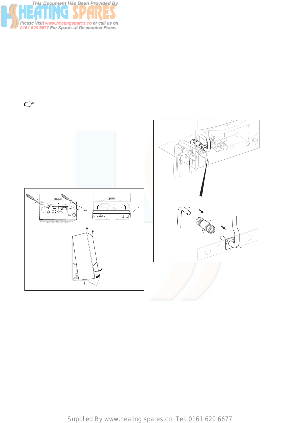
5.7 Gas supply (turboMAX plus)
•Connect the 15 mm compression gas service cock (1)
and 15 mm copper outlet tail (22mm copper tail with
837) (3) as supplied with the appliance (2) and tighten.
•Connect a gas supply pipe of not less than 15 mm
diameter to the copper tail (minimum 22 mm gas
supply pipe with 837).
•Tighten all connections.
(Ensure the gas supply pipework is adequately sized
such that a 20 mbar gas pressure is available at the
boiler inlet at full flow rate).
Fig. 5.6: Fitting the gas connection turboMAX plus
I
0
3
1
2
5.4 Install the flue system
Fit the flue restrictor to the boiler (if required) and
install the flue system (refer to separate air/flue duct
installation instructions for further information).
5.5 Fitting the boiler
• Lift the boiler (3) up to the wall so that it is slightly
above the hanging bracket (1).
Note!
Lift the boiler from either side at the bottom
edge.
•Lower the boiler slowly onto the hanging bracket so
that the cross member at the rear of the boiler fully
engages onto the hanging bracket.
5.6 Removing boiler casing
•Turn both securing fasteners (1) anti-clockwise by 90°
to release control panel (2).
• Pull the case (3) forward at the bottom to disengage
from the securing clips.
• Lift the case slightly to clear the top locations and pull
forward to remove.
Fig. 5.5: Remove of boiler casing
VRC-VC
3
I
0
2
I
0
90°90°
1
Supplied By www.heating spares.co Tel. 0161 620 6677
5 Boiler Installation Sequence
5.9 Central heating flow and return pipework
(turboMAX plus)
Before connecting the heating circuit to the boiler
appliance, all pipework and radiators must be thoroughly
flushed to remove any installation debris.
•Connect the central heating flow (6) and return (1)
service valves to the appliance (8 and 3) with the
washers provided (2 and 7) and tighten the nuts.
Ensure that the valve spindles face downwards and
the drain points face to either side of the boiler.
•Connect the 22 mm copper pipe tails to the service
valves as shown in the illustration and tighten the
nuts.
•Connect the central heating pipework to the flow (9)
and return (4) tails.
Pressure Relief Valve
Connect a discharge pipe not less than 15 mm diameter
to the outlet of this valve.
The discharge pipework should be as short as possible
and installed with a continuous fall away from the boiler.
The pipe should terminate in a position which ensures
that any discharge of water or steam from the valve
cannot create a hazard to persons in or about the
premises, or cause damage to any electrical components
or external wiring, and the point of discharge should be
clearly visible (see diagram in plastic bag).
Fig. 5.8: Central heating flow and return pipework turboMAX
plus
9
I
0
4
1
2
3
8
7
6
Instructions for Installation and Servicing turboMAX plus and thermoCOMPACT R118
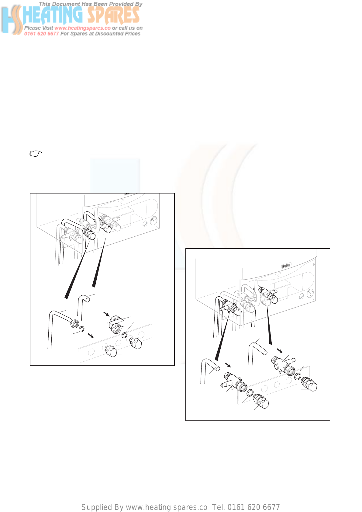
5.8 Cold water mains inlet and hot water outlet
(turboMAX plus)
Flush all foreign matter from the mains supply before
connecting to the boiler.
•Connect the cold water service valve (1) to the cold
inlet water connection (3) of the appliance with the
washer (2) provided and tighten.
•Connect the 15 mm cold water inlet pipe copper tail
(4) to the cold water service valve (1) and tighten.
•Connect the 15 mm hot water outlet copper tail (6) to
the hot water outlet connection of the appliance (8)
with the washer provided (7) and tighten.
Note!
The hot water outlet union nut is packed in with
the PRV fitting pack.
•Connect the cold water service pipe and hot water
outlet pipework to the copper tails.
Fig. 5.7: Fitting the hot and cold water connections turboMAX
plus
1
2
3
4
6
7
8
I
0

Supplied By www.heating spares.co Tel. 0161 620 6677
Boiler Installation Sequence 5
Instructions for Installation and Servicing turboMAX plus and thermoCOMPACT R1 19
5.11 Central heating flow and return pipework
(thermoCOMPACT)
Before connecting the heating circuit to the boiler
appliance, all pipework and radiators must be thoroughly
flushed to remove any installation debris.
•Connect the central heating flow (6) and return (1)
service valves to the appliance (8 and 3), with the
washers (2 and 7) provided and tighten the nuts.
Ensure that the valve spindles face downwards and
the drain points face to either side of the boiler.
•Connect the 22 mm copper pipe tails to the service
valves as shown in the illustration and tighten the
nuts.
•Connect the central heating pipework to the flow (9)
and return (4) tails.
Pressure Relief Valve
Connect a discharge pipe not less than 15 mm diameter
to the outlet of this valve.
The discharge pipework should be as short as possible
and installed with a continuous fall away from the boiler.
The pipe should terminate in a position which ensures
that any discharge of water or steam from the valve
cannot create a hazard to persons in or about the
premises, or cause damage to any electrical components
or external wiring, and the point of discharge should be
clearly visible (see diagram in plastic bag).
Fig. 5.10: Central heating flow and return pipework
thermoCOMPACT
9
I
0
4
1
2
3
8
7
6
5.10 Gas supply (thermoCOMPACT)
•Connect the 15 mm compression gas service cock (1)
and 15 mm copper outlet tail (22 mm copper tail with
637) (3) as supplied with the appliance and tighten.
•Connect a gas supply pipe of not less than 15 mm
diameter to the copper tail (minimum 22 mm with
637).
•Tighten all connections.
(Ensure the gas supply pipework is adequately sized
such that a 20 mbar gas pressure is available at the
boiler inlet at full flow rate).
Fig. 5.9: Fitting the gas connection thermoCOMPACT
I
0
3
1
2
Supplied By www.heating spares.co Tel. 0161 620 6677
5 Boiler Installation Sequence
Fig. 5.11: Wiring system
Fig. 5.12: Exposed rear view of switchgear cabinet (picture
shows turboMAX appliance)
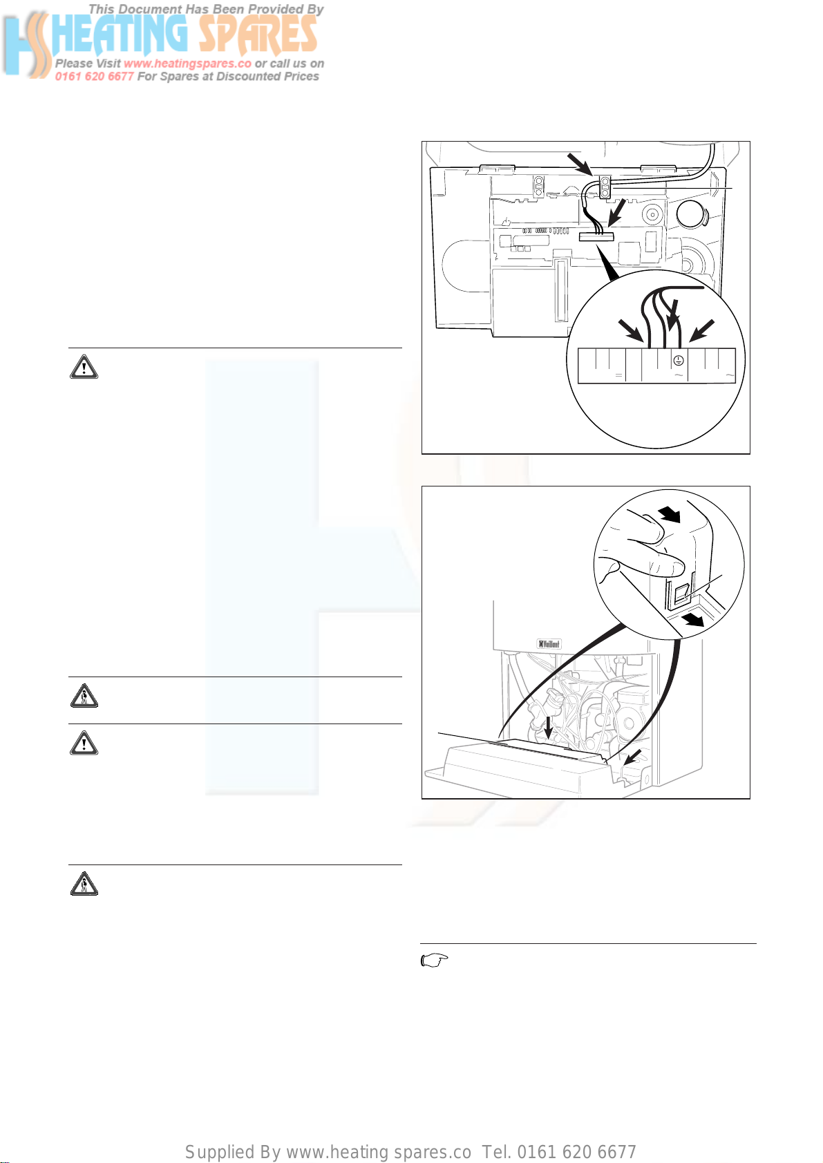
•Connect the power supply cord as follows (Fig. 5.13).
Green/yellow (earth) wire: boiler terminal Earth sign
Blue (neutral) wire: boiler terminal N
Brown (live) wire: boiler terminal L
Note!
DO NOT use boiler terminal connections 7-8-9.
•Refit the terminal box cover by pushing into place
until it clips back into position.
•Raise the control panel and secure in place.
2
1
Instructions for Installation and Servicing turboMAX plus and thermoCOMPACT R120
5.12 Connection to a VANTAGE unvented cylinder
(thermoCOMPACT)
•For connecting a Vaillant VANTAGE unvented cylinder
please refer to the VANTAGE installation instructions
provided with the cylinder.
5.13 Connect the flue system to the boiler
•Refer to separate air/flue duct installation instructions
included with the boiler.
5.14 Electrical installation
General requirements
Important!
All electrical work shall be carried out by a
competent person and shall comply with
BS7671 (IEE Regulations).
The boiler is supplied for connection to 230 V, ~ 50 Hz
supply fused at 3 A rating.
Connection to the mains supply shall be made via a
fused 3 pin plug to an unswitched shuttered socket,
both complying to the requirements of BS1363.
(Alternatively, connection may be made via a 3 A fused
double pole isolator having a contact separation of at
least 3 mm in all poles and supplying the boiler and
controls only).
The point of connection to the mains supply must allow
complete electrical isolation of the boiler and its
ancillary controls. It should be readily accessible and
adjacent to the boiler. A 3 core flexible cord according
to BS6500 tables 6, 8 or 16 (3 x 0.75 to 3 x 1.5 mm
2
)
should be used.
Warning!
This appliance must be earthed.
Important!
Ensure that all cords pass through the cable
clamps in the rear of the control box and are
securely fixed. Ensure that the power supply is
connected such that the current carrying
conductors become taut before the earth
conductor should the supply cord slip from the
cable clamp.
Warning!
Mains connection terminals L and N remain live
even when the boiler on/off control is switched
off.
5.15 Connection to the main supply
•Lower the control panel.
• Unclip the terminal box cover (1) from the control
panel.
•Feed the power supply cord in to the appliance as
shown (fig 5.11).
•Use cable clamps.
3
RT 24V 230V RT 230V
NL987543
Supplied By www.heating spares.co Tel. 0161 620 6677
Boiler Installation Sequence 5
Instructions for Installation and Servicing turboMAX plus and thermoCOMPACT R1 21
Abb. 0.0 Bildunterschrift
Fig. 5.13: Connection wiring
NL987
F3
543
24V
230V
F1
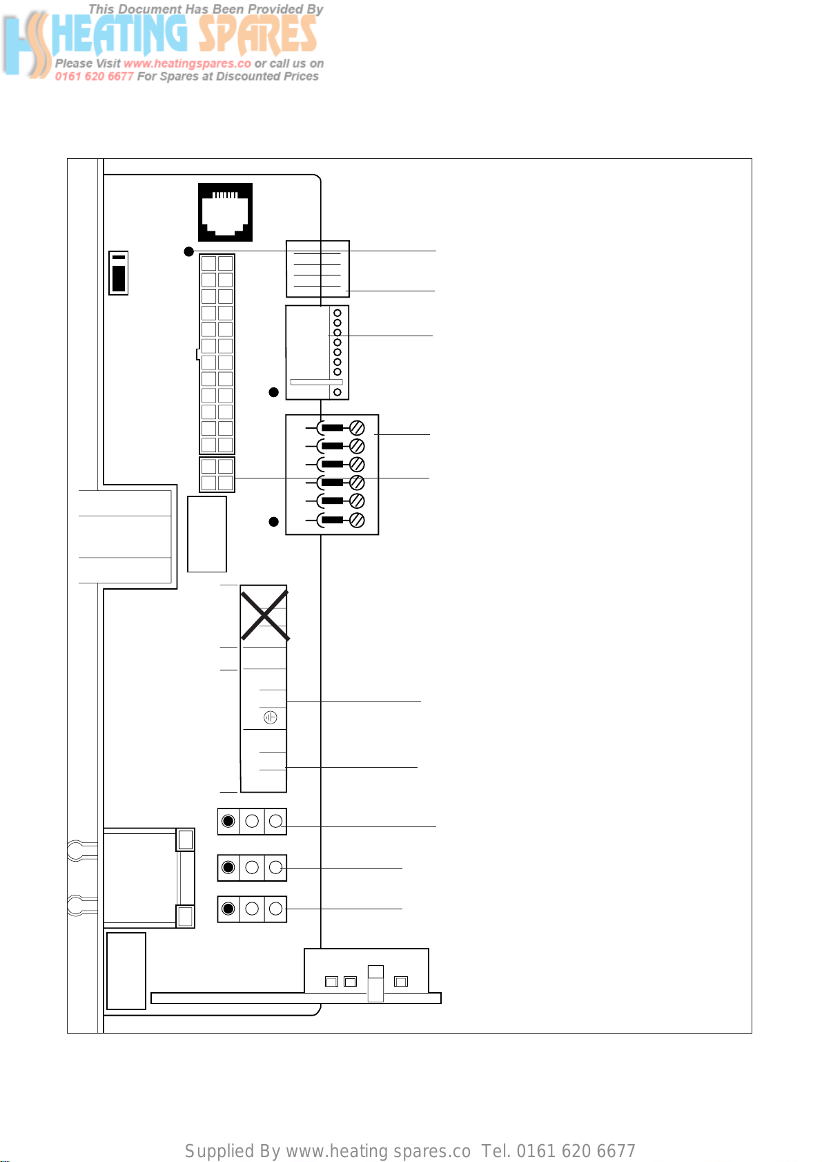
5.16 Electronic board layout
Socket X2 for internal unit components
Socket X4 for diverter valve
Socket X7 for accessory box connection
Socket X8 for VRC-VC connection
Room thermostat, 230 V: connections 3, 4 and 5
Mains power supply: connections L, N and earth
Socket X12: pump connection
Socket X14: gas valve connection
Socket X13: fan connection
Do not use!
Socket for fan control cable (637 and 837 only)
Supplied By www.heating spares.co Tel. 0161 620 6677
5 Boiler Installation Sequence
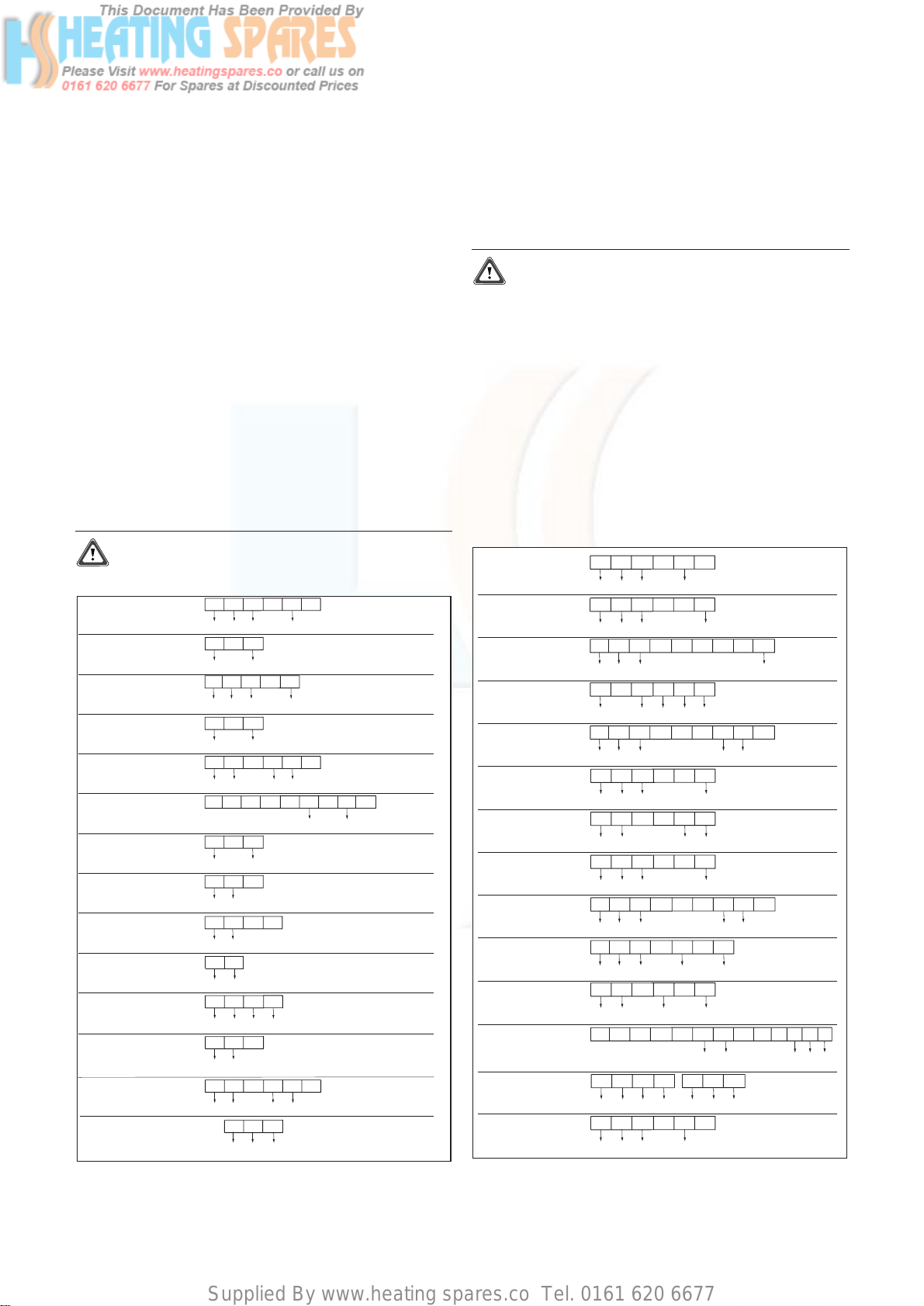
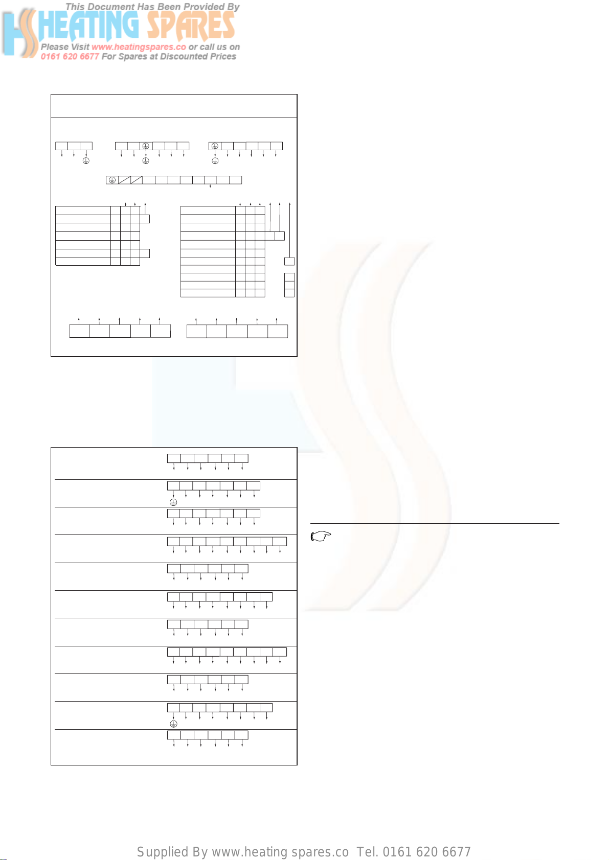
Connection details for external time switches and
boiler terminal strip.
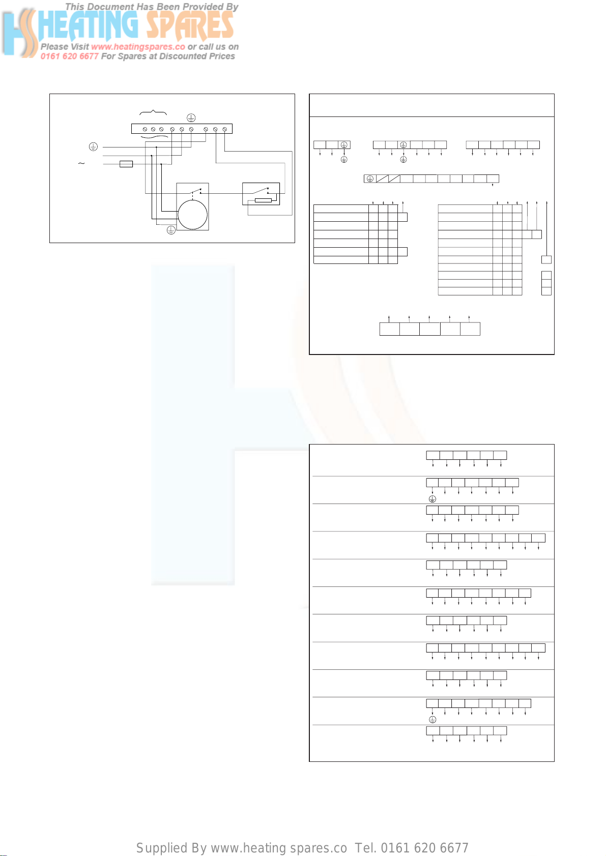
Fig. 5.15 shows the connection details where a time
switch is used without a room thermostat to control the
boiler.
Attention!
The arrowed numbers indicate connection into
the relevant terminal in the boiler terminal strip.
If a room thermostat is to be connected in addition to a
time switch the wire between the time switch "ON“
terminal and boiler terminal 4 should be broken by the
contacts of the room thermostat (see schematic layout,
Fig. 5.16).
Vaillant optional plug in timer accessories
Refer to the instructions supplied with the optional
accessories for connection details.
Upon completion of all electrical connections refit the
terminal box cover by pushing into place. The cover is
secured by two locking clips.
Instructions for Installation and Servicing turboMAX plus and thermoCOMPACT R122
Fig. 5.15 Connection details for time switch
LN
234
LN3
4
1
ACL Drayton
Tempus 1, Tempus 2
Lyfestyle LP111, LP711
ACL Drayton
Switchmaster
SM300
ACL Drayton
Switchmaster 980
Danfoss Randall
103 Series
Danfoss Randall
Set 1E, TS975
Danfoss Randall
TS715
Grässlin Towerchron
QE1, QM1
Honeywell
ST610A, ST6100C
Horstmann
Channel Plus
H11, H17, 425 Coronet
Horstmann
Centaur Plus
C11, C17
LN
234
LN4
3
1
Potterton Myson
EP 4002, EP 5002
Smiths Timeguard
SupplyMASTER
FST11, FST17
Sunvic
Select 107
N1
AB C
N4
2
L
L
3
34
12
65E
4L3
N
3
E
NE
234
NE
1
L
L
3
56
4
LN
234
LN3
4
1
LN
234
LN 3
4
1
LN
234
LN3
4
1
NE
234
NE
1
L
L
3
56
4
NE
234
NE
1
L
L
3
4
LN
234
LN 3
4
1
LN
234
LN3
4
1
AB
DL N
LN
C
N
E
3
12
4
345E
12
4
432/L
1/N
3
65
mains supply
LNE
E
Landis & Staefa
RWB7, RWB30
5.17 Controls (turboMAX plus boiler)
External electrical controls
The boiler terminals 3, 4 and 5 are for connecting
external electrical controls such as a time switch and/or
room thermostat.
Te rminals 3 and 4 are linked together when the boiler is
supplied. If external controls are used, this link must be
removed and the controls connected across terminals 3
and 4.
Terminal 5 is an additional neutral connection for
external neutrals such as from the anticipator of a room
thermostat.
Connection of external controls
Connection details for programmable room
thermostats.
Fig. 5.14 shows the connection details where a
programmable room thermostat (time switch with built
in room thermostat) is used to control the boiler.
Attention!
The arrowed numbers indicate connection into
the relevant terminal in the boiler terminal strip.
Fig. 5.14 Connection details for programmable thermostats
LN
234
LN3
4
1
ACL Drayton
Lyfestyle PT271, PT371
ACL Drayton
Digistat 2, 3, 4
ACL Drayton
Digistat RF - SCR Receiver
Danfoss Randall
TP4, TP5, TP5E
Danfoss Randall
TP5E RF with receiver RX1
Danfoss Randall
TP75
Grässlin Towerchron
RTC7
Honeywell
CM61, CM67, CM31, CM37
Horstmann
Centaurstat 1, 7
Landis & Staefa
REV 11, REV 15, REV 22
12
34
3
Sunvic
TLX 6501
Sunvic
TLX RFP, TLX RFD
Vaillant
VRT 230, 220
N1
3
N3
2
L
L
4
32
43
1
LN
234
LN 3
4
1
BC
2341
A
3
56
4
12
34
3
AB
34
C
12
4
34
3
LL1
34
Smiths Timeguard
ProgramaSTAT PRT11, PRT17
LN
4
LN
3
34
12
34
3
LN
234
LN 3
4
1
3
45
3
45
Supplied By www.heating spares.co Tel. 0161 620 6677
Boiler Installation Sequence 5
Instructions for Installation and Servicing turboMAX plus and thermoCOMPACT R1 23
Fig. 5.16
5.18 Controls (thermoCOMPACT boiler)
External electrical controls
The boiler terminals 3, 4 and 5 are for connecting
external electrical controls such as a programmer, room
thermostat, etc.
Te rminals 3 and 4 are linked together when the boiler is
supplied. If external controls are used, this link must be
removed, and the controls connected across terminals 3
and 4.
Terminal 5 is an additional neutral connection for
external controls.
Connection of external electrical controls
Connection details using an external wiring centre
The boiler should be connected to the system controls
using an external wiring centre. Fig. 5.17, 5.18 shows
connection details for a system utilising a 3 port mid
position motorised valve, figure 5.19, 5.20 shows the
connection details for a system utilising two 2 port
motorised valves connected via an external wiring
centre (Important: the arrowed numbers indicate
connection into the relevant terminal of thre external
wiring centre).
3
987
MAINS
SUPPLY
230 V
50 Hz
L
L
LN
N
N
N
20 VDC
DO NOT USE IN UK!
3 A FUSE
SWITCH
CONTACTS
ROOM
THERMOSTAT
CLOCK
4
5
Fig. 5.17
Key:
XCentral heating on
YHot water on
ZHot water off
Connection details for control systems utilising 3 port motorised valve
via external wiring centre/junction box
Diagram only applies to the specific controls mentioned
LN
LN
345
ENL
X** Y** Z**
3 amp fused
main supply
THERMOcompact
terminal strip
Programmer
for programmer connections see fig. 16.b
LN
LN
345
E53678
External wiring centre/junction box*
345678910
NNL
L
*Do not use pre-wired printed circuit board type
not used
EARTH BLUE
BROWN
OR
WHITE
GREY ORANGE
3 Port mid position motorised valve
4E5 89
ECA
N
4
N
4
2
4
4
3
3
3
3
3
2
2
2
2
1
1
L
2
1
L
1
1
1
1
3
CB
E
E
E
E
Vaillant VRT 9090
ACL Drayton Digistat 2, 3, 4
ACL Drayton RTS 1, 2
Danfoss Randall RX-1
Danfoss Randall RMT 230
Danfoss Randall RET 230
Tower SS
Honeywell T6360
Horstmann HRT 1
Siemens-Landys & Staefa RAD 1
Sunvic TLX 2000 series
5 9 6 L N E
Room thermostat
21C
YL
3
3
2
2
BK
1
2
2
1
1
RED
C
1
1
3
ACL Drayton HTS3
Danfoss Randall ATC
Tower CS1
Honeywell L641
Horstmann HTC1
Siemens-Landis & Staefa RAM 1
Sunvic SA 2452
8 4 7 E
Cylinder thermostat
3E
2
E
** see key below
Fig. 5.18
NL
234
53 8
76
1
not used
Lifestyle LP241, LP 522, LP 722
Tempus 6, Tempus 7
Danfoss Randall CP 715, FP715
Note: *Earth not required
Danfoss Randall Set 2E, Set 3E
Note: *Earth not required,
Link L - 2 - 5
Grässlin Towerchron QE2
Honeywell ST699B, ST799A
Note: Link L - 5 - 8
Honeywell ST6200, ST6300, ST6400
Horstmann Channel Plus H21, H27
Note: *Ear th not required,
Link L - 2 - 5
Siemens-Landis & Staefa RWB2, RWB9
Potterton Myson EP 2002, EP 3002, EP 6002
Note: Link L - 5
Sunvic Select 207
NL
234
53 8
76
1
E
NL
234
53 8
76
1
E
*
NL
234
53 7
86
1
E
*
56
NL
234
53 8
76
1
N3
567
56
78
4
L
3
8
NL
234
53 8
76
1
NL
234
53 7
86
1
E
*
56
NL
234
53 8
76
1
NL
234
53 8
76
1
NL
234
53 8
76
1
E
5
not used
not used
not used
not used
not used
not used
not used
not used
not used
not used
Supplied By www.heating spares.co Tel. 0161 620 6677
5 Boiler Installation Sequence
Instructions for Installation and Servicing turboMAX plus and thermoCOMPACT R124
5.19 Thermostatic radiator valves
The boiler has a built in automatic bypass valve making
it ideal for use in systems with thermostatic radiator
valves (no separate system bypass is required).
For optimum fuel economy it is recommended that
where TRV’s are used they are used in conjunction with
a programmable room thermostat or separate timer and
room thermostat to ensure complete boiler shut down
when the heating demand is satisfied. (The radiator in
the room containing the room thermostat should not be
fitted with a TRV).
5.20 Frost protection
The boiler has an integral frost thermostat which is
designed for protection of the boiler.To protect remote
or exposed parts of the heating system or property
additional frost protection measures must be taken such
as the installation of an external frost thermostat. This
frost thermostat should be connected across the boiler
terminals 3 and 4, in parallel with any external heating
controls. External frost protection cannot be used when
plug in timers have been fitted.
5.21 Circulating pump
The boiler incorporates a built in circulating pump that
is fully prewired (no additional wiring is necessary). The
pump incorporates an automatic overrun period after
the boiler switches off.
5.22 Anti-cycling ‘economiser’ control
The boiler incorporates a built in anti-cycling control to
ensure that energy wasteful short cycling of the boiler
cannot occur. This control prevents the boiler from reigniting for a preset period of 5 minutes after central
heating operation (the hot water operation is unaffected
by this control and hot water can be drawn at any time).
Note!
To temporarily override the anti-cycling control
turn the main boiler on/off switch to the off
position “0“ and then back to the on position
“I“ after a few seconds.
Automatic pump spin control (APS)
The boiler incorporates a built in control which will spin
the built in circulating pump and operate the diverter
valve (turboMAX only) once in a 24 hour period. This
control helps to prevent seizure when the boiler is not
operated for a period of time. This control is not active
when the power supply to the appliance is turned off.
Fig. 5.19
Key:
XCentral heating on
YHot water on
ZHot water off
Connection details for control systems utilising 2 x 2 port motorised valves
via external wiring centre/junction box
Diagram only applies to the specific controls mentioned
LN
LN
345
N L
X** Y** Z**
3 amp fused
main supply
THERMOcompact
terminal strip
Programmer
for programmer connections see fig. 16.d
LN
LN
345
5367 8
External wiring centre/junction box*
345678910
NNL
L
*Do not use pre-wired printed circuit board type
not used
EARTH BLUE BROWN GREY ORANGE
Hot water 2 port motorised valve
4E5 310
ECA
N
4
N
4
2
4
4
3
3
3
3
3
2
2
2
2
1
1
L
2
1
L
1
1
1
1
3
CB
E
E
E
E
Vaillant VRT 9090
ACL Drayton Digistat 2, 3, 4
ACL Drayton RTS 1, 2
Danfoss Randall RX-1
Danfoss Randall RMT 230
Danfoss Randall RET 230
Tower SS
Honeywell T6360
Horstmann HRT 1
Siemens-Landys & Staefa RAD 1
Sunvic TLX 2000 series
5 9 6 L N E
Room thermostat
21C
YL
3
3
2
2
BK
1
2
2
1
1
RED
C
1
1
3
ACL Drayton HTS3
Danfoss Randall ATC
Tower CS1
Honeywell L641
Horstmann HTC1
Siemens-Landis & Staefa RAM 1
Sunvic SA 2452
10 7 E
Cylinder thermostat
3E
2
E
E
EARTH BLUE BROWN GREY ORANGE
Central heating 2 port motorised valve
4E5 39
** see key below
Fig. 5.20
NL
234
53
not used
76
1
not used
Lifestyle LP241, LP 522, LP 722
Tempus 6, Tempus 7
Danfoss Randall CP 715, FP715
Note: *Earth not required
Danfoss Randall Set 2E, Set 3E
Note: *Earth not required,
Link L - 2 - 5
Grässlin Towerchron QE2
Honeywell ST699B, ST799A
Note: Link L - 5 - 8
Honeywell ST6200, ST6300, ST6400
Horstmann Channel Plus H21, H27
Note: *Ear th not required,
Link L - 2 - 5
Siemens-Landis & Staefa RWB2, RWB9
Potterton Myson EP 2002, EP 3002, EP 6002
Note: Link L - 5
Sunvic Select 207
NL
234
53
not used
76
1
not used
NL
234
53
not used
76
1
E
5
not used
NL
234
53
76
1
E
not used
not used
NL
234
53
76
1
not used
E
*
not used
NL
234
53 7
6
1
E
*
not used
56
not used
NL
234
53
76
1
not used
not used
N3
567
56not used
7
4
L
3
8
not used
NL
234
53
76
1
not used
not used
NL
234
53 7
6
1
E
*
not used
56
not used
NL
234
53
76
1
not used
not used
Supplied By www.heating spares.co Tel. 0161 620 6677
Commissioning Part I 6
Instructions for Installation and Servicing turboMAX plus and thermoCOMPACT R1 25
6 Commisioning Part I
6.1 Preliminary electrical checks
Check the electrical installation by carrying out short
circuit, earth continuity and resistance to earth tests
and a check for correct polarity.
6.2 Gas supply
The complete gas installation including the gas meter
must be inspected, tested for soundness and purged in
accordance with BS 6891. In IE the current edition of IS
813.
The gas supply to the boiler can be purged by
slackening the gas service valve beneath the boiler.
Ensure that there is adequate ventilation, extinguish all
naked flames and do not smoke whilst purging.
After purging, the gas service valve connection must be
retightened and tested for soundness. (The boiler itself
does not require purging as this will be done by the
automatic burner sequence control).
6.3 Cold water supply (turboMAX plus only)
Open all domestic hot water taps supplied by the boiler,
turn on the mains water supply to the boiler and open
the mains water isolating valve below the boiler.
Water will now flow through the boiler to the hot taps.
Starting with the lowest tap supplied, turn the hot taps
off one at a time until the hot water pipework is purged
of air.
Check all hot and cold water pipework for leaks.
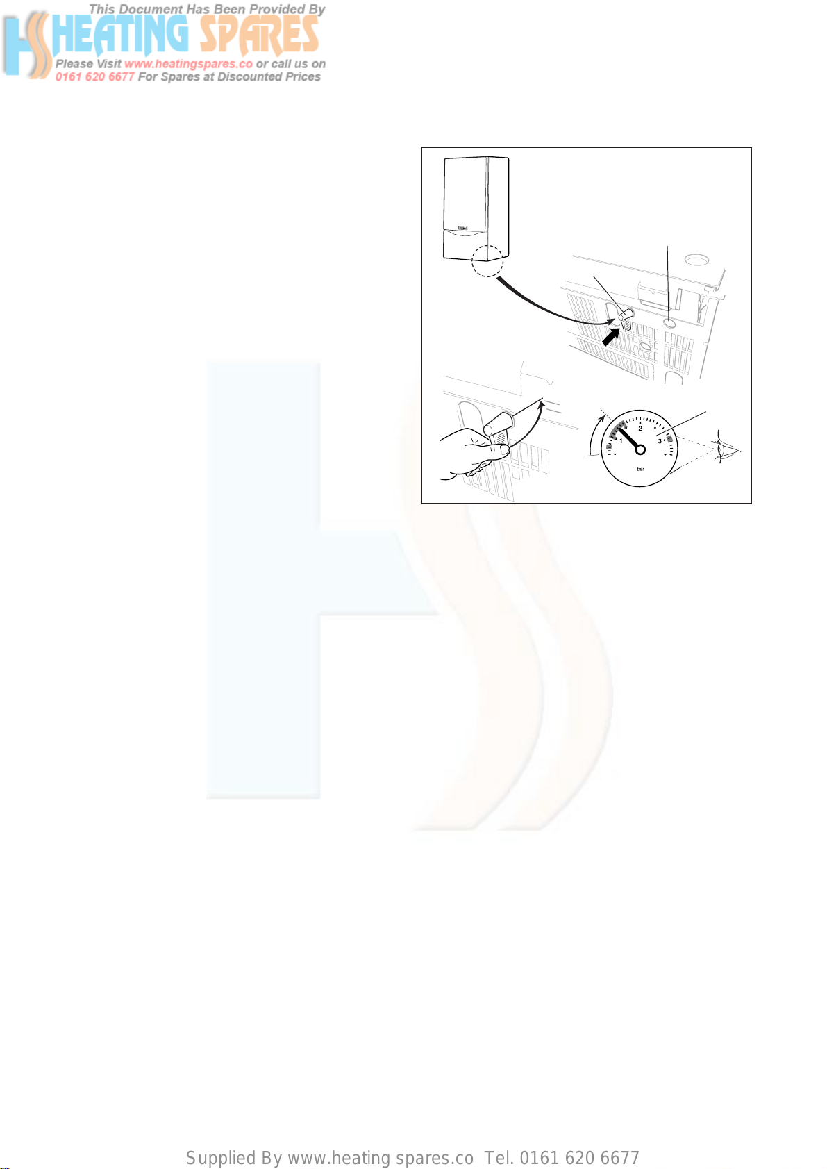
6.4 Filling the heating system (turboMAX plus)
Proceed as follows to fill the system:
• Open all radiator valves on the system.
• Check flexible filling loop is connected.
•Locate the filling valve handle on the cold water inlet
filling valve as shown (1).
• Open valve (1) fully.
•Remove filling valve handle and locate on return filling
valve (2).
• Open the valve slowly and fill the unit with water until
the required pressure has been acheived (3).
•Turn off valve (2).
•Remove valve handle and refit on cold water inlet
filling valve (1).
•Fully close valve (1).
•Bleed the air from the radiators.
•The boiler is equipped with an automatic air release
valve. To allow this to vent the boiler, the cap top must
be slackened by 1 - 2 turns. (This cap must be left
slackened during operation to ensure any residual air
or system gases are released).
Fig. 6.1: Fit boiler casing
3
1
90°
2
Supplied By www.heating spares.co Tel. 0161 620 6677
6 Commissioning Part I Gas supply adjustments (Com. Part II) 7
Instructions for Installation and Servicing turboMAX plus and thermoCOMPACT R126
7 Gas supply adjustments
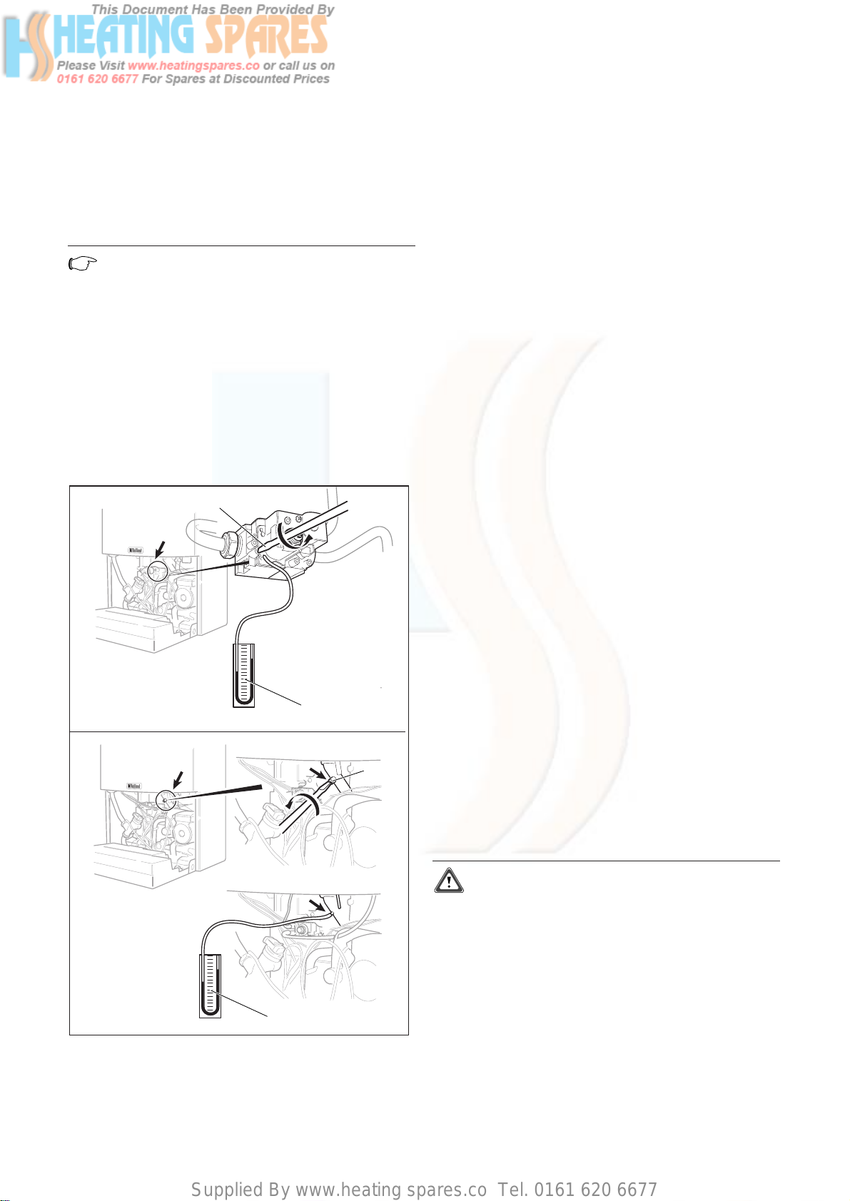
7.1 Gas inlet working pressure
To check the gas inlet working pressure:
•Lower the front panel of the boiler.
•Lower the control panel.
• Slacken the sealing screw (1) located at measuring
point ”P.IN”.
•Attach U-gauge to the inlet test point on the gas valve
(2).
• Ensure that the gas service valve is open.
•Turn off the boiler at the main ON/OFF control.
•Press and hold the ”+” button, while pressing the
button turn the main ON/OFF control to the ”1” ON
position.
•Continue holding ”+” button until display alternates
between ”P1” and ”P2”. Release ”+” button.
•Press ”+” button until ”P1” (full gas rate) is shown in
display.
•Press ”i” button to operate boiler at full gas rate.
• Check that the U-gauge is reading in the range
between 18 and 20 mbar. If the pressure is not within
this range this should be investigated before
continuing with the commissioning procedure. Lower
pressures than this range are indicative of an
incorrectly sized or partially blocked gas supply.
•Switch off the boiler at the main ON/OFF control.
•Remove U-gauge, tighten test point sealing screw (1).
•Test for soundness.
•Record appliance working gas inlet pressure (mbar) in
the Benchmark Installation, Commissioning and
Service Log Book.
Fig. 7.1: Gas inlet working pressure
1
1
2
6.5 Filling the heating system (thermoCOMPACT)
The boiler and the heating system should be filled using
a filling method as described on page 13.
• Ensure that the boiler CH service valves are open.
•Partially open the filling valve and allow water to
enter the system. Starting with the lowest radiator,
open the radiator air release until water (clear of
bubbles) is emitted.
•Repeat this at all radiators until the complete system
is full, all air locks have been cleared and the boiler
pressure gauge reads 1.5 bar. Release any air from the
pump by slackening the centre screw.
•The boiler is equipped with an automatic air release
valve. To allow this to vent the boiler, the cap on the
top must be slackened by 1 - 2 turns. (This cap must
be left slackened during boiler operation to ensure
any residual air or system gases are released).
• Check the heating system and boiler connections are
sound.
6.6 Initial system flush (“cold“)
The whole of the heating system must be flushed out at
least twice: once cold, and once hot as instructed later.
Open all radiator and heating valves and the boiler CH
service valves and drain the heating system and boiler
completely from the lowest points of the system via 1/2”
BSP drain taps (opened full bore to remove any
installation debris prior to lighting the boiler).
Refill the heating system.
Check the operation of the pressure relief valve by
rotating the knob on the valve.
Now check the water pressure in the unit again (and add
more water if necessary).
Supplied By www.heating spares.co Tel. 0161 620 6677
Gas supply adjustments (Commissioning Part II) 7
Instructions for Installation and Servicing turboMAX plus and thermoCOMPACT R1 27
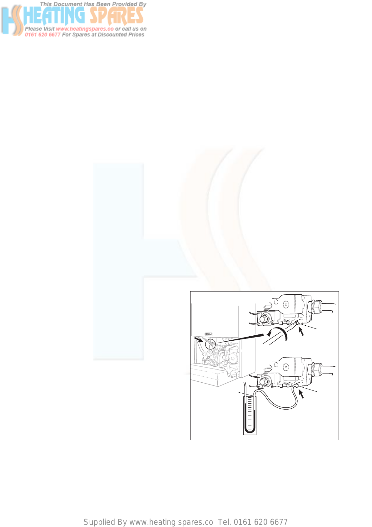
7.2 Main burner pressure
The burner pressure on this appliance has been factory
set and does not require adjustment. To check the main
burner pressure connect the U-Gauge as follows
depending on the gas type.
•Remove front case and combustion chamber cover.
Note!
All measurements and adjustments to the gas
valve must be done with the combustion
chamber cover removed.
For natural gas appliances:
• Slacken the sealing screw (1) at test point on the gas
valve and attach one arm of a U-gauge (2) to the test
point.
For LPG appliances:
• Slacken the sealing screw (1a) at test point on the
burner inlet gas pipe and attach one arm of a U-gauge
(2a) to the test point.
Fig. 7.2
1
1a
2
2a
Connection for Natural gas
Connection for LPG
•Turn off the boiler at the main ON/OFF control.
•Press and hold the ”+” button, while pressing the
button turn the main ON/OFF control to the ”1” ON
position.
•Continue holding ”+” button until display alternates
between ”P1” and ”P2”. Release ”+” button.
•Press ”+” button until ”P1” is shown in the display. ”P1”
indicates the maximum gas rate and ”P2” indicates
the ignition rate.
•Press ”i” button to operate boiler at maximum gas
rate.
Check that the burner pressure is correct as shown in
table 7.1 for the appropriate boiler. To cancel selected
”P1” or ”P2” mode press the ”i” and ”+” buttons
simultaneously.
turboMAX plus only
Measure the domestic hot water burner operating
pressure (mbar), the heat input (kW), the inlet/outlet
domestic hot water temperatures (°C) and flow rate
(l/min) by fully opening a hot water tap and record
details in the boiler logbook.
thermoCOMPACT only
Record the heat input in the boiler logbook.
After completion of all tests tighten sealing screw,
and check all test points for soundness (1/1a).
7. 3 Adjusting the central heating output
(range rating)
The boilers are fully modulating for central heating, and
it is therefore not necessary to range rate the boiler.
However, if desired, it is possible to range rate the boiler,
as follows:
•Connect the U-gauge to check burner pressure.
•Use Table 7.1 (page 31-32) on to determine the central
heating output required.
•Note the burner pressure setting.
•Turn on the central heating.
• Ensure that any thermostatic radiator valves are open
and set to high.
• Simultaneously press and release the ”+” and ”-”
buttons to activate burner pressure mode.
•The boiler will light at the factory set nominal gas rate.
Attention!
DO NOT open any hot water tap while carrying
out this procedure (turboMAX plus only).
• Check that the U-gauge reading corresponds to the
maximum burner pressure as detailed on the table.
• Identify required range rating setting and note main
burner pressure in mbar for that output.
•Adjust central heating output range as shown on page
29.
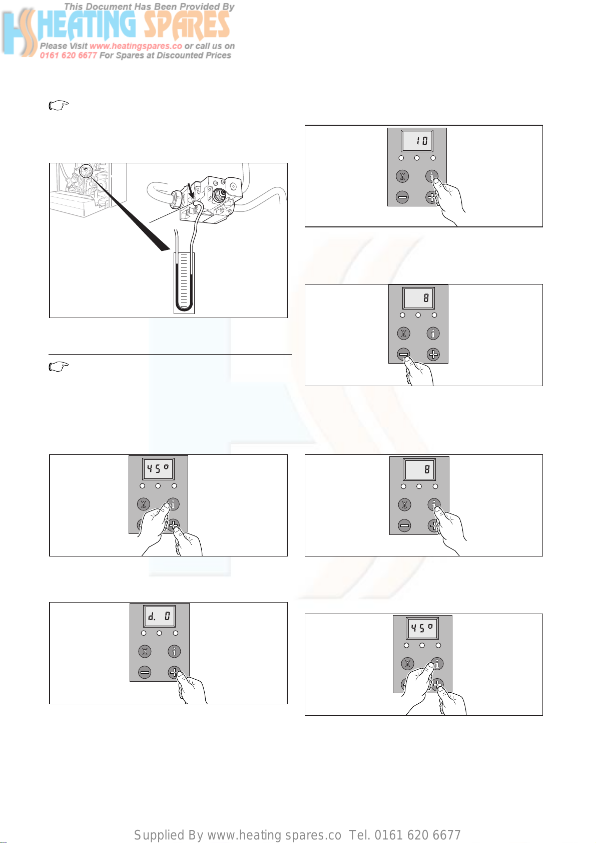
Supplied By www.heating spares.co Tel. 0161 620 6677
7 Gas supply adjustments (Commissioning Part II)
Note!
Following adjustment of the central heating
output, the new output can be checked using
the gas rate table as detailed.
Fig. 7.3: Using burner pressure to check and adjust the heating
system partial load (picture shows a turboMAX plus boiler)
Note!
This illustration shows the U-tube pressure
gauge connected to a system configured to run
on natural gas. When connecting the U-tube
pressure gauge to a system running on LPG,
please refer to Fig. 7.2 on page 27.
• Simultaneously press the ”i” and ”+” buttons keys.
•Keep the ”+” button pressed until ”d.0” is displayed.
(The display runs from ”d.0” to ”d.99” before
restarting again at ”d.0”.)
Instructions for Installation and Servicing turboMAX plus and thermoCOMPACT R128
•Press the ”i” button and a value between 1 and 15 will
be displayed.
•Use the ”+” or ”-” buttons to increase or decrease the
value. Observe the U-gauge as the button is pushed
and stop pushing when the required main burner
pressure has been achieved.
•After setting, press and hold the ”i” button for five
seconds - or until the display stops flashing. The new
setting value is now memorised. The new main burner
pressure can now be checked. If the new output is not
correct repeat steps 3 to 5.
•To return to normal mode, press the ”i” and ”+”
buttons simultaneously.
The adjustment mode is also cancelled if no button is
pushed for a period of four minutes.
•Record central heating operating pressure in the
Benchmark Log Book along with the heat input (kW)
and temperature difference between flow and return.
1
~ 5 s
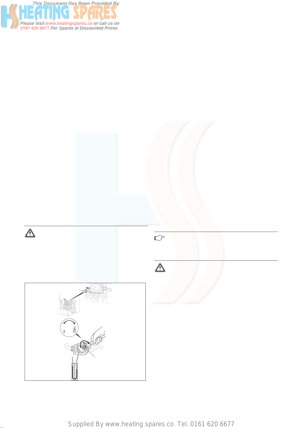
Supplied By www.heating spares.co Tel. 0161 620 6677
Gas supply adjustments (Commissioning Part II) 7
Instructions for Installation and Servicing turboMAX plus and thermoCOMPACT R1 29
7. 4 Adjusting to the maximum heat load
(nominal load)
• Undo screw and remove the cap (1)
turboMAX only:
•Set the DHW temperature control to maximum and
fire the boiler at full rate by fully opening a hot water
tap.
thermoCOMPACT only:
•Turn off the boiler at the main ON/OFF control.
•Press and hold the ”+” button, while pressing the
button turn the main ON/OFF control to the ”1” ON
position.
•Continue holding ”+” button until display alternates
between ”P1” and ”P2”. Release ”+” button.
•Press ”+” button until ”P1” (full gas rate) is shown in
display.
•Press ”i” button to operate boiler at full gas rate.
•Using a 10 mm spanner turn nut (2) to adjust the
burner operating pressure.
-Turn the nut (2) clockwise to increase the nominal
load
-Turn the nut (2) anticlockwise to decrease the nominal
load.
•Adjust the burner pressure until it matches the
maximum output as detailed.
•Now turn the 10 mm nut (2) anticlockwise until the
burner pressure drops by approx. 0.3 - 0.4 mbar.
Nominal load is now correctly adjusted.
•Refit the plastic cap (1).
Attention!
The plastic cap (2) must be fitted for the gas
valve assembly to function correctly.
turboMAX only:
•Turn off the hot water tap.
thermoCOMPACT only:
•To cancel selected ”P1“ or ”P2“ mode press the ”i“ and
”+“ buttons simultaneously.
Fig. 7.4: Adjusting the ignition rate
1
2
7.5 Adjusting the ignition rate
• Undo screw and remove the cap (1).
turcoMAX only:
• Disconnect the modulating coil wires from the gas
valve, set the DHW temperature control to maximum
and fire the boiler at full rate by fully opening a hot
water tap.
thermoCOMPACT only:
•Turn off the boiler at the main ON/OFF control.
•Press and hold the ”+” button, while pressing the
button turn the main ON/OFF control to the ”1” ON
position.
•Continue holding ”+” button until display alternates
between ”P1” and ”P2”. Release ”+” button.
•Press ”+” button until ”P2” (ignition rate) is shown in
display.
•Press ”i” button to operate boiler at full gas rate.
•Use a suitably sized screwdriver to turn the inner
screw (2).
•Turn the screw (2) clockwise to increase the ignation
rate
•Turn the screw (2) anticlockwise to decrease the
ignation rate
•Adjust the burner pressure until it matsches the
ignition rate as detailed on page 31 or 32.
turboMAX only:
•Turn off the hot water tap and reconnect the wires to
the modulating regulator.
thermoCOMPACT only:
•To cancel selected “P1“ or “P2“ mode press the “i“ and
“+“ buttons simultaneously.
Note!
If installing/commissioning a turboMAX plus
837 or a thermoCOMPACT 637 boiler go to page
30.
Attention!
The main burner pressure must be rechecked
after adjusting the ignition rate.
Refit cap (1) and replace screw. Re-check ignition and
main burner pressures. After completion of these tests
tighten the sealing screw and check all joints and test
points for soundness.
Supplied By www.heating spares.co Tel. 0161 620 6677
7 Gas supply adjustments (Commissioning Part II)
Instructions for Installation and Servicing turboMAX plus and thermoCOMPACT R130
7.6 Checking the gas valve mid setting point
(turboMAX plus 837 and thermoCOMPACT 637
only)
To ensure the most efficient operation of the boiler a
gas valve mid setting point is necessary.
This mid setting point has been factory set and
adjustment of this point is only required after
exchanging either the electronic circuit board or gas
valve or converting the boiler to another gas type.
To check the mid setting point proceed as follows.
•Turn off the boiler at the main ON/OFF control.
•Press and hold the ”+” button, while pressing the
button turn the main ON/OFF control to the ”I” ON
position.
•Continue holding ”+” button until display starts to
alternate between the P numbers (P1, P2, P3, P11, P12
and P13).
Release ”+” button.
•Press ”+” button until ”P3 ” (mid setting point) is
shown in display.
•Press ”i ” button to operate boiler at mid setting
point.
•The burner pressure should now read the mid setting
point pressure for the gas type used, as detailed in
the table below.
7.7 Setting or adjusting the mid-setting point
Turn off the boiler at the main ON/OFF control.
•Press and hold the ”+” button, while pressing the
button turn the main ON/OFF control to the ”I” ON
position.
•Continue holding ”+” button until display starts to
alternate between the P numbers (P1, P2, P3, P11, P12
and P13).
Release ”+” button.
•Press ”+” button until ”P11” (for natural gas) or "P 13"
(for LPG) is shown in display.
•Press ”i ” button to operate boiler at mid setting
point.
•The mid setting point burner pressure is now adjusted
by pushing the "+" button until the gauge equals the
pressure as detailed in the table below.
Note!
The "-" button has no function in this mode, if
the required pressure is exceeded during set up,
this operation should be recommenced from the
beginning.
When the pressure is correct, to save the setting to
memory, press and hold the "i" button until the display
stops flashing.
To cancel selected mode press the "i" and "+" buttons
simultaneously.
Refit cap and replace screw. Re-check ignition and main
burner pressures. After completion of these tests
tighten the sealing screw and check all joints and test
points for soundness.
Gas type Mid setting point presure
Natural Gas (G20) 5.3 mbar
LPG (G30/31) 15.3 mbar
Program No. Gas type Mid setting point
P.1 1 Natural Gas (G20) 5.3 mbar
P.12 Not applicable for GB -
P.13 LPG (G30/31) 15.3 mbar
 Loading...