

Page 1
Installation instructions
en, cs, da, de, es, fr, hr, hu, it, ko, pl,
305827
pt, ro, ru, sk, sl, sr, sv, tr, uk, zh
Publisher/manufacturer
Vaillant GmbH
Berghauser Str. 40
Tel. +49 21 91 18-0
info@vaillant.de www.vaillant.de
D-42859 Remscheid
Fax +49 21 91 18-2810
Page 2

en Installation instructions .........................................1
cn 安装说明 ....................................................................9
cs Návod k instalaci................................................... 15
da Installationsvejledning ........................................ 23
de Installationsanleitung ........................................... 31
es Instrucciones de instalación............................... 39
fr Notice d’installation ............................................ 47
hr Upute za instaliranje ........................................... 55
hu Szerelési útmutató .............................................. 63
it Istruzioni per l'installazione ................................ 71
ko 설치 설명서 .............................................................. 79
pl Instrukcja instalacji ............................................. 87
pt Manual de instalação ........................................... 95
ro Instrucţiuni de instalare ....................................103
ru Руководство по монтажу ................................... 111
sk Návod na inštaláciu .............................................119
sl Navodila za namestitev ...................................... 127
sr Uputstvo za instalaciju ...................................... 135
sv Installationsanvisning ........................................143
tr Montaj kılavuzu ....................................................151
uk Посібник зі встановлення ...............................159
en Country specifics and addresses ...................... 167
Page 3

Contents
Contents
1 Safety ........................................................................2
1.1 Action-related warnings ......................................... 2
1.2 Intended use ............................................................. 2
1.3 General safety information ................................... 3
2 Notes on the documentation ............................. 3
2.1 Observing other applicable documents ............. 3
2.2 Storing documents .................................................. 3
2.3 Validity of the instructions .................................... 3
3 Product description ..............................................4
3.1 Design of the product .............................................4
3.2 CE label ......................................................................4
3.3 Checking the scope of delivery ............................ 4
4 Installation ............................................................... 4
4.1 Selecting the installation location ....................... 4
4.2 Installing the safety assembly .............................. 5
5 Start-up ....................................................................6
5.1 Heating the cylinder ............................................... 6
5.2 No domestic hot water expansion vessel
installed ......................................................................6
6 Care and maintenance .........................................6
6.1 Caring for the product .......................................... 6
6.2 Checking that the safety assembly is working
correctly .....................................................................6
6.3 Cleaning the expansion relief valve .................... 7
6.4 Procuring spare parts.............................................7
7 Recycling and disposal.........................................8
7.1 Disposing of the packaging ................................... 8
8 Customer service ...................................................8
9 Technical data - General......................................8
1Installation instructions 0020230764_00
Page 4
Safety1a a
1 Safety
1.1 Action-related warnings
Classification of action-related warnings
The action-related warnings are classified in accordance with the severity of the possible danger using
the following warning signs and signal words:
Warning symbols and signal words
Danger!
a
Imminent danger to life or risk of severe
personal injury
Danger!
e
Risk of death from electric shock
Warning.
a
Risk of minor personal injury
Caution.
b
Risk of material or environmental damage
1.2 Intended use
There is a risk of injury or death to the user or others, or of damage to the product and other property
in the event of improper use or use for which it is
not intended.
The safety assembly is used as a safety device with
closed domestic hot water cylinders with a nominal
capacity of up to 1000 l.
It contains all of the fittings that are required to
equip closed domestic hot water cylinders up to
1000 l in accordance with DIN 1988.
The enclosed isolation valves must not be used to
restrict the flow rate, because this is not intended
use.
Intended use includes the following:
- observance of accompanying operating, installa-
tion and servicing instructions for the product
and any other system components
- installing and fitting the product in accordance
with the product and system approval
- compliance with all inspection and maintenance
conditions listed in the instructions.
Any other use that is not specified in these instructions, or use beyond that specified in this document
shall be considered improper use. Any direct commercial or industrial use is also deemed to be
improper.
Caution.
Improper use of any kind is prohibited.
2 Installation instructions 0020230764_00
Page 5
Notes on the documentationen2a a
1.3 General safety information
1.3.1 Risk caused by inadequate
qualifications
Applicability: Not for Russia
The following work must only be carried out by competent persons who are sufficiently qualified to do
so:
Applicability: Russia
The following work must only be carried out by
Vaillant-certified competent persons who are sufficiently qualified to do so:
- Set-up
- Dismantling
- Installation
- Start-up
- Inspection and maintenance
- Repair
- Decommissioning
> Observe all instructions that are included with the
product.
> Proceed in accordance with the current technol-
ogy.
> Observe all applicable directives, standards, laws
and other regulations.
1.3.2 Risk of being burned or scalded by
hot components
> Only carry out work on these components once
they have cooled down.
1.3.3 Risk of material damage caused by
frost
> Do not install the product in rooms prone to frost.
1.3.4 Risk of material damage caused by
using an unsuitable tool
> Use the correct tool to tighten or loosen screw
connections.
1.3.5 Regulations (directives, laws,
standards)
> Observe the national regulations, standards,
guidelines and laws.
2 Notes on the documentation
2.1 Observing other applicable
documents
> You must observe all the operating and installa-
tion instructions included with the system components.
2.2 Storing documents
> Pass these instructions and all other applicable
documents on to the system operator.
2.3 Validity of the instructions
These instructions apply only to:
- Safety group: 305827
3Installation instructions 0020230764_00
Page 6
Product description
3
3 Product description
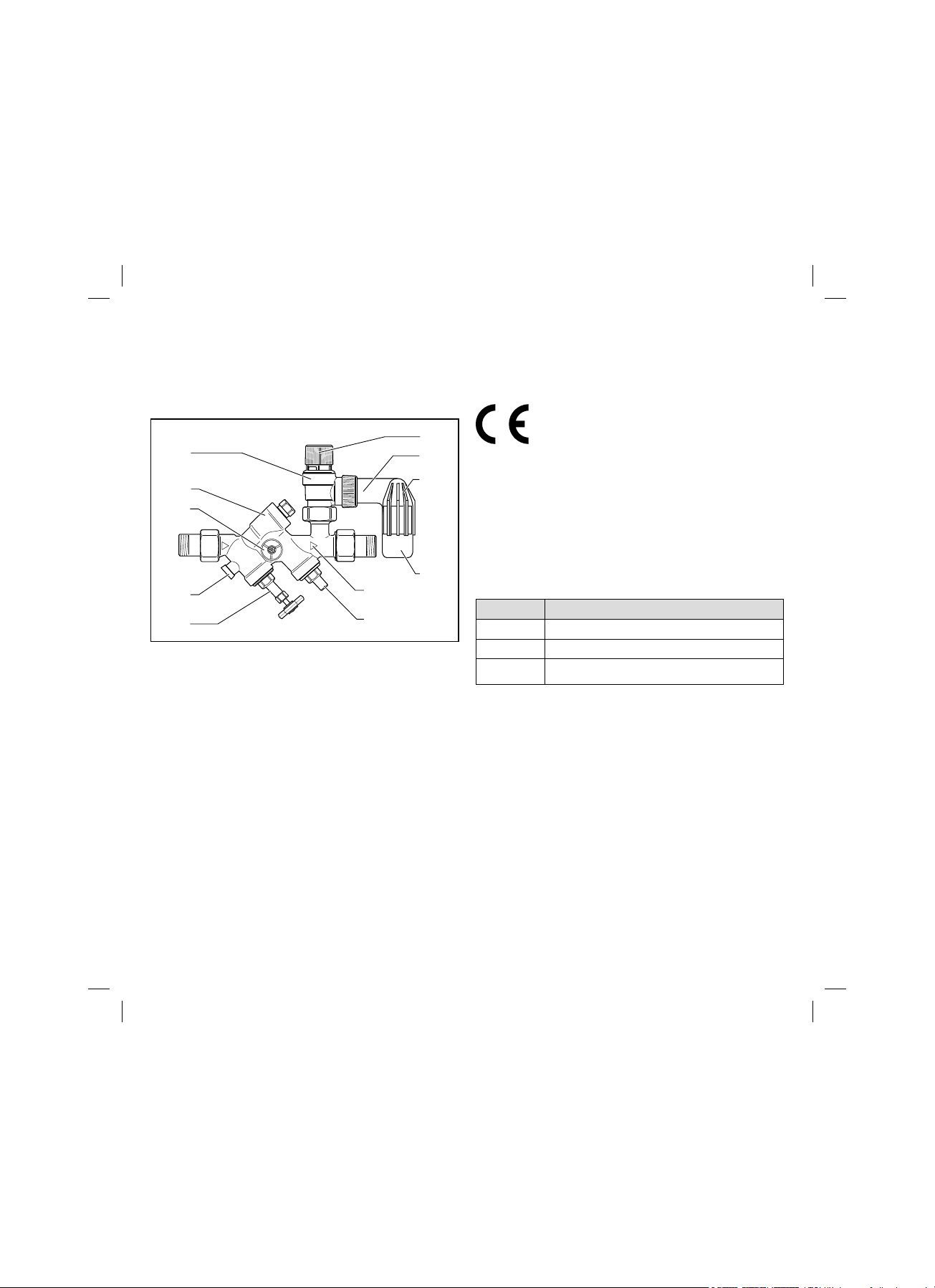
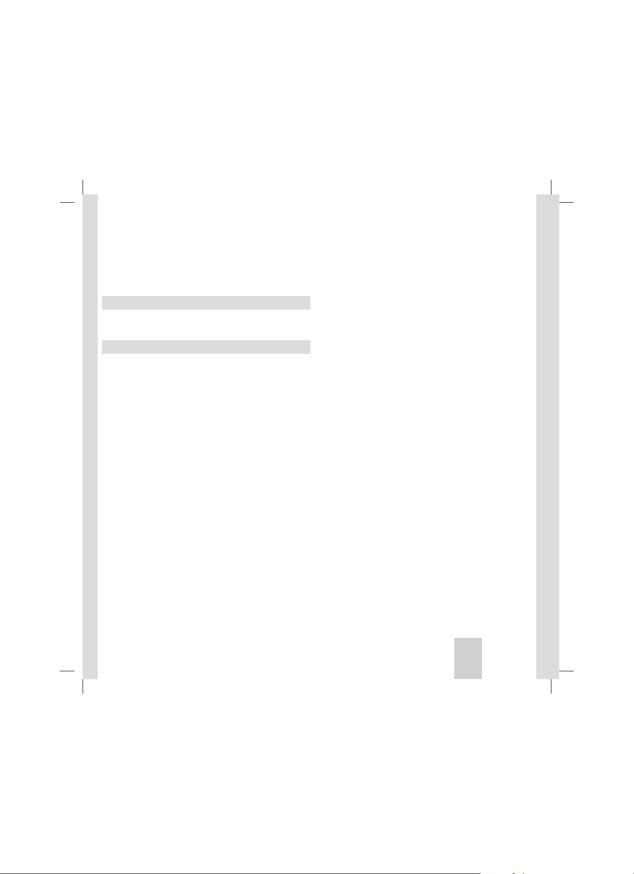
3.1 Design of the product
1
11
10
9
8
7
1 Venting cap
2 Discharge line
3 Hopper
4 Hopper drain
5 Flow direction
6 Stopvalve
7 Isolation valve with handwheel
8 Testplug
9 Pressure gauge connectors
10 Return flow prevention
11 Expansion relief valve
5
6
The isolation valves (6) and (7) interrupt the cold
water supply to the domestic hot water cylinder.
2
3
4
3.2 CE label
The CE label shows that the products comply with
the basic requirements of the applicable directives
as stated on the identification plate.
The declaration of conformity can be viewed at the
manufacturer's site.
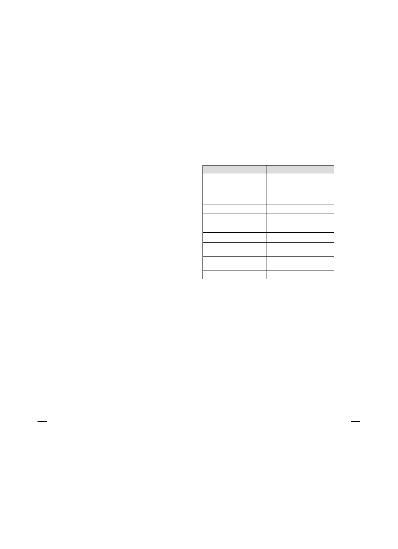
3.3 Checking the scope of delivery
> Check that the scope of delivery is complete and
intact.
Number Description
1 Safety group
1 Hopper
2 Screwed connections with seals
4 Installation
4.1 Selecting the installation location
Install the safety assembly above the domestic hot
water cylinder so that the domestic hot water cylinder does not have to be drained when maintenance
work is carried out on the safety assembly.
4
Installation instructions 0020230764_00
Page 7

Installationen4
Caution.
b
Adverse effect on how the safety
assembly functions.
> Do not install any shut-offs, constricted
sections or line strainers between the
safety assembly and the domestic hot
water cylinder.
> Install the safety assembly upstream of the
domestic hot water cylinder in the cold water supply pipe.
> Install the safety assembly so that it is easily
accessible in order to facilitate purging.
> Install the safety assembly as a corner or straight
shape in horizontal or vertical pipes (flow upwards
from below).
4.2 Installing the safety assembly
> Remove the residues from the cold water supply
line by rinsing or blowing through before connecting the safety assembly. Small particles of dirt
may prevent the valve from working correctly
and/or lead to permanent loss of water.
> During the installation, ensure that the arrow (5)
on the safety assembly is pointing in the flow
direction.
> Install the hopper (3) on the expansion relief
valve's (11) discharge pipe (2).
> Install a 1" drain pipework on the hopper drain
(4).
Danger!
a
Risk of scalding
> Install the safety assembly correctly to
ensure that no person is at risk from
hot water or hot steam that is discharged from the expansion relief
valve.
Caution.
b
Risk of material damage caused by
restricting the safety function. The
expansion relief valve must be blown
out against atmospheric pressure.
> Install the hopper drain (4) in such a
way that it remains open at all times.
> Make the end user aware of this.
5Installation instructions 0020230764_00
Page 8

Start-up
5
5 Start-up
5.1 Heating the cylinder
When heating the cylinder, the installed non-return
valve (10) prevents the heated water from flowing
back into the cold water supply line. The excess pressure in the cylinder, which is caused by the heating,
is reduced by opening the expansion relief valve (11).
Danger!
a
Risk of scalding
> When opening the expansion relief
valve by heating up the cylinder and by
actuating the venting cap (1), hot water
escapes at the hopper drain (4).
5.2 No domestic hot water expansion
vessel installed
If no domestic hot water expansion vessel is
installed, a water volume based on the water content
of the domestic hot water cylinder and the temperature boost must escape from the hopper drain (4)
on the expansion relief valve (11) when the domestic
hot water cylinder is heated.
6 Care and maintenance
6.1 Caring for the product
Caution.
b
Risk of material damage caused by
unsuitable cleaning agents.
> Do not use sprays, scouring agents,
detergents, solvents or cleaning agents
that contain chlorine.
> Clean the casing with a damp cloth and a little
solventfree soap.
6.2 Checking that the safety assembly is
working correctly
1. Check that the expansion relief valve (11) is work-
ing correctly twice a year and each time the
domestic hot water cylinder is started up.
2. Turn the venting cap (1) in the direction of the
arrow that is marked on the cap.
¬ Water must flow into the hopper (3) here.
¬ The expansion relief valve (11) must then be
leak-tight again.
Conditions: The expansion relief valve permanently drips
> Clean the expansion relief valve.
3. Check that the non-return valve (10) is working
correctly once a year.
4. Close the isolation valve (7).
5. Unscrew the check plug (8).
6
Installation instructions 0020230764_00
Page 9

¯ If water continuously escapes, the non-return
valve (10) is defective. In this case, replace the
safety assembly.
6. Each time the domestic hot water cylinder is
started up again, open the isolation valves (6)
and (7) fully.
7. Each time maintenance work is carried out on
the domestic hot water cylinder (at least every
two years), check that the safety assembly is
working correctly.
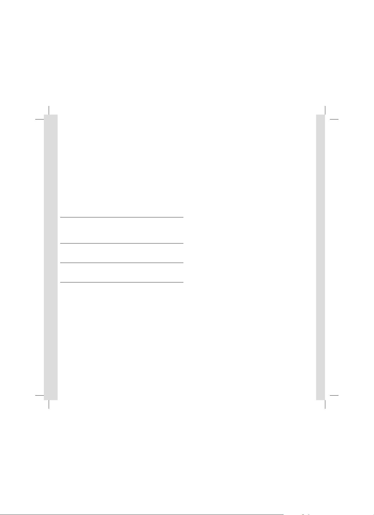
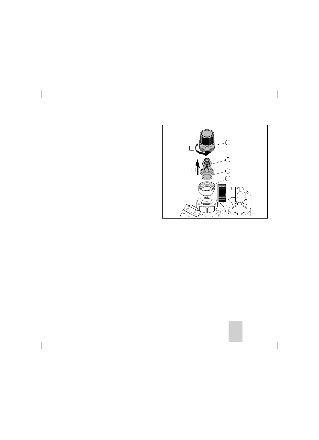
6.3 Cleaning the expansion relief valve
Note
i
The expansion relief valve can be cleaned
without changing the operating pressure.
Care and maintenanceen6
1
A
2
B
3
4
1. Use the handwheel (7) to close the isolation
valve.
2. Drain the domestic hot water cylinder.
3. Remove the upper section (1) of the expansion
relief valve.
4. Remove the valve insert (2).
5. Clean the seal (3) and the valve seat (4). Replace
any defective seals.
6. Reinstall the valve insert and upper section.
7. Open the isolation valve and check that the
expansion relief valve is leak-tight.
6.4 Procuring spare parts
The original components of the product were also
certified by the manufacturer as part of the declaration of conformity. If you use other, non-certified or
unauthorised parts during maintenance or repair
work, this may void the conformity of the product
and it will therefore no longer comply with the applicable standards.
7Installation instructions 0020230764_00
Page 10
Recycling and disposal
7
We strongly recommend that you use original spare
parts from the manufacturer as this guarantees
fault-free and safe operation of the product. To
receive information about the available original
spare parts, contact the contact address provided on
the reverse of these instructions.
> If you require spare parts for maintenance or
repair work, use only the spare parts that are permitted for the product.
7 Recycling and disposal
7.1 Disposing of the packaging
> Dispose of the packaging correctly.
> Observe all relevant regulations.
8 Customer service
The contact details for our customer service are provided on our website.
9 Technical data - General
10 bar safety assembly
Art. no. 305827
Operating pressure 10 bar
Nominal size DN 20
Screwed connection R 3/4"
For cylinder water heaters
with max. nominal capacity
Max. heating output 150 kW
Expansion relief valve
component mark
Safety assembly sound
insulation test symbol
DVGW test number NW-6311AP2713
1000 l
TÜV-SV03-545-1/2"-W10
PA-IX 1794/1
8
Installation instructions 0020230764_00
Page 11

Obsah
Obsah
1 Bezpečnost .............................................................10
1.1 Výstražná upozornění související s
manipulací ................................................................10
1.2 Použití v souladu s určením .................................10
1.3 Všeobecné bezpečnostní pokyny.........................11
2 Pokyny k dokumentaci .........................................11
2.1 Dodržování platné dokumentace .........................11
2.2 Uložení dokumentace .............................................11
2.3 Platnost návodu .......................................................11
3 Popis výrobku ........................................................12
3.1 Konstrukce výrobku ...............................................12
3.2 Označení CE .............................................................12
3.3 Kontrola rozsahu dodávky ....................................12
4 Montáž ......................................................................12
4.1 Výběr místa montáže ............................................ 12
4.2 Instalace pojistné skupiny ....................................13
5 Uvedení do provozu ..............................................14
5.1 Zahřátí zásobníku ...................................................14
5.2 Není instalována žádná expanzní nádoba
systému k ohřevu teplé vody ...............................14
6 Péče a údržba ........................................................14
6.1 Péče o výrobek........................................................14
6.2 Kontrola funkce pojistné skupiny .......................14
6.3 Čištění pojistného ventilu ..................................... 15
6.4 Nákup náhradních dílů ..........................................15
7 Recyklace a likvidace ..........................................16
7.1 Likvidace obalu .....................................................16
8 Servis ........................................................................16
9 Technické údaje všeobecně ............................... 16
9Návod k instalaci 0020230764_00
Page 12

Bezpečnost1a a
1 Bezpečnost
1.1 Výstražná upozornění související s
manipulací
Klasifikace výstražných upozornění souvisejících
s manipulací
Výstražná upozornění související s manipulací jsou
pomocí výstražných značek a signálních slov odstupňována podle závažnosti možného nebezpečí:
Výstražné značky a signální slova
Nebezpečí!
a
Bezprostřední ohrožení života nebo
nebezpečí závažného zranění osob
Nebezpečí!
e
Nebezpečí úrazu elektrickým proudem
Varování!
a
Nebezpečí lehkých zranění osob
Pozor!
b
Riziko věcných nebo ekologických škod
1.2 Použití v souladu s určením
Při neodborném používání nebo použití v rozporu s
určením může dojít k ohrožení zdraví a života uživatele nebo třetích osob, resp. k poškození výrobku a k
jiným věcným škodám.
Pojistná skupina se používá jako bezpečnostní zařízení u uzavřených zásobníků teplé vody do jmenovitého objemu 1 000 l.
Obsahuje všechny armatury potřebné k vybavení
uzavřeného zásobníku teplé vody do 1 000 l podle
DIN 1988.
Příslušné uzavírací ventily se nesmějí používat k
omezování průtoku, protože by se jednalo o použití v
rozporu s určením.
Použití v souladu s určením zahrnuje:
- dodržování přiložených návodů k obsluze, insta-
laci a údržbě výrobku a všech dalších součástí
systému
- instalaci a montáž v souladu se schválením
výrobků a systému
- dodržování všech podmínek prohlídek a údržby
uvedených v návodech.
Jiné použití, než je popsáno v tomto návodu, nebo
použití, které přesahuje zde popsaný účel, je považováno za použití v rozporu s určením. Každé přímé
komerční nebo průmyslové použití je také v rozporu
s určením.
Pozor!
Jakékoliv zneužití či nedovolené použití je zakázáno.
10 Návod k instalaci 0020230764_00
Page 13
Pokyny k dokumentacics2a a
1.3 Všeobecné bezpečnostní pokyny
1.3.1 Nebezpečí při nedostatečné
kvalifikaci
Platnost: Nikoli pro Rusko
Následující práce smějí provádět pouze instalatéři,
kteří mají dostatečnou kvalifikaci:
Platnost: Rusko
Následující práce smějí provádět pouze instalatéři s
certifikací Vaillant, kteří mají dostatečnou kvalifikaci:
- Montáž
- Demontáž
- Instalace
- Uvedení do provozu
- Inspekce a údržba
- Oprava
- Odstavení z provozu
> Dodržujte všechny návody dodané s výrobkem.
> Postupujte podle aktuálního stavu techniky.
> Dodržujte všechny příslušné směrnice, normy,
zákony a jiné předpisy.
1.3.2 Nebezpečí popálení a opaření horkými
součástmi
> Na součástech pracujte, až vychladnou.
1.3.4 Riziko věcných škod v důsledku
použití nevhodného nářadí
> Při dotahování nebo povolování šroubových spojů
používejte správné nářadí.
1.3.5 Předpisy (směrnice, zákony, vyhlášky
a normy)
> Dodržujte vnitrostátní předpisy, normy, směrnice
a zákony.
2 Pokyny k dokumentaci
2.1 Dodržování platné dokumentace
> Bezpodmínečně dodržujte všechny návody k
obsluze a instalaci, které jsou připojeny ke komponentám zařízení.
2.2 Uložení dokumentace
> Tento návod a veškerou platnou dokumentaci pře-
dejte provozovateli zařízení.
2.3 Platnost návodu
Tento návod k obsluze platí výhradně pro:
- Pojistná skupina: 305827
1.3.3 Riziko věcných škod v důsledku
mrazu
> Neinstalujte výrobek v prostorech ohrožených
mrazem.
11Návod k instalaci 0020230764_00
Page 14

Popis výrobku
3
3 Popis výrobku
3.1 Konstrukce výrobku
11
10
9
8
7
1 Odvzdušňovací rukojeť
2 Odfukovací potrubí
3 Trychtýř
4 Odtok trychtýře
5 Směrprůtoku
6 Uzavírací ventil
7 Uzavírací ventil s ručním kolečkem
8 Zkušební hrdlo
9 Hrdlo připojení manometru
10 Zamezovač zpětného toku
11 Pojistný ventil
3.2 Označení CE
1
2
3
Označením CE se dokládá, že výrobky podle typového štítku splňují základní požadavky příslušných
směrnic.
Prohlášení o shodě je k nahlédnutí u výrobce.
3.3 Kontrola rozsahu dodávky
> Zkontrolujte úplnost a neporušenost dodávky.
4
5
6
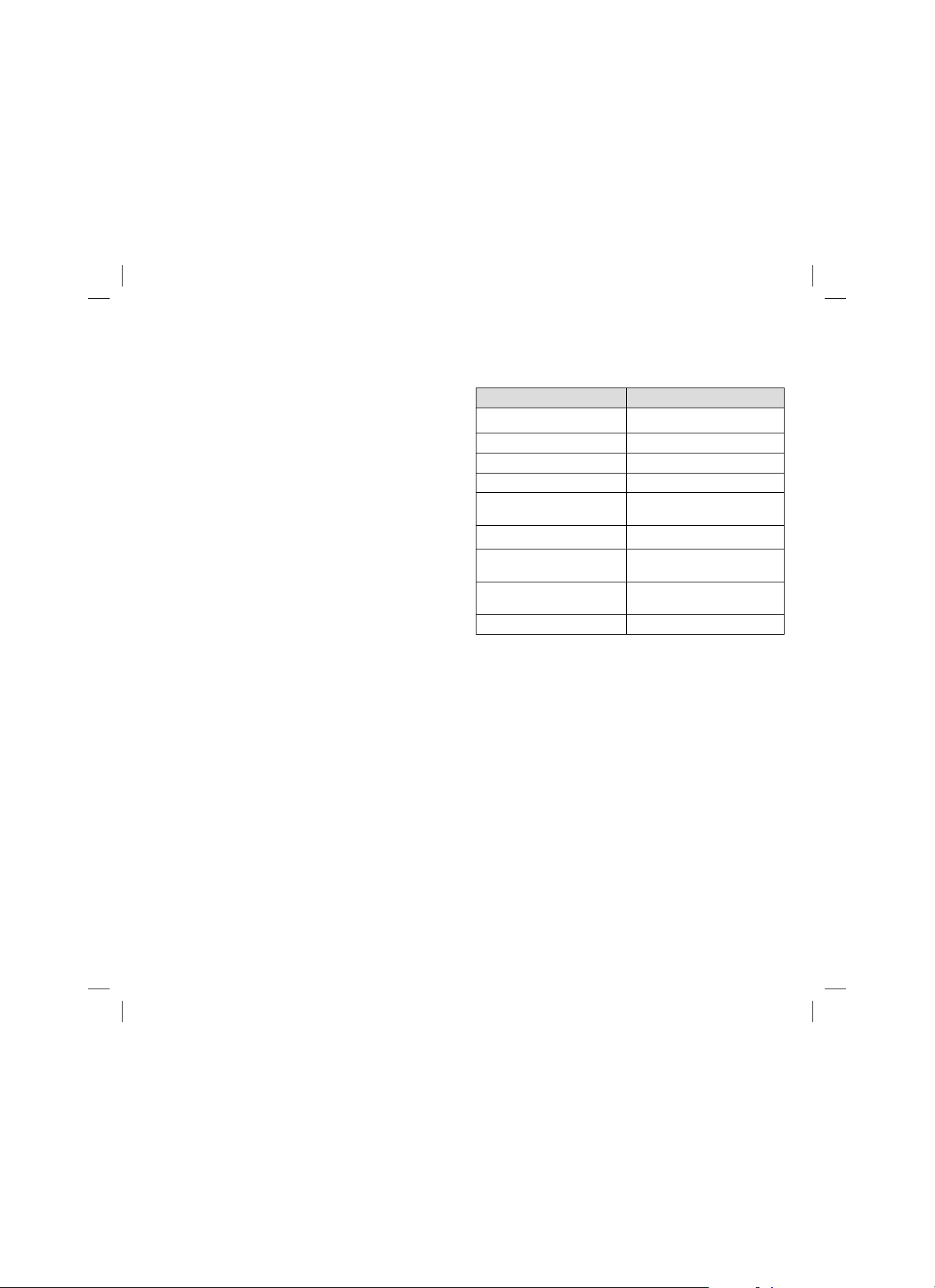
Množství Označení
1 Pojistná skupina
1 Trychtýř
2 Šroubení s těsněními
4 Montáž
4.1 Výběr místa montáže
Namontujte pojistnou skupinu nad zásobníkem teplé
vody, aby se při údržbě pojistné skupiny nemusel
vypouštět zásobník teplé vody.
Uzavírací ventily (6) a (7) přerušují přívod studené
vody k zásobníku teplé vody.
12
Návod k instalaci 0020230764_00
Page 15

Montážcs4
Pozor!
b
Omezení funkčnosti pojistné skupiny!
> Mezi pojistnou skupinu a zásobník teplé
vody nemontujte žádné uzávěry, zúžení
nebo filtry.
> Namontujte pojistnou skupinu před zásobníkem
teplé vody v potrubí na studenou vodu.
> Namontujte pojistnou skupinu tak, aby byla dobře
přístupná pro jednoduché odvzdušnění.
> Namontujte pojistnou skupinu v rohovém nebo
průchozím provedení do vodorovných nebo svislých vedení (proudění zdola nahoru).
4.2 Instalace pojistné skupiny
> Před připojením pojistné skupiny propláchnutím
nebo profouknutím odstraňte zbytky z potrubí na
studenou vodu. Částečky nečistot mohou ovlivnit
funkci ventilu a/nebo způsobit trvalou ztrátu vody.
> Při instalaci dbejte na to, aby šipka (5) na pojistné
skupině ukazovala ve směru proudění.
> Namontujte trychtýř (3) na odfukovací potrubí
(2) pojistného ventilu (11).
> Na odtok trychtýře (4) namontujte odtokové
potrubí o průměru 1".
Nebezpečí!
a
Nebezpečí opaření
> Vhodnou montáží pojistné skupiny
zajistěte, aby při odfukování z pojistného ventilu nebyly horkou vodou nebo
horkou párou ohroženy žádné osoby.
Pozor!
b
Nebezpečí věcných škod v důsledku
omezení bezpečnostní funkce! Odfukování pojistného ventilu musí být možné
proti atmosférickému tlaku.
> Odtok trychtýře (4) namontujte tak,
aby byl vždy otevřený.
> Upozorněte na to provozovatele.
13Návod k instalaci 0020230764_00
Page 16

Uvedení do provozu
5
5 Uvedení do provozu
5.1 Zahřátí zásobníku
Při zahřátí zásobníku zabraňuje namontovaný zamezovač zpětného toku (10) zpětnému proudění
zahřáté vody do potrubí na studenou vodu. Přetlak v
zásobníku vzniklý zahřátím se snižuje otevřením
pojistného ventilu (11).
Nebezpečí!
a
Nebezpečí opaření
> Při otevření pojistného ventilu při
zahřátí zásobníku a aktivaci odvzdušňovací rukojeti (1) vystupuje z odtoku
trychtýře (4) horká voda.
5.2 Není instalována žádná expanzní
nádoba systému k ohřevu teplé vody
Není-li instalována žádná expanzní nádoba systému
k ohřevu teplé vody, musí při zahřátí zásobníku teplé
vody vytékat z odtoku trychtýře (4) pojistného ven-
tilu (11) množství vody závislé na objemu zásobníku
teplé vody a zvýšení teploty.
6 Péče a údržba
6.1 Péče o výrobek
Pozor!
b
Riziko věcných škod v důsledku
nevhodných čisticích prostředků!
> Nepoužívejte spreje, abraziva, mycí
prostředky, čisticí prostředky s obsahem rozpouštědel nebo chlóru.
> Plášť čistěte vlhkým hadříkem namočeným ve sla-
bém roztoku mýdla bez obsahu rozpouštědel.
6.2 Kontrola funkce pojistné skupiny
1. Každého půl roku a při každém uvedení zásobníku teplé vody do provozu zkontrolujte funkčnost pojistného ventilu (11).
2. Odvzdušňovací rukojeť (1) otočte ve směru šipky
vyznačené na rukojeti.
¬ Přitom musí téct voda do trychtýře (3).
¬ Potom pojistný ventil (11) opět těsně uzavřete.
Podmínky: Pojistný ventil trvale kape
14
> Vyčistěte pojistný ventil.
3. Každý rok zkontrolujte funkčnost zamezovače
zpětného toku (10).
4. Zavřete uzavírací ventil (7).
5. Vyšroubujte zkušební hrdlo (8).
Návod k instalaci 0020230764_00
Page 17

¯ Při trvalém úniku vody je zamezovač zpětného
toku (10) vadný. V tomto případě pojistnou skupinu vyměňte.
6. Při každém opakovaném uvedení zásobníku teplé
vody do provozu zcela otevřete uzavírací ventily
(6) a (7).
7. Při každé údržbě zásobníku teplé vody (minimálně každé 2 roky) zkontrolujte funkčnost
pojistné skupiny.
6.3 Čištění pojistného ventilu
Pokyn
i
Pojistný ventil lze čistit beze změny aktivačního tlaku.
1. Zavřete uzavírací ventil ručním kolečkem (7).
2. Vypusťte zásobník teplé vody.
Péče a údržbacs6
1
A
2
B
3. Demontujte horní část (1) pojistného ventilu.
4. Odstraňte ventilovou vložku (2).
5. Vyčistěte těsnění (3) a sedlo ventilu (4).
Vyměňte vadná těsnění.
6. Znovu namontujte ventilovou vložku a horní část.
7. Otevřete uzavírací ventil a zkontrolujte těsnost
pojistného ventilu.
3
4
6.4 Nákup náhradních dílů
Originální díly výrobku byly certifikovány výrobcem v
souladu s ověřením shody. Používáte-li při údržbě
nebo opravě jiné, necertifikované, resp. neschválené
díly, může dojít k zániku souladu výrobku, který tak
již neodpovídá platným normám.
Důrazně doporučujeme, abyste používali originální
náhradní díly výrobce, protože je tím zaručen bezporuchový a bezpečný provoz výrobku. Informace o
15Návod k instalaci 0020230764_00
Page 18
Recyklace a likvidace
7
dostupných originálních náhradních dílech získáte na
kontaktní adrese, která je uvedena na zadní straně
příslušného návodu.
> Potřebujete-li při údržbě nebo opravě náhradní
díly, používejte výhradně ty, které jsou pro výrobek schváleny.
7 Recyklace a likvidace
7.1 Likvidace obalu
> Obal odborně zlikvidujte.
> Dodržujte všechny příslušné předpisy.
8 Servis
Kontaktní údaje na naši zákaznickou službu najdete
na našich webových stránkách.
9 Technické údaje všeobecně
Pojistná skupina 10 bar
Obj. č. 305827
Aktivační tlak 10 bar
Jmenovitá velikost DN 20
Připojovací šroubení R 3/4"
Pro zásobník teplé vody s
jmenovitým objemem max.
Ohřívací výkon max. 150 kW
Značka součásti pojistného ventilu
Ochranná známka zvukové
izolace pojistné skupiny
Zkušební číslo DVGW NW-6311AP2713
1000 l
TÜV-SV03-545-1/2"-W10
PA-IX 1794/1
16
Návod k instalaci 0020230764_00
Page 19

Indhold
Indhold
1 Sikkerhed .................................................................18
1.1 Handlingsrelaterede advarsler ............................18
1.2 Korrekt anvendelse ................................................18
1.3 Generelle sikkerhedsanvisninger ........................19
2 Henvisninger vedrørende dokumentationen 19
2.1 Overholdelse af øvrig dokumentation ...............19
2.2 Opbevaring af dokumentation.............................19
2.3 Vejledningens gyldighed .......................................19
3 Produktbeskrivelse .............................................20
3.1 Produktets opbygning ..........................................20
3.2 CE-mærkning ..........................................................20
3.3 Kontrol af leveringsomfanget .............................20
4 Montering ...............................................................20
4.1 Valg af opstillingssted ..........................................20
4.2 Installation af sikkerhedsgruppen ......................21
5 Idrifttagning...........................................................22
5.1 Opvarmning af beholderen .................................22
5.2 Ingen varmtvands-ekspansionsbeholder
installeret .................................................................22
6 Rengøring og vedligeholdelse .......................... 22
6.1 Vedligeholdelse af produktet ............................22
6.2 Kontrol af sikkerhedsgruppens funktion ......... 22
6.3 Rengøring af sikkerhedsventilen ....................... 23
6.4 Fremskaffelse af reservedele..............................23
7 Genbrug og bortskaffelse .................................. 24
7.1 Bortskaffelse af emballagen ............................... 24
8 Kundeservice .........................................................24
9 Tekniske data generelt .......................................24
17Installationsvejledning 0020230764_00
Page 20
Sikkerhed1a a
1 Sikkerhed
1.1 Handlingsrelaterede advarsler
Klassificering af handlingsrelaterede advarsler
De handlingsrelaterede advarsler er forsynet med
advarselssymboler og signalord, der passer til farens
mulige omfang.
Advarselssymboler og signalord
Fare!
a
Umiddelbar livsfare eller fare for alvorlige
kvæstelser
Fare!
e
Livsfare på grund af elektrisk stød
Advarsel!
a
Fare for lette kvæstelser
Forsigtig!
b
Risiko for materielle skader eller miljøskader
1.2 Korrekt anvendelse
Alligevel kan brugeren eller tredjemand udsættes for
fare, evt. med døden til følge, og produktet samt
andre ting kan blive beskadiget som følge af enhver
form for forkert brug.
Sikkerhedsgruppen anvendes som sikkerhedsanordning ved lukkede varmtvandsbeholdere med et nominelt indhold på indtil 1000 l.
Den indeholder alle armaturer, som kræves til
udrustning af lukkede varmtvandsbeholdere indtil
1000 l iht. DIN 1988.
De indeholdte stopventiler må ikke benyttes til drosling af gennemstrømningen, da dette ikke er anvendelse i overensstemmelse med formålet.
Korrekt anvendelse omfatter:
- overholdelse af de medfølgende betjenings-,
installations- og vedligeholdelsesvejledninger til
produktet samt alle øvrige anlægskomponenter
- installation og montering i overensstemmelse
med apparatets og systemets godkendelse
- overholdelse af alle de eftersyns- og servicebetin-
gelser, der fremgår af vejledningerne.
Anden anvendelse end den, der er beskrevet i denne
vejledning, og anvendelse, der går ud over den her
beskrevne, er forkert. Forkert anvendelse omfatter
også enhver umiddelbar kommerciel og industriel
anvendelse.
Bemærk!
Enhver ikke-godkendt anvendelse er forbudt.
18 Installationsvejledning 0020230764_00
Page 21

Henvisninger vedrørende dokumentationenda2a a
1.3 Generelle sikkerhedsanvisninger
1.3.1 Fare som følge af utilstrækkelig
kvalifikation
Gyldighed: Ikke for Rusland
Følgende arbejder må kun udføres af en VVS-installatør med tilstrækkelige kvalifikationer:
Gyldighed: Rusland
Følgende arbejder må kun udføres af Vaillant certificerede VVS-installatører med tilstrækkelige kvalifikationer:
- Montering
- Afmontering
- Installation
- Idrifttagning
- Eftersyn og service
- Reparation
- Standsning
> Følg alle de vejledninger, der fulgte med pro-
duktet.
> Gå frem i henhold til den højeste standard.
> Overhold alle gældende retningslinjer, normer,
love og andre forskrifter.
1.3.2 Fare for forbrænding eller skoldning
som følge af varme komponenter
> Der må først udføres arbejde på komponenterne,
når de er kølet af.
1.3.3 Risiko for materiel skade på grund af
frost
> Installer ikke produktet i rum med frostrisiko.
1.3.4 Risiko for materiel skade på grund af
uegnet værktøj
> Brug korrekt værktøj til at løsne eller spænde
skrueforbindelserne.
1.3.5 Forskrifter (direktiver, love,
standarder)
> Overhold de gældende forskrifter, standarder,
direktiver og love.
2 Henvisninger vedrørende
dokumentationen
2.1 Overholdelse af øvrig dokumentation
> Følg altid alle de drifts- og installationsvejlednin-
ger, der leveres med anlæggets komponenter.
2.2 Opbevaring af dokumentation
> Giv denne vejledning samt alle andre gældende
bilag videre til den systemansvarlige ejer.
2.3 Vejledningens gyldighed
Denne vejledning gælder udelukkende for:
- Sikkerhedsgruppe: 305827
19Installationsvejledning 0020230764_00
Page 22

Produktbeskrivelse
3
3 Produktbeskrivelse
3.1 Produktets opbygning
11
10
9
8
7
1 Ventilationsgreb
2 Afblæsningsrør
3 Tragt
4 Tragtafløb
5 Gennemløbsretning
6 Stopventil
7 Stopventil med håndtag
8 Kontrolprop
9 Manometer-tilslutningsstuds
10 Kontraventil
11 Sikkerhedsventil
3.2 CE-mærkning
1
2
3
CE-mærkningen dokumenterer, at produkterne i henhold til typeskiltet overholder de grundlæggende
krav i de relevante direktiver.
Overensstemmelseserklæringen foreligger hos producenten.
3.3 Kontrol af leveringsomfanget
4
5
6
> Kontrollér, at leveringsomfanget er komplet og
ikke har mangler.
Mængde Betegnelse
1 Sikkerhedsgruppe
1 Tragt
2 Forskruninger med pakninger
4 Montering
4.1 Valg af opstillingssted
Monter sikkerhedsgruppen over varmtvandsbeholderen, så varmtvandsbeholderen ikke skal tømmes ved
vedligeholdelsesarbejde på sikkerhedsgruppen.
Lukkeventil (6) og (7) afbryder tilførslen af koldt
vand til varmvandsbeholderen.
20
Installationsvejledning 0020230764_00
Page 23

Monteringda4
Forsigtig!
b
Risiko for begrænsning af sikkerhedsgruppens funktionsevne!
> Monter ikke nogen afspærringer,
forsnævringer eller smudsfangere mellem sikkerhedsgruppen og varmtvandsbeholderen.
> Installer sikkerhedsgruppen i koldtvandstilførsels-
ledningen før varmtvandsbeholderen.
> Monter sikkerhedsgruppen let tilgængeligt for at
lette udluftning.
> Installer sikkerhedsgruppen som hjørne- eller
gennemgangsform i vandrette eller lodrette ledninger (gennemstrømning nedefra og op).
4.2 Installation af sikkerhedsgruppen
> Fjern alle rester i koldtvandstilførselsledningen
ved at skylle eller blæse den igennem, inden sikkerhedsgruppen tilsluttes. Smudspartikler kan
hæmme ventilfunktionen og/eller føre til permanent vandtab.
> Sørg ved installationen for, at pilen (5) på sikker-
hedsgruppen peger i strømningsretningen.
> Monter tragten (3) på sikkerhedsventilens (11)
afblæsningsrør (2).
> Monter en 1 -afløbsledning på tragtafløbet (4).
Fare!
a
Fare for skoldning
> Sikr dig vha. en egnet montering af sik-
kerhedsgruppen, at personer ikke bringes i fare som følge af varmt vand eller
varm damp, som slipper ud af sikkerhedsventilen.
Forsigtig!
b
Risiko for materiel skade som følge af
begrænset sikkerhedsfunktion! Sikkerhedsventilens udblæsning skal foregå
mod atmosfæretrykket.
> Monter tragtafløbet (4), så det altid
holdes åbent.
> Gør brugeren opmærksom på dette.
21Installationsvejledning 0020230764_00
Page 24

Idrifttagning
5
5 Idrifttagning
5.1 Opvarmning af beholderen
Ved opvarmning af beholderen forhindrer den indbyggede kontraventil (10), at det opvarmede vand
løber tilbage i koldtvandstilførselsledningen. Overtrykket, som opstår i beholderen ved opvarmning,
udlignes, når sikkerhedsventilen (11) åbner.
Fare!
a
Fare for skoldning
> Når sikkerhedsventilen åbnes som
følge af opvarmning af beholderen
eller ved aktivering af ventilationsgrebet (1), strømmer der varmt vand ud
ved tragtafløbet (4).
5.2 Ingen varmtvandsekspansionsbeholder installeret
Hvis der ikke er installeret en varmtvands-ekspansionsbeholder, skal der ved opvarmning af varmtvandsbeholderen strømme en vandmængde ud af
sikkerhedsventilens (11) tragtafløb (4), som er
afhængig af varmtvandsbeholderens vandindhold og
af temperaturforøgelsen.
6 Rengøring og vedligeholdelse
6.1 Vedligeholdelse af produktet
Forsigtig!
b
Risiko for materiel skade på grund af
uegnede rengøringsmidler!
> Brug ikke spray, skuremidler, opvaske-
midler, opløsningsmiddel- eller klorholdige rengøringsmidler.
> Rengør kabinettet med en fugtig klud og lidt
sæbe, som ikke indeholder opløsningsmidler.
6.2 Kontrol af sikkerhedsgruppens
funktion
1. Kontrollér halvårligt og i forbindelse med hver
idrifttagning af vamtvandsbeholderen, at sikkerhedsventilen (11) fungerer.
2. Drej ventilationsgrebet (1) i pilens retning som
markeret på grebet.
¬ Herved skal der løbe vand i tragten (3).
¬ Derefter skal sikkerhedsventilen (11) igen være
tæt.
Betingelser: Sikkerhedsventilen drypper permanent
> Rengør sikkerhedsventilen.
3. Kontrollér årligt kontraventilens (10) funktions-
evne.
4. Luk stopventilen (7).
5. Skru kontrolproppen (8) ud.
22
Installationsvejledning 0020230764_00
Page 25
¯ Ved vedvarende vandudstrømning er kontra-
ventilen (10) defekt. Udskift i så fald sikker-
hedsgruppen.
6. Åbn stopventilerne (6) og (7) helt ved hver gen-
optagelse af varmtvandsbeholderens drift.
7. Kontrollér ved hver vedligeholdelse af varmtvandsbeholderen (mindst hvert andet år) sikkerhedsgruppens funktionsevne.
6.3 Rengøring af sikkerhedsventilen
Bemærk
i
Sikkerhedsventilen kan rengøres uden at
ændre aktiveringstrykket.
1. Luk stopventilen med håndhjulet (7).
2. Tøm varmtvandsbeholderen.
Rengøring og vedligeholdelseda6
1
A
2
B
3. Afmonter overdelen (1) af sikkerhedsventilen.
4. Tag ventilindsatsen (2) af.
5. Rengør pakningen (3) og ventilsædet (4). Udskift
defekte pakninger.
6. Monter ventilindsatsen og overdelen igen.
7. Åbn stopventilen, og kontrollér sikkerhedsventilen for tæthed.
3
4
6.4 Fremskaffelse af reservedele
Produktets originale komponenter er certificeret af
producenten ved overensstemmelsesprøvningen.
Hvis der ved vedligeholdelse eller reparation anvendes andre, ikke-certificerede dele, kan det resultere i,
at produktets overensstemmelse bortfalder, og produktet derfor ikke længere opfylder de gældende
normer.
23Installationsvejledning 0020230764_00
Page 26

Genbrug og bortskaffelse
7
Vi anbefaler derfor på det kraftigste, at der kun
anvendes originale reservedele fra producenten, da
man dermed er sikker på, at produktet fungerer problemfrit og sikkert. Hvis du vil have oplysninger om
de tilgængelige originale reservedele, skal du henvende dig på kontaktadressen, som fremgår af bagsiden af vejledningen.
> Hvis der skal bruges reservedele til vedligehol-
delse eller reparation, må du kun anvende reservedele, som er godkendt til produktet.
7 Genbrug og bortskaffelse
7.1 Bortskaffelse af emballagen
> Bortskaf emballagen i overensstemmelse med
reglerne.
> Følg alle relevante forskrifter.
8 Kundeservice
Kontaktdata til vores kundeservice findes på vores
hjemmeside.
9 Tekniske data generelt
Sikkerhedsgruppe 10 bar
Art.-nr. 305827
Udløsningstryk 10 bar
Nominel størrelse DN 20
Tilslutningsforskruning R 3/4"
Til varmtvandsbeholdere
med maks. nominelt indhold
Opvarmningseffekt maks. 150 kW
Komponentmærke sikkerhedsventil
Støjdæmpningskontrolmærke sikkerhedsgruppe
DVGW-testnummer NW-6311AP2713
1000 l
TÜV-SV03-545-1/2"-W10
PA-IX 1794/1
24
Installationsvejledning 0020230764_00
Page 27

Inhaltsverzeichnis
Inhaltsverzeichnis
1 Sicherheit ............................................................... 26
1.1 Handlungsbezogene Warnhinweise ..................26
1.2 Bestimmungsgemäße Verwendung ..................26
1.3 Allgemeine Sicherheitshinweise ........................27
2 Hinweise zur Dokumentation ...........................27
2.1 Mitgeltende Unterlagen beachten .................... 27
2.2 Unterlagen aufbewahren ..................................... 27
2.3 Gültigkeit der Anleitung ....................................... 27
3 Produktbeschreibung ..........................................28
3.1 Aufbau des Produkts ............................................28
3.2 CE-Kennzeichnung .................................................28
3.3 Lieferumfang prüfen .............................................28
4 Montage ..................................................................28
4.1 Montageort wählen ...............................................28
4.2 Installation Sicherheitsgruppe ...........................29
5 Inbetriebnahme ....................................................30
5.1 Aufheizen des Speichers .....................................30
5.2 Kein Warmwasser-Ausdehnungsgefäß
installiert ..................................................................30
6 Pflege und Wartung ............................................30
6.1 Produkt pflegen ....................................................30
6.2 Funktion der Sicherheitsgruppe prüfen ...........30
6.3 Sicherheitsventil reinigen .....................................31
6.4 Ersatzteile beschaffen ........................................... 31
7 Recycling und Entsorgung ................................ 32
7.1 Verpackung entsorgen ...................................... 32
8 Kundendienst ........................................................32
9 Technische Daten Allgemein ............................ 32
25Installationsanleitung 0020230764_00
Page 28
Sicherheit1a a
1 Sicherheit
1.1 Handlungsbezogene Warnhinweise
Klassifizierung der handlungsbezogenen Warnhinweise
Die handlungsbezogenen Warnhinweise sind wie
folgt mit Warnzeichen und Signalwörtern hinsichtlich
der Schwere der möglichen Gefahr abgestuft:
Warnzeichen und Signalwörter
Gefahr!
a
Unmittelbare Lebensgefahr oder Gefahr
schwerer Personenschäden
Gefahr!
e
Lebensgefahr durch Stromschlag
Warnung!
a
Gefahr leichter Personenschäden
Vorsicht!
b
Risiko von Sachschäden oder Schäden für
die Umwelt
1.2 Bestimmungsgemäße Verwendung
Bei unsachgemäßer oder nicht bestimmungsgemäßer Verwendung können Gefahren für Leib und
Leben des Benutzers oder Dritter bzw. Beeinträchtigungen des Produkts und anderer Sachwerte entstehen.
Die Sicherheitsgruppe wird als Sicherheitseinrichtung bei geschlossenen Warmwasserspeichern bis
1000 l Nenninhalt eingesetzt.
Sie enthält alle zur Ausrüstung geschlossener Warmwasserspeicher bis 1000 l nach DIN 1988 geforderten Armaturen.
Die enthaltenen Absperrventile dürfen nicht zur
Drosselung des Durchflusses verwendet werden, da
dies nicht die bestimmungsgemäße Verwendung ist.
Die bestimmungsgemäße Verwendung beinhaltet:
- das Beachten der beiliegenden Betriebs-, Installa-
tions- und Wartungsanleitungen des Produkts
sowie aller weiteren Komponenten der Anlage
- die Installation und Montage entsprechend der
Produkt- und Systemzulassung
- die Einhaltung aller in den Anleitungen aufgeführ-
ten Inspektions- und Wartungsbedingungen.
Eine andere Verwendung als die in der vorliegenden
Anleitung beschriebene oder eine Verwendung, die
über die hier beschriebene hinausgeht, gilt als nicht
bestimmungsgemäß. Nicht bestimmungsgemäß ist
auch jede unmittelbare kommerzielle und industrielle Verwendung.
Achtung!
Jede missbräuchliche Verwendung ist untersagt.
26 Installationsanleitung 0020230764_00
Page 29

Hinweise zur Dokumentationde2a a
1.3 Allgemeine Sicherheitshinweise
1.3.1 Gefahr durch unzureichende
Qualifikation
Gültigkeit: Nicht für Russland
Folgende Arbeiten dürfen nur Fachhandwerker
durchführen, die hinreichend dafür qualifiziert sind:
Gültigkeit: Russland
Folgende Arbeiten dürfen nur durch Vaillant zertifizierte Fachhandwerker durchführen, die hinreichend
dafür qualifiziert sind:
- Montage
- Demontage
- Installation
- Inbetriebnahme
- Inspektion und Wartung
- Reparatur
- Außerbetriebnahme
> Beachten Sie alle produktbegleitenden Anleitun-
gen.
> Gehen Sie gemäß dem aktuellen Stand der Tech-
nik vor.
> Halten Sie alle einschlägigen Richtlinien, Normen,
Gesetze und anderen Vorschriften ein.
1.3.2 Verbrennungs- oder
Verbrühungsgefahr durch heiße
Bauteile
> Arbeiten Sie erst dann an den Bauteilen, wenn sie
abgekühlt sind.
1.3.3 Risiko eines Sachschadens durch
Frost
> Installieren Sie das Produkt nicht in frostgefähr-
deten Räumen.
1.3.4 Risiko eines Sachschadens durch
ungeeignetes Werkzeug
> Um Schraubverbindungen anzuziehen oder zu
lösen, verwenden Sie fachgerechtes Werkzeug.
1.3.5 Vorschriften (Richtlinien, Gesetze,
Normen)
> Beachten Sie die nationalen Vorschriften, Nor-
men, Richtlinien und Gesetze
2 Hinweise zur Dokumentation
2.1 Mitgeltende Unterlagen beachten
> Beachten Sie unbedingt alle Betriebs- und Instal-
lationsanleitungen, die Komponenten der Anlage
beiliegen.
2.2 Unterlagen aufbewahren
> Bewahren Sie diese Anleitung sowie alle mitgel-
tenden Unterlagen zur weiteren Verwendung auf.
2.3 Gültigkeit der Anleitung
Diese Anleitung gilt ausschließlich für:
- Sicherheitsgruppe: 305827
27Installationsanleitung 0020230764_00
Page 30

Produktbeschreibung
3
3 Produktbeschreibung
3.1 Aufbau des Produkts
11
10
9
8
7
1 Anlüftgriff
2 Abblaseleitung
3 Trichter
4 Trichterabfluss
5 Durchflussrichtung
6 Absperrventil
7 Absperrventil mit Handrad
8 Prüfstopfen
9 Manometer-Anschlussstutzen
10 Rückflussverhinderer
11 Sicherheitsventil
Die Absperrventile (6) und (7) unterbrechen die
Kaltwasserzufuhr zum Warmwasser speicher.
5
6
3.2 CE-Kennzeichnung
1
2
3
Mit der CE-Kennzeichnung wird dokumentiert, dass
die Produkte gemäß dem Typenschild die grundlegenden Anforderungen der einschlägigen Richtlinien
erfüllen.
Die Konformitätserklärung kann beim Hersteller eingesehen werden.
4
3.3 Lieferumfang prüfen
> Prüfen Sie den Lieferumfang auf Vollständigkeit
und Unversehrtheit.
Menge Bezeichnung
1 Sicherheitsgruppe
1 Trichter
2 Verschraubungen mit Dichtungen
4 Montage
4.1 Montageort wählen
Montieren Sie die Sicherheitsgruppe oberhalb des
Warmwasserspeichers, damit bei Wartungsarbeiten
an der Sicherheitsgruppe der Warmwasserspeicher
nicht entleert werden muss.
28
Installationsanleitung 0020230764_00
Page 31

Montagede4
Vorsicht!
b
Beeinträchtigung der Funktionsfähigkeit der Sicherheitsgruppe!
> Bauen Sie zwischen der Sicherheits-
gruppe und dem Warmwasserspeicher
keine Absperrungen, Verengungen
oder Schmutzfänger ein.
> Bauen Sie die Sicherheitsgruppe vor dem Warm-
wasserspeicher in die Kaltwasserzuleitung ein.
> Montieren Sie die Sicherheitsgruppe zur einfa-
chen Entlüftung gut zugänglich.
> Bauen Sie die Sicherheitsgruppe als Eck- oder
Durchgangsform in waagerechte oder senkrechte
Leitungen (Durchströmung von unten nach oben)
ein.
4.2 Installation Sicherheitsgruppe
> Beseitigen Sie Rückstände aus der Kaltwasserzu-
leitung, in dem Sie sie vor Anschluss der Sicherheitsgruppe spülen oder durchblasen. Schmutzteilchen können die Ventilfunktion behindern und/
oder zu permanentem Wasserverlust führen.
> Achten Sie bei der Installation darauf, dass der
Pfeil (5) auf der Sicherheitsgruppe in Fließrich-
tung zeigt.
> Montieren Sie den Trichter (3) an die Abblaselei-
tung (2) des Sicherheitsventils (11).
> Montieren Sie eine 1“- Ablaufleitung am Trichter-
abfluss (4).
Gefahr!
a
Verbrühungsgefahr!
> Stellen Sie durch einen geeigneten Ein-
bau der Sicherheitsgruppe sicher, dass
beim Ausblasen aus dem Sicherheitsventil keine Personen durch heißes
Wasser oder heißen Dampf gefährdet
werden.
Vorsicht!
b
Risiko eines Sachschadens durch Einschränken der Sicherheitsfunktion! Das
Ausblasen des Sicherheitventils muss
gegen Atmosphärendruck erfolgen.
> Montieren Sie den Trichterabfluss (4)
so, dass er jederzeit offen bleibt.
> Machen Sie den Betreiber darauf auf-
merksam.
29Installationsanleitung 0020230764_00
Page 32

Inbetriebnahme
5
5 Inbetriebnahme
5.1 Aufheizen des Speichers
Beim Aufheizen des Speichers verhindert der eingebaute Rückflussverhinderer (10) ein Zurückströmen
des aufgeheizten Wassers in die Kaltwasserzuleitung.
Der durch das Aufheizen entstehende Überdruck im
Speicher wird über das Öffnen des Sicherheitsventils
(11) abgebaut.
Gefahr!
a
Verbrühungsgefahr!
> Beim Öffnen des Sicherheitsventils
durch Aufheizen des Speichers und
durch Betätigen des Anlüftgriffs (1)
tritt am Trichterabfluss (4) heißes
Wasser aus.
5.2 Kein Warmwasser-Ausdehnungsgefäß
installiert
Wenn kein Warmwasser-Ausdehnungsgefäß installiert ist, muss beim Aufheizen des Warmwasserspeichers eine vom Wasserinhalt des Warmwasserspeichers und von der Temperaturerhöhung abhängige
Wassermenge aus dem Trichterabfluss (4) des
Sicherheitsventils (11) austreten.
6 Pflege und Wartung
6.1 Produkt pflegen
Vorsicht!
b
Risiko eines Sachschadens durch ungeeignete Reinigungsmittel!
> Verwenden Sie keine Sprays, keine
Scheuermittel, Spülmittel, Lösungsmittel oder chlorhaltigen Reinigungsmittel.
> Reinigen Sie die Verkleidung mit einem feuchten
Tuch und etwas lösungsmittelfreier Seife.
6.2 Funktion der Sicherheitsgruppe
prüfen
1. Prüfen Sie halbjährlich und bei jeder Inbetrieb-
nahme des Warmwasserspeichers die Funktionsfähigkeit des Sicherheitsventils (11):
2. Drehen Sie den Anlüftgriff (1) in die auf dem Griff
markierte Pfeilrichtung.
¬ Hierbei muss Wasser in den Trichter (3)
fließen.
¬ Anschließend muss das Sicherheitsventil (11)
wieder dicht sein.
Bedingungen: Das Sicherheitsventil tropft permanent
> Reinigen Sie das Sicherheitsventil.
3. Prüfen Sie jährlich die Funktionsfähigkeit des
Rückflussverhinderers (10):
4. Schließen Sie das Absperrventil (7).
5. Drehen Sie den Prüfstopfen (8) heraus.
30
Installationsanleitung 0020230764_00
Page 33

¯ Bei anhaltendem Wasseraustritt ist der Rück-
flussverhinderer (10) defekt. Tauschen Sie in
diesem Fall die Sicherheitsgruppe aus.
6. Öffnen Sie bei jeder Wiederinbetriebnahme des
Warmwasserspeichers die Absperrventile (6) und
(7) vollständig.
7. Prüfen Sie bei jeder Wartung des Warmwasserspeichers (mindestens alle 2 Jahre) die Sicherheitsgruppe auf Funktionsfähigkeit.
6.3 Sicherheitsventil reinigen
Hinweis
i
Das Sicherheitsventil kann ohne Veränderung
des Ansprechdrucks gereinigt werden.
1. Schließen Sie das Absperrventil mit Handrad (7).
2. Entleeren Sie den Warmwasserspeicher.
Pflege und Wartungde6
1
A
2
B
3. Demontieren Sie das Oberteil (1) des Sicherheits-
ventils.
4. Entnehmen Sie den Ventileinsatz (2).
5. Reinigen Sie die Dichtung (3) und den Ventilsitz
(4). Tauschen Sie defekte Dichtungen aus.
6. Montieren Sie Ventileinsatz und Oberteil wieder.
7. Öffnen Sie das Absperrventil und prüfen Sie das
Sicherheitsventil auf Dichtheit.
3
4
6.4 Ersatzteile beschaffen
Die Originalbauteile des Produkts sind im Zuge der
Konformitätsprüfung durch den Hersteller mitzertifiziert worden. Wenn Sie bei der Wartung oder Reparatur andere, nicht zertifizierte bzw. nicht zugelassene Teile verwenden, dann kann das dazu führen,
dass die Konformität des Produkts erlischt und das
31Installationsanleitung 0020230764_00
Page 34

Recycling und Entsorgung
7
Produkt daher den geltenden Normen nicht mehr
entspricht.
Wir empfehlen dringend die Verwendung von Originalersatzteilen des Herstellers, da damit ein störungsfreier und sicherer Betrieb des Produkts
gewährleistet ist. Um Informationen über die verfügbaren Originalersatzteile zu erhalten, wenden Sie
sich an die Kontaktadresse, die auf der Rückseite der
vorliegenden Anleitung angegeben ist.
> Wenn Sie bei Wartung oder Reparatur Ersatzteile
benötigen, dann verwenden Sie ausschließlich für
das Produkt zugelassene Ersatzteile.
7 Recycling und Entsorgung
7.1 Verpackung entsorgen
> Entsorgen Sie die Verpackung ordnungsgemäß.
> Beachten Sie alle relevanten Vorschriften.
8 Kundendienst
Die Kontaktdaten unseres Kundendiensts finden Sie
auf unserer Website.
9 Technische Daten Allgemein
Sicherheitsgruppe 10 bar
Art.-Nr. 305827
Ansprechdruck 10 bar
Nenngröße DN 20
Anschlussverschraubung R 3/4"
Speicher-Wassererwärmer
mit Nenninhalt max.
Aufheizleistung max. 150 kW
Bauteilzeichen Sicherheitsventil
Schallschutz-Prüfzeichen Sicherheitsgruppe
DVGW-Prüfnummer NW-6311AP2713
1.000 l
TÜV-SV03-545-1/2"-W10
PA-IX 1794/1
32
Installationsanleitung 0020230764_00
Page 35

Contenido
Contenido
1 Seguridad ................................................................34
1.1 Advertencias relativas a la operación ..............34
1.2 Utilización adecuada.............................................34
1.3 Indicaciones generales de seguridad ...............35
2 Observaciones sobre la documentación ......35
2.1 Consulta de la documentación adicional ......... 35
2.2 Conservación de la documentación ..................35
2.3 Validez de las instrucciones ................................35
3 Descripción del aparato .....................................36
3.1 Estructura del producto .......................................36
3.2 Homologación CE ..................................................36
3.3 Comprobación del material suministrado .......36
4 Montaje ....................................................................36
4.1 Elección del lugar de montaje ............................36
4.2 Instalación del grupo de seguridad ................... 37
5 Puesta en marcha ................................................38
5.1 Calentamiento del acumulador ..........................38
5.2 No hay ningún vaso de expansión de agua
caliente sanitaria instalado .................................38
6 Cuidado y mantenimiento .................................38
6.1 Cuidado del producto ...........................................38
6.2 Comprobar el funcionamiento del grupo de
seguridad .................................................................38
6.3 Limpiar la válvula de seguridad .........................39
6.4 Adquisición de piezas de repuesto ....................39
7 Reciclaje y eliminación ..................................... 40
7.1 Eliminación del embalaje .................................... 40
8 Servicio de Asistencia Técnica ...................... 40
9 Datos técnicos: generalidades ....................... 40
33Instrucciones de instalación 0020230764_00
Page 36

Seguridad1a a
1 Seguridad
1.1 Advertencias relativas a la operación
Clasificación de las advertencias relativas a la
manipulación
Las advertencias relativas a la manipulación se clasifican con signos de advertencia e indicaciones de
aviso de acuerdo con la gravedad de los posibles
peligros:
Signos de advertencia e indicaciones de aviso
Peligro
a
Peligro de muerte inminente o peligro de
lesiones graves
Peligro
e
Peligro de muerte por electrocución
Advertencia
a
peligro de lesiones leves
Atención!
b
riesgo de daños materiales o daños
al medio ambiente
1.2 Utilización adecuada
Su uso incorrecto o utilización inadecuada puede
dar lugar a situaciones de peligro mortal o de lesiones para el usuario o para terceros, así como provocar daños en el producto u otros bienes materiales.
El grupo de seguridad se configura como dispositivo
de seguridad en acumuladores de agua caliente sanitaria cerrados hasta 1000 l de contenido nominal.
Contiene toda la grifería exigida por la DIN 1988
para el equipamiento de acumuladores de agua
caliente sanitaria cerrados hasta 1000 l.
Las llaves de corte incluidas no pueden utilizarse
para reducir el caudal ya que no es una utilización
adecuada.
La utilización adecuada implica:
- Tener en cuenta las instrucciones de funciona-
miento, instalación y mantenimiento del producto
y de todos los demás componentes de la instalación.
- Realizar la instalación y el montaje conforme a la
homologación del producto y del sistema.
- Cumplir todas las condiciones de inspección y
mantenimiento recogidas en las instrucciones.
Una utilización que no se corresponda con o que
vaya más allá de lo descrito en las presentes instrucciones se considera inadecuada. También es inadecuado cualquier uso de carácter directamente
comercial o industrial.
¡Atención!
Se prohíbe todo uso abusivo del producto
34 Instrucciones de instalación 0020230764_00
Page 37

Observaciones sobre la documentaciónes2a a
1.3 Indicaciones generales de seguridad
1.3.1 Peligro por cualificación insuficiente
Validez: No aplicable en Rusia
Las siguientes tareas solo deben ser llevadas a cabo
por profesionales autorizados que estén debidamente cualificados:
Validez: Rusia
Las siguientes tareas solo deben ser llevadas a cabo
por profesionales autorizados por Vaillant que estén
debidamente cualificados:
- Montaje
- Desmontaje
- Instalación
- Puesta en marcha
- Revisión y mantenimiento
- Reparación
- Puesta fuera de servicio
> Tenga en cuenta todas las instrucciones que
acompañan al producto.
> Proceda según el estado actual de la técnica.
> Respete todas las leyes, normas y directivas apli-
cables.
1.3.2 Peligro de quemaduras o escaldaduras
por componentes calientes
> Espere a que estos componentes se hayan
enfriado antes de empezar a trabajar.
1.3.3 Riesgo de daños materiales causados
por heladas
> No instale el producto en estancias con riesgo de
heladas.
1.3.4 Riesgo de daños materiales por el uso
de herramientas inadecuadas
> Utilice las herramientas adecuadas para apretar o
aflojar las uniones atornilladas.
1.3.5 Disposiciones (directivas, leyes,
normas)
> Observe las disposiciones, normas, directivas y
leyes nacionales.
2 Observaciones sobre la
documentación
2.1 Consulta de la documentación
adicional
> Tenga en cuenta sin excepción todos los manua-
les de uso e instalación que acompañan a los
componentes de la instalación.
2.2 Conservación de la documentación
> Entregue estas instrucciones y toda la documen-
tación de validez paralela al usuario de la instalación.
2.3 Validez de las instrucciones
Estas instrucciones son válidas únicamente para:
- Grupo de seguridad: 305827
35Instrucciones de instalación 0020230764_00
Page 38

Descripción del aparato
3
3 Descripción del aparato
3.1 Estructura del producto
1
11
10
9
8
7
1 Asa de elevación
2 Tubo de desagüe
3 Tolva
4 Desagüe de la tolva
5 Dirección del caudal
6 Llavedecorte
7 Llave de corte con rueda manual
8 Tapón de prueba
9 Racores de empalme del manómetro
10 Bloqueo del reflujo
11 Válvula de seguridad
5
6
Las llaves de corte (6) y (7) interrumpen el suministro de agua fría al acumulador de agua caliente sanitaria.
2
3
4
3.2 Homologación CE
Con la homologación CE se certifica que los aparatos
cumplen los requisitos básicos de las directivas aplicables conforme figura en la placa de características.
Puede solicitar la declaración de conformidad al
fabricante.
3.3 Comprobación del material
suministrado
> Compruebe si el material suministrado está com-
pleto e intacto.
Cantidad Denominación
1 Grupo de seguridad
1 Tolva
2 Racores con juntas
4 Montaje
4.1 Elección del lugar de montaje
Monte el grupo de seguridad encima del acumulador
de agua caliente sanitaria para que este no tenga
que vaciarse durante los trabajos de mantenimiento
en el grupo de seguridad.
36
Instrucciones de instalación 0020230764_00
Page 39

Montajees4
Atención
b
Deterioro de la capacidad de funcionamiento del grupo de seguridad
> No debe haber ningún obstáculo, res-
tricción ni colector de suciedad entre
el grupo de seguridad y el acumulador
de agua caliente sanitaria.
> Instale el grupo de seguridad antes del acumula-
dor de agua caliente sanitaria en el conducto de
agua fría.
> Monte el grupo de seguridad de forma que el pur-
gado resulte fácil y bien accesible.
> Instale el grupo de seguridad en ángulo o de
forma recta en los conductos horizontales o verticales (la corriente va de abajo a arriba).
4.2 Instalación del grupo de seguridad
> Elimine los residuos del conducto de agua fría
limpiándolos o soplándolos antes de conectar el
grupo de seguridad. Los restos de suciedad pueden afectar negativamente al funcionamiento de
la válvula o provocar una pérdida de agua permanente.
> Durante la instalación, preste atención a que la
flecha (5) muestre la dirección del flujo en el
grupo de seguridad.
> Monte la tolva (3) en el tubo de desagüe (2) de la
válvula de seguridad (11).
> Monte un conducto de desagüe de 1" en el des-
agüe de la tolva (4).
Peligro
a
Peligro de escaldaduras
> Asegúrese, instalando adecuadamente
el grupo de seguridad, de que al soplar
desde la válvula de seguridad no se
producen daños a personas por el agua
o el vapor calientes.
Atención
b
Riesgo de daños materiales en caso de
restricciones de la función de seguridad. El soplado de la válvula de seguridad debe realizarse contra la presión
atmosférica.
> Monte el desagüe de la tolva (4) de
manera que esté siempre abierto.
> Llame la atención del usuario al res-
pecto.
37Instrucciones de instalación 0020230764_00
Page 40

Puesta en marcha
5
5 Puesta en marcha
5.1 Calentamiento del acumulador
Al calentar el acumulador, el bloqueo del reflujo instalado (10) impide que la corriente de agua caliente
vuelva al conducto de agua fría. La sobrepresión en
el acumulador originada por el calentamiento se
disipa abriendo la válvula de seguridad (11).
Peligro
a
Peligro de escaldaduras
> Al abrir la válvula de seguridad por el
calentamiento del acumulador y el
accionamiento del asa de elevación (1)
sale agua caliente por el desagüe de la
tolva (4).
5.2 No hay ningún vaso de expansión de
agua caliente sanitaria instalado
Si no se ha instalado ningún vaso de expansión de
agua caliente sanitaria, al calentar el acumulador de
agua caliente sanitaria debe salir por el desagüe de
la tolva (4) de la válvula de seguridad (11) un caudal
de agua del contenido de agua acumulador en función del aumento de la temperatura.
6 Cuidado y mantenimiento
6.1 Cuidado del producto
Atención
b
¡Riesgo de daños materiales por el uso
de productos de limpieza inadecuados!
> No utilizar aerosoles, productos abrasi-
vos, abrillantadores ni productos de
limpieza que contengan disolvente o
cloro.
> Limpie el revestimiento con un paño húmedo y un
poco de jabón que no contenga disolventes.
6.2 Comprobar el funcionamiento del
grupo de seguridad
1. Cada seis meses y en cada puesta en marcha del
acumulador de agua caliente sanitaria, compruebe el funcionamiento de la válvula de seguridad (11).
2. Gire el asa de elevación (1) en la dirección de la
flecha marcada en el asa.
¬ De este modo, el agua fluirá a la tolva (3).
¬ A continuación, es preciso volver a ajustar la
válvula de seguridad (11).
Condiciones: La válvula de seguridad gotea constantemente
38
> Limpie la válvula de seguridad.
3. Compruebe anualmente el funcionamiento del
bloqueo del reflujo (10).
Instrucciones de instalación 0020230764_00
Page 41

4. Cierre la llave de corte (7).
5. Desenrosque el tapón de prueba (8).
¯ Si el agua se sale constantemente, quiere decir
que el bloqueo de reflujo (10) está defectuoso.
En ese caso, cambie el grupo de seguridad.
6. Cada vez que vuelva a poner en marcha el acumulador de agua caliente sanitaria, abra completamente las válvulas de bloqueo (6) y (7).
7. En cada mantenimiento del acumulador de agua
caliente sanitaria (al menos cada 2 años), compruebe el funcionamiento del grupo de seguridad.
6.3 Limpiar la válvula de seguridad
Indicación
i
No es posible limpiar la válvula de seguridad sin modificar la presión de trabajo.
1. Cierre la llave de corte con la rueda manual (7).
2. Vacíe el acumulador de agua caliente sanitaria.
Cuidado y mantenimientoes6
1
A
2
B
3. Desmonte la parte superior (1) de la válvula de
seguridad.
4. Retire el núcleo de la válvula (2).
5. Limpie la junta (3) y el asiento de la válvula(4).
Cambie las juntas defectuosas.
6. Vuelva a montar el núcleo de la válvula y la parte
superior.
7. Abra la llave de corte y compruebe la estanqueidad de la válvula de seguridad.
3
4
6.4 Adquisición de piezas de repuesto
Los repuestos originales del producto están certificados de acuerdo con la comprobación de conformidad del fabricante. Si durante la reparación o el
mantenimiento emplea piezas no certificadas o autorizadas, el certificado de conformidad del producto
39Instrucciones de instalación 0020230764_00
Page 42

Reciclaje y eliminación
7
perderá su validez y no se corresponderá con las
normas actuales.
Recomendamos encarecidamente la utilización de
piezas de repuesto originales del fabricante, ya que
con ello, se garantiza un funcionamiento correcto y
seguro del producto. Para recibir información sobre
las piezas de repuesto originales, diríjase a la dirección de contacto que aparece en la página trasera de
las presentes instrucciones.
> Si necesita piezas de repuesto para el manteni-
miento o la reparación, utilice exclusivamente piezas de repuesto autorizadas.
7 Reciclaje y eliminación
7.1 Eliminación del embalaje
> Elimine el embalaje de forma adecuada.
> Se deben tener en cuenta todas las especificacio-
nes relevantes.
8 Servicio de Asistencia Técnica
Puede encontrar los datos de contacto de nuestro
Servicio de Asistencia Técnica en nuestra página
web.
9 Datos técnicos: generalidades
Grupo de seguridad 10 bar
Referencia 305827
Presión de trabajo 10 bar
Tamaño nominal DN 20
Unión roscada R 3/4"
Para acumuladores de
agua caliente sanitaria con
un contenido nominal
máx.
Capacidad de calentamiento máx.
Marca de los componentes
de la válvula de seguridad
Marca de control de protección contra el ruido del
grupo de seguridad
Número de verificación
DVGW
1.000 l
150 kW
TÜV-SV03-545-1/2"-W10
PA-IX 1794/1
NW-6311AP2713
40
Instrucciones de instalación 0020230764_00
Page 43

Sommaire
Sommaire
1 Sécurité ...................................................................42
1.1 Mises en garde relatives aux opérations .........42
1.2 Utilisation conforme .............................................42
1.3 Consignes générales de sécurité .......................43
2 Remarques relatives à la documentation....43
2.1 Respect des documents complémentaires
applicables ...............................................................43
2.2 Conservation des documents .............................43
2.3 Validité de la notice ..............................................43
3 Description du produit ...................................... 44
3.1 Structure du produit ............................................ 44
3.2 Marquage CE ......................................................... 44
3.3 Contrôle du contenu de la livraison ................. 44
4 Montage ................................................................. 44
4.1 Sélection de l’emplacement de montage ....... 44
4.2 Installation du groupe de sécurité ....................45
5 Mise en service .....................................................46
5.1 Montée en température du ballon .....................46
5.2 Pas de vase d’expansion sanitaire monté .......46
6 Entretien et maintenance .................................46
6.1 Entretien du produit .............................................46
6.2 Contrôle du fonctionnement du groupe de
sécurité ....................................................................46
6.3 Nettoyage de la soupape de sécurité ...............47
6.4 Approvisionnement en pièces de rechange ....47
7 Recyclage et mise au rebut ............................ 48
7.1 Mise au rebut de l’emballage ........................... 48
8 Service après-vente ........................................... 48
9 Caractéristiques techniques générales ....... 48
41Notice d’installation 0020230764_00
Page 44

Sécurité1a a
1 Sécurité
1.1 Mises en garde relatives aux
opérations
Classification des mises en garde liées aux manipulations
Les mises en garde relatives aux manipulations sont
graduées à l'aide de symboles associés à des
mots-indicateurs, qui signalent le niveau de gravité
du risque encouru.
Symboles de mise en garde et mots-indicateurs
Danger !
a
Danger de mort immédiat ou risque de
blessures graves
Danger !
e
Danger de mort par électrocution
Avertissement !
a
Risque de blessures légères
Attention !
b
Risque de dommages matériels ou de
menaces pour l'environnement
1.2 Utilisation conforme
Une utilisation incorrecte ou non conforme peut présenter un danger pour la vie et la santé de l’utilisateur ou d’un tiers, mais aussi endommager l’appareil
et d’autres biens matériels.
Le groupe de sécurité est un dispositif de sécurité
spécialement conçu pour les ballons d’eau chaude
sanitaire étanches de capacité nominale inférieure
ou égale à 1000 l.
Il est doté de tous les accessoires de robinetterie qui
doivent équiper un ballon d’eau chaude sanitaire
étanche au sens de la norme DIN 1988.
Les vannes d’arrêt intégrées ne doivent pas servir à
limiter le débit, car il ne s’agirait pas d’une utilisation
conforme de l’appareil.
L’utilisation conforme suppose :
- le respect des notices d’emploi, d’installation et
de maintenance du produit ainsi que des autres
composants de l’installation
- une installation et un montage conformes aux cri-
tères d’homologation du produit et du système
- le respect de toutes les conditions d’inspection et
de maintenance qui figurent dans les notices.
Toute utilisation autre que celle décrite dans la présente notice ou au-delà du cadre stipulé dans la
notice sera considérée comme non conforme. Toute
utilisation directement commerciale et industrielle
sera également considérée comme non conforme.
Attention !
Toute utilisation abusive est interdite.
42 Notice d’installation 0020230764_00
Page 45

Remarques relatives à la documentationfr2a a
1.3 Consignes générales de sécurité
1.3.1 Danger en cas de qualification
insuffisante
Validité: Pas pour la Russie
Les opérations suivantes ne peuvent être effectuées
que par des professionnels suffisamment qualifiés :
Validité: Russie
Les opérations suivantes ne peuvent être effectuées
que par des professionnels suffisamment qualifiés,
certifiés par Vaillant :
- Montage
- Démontage
- Installation
- Mise en service
- Inspection et maintenance
- Réparation
- Mise hors service
> Conformez-vous aux notices fournies avec le pro-
duit.
> Conformez-vous systématiquement à l’état de la
technique.
> Respectez les directives, normes, législations et
autres dispositions en vigueur.
1.3.3 Risque de dommages matériels sous
l’effet du gel
> N’installez pas le produit dans une pièce exposée
à un risque de gel.
1.3.4 Risque de dommage matériel dû à
l'utilisation d'un outil inapproprié
> Pour serrer ou desserrer les raccords vissés, utili-
sez l'outil approprié.
1.3.5 Prescriptions (directives, lois,
normes)
> Veuillez respecter les prescriptions, normes,
directives et lois en vigueur dans le pays.
2 Remarques relatives à la
documentation
2.1 Respect des documents
complémentaires applicables
> Conformez-vous impérativement à toutes les
notices d’utilisation et d’installation qui accompagnent les composants de l’installation.
2.2 Conservation des documents
> Remettez cette notice et l’ensemble des docu-
ments complémentaires applicables à l’utilisateur.
1.3.2 Risque de brûlures ou
d’ébouillantement au contact des
composants chauds
> Attendez que ces composants aient refroidi avant
d’intervenir dessus.
2.3 Validité de la notice
Cette notice s'applique exclusivement à :
- Groupe de sécurité: 305827
43Notice d’installation 0020230764_00
Page 46

Description du produit
3
3 Description du produit
3.1 Structure du produit
1
11
10
9
8
7
1 Poignée d’aération
2 Conduite de purge
3 Entonnoir
4 Point d’évacuation de l’entonnoir
5 Sens de circulation
6 Vanne d’isolement
7 Vanne d’arrêt avec molette
8 Bouchon de contrôle
9 Connecteur pour manomètre
10 Clapet non-retour
11 Soupape de sécurité
5
6
Les vannes d’arrêt (6) et (7) servent à couper l’arrivée d’eau froide du ballon d’eau chaude sanitaire.
2
3
4
3.2 Marquage CE
Le marquage CE atteste que les appareils sont
conformes aux exigences élémentaires des directives
applicables, conformément à la plaque signalétique.
La déclaration de conformité est disponible chez le
fabricant.
3.3 Contrôle du contenu de la livraison
> Vérifiez que rien ne manque et qu’aucun élément
n’est endommagé.
Quantité Désignation
1 Groupe de sécurité
1 Entonnoir
2 Raccords à vis avec joints
4 Montage
4.1 Sélection de l’emplacement de
montage
Montez le groupe de sécurité au-dessus du ballon
d’eau chaude sanitaire. De cette manière, vous n’aurez pas besoin de vidanger le ballon pour effectuer
des travaux de maintenance sur le groupe de sécurité.
44
Notice d’installation 0020230764_00
Page 47

Montagefr4
Attention !
b
Risque d’altération des fonctionnalités
du groupe de sécurité !
> Ne montez pas de dispositif d’arrêt, de
restriction ou de collecteur d’impuretés
entre le groupe de sécurité et le ballon
d’eau chaude sanitaire.
> Montez le groupe de sécurité sur la conduite
d’eau froide, en amont du ballon d’eau chaude
sanitaire.
> Faites en sorte que le groupe de sécurité soit bien
accessible pour simplifier la purge.
> Montez le groupe de sécurité en angle ou en
ligne, dans une canalisation horizontale ou verticale (le fluide doit circuler de bas en haut).
4.2 Installation du groupe de sécurité
> Retirez les résidus de la conduite d’eau froide.
Pour cela, nettoyez-la par rinçage ou soufflage
avant de raccorder le groupe de sécurité. Les particules de saleté risquent de nuire au bon fonctionnement des vannes et/ou de provoquer une
fuite d’eau permanente.
> Au cours du montage, faites en sorte que la
flèche (5) du groupe de sécurité soit orientée
dans le sens de circulation.
> Montez l’entonnoir (3) sur la conduite de purge
(2) de la soupape de sécurité (11).
> Montez une conduite d’évacuation de 1“ sur le
point d’évacuation de l’entonnoir (4).
Danger !
a
Risques de brûlures
> Étudiez bien l’emplacement du groupe
de sécurité. Faites en sorte que l’eau
ou la vapeur chaude qui s’échappe de
la soupape de sécurité ne présente de
danger pour personne.
Attention !
b
Risque de dommages matériels en cas
de limitation de la fonction de sécurité
! La purge de la soupape de sécurité
doit s’effectuer à la pression atmosphérique.
> Montez le point d’évacuation de l’en-
tonnoir (4) de sorte qu’il reste ouvert
en permanence.
> Il s’agit d’un point à signaler à l’utilisa-
teur.
45Notice d’installation 0020230764_00
Page 48

Mise en service
5
5 Mise en service
5.1 Montée en température du ballon
Quand le ballon monte en température, le clapet
non-retour (10) intégré évite que l’eau chaude ne
soit refoulée dans la conduite d’eau froide. La surpression qui se produit à l’intérieur du ballon sous
l’effet de la montée en température se résorbe
quand la soupape de sécurité (11) s’ouvre.
Danger !
a
Risques de brûlures
> Si la soupape de sécurité s’ouvre sous
l’effet de la montée en température du
ballon et que l’on actionne la poignée
d’aération (1), il y a de l’eau chaude qui
s’écoule au niveau du point d’évacuation de l’entonnoir (4).
5.2 Pas de vase d’expansion sanitaire
monté
S’il n’y a pas de vase d’expansion sanitaire, il doit y
avoir une certaine quantité d’eau qui s’écoule du
point d’évacuation de l’entonnoir (4) de la soupape
de sécurité (11) quand le ballon d’eau chaude sanitaire monte en température, suivant la quantité
d’eau contenue dans le ballon et l’élévation de la
température.
6 Entretien et maintenance
6.1 Entretien du produit
Attention !
b
Risque de dommages matériels en cas
de détergent inadapté !
> N’utilisez pas d’aérosol, de produit
abrasif, de produit vaisselle, de
détergent solvanté ou chloré.
> Nettoyez l'habillage avec un chiffon humecté
d’eau savonneuse.
6.2 Contrôle du fonctionnement du
groupe de sécurité
1. Vérifiez que la soupape de sécurité (11) fonc-
tionne bien deux fois par an, mais aussi chaque
fois que vous mettez le ballon d’eau chaude sanitaire en fonctionnement.
2. Tournez la poignée d’aération (1) dans le sens de
la flèche qui figure sur la poignée.
¬ Il doit y avoir de l’eau qui s’écoule dans l’enton-
noir (3).
¬ L’eau doit cesser de s’écouler de la soupape de
sécurité (11) par la suite.
Conditions: Il y a de l’eau qui goutte en permanence de
la soupape de sécurité
> Nettoyez la soupape de sécurité.
3. Vérifiez tous les ans que le clapet non-retour (10)
fonctionne bien.
46
Notice d’installation 0020230764_00
Page 49

4. Fermez la vanne d’arrêt (7).
5. Dévissez le bouchon de contrôle (8).
¯ Si la fuite d’eau cesse, cela signifie que le cla-
pet non-retour (10) est défectueux. Dans ce
cas, changez le groupe de sécurité.
6. Chaque fois que vous mettez le ballon d’eau
chaude sanitaire en fonctionnement, ouvrez les
vannes d’arrêt (6) et (7) à fond.
7. Chaque fois que vous effectuez la maintenance
du ballon d’eau chaude sanitaire (c’est-à-dire une
fois tous les 2 ans au minimum), vérifiez que le
groupe de sécurité fonctionne bien.
6.3 Nettoyage de la soupape de sécurité
Remarque
i
Il est possible de nettoyer la soupape de sécurité sans modifier la pression de fonctionnement.
1. Fermez la vanne d’arrêt en agissant sur la
molette (7).
2. Vidangez le ballon d'eau chaude.
Entretien et maintenancefr6
1
A
2
B
3. Démontez la partie supérieure (1) de la soupape
de sécurité.
4. Retirez le mécanisme de la soupape (2).
5. Nettoyez le joint (3) et le siège de soupape (4).
Changez les joints défectueux.
6. Remontez le mécanisme de soupape et la partie
supérieure.
7. Ouvrez la vanne d’arrêt et vérifiez que la soupape de sécurité est bien étanche.
3
4
6.4 Approvisionnement en pièces de
rechange
Les pièces d’origine du produit ont été homologuées
par le fabricant dans le cadre des tests de conformité. Si vous utilisez des pièces qui ne sont pas certifiées ou homologuées à des fins de maintenance
ou de réparation, le produit risque de ne plus être
47Notice d’installation 0020230764_00
Page 50

Recyclage et mise au rebut
7
conforme, et donc de ne plus répondre aux normes
en vigueur.
Nous recommandons donc expressément d’utiliser
les pièces de rechange originales du fabricant afin
de garantir un fonctionnement sûr et fiable du produit. Pour toute information sur les pièces de
rechange originales, reportez-vous aux coordonnées
qui figurent au dos de la présente notice.
> Utilisez exclusivement des pièces de rechange ori-
ginales spécialement homologuées pour le produit dans le cadre de la maintenance ou la réparation.
7 Recyclage et mise au rebut
7.1 Mise au rebut de l’emballage
> Procédez à la mise au rebut de l’emballage dans
les règles.
> Conformez-vous à toutes les prescriptions en
vigueur.
8 Service après-vente
Les coordonnées de notre service client figurent sur
notre site Internet.
9 Caractéristiques techniques
générales
Groupe de sécurité 10 bar
Réf. art. 305827
Pression de fonctionnement
Taille nominale DN 20
Raccordement R 3/4"
Pour ballon d’eau chaude
sanitaire avec capacité
nominale max.
Puissance de chauffage
max.
Numéro de certification de
la soupape de sécurité
Marque d’homologation du
niveau de bruit du groupe
de sécurité
Numéro d’enregistrement
DVGW
10 bar
1000 l
150 kW
TÜV-SV03-545-1/2"-W10
PA-IX 1794/1
NW-6311AP2713
48
Notice d’installation 0020230764_00
Page 51

Sadržaj
1 Sigurnost ................................................................50
1.1 Upozorenja koja se odnose na rukovanje ........50
1.2 Namjenska uporaba ..............................................50
1.3 Općeniti sigurnosni zahtjevi ................................51
2 Napomene o dokumentaciji ...............................51
2.1 Poštivanje važeće dokumentacije ......................51
2.2 Čuvanje dokumentacije .........................................51
2.3 Područje važenja uputa ........................................51
3 Opis proizvoda ......................................................52
3.1 Konstrukcija proizvoda .........................................52
3.2 CE oznaka ................................................................52
3.3 Provjera opsega isporuke ....................................52
4 Montaža ..................................................................52
4.1 Odabir mjesta postavljanja ..................................52
4.2 Instalacija sigurnosnog sklopa ...........................53
5 Puštanje u rad ......................................................54
5.1 Zagrijavanja spremnika ........................................54
5.2 Nije instalirana ekspanzijska posudu za
toplu vodu ...............................................................54
Sadržaj
7 Recikliranje i zbrinjavanje otpada ..................56
7.1 Zbrinjavanje ambalaže .........................................56
8 Servisna služba za korisnike ........................... 56
9 Opći tehnički podaci............................................56
6 Čišćenje i održavanje ..........................................54
6.1 Čišćenje proizvoda ................................................54
6.2 Provjera funkcije sigurnosnog sklopa ..............54
6.3 Čišćenje sigurnosnog ventila ..............................55
6.4 Nabavka rezervnih dijelova .................................55
49Upute za instaliranje 0020230764_00
Page 52

Sigurnost1a a
1 Sigurnost
1.1 Upozorenja koja se odnose na
rukovanje
Klasifikacija upozorenja koja se odnose na određenu radnju
Upozorenja koja se odnose na određenu radnju klasificirana su znakovima upozorenja i signalnim riječima u pogledu moguće opasnosti na sljedeći način:
Znakovi upozorenja i signalne riječi
Opasnost!
a
Neposredna opasnost po život ili opasnost od teških tjelesnih ozljeda
Opasnost!
e
Opasnost po život od strujnog udara
Upozorenje!
a
Opasnost od lakših tjelesnih ozljeda
Oprez!
b
Rizik od materijalnih ili ekoloških
šteta
1.2 Namjenska uporaba
U slučaju nestručne ili nenamjenske uporabe može
doći do opasnosti do tjelesnih ozljeda i opasnosti po
život korisnika ili trećih osoba, odn. oštećenja proizvoda i drugih materijalnih vrijednosti.
Sigurnosni sklop koristi se kao sigurnosni uređaj kod
zatvorenih spremnika tople vode do 1000 l nazivnog
sadržaja.
On sadrži sve armature potrebne za opremu zatvorenih spremnika tople vode do 1000 l prema DIN 1988.
Svi postojeći zaporni ventili ne smiju se koristiti za
prigušivanje protoka jer se to nije namjenska uporaba.
Namjenska uporaba obuhvaća:
- uvažavanje priloženih uputa za uporabu, instalira-
nje i servisiranje proizvoda te svih ostalih komponenti postrojenja
- instalaciju i montažu sukladno odobrenju proi-
zvoda i sustava
- poštivanje svih uvjeta za inspekciju i održavanje
navedenih u uputama.
Neka druga vrsta uporabe od one koja je navedena u
ovim uputama ili uporaba koja prelazi granice ovdje
opisane uporabe smatra se nenamjenskom. U nenamjensku uporabu ubraja se i svaka neposredna
komercijalna i industrijska uporaba.
Pozor!
Zabranjena je svaka zlouporaba uređaja.
50 Upute za instaliranje 0020230764_00
Page 53

Napomene o dokumentacijihr2a a
1.3 Općeniti sigurnosni zahtjevi
1.3.1 Opasnost od nedovoljne kvalifikacije
Područje važenja: Nije za Rusiju
Sljedeće poslove smiju provoditi samo ovlašteni serviseri koji su za to kvalificirani:
Područje važenja: Rusija
Sljedeće poslove smiju provoditi samo Vaillant ovlašteni serviseri koji su za to kvalificirani:
- Montaža
- Demontaža
- Instalacija
- Puštanje u rad
- Inspekcija i održavanje
- Popravak
- Stavljanje izvan pogona
> Obratite pozornost na sve popratne upute proi-
zvoda.
> Postupajte u skladu sa stanjem tehnike.
> Pridržavajte se svih važećih direktiva, normi,
zakona i ostalih propisa.
1.3.2 Opasnost od opeklina i oparina uslijed
vrućih sastavnih dijelova
> Na tim sastavnim dijelovima radite tek kada se
rashlade.
1.3.4 Rizik od materijalne štete uslijed
neprikladnog alata
> Za pritezanje ili popuštanje vijčanih spojeva kori-
stite profesionalan alat.
1.3.5 Propisi (smjernice, zakoni, norme)
> Pridržavajte se nacionalnih propisa, normi, direk-
tiva i zakona.
2 Napomene o dokumentaciji
2.1 Poštivanje važeće dokumentacije
> Obvezno obratite pozornost na sve upute za upo-
rabu i instaliranje koje su priložene uz komponente sustava.
2.2 Čuvanje dokumentacije
> Ove upute kao i važeću dokumentaciju predajte
vlasniku sustava.
2.3 Područje važenja uputa
Ove upute vrijede isključivo za:
- Sigurnosni sklop: 305827
1.3.3 Rizik od materijalne štete uslijed
mraza
> Proizvod instalirajte u prostorije koje su zaštićene
od smrzavanja.
51Upute za instaliranje 0020230764_00
Page 54

Opis proizvoda
3
3 Opis proizvoda
3.1 Konstrukcija proizvoda
1
11
10
9
8
7
1 Ručka prozračivanja
2 Deflacijski vod
3 Ljevkasti sifon
4 Odvod ljevkastog sifona
5 Smjer protoka
6 Zaporni ventil
7 Zaporni ventil s ručnim kotačem
8 Ispitni čepovi
9 Priključni nastavci manometra
10 Naprava za sprječavanje povratnog toka
11 Sigurnosni ventil
5
6
Zaporni ventili (6) i (7) prekidaju dotok hladne vode
u spremnik tople vode.
2
3
4
3.2 CE oznaka
CE-oznakom je dokumentirano da proizvodi sukladno
tipskoj pločici ispunjavaju osnovne zahtjeve važećih
smjernica.
Uvid u izjavu o sukladnosti moguće je dobiti kod proizvođača.
3.3 Provjera opsega isporuke
> Provjerite je li opseg isporuke potpun i neoštećen.
Količina Naziv
1 Sigurnosni sklop
1 Ljevkasti sifon
2 VVijčani spojevi s brtvom
4 Montaža
4.1 Odabir mjesta postavljanja
Montirajte sigurnosni sklop iznad spremnika tople
vode kako se prilikom radova na održavanju na
sigurnosnom sklopu spremnik tople vode ne bi
morao isprazniti.
52
Upute za instaliranje 0020230764_00
Page 55

Montažahr4
Oprez!
b
Oštećenje funkcijskih elemenata sigurnosnog sklopa!
> Između sigurnosnog sklopa i spremnika
tople vode ne ugrađujte zapore, suženja ili hvatač nečistoće.
> Ugradite sigurnosni sklop ispred spremnika tople
vode u liniji hladne vode.
> Montirajte sigurnosni sklop tako da je dostupan za
jednostavno odzračivanje.
> Ugradite sigurnosni sklop kao kutni ili protočni
oblik u vodoravne ili okomite vodove (protok
odozdo prema gore).
4.2 Instalacija sigurnosnog sklopa
> Odstranite ostatke iz linije hladne vode tako da ga
prije priključka sigurnosnog sklopa isperete i propušete. Komadići prljavštine mogu spriječiti funkciju ventila i / ili dovesti do trajnog gubitka vode.
> Prilikom instalacije pazite da je strelica (5) na
sigurnosnom sklopu usmjerena u prema smjeru
protoka.
> Montirajte ljevkasti sifon (3) na deflacijski vod (2)
sigurnosnog ventila (11).
> Montirajte 1“- ispusni vod na odvod ljevkastog
sifona (4).
Opasnost!
a
Opasnost od opeklina
> Odgovarajućom ugradnjom sigurno-
snog sklopa osigurajte da se prilikom
ispuhivanja iz sigurnosnog ventila nitko
ne ugrozi vrućom vodom ili vrućom
parom.
Oprez!
b
Rizik od materijalne štete zbog ograničenja sigurnosne funkcije! Ispuhivanje
sigurnosnog ventila mora se izvršiti
zbog atmosferskog tlaka.
> Montirajte odvod ljevkastog sifona (4)
tako da uvijek ostaje otvoren.
> Na to upozorite operatera.
53Upute za instaliranje 0020230764_00
Page 56

Puštanje u rad
5
5 Puštanje u rad
5.1 Zagrijavanja spremnika
Prilikom zagrijavanja spremnika ugrađena naprava
za sprječavanje povratnog toka (10) sprječava
povratno strujanje zagrijane vode u liniju hladne
vode. Pretlak u spremniku koji nastaje uslijed zagrijavanja smanjuje se otvaranjem sigurnosnog ventila
(11).
Opasnost!
a
Opasnost od opeklina
> Prilikom otvaranja sigurnosnog ventila
uslijed zagrijavanja spremnika i pritiskom na ručku prozračivanja (1) na
odvodu ljevkastog voda (4) izlazi vruća
voda.
5.2 Nije instalirana ekspanzijska posudu
za toplu vodu
Ako nije instalirana ekspanzijska posuda za toplu
vodu, prilikom zagrijavanja spremnika tople vode
količina vode koja ovisi o sadržaju spremnika tople
vode i o povećanju temperature mora iz iscuriti iz
odvoda ljevkastog sifona (4) sigurnosnog ventila (11).
6 Čišćenje i održavanje
6.1 Čišćenje proizvoda
Oprez!
b
Rizik od materijalnih oštećenja zbog
neprikladnog sredstva za čišćenje!
> Nemojte koristiti raspršivače, sredstva
za ribanje, sredstva za pranje posuđa ili
sredstva za čišćenje koja sadrže otapala ili klor.
> Oplatu čistite vlažnom krpom natopljenom u oto-
pini vode s malo deterdženta koji ne sadrži otapala
6.2 Provjera funkcije sigurnosnog sklopa
1. Svakih šest mjeseci i prilikom svakog puštanja u
rad spremnika tople vode provjerite funkcionalnost sigurnosnog ventila (11).
2. Okrenite ručku prozračivanja (1) u smjeru strelice
označenom na ručki.
¬ Pritom voda mora teći u ljevkasti sifon (3).
¬ Nakon toga sigurnosni ventil (11) ponovno mora
biti zabrtvljen.
Uvjeti: Sigurnosni ventil stalno kapa
54
> Očistite sigurnosni ventil.
3. Godišnje provjerite funkciju prostrujne zaklopke
(10).
4. Zatvorite zaporni ventil (7).
5. Odvrnite ispitne čepove (8).
Upute za instaliranje 0020230764_00
Page 57

¯ Kod neprestanog curenja vode prostrujna
zaklopka (10) je neispravna. U tom slučaju
zamijenite sigurnosni sklop.
6. Prilikom svakog ponovnog puštanja u rad spremnika tople vode do kraja otvorite zaporne ventile (6) i (7).
7. Prilikom svakog održavanja spremnika tople vode
(minimalno svake 2 godine) provjerite funkcionalnost sigurnosnog sklopa.
6.3 Čišćenje sigurnosnog ventila
Napomena
i
Sigurnosni ventil može se očistiti bez promjene odzivnog tlaka.
1. Zatvorite zaporni ventil s ručnim kotačem (7).
2. Ispraznite spremnik za toplu vodu.
Čišćenje i održavanjehr6
1
A
2
B
3. Demontirajte gornji dio (1) sigurnosnog ventila.
4. Uklonite nastavak ventila (2).
5. Očistite brtvu (3) i dosjed ventila (4). Zamijenite
neispravne brtve.
6. Ponovno montirajte nastavak ventila i gornji dio.
7. Otvorite zaporni ventil i provjerite nepropusnost
sigurnosnog ventila.
3
4
6.4 Nabavka rezervnih dijelova
Originalni sastavni dijelovi proizvoda certificirani su
u okviru provjere sukladnosti od strane proizvođača.
Ako prilikom održavanja i popravaka upotrebljavate
dijelove koji nisu certificirani, odnosno dopušteni,
sukladnost proizvoda prestaje važiti i zbog toga proizvod više ne odgovara važećim normama.
Kako bi se osigurao nesmetan i siguran rad proizvoda, izričito preporučamo korištenje originalnih
55Upute za instaliranje 0020230764_00
Page 58

Recikliranje i zbrinjavanje otpada
7
rezervnih dijelova proizvođača. Za informacije o raspoloživim originalnim dijelovima obratite se na
adresu za kontakt navedenu na stražnjoj strani ovih
uputa.
> Ako su Vam u slučaju radova održavanja ili popra-
vaka potrebni rezervni dijelovi, koristite isključivo
rezervne dijelove koji su dopušteni za proizvod.
7 Recikliranje i zbrinjavanje otpada
7.1 Zbrinjavanje ambalaže
> Ambalažu propisno zbrinite u otpad.
> Pridržavajte se relevantnih propisa.
8 Servisna služba za korisnike
Podatke za kontakt naše servisne službe za korisnike
pronaći ćete na našim internetskim stranicama.
9 Opći tehnički podaci
Sigurnosni sklop 10 bar
Br. artikla 305827
Odzivni tlak 10 bar
Nazivna veličina DN 20
Vijčani spoj priključka R 3/4"
Za spremnik tople vode s
maks. nazivnim sadržajem
Maks. snaga zagrijavanja 150 kW
Znak sastavnog dijela
sigurnosnog ventila
Ispitni znak zvučne zaštite
sigurnosnog sklopa
DVGW-ispitni broj NW-6311AP2713
1.000 l
TÜV-SV03-545-1/2"-W10
PA-IX 1794/1
56
Upute za instaliranje 0020230764_00
Page 59

Tartalom
Tartalom
1 Biztonság ................................................................58
1.1 Kezelésre vonatkozó figyelmeztetések ............58
1.2 Rendeltetésszerű használat ................................58
1.3 Általános biztonsági utasítások .........................59
2 Megjegyzések a dokumentációhoz ................59
2.1 Tartsa be a jelen útmutatóval együtt
érvényes dokumentumokban foglaltakat ........59
2.2 A dokumentumok megőrzése .............................59
2.3 Az útmutató érvényessége .................................59
3 A termék leírása ................................................. 60
3.1 A termék felépítése .............................................. 60
3.2 CE-jelölés ................................................................ 60
3.3 A szállítási terjedelem ellenőrzése .................. 60
4 Szerelés .................................................................. 60
4.1 Felállítási hely kiválasztása ................................ 60
4.2 A biztonsági szerelvénycsoport telepítése ......61
5 Üzembe helyezés .................................................62
5.1 Tároló felfűtése ......................................................62
5.2 Nincs telepítve melegvíz tágulási tartály ........62
6 Ápolás és karbantartás .....................................62
6.1 A termék ápolása ..................................................62
6.2 A biztonsági szerelvénycsoport
működésének ellenőrzése ...................................62
6.3 Biztonsági szelep tisztítása .................................63
6.4 Pótalkatrészek beszerzése ..................................63
7 Újrahasznosítás és ártalmatlanítás .............64
7.1 A csomagolás ártalmatlanítása .........................64
8 Vevőszolgálat ........................................................64
9 Műszaki adatok – általános információk ......64
57Szerelési útmutató 0020230764_00
Page 60

Biztonság1a a
1 Biztonság
1.1 Kezelésre vonatkozó figyelmeztetések
A műveletekre vonatkozó figyelmeztetések osztályozása
A műveletekre vonatkozó figyelmeztetések osztályozása az alábbiak szerint figyelmeztető ábrákkal és
jelzőszavakkal a lehetséges veszély súlyossága szerint történik:
Figyelmeztető jelzések és jelzőszavak
Veszély!
a
Közvetlen életveszély vagy súlyos
személyi sérülések veszélye
Veszély!
e
Áramütés miatti életveszély
Figyelmeztetés!
a
Könnyebb személyi sérülés veszélye
Vigyázat!
b
Anyagi és környezeti károk kockázata
1.2 Rendeltetésszerű használat
Szakszerűtlen vagy nem rendeltetésszerű használat
esetén a felhasználó vagy harmadik személy testi
épségét és életét fenyegető veszély állhat fenn, ill.
megsérülhet a termék, vagy más anyagi károk is
keletkezhetnek.
A biztonsági szerelvénycsoport max. 1000 l névleges
térfogatú zárt melegvíztárolók biztonsági berendezésként kerül alkalmazásra.
Tartalmazza a max. 1000 literes zárt melegvíztárolók
DIN 1988 szabvány által megkövetelt valamennyi
szerelvényét.
Az elzárószelepeket nem szabad az átfolyás fojtására használni, mivel ez nem rendeltetésszerű használat.
A rendeltetésszerű használat a következőket jelenti:
- a termék , valamint a rendszer összes további
komponenseihez mellékelt üzemeltetési, szerelési
és karbantartási útmutatóinak figyelembe vétele
- a termék- és rendszerengedélynek megfelelő tele-
pítés és összeszerelés
- az útmutatókban feltüntetett ellenőrzési és kar-
bantartási feltételek betartása.
A jelen útmutatóban ismertetett használattól eltérő
vagy az azt meghaladó használat nem rendeltetésszerű használatnak minősül. Nem rendeltetésszerű
használatnak minősül a termék minden közvetlenül
kereskedelmi és ipari célú használata.
Figyelem!
Minden, a megengedettől eltérő használat tilos.
58 Szerelési útmutató 0020230764_00
Page 61

Megjegyzések a dokumentációhozhu2a a
1.3 Általános biztonsági utasítások
1.3.1 Nem megfelelő szakképzettség miatti
veszély
Érvényesség: Nem Oroszország számára
A következő munkálatokat csak a megfelelő végzettséggel rendelkező szakember végezheti:
Érvényesség: Oroszország
A következő munkálatokat csak megfelelő végzettséggel rendelkező, a Vaillant által hitelesített szakember végezheti:
- Szerelés
- Szétszerelés
- Telepítés
- Üzembe helyezés
- Ellenőrzés és karbantartás
- Javítás
- Üzemen kívül helyezés
> Vegye figyelembe a termékhez mellékelt összes
útmutatót.
> A technika jelenlegi állása szerint járjon el.
> Tartsa be a vonatkozó irányelveket, törvények
szabványokat és előírásokat.
1.3.2 Égési vagy forrázási sérülések
veszélye a forró alkatrészek miatt
> Minden alkatrészen csak akkor végezzen munkát,
ha az már lehűlt.
1.3.4 Anyagi kár kockázata nem megfelelő
szerszám használata révén
> A csavarkötések meghúzásához és oldásához
mindig megfelelő szerszámot használjon.
1.3.5 Előírások (irányelvek, törvények,
szabványok)
> Vegye figyelembe a nemzeti előírásokat, szabvá-
nyokat, irányelveket és törvényeket.
2 Megjegyzések a
dokumentációhoz
2.1 Tartsa be a jelen útmutatóval együtt
érvényes dokumentumokban
foglaltakat
> Feltétlenül tartson be minden, a rendszer részegy-
ségeihez tartozó üzemeltetési és szerelési útmutatót.
2.2 A dokumentumok megőrzése
> Jelen útmutatót, valamint az összes, vele együtt
érvényes dokumentumot adja át a rendszer üzemeltetőjének.
2.3 Az útmutató érvényessége
Ez az útmutató kizárólag az alábbiakra érvényes:
- Biztonsági szerelvénycsoport: 305827
1.3.3 Anyagi kár veszélye fagy miatt
> Ne szerelje be a terméket fagyveszélyes helyi-
ségbe.
59Szerelési útmutató 0020230764_00
Page 62

A termék leírása
3
3 A termék leírása
3.1 A termék felépítése
1
11
10
9
8
7
1 Kilazító markolat
2 Lefúvató vezeték
3 Tölcsér
4 Tölcsérlefolyó
5 Átfolyás iránya
6 Elzárószelep
7 Kézikerekes elzárószelep
8 Ellenőrző dugó
9 Manométer-csatlakozócsonk
10 Visszafolyásgátló
11 Biztonsági szelep
5
6
A (6) és (7) elzárószelepek megszakítják a melegvíztárolóhoz menő hidegvízellátást.
2
3
4
3.2 CE-jelölés
A CE-jelölés azt dokumentálja, hogy az adattábla
szerinti készülékek megfelelnek a rájuk vonatkozó
irányelvek alapvető követelményeinek.
A megfelelőségi nyilatkozat a gyártónál megtekinthető.
3.3 A szállítási terjedelem ellenőrzése
> Ellenőrizze a szállítási terjedelem teljességét és
sértetlenségét.
Mennyiség Megnevezés
1 Biztonsági szerelvénycsoport
1 Tölcsér
2 Csavarkötés tömítésekkel
4 Szerelés
4.1 Felállítási hely kiválasztása
Szerelje a biztonsági szerelvénycsoportot a melegvíztároló fölé, hogy a biztonsági szerelvénycsoporton végzett karbantartási munkák során a melegvíztárolót ne kelljen leüríteni.
60
Szerelési útmutató 0020230764_00
Page 63

Szereléshu4
Vigyázat!
b
A biztonsági szerelvénycsoport működőképességnek korlátozása!
> A biztonsági szerelvénycsoport és a
melegvíztároló közé ne építsen be akadályokat, szűkítőket vagy szennyfogókat.
> Szerelje be a biztonsági szerelvénycsoportot a
melegvíztároló elé, a hidegvízvezetékbe.
> Az egyszerű légtelenítés érdekében jól hozzáfér-
hetően szerelje be a biztonsági szerelvénycsoportot.
> A biztonsági szerelvénycsoportot sarok vagy
egyenes formaként szerelje be a vízszintes vagy a
függőleges vezetékekbe (átfolyás alulról felfelé).
4.2 A biztonsági szerelvénycsoport
telepítése
> Távolítsa el a maradványokat a hidegvízvezeték-
ből úgy, hogy a biztonsági szerelvénycsoport csatlakoztatása előtt átöblíti vagy átfúvatja azt. A
szennyező részecskék akadályozhatják a szelep
funkciót és/ vagy folyamatos vízveszteséghez
vezetnek.
> Szerelés során ügyeljen arra, hogy a biztonsági
szerelvénycsoporton található nyíl (5) a folyási
irányba mutasson.
> Szerelje fel tölcsért (3) a biztonsági szelep (11)
lefúvató vezetékére (2).
> Szereljen fel egy 1“-os lefolyóvezetéket a tölcsér-
lefolyóra (4).
Veszély!
a
Forrázásveszély
> A biztonsági szerelvénycsoport megfe-
lelő beépítésével biztosítsa, hogy a biztonsági szelep kifúvása során senkit ne
veszélyeztessen a kiáramló forró víz
vagy forró levegő.
Vigyázat!
b
Anyagi károk kockázata a biztonsági
funkciók korlátozása miatt! A biztonsági szelep kifúvása a légköri nyomással szemben történjen.
> Szerelje fel úgy a tölcsérlefolyót (4),
hogy az mindenkor nyitva maradjon.
> Erre hívja fel az üzemeltető figyelmét.
61Szerelési útmutató 0020230764_00
Page 64

Üzembe helyezés
5
5 Üzembe helyezés
5.1 Tároló felfűtése
A tároló felfűtésekor a beépített visszafolyásgátló
(10) megakadályozza a felfűtött víz visszafolyását a
hidegvízvezetékbe. A felfűtés következtében a tárolóban kialakult túlnyomás a biztonsági szelep (11)
kinyitásával szüntethető meg.
Veszély!
a
Forrázásveszély
> A biztonsági szelepnek a melegvíztá-
roló felfűtése vagy a szellőztető markolat (1) működtetése miatti kinyitásakor
forró víz távozik a tölcsérlefolyónál (4).
.2
5
Ha nincs telepítve melegvíz tágulási tartály, akkor a
melegvíztároló felfűtésekor a melegvíztároló víztartalmától és a vízmennyiség hőmérséklet-növekedésétől függő vízmennyiség távozik a tölcsérlefolyónál
(4) a biztonsági szelepből (11).
Nincs telepítve melegvíz tágulási
tartály
6 Ápolás és karbantartás
6.1 A termék ápolása
Vigyázat!
b
Anyagi kár kockázata nem megfelelő
tisztítószerek miatt!
> Ne használjon spray-t, súrolószereket,
mosogatószereket, oldószer- vagy klórtartalmú tisztítószereket.
> A burkolatot egy kevés oldószermentes tisztító-
szerrel átitatott, nedves kendővel törölje le.
6.2 A biztonsági szerelvénycsoport
működésének ellenőrzése
1. Félévente és a melegvíztároló minden üzembe
helyezésekor ellenőrizze a biztonsági szelep (11)
működőképességét.
2. Fordítsa el a kilazító markolatot (1) a markolaton
jelölt nyíl irányába.
¬ Ekkor víznek kell befolynia a tölcsérbe (3).
¬ Ezt követően a biztonsági szelepnek (11) ismét
tömítettnek kell lennie
Feltételek: A biztonsági szelep folyamatosan csöpög
62
> Tisztítsa meg a biztonsági szelepet.
3. Évente ellenőrizze a visszafolyásgátló működőké-
pességét (10).
4. Zárja el az elzárószelepet (7).
5. Csavarja ki az ellenőrző dugaszt (8).
Szerelési útmutató 0020230764_00
Page 65

¯ Ha vízszivárgás folyamatosan fennáll, akkor a
visszafolyásgátló (10) meghibásodott. Ebben az
esetben cserélje ki a biztonsági szerelvénycsoportot.
6. A melegvíztároló minden újbóli üzembe helyezés-
kor nyissa ki teljesen a (6) és (7)
elzárószelepeket.
7. A melegvíztároló minden karbantartása során
(de legalább 2 évente) ellenőrizze a biztonsági
szerelvénycsoport működőképességét.
6.3 Biztonsági szelep tisztítása
Tudnivaló
i
A biztonsági szelep az indítási nyomás módosítása nélkül tisztítható.
Ápolás és karbantartáshu6
1
A
2
B
3
4
1. Zárja el az elzárószelepet a kézikerékkel (7).
2. Ürítse ki a melegvíztárolót.
3. Szerelje le a biztonsági szelep (1) felső részét.
4. Vegye ki a szelepbetétet (2).
5. Tisztítsa meg a tömítést (3) és a szelepüléket
(4). Cserélje ki a meghibásodott tömítéseket.
6. Szerelje vissza a szelepbetétet és a felső részt.
7. Nyissa ki az elzárószelepet és ellenőrizze a biztonsági szelep tömítettségét.
6.4 Pótalkatrészek beszerzése
A termék eredeti alkatrészeit a gyártó a megfelelőségi vizsgálat keretében tanúsította a termékkel
együtt. Ha karbantartás vagy javítás során nem
tanúsított vagy nem jóváhagyott alkatrészeket használ, akkor ennek eredményeképpen a termék megfelelősége érvényét veszítheti, és így a termék nem
fog megfelelni az érvényes szabványoknak.
63Szerelési útmutató 0020230764_00
Page 66

Újrahasznosítás és ártalmatlanítás
7
Határozottan ajánljuk a gyártó eredeti pótalkatrészeinek használatát, ami garantálja a termék biztonságos és hibátlan működését. A rendelkezésre álló eredeti pótalkatrészekre vonatkozó információkért forduljon a jelen útmutató hátoldalán található
kapcsolatfelvételi címhez.
> Ha a karbantartáshoz vagy a javításhoz pótalkat-
részekre van szüksége, akkor kizárólag a termékhez jóváhagyott eredeti pótalkatrészt használjon.
7 Újrahasznosítás és
ártalmatlanítás
7.1 A csomagolás ártalmatlanítása
> A csomagolást előírásszerűen ártalmatlanítsa.
> Tartson be minden erre vonatkozó előírást.
8 Vevőszolgálat
Vevőszolgálatunk elérhetőségeit megtalálja a honlapunkon.
9 Műszaki adatok – általános
információk
SBiztonsági szerelvénycsoport 10 bar
Cikkszám. 305827
Indítási nyomás 10 bar
Névleges méret DN 20
Csatlakozó csavarkötés R 3/4"
Melegvíztárolóhoz a követ-
kező névleges térfogattal:
max.
Felfűtési teljesítmény max. 150 kW
Biztonsági szelep alkatrészjelölése
Biztonsági szerelvénycsoport hangszigetelési ellenőrző jele
DVGW ellenőrzőszám NW-6311AP2713
1.000 l
TÜV-SV03-545-1/2"-W10
PA-IX 1794/1
64
Szerelési útmutató 0020230764_00
Page 67

Indice
Indice
1 Sicurezza ................................................................66
1.1 Indicazioni di avvertenza relative all'uso ........66
1.2 Uso previsto ............................................................66
1.3 Avvertenze di sicurezza generali .......................67
2 Avvertenze sulla documentazione .................67
2.1 Osservanza della documentazione
complementare ......................................................67
2.2 Conservazione della documentazione ..............67
2.3 Validità delle istruzioni ......................................... 67
3 Descrizione del prodotto .................................. 68
3.1 Struttura del prodotto ......................................... 68
3.2 Marcatura CE ......................................................... 68
3.3 Controllo della fornitura ..................................... 68
4 Montaggio .............................................................. 68
4.1 Scelta del luogo di montaggio ........................... 68
4.2 Installazione del gruppo di sicurezza ...............69
5 Messa in servizio ................................................. 70
5.1 Riscaldamento del bollitore ................................70
5.2 Nessun vaso di espansione acqua calda
installato ..................................................................70
6 Cura e manutenzione..........................................70
6.1 Cura del prodotto ..................................................70
6.2 Controllo del funzionamento del gruppo di
sicurezza ..................................................................70
6.3 Pulizia della valvola di sicurezza ........................ 71
6.4 Fornitura di pezzi di ricambio .............................. 71
7 Riciclaggio e smaltimento ................................ 72
7.1 Smaltimento dell'imballo .....................................72
8 Servizio assistenza tecnica ............................. 72
9 Dati tecnici generali ............................................ 72
65Istruzioni per l'installazione 0020230764_00
Page 68

Sicurezza1a a
1 Sicurezza
1.1 Indicazioni di avvertenza relative
all'uso
Classificazione delle avvertenze relative ad un'azione
Le avvertenze relative alle azioni sono differenziate
in base alla gravità del possibile pericolo con i
segnali di pericolo e le parole chiave seguenti:
Segnali di pericolo e parole convenzionali
Pericolo!
a
Pericolo di morte immediato o pericolo di
gravi lesioni personali
Pericolo!
e
Pericolo di morte per folgorazione
Avvertenza!
a
Pericolo di lesioni lievi
Precauzione!
b
Rischio di danni materiali o ambientali
1.2 Uso previsto
Con un uso improprio, possono insorgere pericoli per
l'incolumità dell'utilizzatore o di terzi o anche danni
al prodotto e ad altri oggetti.
Il gruppo di sicurezza viene utilizzato come dispositivo di sicurezza con bollitori ad accumulo chiusi fino
ad una portata nominale di 1000 l.
Esso contiene tutte le valvole richieste per l'equipaggiamento del bollitore ad accumulo chiuso fino a
1000 l secondo DIN 1988.
Le valvole di intercettazione incluse non devono
essere utilizzate per lo strozzamento del flusso, poiché quest'uso non è conforme alle disposizioni.
L'uso previsto comprende:
- Il rispetto delle istruzioni per l'uso, l'installazione
e la manutenzione del prodotto e di tutti gli altri
componenti dell'impianto
- L'installazione e il montaggio nel rispetto dell'o-
mologazione dei prodotti e del sistema
- Il rispetto di tutti i requisiti di ispezione e manu-
tenzione riportate nei manuali.
Qualsiasi utilizzo diverso da quello descritto nel presente manuale o un utilizzo che vada oltre quanto
sopra descritto è da considerarsi improprio. È improprio anche qualsiasi utilizzo commerciale e industriale diretto.
Attenzione!
Ogni impiego improprio non è ammesso.
66 Istruzioni per l'installazione 0020230764_00
Page 69

Avvertenze sulla documentazioneit2a a
1.3 Avvertenze di sicurezza generali
1.3.1 Pericolo a causa di una qualifica
insufficiente
Validità: Non per la Russia
I seguenti interventi possono essere eseguiti solo da
tecnici qualificati con le necessarie competenze:
Validità: Russia
I seguenti interventi possono essere eseguiti solo da
Vaillant tecnici qualificati dotati di certificazione e
con le necessarie competenze:
- Montaggio
- Smontaggio
- Installazione
- Messa in servizio
- Ispezione e manutenzione
- Riparazione
- Messa fuori servizio
> Rispettare tutte le istruzioni consegnate con il
prodotto.
> Procedere conformemente allo stato dell'arte.
> Rispettare tutte le direttive, leggi, norme e altre
disposizioni pertinenti.
1.3.2 Pericolo di ustioni o scottature a
causa di parti surriscaldate
> Lavorare su tali componenti solo una volta che si
sono raffreddati.
1.3.3 Rischio di un danno materiale causato
dal gelo
> Installare il prodotto solo in ambienti non soggetti
a gelo.
1.3.4 Rischio di danni materiali a causa
dell'uso di un attrezzo non adatto
> Per serrare o allentare i collegamenti a vite, utiliz-
zare un attrezzo adatto.
1.3.5 Norme (direttive, leggi, prescrizioni)
> Attenersi alle norme, prescrizioni, direttive e leggi
nazionali vigenti.
2 Avvertenze sulla
documentazione
2.1 Osservanza della documentazione
complementare
> Attenersi tassativamente a tutti i manuali di servi-
zio e installazione allegati agli altri componenti
dell'impianto.
2.2 Conservazione della documentazione
> Consegnare il presente manuale e tutta la docu-
mentazione complementare all'utilizzatore
dell'impianto.
2.3 Validità delle istruzioni
Le presenti istruzioni valgono esclusivamente per:
- Gruppo di sicurezza: 305827
67Istruzioni per l'installazione 0020230764_00
Page 70

Descrizione del prodotto
3
3 Descrizione del prodotto
3.1 Struttura del prodotto
1
11
10
9
8
7
1 Maniglia di aerazione
2 Tubazione di sfiato
3 Imbuto
4 Scarico imbuto
5 Direzione del flusso
6 Valvola di intercettazione
7 Valvola d'intercettazione con volantino
8 Tappo di controllo
9 Bocchettone di raccordo del manometro
10 Valvola di non ritorno
11 Valvola di sicurezza
5
6
Le valvole di intercettazione (6) e (7) interrompono
la mandata di acqua fredda verso il bollitore ad accumulo.
2
3
4
3.2 Marcatura CE
Con la codifica CE viene certificato che i prodotti con
i dati riportati sulla targhetta del modello soddisfano
i requisiti fondamentali delle direttive pertinenti in
vigore.
La dichiarazione di conformità può essere richiesta
al produttore.
3.3 Controllo della fornitura
> Verificare che la fornitura sia completa e intatta.
Quantità Denominazione
1 Gruppo di sicurezza
1 Imbuto
2 Collegamenti a vite con guarnizioni
4 Montaggio
4.1 Scelta del luogo di montaggio
Montare il gruppo di sicurezza sopra il bollitore ad
accumulo, in modo da non dover svuotare il bollitore
in caso di interventi di manutenzione sul gruppo di
sicurezza.
68
Istruzioni per l'installazione 0020230764_00
Page 71

Montaggioit4
Precauzione!
b
Funzionamento del gruppo di sicurezza
pregiudicato!
> Tra il gruppo di sicurezza ed il bollitore
ad accumulo non montare sbarramenti,
restringimenti o filtri impurità.
> Montare il gruppo di sicurezza a monte del bolli-
tore ad accumulo nella tubazione dell'acqua
fredda.
> Montare il gruppo di sicurezza per accedere facil-
mente alla disaerazione.
> Montare il gruppo di sicurezza ad angolo o in
modo passante nelle tubazioni orizzontali o verticali (flusso continuo dal basso all'alto).
4.2 Installazione del gruppo di sicurezza
> Eliminare i residui della tubazione dell'acqua
fredda lavandola o soffiandola prima di collegare
il gruppo di sicurezza. Le particelle di sporcizia
possono impedire il funzionamento della ventola
e/o provocare una perdita d'acqua permanente.
> Durante l'installazione prestare attenzione che la
freccia (5) sia rivolta sul gruppo di sicurezza in
direzione del flusso.
> Montare l'imbuto (3) sulla tubazione di sfiato (2)
della valvola di sicurezza (11).
> Montare una tubazione di scarico da 1" dallo sca-
rico dell'imbuto (4).
Pericolo!
a
Pericolo di scottature
> Montando adeguatamente il gruppo di
sicurezza, verificare che durante lo
sfiato dalla valvola di sicurezza non
vengano provocate lesioni personali
dovute all'acqua o al vapore caldi.
Precauzione!
b
Rischio di danni materiali a seguito
della restrizione della funzione di sicurezza! Lo sfiato della valvola di sicurezza deve essere effettuato in antagonismo alla pressione atmosferica.
> Montare lo scarico dell'imbuto (4) in
modo che rimanga sempre aperto.
> Informare l'utente in merito.
69Istruzioni per l'installazione 0020230764_00
Page 72

Messa in servizio
5
5 Messa in servizio
5.1 Riscaldamento del bollitore
Durante il riscaldamento del bollitore, la valvola di
non ritorno montata (10) impedisce il ritorno dell'ac-
qua riscaldata nella tubazione dell'acqua fredda. La
sovrapressione che si genera tramite il riscaldamento nel bollitore viene scaricata con l'apertura
della valvola di sicurezza (11).
Pericolo!
a
Pericolo di scottature
> Durante l'apertura della valvola di sicu-
rezza, mediante il riscaldamento del
bollitore e l'azionamento della maniglia
di aerazione (1) dallo scarico dell'imbuto (4) fuoriesce acqua calda.
5.2 Nessun vaso di espansione acqua
calda installato
Se non è installato alcun vaso di espansione dell'acqua calda, durante il riscaldamento del bollitore ad
accumulo, dallo scarico dell'imbuto (4) della valvola
di sicurezza (11) deve fuoriuscire una quantità d'acqua in funzione del contenuto di acqua del bollitore
e dell'aumento della temperatura.
6 Cura e manutenzione
6.1 Cura del prodotto
Precauzione!
b
Rischio di un danno materiale causato
da un detergente non adatto!
> Non utilizzare spray, sostanze abrasive,
detergenti, solventi o detergenti che
contengano cloro.
> Pulire il rivestimento con un panno umido ed un
po' di sapone privo di solventi.
6.2 Controllo del funzionamento del
gruppo di sicurezza
1. Controllare ogni sei mesi e ad ogni messa in fun-
zione del bollitore ad accumulo il funzionamento
della valvola di sicurezza (11).
2. Ruotare la maniglia di aerazione (1) nella dire-
zione della freccia contrassegnata sulla maniglia
stessa.
¬ A tal fine l'acqua deve fluire nell'imbuto (3).
¬ Successivamente la valvola di sicurezza (11)
deve essere nuovamente a tenuta.
Condizioni: La valvola di sicurezza gocciola in continuazione
70
> Pulire la valvola di sicurezza.
3. Controllare annualmente il funzionamento della
valvola di non ritorno (10).
4. Chiudere la valvola di intercettazione (7).
Istruzioni per l'installazione 0020230764_00
Page 73

5. Svitare il tappo di controllo (8).
¯ In caso di arresto della fuoriuscita di acqua,
significa che la valvola di non ritorno (10) è
difettosa. In tal caso sostituire il gruppo di sicurezza.
6. Ad ogni rimessa in funzione del bollitore ad accumulo aprire completamente le valvole di intercettazione (6) e (7).
7. anni) controllare il gruppo di sicurezza in relazione al funzionamento.
6.3 Pulizia della valvola di sicurezza
Avvertenza
i
La valvola di sicurezza può essere pulita senza
modificare la pressione di soglia.
Cura e manutenzioneit6
1
A
2
B
3
4
1. Chiudere la valvola di intercettazione con il
volantino (7).
2. Svuotare il boiler ad accumulo.
3. Smontare la parte superiore (1) della valvola di
sicurezza.
4. Rimuovere l'inserto valvola (2).
5. Pulire la guarnizione (3) e la sede valvola (4).
Sostituire le guarnizioni difettose.
6. Rimontare l'inserto valvola e la parte superiore.
7. Aprire la valvola di intercettazione e controllare
la tenuta della valvola di sicurezza.
6.4 Fornitura di pezzi di ricambio
I componenti originali del prodotto sono stati certificati dal produttore nell'ambito del controllo conformità. Se, durante gli interventi di manutenzione o
riparazione, utilizzate altri pezzi non certificati o non
ammessi, la conformità del prodotto potrebbe non
risultare più valida ed il prodotto stesso non soddisfare più le norme vigenti.
71Istruzioni per l'installazione 0020230764_00
Page 74

Riciclaggio e smaltimento
7
Consigliamo vivamente l'utilizzo di ricambi originali
del produttore, al fine di garantire un funzionamento
del prodotto senza guasti e in sicurezza. Per ricevere
informazioni sui ricambi originali disponibili rivolgetevi all'indirizzo indicato sul retro delle presenti
istruzioni.
> In caso di bisogno di parti di ricambio per manu-
tenzioni o riparazioni, utilizzare esclusivamente
parti di ricambio originali per il prodotto.
7 Riciclaggio e smaltimento
7.1 Smaltimento dell'imballo
> Smaltire gli imballi correttamente.
> Osservare tutte le norme vigenti.
8 Servizio assistenza tecnica
I dati di contatto del nostro Servizio Assistenza sono
riportati nel nostro sito internet.
9 Dati tecnici generali
Gruppo di sicurezza 10 bar
N. art. 305827
Pressione di soglia 10 bar
Dimensioni nominali DN 20
Collegamento a vite R 3/4"
Per il riscaldamento
dell'acqua del bollitore con
capacità nominale max
Potenza di riscaldamento
max
Marchio della valvola di
sicurezza
Marchio di controllo protezione acustica gruppo di
sicurezza
Numero di collaudo DVGW NW-6311AP2713
1.000 l
150 kW
TÜV-SV03-545-1/2"-W10
PA-IX 1794/1
72
Istruzioni per l'installazione 0020230764_00
Page 75

목차 내용
목차 내용
1 안전성 ........................................................................ 74
1.1 실행 작업과 관련된 경고사항 ............................. 74
1.2 규정에 맞는 사용 방법 ....................................... 74
1.3 일반 안전 지침 .................................................. 75
2 문서 내용에 관한 지침 .............................................. 75
2.1 해당 문서 확인 .................................................. 75
2.2 서류 보관 ......................................................... 75
2.3 본 사용자 설명서의 유효성................................. 75
3 제품설명 .................................................................... 76
3.1 제품 구조 ......................................................... 76
3.2 CE 표시기호 ..................................................... 76
3.3 공급사양 점검 ................................................... 76
4 조립 ............................................................................ 76
4.1 설치 위치 선택 .................................................. 76
4.2 안전 어셈블리 설치 ........................................... 77
5 시스템 가동 ............................................................... 78
5.1 실린더 가열 ...................................................... 78
5.2 온수 팽창 용기 설치되지 않음 ............................ 78
6 관리 및 유지보수 ....................................................... 78
6.1 제품 관리 ......................................................... 78
6.2 안전 어셈블리의 성능 점검................................. 78
6.3 안전 밸브 세척 .................................................. 79
6.4 스페어 부품 구비 ............................................... 79
7 재활용 및 폐기 처리 .................................................. 79
7.1 포장 폐기 처리 .................................................. 79
8 고객서비스 .................................................................79
9 기술자료 일반 사항 .................................................. 80
73설치 설명서 0020230764_00
Page 76

안전성1a a
1 안전성
1.1 실행 작업과 관련된 경고사항
실행 작업과 관련된 경고사항 등급 분류
실행 작업과 관련된 경고사항은 예상되는 위험의 경중에 따
라 단계적으로 구분되며, 다음과 같은 경고 표시 및 단어로
표현됨:
경고 표시 및 단어
위험!
a
직접적인 생명 위험 또는 심각한 인명피해 위험
위험!
e
감전으로 인한 생명의 위험
경고!
a
경미한 인명 피해 위험
주의!
b
물적 손상 또는 환경 피해의 위험
1.2 규정에 맞는 사용 방법
부적절한 사용이나 규정에 맞지 않는 사용은사용자 본인은
물론 다른 사람의 육체와 생명에도 위험을 유발할 수 있고,
제품 및 기타 사물에 악영향을 미칠 수 있습니다.
안전 어셈블리는 안전장치로 온수 저장 탱크가 닫혀 있는
상태에서 최대 1000 l 규격 용량까지 사용됩니다.
DIN 1988 규격에 따라 최대 1000 l의 닫혀 있는 온수 저
장 탱크를 장착하는 데 필요한 모든밸브가 포함되어 있습니
다.
포함되어 있는 셧오프 밸브는 유량 조절 용도로 사용할 수
없습니다.
규정에 맞는 사용 방법에 포함된 내용:
- 제품을 비롯한 모든 기타 시스템 구성품에대하여 첨부된
작동 설명서, 설치 설명서 및유지보수 설명서의 내용을
준수
- 해당 제품 및 시스템에 맞는 설치 및 조립방법
- 지침서에 제시된 모든 검사 조건 및 유지보수 조건 준수.
해당 설명서에 기술된 내용과는 전혀 다른 사용이나, 기술
된 내용에서 벗어난 사용의 경우등이 규정에 맞지 않는 사
용인 것으로 정의됩니다. 또한 직접적인 상업적 목적이나
경제적목적을 위해 사용하는 모든 경우도 규정에 맞지 않는
사용인 것으로 간주됩니다.
유의사항!
오남용하는 모든 경우는 금지됩니다.
74 설치 설명서 0020230764_00
Page 77

문서 내용에 관한 지침ko2a a
1.3 일반 안전 지침
1.3.1 불충분한 자격요건으로 인한 위험
유효성: 러시아 제외
다음과 같은 작업은 해당 자격요건을 충분하 게 갖춘 전문
기술자를 통해서만 진행해야 합 니다.
유효성: 러시아
다음과 같은 작업은 해당 자격요건을 충분하 게 갖춘 Vaillant 전문 기술자를 통해서만 진행 해야 합니다.
- 조립
- 분리
- 설치
- 시스템 가동
- 점검 및 유지보수
- 수리
- 사용하지 않을 경우의 조치
> 모든 제품에 동봉되는 설명서 내용을 확인 하십시오.
> 최신 기술 버전에 맞춰 작업을 진행하십시 오.
> 관련 가이드라인, 규격, 법규 및 기타 규정 을 준수하십
시오.
1.3.2 고온의 부품으로 인한 화재 위험 또는화상
위험
> 따라서 해당 구성부품이 충분히 냉각된 다음에야 작업을
실시해야 합니다.
1.3.4 적합하지 않은 공구 사용으로 인한 시스템
손상 위험
> 볼트 연결부를 조이거나 풀 때에는 반드시전문용 공구
만을 사용해야 합니다.
1.3.5 규정(가이드 라인, 법률, 규격)
> 해당 국가 규정, 규격, 가이드 라인 및 법률에 유의하십
시오.
2 문서 내용에 관한 지침
2.1 해당 문서 확인
> 시스템 구성품에 첨부되어 있는 모든 작동 설명서 및 설
치설명서를 반드시 유념해야 합니다.
2.2 서류 보관
> 본 지침서 및 해당 문서를 시스템 운영자에게 전달하십
시오.
2.3 본 사용자 설명서의 유효성
본 사용 설명서는 오직 다음과 같은 경우에만 유효하게 적
용됨:
- 안전 어셈블리: 305827
1.3.3 결빙으로 인한 시스템 손상 위험
> 결빙 우려가 있는 공간 내에 제품을 설치하지 않도록 합
니다.
75설치 설명서 0020230764_00
Page 78

제품설명
3
3 제품설명
3.1 제품 구조
1
11
10
9
8
7
1 손잡이
2 배기라인
3 호퍼
4 호퍼 배출구
5 유동방향
6 셧오프 밸브
7 셧오프 밸브 및 핸드 휠
8 점검 플러그
9 압력계 커넥터
10 역류 방지기
11 안전 밸브
5
6
셧오프 밸브 (6) 및 (7)은 온수 저장 탱크로의 냉수 공급을
차단합니다.
2
3
4
3.2 CE 표시기호
CE 표시기호가 부착되어 있다는 것은 해당 제품이 형식판에
의거하여 관련 모든 가이드라인에서 요구하는 기본 조건들
을충족하고 있음을 의미합니다.
적합성 증명서의 경우 해당 제조사에서 열람할 수 있습니
다.
3.3 공급사양 점검
> 공급사양이 모두 온전하고 이상이 없는지 확인합니다.
수량 표시기호
1 안전 어셈블리
1호퍼
2 나사 체결부 및 가스켓
4 조립
4.1 설치 위치 선택
온수 저장 탱크 위쪽에 안전 어셈블리를 설치하면 안전 어
셈블리에서 유지보수 작업 시 온수 저장 탱크를 비울 필요
가 없습니다.
76
설치 설명서 0020230764_00
Page 79

조립ko4
주의!
b
안전 어셈블리 작동 성능에 미치는 영향!
> 안전 어셈블리와 온수 저장 탱크 사이에 접
근 제한 배리어, 조이는 물건 또는 오염물수
거장치를 장착하지 마십시오.
> 온수 저장 탱크 앞에 있는 안전 어셈블리를 냉수 공급 라
인에 장착하십시오.
> 쉽게 환기시킬 수 있도록 접근하기 편한 곳에 안전 어셈
블리를 설치하십시오.
> 안전 어셈블리를 직각 형태 또는 관통 형태로 수평 또는
수직 라인(위쪽에서 아래쪽으로 관통하는 순환수)에 장
착하십시오.
4.2 안전 어셈블리 설치
> 안전 어셈블리를 연결하기 전에 냉수 공급 라인을 세척
하거나 불어내어 냉수 공급 라인의 잔여물을 제거하십시
오.작은 오염물로 인해 밸브 기능이 영향을 받거나 지속
적으로 물이 손실될 수 있습니다.
> 설치 시 안전 어셈블리에 있는 화살표 (5) 가 유동 방향
을가리켜야 함에 유의하십시오.
> 호퍼 (3)을 안전 밸브 (11)의 배기 라인 (2)에 설치하십
시오.
> 호퍼 배출구 (4)에 1“ 배출관을 설치하십시오.
주의!
b
안전 기능 제한으로 인한 제품 손상의 위험!
대기 압력 반대 방향으로 안전 밸브를 불어내야
합니다.
> 호퍼 배출구 (4)는 언제든지 열려 있도록설
치하십시오.
> 사용자에게 이 점에 대해 알려주십시오.
a
위험!
화상 위험
> 안전 어셈블리를 제대로 장착하여 안전 밸브
를 불어낼 때 뜨거운 물 또는 뜨거운 증기로
인해 다치는 사람이 없도록 하십시오.
77설치 설명서 0020230764_00
Page 80

시스템 가동
5
5 시스템 가동
5.1 실린더 가열
실린더 가열 시 장착된 역류 방지기 (10)을 통해 가열된 물
이냉수 공급 라인으로 역류하는 것을 막을 수 있습니다. 가
열로인해 실린더 내에 발생하는 초과 압력은 안전 밸브
(11)을 열면 감소됩니다.
위험!
a
화상 위험
> 실린더를 가열하고 손잡이 (1)을 눌러 안전
밸브를 열 때 호퍼 배출구 (4)에서 뜨거운물
이 배출됩니다.
5.2 온수 팽창 용기 설치되지 않음
온수 팽창 용기가 설치되지 않은 경우, 온수 저장 탱크 가열
시 안전 밸브 (11)의 호퍼 배출구 (4)에서 온수 저장 탱크의
물용량과 온도 상승 여부에 따라 물의 양을 맞춰 배출해야
합니다.
6 관리 및 유지보수
6.1 제품 관리
주의!
b
부적절한 세척제 사용으로 인한 시스템 손상위
험!
> 스프레이나 마모제, 중화제 및 솔벤트나 염
소 함유 세척제는 절대로 사용하지 마십시
오.
> 젖은 천에 솔벤트 무첨가 세제를 약간 묻혀서 커버를 청
소합니다.
6.2 안전 어셈블리의 성능 점검
1. 6개월마다 그리고 온수 저장 탱크를 가동할 때마다 안
전밸브 (11)의 작동 성능을 점검핫비시오.
2. 손잡이 (1)을 손잡이에 표시된 화살표 방향으로 돌리십
시오.
¬ 이때 물이 호퍼 (3)으로 흘러야 합니다.
¬ 이어서 안전 밸브는 (11)다시 밀폐되어야 합니다.
조건: 안전 밸브에서 계속해서 물방울이 떨어짐
> 안전 밸브를 세척합니다.
3. 매년 역류 방지기 (10)의 작동 성능을 점검하십시오.
4. 셧오프 밸브 (7)을 닫으십시오.
5. 점검 플러그 (8)을 돌려 빼내십시오.
¯ 물이 계속해서 흘러 나온다면 역류 방지기 (10)에 결
함이 있는 것입니다. 이 경우 안전 어셈블리를 교체하
십시오.
6. 온수 저장 탱크를 재가동할 때마다 셧오프 밸브 (6) 및
(7)을 완전히 여십시오.
78
설치 설명서 0020230764_00
Page 81

재활용 및 폐기 처리ko7
7. 온수 저장 탱크를 유지보수 작업할 때마다(최소 2년마
다) 안전 어셈블리의 작동 성능을 점검하십시오.
6.3 안전 밸브 세척
참고사항
i
안전 밸브는 반응 압력의 변화 없이도 세척 가능합니
다.
1. 핸드 휠을 이용해 셧오프 밸브 (7)을 닫으십시오.
2. 온수 저장 탱크의 물을 빼내십시오.
1
A
2
B
3
4
7. 셧오프 밸브를 열고 안전 밸브의 누설 여부를 점검하십
시오.
6.4 스페어 부품 구비
본 제품의 오리지널 구성부품은 제조사의 적합성 평가를 거
쳐함께 인증된 것입니다. 유지보수 또는 수리 작업 시 인증
또는허용되지 않은 다른 부품을 사용할 경우, 제품의 적합
성이 떨어져 바일란트 제품 규범에 맞지 않을 수 있습니다.
제품이 이상 없이 안전하게 작동될 수 있도록 제조사의 순
정품을 사용할 것을 권장합니다. 사용 가능한 순정품에 관
한 정보는 본 설명서의 뒷면에 기재된 연락처 주소를 통해
얻을 수있습니다.
> 유지보수 또는 수리 시 스페어 부품이 필요한 경우에는
반드시 제품에 허용되는 스페어 부품만 사용하십시오.
7 재활용 및 폐기 처리
7.1 포장 폐기 처리
> 포장은 규정에 맞게 폐기 처리합니다.
> 모든 관련 법 규정에 유념합니다 .
8 고객서비스
고객 서비스센터의 연락처는 저희 웹사이트에서 확인할 수
있습니다.
3. 안전 밸브의 상부 (1)을 설치하십시오.
4. 밸브 코어 (2)를 분리하십시오.
5. 가스켓 (3)을 청소하고 밸브 시트 (4)를 청소하십시오.
결함이 있는 가스켓을 교체하십시오.
6. 밸브 코어 및 상부를 다시 설치하십시오.
79설치 설명서 0020230764_00
Page 82

기술자료 일반 사항
9
9 기술자료 일반 사항
안전 어셈블리 10 bar
품목 번호 305827
반응 압력 10 bar
호칭 지수 DN 20
나사 연결부 R 3/4"
실린더 온수 가열기 최대 규격용량1.000 l
최대 가열 출력 150 kW
안전 밸브 부품 표시
안전 어셈블리 방음재 테스트마크PA-IX 1794/1
DVGW 테스트 번호 NW-6311AP2713
TÜV-SV03-545-1/2"-W10
80
설치 설명서 0020230764_00
Page 83

Spis treści
Spis treści
1 Bezpieczeństwo ....................................................82
1.1 Ostrzeżenia związane z wykonywanymi
czynnościami ..........................................................82
1.2 Użytkowanie zgodne z przeznaczeniem ..........82
1.3 Ogólne wskazówki bezpieczeństwa ...................83
2 Wskazówki dotyczące dokumentacji .............83
2.1 Przestrzegać dokumentacji dodatkowej ..........83
2.2 Przechowywanie dokumentów ...........................83
2.3 Zakres stosowalności instrukcji .........................83
3 Opis produktu ....................................................... 84
3.1 Budowa produktu .................................................. 84
3.2 Znak CE ................................................................... 84
3.3 Sprawdzanie zakresu dostawy .......................... 84
4 Montaż .................................................................... 84
4.1 Wybór miejsca montażu ..................................... 84
4.2 Instalowanie grupy bezpieczeństwa ..................85
5 Uruchomienie ....................................................... 86
5.1 Podgrzewanie zasobnika ..................................... 86
5.2 Brak zainstalowanego naczynia
przeponowego do ciepłej wody ......................... 86
6 Pielęgnacja i konserwacja ................................ 86
6.1 Pielęgnacja produktu ........................................... 86
6.2 Kontrola funkcji grupy bezpieczeństwa .......... 86
6.3 Czyszczenie zaworu bezpieczeństwa ................87
6.4 Zamawianie części zamiennych .........................87
7 Recykling i usuwanie odpadów ....................... 88
7.1 Usuwanie opakowania ......................................... 88
8 Serwis techniczny .............................................. 88
9 Dane techniczne – informacje ogólne .......... 88
81Instrukcja instalacji 0020230764_00
Page 84

Bezpieczeństwo1a a
1 Bezpieczeństwo
1.1 Ostrzeżenia związane z
wykonywanymi czynnościami
Klasyfikacja ostrzeżeń dotyczących wykonywanych czynności
Ostrzeżenia dotyczące wykonywanych czynności
są opatrzone następującymi znakami ostrzegawczymi i słowami ostrzegawczymi w zależności od
wagi potencjalnego niebezpieczeństwa:
Znaki ostrzegawcze i słowa ostrzegawcze
Niebezpieczeństwo!
a
Bezpośrednie zagrożenie życia lub niebezpieczeństwo odniesienia poważnych
obrażeń ciała
Niebezpieczeństwo!
e
Niebezpieczeństwo porażenia prądem
Ostrzeżenie!
a
Niebezpieczeństwo lekkich obrażeń ciała
Ostrożnie!
b
Ryzyko strat materialnych lub zanieczyszczenia
środowiska naturalnego
1.2 Użytkowanie zgodne z
przeznaczeniem
W przypadku niefachowego lub niezgodnego z przeznaczeniem zastosowania, mogą wystąpić niebezpieczeństwa dla zdrowia i życia użytkownika lub osób
trzecich bądź zakłócenia działania produktu i inne
szkody materialne.
Grupa bezpieczeństwa jest stosowana jako urządzenie zabezpieczające przy zamkniętym zasobniku
c.w.u. do pojemności nominalnej 1000 l.
Zawiera ona wszystkie armatury wymagane do
wyposażenia zamkniętych zasobników c.w.u. do 1000
l wg DIN 1988.
Zawory odcinające nie mogą być używane do ograniczania przepływu, ponieważ nie jest to zastosowanie
zgodne z przeznaczeniem.
Użytkowanie zgodne z przeznaczeniem obejmuje:
- przestrzeganie dołączonych instrukcji obsługi,
instalacji i konserwacji produktu oraz wszystkich
innych podzespołów układu
- instalację i montaż w sposób zgodny z dopuszcze-
niem do eksploatacji produktu i systemu
- przestrzeganie wszystkich warunków przeglądów i
konserwacji wyszczególnionych w instrukcjach.
Zastosowanie inne od opisanego w niniejszej instrukcji lub wykraczające poza opisany zakres jest niezgodne z przeznaczeniem. Niezgodne z przeznaczeniem jest również każde bezpośrednie zastosowanie
w celach komercyjnych lub przemysłowych.
Uwaga!
Zabrania się wszelkiego użytkowania niezgodnego z
przeznaczeniem.
82 Instrukcja instalacji 0020230764_00
Page 85

Wskazówki dotyczące dokumentacjipl2a a
1.3 Ogólne wskazówki bezpieczeństwa
1.3.1 Niebezpieczeństwo związane z
niewystarczającymi kwalifikacjami
Zakres stosowalności: Nie w Rosji
Poniższe prace mogą wykonywać tylko instalatorzy
posiadające odpowiednie kwalifikacje:
Zakres stosowalności: Rosja
Poniższe prace mogą wykonywać tylko certyfikowani
instalatorzy Vaillant posiadający odpowiednie kwalifikacje:
- Montaż
- Demontaż
- Instalacja
- Uruchomienie
- Przegląd i konserwacja
- Naprawa
- Wycofanie z eksploatacji
> Należy przestrzegać instrukcji dołączonych do
produktu.
> Postępować zgodnie z aktualnym stanem techniki.
> Przestrzegać wszystkich właściwych dyrektyw,
norm, praw i innych przepisów.
1.3.2 Niebezpieczeństwo oparzenia wskutek
kontaktu z gorącymi częściami lub
oparzenia parą
> Prace na tych częściach instalacji można przepro-
wadzać dopiero po ich przestygnięciu.
1.3.3 Ryzyko szkód materialnych
spowodowane przez mróz
> Instalować produkt w pomieszczeniach w których
zawsze panują dodatnie temperatury.
1.3.4 Ryzyko szkód materialnych
spowodowane stosowaniem
niewłaściwych narzędzi
> W celu dokręcenia lub odkręcenia śrubunków pro-
simy stosować specjalistyczne narzędzie.
1.3.5 Przepisy (dyrektywy, ustawy, normy)
> Przestrzegać krajowych przepisów, norm, dyrek-
tyw i ustaw.
2 Wskazówki dotyczące
dokumentacji
2.1 Przestrzegać dokumentacji
dodatkowej
> Bezwzględnie przestrzegać wszystkich instrukcji
obsługi i instalacji dołączonych do podzespołów
układu.
2.2 Przechowywanie dokumentów
> Należy przekazać niniejszą instrukcję oraz wszyst-
kie dołączone dokumenty użytkownikowi instalacji.
2.3 Zakres stosowalności instrukcji
Niniejsza instrukcja dotyczy wyłącznie:
- Grupa bezpieczeństwa: 305827
83Instrukcja instalacji 0020230764_00
Page 86

Opis produktu
3
3 Opis produktu
3.1 Budowa produktu
1
11
10
9
8
7
1 uchwyt napowietrzania
2 przewód wypływu
3 lej
4 odpływ leja
5 kierunek przepływu
6 Zawór odcinający
7 zawór odcinający z pokrętłem
8 zatyczka kontrolna
9 króciec przyłączeniowy manometru
10 zawór zwrotny
11 Zawór bezpieczeństwa
5
6
Zawory odcinające (6) oraz (7) odcinają dopływ zimnej wody do zasobnika c.w.u.
2
3
4
3.2 Znak CE
Oznaczenie CE dokumentuje, że produkty zgodne z
etykietą spełniają podstawowe wymagania właściwych dyrektyw.
Deklaracja zgodności jest dostępna do wglądu u producenta.
3.3 Sprawdzanie zakresu dostawy
> Sprawdzić, czy dostawa jest kompletna i nienaru-
szona.
Ilość Nazwa
1 Grupa bezpieczeństwa
1 lej
2 połączenia śrubowe z uszczelkami
4 Montaż
4.1 Wybór miejsca montażu
Zamontować grupę bezpieczeństwa nad zasobnikiem
c.w.u., aby podczas prac konserwacyjnych przy grupie bezpieczeństwa nie trzeba było opróżniać zasobnika c.w.u.
84
Instrukcja instalacji 0020230764_00
Page 87

Montażpl4
Ostrożnie!
b
Pogorszenie sprawności działania grupy
bezpieczeństwa!
> Między grupą bezpieczeństwa a zasob-
nikiem c.w.u. nie montować żadnych
blokad, zwężeń ani odmulaczy.
> Zamontować grupę bezpieczeństwa przed zasob-
nikiem c.w.u. w przewodzie zimnej wody.
> Zamontować grupę bezpieczeństwa w miejscu
dobrze dostępnym, umożliwiającym łatwe usuwanie powietrza.
> Zamontować grupę bezpieczeństwa w kształcie
narożnym lub przelotowym w przewodach poziomych lub pionowych (przepływ od dołu do góry).
4.2 Instalowanie grupy bezpieczeństwa
> Usunąć resztki z przewodu zimnej wody przez
przepłukanie lub przedmuchanie przed podłączeniem grupy bezpieczeństwa. Cząsteczki brudu
mogą utrudniać działanie zaworu i/lub powodować ciągłą utratę wody.
> Podczas instalowania należy zwrócić uwagę, aby
strzałka (5) na grupie bezpieczeństwa wskazywała
kierunek przepływu.
> Zamontować lej (3) na przewodzie wypływu (2)
zaworu bezpieczeństwa (11).
> Zamontować przewód odpływowy 1“ na odpływie
leja (4).
Niebezpieczeństwo!
a
Niebezpieczeństwo oparzenia
> Poprzez odpowiedni montaż grupy bez-
pieczeństwa zapewnić, że przedmuchiwanie z zaworu bezpieczeństwa nie
będzie stwarzać zagrożenia dla ludzi z
powodu gorącej wody lub gorącej pary.
Ostrożnie!
b
Ryzyko szkód materialnych w wyniku
ograniczenia funkcji bezpieczeństwa!
Przedmuchiwanie zaworu bezpieczeństwa musi odbywać się przeciwnie do
ciśnienia atmosferycznego.
> Zamontować odpływ leja (4) tak, aby
cały czas był otwarty.
> Zwrócić na to uwagę użytkownika.
85Instrukcja instalacji 0020230764_00
Page 88

Uruchomienie
5
5 Uruchomienie
5.1 Podgrzewanie zasobnika
Podczas podgrzewania zasobnika zamontowany
zawór zwrotny (10) zapobiega cofaniu się podgrzanej
wody do przewodu zimnej wody. Powstałe w zasobniku nadciśnienie jest rozprężane przez otwarcie
zaworu bezpieczeństwa (11).
Niebezpieczeństwo!
a
Niebezpieczeństwo oparzenia
> Podczas otwierania zaworu bezpieczeń-
stwa w wyniku podgrzewania zasobnika
oraz przestawienia uchwytu napowietrzania (1) na odpływie leja (4) wycieka
gorąca woda.
5.2 Brak zainstalowanego naczynia
przeponowego do ciepłej wody
Jeżeli naczynie przeponowe do ciepłej wody nie jest
zainstalowane, to podczas podgrzewania zasobnika
c.w.u. z odpływu leja (4) zaworu bezpieczeństwa (11)
wycieka ilość wody zależna od pojemności zasobnika
c.w.u. i zwiększenia temperatury.
6 Pielęgnacja i konserwacja
6.1 Pielęgnacja produktu
Ostrożnie!
b
Ryzyko szkód materialnych spowodowane przez niewłaściwe środki czyszczące!
> Nie stosować środków w aerozolu,
środków rysujących powierzchnię, płynów do mycia naczyń ani środków
czyszczących zawierających rozpuszczalniki lub chlor.
> Obudowę czyścić wyłącznie za pomocą wilgotnej
szmatki oraz niewielkiej ilości mydła niezawierającego rozpuszczalników.
6.2 Kontrola funkcji grupy
bezpieczeństwa
1. Co pół roku i przy każdym uruchomieniu zasob-
nika c.w.u. sprawdzać sprawność zaworu bezpieczeństwa (11).
2. Obrócić uchwyt napowietrzania (1) w oznaczo-
nym na nim kierunku strzałki.
¬ Woda musi przy tym wpłynąć do leja (3).
¬ Następnie zawór bezpieczeństwa (11) musi
ponownie być szczelny.
Warunki: Zawór bezpieczeństwa ciągle przecieka
86
> Wyczyścić zawór bezpieczeństwa.
Instrukcja instalacji 0020230764_00
Page 89

3. Co roku należy sprawdzać sprawność zaworu
zwrotnego (10).
4. Zamknąć zawór odcinający (7).
5. Wykręcić zatyczkę kontrolną (8).
¯ Ciągłe wyciekanie wody oznacza uszkodzenie
zaworu zwrotnego (10). W takiej sytuacji
należy wymienić grupę bezpieczeństwa.
6. Przy każdym ponownym uruchomieniu zasobnika
c.w.u. należy całkowicie otworzyć zawory odcinające (6) i (7).
7. Sprawdzać podczas każdej konserwacji zasobnika
c.w.u. (co najmniej co 2 lata) sprawność grupy
bezpieczeństwa.
6.3 Czyszczenie zaworu bezpieczeństwa
Wskazówka
i
Zawór bezpieczeństwa można czyścić bez
zmiany ciśnienia otwarcia.
1. Zamknąć zawór odcinający pokrętłem (7).
2. Opróżnić zasobnik ciepłej wody użytkowej.
Pielęgnacja i konserwacjapl6
1
A
2
B
3. Zdemontować górną część (1) zaworu bezpie-
czeństwa.
4. Wyjąć zestaw zaworów (2).
5. Wyczyścić uszczelkę (3) i gniazdo zaworów (4).
Wymienić uszkodzone uszczelki.
6. Ponownie zamontować zestaw zaworów i górną
część.
7. Otworzyć zawór odcinający oraz sprawdzić
szczelność zaworu bezpieczeństwa.
3
4
6.4 Zamawianie części zamiennych
Oryginalne części produktu zostały uwzględnione
przez producenta podczas certyfikacji przy badaniu
zgodności. Jeżeli podczas konserwacji lub naprawy
używane będą inne części nieposiadające certyfikatu
lub dopuszczenia, może to spowodować wygaśnięcie
87Instrukcja instalacji 0020230764_00
Page 90

Recykling i usuwanie odpadów
7
zgodności produktu i w związku z tym nie będzie on
odpowiadał obowiązującym normom.
Zalecamy stosowanie oryginalnych części zamiennych producenta, ponieważ można w ten sposób
zapewnić bezzakłóceniową eksploatację produktu.
Aby uzyskać informacje dotyczące dostępnych oryginalnych części zamiennych, należy zwrócić się pod
adres kontaktowy, podany na stronie tylnej niniejszej
instrukcji.
> Jeżeli podczas konserwacji lub naprawy
potrzebne są części zamienne, należy stosować
wyłącznie części zamienne dopuszczone do produktu.
7 Recykling i usuwanie odpadów
7.1 Usuwanie opakowania
> Zutylizować opakowania transportowe w sposób
prawidłowy.
> Przestrzegać wszystkich odnośnych przepisów.
8 Serwis techniczny
Dane kontaktowe naszego serwisu podane są na
stronie internetowej.
9 Dane techniczne – informacje
ogólne
grupa bezpieczeństwa
10 barów
Nr kat. 305827
Ciśnienie otwarcia 10 bar
Rozmiar znamionowy DN 20
Połączenie śrubowe przy-
łącza
Do zasobnika c.w.u. o
pojemności nominalnej
maks.
Moc nagrzewania maks. 150 kW
Znak części zaworu bezpieczeństwa
Znak jakości izolacji akustycznej grupy bezpieczeństwa
Numer kontrolny Stowarzyszenia Niemieckiego
Przemysłu Gazu i Wody
R 3/4"
1.000 l
TÜV-SV03-545-1/2"-W10
PA-IX 1794/1
NW-6311AP2713
88
Instrukcja instalacji 0020230764_00
Page 91

Conteúdo
Conteúdo
1 Segurança .............................................................. 90
1.1 Indicações de aviso relacionadas com o
manuseamento...................................................... 90
1.2 Utilização adequada ............................................ 90
1.3 Advertências gerais de segurança .....................91
2 Notas relativas à documentação ....................91
2.1 Atenção aos documentos a serem
respeitados ...............................................................91
2.2 Guardar os documentos ........................................91
2.3 Validade do manual................................................91
3 Descrição do produto .........................................92
3.1 Estrutura do aparelho ..........................................92
3.2 Símbolo CE ..............................................................92
3.3 Verificar o material fornecido ............................92
4 Instalação ...............................................................92
4.1 Selecionar o local de montagem .......................92
4.2 Instalação do grupo de segurança ....................93
5 Colocação em funcionamento ..........................94
5.1 Aquecimento do acumulador .............................94
5.2 Nenhum depósito de expansão da água
uente instalado ......................................................94
7 Reciclagem e eliminação ...................................96
7.1 Eliminar a embalagem ..........................................96
8 Serviço de apoio ao cliente ..............................96
9 Dados técnicos Generalidades ........................96
6 Conservação e manutenção .............................94
6.1 Conservar o produto .............................................94
6.2 Verificar o funcionamento do grupo de
segurança ................................................................94
6.3 Limpar a válvula de segurança ..........................95
6.4 Obter peças de substituição ...............................95
89Manual de instalação 0020230764_00
Page 92

Segurança1a a
1 Segurança
1.1 Indicações de aviso relacionadas com
o manuseamento
Classificação das indicações de aviso relativas ao
manuseio
As indicações de aviso relativas ao manuseio estão
classificadas de seguida com sinais de aviso e palavras de sinal relativamente à gravidade dos eventuais perigos:
Sinais de aviso e palavras de sinal
Perigo!
a
Perigo de vida iminente ou perigo de
danos pessoais graves
Perigo!
e
Perigo de vida devido a choque elétrico
Aviso!
a
Perigo de danos pessoais ligeiros
Cuidado!
b
Risco de danos materiais ou danos para o
meio-ambiente
1.2 Utilização adequada
Uma utilização incorreta ou indevida pode resultar
emperigos para a vida e a integridade física do utilizador ou de terceiros e danos no produto e noutros
bens materiais.
O grupo de segurança é utilizado como dispositivo
de segurança em acumuladores de água quente
sanitária fechados até 1000 l de capacidade nominal.
Ele contém todas as torneiras necessárias para o
equipamento de acumuladores de água quente sanitária até 1000 l segundo DIN 1988.
As válvulas de corte incluídas não podem ser utilizadas para o corte do débito, pois esta não é a utilização adequada.
A utilização adequada abrange o seguinte:
- a observação das instruções para a instalação,
manutenção e serviço do produto, bem como de
todos os outros componentes da instalação
- a instalação e montagem de acordo com a licença
do sistema e do aparelho
- o cumprimento de todas as condições de inspe-
ção e manutenção contidas nos manuais.
Uma outra utilização que não a descrita no presente
manual ou uma utilização que vá para além do que é
aqui descrito é considerada incorreta. Do mesmo
modo, qualquer utilização com fins diretamente
comerciais e industriais é considerada incorreta.
Atenção!
Está proibida qualquer utilização indevida.
90 Manual de instalação 0020230764_00
Page 93

Notas relativas à documentaçãopt2a a
1.3 Advertências gerais de segurança
1.3.1 Perigo devido a qualificação
insuficiente
Validade: Não para Rússia
Os trabalhos seguintes só podem ser realizados por
técnicos especializados que possuem qualificação
suficiente para o efeito:
Validade: Rússia
Os trabalhos seguintes só podem ser realizados por
técnicos especializados e certificados pela Vaillant
que possuam qualificação suficiente para o efeito:
- Montagem
- Desmontagem
- Instalação
- Colocação em funcionamento
- Inspeção e manutenção
- Reparação
- Colocação fora de serviço
> Observe todos os manuais que acompanham o
produto.
> Proceda de acordo com o mais recente estado da
técnica.
> Observe todas as leis, normas e diretivas essen-
ciais e outros regulamentos.
1.3.2 Perigo de queimaduras ou escaldões
devido a componentes quentes
> Só trabalhe nos componentes quando estes tive-
rem arrefecido.
1.3.3 Risco de danos materiais causados
pelo gelo
> Não instale o aparelho em locais onde pode haver
formação de gelo.
1.3.4 Risco de danos materiais devido a
ferramenta inadequada
> Para apertar ou desapertar uniões roscadas,
> utilize uma ferramenta adequada.
1.3.5 Disposições (diretivas, leis, normas)
> Respeite as disposições, normas, diretivas e leis
nacionais.
2 Notas relativas à documentação
2.1 Atenção aos documentos a serem
respeitados
> É impreterível respeitar todos os manuais de ins-
truções e instalação que são fornecidos juntamente com os componentes da instalação.
2.2 Guardar os documentos
> Entregue este manual, bem como todos os docu-
mentos a serem respeitados, ao utilizador da instalação.
2.3 Validade do manual
Este manual é válido exclusivamente para:
- Grupo de segurança: 305827
91Manual de instalação 0020230764_00
Page 94

Descrição do produto
3
3 Descrição do produto
3.1 Estrutura do aparelho
1
11
10
9
8
7
1 Manípulo de ventilação
2 Tubagem de purga
3 Funil
4 Escoamento do funil
5 Sentido do débito
6 Válvula de corte
7 Válvula de corte com manípulo
8 Tampão de teste
9 Bocal de ligação do manómetro
10 Obstruidor de refluxo
11 Válvula de segurança
5
6
As válvulas de corte (6) e (7) interrompem a alimentação de água fria para o acumulador de água
quente sanitária.
2
3
4
3.2 Símbolo CE
O símbolo CE confirma que, de acordo com a chapa
de características, os produtos cumprem os requisitos essenciais das diretivas em vigor.
A declaração de conformidade pode ser consultada
no fabricante.
3.3 Verificar o material fornecido
> Verifique se o volume de fornecimento se encon-
tra completo e intacto.
Quantidade
1 Grupo de segurança
1 Funil
2 Uniões roscadas com juntas
Designação
4 Instalação
4.1 Selecionar o local de montagem
Monte o grupo de segurança por cima do acumulador de água quente sanitária, para que este não seja
esvaziado durante os trabalhos de manutenção no
grupo de segurança.
92
Manual de instalação 0020230764_00
Page 95

Instalaçãopt4
Cuidado!
b
Diminuição da operacionalidade do
grupo de segurança!
> Não instale bloqueios, estreitamentos
ou coletores de sujidade entre o grupo
de segurança e o acumulador de água
quente sanitária.
> Instale o grupo de segurança à frente do acumu-
lador de água quente sanitária no tubo de água
fria.
> Monte o grupo de segurança bem acessível para
uma sangria fácil.
> Instale o grupo de segurança com em forma
angular ou reta nos tubos horizontais ou verticais
(fluxo de baixo para cima).
4.2 Instalação do grupo de segurança
> Elimine os resíduos do tubo de água fria, enxa-
guando ou soprando o grupo de segurança antes
da ligação. As partículas de sujidade podem afetar o funcionamento da válvula e/ou originar
perda de água permanente.
> Na instalação certifique-se de que a seta (5) no
grupo de segurança aponta no sentido do fluxo.
> Monte o funil (3) na tubagem de purga (2) da vál-
vula de segurança (11).
> Monte uma tubagem de descarga de 1“ no escoa-
mento do funil (4).
Perigo!
a
Perigo de queimaduras
> Através da montagem adequada do
grupo de segurança, assegure-se de
que ao soprar a válvula de segurança
não há perigo para ninguém devido a
água quente ou vapor quente.
Cuidado!
b
Risco de danos materiais devido a redução da função de segurança! A sopragem da válvula de segurança tem de
ser feita contra a pressão atmosférica.
> Monte o escoamento do funil (4) de
forma a que fique sempre aberto.
> Alerte o utilizador para este facto.
93Manual de instalação 0020230764_00
Page 96

Colocação em funcionamento
5
5 Colocação em funcionamento
5.1 Aquecimento do acumulador
Durante o aquecimento do acumulador, o obstruidor
de refluxo instalado (10) evita o refluxo da água
aquecida para o tubo de água fria. O excesso de
pressão formado no acumulador pelo aquecimento é
reduzido através da abertura da válvula de segurança (11).
Perigo!
a
Perigo de queimaduras
> Ao abrir a Válvula de segurança devido
ao aquecimento do acumulador e acionamento do manípulo de ventilação (1)
sai água quente pelo escoamento do
funil (4).
5.2 Nenhum depósito de expansão da
água quente instalado
Se nenhum depósito de expansão da água quente
estiver instalado, durante o aquecimento do acumulador de água quente sanitária tem de sair um caudal de água do escoamento do funil (4) da válvula
de segurança (11) dependente do conteúdo de água
do acumulador de água quente sanitária e do
aumento da temperatura.
6 Conservação e manutenção
6.1 Conservar o produto
Cuidado!
b
Risco de danos materiais causados por
produtos de limpeza não adequados!
> Não utilize sprays, produtos abrasivos,
detergentes, produtos de limpeza com
solventes ou cloro.
> Limpe a envolvente com um pano húmido e um
pouco de sabão isento de solventes.
6.2 Verificar o funcionamento do grupo
de segurança
1. Semestralmente e a cada colocação em funcio-
namento do acumulador de água quente sanitária verifique a operacionalidade da válvula de
segurança (11).
2. Rode o manípulo de ventilação (1) no sentido da
seta marcada no manípulo.
¬ Com isso deve entrar água do funil (3).
¬ A seguir, a válvula de segurança (11) tem de
ficar novamente estanque.
Condições: A válvula de segurança pinga permanentemente
> Limpe a válvula de segurança.
3. Anualmente verifique a operacionalidade do obs-
truidor de refluxo (10).
4. Feche a válvula de corte (7).
94
Manual de instalação 0020230764_00
Page 97

5. Rode o tampão de teste (8) para fora.
¯ Em caso de saída contínua de água, o obstrui-
dor de refluxo (10) está danificado. Neste caso,
substitua o grupo de segurança.
6. A cada recolocação em funcionamento do acumulador de água quente sanitária abra totalmente as válvulas de corte (6) e (7).
7. A cada manutenção do acumulador de água
quente sanitária (no mínimo a cada 2 anos) verifique a operacionalidade do grupo de segurança.
6.3 Limpar a válvula de segurança
Indicação
i
A válvula de segurança pode ser limpa sem
alteração da pressão de arranque.
Conservação e manutençãopt6
1
A
2
B
3
4
1. Feche a válvula de corte com manípulo (7).
2. Esvazie o acumulador de água quente sanitária
3. Desmonte a parte superior (1) da válvula de
segurança.
4. Retire o inserto da válvula (2).
5. Limpe a junta (3) e o assento da válvula (4).
Substitua as juntas danificadas.
6. Volte a montar o inserto da válvula e a parte
superior.
7. Abra a válvula de corte e verifique a estanqueidade da válvula de segurança.
6.4 Obter peças de substituição
Os componentes originais do produto também foram
certificados pelo fabricante no âmbito do ensaio de
conformidade. Se, durante a manutenção ou reparação, utilizar outras peças não certificadas ou homologadas, irá anular a conformidade do produto e este
deixa de estar de acordo com as normas em vigor.
95Manual de instalação 0020230764_00
Page 98

Reciclagem e eliminação
7
Recomendamos vivamente a utilização de peças de
substituição originais do fabricante, pois assim é
garantido um funcionamento seguro e sem problemas do produto. Para obter informações sobre as
peças de substituição originais disponíveis, utilize o
endereço de contacto indicado na contracapa deste
manual.
> Se precisar de peças de substituição durante a
manutenção ou reparação, utilize exclusivamente
peças de substituição homologadas para o produto.
7 Reciclagem e eliminação
7.1 Eliminar a embalagem
> Elimine a embalagem corretamente.
> Respeite todas as normas relevantes.
8 Serviço de apoio ao cliente
Pode encontrar os dados de contacto do nosso serviço a clientes na nossa página de Internet.
9 Dados técnicos Generalidades
Grupo de segurança 10 bar
Número de artigo 305827
Pressão de arranque 10 bar
Tamanho nominal DN 20
União roscada de ligação R 3/4"
Para acumulador de água
quente sanitária com
capacidade nominal máx.
Potência de aquecimento
máx.
Marca de componente Válvula de segurança
Marca de controlo de insonorização Grupo de segurança
Número de verificação
DVGW
1.000 l
150 kW
TÜV-SV03-545-1/2"-W10
PA-IX 1794/1
NW-6311AP2713
96
Manual de instalação 0020230764_00
Page 99

Cuprins
Cuprins
1 Securitate ...............................................................98
1.1 Indicaţii de atenţionare referitoare la
acţiune .....................................................................98
1.2 Utilizarea conform destinaţiei ............................98
1.3 Instrucţiuni generale de siguranţă ....................99
2 Indicaţii privind documentaţia ........................99
2.1 Respectarea documentaţiei conexe ..................99
2.2 Păstrarea documentaţiei .....................................99
2.3 Valabilitatea instrucţiunilor .................................99
3 Descrierea aparatului .......................................100
3.1 Construcţia aparatului ........................................100
3.2 Caracteristica CE .................................................100
3.3 Verificarea setului de livrare.............................100
4 Asamblare ............................................................ 100
4.1 Alegerea spaţiului pentru montaj .................... 100
4.2 Instalarea grupului de siguranţă ....................... 101
5 Punerea în funcţiune ........................................ 102
5.1 Încălzirea boilerului ............................................. 102
5.2 Nu instalaţi un vas de expansiune a apei
calde ....................................................................... 102
6 Îngrijirea şi întreţinerea .................................. 102
6.1 Îngrijirea aparatului............................................. 102
6.2 Verificarea funcţionării grupului de
siguranţă ................................................................ 102
6.3 Curăţarea supapei de siguranţă ...................... 103
6.4 Procurarea pieselor de schimb ........................ 103
7 Reciclarea şi salubrizarea...............................104
7.1 Salubrizarea ambalajului ...................................104
8 Serviciul de asistenţă tehnică ......................104
9 Date tehnice generale ......................................104
97Instrucţiuni de instalare 0020230764_00
Page 100

Securitate1a a
1 Securitate
1.1 Indicaţii de atenţionare referitoare la
acţiune
Clasificarea indicaţiilor de atenţionare referitoare
la acţiune
Indicaţiile de atenţionare referitoare la acţiune sunt
clasificate în felul următor cu semne de atenţionare
şi cuvinte de semnal referitor la gravitatea pericolului posibil:
Semne de atenţionare şi cuvinte de semnal
Pericol!
a
Viaţa pusă nemijlocit în pericol sau pericol de vătămări grave
Pericol!
e
Pericol de electrocutare
Atenţionare!
a
Pericol de accidentări uşoare ale persoanelor
Precauţie!
b
Risc de pagube materiale sau poluare
1.2 Utilizarea conform destinaţiei
La utilizarea improprie sau neconformă cu destinaţia
pot rezulta pericole pentru sănătatea şi viaţa utilizatorilor sau a terţilor resp. deteriorări ale aparatului şi
alte pagube materiale.
Grupul de siguranţă este utilizat ca un dispozitiv de
siguranţă la închiderea boilerului pentru apă caldă
menajeră la o capacitate nominală de 1000 l.
Acesta conţine toate armăturile necesare pentru
închiderea echipamentelor boilerului pentru apă
caldă menajeră de până la 1000 l, conform DIN 1988.
Robinetele incluse nu trebuie să fie utilizate pentru
reducerea debitului, deoarece aceasta nu este utilizarea lor preconizată.
Utilizarea conform destinaţiei conţine:
- respectarea instrucţiunilor de exploatare, insta-
lare şi întreţinere alăturate ale produsului, cât şi
ale altor componente ale instalaţiei
- instalarea şi montajul corespunzător aprobării
produsului şi sistemului
- respectarea tuturor condiţiilor de inspecţie şi
întreţinere prezentate în instrucţiunile de inspecţie şi întreţinere.
O altă utilizare decât cea descrisă în instrucţiunile
prezente sau o utilizare care o depăşeşte pe cea
descrisă aici este neconformă cu destinaţia. Neconformă cu destinaţia este şi orice utilizare comercială
şi industrială directă.
Atenţie!
Este interzisă orice utilizare ce nu este conformă cu
destinaţia.
98 Instrucţiuni de instalare 0020230764_00
 Loading...