

Page 1
I
NSTALLATION AND USER GUIDE
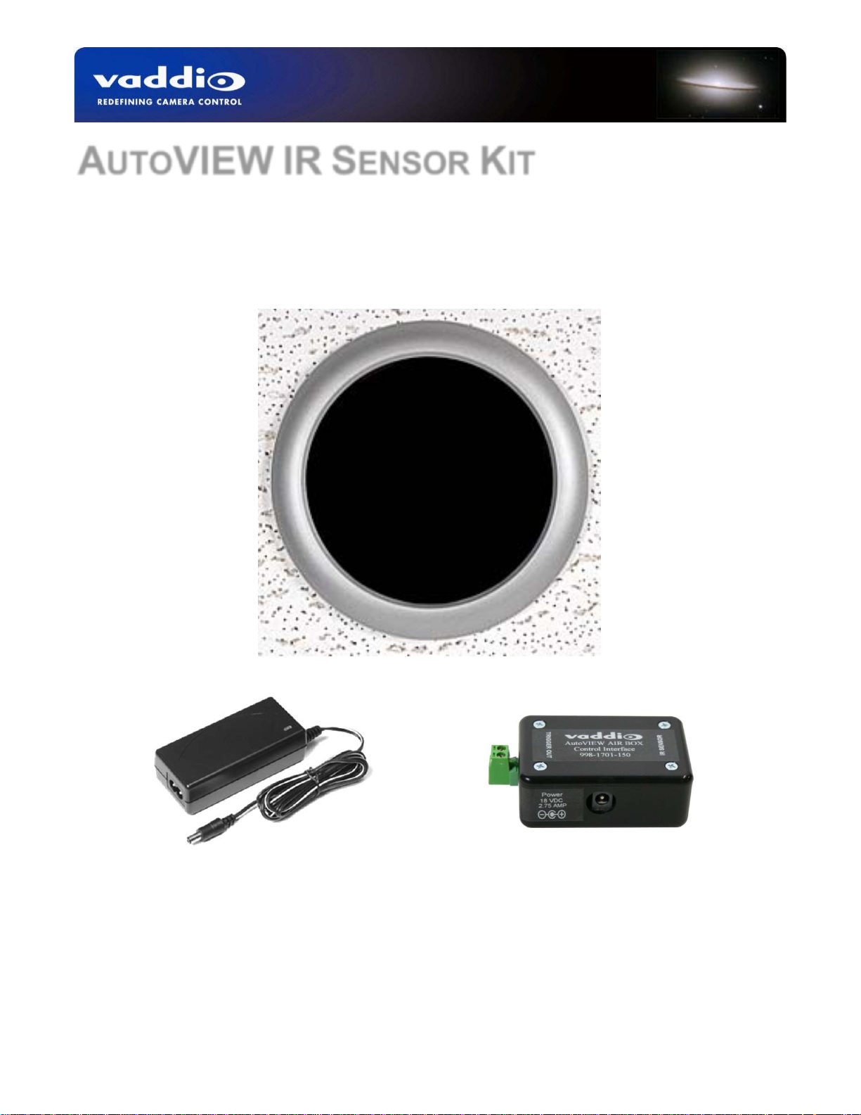
AUTOVIEW IR SENSOR KIT
Single Ceiling Mounted Active IR Sensor with AutoVIEW IR
Control Interface and Power Supply
P/N: 999-1701-100 North America
999-1701-101 International
©2012 Vaddio - All Rights Reserved ● AutoVIEW IR Sensor Kit ● Document Number 341-233-1 Rev. C
Page 2

AutoVIEW IR Sensor Kit
Inside Front Cover - Blank
AutoVIEW IR Sensor Kit Manual 341-233-1 Rev. C Page 2 of 8
Page 3
AutoVIEW IR Sensor Kit
p
AutoVIEW™ IR Sensor Kit
Single Ceiling Mounted Active IR Sensor with
AutoVIEW IR Control Interface and Power Supply
P/N: 999-1701-100 North America, 999-1701-101 Int’l
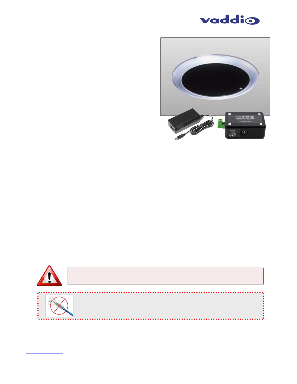
The Vaddio™ AutoVIEW IR Sensor Kit is a ceiling
mounted presenter camera control system that provides
for automated presenter control over the Vaddio family of
camera switching systems.
The Vaddio AutoVIEW IR Sensor Kit includes the ceiling
mounted active IR sensor with dark acrylic lens, the
AutoVIEW IR Control Interface and 18 VDC power supply
with power cord. This AutoVIEW IR Kit is compatible with
the following Vaddio automated presenter controlled
switchers and controllers;
ControlVIEW XHD
AutoPresenter
Hot-Shot Preset Camera Controller (for select
Polycom, Cisco/TANDBERG and LifeSize codecs)
ProductionVIEW series of video consoles including the
FX, HD, HD-SDI, HD MV and HD-SDI MV
The AutoVIEW IR Sensor Kit provides a simple contact closure to trigger any camera preset or video input switch
that these controllers and switchers can provide. The AutoVIEW IR Control Interface powers the IR Sensor via
the Cat-5e cable. When the IR sensor picks up the presenter passing under the sensor, a contact pair is relayed
down the Cat-5e through the AIR Box out of the Phoenix connector to the trigger input of the AutoPresenter. The
trigger will change the input and/or the camera’s PTZ position allowing for automated presenter camera control.
Intended Use:
Before operating the device, please read the entire manual thoroughly. The system was designed, built and
tested for use indoors, and with the provided power supply and cabling. The use of a power supply other than the
one provided or outdoor operation has not been tested and could damage the device and/or create a potentially
unsafe operating condition.
Important Safeguards:
Read and understand all instructions before using. Do not operate any device if it has been dropped or damaged.
In this case, a Vaddio technician must examine the product before operating. To reduce the risk of electric shock,
do not immerse in water or other liquids and avoid extremely humid conditions.
Use only the power supply provided with the system. Use of any unauthorized
power supply will void any and all warranties.
Save These Instructions:
The information contained in this manual will help you install and operate your product. If these instructions are
misplaced, Vaddio keeps copies of Specifications, Installation and User Guides and most pertinent product
drawings for the Vaddio product line on the Vaddio website. These documents can be downloaded from
www.vaddio.com free of charge.
AutoVIEW IR Sensor Kit Manual 341-233-1 Rev. C Page 3 of 8
Please do not use “pass-thru” type RJ-45 connectors. These pass-thru type connec tors do not
work well for professional installations and can be the cause of intermittent connections which
can result in the RS-232 control line failing and locking up, and/or compromising the HSDS™
signals. For best results please use standard RJ-45 connector s and test all cables for proper
in-outs prior to use and connection to Vaddio product.
Figure 1: The AutoVIEW IR Sensor, AutoVIEW IR (AIR)
Control Interface and 18 VDC Power Supply shown above
Page 4

AutoVIEW IR Sensor Kit
Unpacking:
Carefully remove the device and all of the parts from the packaging. Unpack and identify the following parts:
One (1) AutoVIEW Active IR Sensor (modified Optex with RJ-45 connector to support Cat-5e cabling)
One (1) Dark Acrylic Lens Cover
One (1) AutoVIEW Control Interface with 2-pin Phoenix type connector
One (1) 18VDC, 2.75 Amp Switching Power Supply
One (1) Power Cord (International version ships with UK and Euro power cables)
Installation:
Installation of the AutoVIEW IR Presenter Camera Control System is as unique as it is simple. With any Vaddio
product, understanding the key system components is essential.
IR Sensors:
The Optex OA-70CS sensors provided with the AutoVIEW IR Sensor Kit are active infrared sensors using near
infrared reflection to actively sense the presence of something or someone within the sensing zone. Much like
automatic door sensors for grocery or department stores, the sensors detect the presence of a person within a
zone which can be tuned for the specific environment in which it operates. The Optex owner’s manual provided
with each sensor details the installation and proper adjustment of the sensor.
AutoVIEW IR Sensor Dimensions and Features:
Modified to RJ-45
AutoVIEW IR Sensor Kit Manual 341-233-1 Rev. C Page 4 of 8
Page 5

AutoVIEW IR Sensor Kit
The AutoVIEW IR Control Interface:
The AutoVIEW IR (AIR Box) Control interface supplies power the IR Senor and returns a closure pair (short to
ground) to the TRIGGER OUT which can be connected into any Vaddio or other device with a trigger input.
The plastic box for the control interface is approximately 3” (76.2mm) W x 2” (50.8mm) H x 1” (25.4mm) D and
have the following attributes:
AutoVIEW IR (AIR) Control Interface ISO View
2- Pin
Phoenix
Connector
AutoVIEW IR (AIR) Control Interface Top View
2- Pin
Trigger
Out
Trigger
Out
Cat-5e
To IR
Sensor
18VDC
Power Input
18VDC
Power
Input
RJ-45 Jack
Cat-5e to IR
Sensor
Basic System Configuration
Single IR Sensor Detects Presenter within the IR Zone and provides a trigger output to the AutoPresenter to
change the camera and PTZ position preset.
Vaddio HD-20 HD Cameras
AutoVIEW
IR Sensor
Control &
HD Video
Trigger OUT
to Trigger IN
2-wires
AutoVIEW IR Air
Box IR Control
Interface
Closure
Single Cat-5e
Cable - Up to 100
(30.48m)
AutoPresenter
Also works with:
ControlVIEW XHD
Hot-Shot Camera Preset Controller for
Codecs
ProductionVIEW Series Seamless Switcher
and Controllers
Any control system that can accept a short
to ground trigger
Power
AutoVIEW IR Sensor Kit Manual 341-233-1 Rev. C Page 5 of 8
Page 6

AutoVIEW IR Sensor Kit
Basic Installation
The AutoVIEW IR Sensor is a modified Optex Sensor usually used in automatic door systems.
1) Affix the mounting template to the sensor mounting position
2) Drill or cut a 5-1/8” (130mm) round mounting hole for the sensor
Recommended distance to the nearest wall is 12” (304.8mm)
Side view of
sensor
Spring Steel
mounting
clips
Drill a 5-1/8”
hole for the
sensor
3) Hold the sensor, keeping the door markers pointed toward the nearest wall
4) Connect the Cat-5e cable
5) Press the spring steel mounting clips against the side of the sensor and place sensor in the mounting
hole. The spring steel clips will provide a tension fit. Not tile race is needed
6) Adjust the sensor according to the Otpex manual and click on the front acryilic lens cover.
7)
WALL
Set the door markers on the sensor
toward the nearest wall
8) Connect the Cat-5e cable from the AutoVIEW IR Sensor to the end of the AutoVIEW IR Control Interface
clearly marked IR Sensor.
9) Connect to the 2-wire trigger OUT on the AutoVIEW IR Control Interface to the trigger IN that is to be
controlled.
10) Test and adjust to requirements.
AutoVIEW IR Sensor Kit Manual 341-233-1 Rev. C Page 6 of 8
Page 7

AutoVIEW IR Sensor Kit
Warranty Information:
(See Vaddio Warranty, Service and Return Policies posted on vaddio.com for complete details):
Hardware* Warranty: One year limited warranty on all parts. Vaddio warrants this product against defects in materials and
workmanship for a period of one year from the day of purchase from Vaddio. If Vaddio receives notice of such defects during
the warranty period, they will, at their option, repair or replace products that prove to be defective. Please see Vaddio’s
Service Terms and Conditions at vaddio.com for specific details and policies.
Exclusions: The above warranty shall not apply to defects resulting from: improper or inadequate maintenance by the
customer, customer applied software or interfacing, unauthorized modifications or misuse, operation outside the normal
environmental specifications for the product, use of the incorrect power supply, improper extension of the power supply cable
or improper site operation and maintenance.
Vaddio Customer Service: Vaddio will test, repair, or replace the product or products without charge if the unit is under
warranty and is found to be defective. If the product is out of warranty, Vaddio will test then repair the product or products. The
cost of parts and labor charge will be estimated by a technician and confirmed by the customer prior to repair. All components
must be returned for testing as a complete unit. Vaddio will not accept responsibility for shipment after it has left the premises.
Vaddio Technical Support: Vaddio technicians will determine and discuss with the customer the criteria for repair costs
and/or replacement. Vaddio Technical Support can be contacted through one of the following resources: e-mail support at
support@vaddio.com or online at www.vaddio.com.
Return Material Authorization (RMA) Number: Before returning a product for repair or replacement, request an RMA from
Vaddio’s technical support. Provide a technician with a return phone number, e-mail address, shipping address, and product
serial numbers and describe the reason for repairs or returns as well as the date of purchase and proof of purchase. Include
your assigned RMA number in all correspondence with Vaddio. Write your assigned RMA number on the shipping label of the
box when returning the product. All products returned for credit are subject to a restocking charge without exception.
Voided Warranty: The warranty does not apply if the original serial number has been removed or if the product has been
disassembled or damaged through misuse, accident, modifications, or unauthorized repair. Cutting the power supply cable on
the secondary side (low voltage side) to extend the power to the device (camera or controller) voids the warranty for that
device.
Shipping and Handling: Vaddio will not pay for inbound shipping transportation or insurance charges or accept any
responsibility for laws and ordinances from inbound transit. Vaddio will pay for outbound shipping, transportation, and
insurance charges for all items under warranty but will not assume responsibility for loss and/or damage by the outbound
freight carrier.
• If the return shipment appears damaged, retain the original boxes and packing material for inspection by the carrier. Contact
your carrier immediately.
Products Not Under Warranty: Payment arrangements are required before outbound shipment for all out of warranty
products.
*Vaddio manufactures its hardware products from parts and components that are new or equivalent to new in accordance with industry standard practices.
Other General Information:
Care and Cleaning
Do not attempt to take this product apart at any time. There are no user-serviceable components inside.
Do not spill liquids in the product
Keep this device away from food and liquid
For smears or smudges on the product, wipe with a clean, soft cloth
Do not use any abrasive chemicals.
Operating and Storage Conditions:
Do not store or operate the device under the following conditions:
Temperatures above 40°C (104°F) or temperatures below 0°C (32°F)
High humidity, condensing or wet environments
In inclement weather
In swimming pools, rainforests or volcanos
Dry environments with an excess of static discharge
In outer space (re-entry not recommended)
Under severe vibration
AutoVIEW IR Sensor Kit Manual 341-233-1 Rev. C Page 7 of 8
Page 8

AutoVIEW IR Sensor Kit
©2014 Vaddio - All Rights Reserved. Reproduction in whole or in part without written permission is prohibited. Specifications and pricing are
AutoVIEW IR Sensor Kit Manual 341-233-1 Rev. C Page 8 of 8
subject to change without notice. Vaddio, ControlVIEW, AutoPresenter, Quick-Connect, AutoVIEW, ProductionVIEW, Hot-Shot and PowerRite
are registered trademarks of Vaddio. All other trademarks are property of their respective owners. Document Number 342-233-1 Rev C
Toll Free: 800-572-2011 ▪ Phone: 763-971-4400 ▪ FAX: 763-971-4464
www.vaddio.com
 Loading...