

Page 1

Complete Manual for the
RoboSHOT IW
Architectural PTZ Conferencing Camera
Document 411-0016-30 Rev B
September 2018
Page 2

Contents
Overview 1
What's in this Guide 2
Features 2
Unpacking the Camera 3
Camera Only 3
Camera Systems with OneLINK HDMI 4
Camera System with OneLINK Bridge 5
A Quick Look at the Camera and Enclosure 6
Installing the Camera 7
Don’t Void Your Warranty! 7
Cabling Notes 7
Selecting the Installation Area 8
Pre-Installation Functional Check 8
Basic Connections 9
RoboSHOT IW OneLINK Bridge System 9
RoboSHOT IW OneLINK HDMI System 9
RoboSHOT IW with Third-Party Connectivity Solution 9
Options for Power and Other Connections 10
Things You Will Need for the Installation 10
Installing the Power Source 10
Installing the Camera Enclosure 10
Before You Start 10
Installing the Camera Enclosure in an Unfinished Wall 11
Installing the Camera Enclosure in a Finished Wall 11
Installing the Camera 12
Installing the Interior Side Panels 12
Installing the Cover 12
Powering Up the Camera 13
Status Light 13
Using the IR Remote 14
IR Remote Cheat Sheet 14
IR Remote Details 15
Storing a Preset Using the Remote 15
Clearing a Preset Using the Remote 15
Web Interface 16
Getting the Camera's IP Address 16
Accessing the Web Interface 16
Browser Support 16
User Access 17
Administrative Access 18
ii
Page 3

Complete Manual for the RoboSHOT IW Architectural PTZ Conferencing Camera
Compact Menu View 18
Web Interface Cheat Sheet 19
System Administration 20
Changing the Camera's Hostname 20
Changing to a Static IP Address in a DHCP Network 21
Specifying Time Zone and NTP Server 21
Managing Access and Passwords 22
Disabling Telnet Access 22
Enabling or Requiring HTTPS 23
Adding Room Information to the Camera's Web Interface 24
Saving (Exporting) or Restoring (Importing)a Camera Configuration 25
Installing a Camera Firmware Update 25
Rebooting the Camera 26
Contacting Vaddio Technical Support 26
Accessing the Diagnostic Logs 27
Configuring Camera Behavior 28
Configuring IP Streaming 28
Setting up Streaming in Easy Mode 29
Setting up Streaming in Custom Mode 30
Streaming Protocol and URL 30
Adjusting the Focus 31
Lighting and Color Adjustments: Setting up Custom CCU Scenes 32
Setting the Custom Home Position and Other Preset Shots 34
Renaming Presets and Custom CCU Scenes 34
Setting the Speed for Manual Movements 35
Setting the Direction for Camera Movements 35
Software Switch Settings 36
Operating the Camera from the Web Interface 37
Switching the Camera Off or On (Standby) 37
Stop or Resume Sending Video (Mute) 37
Moving the Camera 38
Zooming In or Out 38
Moving the Camera to a Preset Position 38
Adjusting the Color and Lighting 38
Telnet Command Reference 39
camera home 40
camera pan 40
camera tilt 41
camera zoom 42
camera focus 43
camera preset 44
iii
Page 4

Complete Manual for the RoboSHOT IW Architectural PTZ Conferencing Camera
camera ccu get 45
camera ccu set 46
camera ccu scene 47
camera glass mode 47
camera glass state 48
camera resolution 49
camera led 50
camera standby 50
camera recalibrate 51
streaming settings get 51
network settings get 52
network ping 52
system reboot 53
system factory-reset 53
version 54
history 54
help 55
exit 55
RS-232 Serial Command Reference 56
Camera Movement, Zoom, and Focus Commands 56
Movement, Zoom, and Focus Inquiry Commands 58
Color and Light Management Commands 59
Shutter Speed Values (CAM_Shutter) 61
Iris Values (CAM_Iris) 62
Iris Gain and Gain Limit Values (CAM_Gain) 62
Color and Light Management Inquiry Commands 63
Other Commands 63
Other Inquiry Commands 64
Specifications 65
Troubleshooting and Care 66
Check the Status Light First 66
Power/Responsiveness Issues 66
Video and Streaming Issues 67
Camera Control and Other Issues 67
Restoring Factory Settings from the Web Interface 68
Correcting a Motor Calibration Fault 68
Operation, Storage, and Care 69
Compliance Statements and Declarations of Conformity 70
FCC Part 15 Compliance 70
ICES-003 Compliance 70
European Compliance 71
iv
Page 5

Complete Manual for the RoboSHOT IW Architectural PTZ Conferencing Camera
Warranty Information 72
Photo Credits 73
Index 74
v
Page 6

Overview
This guide describes installation and related information for the RoboSHOT®In-Wall architectural PTZ
conferencing camera:
n RoboSHOT IW with smart glass, black – 999-9965-100 (North America); 999-9965-101 (Europe/UK)
n RoboSHOT IW with smart glass, primer coated – 999-9965-150 (North America); 999-9965-151 (Europe
and UK)
n RoboSHOT IW OneLINK® HDMI System with smart glass, black – 999-9965-200 (North
America);999-9965-201 (Europe and UK)
n RoboSHOT IW OneLINK HDMI System with smart glass, primer coated – 999-9965-250 (North
America);999-9965-251 (Europe and UK)
n RoboSHOT IW OneLINK Bridge System with smart glass, black – 999-9965-300 (North America);999-
9965-301 (Europe and UK)
n RoboSHOT IW OneLINK Bridge System with smart glass, primer coated – 999-9965-350 (North
America);999-9965-351 (Europe and UK)
n RoboSHOT IW with safety glass, black – 999-9966-100 (North America); 999-9966-101 (Europe/UK)
n RoboSHOT IW with safety glass, primer coated – 999-9966-150 (North America); 999-9966-151
(Europe and UK)
n RoboSHOT IW OneLINK® HDMI System with safety glass, black – 999-9966-200 (North
America);999-9966-201 (Europe and UK)
n RoboSHOT IW OneLINK HDMI System with safety glass, primer coated – 999-9966-250 (North
America);999-9966-251 (Europe and UK)
n RoboSHOT IW OneLINK Bridge System with safety glass, black – 999-9966-300 (North America);999-
9966-301 (Europe and UK)
n RoboSHOT IW OneLINK Bridge System with safety glass, primer coated – 999-9966-350 (North
America);999-9966-351 (Europe and UK)
1
Page 7

Complete Manual for the RoboSHOT IW Architectural PTZ Conferencing Camera
What's in this Guide
This guide covers:
n Unpacking
n Physical features
n Installation
n Controlling the camera using the IR remote
n Web interface:system administration and configuration
n Telnet and RS-232 API references
n Specifications
n Troubleshooting
n Warranty and compliance/conformity information
For your convenience, the information you need to install this product is also available in the smaller, standalone Installation Guide for the RoboSHOT IW Architectural PTZ Conferencing Camera, which
covers unpacking, physical features, switch settings, installation, and initial power-up.
Download manuals, dimensional drawings, and other information from www.vaddio.com/support.
Features
n Attractive, ADA-compliant recessed design
n Fully enclosed with smart glass cover (frosted when the camera is not sending video) or tamper-
resistant safety glass cover
n Exmor® 1/2.8 type, high-speed, low-noise image sensor for 2.38 megapixels total, full HD (native
1080p/60)
n 10x optical zoom with horizontal field of view from 67° (wide end) to 7.6° (tele end)
n Superior low-light performance (0.4 Lux)
n Web interface for remote administration and operation, integration-ready Telnet and serial RS-232
control, presenter-friendly IR remote control
n Use with a OneLINK device for power, video, and control:
o
OneLINKHDMI – uncompressed HDMI video, bidirectional RS-232 connectivity for camera control
via third-party equipment, passes IP stream from the camera
o
OneLINK Bridge – OneLINKHDMIcapabiliities plus uncompressed USB 3.0 streaming, HD-SDI
output, and audio routed up to the camera and injected into the IP stream
2
Page 8

Complete Manual for the RoboSHOT IW Architectural PTZ Conferencing Camera
Unpacking the Camera
Make sure you receive all the items you expected.
Camera Only
RoboSHOT IW with Smart Glass
999-9965-100 – RoboSHOT IW with Smart Glass, Black, North America
999-9965-150 – RoboSHOT IW with Smart Glass, Primer Coated, North America
999-9965-101 – RoboSHOT IW with Smart Glass, Black, Europe/UK
999-9965-151 – RoboSHOT IW with Smart Glass, Primer Coated, Europe/UK
RoboSHOT IW with Clear Glass
999-9966-100 – RoboSHOT IW with Clear Glass, Black, North America
999-9966-150 – RoboSHOT IW with Clear Glass, Primer Coated, North America
999-9966-101 – RoboSHOT IW with Clear Glass, Black, Europe/UK
999-9966-151 – RoboSHOT IW with Clear Glass, Primer Coated, Europe/UK
n Camera
n Enclosureassembly, black or primed
o
Back box
o
Interior side plates, right and left
o
Side brackets, qty. 2
o
Drywall clips, qty. 4
o
Screws, 6-32, 1/4 in, qty. 10
o
Screws, 6-32, 3/8 in, qty. 8
o
Screws, 10-24, 1 in, qty. 4
n Front frame, black or primed, with smart glass (opaque) or clear glass
n PoE+ mid-span power injector with AC cord set(s)
n Vaddio IR Remote Commander
n Installation Guide 411-0016-31 for RoboSHOT IW
3
Page 9

Complete Manual for the RoboSHOT IW Architectural PTZ Conferencing Camera
Camera Systems with OneLINK HDMI
RoboSHOT IW OneLINK HDMI System with Smart Glass
999-9965-200 – RoboSHOT IW OneLINK HDMI System with Smart Glass, Black, North America
999-9965-250 – RoboSHOT IW OneLINK HDMI System with Smart Glass, Primer Coated, North America
999-9965-201 – RoboSHOT IW OneLINK HDMI System with Smart Glass, Black, Europe/UK
999-9965-251 – RoboSHOT IW OneLINK HDMI System with Smart Glass, Primer Coated, Europe/UK
RoboSHOT IW OneLINK HDMI System with Clear Glass
999-9966-200 – RoboSHOT IW OneLINK HDMI System with Clear Glass, Black, North America
999-9966-250 – RoboSHOT IW OneLINK HDMI System with Clear Glass, Primer Coated, North America
999-9966-201 – RoboSHOT IW OneLINK HDMI System with Clear Glass, Black, Europe/UK
999-9966-251 – RoboSHOT IW OneLINK HDMI System with Clear Glass, Primer Coated, Europe/UK
n Camera
n Enclosureassembly, black or primed
o
Back box
o
Interior side plates, right and left
o
Side brackets, qty. 2
o
Drywall clips, qty. 4
o
Screws, 6-32, 1/4 in, qty. 10
o
Screws, 6-32, 3/8 in, qty. 8
o
Screws, 10-24, 1 in, qty. 4
n Front frame, black or primed, with smart glass (opaque) or clear glass
n Vaddio IR Remote Commander
n Installation Guide 411-0016-31 for RoboSHOT IW
n OneLINK HDMI receiver
n Power supply, 48 VDC/1.36 A, with AC cord set(s)
n EZCamera RS-232 control adapter
n Quick-Start Guide 411-0019-01 for OneLINKHDMI
4
Page 10

Complete Manual for the RoboSHOT IW Architectural PTZ Conferencing Camera
Camera System with OneLINK Bridge
RoboSHOT IW OneLINK Bridge System with Smart Glass
999-9965-300 – RoboSHOT IW OneLINK Bridge System with Smart Glass, Black, North America
999-9965-350 – RoboSHOT IW OneLINK Bridge System with Smart Glass, Primer Coated, North America
999-9965-301 – RoboSHOT IW OneLINK Bridge System with Smart Glass, Black, Europe/UK
999-9965-351 – RoboSHOT IW OneLINK Bridge System with Smart Glass, Primer Coated, Europe/UK
RoboSHOT IW OneLINK Bridge System with Clear Glass
999-9966-300 – RoboSHOT IW OneLINK Bridge System with Clear Glass, Black, North America
999-9966-350 – RoboSHOT IW OneLINK Bridge System with Clear Glass, Primer Coated, North America
999-9966-301 – RoboSHOT IW OneLINK Bridge System with Clear Glass, Black, Europe/UK
999-9966-351 – RoboSHOT IW OneLINK Bridge System with Clear Glass, Primer Coated, Europe/UK
n Camera
n Enclosureassembly, black or primed
o
Back box
o
Interior side plates, right and left
o
Side brackets, qty. 2
o
Drywall clips, qty. 4
o
Screws, 6-32, 1/4 in, qty. 10
o
Screws, 6-32, 3/8 in, qty. 8
o
Screws, 10-24, 1 in, qty. 4
n Front frame, black or primed, with smart glass (opaque) or clear glass
n Vaddio IR Remote Commander
n Installation Guide 411-0016-31 for RoboSHOT IW
n OneLINK Bridge AV interface
n Power supply, 48 VDC/1.36 A, with AC cord set(s)
n USB 3.0 A to B cable, 6 ft. (1.8 m)
n 3-position Phoenix connector plug, 3.5 mm, qty. 4
n EZCamera RS-232 control adapter
n Quick-Start Guide 411-0009-01 for OneLINK Bridge
5
Page 11

Complete Manual for the RoboSHOT IW Architectural PTZ Conferencing Camera
A Quick Look at the Camera and Enclosure
Camera and Lens – The 10x optical zoom lens and Exmor® 1/2.8 type, high-speed, low-noise image
sensor deliver crisp full-HD video.
Frame – Metal frame and glass window.
Interior side panels – No wiring is visible when the camera is installed.
Camera platform – Houses the electronics.
IR window – A sensor in the front of the camera platform receives signals from the remote. Make sure
there's nothing directly in front of the camera platform, and point the remote at the camera.
Status indicator – The multicolored LED indicates the camera's current state.
n Blue: Normal operation (blinks once when the camera receives a command from the remote)
n Red: On-air tally
n Blinking blue or blinking red:Video is muted
n Purple: In standby mode or booting
n Yellow: Firmware update in progress
n Blinking yellow: Motor calibration fault
Note
By default, the camera's status light is active during normal operation; however, it can be configured to
remain off when the camera is powered up. The camera may be sending video even if the indicator light is
off.
If the camera has a smart-glass cover, the cover is frosted when the camera is in standby mode (not
sending video). The glass remains clear when video is muted; however, if enabled, the status light blinks.
6
Page 12

Complete Manual for the RoboSHOT IW Architectural PTZ Conferencing Camera
Installing the Camera
This section covers:
n Selecting the location for the camera
n Installing the enclosure
n Connecting the camera
n Completing the installation
Don’t Void Your Warranty!
Caution
This product is for indoor use. Use an appropriate protective enclosure if installing it outdoors or in a humid
environment.
Do not install or operate this product if it has been dropped, damaged, or exposed to liquids. If any of these
things happen, return it to Vaddio for safety and functional testing.
Use the power source included with or recommended for use with this product. Using the wrong power
supply will void the warranty, and could create unsafe operating conditions or damage the product. Power
supplies for different products may look nearly identical – always check the label for the output voltage.
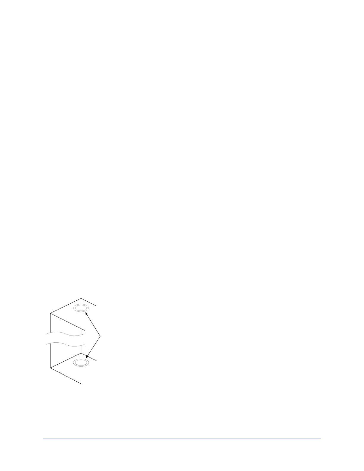
Cabling Notes
Use Cat-5e or better cable. We recommend using high-quality connectors and a high-quality crimping tool.
Caution
Do not use pass-through RJ-45 connectors. If they are crimped incorrectly, they can damage the
connectors on the product, cause intermittent connections, and degrade signal quality. Physical damage to
the connectors may void your warranty.
Intact – will make reliable contact
with cable connector
Damaged – Bent contact fingers
will NOT make reliable contact
with cable connector
We recommend shielded cabling if the cables will be coiled, run tightly with other cables, or placed close
sources of electromagnetic interference such as power lines.
Caution
Check your cables. Connecting a cable to the wrong port or using the wrong pin-out can result in equipment
damage and will void the warranty.
Pro Tip
To prevent tragic mishaps, label both ends of every cable.
7
Page 13

Complete Manual for the RoboSHOT IW Architectural PTZ Conferencing Camera
Selecting the Installation Area
Install the camera in a location that meets the following requirements.
Note
Work must conform to local building codes and should be performed by qualified personnel.
Environment: This product is designed for indoor use only.
Structural requirements:
n The enclosure is designed to be mounted into a wood or steel stud wall 16 in. (40.6 cm) on center, or to
a drywall surface at least 0.5 in (1.27 cm) thick.
n If the wall studs are on greater than 16 in. centers, you will need to mount to drywall on at least two
corners.
Safety: Ensure that no obstructions of any kind are present in the area that the camera enclosure will be set
into.
Warning
Before cutting the opening for the camera enclosure, ensure that no wiring and no pipes are present in or
immediately adjacent to the area that the camera enclosure will be set into.
Cutting or drilling into electrical wiring can cause electrical shock or fire, resulting in death, injury, and
damage to the building.
Cutting or drilling into gas pipes can cause explosion or fire, resulting in death, injury, and damage to the
building.
Cutting or drilling into water or wastewater lines can result in injury and damage to the building.
Performance:
n Choose a camera mounting location that will optimize camera performance. Consider camera viewing
angles, lighting conditions, and line-of-sight obstructions where the camera is to be mounted.
n If the remote control will be used, ensure that nothing blocks the IRlens in the camera enclosure.
Pre-Installation Functional Check
Before you install the camera, verify that it powers up and sends video. Referring to the basic connection
diagrams, connect the camera and verify that video is available on the connected display.
When you have verified that the camera operates properly, disconnect it and continue with the installation.
8
Page 14

Complete Manual for the RoboSHOT IW Architectural PTZ Conferencing Camera
Basic Connections
Connecting the camera is simple – just connect the cable to the OneLINK device or to the Power + Data
connector of the mid-span power injector. The following diagrams show basic connections to other
components of the room system.
RoboSHOT IW OneLINK Bridge System
RoboSHOT IW OneLINK HDMI System
RoboSHOT IW with Third-Party Connectivity Solution
9
Page 15
Complete Manual for the RoboSHOT IW Architectural PTZ Conferencing Camera
Options for Power and Other Connections
Connect the camera to a OneLINK device – A single Cat-5e (or better) cable provides power to the
camera, along with HDBaseT network and video connectivity. Network, video output, and RS-232 control
are connected at the OneLINK device.
Use a PoE+ power injector – Connect to the network or to an HDBaseT-capable third-party control
device through a PoE+ power injector.
Things You Will Need for the Installation
Before you start, be sure you have what you need:
n Access to the area above the ceiling
n Plumb line
n Pencil
n Appropriate tools for cutting a hole in the ceiling
n #2 Phillips screwdriver
n Conduit box, if required
Installing the Power Source
You can connect the camera to the IP network using a mid-span power injector, or you can connect it to a
OneLINK device. If you use a OneLINK device, it may be installed up to 328 ft (100 m) from the camera.
1. Install the power injector or OneLINK device before installing the camera enclosure.
2. Route the camera cable from the power injector or OneLINK device to the camera enclosure location.
Installing the Camera Enclosure
The RoboSHOT IW camera may be installed either in an unfinished wall, before the drywall is in place, or in
a finished wall. In either situation, the installation is in three steps:
n Install the enclosure using the appropriate procedure.
n Install the camera in the enclosure.
n Install the cover.
Before You Start
Consider which direction the camera cable needs to enter the enclosure, and remove the knock-out tab
from either the upper or lower face of the enclosure.
10
Page 16
Complete Manual for the RoboSHOT IW Architectural PTZ Conferencing Camera
Installing the Camera Enclosure in an Unfinished Wall
Follow these steps if the drywall has not yet been installed.
1. Measure, mark, and level the mounting position between two studs.
2. Holding the enclosure in place against the wall studs, mark the locations for the holes.
3. Set the camera enclosure aside and drill the holes.
4. Fasten the camera enclosure to the wall studs.
5. Route the camera cable into the enclosure.
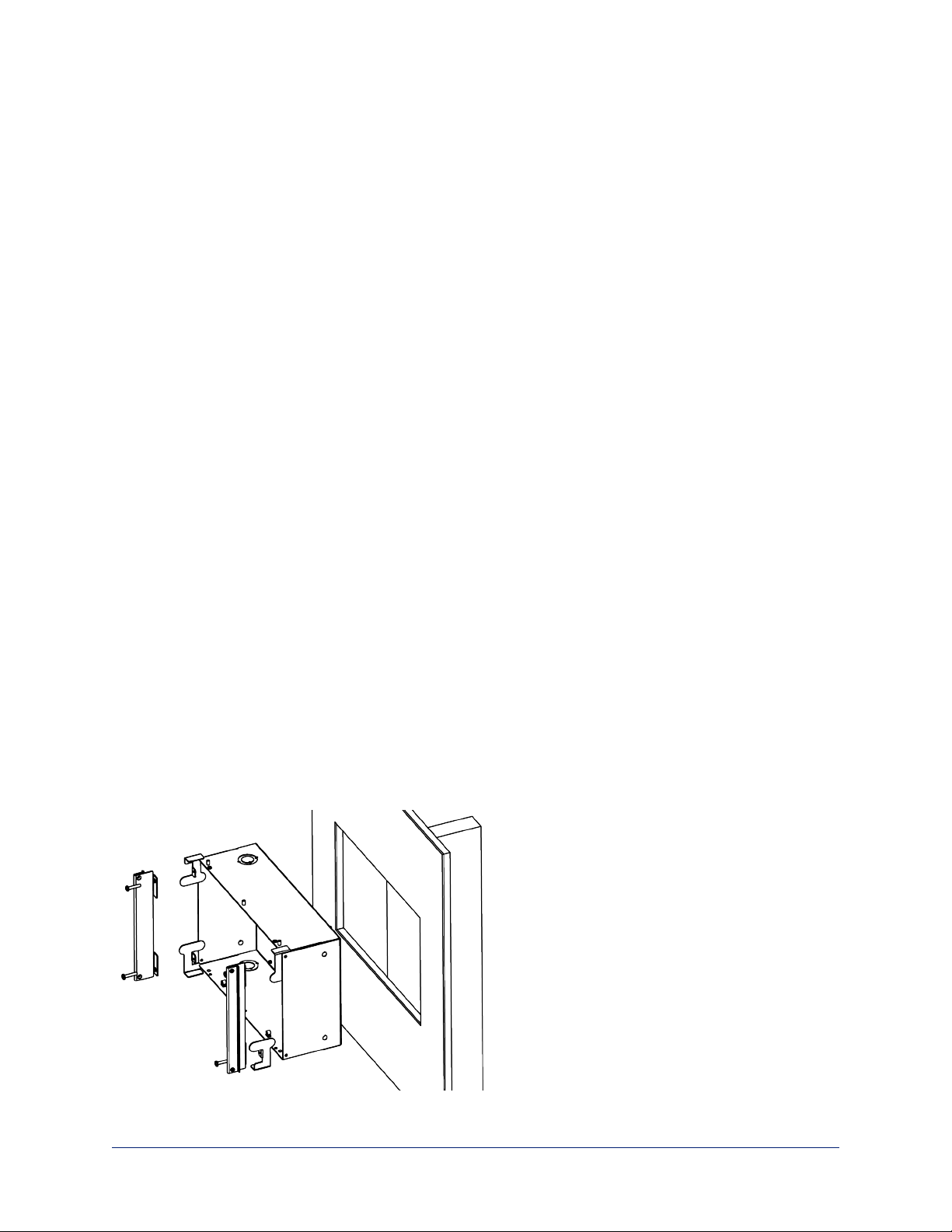
Installing the Camera Enclosure in a Finished Wall
Follow these steps if the drywall is in place.
Warning
Before cutting the opening for the camera enclosure, ensure that no wiring and no pipes are present in or
immediately adjacent to the area that the camera enclosure will be set into.
Cutting or drilling into electrical wiring can cause electrical shock or fire, resulting in death, injury, and
damage to the building.
Cutting or drilling into gas pipes can cause explosion or fire, resulting in death, injury, and damage to the
building.
Cutting or drilling into water or wastewater lines can result in injury and damage to the building.
1. Verify that no pipes or wiring pass through or immediately adjacent to the part of the wall where the
camera enclosure will be mounted.
2. Level, measure, and mark the cutting lines for the opening.
3. Cut the opening.
4. Slide the drywall clips into the corners of the enclosure.
Note
Although the drywall clips are not visually symmetrical, they can be installed with either curved surface
facing forward, depending on the corner in which they are placed.
5. Install the side brackets using 1/4 in. 6-32 screws.
6. Route the camera cable into the enclosure.
7. Slide the enclosure into place.
8. Use the 10-32 screws to attach the drywall clips to the side brackets. The clips tilt outward and engage
the drywall as you tighten the screws.
11
Page 17
Complete Manual for the RoboSHOT IW Architectural PTZ Conferencing Camera
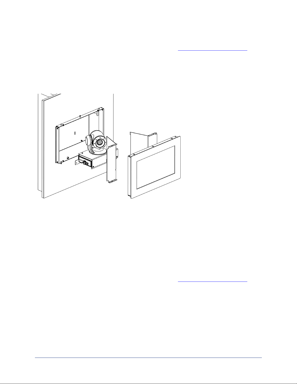
Installing the Camera
Do this only after verifying that the camera powers up properly. See Pre-Installation Functional Check for
details.
1. Place the camera assembly in the enclosure, with the face in front of the tabs. If the enclosure has a
smart glass cover, ensure that the cable for the cover panel is accessible.
2. Attach the camera to the back tabs using two 1/4 in. 6-32 screws.
3. Attach the camera to the front tabs using two 3/8 in. 6-32 screws.
4. Connect the camera cable.
Installing the Interior Side Panels
The two interior side panels are not interchangeable. The right side panel has a cut-out for the smart glass
cable.
To install each interior side panel:
1. Insert the tabs into the slots in the back of the enclosure.
2. Rotate the interior side panel into place. If the enclosure has a smart glass cover, ensure that the smart
glass cable passes freely through the opening in the right side panel.
3. Secure the side panel with 1/4 in. 6-32 screws.
Installing the Cover
Do this only after verifying that the camera powers up properly. See Pre-Installation Functional Check for
details.
1. If the enclosure has a smart glass front frame, connect its cable.
2. Position the front frame over the front of the enclosure, being sure that the cable (if used) is not pinched.
3. Attach the cover using 3/8 in. 6-32 screws.
12
Page 18

Complete Manual for the RoboSHOT IW Architectural PTZ Conferencing Camera
Powering Up the Camera
Connect camera power.
The camera will run a self-test routine and move to its home position. This will take a few seconds.When
the camera is initialized and ready, video is available and the status light is blue. At this point, the camera is
ready to accept control information.
Note
Wait until the camera finishes initializing before trying to operate or control it.
Status Light
The light in the camera's base indicates its current state.
n Blue: Normal operation (blinks once when the camera receives a command from the remote)
n Red: On-air tally
n Blinking red:Video is muted (UC LED color scheme only)
n Purple: In standby mode or booting
n Yellow: Firmware update in progress
Caution
Do not remove power or reset the camera while the indicator is yellow, showing a firmware update in
progress. Interrupting a firmware update can make the camera unusable.
Note
By default, the camera's status light is active during normal operation; however, it can be configured to
remain off when the camera is powered up. The camera may be sending video even if the indicator light is
off.
13
Page 19

Complete Manual for the RoboSHOT IW Architectural PTZ Conferencing Camera
Using the IR Remote
The IR remote provides basic camera control for end users.
IR Remote Cheat Sheet
What do you need to do? Button(s)
Power on or standby Power (green button at top right)
Select the camera to control (if this
remote controls more than one)
Discover the camera's IP address Data Screen button (top left) – press and hold for 3
Move the camera Arrow buttons and Home button (dark red)
Move the camera to a preset position Position Preset buttons 1 through 6 (bottom two rows)
Focus the camera Auto Focus button (near arrow buttons)
Control zoom speed Zoom Speed buttons - Slow T and W, Fast T and W for
Adjust for excess light behind the
camera's subject
Correct a motor calibration fault
condition (blinking yellow light)
Camera Select buttons 1 through 3 (second row of
buttons)
seconds.
Manual Focus buttons Near and Far (below Zoom
Speed buttons)
telephoto and wide-angle modes (light gray)
Back Light button (top center)
Pan-Tilt Reset button (center right, beside arrow
buttons)
14
Page 20

Complete Manual for the RoboSHOT IW Architectural PTZ Conferencing Camera
IR Remote Details
The Vaddio remote provides the following functions:
Power – Switch the selected camera on or off.
Power indicator – Lights momentarily when you press a button.
Back Light – Use or turn off Back Light Compensation.
Data Screen – Display the camera’s IP address and MAC address. Press this button
again to dismiss the display.
Camera Select – In multi-camera installations, selects the camera to be controlled.
See Camera Settings for information on configuring the camera as camera 1, 2, or 3.
Pan/Tilt (arrow button) controls and Home button – Control the camera’s
position.
Rev. Pan and Std. Pan– Control how the camera responds to the arrow buttons.
Helpful for ceiling-mounted cameras and for presenters who are controlling the
camera.
Pan/Tilt Reset – Recalibrate the pan and tilt motors. If the camera gets jostled, you
may need to push this button to ensure that the camera moves accurately to its home
and preset positions.
Auto Focus – Switch the camera to Auto-Focus mode.
Zoom Speed – Select Slow or Fast movements for telephoto and wide-angle shots.
n T (slow and fast) – Telephoto
n W (slow and fast) – Wide-angle
Manual Focus – Switch the camera to Manual Focus mode.
Near (-) adjustment – Moves the focus nearer when in manual focus mode.
Far (+) adjustment – Moves the focus farther when in manual focus mode.
Preset – Save the camera’s current position as one of the numbered presets.
Reset – Clear a saved preset.
Position Presets 1 through 6 – Move the camera to a predefined position, or specify the preset to save or
clear.
The web interface offers greater control over camera movements to presets, and provides additional
presets.
Storing a Preset Using the Remote
Position the camera. Then hold down the Preset button and press one of the numbered preset buttons.
Clearing a Preset Using the Remote
Press and hold the Reset button while pressing the preset number you want to clear.
15
Page 21

Complete Manual for the RoboSHOT IW Architectural PTZ Conferencing Camera
Web Interface
The camera's web interface allows control via a network connection, using a browser. Password-protected
pages provide administrative access to tasks such as setting passwords, changing the IP address,
viewing diagnostics, and installing firmware updates. The user login (or guest access, if it is
enabled)provides access to camera controls similar to those available from the IR remote.
You will need to know the camera's IP address to use its web interface. If the network has a DHCP server,
the camera will get its IP address, gateway and routing information automatically and you will be able to
browse to it. If not, you will need to configure the camera to use a static IP address.
The OneLINK device powering the camera has its own web interface. Refer to the appropriate OneLINK
manual for information on its web interface.
Getting the Camera's IP Address
You will need to be able to view the camera's video output.
1. Press the Data Screen button on the remote. The display presents the camera's IP address and MAC
address.
2. Press the Data Screen button again to dismiss the information.
If the address is 169.254.1.1, the camera is using its default IP address. This usually means one of these
things:
n The network automatically assigns IP addresses, but the camera is not connected to the network.
n The network does not automatically assign IP addresses, and you need to configure the camera for the
network. See Configuring the Camera with a Static IP Address.
Accessing the Web Interface
Enter the IP address or hostname in your browser's address bar. You may need to enter http:// or
https:// as a prefix to keep the browser from treating it as a search query.
(Example:http://10.30.200.125)
Browser Support
We have tested this product with these web browsers:
n Chrome®
n Microsoft® Internet Explorer®
n Safari®
n Firefox®
We test using the browser version available from the vendor at that time. Older versions of these browsers
are likely to work, and other browsers may also work.
16
Page 22

Complete Manual for the RoboSHOT IW Architectural PTZ Conferencing Camera
User Access
By default, the web interface opens to the Controls page, but the camera can be configured to require a
user login. The default user password is password, but this can be changed. Check with the system
administrator if the camera's web interface requires you to log in.
Only the Controls page is available with user-level access.
Your camera's Controls page may look somewhat different.
17
Page 23

Complete Manual for the RoboSHOT IW Architectural PTZ Conferencing Camera
Administrative Access
If you are on the Controls screen, you’re logged in at the user level, or guest access is enabled and you’re
not logged in at all.
Open the menu to log on as Admin. The default admin password is password, but this can be changed.
Your camera's web interface may look somewhat different from this image.
Note
For best security, Vaddio strongly recommends changing the user and admin passwords from
the default. Using the default passwords leaves the product vulnerable to tampering.
As Admin, you have access to the following pages:
n Camera – Additional control over camera behavior related to camera movement and color management.
n Streaming – Set up IP (H.264) streaming.
n Room Labels – Add helpful information the web interface screens, such as conference room name and
the in-house number for AV assistance.
n Networking – Ethernet configuration.
n Security – Set passwords and manage guest access.
n Diagnostics – Access to logs for troubleshooting.
n System – Reboot, restore defaults, view switch settings, and run updates.
n Help – Tech support contact information.
Compact Menu View
By default, the navigation buttons in the camera's administrative interface display an icon and a text label.
You can also select the compact view of the menu buttons along with the standard view. The button at the
bottom of the menu toggles between the two views.
18
Page 24

Complete Manual for the RoboSHOT IW Architectural PTZ Conferencing Camera
Web Interface Cheat Sheet
Where to find the camera controls you need right now.
What do you need? Go to this screen
Camera operation
n Stop sending video (video mute)
n Make the glass opaque for privacy (Manual glass control must be
(any page)
enabled)
n Enter or exit standby mode
Camera operation
n Move or zoom the camera manually
n Move to a camera preset (Presets section, if available)
n Select the appropriate lighting adjustments (CCU Scenes section,
Controls (user or guest access) or
Camera (admin access)
if available)
Camera behavior and adjustments
n Set or clear presets
n Set the speed for pan, tilt, or zoom motions
n Focus the camera
n Work with color and lighting adjustments (CCU scenes)
Advanced camera settings
n Super-wide field of view
n Indicator light – enable/disable; select color scheme
n HDMIcolor space (YCbCr or sRGB; default is YCbCr)
n Codec control mode
n Glass control mode - automatic or manual
n Video output resolution
Camera
System (DIP switches tab)
Read-outs of the camera's hardware switch settings System (DIP switches tab)
Access management
n Guest access
n Account passwords
n Idle session time-out
n Telnet access enabled/disabled
n Advanced security settings
IP streaming settings
n Quality, resolution, and frame rate
n Streaming URL and path
IP settings
n Hostname
n DHCP or static addressing
n Static: IP address, subnet mask, gateway
Security
Streaming
Networking
Time zone and NTP server (source for system time/date)
Information about the camera location
Room Labels
Help desk phone number for end users
Vaddio Technical Support contact information Help
Diagnostic logs Diagnostics
19
Page 25

Complete Manual for the RoboSHOT IW Architectural PTZ Conferencing Camera
System Administration
Administrative tasks are on these pages of the web interface:
n Networking – Ethernet configuration, time zone and NTP server
n Security – Passwords, guest access, other IT security-related settings
n Room Labels – Helpful information to display in the web interface
n System – Controls to reboot, reset to factory defaults, and run firmware updates, access to soft DIP
switches
n Help – Contact information for Vaddio Technical Support and a link to the documentation for this
product
n Diagnostics – Logs to help Vaddio Technical Support troubleshoot issues
Changing the Camera's Hostname
NETWORKING PAGE
If your network supports hostname resolution, you may find it convenient to change the camera's
hostname to something easy to remember, such as camera-center-boardroom.
Work with your IT department to ensure that the new hostname conforms to the organization's naming
conventions.
20
Page 26

Complete Manual for the RoboSHOT IW Architectural PTZ Conferencing Camera
Changing to a Static IP Address in a DHCP Network
NETWORKING PAGE
In a network that assigns IP addresses automatically, the camera's IP address may change from time to
time. To keep this from happening, set the IP address to Static. Do not change the IP address, subnet
mask, or gateway.
Specifying Time Zone and NTP Server
NETWORKING PAGE
Using automatic NTP updating ensures that the timestamps in the camera's diagnostic log are accurate.
Specifying your time zone may make it easier to match logged events with other actions and external
events.
1. To make the time zone and NTP server editable, enable Automatic NTP Updating.
2. Select the desired time zone from the list.
3. If desired, specify the NTP server to use. Otherwise, use the default.
You may need to refresh the system time display.
21
Page 27

Complete Manual for the RoboSHOT IW Architectural PTZ Conferencing Camera
Managing Access and Passwords
SECURITY PAGE
Set the camera according to your organization's security policies:
n Allow or deny access to the Camera screen without logging on (Allow Guest Access)
n Set whether inactive sessionslog off automatically or not (Automatically Expire Idle Sessions)
n Change the password for the admin account
n Change the password for the user account
n Allow or disable access via Telnet (by default, access via Telnet is enabled)
n Require HTTPS for web access (by default, HTTP is also permitted)
Note
Consult your network security specialist before changing any of these settings.
Note
For best security, Vaddio strongly recommends changing the user and admin passwords from
the default. Using the default passwords leaves the product vulnerable to tampering.
Disabling Telnet Access
SECURITY PAGE
If your installation does not require camera access via Telnet, you may choose to disable the camera's
internal Telnet server.
22
Page 28

Complete Manual for the RoboSHOT IW Architectural PTZ Conferencing Camera
Enabling or Requiring HTTPS
SECURITY PAGE
By default, the web interface uses the HTTP protocol. You can configure the camera's web interface to
require a secure HTTPS connection instead.
Caution
Consult your network security professional to manage the camera's SSL certificate. Do not make any
changes in the Certificate or Private Key text boxes without guidance from your organization's network
security professional.
1. Select Show Advanced Settings. The advanced options open.
2. To switch to a secure HTTPS connection, select Switch to HTTPS.
Note
Your browser may present messages warning you that your connection is not secure, because the
site's certificate is not valid. This happens when HTTPS is used but no SSL certificate is installed.
3. To require HTTPS connections, clear the box labeled HTTP Access Enabled. The camera's web
interface will only be available via an HTTPS connection.
23
Page 29

Complete Manual for the RoboSHOT IW Architectural PTZ Conferencing Camera
Adding Room Information to the Camera's Web Interface
ROOM LABELS PAGE
The information you enter on this page is displayed on every page of the web interface.
24
Page 30

Complete Manual for the RoboSHOT IW Architectural PTZ Conferencing Camera
Saving (Exporting) or Restoring (Importing)a Camera Configuration
SYSTEM PAGE, FIRMWARE TAB
You can import a configuration to several cameras if you need to configure them the same way. Cameras
must be of the same model, and must have a compatible firmware version installed. Configuration data
does not include passwords or unique information such as hostname.
1. Configure the first camera.
2. Export its configuration (Export Data button). The export downloads to your computer as a .dat file.
The filename is the camera's hostname.
3. Import the configuration to the other cameras (Import Data button in each camera's web interface).
Installing a Camera Firmware Update
SYSTEM PAGE, FIRMWARE TAB
1. Download the firmware and its release notes.
2. Select Choose File, then browse to the downloaded firmware and select it. The filename ends with
.p7m.
3. Select Begin Firmware Update.
4. Read and understand the information in the Confirm dialog box. It's dull, but it could save you some
time and aggravation.
5. Select Continue. A progress message box opens and the indicator light on the front of the camera turns
yellow. If the update process presents warnings or error messages, read them carefully.
The camera reboots when the update is complete.
Caution
The camera must remain connected to power and to the network during the update. Interrupting the update
could make the camera unusable.
25
Page 31

Complete Manual for the RoboSHOT IW Architectural PTZ Conferencing Camera
Rebooting the Camera
SYSTEM PAGE, FIRMWARE TAB
This can help if the camera stops responding as you expect.
In the System Utilities section, select Reboot.
Contacting Vaddio Technical Support
HELP PAGE
If you can't resolve an issue using your troubleshooting skills (or the Troubleshooting table in this manual),
we are here to help.
You’ll find information for contacting Vaddio Technical Support on the Help page.
26
Page 32

Complete Manual for the RoboSHOT IW Architectural PTZ Conferencing Camera
Accessing the Diagnostic Logs
DIAGNOSTICS PAGE
When you contact Vaddio technical support, your support representative may ask you to download and
email the log file available from the Diagnostics page.
27
Page 33

Complete Manual for the RoboSHOT IW Architectural PTZ Conferencing Camera
Configuring Camera Behavior
Camera configuration tasks are available on these pages:
n Camera – Color and lighting adjustments, presets (including custom Home), and real-time camera
control
n Streaming – Resolution, quality, bandwidth, and more
n System (DIP Switches tab) – Camera identification (Camera 1, 2, or 3 on the remote), status light
behavior, codec control mode, and more
Configuring IP Streaming
STREAMING PAGE
IP streaming is enabled by default. Use the Enable IP Streaming checkbox to change this.
28
Page 34

Complete Manual for the RoboSHOT IW Architectural PTZ Conferencing Camera
Setting up Streaming in Easy Mode
STREAMING PAGE
If you are not sure how to configure streaming settings, start with the Easy mode defaults. This configures
most settings automatically.
1. Select Easy quality mode.
2. Select the desired IP streaming resolution. This determines the size of the window in which the stream
is displayed.
3. Easy quality mode only: Select Video Quality.
4. Save your changes.
Pro Tip
If streaming video quality is poor, try a lower resolution or bandwidth.
29
Page 35

Complete Manual for the RoboSHOT IW Architectural PTZ Conferencing Camera
Setting up Streaming in Custom Mode
STREAMING PAGE
1. Select Custom quality mode.
2. Select the desired resolution.
Resolutions range from 1080p down to CIF.
3. Select the desired IP streaming frame rate.
Frame rates are 60/30/25/15.
4. Select Constant or Variable bit rate.
5. Constant bit rate only: Set Max Bandwidth.
6. Variable bit rate only: Set the Quality (Quantization) slider.
7. Save your changes.
Streaming Protocol and URL
STREAMING PAGE
The camera uses the RTSP protocol for H.264 streaming.
RTSP port: Vaddio strongly recommends using the default RTSP port number.
Streaming URL: If necessary, edit the path name to change the portion of the streaming URL that appears
after the IP address.
30
Page 36

Complete Manual for the RoboSHOT IW Architectural PTZ Conferencing Camera
Adjusting the Focus
CAMERA PAGE
Open the Focus control to select Auto-focus, or set manual focus with the + (near) and – (far) buttons.
Iknow you already understand this, but I’m going to say it anyway: The + and – buttons don’t work when
the Auto Focus box is checked.
Focus control is available to users via the IR Remote Commander, but it is not available on the operator's
Controls page of the web interface.
31
Page 37

Complete Manual for the RoboSHOT IW Architectural PTZ Conferencing Camera
Lighting and Color Adjustments: Setting up Custom CCU Scenes
CAMERA PAGE
No two rooms are exactly alike – but a lot of rooms are a lot alike. The technical folks at Vaddio (Scott, to
be specific) have already set up presets for common lighting scenarios (CCU scenes)– Incandescent Hi,
Incandescent Lo, Fluorescent Hi, Fluorescent Lo, and Outdoor. The Auto setting allows the camera to
determine the appropriate adjustments.
When adjusting for the room lighting, start with a factory-defined CCU scene and adjust as needed. After
you customize the camera's color and lighting settings, you can save the adjustments as a custom CCU
scene.
To make the initial adjustments:
Click one of the active CCU scene buttons to load a CCU scene into the camera.
Note
Color adjustments are not available when the Auto CCU scene is selected.
32
Page 38

Complete Manual for the RoboSHOT IW Architectural PTZ Conferencing Camera
To set up custom color and lighting settings:
1. Fine-tune the color and lighting as needed using the Color Settings controls.
o
Auto Iris allows the camera to compensate automatically for the light level.
o
Backlight Compensation (available with Auto Iris) reduces contrast to adjust for bright light behind
the main subject of the shot. This setting can't be used with Wide Dynamic Range.
o
Wide Dynamic Range (available with Auto Iris) increases the contrast between the brightest and
darkest areas. This setting can't be used with Backlight Compensation
o
Auto White Balance adjusts color automatically. Red gain and blue gain controls are not available
when Auto White Balance is selected.
o
Red Gain and Blue Gain provide manual color adjustment.
o
Detail adjusts the image sharpness.
o
Chroma adjusts the color intensity.
o
Gamma adjusts the range between bright areas and shadows.
The Color and Lighting Cheat Sheet may be helpful.
2. When the scene looks the way you want it to, click Store CCU Scene.
3. In the Store CCU Scene dialog box, select which custom scene to store (Custom A, B, or C) and select
Save.
4. Optional: Name the new scene by right-clicking its button. A dialog box opens. Enter the name and
save it.
If you make a change that you don't like, start over by selecting and then deselecting Auto White Balance.
Note
If the video looks grainy or “noisy,” try a lower Detail setting. As in conversation, too much detail is bad.
33
Page 39

Complete Manual for the RoboSHOT IW Architectural PTZ Conferencing Camera
Setting the Custom Home Position and Other Preset Shots
CAMERA PAGE
The camera's default home position is 0° pan and 0° tilt; you can set a different home position.
You can also define other presets, for shots that you will want to use repeatedly. Presets may include
lighting and color settings and may specify Tri-Synchronous Motion or global preset speed settings.
Note
Storing a preset overwrites any information that was previously associated with that preset. The Store
Preset dialog does not show which presets have already been defined. Vaddio recommends renaming
presets when you store them.
To store a preset or custom home position:
1. Set up the shot.
2. Select Store to open the Store Preset dialog.
3. Select the preset to define, then save it.
Renaming Presets and Custom CCU Scenes
You can rename presets and custom scenes. The process is the same for both. Right-click the button for
the custom scene or preset, and edit the label.
34
Page 40

Complete Manual for the RoboSHOT IW Architectural PTZ Conferencing Camera
Setting the Speed for Manual Movements
CAMERA PAGE
The Pan Speed, Tilt Speed, and Zoom Speed sliders control how fast the camera moves in response to the
direction and zoom controls on the IR remote and in the web interface.
Use the arrow and Zoom controls to check camera speed, and use the Speed sliders to adjust as needed.
Setting the Direction for Camera Movements
CAMERA PAGE
By default, the arrow buttons on the remote and in the web interface show the direction you would see the
camera move if you were looking the same direction as the camera. If a person facing the camera is
controlling it with the remote, using the right arrow pans the camera to the person's left.
To make the arrow buttons indicate camera movement from the perspective of a person facing the camera,
open the Settings control and invert the pan direction.
35
Page 41

Complete Manual for the RoboSHOT IW Architectural PTZ Conferencing Camera
Software Switch Settings
SYSTEM PAGE, DIP SWITCHES TAB
The DIP Switches tab of the System page provides access to these features:
n Glass Mode (smart-glass enclosure only) – In Auto mode, the glass is clear whenever the camera is
sending video. In Manual mode, the Glass control is available on all pages of the web interface.
n Camera ID (IR Settings) – The IR Remote Commander can control up to three cameras in the same
room with different IR frequencies. Use IR Settings switches 1 and 2 to select the frequency to identify
the camera as camera 1 (both switches up), camera 2 (switch 1 down, switch 2 up), or camera 3
(switch 1 up, switch 2 down).
n IR On/IR Off – Enable/disable the camera's IR sensors. The camera does not respond to the IRremote
if IR is off.
n Image Flip – If mounting the camera upside-down, set IMAGE FLIP ON.
n Super Wide mode – Provides a wider horizontal field of view and greater zoom. Some distortion may
be present.
n Baud Rate – RS-232 serial communication rate (9600 bps or 38400 bps), for communication with a
controller via a OneLINK device.
n HDMI color – YCbCr (default) or sRGB.
n LED on/off – When the LED is set to OFF, it remains off even when the camera is sending video.
n Enable LED in Standby – When the LED is not enabled in standby mode, it is on when the camera is
sending video or updating firmware; but off when the camera is in standby mode.
n Standard Control Mode/Codec Control Mode – Select Codec Control Mode if using the camera with
a third-party codec.
n Video resolution – Select the desired video output resolution from the table. The pointer on the soft
rotary switch matches the resolution you select.
36
Page 42

Complete Manual for the RoboSHOT IW Architectural PTZ Conferencing Camera
Operating the Camera from the Web Interface
CONTROLS PAGE
The Controls page provides most of the same controls as the IR Remote Commander. If guest access is
disabled, you will need to log in as user to access these controls.
n Move to camera presets, if any have been stored
n Pan, tilt, zoom, or return it to its home position
n Put the camera in standby or bring it back to the ready state
n Select a custom lighting adjustment, if any have been stored
Since the web interface is specific to the camera you are working with, it does not offer camera selection.
Switching the Camera Off or On (Standby)
Use the Standby button to switch between low-power (standby) and ready states. On entering standby
mode, the camera moves to its standby position and stops sending video.
If the camera has a smart glass cover, the glass is frosted when the camera is in standby mode.
Stop or Resume Sending Video (Mute)
Use the Mute button to stop sending live video without putting the camera in standby mode. When the
video is muted, the camera sends a blue or black screen. If the camera is part of a conferencing system,
this does not mute the audio.
If the camera has a smart glass cover, the glass remains clear when video is muted.
37
Page 43

Complete Manual for the RoboSHOT IW Architectural PTZ Conferencing Camera
Moving the Camera
Use the arrow buttons for camera pan and tilt. The center button moves the camera to the home position.
Zooming In or Out
Use the Zoom + button to zoom in and the Zoom - button to zoom out.
Moving the Camera to a Preset Position
Presets are camera shots that have been stored. They include pan, tilt, and zoom information, and may
include color and speed information as well. If no presets are defined, the Controls page does not present
the Presets section.
Use the Preset buttons to move the camera to any of its preset positions.
Adjusting the Color and Lighting
If any color and lighting adjustments (CCU scenes)have been saved, they are available in the Scenes
area, along with the Auto setting. In most cases, the Auto setting is appropriate. This setting allows the
camera to adjust to current conditions automatically.
38
Page 44

Complete Manual for the RoboSHOT IW Architectural PTZ Conferencing Camera
Telnet Command Reference
Vaddio's Telnet command protocol is a high-level, text-based command line interface supported via Telnet
session to the camera. Network connectivity and a Telnet client are required; the default Telnet port is 23.
Telnet sessions require the administrator account login.
The command application protocol interface is intended to allow external devices such as AMX or Crestron
to control the camera. The protocol is based upon ASCII format following the VT100 terminal emulation
standard and uses an intuitive text command nomenclature for ease of use.
General format usage follows a get/set structure. Usage
examples for each type are:
Set Example
COMMAND: > camera zoom in
RESPONSE: > OK
Get Example
COMMAND: > camera ccu get iris
RESPONSE: > iris 11
Syntax Error Example
COMMAND: > camera preset 1
RESPONSE: > Syntax error: Unknown or incomplete command
Using a question mark as a command parameter will bring up a list of available commands for the menu
you are in.
Things to know about control via Telnet session:
n Command lines are terminated with a carriage return.
n All ASCII characters (including carriage returns)are echoed to the terminal program and appended with
the VT100 string ESC[J (hex 1B 5B 4A), which most terminal programs automatically strip.
n CTRL-5 Clears the current serial buffer on the device.
Typographical conventions:
n {x | y | z} – Choose x, y, or z. Example: camera led {on | off | toggle }
n <variable> – Substitute the desired value here. Example:camera ccu get <param>
n < x - y > – Valid range of values is from x through y. Example:camera ccu set detail <0..15>
n [parameter] – Parameter is not required. Example:camera pan left [<speed>]
39
Page 45

Complete Manual for the RoboSHOT IW Architectural PTZ Conferencing Camera
camera home
Moves the camera to its home position.
Synopsis camera home
Example
>camera home
OK
>
camera pan
Moves the camera horizontally.
Synopsis camera pan {left [<speed>] | right [<speed>] | stop | get | set }
Options
Examples
left
right
Moves the camera left.
Moves the camera right.
speed <1 - 24> Optional: Specifies the pan speed as an integer
(1 to 24). Default speed is 12.
stop
Stops the camera's horizontal movement.
get Returns the camera's current pan position.
set <position> Sets the camera's absolute pan position in
degrees, as a floating point value between
approximately -150.00 and 150.00. This is the
minimum range. Individual cameras may have
an additional degree or two of travel before they
reach their physical limits. If the value is out of
range, the camera returns an error message
and no motion occurs.
>camera pan left
OK
>
Pans the camera left at the default speed.
>camera pan right 20
OK
>
Pans the camera right using a speed of 20.
>camera pan stop
OK
>
Stops the camera's horizontal motion.
40
Page 46

Complete Manual for the RoboSHOT IW Architectural PTZ Conferencing Camera
camera tilt
Moves the camera vertically.
Synopsis camera tilt{up [<speed>] | down [<speed>] | stop }
Options
Examples
up
down
Moves the camera up.
Moves the camera down.
speed <1 - 20> Optional: Specifies the tilt speed as an integer
(1 to 20). Default speed is 10.
stop
Stops the camera's vertical movement.
get Returns the camera's current tilt position.
set <position> Sets the camera's absolute tilt position in
degrees, as a floating point value between
approximately -30.00 and 90.00. This is the
minimum range; individual cameras may have
an additional degree or two of travel before they
reach their physical limits. If the value is out of
range, the camera returns an error message
and no motion occurs.
>camera tilt up
OK
>
Tilts the camera up at the default speed.
>camera tilt down 20
OK
>
Tilts the camera down using a speed of 20.
>camera tilt stop
OK
>
Stops the camera's vertical motion.
41
Page 47

Complete Manual for the RoboSHOT IW Architectural PTZ Conferencing Camera
camera zoom
Zooms the camera in toward the subject or out away from the subject.
Synopsis camera zoom {in [<speed>] | out [<speed>] | stop | get | set}
Options
Examples
in
out
Moves the camera in.
Moves the camera out.
speed [1 - 7] Optional: Specifies the zoom speed as an
integer (1 to 7). Default speed is 3.
stop
get
Stops the camera's zoom movement.
Returns the camera's current zoom level.
set <1..n> Sets the zoom level as an integer value. The
value of n (maximum zoom) depends on the
camera's capabilities; for example the range is
1 – 12 for a 12x camera.
>camera zoom in
OK
>
Zooms the camera in at the default speed.
>camera zoom out 7
OK
>
Zooms the camera out using a speed of 7.
>camera zoom stop
OK
>
Stops the camera's zoom motion.
>camera zoom set 14
OK
>
Sets the camera's zoom level to 14x.
>camera zoom get
14
OK
>
Returns the camera's current zoom level.
42
Page 48

Complete Manual for the RoboSHOT IW Architectural PTZ Conferencing Camera
camera focus
Changes the camera focus.
Synopsis camera focus {near [<speed>] | far [<speed> | stop | mode {get | auto | manual}}
Options
Examples
near
Brings the focus nearer to the camera. Can
only be used when camera is in manual mode.
far
Moves the focus farther from the camera. Can
only be used when camera is in manual mode.
speed <1 - 8> Optional: integer (1 to 8) specifies the focus
speed.
mode {get | auto | manual}
Returns the current focus mode, or specifies
automatic or manual focus.
stop
camera focus near
OK
>
Stops the camera's focus movement.
Brings the focus near at the default speed.
camera focus far 7
OK
>
Moves the focus farther from the camera at a speed of 7.
camera focus mode get
auto_focus: on
OK
>
Returns the current focus mode.
43
Page 49

Complete Manual for the RoboSHOT IW Architectural PTZ Conferencing Camera
camera preset
Moves the camera to the specified preset, or stores the current camera position and (optionally) CCU
information.
Note
This command corresponds to the CAM_Memory commands in the RS-232 command set.
Synopsis camera preset {recall | store} <1 - 16> [save-ccu]
Options recall <1 - 16> Moves the camera to the specified preset. If
CCU information was saved with the preset,
the camera switches to the CCU setting
associated with the preset.
store <1 - 16> Stores the current camera position as the
specified preset.
Examples
save-ccu
>camera preset recall 3
OK
>
Optional: Saves the current CCU settings as
part of the preset. If not specified, the last color
settings are used when recalled.
Moves the camera to preset 3.
>camera preset store 1
OK
>
Saves the camera's current position as preset 1.
>camera preset store 2 save-ccu
OK
>
Stores the camera's current position as preset 2. The camera applies the current
CCU settings when it is recalled to this preset.
44
Page 50

Complete Manual for the RoboSHOT IW Architectural PTZ Conferencing Camera
camera ccu get
Returns CCU (lighting and color) information.
Synopsis camera ccu get <param>
Options
Examples
all
auto_white_balance
red_gain
blue_gain
backlight_compensation
auto_iris
iris
gain
detail
chroma
wide_dynamic_range
>camera ccu get iris
iris 6
OK
>
Returns all current CCU settings.
Returns the current state of the auto white
balance setting (on or off).
Returns red gain as an integer (0 to 255).
Returns blue gain as an integer (0 to 255).
Returns the current state for backlight
compensation (on or off).
Returns the current auto-iris state (on or off).
Returns the iris value as an integer (0 to 11).
Returns gain as an integer (0 to 11).
Returns detail as an integer (0 to 15).
Returns chroma as an integer (0 to 14).
Returns the current state for Wide Dynamic
Range (on or off).
Returns the current iris value.
>camera ccu get red_gain
red_gain 201
OK
>
Returns the current red gain value.
>camera ccu get all
auto_iris on
auto_white_balance on
backlight_compensation off
blue_gain 193
chroma 2
detail 8
gain 3
iris 11
red_gain 201
wide_dynamic_range off
OK
>
Returns all current CCU settings.
45
Page 51

Complete Manual for the RoboSHOT IW Architectural PTZ Conferencing Camera
camera ccu set
Sets the specified CCU (lighting and color) information.
Synopsis camera ccu set <param> <value>
Options auto_white_balance {on | off} Sets the current state of the auto white balance
setting (on or off). Auto white balance overrides
red gain and blue gain manual settings.
red_gain <0 - 255> Sets the red gain value as an integer (0 to 255).
Can only be used when auto white balance is
off.
blue_gain <0 - 255> Sets the blue gain value as an integer (0 to
255). Can only be used when auto white
balance is off.
Examples
backlight_compensation {on
| off}
Sets the current state of the backlight
compensation setting (on or off). Can only be
used when wide dynamic range mode is off.
iris <0 - 11> Sets the iris value as an integer (0 to 11). Can
only be used when auto-iris is off.
auto_iris {on | off} Sets the auto-iris state (on or off). Auto-iris
disables manual iris and gain when it is on.
gain <0 - 11> Sets gain value as an integer (0 to 11). Can
only be used when auto-iris is off.
detail <0 - 15> Sets the detail value as an integer (0 to 15).
chroma <0 - 14> Sets the chroma value as an integer (0 to 14).
wide_dynamic_range {on | off} Sets Wide Dynamic Range mode on or off.
Can only be used when backlight
compensation is off.
>camera ccu set auto_iris off
OK
>
Turns off auto-iris mode, returning the camera to manual iris control.
>camera ccu set red_gain 10
OK
>
Sets the red gain value to 10.
46
Page 52

Complete Manual for the RoboSHOT IW Architectural PTZ Conferencing Camera
camera ccu scene
Stores the current CCU scene or recalls the specified ccu scene.
Synopsis camera ccu scene {recall {factory <1 - 6> | custom <1 - 3>} | store custom <1 - 3>}
Options recall factory <1 - 6>
recall custom <1 - 3>
Recalls the camera to the specified scene
(factory 1 - 6 or custom 1 - 3) .
store custom <1 - 3> Saves the current scene as the specified
custom scene.
Examples
>camera ccu scene recall factory 2
OK
>
Sets the camera to use factory CCU scene 2.
>camera ccu scene store custom 1
OK
>
Saves the current CCU scene as custom CCU scene 1.
camera glass mode
Set or change the control mode of the smart glass cover – auto or manual. This command has no effect if
the camera has safety glass rather than smart glass.
Synopsis camera glass mode {get | set {auto | manual } | toggle }
Options
Examples
get
set
auto
manual
toggle
>camera led off
OK
>
Returns the current smart glass mode (auto
or manual).
Sets the current smart glass mode (auto or
manual).
In auto mode, glass control is not available to
the operator. The smart glass cover is clear
when the camera is sending video and opaque
(frosted) when the camera is in standby mode.
In manual mode, the Glass control is available
in the web interface and the camera glass
state set and camera glass state
toggle commands can be used.
Changes the current smart glass mode (auto if
it was manual, or manual if it was auto).
Disables the indicator light. You cannot tell by looking at the camera whether it is
sending video.
>camera led get
led: on
OK
>
Returns the current state of the indicator light.
47
Page 53

Complete Manual for the RoboSHOT IW Architectural PTZ Conferencing Camera
camera glass state
Set or change the state of the smart glass cover. This command has no effect if the camera has safety
glass rather than smart glass.
Notes
The camera glass must be in manual mode (camera glass mode command) to use the set and toggle
subcommands.
Unlike video mute, this command does not keep the camera from sending video.
Synopsis camera glass state {get | set {clear | frosted} | toggle }
Options
Examples
get
set
clear
frosted
toggle
>camera glass state set frosted
OK
>
Returns the current state of the smart glass
cover (clear or frosted).
Set the state of the smart glass cover (clear
or frosted).
Specifies that the smart glass cover is
transparent.
Specifies that the smart glass cover is opaque.
Changes the state of the smart glass cover
(clear if it was frosted, or frosted if it was clear).
camera glass state toggle has the
same effect as selecting the Glass control in
the web interface.
Makes the smart glass cover opaque.
>camera glass state get
frosted
OK
>
Returns the current state of the smart glass cover.
48
Page 54

Complete Manual for the RoboSHOT IW Architectural PTZ Conferencing Camera
camera resolution
Gets or sets the camera's video output resolution.
Notes
Video streams may be at lower resolutions than the configured resolution, but cannot be at higher
resolutions.
Changing the resolution interrupts the IP stream. If you are viewing the IP stream, you will need to reopen
the stream on the media player.
Synopsis camera resolution {get | set <resolution> }
Options
Examples
get
Returns the resolution and frame rate currently
in use.
set
Sets the resolution and frame rate.
resolutions 1080p/60
1080p/59.94
1080p/50
1080p/30
1080p/25
1080i/60
1080i/59.94
1080i/50
720p/60
720p/59.94
720p/50
>camera resolution get
"720p/59.94"
>
Returns the camera's current resolution and frame rate.
>camera resolution set 1080p/30
OK
>
Sets the camera's resolution and frame rate to 1080p/30.
49
Page 55

Complete Manual for the RoboSHOT IW Architectural PTZ Conferencing Camera
camera led
Set or change the behavior of the indicator light.
Synopsis camera led {get | off | on }
Options
Examples
get
off
on
>camera led off
OK
>
Disables the indicator light. You cannot tell by looking at the camera whether it is
sending video.
>camera led get
led: on
OK
>
Returns the current state of the indicator light.
Returns the indicator light's current state (on or
off).
Disables the indicator light.
Enables the indicator light.
camera standby
Set or change camera standby status.
Synopsis camera standby {get | off | on | toggle}
Options
Examples
get
off
on
toggle
>camera standby off
OK
>
Brings the camera out of standby mode.
>camera standby get
standby: on
OK
>
Returns the current standby state.
Returns the camera's current standby state.
Brings the camera out of standby (low power)
mode.
Stops video and puts the camera in standby
mode.
Changes the camera's standby state - if it was
not in standby mode, it enters standby; if it was
in standby mode, it "wakes up."
50
Page 56

Complete Manual for the RoboSHOT IW Architectural PTZ Conferencing Camera
camera recalibrate
Recalibrates the pan and tilt motors. This is typically done in response to a motor fault indication or error
message.
As the camera may be jostled during installation, you may wish to recalibrate the motors before putting the
camera into service. You can also do this via the web interface; the System page includes a Pan-Tilt Reset
button that recalibrates the motors.
Synopsis camera recalibrate
Example
>camera recalibrate
OK
>
streaming settings get
Retrieves IP streaming settings. These are configured in the web interface.
Synopsis streaming settings get
Parameters
Example
IP Custom_Frame_Rate
IP Custom_Resolution
IP Enabled
Frame rate selected in Custom quality mode.
Resolution selected in Custom quality mode.
True if IP streaming is enabled, False if it is
not.
IP Port
The RTSPport number used for IP streaming.
Default is 554.
IP Preset_Quality
Video quality selected in Easy video quality
mode.
IP Preset_Resolution
Resolution selected in Easy video quality
mode.
IP Protocol
IP URL
IP Video_Mode
>streaming settings get
IP Custom_Frame_Rate 15
IP Custom_Resolution 1080p
IP Enabled true
IP Port 554
IP Preset_Quality Standard (Better)
IP Preset_Resolution 720p
IP Protocol RTSP
IP URL vaddio-roboshot-iw-stream
IP Video_Mode preset
The IP streaming protocol in use.
The URL where the stream is available.
Video quality mode selected (preset or custom)
Returns the current streaming settings.
51
Page 57

Complete Manual for the RoboSHOT IW Architectural PTZ Conferencing Camera
network settings get
Returns the current network settings for MAC address, IP address, subnet mask, and gateway.
Synopsis network settings get
Example
> network settings get
Name eth0:WAN
MAC Address 00:1E:C0:F6:CA:7B
IP Address 192.168.1.67
Netmask 255.255.255.0
VLAN Disabled
Gateway 192.168.1.254
OK
>
network ping
Sends an ICMP ECHO_REQUEST to the specified IP address or hostname.
Synopsis network ping [count <count>] [size <size>] <destination-ip>
Options <count> The number of ECHO_REQUEST packets to
send. Default is five packets.
<size> The size of each ECHO_REQUEST packet.
Default is 56 bytes.
Examples
<destination-ip> The IP address where the ECHO_REQUEST
packets will be sent.
>network ping 192.168.1.66
PING 192.168.1.66 (192.168.1.66): 56 data bytes
64 bytes from 192.168.1.66: seq=0 ttl=64 time=0.476 ms
64 bytes from 192.168.1.66: seq=1 ttl=64 time=0.416 ms
64 bytes from 192.168.1.66: seq=2 ttl=64 time=0.410 ms
64 bytes from 192.168.1.66: seq=3 ttl=64 time=0.410 ms
64 bytes from 192.168.1.66: seq=4 ttl=64 time=3.112 ms
--- 192.168.1.66 ping statistics --5 packets transmitted, 5 packets received, 0% packet loss
round-trip min/avg/max = 0.410/0.964/3.112 ms
>
Sends five ECHO_REQUEST packets of 56 bytes each to the host at 192.168.1.66.
>network ping count 10 size 100 192.168.1.1
Sends 10 ECHO_REQUEST packets of 100 bytes each to the host at 192.168.1.1.
The command returns data in the same form as above.
52
Page 58

Complete Manual for the RoboSHOT IW Architectural PTZ Conferencing Camera
system reboot
Reboots the system either immediately or after the specified delay. Note that a reboot is required when
resetting the system to factory defaults (system factory-reset).
Synopsis system reboot [<seconds>]
Options <seconds> The number of seconds to delay the reboot.
Examples Reboots the system immediately.
>system reboot 30
Reboots the system in 30 seconds. The response is in the same form; the system
message appears at the end of the delay.
system factory-reset
Gets or sets the factory reset status. When the factory reset status is on, the system resets to factory
defaults on reboot.
Synopsis system factory-reset {get | on | off}
Options
Examples
get
on
off
>system factory-reset get
factory-reset (software): off
factory-reset (hardware): off
OK
>
Returns the camera's current factory reset
status.
Enables factory reset on reboot.
Disables factory reset on reboot.
Returns the factory reset status.
This evaluates the most recent system factory-reset on or off command, if
one has been received, then reads the rear panel DIP switches and returns the
status on if they are all in the down position.
>system factory-reset on
factory-reset (software): on
factory-reset (hardware): off
OK
>
Enables factory reset upon reboot.
Note
This command does not initiate a factory reset. The factory reset takes place on the
next reboot.
53
Page 59

Complete Manual for the RoboSHOT IW Architectural PTZ Conferencing Camera
version
Returns the current firmware version.
Synopsis version
Example
> version
Commit: 206259519382dee2dee2deedee2dee9605f4e40d
HDLink: TX4.6.1*0.01-RX4.6.1*0.01
PSoC Version: 1.2
Sensor Version: 06.00
System Version: RoboSHOT IW 1.0.1
OK
Returns current firmware version information.
history
Returns the most recently issued commands from the current Telnet session. Since many of the programs
read user input a line at a time, the command history is used to keep track of these lines and recall historic
information.
Synopsis history <limit>
Options <limit> Integer value specifying the maximum
number of commands to return.
Examples
history
Displays the current command buffer.
history 5
Sets the history command buffer to remember the last 5 unique entries.
Additional information You can navigate the command history using the up and down arrow
keys.
This command supports the expansion functionality from which previous
commands can be recalled from within a single session. History
expansion is performed immediately after a complete line is read.
Examples of history expansion:
* !! Substitute the last command line.
* !4 Substitute the 4th command line (absolute as per ’history’
command)
* !-3 Substitute the command line entered 3 lines before (relative)
54
Page 60

Complete Manual for the RoboSHOT IW Architectural PTZ Conferencing Camera
help
Displays an overview of the CLI syntax.
Synopsis help
Example
help
exit
Ends the command session and then closes the socket.
Synopsis exit
Example
exit
55
Page 61

Complete Manual for the RoboSHOT IW Architectural PTZ Conferencing Camera
RS-232 Serial Command Reference
The Vaddio RS-232 Serial Control Protocol is available if the camera is installed with a OneLINK device. It
is similar to the Sony®VISCA command set in order to be compatible with several popular control devices.
Not all VISCA commands are supported, and there are Vaddio-specific commands in the following
command and inquiry lists.
Be sure the camera is set to the same baud rate as the controller or other device originating the commands.
See Software Switch Settings.
Camera Movement, Zoom, and Focus Commands
Command Set Command Command Packet Comments
CAM_Zoom Stop 8x 01 04 07 00 FF Variable speed: p = 0 (low) to 7
Tele (std) 8x 01 04 07 02 FF
Wide (std) 8x 01 04 07 03 FF
Tele (variable) 8x 01 04 07 2p FF
Wide (variable) 8x 01 04 07 3p FF
(high)
Direct: pqrs = zoom position (0h4000h)
Direct 8x 01 04 47 0p 0q 0r 0s FF
Corresponds to camera zoom in Telnet API
CAM_Focus Stop 8x 01 04 08 00 FF Variable speed:p = 0 (low) to 7
Far (std) 8x 01 04 08 02 FF
Near (std) 8x 01 04 08 03 FF
Far (variable) 8x 01 04 08 2p FF
Near (variable) 8x 01 04 08 3p FF
Direct 8x 01 04 48 0p 0q 0r 0s FF
Auto Focus 8x 01 04 38 02 FF
Manual Focus 8x 01 04 38 03 FF
Auto/Manual 8x 01 04 08 10 FF
One Push
Trigger
Near Limit 8x 01 04 28 0p 0q 0r 0s FF
Corresponds to camera focus in Telnet API
8x 01 04 18 01 FF
(high)
Direct and Near Limit:pqrs =
focus position (1000h – F000h)
56
Page 62

Complete Manual for the RoboSHOT IW Architectural PTZ Conferencing Camera
Command Set Command Command Packet Comments
Pan-TiltDrive Up 8x 01 06 01 vv ww 03 01 FF vv= Pan speed (01h-18h)
Down 8x 01 06 01 vv ww 03 02 FF
ww=Tilt speed (01h-14h)
Left 8x 01 06 01 vv ww 01 03 FF
Right 8x 01 06 01 vv ww 02 03 FF
UpLeft 8x 01 06 01 vv ww 01 01 FF
UpRight 8x 01 06 01 vv ww 02 01 FF
DownLeft 8x 01 06 01 vv ww 01 02 FF
DownRight 8x 01 06 01 vv ww 02 02 FF
Stop 8x 01 06 01 vv ww 03 03 FF
Home 8x 01 06 04 FF Returns the camera to its default
position
Pan-TiltDrive Absolute
Position
Pan-Tilt-
Up 8x 01 06 0A vv ww rr 03 01 03FFvv= Pan speed (01h-18h)
ZoomDrive
Left 8x 01 06 0A vv ww rr 01 03 03
Right 8x 01 06 0A vv ww rr 02 03 03
In 8x 01 06 0A vv ww rr 03 03 01
Out 8x 01 06 0A vv ww rr 03 03 02
Stop 8x 01 06 0A vv ww rr 03 03 03
Home 8x 01 06 0C FF Returns the camera to the default
8x 01 06 02 vv ww 0Y 0Y 0Y 0Y
0Z 0Z 0Z 0Z FF
FF
FF
FF
FF
FF
FF
0Y0Y0Y0Y = Pan position
()
0Z0Z0Z0Z = Tilt position
()
ww=Tilt speed (01h-14h)
rr=Zoom speed (00h - 07h)Down 8x 01 06 0A vv ww rr 03 02 03
position and zoom
Pan-TiltZoomDrive
Absolute
Position
8x 01 06 0B vv ww 0Y 0Y 0Y 0Y
0Z 0Z 0Z 0Z 0R 0R 0R 0R FF
57
0Y0Y0Y0Y = Pan position
(90E2h-6BD8h)
0Z0Z0Z0Z = Tilt position(EB99h3D59h)
0R0R0R0R = Zoom position (0h4000h)
0R0R0R0R = Zoom position
Page 63

Complete Manual for the RoboSHOT IW Architectural PTZ Conferencing Camera
Command Set Command Command Packet Comments
CAM_Memory Reset 8x 01 04 3F 00 0p FF Corresponds to camera
Set 8x 01 04 3F 01 0p FF
Set with
8x 01 04 3F 21 0p FF
‘scene’
preset in Telnet API.
p= preset number(0h-0Fh)
qr= Speed(01h-18h)
Recall 8x 01 04 3F 02 0p FF
Corresponds to camera preset in Telnet API.
CAM_PTZ_
PresetSpeed
8x 01 7e 01 0b pp qq rr FF pp: pan speed (01h-18h)
qq: tilt speed (01h-14h)
rr: zoom speed (0h-07h)
Movement, Zoom, and Focus Inquiry Commands
Inquiry Command Command Response Packet Comments
Pan-TiltPosInq 8x 09 06 12 FF y0 50 0w 0w 0w 0w 0z 0z
0z 0z FF
CAM_ZoomPosInq 8x 09 04 47 FF y0 50 0p 0q 0r 0s FF pqrs: Zoom position
CAM_FocusPosInq 8x 09 04 48 FF y0 50 0p 0q 0r 0s FF pqrs: Focus position
CAM_FocusModeInq 8x 09 04 38 FF y0 50 02 FF Auto focus
y0 50 03 FF Manual focus
Corresponds to camera focus mode get in Telnet API.
CAM_MemoryInq 8x 09 04 3F FF y0 50 pp FF pp: Preset number
CAM_MemoryStatusInq 8x 09 04 3F 0p FF y0 50 0p 0q 0r 0s FF p: Preset number (00h -
wwww= Pan position
zzzz=Tilt Position
recalled last (00h - 0Fh)
0Fh)
q: mode (00-std, 10-std
/w ccu)
rs: speed (0x1-0x18) 1 24
CAM_MemSaveInq 8x 09 04 23 0X FF y0 50 0p 0q 0r 0s FF X: 00h to 0Fh (preset
number)
pqrs: 0000h to FFFFh
(Data)
CAM_PTZ_PresetSpeedInq 8x 09 7E 01 0B FF y0 50 p q r FF p:pan speed (01h-18h)
q:tilt speed (01h-14h)
r:zoom speed (0h-07h)
58
Page 64

Complete Manual for the RoboSHOT IW Architectural PTZ Conferencing Camera
Color and Light Management Commands
Command Set Command Command Packet Comments
CAM_WB Auto 8x 01 04 35 00 FF Normal auto
Manual 8x 01 04 35 05 FF Manual control mode
Corresponds to camera ccu set auto_white_balance in Telnet API.
CAM_RGain Reset 8x 01 04 03 00 FF Manual control of red gain
Up 8x 01 04 03 02 FF
Down 8x 01 04 03 03 FF
Direct 8x 01 04 43 00 00 0p 0q FF
Corresponds to camera ccu set red_gain in Telnet API.
CAM_BGain Reset 8x 01 04 04 00 FF Manual control of blue gain
Up 8x 01 04 04 02 FF
Down 8x 01 04 04 03 FF
Direct 8x 01 04 44 00 00 0p 0q FF
Corresponds to camera ccu set blue_gain in Telnet API.
pq = red gain (00h – FFh)
pq = blue gain (00h – FFh)
CAM_AE Auto 8x 01 04 39 00 FF Auto exposure mode
Manual 8x 01 04 39 03 FF Manual control mode
Corresponds to camera ccu set auto_iris in Telnet API.
CAM_Shutter Reset 8x 01 04 0A 00 FF Shutter setting
Up 8x 01 04 0A 02 FF
Down 8x 01 04 0A 03FF
Direct 8x 01 04 4A 00 00 0p 0q FF
pq = shutter position (00h – 15h)
See "Shutter Speed Values
(CAM_Shutter)" on page61
CAM_Iris Reset 8x 01 04 0B 00 FF Iris setting
Up 8x 01 04 0B 02 FF
pq = iris position
Down 8x 01 04 0B 03 FF
(0h, 05h-11h)
See "Iris Values (CAM_Iris)" on
Direct 8x 01 04 4B 00 00 0p 0q FF
page62
Corresponds to camera ccu set iris in Telnet API.
CAM_Gain Reset 8x 01 04 0C 00 FF Iris gain setting
Up 8x 01 04 0C 02 FF
Down 8x 01 04 0C 03 FF
pq = gain position (01h – 0Fh)
p = gain limit (04h-0Fh)
See "Iris Gain and Gain Limit
Direct 8x 01 04 4C 00 00 0p 0q FF
Values (CAM_Gain)" on page62
and "Shutter Speed Values
+Gain Limit 8x 01 04 2C 0p FF
(CAM_Shutter)" on page61
Corresponds to camera ccu set gain in Telnet API.
59
Page 65

Complete Manual for the RoboSHOT IW Architectural PTZ Conferencing Camera
Command Set Command Command Packet Comments
CAM_BackLight On 8x 01 04 33 02 FF Backlight compensation On/Off
Off 8x 01 04 33 03 FF
Corresponds to camera ccu set backlight_compensation in Telnet API.
CAM_WD On 8x 01 04 3D 02 FF Wide Dynamic Range On
Off 8x 01 04 3D 03 FF Wide Dynamic Range Off
Corresponds to camera ccu set wide_dynamic_range in Telnet API.
CAM_Aperture Reset 8x 01 04 02 00 FF Aperture setting
Up 8x 01 04 02 01 FF
pq = aperture position (0h-0fh)
Down 8x 01 04 02 02 FF
Direct 8x 01 04 42 00 00 0p 0q FF
Corresponds to camera ccu set detail in Telnet API.
CAM_Chroma Direct 8x 01 7E 55 00 00 0p 0q FF pq: 00h – 14h
Corresponds to camera ccu set chroma in Telnet API.
CAM_
GammaOffset
Direct 8x 01 04 1E 00 00 00 0s 0t 0u FF s: polarity offset (0 is plus, 1 is
minus)
tu: offset s=0 (00h to 40h)
offset s=1 (00h to 10h)
Corresponds to camera ccu set gamma in Telnet API.
60
Page 66

Complete Manual for the RoboSHOT IW Architectural PTZ Conferencing Camera
Shutter Speed Values (CAM_Shutter)
Value 60/59.94/30/29.97 fps
50/25
fps
0x15 1/10000 1/10000
0x14 1/6000 1/6000
0x13 1/4000 1/3500
0x12 1/3000 1/2500
0x11 1/2000 1/1750
0x10 1/1500 1/1250
0x0F 1/1000 1/1000
0x0E 1/725 1/600
0x0D 1/500 1/425
0x0C 1/350 1/300
0x0B 1/250 1/215
0x0A 1/180 1/150
0x09 1/125 1/120
0x08 1/100 1/100
0x07 1/90 1/75
0x06 1/60 1/50
0x05 1/30 1/25
0x04 1/15 1/12
0x03 1/8 1/6
0x02 1/4 1/3
0x01 1/2 1/2
0x00 1/1 1/1
61
Page 67

Complete Manual for the RoboSHOT IW Architectural PTZ Conferencing Camera
Iris Values (CAM_Iris)
Value Iris
0x11 F1.6
0x10 F2
0x0F F2.4
0x0E F2.8
0x0D F3.4
0x0C F4
0x0B F4.8
0x0A F5.6
0x09 F6.8
0x08 F8
0x07 F9.6
0x06 F11
0x05 F14
0x00 CLOSED
Iris Gain and Gain Limit Values (CAM_Gain)
Iris Gain Iris Gain Limit
Value Steps Gain in dB Value Steps Gain in dB
0x0F 28 77.8 0x0F 28 77.8
0x0E 26 44.4 0x0E 26 44.4
0x0D 24 41.0 0x0D 24 41.0
0x0C 22 37.5 0x0C 22 37.5
0x0B 20 34.1 0x0B 20 34.1
0x0A 18 30.7 0x0A 18 30.7
0x09 16 27.3 0x09 16 27.3
0x08 14 23.9 0x08 14 23.9
0x07 12 20.5 0x07 12 20.5
0x06 10 17.1 0x06 10 17.1
0x05 8 13.7 0x05 8 13.7
0x04 6 10.2 0x04 6 10.2
0x03 4 6.8
0x02 2 3.4
0x01 0 0
62
Page 68

Complete Manual for the RoboSHOT IW Architectural PTZ Conferencing Camera
Color and Light Management Inquiry Commands
Inquiry Command Command Response Packet Comments
CAM_WBModeInq 8x 09 04 35 FF y0 50 00 FF Auto
y0 50 05 FF Manual
CAM_RGainInq 8x 09 04 43 FF y0 50 00 00 0p 0q FF pq: Red gain
CAM_BGainInq 8x 09 04 44 FF y0 50 00 00 0p 0q FF pq: Blue gain
CAM_AEModeInq 8x 09 04 39 FF y0 50 00 FF Auto
y0 50 03 FF Manual
CAM_ShutterPosInq 8x 09 04 4A FF y0 50 00 00 0p 0q FF pq: Shutter position
CAM_IrisPosInq 8x 09 04 4B FF y0 50 00 00 0p 0q FF pq: Iris position
CAM_GainPosInq 8x 09 04 4C FF y0 50 00 00 0p 0q FF pq: Gain position
CAM_WDModeInq 8x 09 04 3D FF y0 50 02 FF On
y0 50 03 FF Off
CAM_BackLightModeInq 8x 09 04 33 FF y0 50 02 FF On
y0 50 03 FF Off
CAM_ApertureInq 8x 09 04 42 FF y0 50 00 00 0p 0q FF pq: Aperture gain
CAM_ChromaInq 8x 09 7E 55 FF y0 50 05 00 00 00 0p FF p: 0 – Eh
CAM_GammaOffsetInq 8x 09 04 1E FF y0 50 00 00 00 0s 0t 0u FF s: Polarity offset (0 is
plus, 1 is minus)
tu: Offset s=0 (00h to
40h)
Offset s=1 (00h to 10h)
Other Commands
Command Set Command Command Packet Comments
CommandCancel 8x 2p FF p= socket (1 or 2)
CAM_Power On 8x 01 04 00 02 FF Power on
Off 8x 01 04 00 03 FF Power off
Corresponds to camera standby in Telnet API.
CAM_Tally On 8x 01 7E 01 0A 00 02 FF
Off 8x 01 7E 01 0A 00 03 FF
CAM_NR -- 8x 01 04 53 0p FF p = noise reduction level (0: off,1
– 5)
CAM_Mute On 8x 01 04 75 02 FF Video mute on/off
Off 8x 01 04 75 03 FF
Toggle 8x 01 04 75 10 FF
Corresponds to video mute in Telnet API.
63
Page 69

Complete Manual for the RoboSHOT IW Architectural PTZ Conferencing Camera
Command Set Command Command Packet Comments
Smart_Glass_
Mode
Auto 81 01 08 0B 02 FF Operator control is only available
Manual 81 01 08 0B 03 FF
in Manual mode.
Corresponds to camera glass mode in Telnet API.
Smart_Glass_
Assign
Clear 81 01 08 0A 02 FF Command only recognized in
Frosted 81 01 08 0A 03 FF
manual smart glass mode.
Corresponds to camera glass state in Telnet API.
Other Inquiry Commands
Inquiry Command Command Response Packet Comments
CAM_PowerInq 8x 09 04 00 FF y0 50 02 FF On
y0 50 03 FF Off (standby)
Corresponds to camera standby get in Telnet API
CAM_TallyInq 8x 09 7E 01 0A FF y0 50 02 FF On
y0 50 03 FF Off
CAM_NRInq 8x 09 04 53 FF y0 50 0p FF Noise reduction p: 00h to
05h
CAM_MuteModeInq 8x 09 04 75 FF y0 50 02 FF On
y0 50 03 FF Off
Corresponds to video mute get in Telnet API
Vaddio_ModelInq 8x 09 08 0e FF y0 50 05 10 00 00 00 FF RoboSHOT IW
Smart_Glass_ModeInq 81 09 08 0B FF 90 50 02 FF Automatic glass control
90 50 03 FF Manual glass control
Corresponds to camera glass mode get in Telnet API
Smart_Glass_AssignInq 81 09 08 0A FF 90 50 02 FF Glass is clear
90 50 03 FF Glass is frosted
Corresponds to camera glass state get in Telnet API
64
Page 70

Complete Manual for the RoboSHOT IW Architectural PTZ Conferencing Camera
Specifications
Camera and image
Image device 1/2.8-Type Exmor®CMOS sensor
Pixels 2.14 million (effective), 2.38 million (total)
Video Resolutions Video Aspect Ratio 16:9 for all resolutions
Pan and tilt Pan: +/- 31°, Tilt: +18/-30°; speed 0.35°/sec to 90°/sec
Lens and horizontal FOV 10x optical zoom, 73.0° (wide) to 6.6° (tele)
Min. working distance 10 in. (0.25 m) wide, 30 in. (0.8 m) tele
Min. illumination Recommended: 100+ lux Gain Auto/Manual (28 steps)
Backlight compensation On/off Aperture/detail 16 steps
Focusing system Auto Focus, Manual Focus, One Push Trigger Mode, Infinity Mode, Near Limit
Mode
White balance Auto, ATW, Indoor, Outdoor, One-push, Manual
Sync system Internal S/N ratio More than 50 dB
Noise reduction On/Off, 6 Steps Power
Remote management IR Remote Commander, web interface, Telnet and VISCA/RS-232 command APIs
Physical and Environmental
Height
Width
Depth
10 in. (25.4 cm)
15 in. (38.1 cm)
5 in. (12.7 cm)
Extends 1.3 in (3.3 cm) from
the wall
Weight
Operating temperature 0°C to +40°C (32°F to 104°F)
Operating humidity 20% to 80% RH, non-condensing
Specifications are subject to change without notice.
65
Page 71

Complete Manual for the RoboSHOT IW Architectural PTZ Conferencing Camera
Troubleshooting and Care
Stuff happens – we get it. Use this information to determine whether it's time to call Vaddio Technical
Support.
Check the Status Light First
When the camera doesn't behave as you expect, check the indicator light before you do anything else.
n Blue: Normal operation (blinks once when the camera receives a command from the remote)
n Red: On-air tally
n Blinking red:Video is muted (UC LED color scheme only)
n Purple: In standby mode or booting
n Yellow: Firmware update in progress
If the status light is off, check whether it is disabled. (Web interface: System page, DIP Switches tab;
Telnet: camera led get.)
Power/Responsiveness Issues
What is it doing? Possible causes Check and correct
Nothing. The status light is
off, there is no video, and
the camera does not
respond to the remote.
The camera never finishes
initializing and the light is
purple. The web interface is
not available.
The camera does not
respond to the remote and
the light is yellow.
The camera is not receiving power. Is the camera's power source
(OneLINK device or PoE+ injector)
receiving power?
Is the camera's cable connected to the
power source?
If both are true, either the camera cable
or the camera is bad.
The camera's status light is turned
off and the camera is in standby
Point the remote toward the camera
and press the Power button.
mode.
The camera's status light is turned
off and the remote is not using the
same IR channel as the camera.
The camera's status light is off and
Push the Camera Select 1 button on
the remote. Try the other Camera
Select buttons if necessary.
Reboot or power-cycle the camera.
the camera is confused.
The camera is not receiving
enough power. Is a PoE power
injector connected?
Use PoE+ instead. PoE does not
deliver enough power for a PTZ
camera.
The PoE+ power injector is bad. Contact your reseller or Vaddio
Technical Support.
A firmware update is in progress. Wait a few minutes, and try again when
the light turns blue.
66
Page 72

Complete Manual for the RoboSHOT IW Architectural PTZ Conferencing Camera
Video and Streaming Issues
What is it doing? Possible causes Check and correct
Blue or black video. The
camera's web interface is
available and the camera
responds to the directional
controls on the remote.
No H.264 video stream. Streaming is not enabled. Enable streaming: Streaming page in
Video is muted. Select the Mute button in the web
interface. This button is available on
every page of the web interface.
the web interface.
Camera Control and Other Issues
What is it doing? Possible causes Check and correct
The camera does not
respond to the remote, but
the web interface is
available.
The camera responds to
the remote but not to the
web interface.
The remote and the camera are not
using the same IR channel.
IR is switched off (Soft DIP switch
3 down)
The remote's batteries are dead. Put new batteries in the remote.
The web interface is controlling a
different camera. (Check by
removing power from the camera;
the web interface should become
unavailable.)
Press the Camera Select 1 button on
the remote. Try the other Camera
Select buttons if necessary.
Turn IR on (System page, DIP
Switches tab). See Software Switch
Settings for more information.
Check the camera's IP address. See
Getting the camera's IP address.
The camera responds to
the remote but the web
interface is not available.
The camera responds to
the web interface but does
not respond to commands
via RS-232 connection to
the OneLINK device.
The camera loses all its
settings when power is
cycled.
More than one device is using this
IP address.
The camera is not using the IP
address you browsed to.
The RS-232 cable to the OneLINK
device is not connected, or is bad.
The camera's baud rate setting
doesn't match the settings on the
controlling device.
All the DIP switches are in the ON
(down) position.
Press the Data Screen button on the
remote to see camera information.
Connect a known good cable.
Check the baud rate setting at both
ends to be sure they match. The
camera's baud rate setting is available
on the System page in the web UI.
Set the DIP switches to their proper
positions. Default is all OFF (up). See
Switch Settings for more information.
67
Page 73

Complete Manual for the RoboSHOT IW Architectural PTZ Conferencing Camera
Restoring Factory Settings from the Web Interface
SYSTEM PAGE, FIRMWARE TAB
Sometimes it’s easiest to just start over. To restore the original factory settings…click Restore Factory
Settings. This will overwrite everything you have customized – custom CCU scenes and presets, soft DIP
switch settings, passwords, room labels, and more. For this reason, you may want to back up (export) the
camera's configuration after you set up the customizations you want. See Saving (Exporting) or Restoring
(Importing)a Configuration.
Correcting a Motor Calibration Fault
If the camera is jostled during installation or service, the motors may need to recalibrate. The status light
blinks yellow in this case, if it is enabled.
To correct the fault, do one of these things:
n Using the IR Remote Commander: Press the Pan/Tilt Reset button.
n From the web interface: On the System page, select Pan/Tilt Reset.
n Via a Telnet connection, issue the command camera recalibrate.
68
Page 74

Complete Manual for the RoboSHOT IW Architectural PTZ Conferencing Camera
If the camera is controlled by a PCC MatrixMIX controller, you can recalibrate the camera's motors from
the controller's touch panel interface.
Operation, Storage, and Care
For smears or smudges on the product, wipe with a clean, soft cloth. Use a lens cleaner on the lens. Do not
use any abrasive chemicals.
Keep this device away from food and liquids.
Do not operate or store the device under any of the following conditions:
n Temperatures above 40°C (104°F) or below 0°C (32°F)
n High humidity, condensing or wet environments
n Inclement weather
n Severe vibration
n Dry environments with an excess of static discharge
Do not attempt to take this product apart. There are no user-serviceable components inside.
69
Page 75

Complete Manual for the RoboSHOT IW Architectural PTZ Conferencing Camera
Compliance Statements and Declarations of Conformity
Compliance testing was performed to the following regulations:
FCC Part 15 (15.107, 15.109), Subpart B Class A
ICES-003, Issue 54: 2012 Class A
EMC Directive 2014/30/EU Class A
EN 55032: 2015 Class A
EN 55024: November 2010 Class A
KN24 2008 (CISPR 24: 1997 + A1: 2000 + A2: 2002) Class A
IEC 60950-1:2005 (2nd Edition); Am 1: 2009 + Am 2: 2013 Safety
EN 60950-1: 2006 + A11: 2009 + A1: 2010 + A12: 2011 + A2: 2013 Safety
FCC Part 15 Compliance
This equipment has been tested and found to comply with the limits for a Class A digital device, pursuant to
Part 15, Subpart B, of the FCC Rules. These limits are designed to provide reasonable protection against
harmful interference when the equipment is operated in a commercial environment. This equipment
generates, uses, and can radiate radio frequency energy and, if not installed and used in accordance with
the instruction manual, may cause harmful interference to radio communications. Operation of this
equipment in a residential area is likely to cause harmful interference in which case the user will be required
to correct the interference at his/her own expense.
Operation is subject to the following two conditions: (1) This device may not cause
interference, and (2) This device must accept any interference including interference that
may cause undesired operation of the device.
Changes or modifications not expressly approved by Vaddio can affect emission
compliance and could void the user’s authority to operate this equipment.
ICES-003 Compliance
This digital apparatus does not exceed the Class A limits for radio noise emissions from digital apparatus
set out in the Radio Interference Regulations of the Canadian Department of Communications.
Le présent appareil numérique n’emet pas de bruits radioélectriques
dépassant les limites applicables aux appareils numériques de la classe A
préscrites dans le Règlement sur le brouillage radioélectrique édicté par le ministère des Communications
du Canada.
70
Page 76

Complete Manual for the RoboSHOT IW Architectural PTZ Conferencing Camera
European Compliance
This product has been evaluated for Electromagnetic Compatibility under the EMC Directive for Emissions
and Immunity and meets the requirements for a Class A digital device. In a domestic environment this
product may cause radio interference in which case the user may be required to take adequate measures.
Standard(s) To Which Conformity Is Declared:
EMC Directive 2014/30/EU
EN 55032: 2015 Conducted and Radiated Emissions
EN 55024: November 2010 Immunity
EN 61000-4-2: 1995 + Amendments A1: 1998 + A2: 2001 Electrostatic Discharge
EN 61000-4-3: 2006 + A1: 2008 Radiated Immunity
EN 61000-4-4: 2004 + Corrigendum 2006 Electrical Fast Transients
EN 61000-4-5: 2006 Surge Immunity
EN 61000-4-6: 2009 Conducted Immunity
EN 61000-4-8: 2010 Power Frequency Magnetic Field
EN 61000-4-11: 2004
KN24 2008 (CISPR 24: 1997 + A1: 2000 + A2: 2002) IT Immunity Characteristics
EN 61000-4-2 Electrostatic Discharge
EN 61000-4-3 Radiated Immunity
EN 61000-4-4 Electrical Fast Transients
EN 61000-4-5 Surge Immunity
EN 61000-4-6 Conducted Immunity
EN 61000-4-8 Power Frequency Magnetic Field
EN 61000-4-11
IEC 60950-1: 2005 (2nd Edition); Am 1: 2009 + Am 2: 2013 Safety
EN 60950-1: 2006 + A11: 2009 + A1: 2010 + A12: 2011 + A2:
2013
Voltage Dips, Interrupts and
Fluctuations
Voltage Dips, Interrupts and
Fluctuations
Safety
71
Page 77

Complete Manual for the RoboSHOT IW Architectural PTZ Conferencing Camera
Warranty Information
See Vaddio Warranty, Service and Return Policies posted on support.vaddio.com for complete details.
Hardware* warranty: Two (2) year limited warranty on all parts and labor for Vaddio manufactured
products.Vaddio warrants its manufactured products against defects in materials and workmanship for a
period of two years from the day of purchase, to the original purchaser, if Vaddio receives notice of such
defects during the warranty.Vaddio, at its option, will repair or replace products that prove to be
defective.Vaddio manufactures its hardware products from parts and components that are new or
equivalent to new in accordance with industry standard practices.
Exclusions:The above warranty shall not apply to defects resulting from improper or inadequate
maintenance by the customer, customers applied software or interfacing, unauthorized modifications or
misuse, mishandling, operation outside the normal environmental specifications for the product, use of the
incorrect power supply, modified power supply or improper site operation and maintenance.OEM and
special order products manufactured by other companies are excluded and are covered by the
manufacturer’s warranty.
Vaddio Customer Service:Vaddio will test, repair, or replace the product or products without charge if the
unit is under warranty. If the product is out of warranty, Vaddio will test then repair the product or
products.The cost of parts and labor charge will be estimated by a technician and confirmed by the
customer prior to repair.All components must be returned for testing as a complete unit.Vaddio will not
accept responsibility for shipment after it has left the premises.
Vaddio Technical Support:Vaddio technicians will determine and discuss with the customer the criteria
for repair costs and/or replacement. Vaddio Technical Support can be contacted by email at
support@vaddio.com or by phone at one of the phone numbers listed on support.vaddio.com.
Return Material Authorization (RMA) number:Before returning a product for repair or replacement
request an RMA from Vaddio’s technical support.Provide the technician with a return phone number, email address, shipping address, product serial numbers and original purchase order number.Describe the
reason for repairs or returns as well as the date of purchase. See the General RMA Terms and Procedures
section for more information. RMAs are valid for 30 days and will be issued to Vaddio dealers only.End
users must return products through Vaddio dealers. Include the assigned RMA number in all
correspondence with Vaddio.Write the assigned RMA number clearly on the shipping label of the box when
returning the product.All products returned for credit are subject to a restocking charge without
exception.Special order product are not returnable.
Voided varranty:The warranty does not apply if the original serial number has been removed or if the
product has been disassembled or damaged through misuse, accident, modifications, use of incorrect
power supply, use of a modified power supply or unauthorized repair.
Shipping and handling:Vaddio will not pay for inbound shipping transportation or insurance charges or
accept any responsibility for laws and ordinances from inbound transit.Vaddio will pay for outbound
shipping, transportation, and insurance charges for all items under warranty but will not assume
responsibility for loss and/or damage by the outbound freight carrier.If the return shipment appears
damaged, retain the original boxes and packing material for inspection by the carrier.Contact your carrier
immediately.
Products not under warranty: Payment arrangements are required before outbound shipment for all out of
warranty products.
72
Page 78

Complete Manual for the RoboSHOT IW Architectural PTZ Conferencing Camera
Photo Credits
This manual may include some or all of these photos.
European Space Agency (ESA) astronaut Samantha Cristoforetti, a Flight Engineer with Expedition 42,
photographs the Earth through a window in the Cupola on the International Space Station
By NASA - https://blogs.nasa.gov/ISS_Science_Blog/2015/03/06/women-in-space-part-two-whatsgender-got-to-do-with-it/, Public Domain, https://commons.wikimedia.org/w/index.php?curid=38834990
Carl Sagan, Bruce Murray, Louis Friedman (founders) and Harry Ashmore (advisor), on the occasion of
signing the papers formally incorporating The Planetary Society
By credit NASA JPL - JPL, Public Domain, https://commons.wikimedia.org/w/index.php?curid=1180927
Main Control Room / Mission Control Room of ESA at the European Space Operations Centre (ESOC) in
Darmstadt, Germany
By European Space Agency - ESOC flickr, Credit: ESA - Jürgen Mai, CC BY-SA 3.0-igo,
https://commons.wikimedia.org/w/index.php?curid=36743173
Expedition 42 on orbit crew portrait, International Space Station, Mar. 7, 2015 – Barry Wilmore
(Commander) Top, Upside down, to the right cosmonaut Elena Serova, & ESA European Space Agency
Samantha Cristoforetti. Bottom center US astronaut Terry Virts, top left cosmonauts Alexander
Samokutyaev and Anton Shkaplerov.
By NASA - https://www.flickr.com/photos/nasa2explore/16166230844/, Public Domain,
https://commons.wikimedia.org/w/index.php?curid=38931301
European Space Agency astronaut Luca Parmitano, Expedition 36 flight engineer, outside the International
Space Station
By NASA - http://spaceflight.nasa.gov/gallery/images/station/crew-36/html/iss036e016704.html, Public
Domain, https://commons.wikimedia.org/w/index.php?curid=27263573
Chris Cassidy, Luca Parmitano, and Karen Nyberg, ISS, 2013. Photo Credit: NASA
Nicolas Altobelli, Rosetta Scientist at ESA's European Space Astronomy Centre, Villanueva de la
Cañada, Madrid, Spain
By European Space Agency - Nicolas Altobelli talks to the media, CC BY-SA 3.0-igo,
https://commons.wikimedia.org/w/index.php?curid=36743144
Andrea Accomazzo, ESA Rosetta Spacecraft Operations Manager, providing a live update from the Main
Control Room at ESA's European Space Operations Centre, Darmstadt, Germany during the Rosetta
wake-up day.
By European Space Agency - Live update from the Main Control Room, CC BY-SA 3.0-igo,
https://commons.wikimedia.org/w/index.php?curid=36743150
Sleeping goose
By ladypine - Own work, CC BY-SA 3.0, https://commons.wikimedia.org/w/index.php?curid=1695227
73
Page 79

Index
A
admin login 18, 22
changing 22
default 18
anatomy of the camera 6
API 39, 55
syntax help 55
auto focus 31, 43
auto iris 33, 45-46
auto white balance 33, 45-46
automatic NTP updating 21
B
backing up a configuration 25
backlight compensation 33, 45-46
behavior on power-up 13, 34
bit rate, constant or variable (IP streaming set-
ting) 30
blue gain 33, 45-46
browser compatibility 16
color settings 32-33, 45-46
colors of the status light 6, 66
command history 54
command set, RS-232 (VISCA) 56, 58-59,
61-64
compatibility, browsers 16
configuration, saving or restoring 25
connection example 9-10
constant bit rate (IP streaming setting) 30
custom CCU scenes 33
custom home position, setting 34
D
damage, preventing 7
default 16-18, 53, 68
admin password 18
IP address 16
settings, restoring 53, 68
user password 17
detail setting 33, 45-46
diagnostic logs 27
Diagnostics page (web) 27
DIP switch settings 36
directional controls 14-15, 38
C
cable 7, 66
connector 7
please check them (PLEASE) 66
recommendations 7
Camera Control page (web) 37
camera ID setting (DIP switch) 36
camera power 10
camera select 14-15,See alsocamera ID set-
ting (DIP switch)
Camera Settings page (web) 32
camera specifications 65
camera standby position 37
capabilities 2, 65
CCU scenes 32-34, 38, 47
custom 33-34, 47
recalling 47
CCU settings 44-46
cheat sheet 14, 19
Vaddio IR Remote Commander 14
web interface 19
chroma setting 33, 45-46
cleaning 69
clear glass 48
color codes for status light 13
F
factory defaults, restoring 53, 68
fault isolation 66
fault, motor calibration, correcting 51, 68
firmware update 25
firmware version 25, 54
focus 14-15, 31, 43
frosted glass 48
G
gain 33, 45
blue 33
red 33
getting help 26
glass 47-48,See alsosmart glass
guest access 22
allowing 22
H
Help page (web) 26
home position 34, 38, 40
custom 34
hostname 20
camera 20
74
Page 80

Complete Manual for the RoboSHOT IW Architectural PTZ Conferencing Camera
I
importing a configuration 25
inactive sessions (web interface) 22
indicator light 6, 13, 36, 50, 66, 68
blinking yellow 68
color scheme 36
meaning of colors 13
information, conference room 24
installation requirements 10
IP address 14-16
camera, discovering 16
default 16
IP streaming 28-30, 51
enabling or disabling 28
quality 30
resolutions and frame rates 29-30
settings 29-30, 51
IR remote 14-15
iris settings 33, 45-46
L
labels, room 24
LED control 50
light, status indicator 13
meaning of colors 13
lighting settings 32-33, 38, 45-47
log files 27
login 17-18
admin 18
user 17
low-power state 37, 50
M
manual focus 14-15, 31, 43
motor calibration fault, correcting 51, 68
mounting kit for hard ceilings 10
mounting the enclosure 11
to a wall stud 11
to drywall 11
muting video 37
N
navigation buttons, hiding/showing 18
network configuration 16, 52
Networking page (web) 20-21
NTP server 21
O
OneLINK 10, 66
opacity 48
operating environment 69
P
packing lists 3-5
page 20-22, 24-28, 30, 32, 37
Camera Control 37
Camera Settings 32
Diagnostics 27
Help 26
Networking 20-21
Room Labels 24
Security 22
Streaming 28, 30
System 25-26
pan 35, 40
direction 35
speed 35
pan/tilt recalibration 51, 68
pan/tilt/zoom controls 14-15, 38
part numbers 3-5
passwords 17-18, 22
admin, default 18
user, default 17
performance specifications 65
physical and environmental specifications 65
ping command 52
power 10, 12-15
on and off 13-15
options 10
PoE+ 10
to smart glass cover 12
power-up settings 34
presets 14-15, 34, 38, 44
clearing 15
moving to 38
recalling 44
renaming 34
setting 15, 44
privacy 37, 48
product capabilities 2
product returns and repairs 72
Q
quantization (IP streaming setting) 30
75
Page 81

Complete Manual for the RoboSHOT IW Architectural PTZ Conferencing Camera
quick reference 14, 19
Vaddio IR Remote Commander 14
web interface 19
R
ready state 37, 50
rebooting the camera 26, 53
recalibration, pan and tilt 51, 68
red gain 33, 45-46
remote control 14-15
requirements, installation 8, 10
reset 51, 68,See alsorebooting the camera;
restoring default settings
pan and tilt motors 51, 68
resolution 29-30, 49
IP streaming 29-30
setting via API 49
restoring a configuration 25
restoring default settings 53, 68
RJ-45 connector 7
room information 24
Room Labels page (web) 24
RS-232 commands 56, 58-59, 61-64
setting values 61-62
S
safety requirements 7-8
saving a configuration 25
scenes, CCU 32-34, 38
naming 34
storing 33
Scott 32
Security page (web) 22
session time-out 22
settings, default, restoring 53, 68
site requirements 8
smart glass 47-48
controlling transparency 48
enabling control 47
soft DIP switches 36
solving problems 66
specifications 65
speed 35, 40-43
focus 43
pan/tilt/zoom 35, 40-42
standby state 37, 50
start-up behavior, setting 34
status light 13
meanings of colors 13
status light, meanings of colors 6, 66
storage environment 69
storing a configuration 25
streaming 28-30
enabling or disabling 28
quality 30
settings 29-30
Streaming page (web) 28, 30
streaming settings 51
structural requirements 8
supported web browsers 16
switch settings 25, 36
reading from web interface 25
System page (web) 25-26
system time 21
T
technical specifications 65
technical support 26
Telnet 39, 54-55
command help 39, 55
session 39
session history 54
session, ending 55
temperature, operating and storage 69
tilt 35, 41
direction 35
speed 35
time zone 21
transparency 48
troubleshooting 66
typical installation 9
U
update 25
user login 17, 22
changing 22
default 17
V
Vaddio IR Remote Commander 14
variable bit rate (IP streaming setting) 30
version, firmware 54
video mute 37
VISCA commands 56, 58-59, 61-64
visual packing list 3-5
W
warranty 7, 72
76
Page 82

Complete Manual for the RoboSHOT IW Architectural PTZ Conferencing Camera
web browsers supported 16
web interface 16, 18, 20-22, 24-28, 30, 32, 37
accessing 16
Camera Control page 37
Camera Settings page 32
Diagnostics page 27
Help page 26
navigation button labels 18
Networking page 20-21
Room Labels page 24
Security page 22
Streaming page 28, 30
System page 25-26
wide dynamic range setting 33, 45-46
Z
zoom 38, 42
zoom speed 14-15, 35, 42
77
Page 83

Vaddio is a brand of Milestone AV Technologies · www.vaddio.com · Phone 800.572.2011 /
+1.763.971.4400 · Fax +1.763.971.4464 · Email info@vaddio.com
Visit us at support.vaddio.com for firmware updates, specifications, drawings, manuals, technical support
information, and more.
Vaddio, RoboSHOT, and OneLINKare trademarks or registered trademarks of Milestone AV
Technologies. HDBaseT™ and the HDBaseT Alliance logo are trademarks of the HDBaseT Alliance.
Exmor® is a trademark of Sony Corporation. All other brand names or marks are used for identification
purposes and are trademarks of their respective owners. In British Columbia, Milestone AV Technologies
ULC carries on business as MAVT Milestone AV Technologies ULC.
©2018 Milestone AV Technologies
Commercial AV Brands Chief | Da-Lite | Middle Atlantic | Projecta | Vaddio
 Loading...