

Page 1

Complete Manual for the
AV Bridge Mini
HD Audio/Video Encoder
Document 411-0029-30 Rev C
April 2019
Page 2

Contents
Overview 1
About this Guide 1
Features 1
Unpacking the AV Bridge Mini 2
A Quick Look at the AV Bridge Mini 3
Connector Panel 3
Installation 4
Don’t Void Your Warranty! 4
Cabling Notes 4
Basic Connections 5
RS-232 Serial Communication Settings and Port Pin-outs 6
Powering Up 6
Web Interface 7
Getting the Device's IP Address 7
Compatible Web Browsers 7
User Access 8
Admin Access 9
Compact Menu View 9
Web Interface Cheat Sheets 10
System Administration Tasks 11
For Non-DHCP Environments: Configuring the Device with a Static IP Address for Initial
Installation 11
Changing the Device's Hostname 13
Optional For DHCP Environments:Changing from a DHCP Address to a Static IP Address 14
Setting System Time and Time Zone 15
Managing Access and Passwords 16
Enabling or Requiring HTTPS 17
Adding Room Information 18
Rebooting 19
Exporting and Importing Configuration Data 20
Updating the Firmware 22
Contacting Vaddio Technical Support 23
Viewing Diagnostic Logs 23
Performance and Behavior Settings 24
Configuring Audio Settings 24
Muting and Setting Volume 24
Microphone Adjustments 25
Speaker Adjustments 25
Synchronizing Audio with Video in the IP Stream 26
Routing Audio 27
ii
Page 3

Complete Manual for the AV Bridge Mini HD Audio/VideoEncoder
Setting Gain Between Input and Output (Crosspoint Gain) 28
Configuring Streaming Settings 29
Supported Input Resolutions and Frame Rates 29
Configuring USB Streaming 29
Set IP Streaming Video Settings 30
RTSP Streaming Settings 32
RTMP Streaming Settings 33
Stopping the IP Stream 34
Advanced: Changing MTU 34
Customizing Labels 35
Serial Command API 36
audio volume 37
audio mute 38
audio route 39
audio crosspoint-gain 40
streaming settings get 41
streaming ip enable 42
network ping 42
network settings get 43
system reboot 43
system factory-reset 44
version 44
history 45
help 45
exit 45
Specifications 46
Troubleshooting and Care 47
Power Issues 47
Network and Communication Issues 48
Restoring Factory Defaults 48
Operation, Storage, and Care 48
Compliance Statements and Declarations of Conformity 49
FCC Part 15 Compliance 49
ICES-003 Compliance 49
European Compliance 50
Warranty and Return Policy 51
Photo Credits 55
Index 56
iii
Page 4

Complete Manual for the AV Bridge Mini HD Audio/VideoEncoder
Overview
This guide provides information about the AV Bridge Mini HD audio/video encoder:
n 999-8240-000 AV Bridge Mini, North America
n 999-8240-001 AV Bridge Mini, Europe/UK
n 999-8240-009 AV Bridge Mini, Australia/New Zealand
About this Guide
This guide covers:
n Unpacking and installing the HD audio/video encoder
n The HD audio/video encoder's physical features and user interfaces
n Administration and configuration tasks
n Serial API command reference
n Specifications
n Troubleshooting and maintenance
n Warranty and compliance/conformity information
For your convenience, the information you need to install this product is also available in the smaller, standalone Installation Guide for the AV Bridge MiniHD Audio/Video Encoder, which covers unpacking,
physical features, switch settings, installation, and initial power-up.
Download manuals, dimensional drawings, and other information from www.vaddio.com/support.
Features
n Bridges two audio sources and one HDMI camera or other video source into a soft-client conferencing
or IP streaming environment (RTSP or RTMP)
n Simultaneous USB 3.0 and IP streaming, video and audio
n Delivers IP stream resolution up to 1080p/30 and USB stream resolution up to 1080p/60
n Accepts up to 2160p/30 from the camera or other video source
n Audio mixer
n Phantom power to microphones
n Power over Ethernet (PoE)
1
Page 5

Complete Manual for the AV Bridge Mini HD Audio/VideoEncoder
Unpacking the AV Bridge Mini
Make sure you received all the items you expected. Here is the packing list for the AV Bridge Mini.
North America:AV Bridge Mini, part number 999-8240-000
Europe and UK: AV Bridge Mini, part number 999-8240-001
Australia and New Zealand: AV Bridge Mini, part number 999-8240-009
n AV Bridge Mini
n PoE+ power injector with AC cord set(s)
n Half-rack mounting kit
n 3-position Phoenix-style connectors (qty. 4)
n Cat-5 cable, 6 ft (1.8 m)
n USB 3.0 cable, type A to type B, 6 ft (1.8 m)
n Quick Start Guide
Optional dual half-rack and under-table mounts are also available.
Contact us if you can't find the mount you need.
2
Page 6

Complete Manual for the AV Bridge Mini HD Audio/VideoEncoder
A Quick Look at the AV Bridge Mini
n IP Address button and indicator light:
o
Press to display the device's IP address in the USB stream. Press again to dismiss the IP address
information.
o
Illuminated: Streams are displaying the IP address.
o
Off: Normal display.
n Power/Reset button and indicator light:
o
Press to reboot the device.
o
Illuminated: Normal operation.
o
Off: No power to the device.
o
Blinking: Error.
n Dimensionally enhanced puffy badge: We have spared no expense to provide a lovely, dimensionally
enhanced logo badge to elevate your visual experience. It's quite shiny. We hope you'll enjoy it.
Connector Panel
n Network/PoE – This port provides access to the web interface and powers the AV Bridge Mini.
n USB 3.0 – Uncompressed video output with PCM audio for conferencing applications.
n Audio I/O Line Out 1 and Line Out 2 – Far-end audio from conferencing application or as configured in
the audio matrix.
n Audio I/O Mic/Line In 1 and Mic/Line In 2 – Microphone or other audio inputs. Can be configured to
supply phantom power.
n HDMI – Video (and audio, if available)from the connected camera or other HDMI source.
n RS-232 – Connect to an optional third-party control system.
3
Page 7

Complete Manual for the AV Bridge Mini HD Audio/VideoEncoder
Installation
This section covers how to install and connect the product. It also provides safety information and other
guidance related to installing the product.
Note
This product is intended for installation and use only in environments where all RS-232 and PoE/PoE+
connections originate within the building.
Or in UL's preferred phrasing...
PoE-type networks connected to this equipment are for intra-building use only and should not be
connected to lines that run outside the building in which this product is located.
Don’t Void Your Warranty!
Caution
This product is for indoor use. Do not install it outdoors or in a humid environment without the appropriate
protective enclosure. Do not allow it to come into contact with any liquid.
Do not install or operate this product if it has been dropped, damaged, or exposed to liquids. If any of these
things happen, return it to Vaddio for safety and functional testing.
Cabling Notes
Use Cat-5e or better cable and standard RJ-45 connectors (568B termination). We recommend using highquality connectors and a high-quality crimping tool.
Note
Do not use pass-through RJ-45 connectors. If they are crimped incorrectly, they can damage the
connectors on the product, cause intermittent connections, and degrade signal quality. Physical damage to
the connectors may void your warranty.
Intact – will make reliable contact
with cable connector
Use Cat-5e or better cable. We recommend using high-quality connectors and a high-quality crimping tool.
We recommend shielded cabling if the cables will be coiled, run tightly with other cables, or placed close to
sources of electromagnetic interference such as power lines.
Caution
Check your cables. Connecting a cable to the wrong port or using the wrong pin-out can result in equipment
damage and will void the warranty
Pro Tip
To prevent tragic mishaps, label both ends of every cable.
Damaged – Bent contact fingers
will NOT make reliable contact
with cable connector
4
Page 8

Complete Manual for the AV Bridge Mini HD Audio/VideoEncoder
Basic Connections
This diagram shows a basic installation.
5
Page 9
Complete Manual for the AV Bridge Mini HD Audio/VideoEncoder
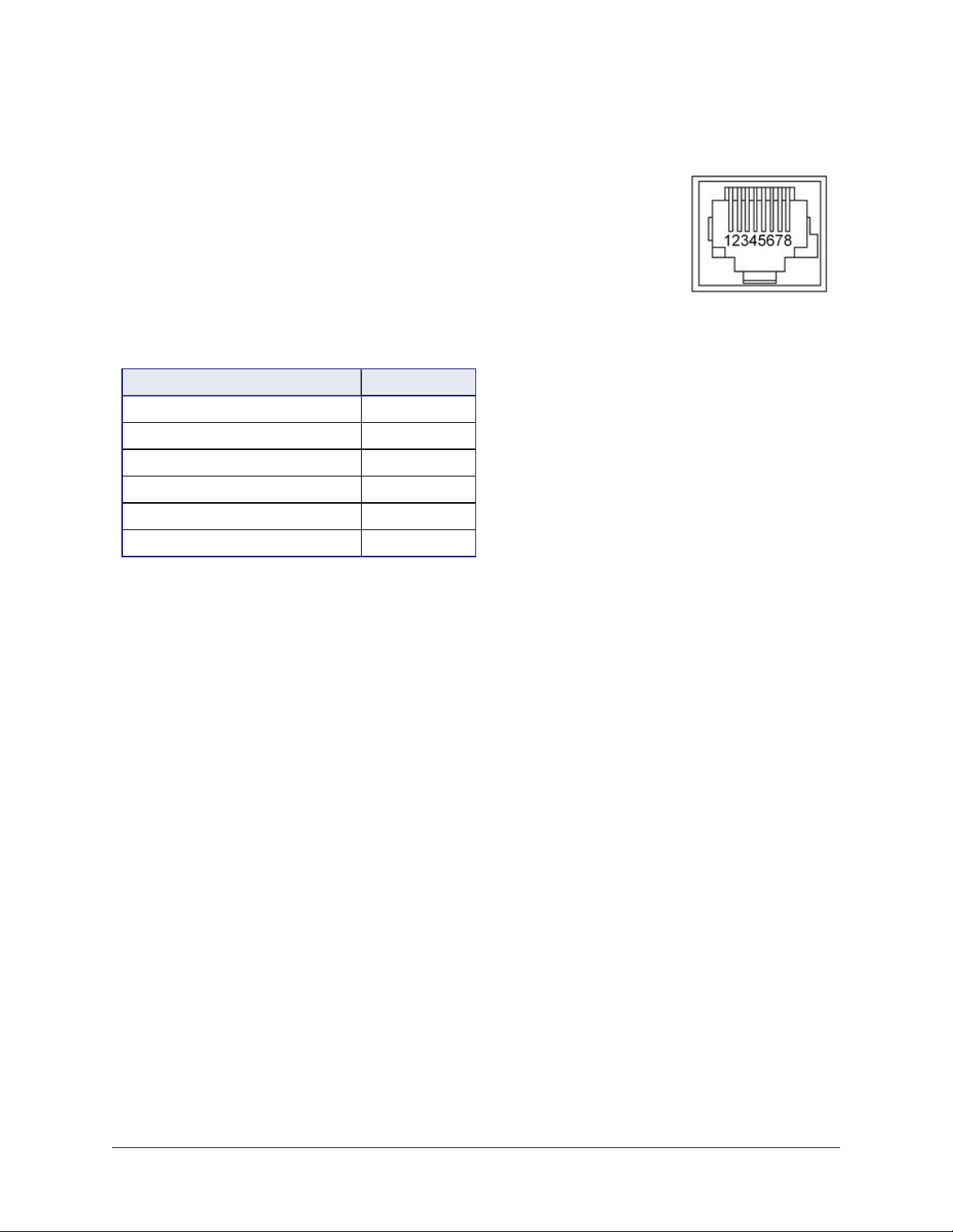
RS-232 Serial Communication Settings and Port Pin-outs
The RS-232 serial port (color-coded blue) on the back panel connects to a third-party controller.
RS-232 connector pin-out:
n Pin 1: Not used
n Pin 2: Not used
n Pin 3: Not used
n Pin 4: Not used
n Pin 5: Not used
n Pin 6: GND
n Pin 7: TXD (to RXD of camera)
n Pin 8: RXD (from TXD of camera)
Communication parameters:
Parameter Value
Communication Speed 38400 bps
Start bits 1
Stop bits 1
Data bits 8
Parity None
Flow control None
Caution
Check your cables. Connecting a cable to the wrong port or using the wrong pin-out can result in equipment
damage and will void the warranty
Depending on the equipment connected to the RS-232 port, you may need a null-modem (crossover) cable.
Powering Up
Power up the AV Bridge Mini and the connected equipment at the same time, or power up the connected
equipment before you power up the AV Bridge Mini.
6
Page 10

Complete Manual for the AV Bridge Mini HD Audio/VideoEncoder
Web Interface
The HD audio/video encoder provides a web interface to allow configuration via the IP network connection,
using a browser. The web interface allows you to:
n Set idle session behavior and passwords
n Manage network and streaming settings
n Add identifying information to the web interface
n Back up, reboot, reset, or update the device
n View information about the device's firmware and current settings
You can access the web interface either through the network or from a computer connected directly to the
network port.
When connected to a LAN that has a DHCP server, the HD audio/video encoder will get its IP address,
gateway and routing information automatically and you will be able to browse to it. In the absence of a
DHCP server, the device's default IP address is 169.254.1.1 and its subnet mask is 255.255.0.0.
If the LAN does not have a DHCP server, you will need to configure the device for your network, as it may
default to the same IP address as other devices.
Getting the Device's IP Address
To see the AV Bridge Mini's current IP address, press the IP button on the front panel. The IP address and
other network information is displayed on the USB and IP streams. Access the USB stream from the
connected computer.
Compatible Web Browsers
Supported web browsers:
n Chrome®
n Firefox®
n Microsoft® Internet Explorer®
n Safari®
Other browsers may also work.
7
Page 11
Complete Manual for the AV Bridge Mini HD Audio/VideoEncoder
User Access
You can access the web interface using the device's IP address. If your network supports hostname
resolution, you can configure the device with an easy-to-remember hostname and access the web interface
using the hostname instead of the IP address.
Note
Only the operator's page is available with user or guest access.
Enter the IP address or hostname in your browser's address bar. (See Getting the Device's IP Address if
you do not already know it.) If you use the hostname, you may need to enter http:// as a prefix to keep
the browser from treating it as a search query.
If the system is configured for guest access, you will not need to log in.
If a login is required, the username is user. Contact the system administrator if you do not know the
current password.
8
Page 12
Complete Manual for the AV Bridge Mini HD Audio/VideoEncoder
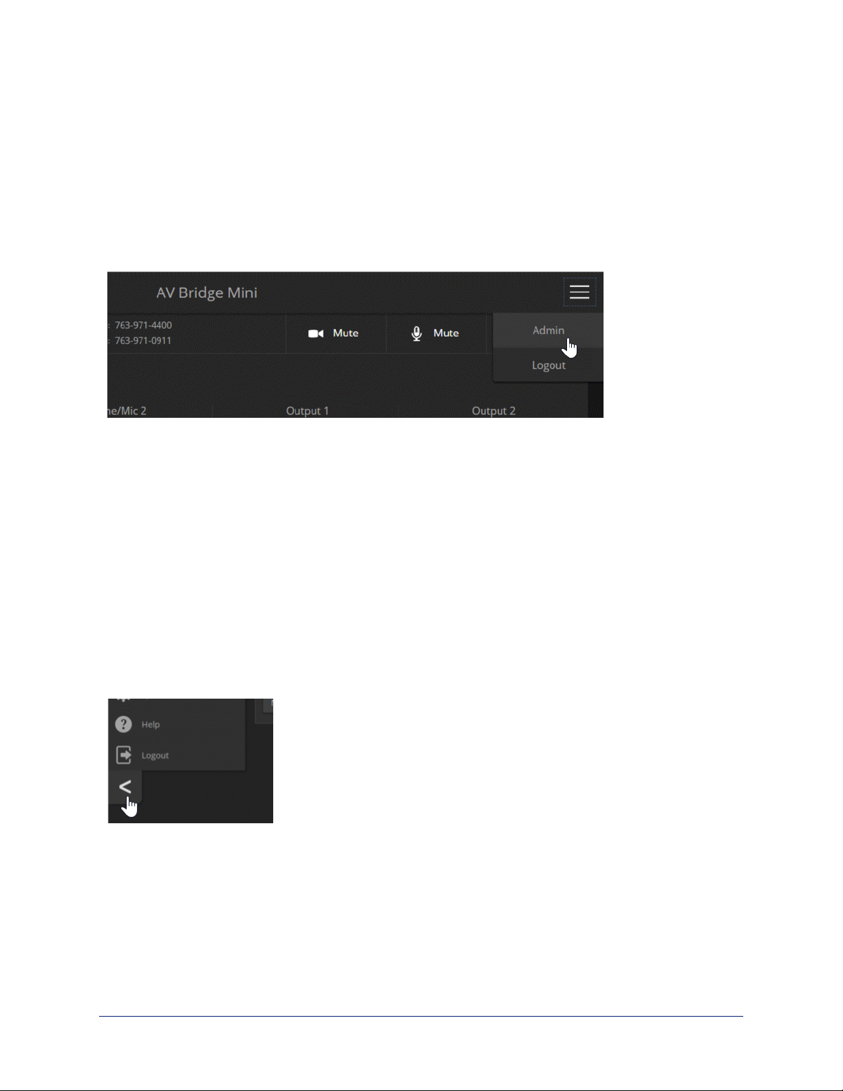
Admin Access
If no administrative controls (such as networking, security, or system pages) are available, you’re logged in
at the user level, or guest access is enabled and you’re not logged in at all.
Use the menu access button to select the admin login. The default password is password. The admin has
access to all pages of the web interface.
Note
For best security, Vaddio strongly recommends changing the default password(s). Using default
passwords leaves the product vulnerable to tampering. See Managing Access and Passwords.
The admin account has access to system administration tasks and performance/behavior configuration
tasks.
System administration tasks are on the following pages, listed in the lower portion of the left navigation
panel:
n Networking page– Configure date and time settings, hostname, and IP addressing
n Room Labels page – Information to display on the web interface screens, including the conference
room name and phone number and the in-house number for AV assistance.
n Help page– Tech support contact information and a link to the product information library on the Vaddio
website.
n Diagnostics page– View or download logs when troubleshooting issues.
n Logout button– A graceful way to leave the web interface in a password-protected state.
Performance and behavior configuration tasks are on the following pages, listed in the upper portion of the
left navigation panel:
n Audio page– Configure and adjust audio inputs and outputs; configure the audio matrix
n Streaming page– Configure USBand IP streaming
Compact Menu View
By default, the navigation buttons display an icon and a text label. The web
interface provides a compact view of the menu buttons along with the default
view. The button at the bottom of the menu toggles between the two views.
9
Page 13

Complete Manual for the AV Bridge Mini HD Audio/VideoEncoder
Web Interface Cheat Sheets
Where to find the controls you need right now.
With admin access:
What do you need? Go to this page
Global audio mute/unmute Available from any page
All other audio functions Audio
Global video mute/unmute Available from any page
IP streaming and USB streaming settings Streaming
Passwords for admin and user accounts; guest access; Telnet access Security
Enable/disable session timeout Security
Hostname and network settings Networking
Time and date settings Networking
Reboot or factory reset System
Backup and restore operations System
Firmware update and current version System
Helpdesk phone number for end users Room Labels
Contact information for Vaddio helpdesk Help
Diagnostic log Diagnostics
Information about the device's location Room Labels
Standby Available from any page
Logout Available from any page
10
Page 14

Complete Manual for the AV Bridge Mini HD Audio/VideoEncoder
System Administration Tasks
Administrative tasks are on these pages of the web interface, shown in the lower
portion of the left navigation panel:
n Networking – Network configuration, time zone and NTP server
n Security – Passwords, guest access, other IT security-related settings
n Room Labels – Helpful information to display in the web interface
n System – Controls to reboot, export and import configuration data, and run
firmware updates
n Help – Contact information for Technical Support and a link to the
documentation for this product
n Diagnostics – Logs to help Technical Support troubleshoot issues
Note
Typically, you do not need to configure the device to work with connected Vaddio
products; this is done automatically.
For Non-DHCP Environments: Configuring the Device with a Static IP
Address for Initial Installation
NETWORKING PAGE
Caution
Consult your IT department before editing network settings. Errors in network configuration can make the
device inaccessible from the network. Do not change DHCP/Static addressing, IP address, subnet mask,
or gateway unless you are very familiar with the characteristics and configuration of the network where you
install the device.
By default, the device is set to DHCP and you do not need to configure it with a static IP address.
However, if no DHCP server is available to automatically assign an address, the device will use the default
IP address of 169.254.1.1. Other devices may default to the same IP address. If this is the case, you may
need to follow this procedure.
If you install more than one device on a network that does not automatically assign IP addresses (a nonDHCP network), follow this procedure to prevent IP address conflicts.
Note
If the device is currently at an IP address other than 169.254.1.1, skip this section unless you are
instructed to configure it with a static IP address.
11
Page 15
Complete Manual for the AV Bridge Mini HD Audio/VideoEncoder
To access the device's Networking page during installation (skip this procedure if the device has
already been in service on this network):
1. Connect the device according to the connection diagram, but do not connect it to the network.
2. Connect the network port on the device to the network port on a computer. You may need a crossover
cable.
3. Open a browser and access the device's web interface at http://169.254.1.1.
4. Log in as admin. The default password is password.
5. Navigate to the Networking page.
12
Page 16
Complete Manual for the AV Bridge Mini HD Audio/VideoEncoder
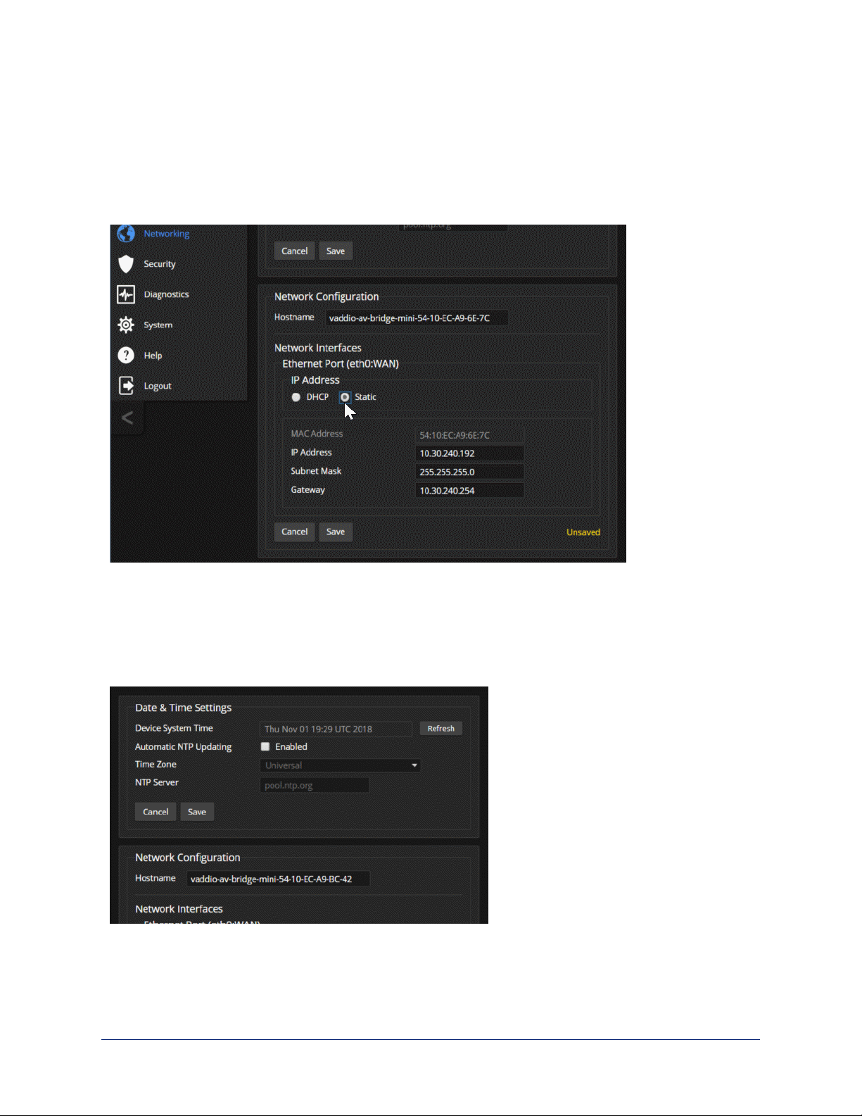
To configure the device with a specific static IP address:
1. Work with your IT department to determine the correct IP address, subnet mask, and gateway to
assign.
2. On the Networking page, set IP Address to Static.
3. Enter the IP address, subnet mask, and gateway as directed by the IT staffer; then save your work.
The device is now ready to be connected to the network.
Changing the Device's Hostname
NETWORKING PAGE
If your network supports hostname resolution, you may find it convenient to change the device's hostname
to something easy to remember. Work with your IT department to ensure that the new hostname conforms
to the organization's naming conventions.
13
Page 17
Complete Manual for the AV Bridge Mini HD Audio/VideoEncoder
Optional For DHCP Environments:Changing from a DHCP Address to a
Static IP Address
NETWORKING PAGE
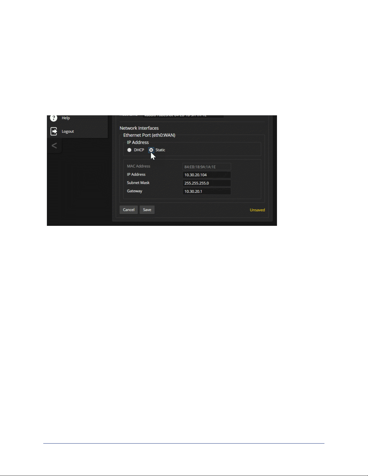
In a network that assigns IP addresses automatically, the device's IP address may change from time to
time. To keep this from happening, set the IP address to Static after the device has received an IP address.
Do not change the IP address, subnet mask, or gateway.
You may wish to change the IP addresses of other connected equipment to static addresses as well. For
all Vaddio products with web interfaces, this setting is on the Networking page.
14
Page 18
Complete Manual for the AV Bridge Mini HD Audio/VideoEncoder
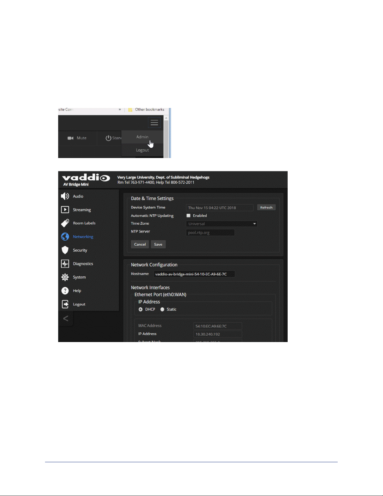
Setting System Time and Time Zone
NETWORKING PAGE
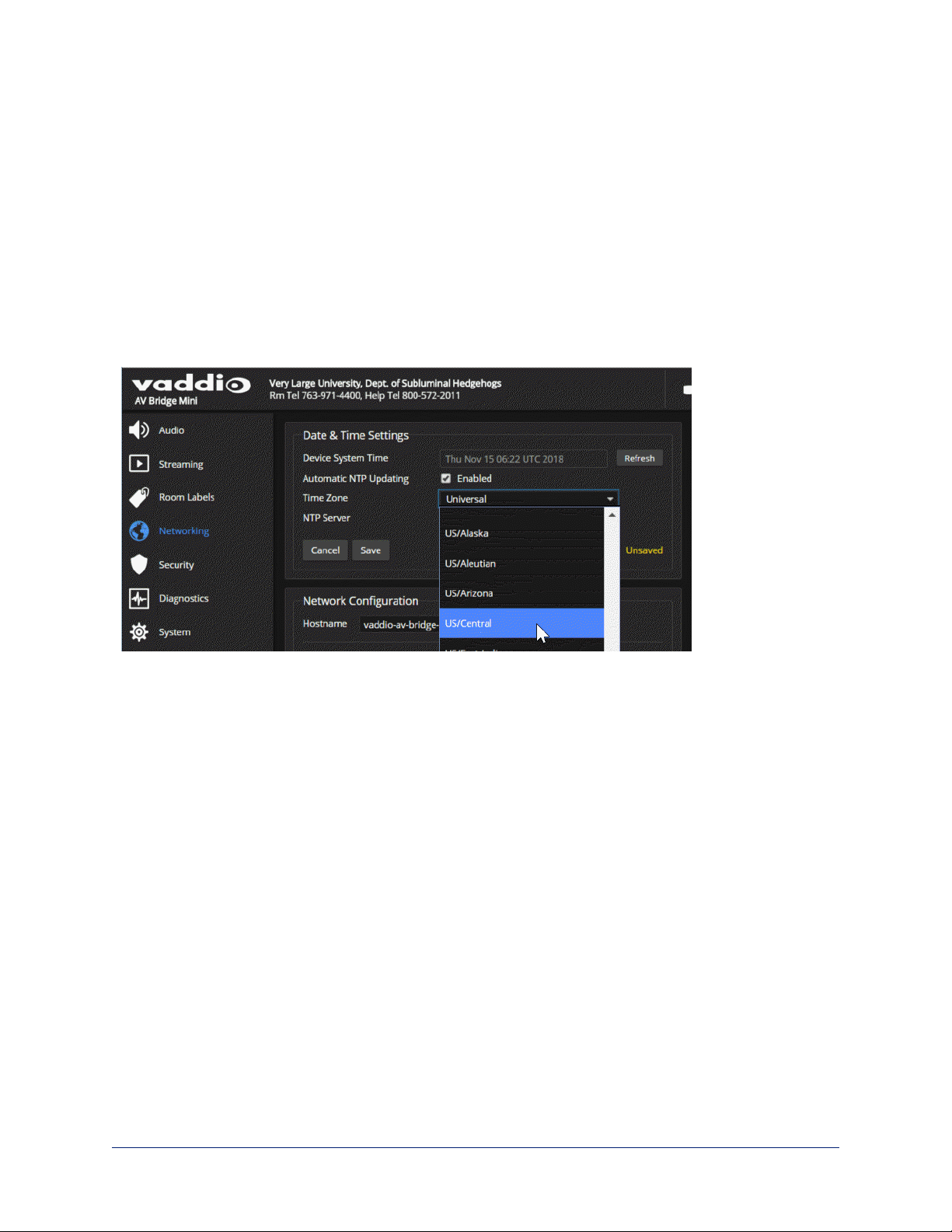
Using automatic NTP updating ensures that the timestamps in the device's diagnostic log are accurate.
Specifying your time zone may make it easier to match logged events with other actions and external
events.
1. To make the time zone and NTP server editable, enable Automatic NTP Updating.
2. Select the desired time zone from the list.
3. Optional: Specify the NTP server to use. If you are not sure about this, use the default.
4. Save your changes.
5. To update the system time immediately, select Refresh. Otherwise, the time will update the next time
the device contacts the NTP server.
15
Page 19
Complete Manual for the AV Bridge Mini HD Audio/VideoEncoder
Managing Access and Passwords
SECURITY PAGE
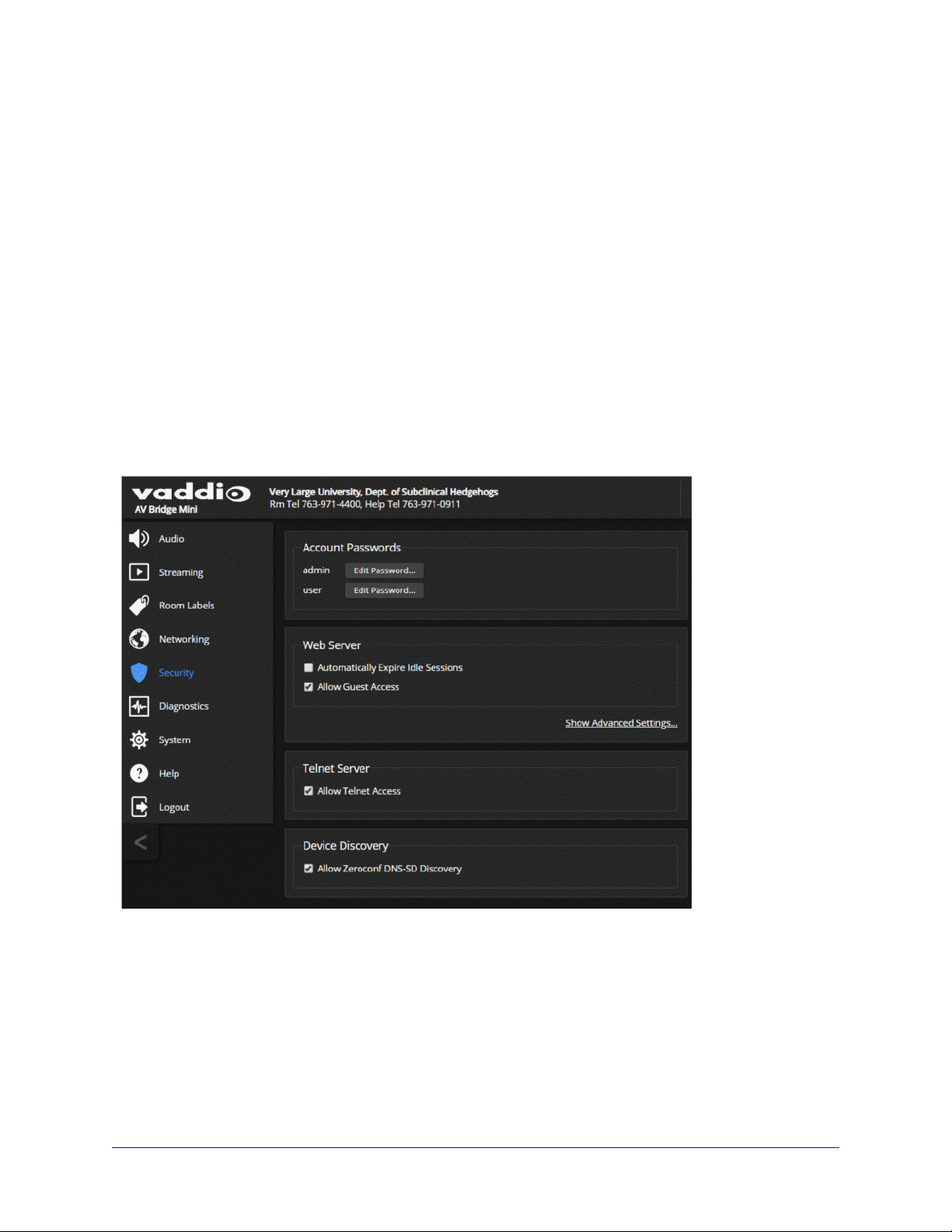
You can set up the appropriate level of security to conform to your organization's requirements.
Note
Consult your network security specialist before changing any of these settings.
Change a password – Select Edit Password for the appropriate account (user or admin) to open the Edit
Password dialog box.
Idle session time-out – check the box labeled Automatically Expire Idle Sessions to automatically log you
out of the web interface after 30 minutes without interaction.
Require a password for user access – clear the box labeled Allow Guest Access. (A password is always
required for administrative access via the web interface or a Telnet session.)
Disable Telnet access – clear the box labeled Telnet Server Enabled.
Note
For best security, Vaddio strongly recommends changing the user and admin passwords. Using
the default passwords leaves the product vulnerable to tampering.
16
Page 20

Complete Manual for the AV Bridge Mini HD Audio/VideoEncoder
Enabling or Requiring HTTPS
SECURITY PAGE
By default, the web interface uses the HTTP protocol. You can configure the web interface to require a
secure HTTPS connection instead.
Caution
Work with your network security professional to manage the device's SSL certificate. Do not make any
changes in the Certificate or Private Key text boxes without guidance from your organization's network
security professional.
The settings in this section are under Advanced Settings.
To switch to a secure HTTPS connection for the remainder of your session:
Select Switch to HTTPS.
Note
If the device is configured for HTTPS access but no SSL certificate is installed, your browser may present
messages warning you that your connection is not secure, because the site's certificate is not valid.
17
Page 21

Complete Manual for the AV Bridge Mini HD Audio/VideoEncoder
To require HTTPS connections:
Clear the box labeled HTTP Access Enabled. The device's web interface will only be available via an
HTTPS connection.
Adding Room Information
ROOM LABELS PAGE
Enter information about the location of the equipment and the local IT or A/V help line. This information will
be displayed on all pages of the web interface.
18
Page 22

Complete Manual for the AV Bridge Mini HD Audio/VideoEncoder
Rebooting
SYSTEM PAGE
This can help if the device stops responding as you expect.
In the System Utilities section, select Reboot, then confirm. You will need to log in again after the reboot.
If rebooting the device doesn't fix the problem, you may need to restore factory defaults. But before you
take that step, back up the configuration.
19
Page 23

Complete Manual for the AV Bridge Mini HD Audio/VideoEncoder
Exporting and Importing Configuration Data
SYSTEM PAGE
If your organization uses several of the same product, you may choose to configure one of them, verify that
the configuration is good, and then copy it to the others. Most Vaddio professional AV products and
cameras have this capability.
20
Page 24

Complete Manual for the AV Bridge Mini HD Audio/VideoEncoder
To export a configuration:
To save a copy of the current configuration, select Export Data.
The configuration exports as a .dat file and downloads to your default file download location. The filename
is the device's hostname followed by the .dat file extension. If you only need to back up the configuration,
you're done.
Note
This operation does not copy device-specific data such as hostname or sensitive data such as passwords.
To import a configuration:
1. Select Import. The Import Data box opens.
2. Select Choose File, and browse to the .dat file to be imported.
3. Select Begin Importing Data. When the import is complete, the device reboots and you will need to log
in again.
21
Page 25

Complete Manual for the AV Bridge Mini HD Audio/VideoEncoder
Updating the Firmware
From time to time, we issue new firmware to introduce new features and other product improvements, and
to fix issues that turn up. We recommend keeping all your Vaddio products up to date, to get the most out of
them.
Firmware updates do not change the configuration or password.
Note
It is rare for an update to generate errors. If this happens, please read them carefully and record them.
Screen shots of the error message may be very helpful in troubleshooting the problem. If the update does
not finish successfully, contact Vaddio technical support immediately.
1. In a separate browser tab or window, go to the appropriate product page, or to the software updates
section of support.vaddio.com and download the appropriate update file.
2. In the Firmware Update pane, select Choose File. Then browse to the update file and select it.
3. Select Begin Firmware Update.
4. READ the information in the Confirm dialog box and be sure you understand it.
5. When you are ready to start the update, select Continue. The device reboots as the last step in the
update process.
22
Page 26

Complete Manual for the AV Bridge Mini HD Audio/VideoEncoder
Contacting Vaddio Technical Support
HELP PAGE
If you can't resolve an issue using your troubleshooting skills (or the Troubleshooting table in this manual),
we are here to help. You'll find technical support contact information on the Help page. Each product
displays a different link, to provide direct access to the product information.
Viewing Diagnostic Logs
DIAGNOSTICS PAGE
If you encounter a problem that you can’t solve, your Vaddio technical support representative may ask you
to download and email the log file available from the Diagnostics screen.
23
Page 27

Complete Manual for the AV Bridge Mini HD Audio/VideoEncoder
Performance and Behavior Settings
Performance and behavior settings for the AV Bridge Mini HD audio/video encoder are on these pages of
the web interface, shown in the upper portion of the left navigation panel:
n Audio – Adjusting audio inputs and outputs; configuring the audio matrix
n Streaming – Configuring USB streaming and IP streaming
Configuring Audio Settings
AUDIO PAGE (MULTIPLE TABS)
The web interface provides separate controls for each of the audio inputs and
outputs:
n Analog – Line/Mic inputs 1 and 2 (typically the room's microphones) ; audio line out 1 and 2 (typically the
room's speakers)
n Digital – Near-end and far-end audio for the USB stream and the IP stream
n Matrix – defines audio routing
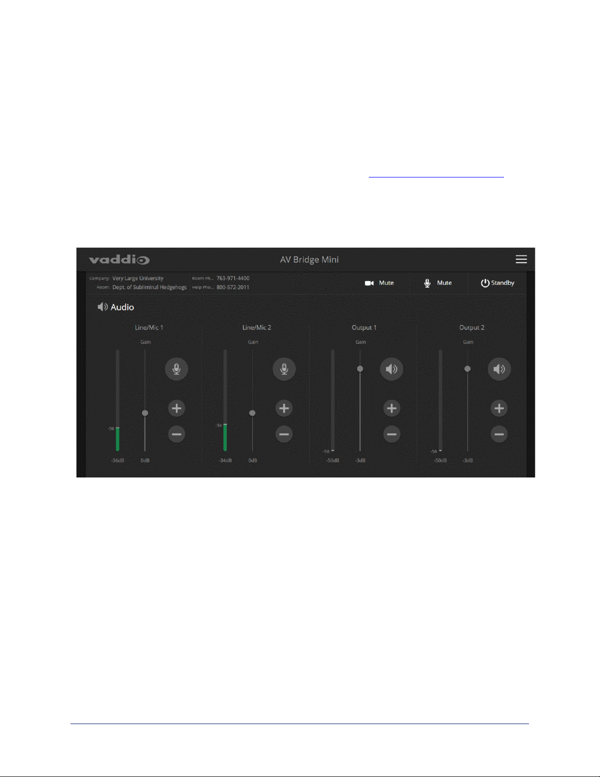
Muting and Setting Volume
AUDIO PAGE, ANALOG AND DIGITAL TABS
To mute all audio:
Use the microphone mute control at the top of any page.
To mute a specific audio input or output:
Click the icon button (microphone or speaker) associated with the input or output.
To change the volume of a specific audio input or output:
Move the volume slider associated with the input or output.
Note
For best performance with most computers, we recommend setting the USB Record volume high.
24
Page 28

Complete Manual for the AV Bridge Mini HD Audio/VideoEncoder
Microphone Adjustments
AUDIO PAGE, ANALOG TAB
To adjust for more natural speech reproduction:
n High-pass filter – Specify the lowest frequency that the microphone should pick up. Use this setting to
reduce low-frequency background noise such as heating/air conditioning systems.
n Low-pass filter – Specify the highest frequency that the microphone should pick up. Use this setting to
reduce hissing sounds and make speech sound natural.
n Automatic Gain Control – Check the box to adjust gain automatically to compensate for differences
in volume as different people speak.
Speaker Adjustments
AUDIO PAGE, ANALOG TAB
To compensate for differing speech volumes:
If some people on the far end are inaudible while others are too loud, check the Compressor box to reduce
the dynamic range from the connected speakers.
To compensate for specific audio issues on the far end:
Use the equalizers for the analog outputs to attenuate specific frequency ranges. This can help if the farend audio includes unwanted elements such as a rumbling HVAC system or a cricket in the room.
25
Page 29

Complete Manual for the AV Bridge Mini HD Audio/VideoEncoder
Synchronizing Audio with Video in the IP Stream
AUDIO PAGE, DIGITAL TAB
If the video lags noticeably behind the audio in the IP stream, check the Delay box for the appropriate audio
outputs and enter a delay value in milliseconds. The delay may differ from one output to the other.
26
Page 30

Complete Manual for the AV Bridge Mini HD Audio/VideoEncoder
Routing Audio
AUDIO PAGE, MATRIX TAB
The audio matrix defines where each audio output originates. Each column of the matrix shows one audio
output, and each row shows one audio input. Table cells highlighted in blue mean that the input represented
in that row is routed to the output represented in that column.
To specify how the AV Bridge Mini uses a given audio input, locate its row. Locate the column representing
the desired output and select the table cell where the desired row and column intersect.
Example: In the screen shot below...
n The microphone or other audio source connected to Mic/Line In 1 provides the left-channel audio in both
the USB and IP streams.
n The microphone or other audio source connected to Mic/Line In 2 provides the right-channel audio in
both the USB and IP streams.
n The USB stream and the IP stream both send the left channel of far-end audio to the speaker connected
to Line Out 1, and right channel to the speaker connected to Line Out 2. Depending on how the audio is
configured at the far end, people in the room may hear the far end in stereo.
27
Page 31

Complete Manual for the AV Bridge Mini HD Audio/VideoEncoder
Setting Gain Between Input and Output (Crosspoint Gain)
To adjust crosspoint gain between any input and the output to which it is routed, right-click the table cell in
the matrix to open a gain control.
28
Page 32

Complete Manual for the AV Bridge Mini HD Audio/VideoEncoder
Configuring Streaming Settings
STREAMING PAGE
USB streaming cannot be disabled. IP streaming is disabled by default.
Supported Input Resolutions and Frame Rates
The AV Bridge Mini accepts the following resolutions and frame rates from the connected camera or other
video input device:
n 3840x2160p at 30 fps
n 1920x1080p at 60, 59.94, 50, and 30 fps
n 1920x1080i at 60, 59.94, and 50 fps
n 1280x720p at 60, 59.94, and 50 fps
n 1440x900 at 60 fps
n 1280x800 at 60 fps
Configuring USB Streaming
STREAMING PAGE
To change the USB device name:
Edit the USB Device Name to change the way the AV Bridge Mini shows up in your soft client's device
selection list.
To allow soft client control of the audio:
Check the Enabled box for HID Audio Controls to allow conferencing applications to control the audio.
Note
Most USB streaming settings are automatically negotiated with the conferencing application.
29
Page 33

Complete Manual for the AV Bridge Mini HD Audio/VideoEncoder
Set IP Streaming Video Settings
STREAMING PAGE
If you are not sure how to configure streaming settings, start with the Easy mode defaults. This configures
most settings automatically.
To set up IP streaming in Easy quality mode:
1. Select Easy quality mode.
2. Select the desired IP streaming resolution. This determines the size of the window in which the stream
is displayed.
3. Easy quality mode only: Select Video Quality.
4. Save your changes.
Pro Tip
If streaming video quality is poor, try a lower resolution or bandwidth.
30
Page 34

Complete Manual for the AV Bridge Mini HD Audio/VideoEncoder
To set up IP streaming in Custom quality mode:
1. Select Custom quality mode.
2. Select the desired resolution.
3. Select the desired IP streaming frame rate.
4. Select Constant or Variable bit rate.
5. Constant bit rate only: Set Max Bandwidth.
6. Variable bit rate only: Set the Quality (Quantization) slider.
7. Save your changes.
31
Page 35

Complete Manual for the AV Bridge Mini HD Audio/VideoEncoder
RTSP Streaming Settings
STREAMING PAGE
RTSP port: Vaddio strongly recommends using the default RTSP port number.
Path: The portion of the streaming URL that appears after the IP address. You may wish to change this to
help identify the stream source – for example, demo-studio-3.
URL: The location where the stream can be viewed. This will change if you edit the path.
To view the RTSP stream:
1. Open a stream viewer such as VLC Media Player.
2. Select "Network stream" or your viewer's equivalent option.
3. Copy the streaming URL from the device's Streaming page and paste it into the viewer as the URL for
the network stream.
32
Page 36

Complete Manual for the AV Bridge Mini HD Audio/VideoEncoder
RTMP Streaming Settings
STREAMING PAGE
To use RTMP streaming, you must have an account with a streaming service.
Notes
When RTMP streaming is selected and a content service provider is configured, the device streams to the
service until you stop the stream. Configure RTMP streaming before enabling it.
The RTMP stream can only be viewed from the content service provider. No local display or preview is
available.
To configure an RTMP streaming service:
1. Select RTMP streaming, then select Settings.
2. Expand the information box for the service.
3. Enter the name of the service.
4. Paste in the key and URL(s) provided by the service.
33
Page 37

Complete Manual for the AV Bridge Mini HD Audio/VideoEncoder
To select the enabled RTMP streaming service:
Expand the list of available streaming services, and select the one to use.
Enable IP streaming when you are ready to start sending content to the streaming service.
Stopping the IP Stream
STREAMING PAGE
Just as a camera outputs video unless you mute it or put it in standby, the AV Bridge Mini streams audio
and video unless you take action to stop the stream.
Options:
n To stop IPstreaming entirely: Clear the Enable IP Streaming check box.
n To stop the video portion of the stream, but leave the stream running: Mute the video. Audio
remains available.
n To stop the audio portion of the stream, but leave the stream running: Mute the audio. Video
continues to stream.
n To stop sending the stream to a content service provider but make it available as a network
stream: Change from RTMP to RTSP streaming. Local video is still displayed on the connected screen
(s).
n To stop all streaming: Put the AV Bridge Mini in standby mode. All AV Bridge Mini functions stop.
Advanced: Changing MTU
STREAMING PAGE
The default packet size for streaming is 1400. Do not change this except in consultation with your network
administrator.
34
Page 38

Complete Manual for the AV Bridge Mini HD Audio/VideoEncoder
Customizing Labels
Some of the labels in the web interface are customizable – because you may find, for example, that
"Podium" is a more useful label than "Line/Mic 1."
When in doubt, try it.
Right-click the label you want to rename. If it is customizable, it opens a dialog box.
35
Page 39

Complete Manual for the AV Bridge Mini HD Audio/VideoEncoder
Serial Command API
The Vaddio serial command API allows an external device such as an AMX or Crestron presentation
system to control the device. It is also used for device macros. The serial command API can be accessed
via Telnet or direct RS-232 connection. Commands are the same using either communication protocol.
Note
When you connect via Telnet, you must log in using the admin account.
Things to know about Telnet:
n Telnet port 23 is used.
n The > character is the command prompt.
n Using a question mark as a command or command parameter will bring up a list of available
commands, subcommands, or command parameters. For example, ? returns all top-level commands;
system ? returns the valid subcommands for the system command; and system reboot ? returns
the parameter available for the system reboot command.
n CTRL-5 clears the current serial buffer on the device.
Typographical conventions:
n n {x | y | z} – Choose x, y, or z.
n n <variable> – The named variable (such as <ip address>)is required.
n n < x..y > – Avalue in the range of x through y is required.
n n [optional] – This parameter (such as [speed <1..7>]) is not required.
For information about the RS-232 serial interface, see RS-232 Serial Communication Settings and Port
Pin-out.
36
Page 40

Complete Manual for the AV Bridge Mini HD Audio/VideoEncoder
audio volume
Gets or sets the volume of the specified audio channel. The valid range depends on the channel.
Synopsis audio [channel ] volume {get | up | down | set <level> }
Channels
Options
Examples
master
line_in_1
line_in_2
usb3_playback_left
usb3_playback_right
hdmi_in_left
hdmi_in_right
line_out_1
line_out_2
usb3_record_left
usb3_record_right
ip_out_left
ip_out_right
get
up
down
set <level>
audio line_in_1 volume up
OK
>
Gets or sets the volume of the audio master
control.
Gets or sets the volume of the specified Audio
Line In.
Get or set the volume for the USB3 Playback
Left/Right input channel.
Get or set the volume for the left/right channel of
the specified HDMI input.
Gets or sets the volume of the specified Audio
Line Out.
Get or set the volume for the USB3 Record
Left/Right output channel.
Get or set the volume for the left/right channel of
the IP stream's audio.
Returns the current volume of the specified
channel.
Increases the volume of the specified channel by
1 dB.
Reduces the volume of the specified channel by 1
dB.
Sets the volume of the specified channel in dB.
Valid ranges:
Line in, line out, master/AEC reference: -50.0 to
20.0 dB
USB, IP, and HDMI: -42.0 to 6.0 dB
Increases the volume for Line In 1 by 1 dB.
audio line_out_1 volume get
volume -10.0 dB
OK
>
Returns the current volume for the speaker connected to the line out port.
37
Page 41

Complete Manual for the AV Bridge Mini HD Audio/VideoEncoder
audio mute
Gets or sets the mute status of the specified audio channel.
Synopsis audio <channel> mute {get | on | off | toggle}
Channels
Options
Examples
master
line_in_1
line_in_2
usb3_playback_left
usb3_playback_right
hdmi_in_left
hdmi_in_right
line_out_1
line_out_2
usb3_recond_left
usb3_record_right
ip_out_left
ip_out_right
get
on
off
toggle
> audio master mute get
mute: off
OK
>
Gets or sets the mute status of master audio mute, the
emergency mute for all channels. This is equivalent to
the Mute button on the front panel or in the operator's
web interface.
Gets or sets the mute status of the specified Line In
port.
Gets or sets the mute status of the USB3 Playback
Left/Right channel.
Gets or sets the mute status of the left/right channel of
the HDMI audio input.
Gets or sets the mute status of the specified Line Out
port.
Gets or sets the mute status of the USB3 Record
Left/Right channel.
Gets or sets the mute status of the left/right channel of
the IP stream's audio.
Returns the current mute state of the specified
channel.
Mutes the audio for the specified channel.
Unmutes the audio for the specified channel.
Changes the mute state for the specified channel –
unmutes if it was muted, mutes if it was not.
Returns the current mute state of master mute. It is off, so audio is not globally
muted. Some audio channels may be muted, however.
>audio line_out_1 mute on
OK
>
Mutes the Line Out 1 port.
38
Page 42

Complete Manual for the AV Bridge Mini HD Audio/VideoEncoder
audio route
Gets or sets the input routed to the specified output.
Synopsis audio <channel> route {get | set <inputs>}
Outputs
Options
Inputs
Examples
line_out_1
line_out_2
usb3_record_left
usb3_record_right
Get or set the inputs routed to the specified Line Out
port.
Get or set the inputs routed to the USB3 Record
Left/Right channel. Not permitted to have USB3
Playback Left/Right in its route list.
ip_out_left
ip_out_right
get
set
line_in_1
line_in_2
usb3_playback_left
usb3_playback_right
hdmi_in_left
hdmi_in_right
> audio usb3_record_left route get
[auto_mic_mix ]
OK
>
Get or set the inputs routed to the left/right channel of
the IP stream.
Returns the routing for the specified output.
Sets the routing for the specified output.
Line In 1 or Line In 2
USB Playback Left/Right channel. Not permitted to
be routed to USB Record.
HDMI input, left or right channel
Returns the current source of the left channel of USB3 Record. The auto mic mixer is
currently routed to the left channel of the USB3 Record output.
> audio ip_out_right route set line_in_1
Routes Line Input 1 to the right channel of the outbound IP stream.
39
Page 43

Complete Manual for the AV Bridge Mini HD Audio/VideoEncoder
audio crosspoint-gain
Returns or sets the input routing gain, in dB, for a given output and input.
Synopsis audio <output> crosspoint-gain <input>{get | set <level>}
Outputs
Inputs
Options
Examples
line_out_1
line_out_2
usb3_record_left
usb3_record_right
ip_out_left
ip_out_right
line_in_1
line_in_2
usb3_playback_left
usb3_playback_right
hdmi_in_left
hdmi_in_right
get
Get or set the gain for the specified input routed to
the Line Out port.
Get or set the gain for the specified input routed to
the USB3 Record Left/Right channel.
Get or set the gain for the specified input routed to
the left/right channel of the IP stream.
Line In 1 or Line In 2
USB Playback Left/Right channel.
HDMI input, left or right channel
Returns the routing gain from the specified input to
the specified output.
set <-12.00 .. 12.00> Sets the routing gain from the specified input to
the specified output. Valid range is -12.00 dB to
12.00 dB.
> audio line_out_1 crosspoint-gain hdmi_in_left get
3.95
OK
>
Returns the current gain setting of the crosspoint between Line Output 1 and HDMI
Input Left in dB.
> audio usb3_record_left crosspoint-gain line_in_1 set 6.00
OK
>
Sets the crosspoint gain of USB Record Left and Line In 1 to 6 dB.
40
Page 44

Complete Manual for the AV Bridge Mini HD Audio/VideoEncoder
streaming settings get
Returns current IP and USB streaming settings.
Synopsis streaming settings get
Parameters
Example
IP Custom_Frame_Rate
IP Custom_Resolution
IP Enabled
IP MTU
IP Port
IP Preset_Quality
IP Preset_Resolution
IP Protocol
IP URL
IP Video_Mode
USB Active
USB Device
USB Frame_Rate
USB Resolution
USB Version
IP Custom_Frame_Rate 30
IP Custom_Resolution 720p
IP Enabled true
IP MTU 1400
IP Port 554
IP Preset_Quality High Quality (Best)
IP Preset_Resolution 1080p
IP Protocol RTSP
IP URL vaddio-avbridge-mini-stream
IP Video_Mode preset
USB Active true
USB Device AV Bridge Mini
USB Frame_Rate 30
USB Resolution 1080p
USB Version 3
OK
>
Frame rate selected in Custom quality mode.
Resolution selected in Custom quality mode.
May be true or false. Specifies whether IP
streaming is enabled.
MTU for IP streaming. Default is 1400.
The RTSPport number used for IP streaming. Default
is 554.
Video quality selected in Easy video quality mode.
Resolution selected in Easy video quality mode.
The IP streaming protocol in use (RTSP or RTMP).
The URL where the stream is available.
Video quality mode selected (preset or custom).
Specifies whether USB streaming is active (in a
conference).
The USB device name.
The current frame rate for the USB stream. If the
device is not in a conference (not streaming USB), the
frame rate is 0.
The current resolution for the USB stream. If the
device is not streaming USB (not in a conference), the
resolution is 0x0.
The USB version in use (USB 3).
41
Page 45

Complete Manual for the AV Bridge Mini HD Audio/VideoEncoder
streaming ip enable
Set or change the state of IP streaming.
Synopsis streaming ip enable {get | on | off | toggle}
Parameters
Example
get
on
off
toggle
>streaming ip enable on
> OK
Enables IP streaming.
>streaming ip enable get
enabled:true
> OK
Returns the current state of IP streaming
Enables IP streaming.
Disables IP streaming.
Changes the state of IP streaming (on if it was
off, or off if it was on). streaming ip
enable toggle has the same effect as
selecting the Enable IP Streaming checkbox in
the web interface.
Returns the current state of IP streaming.
network ping
Sends an ICMP ECHO_REQUEST to the specified IP address or hostname.
Synopsis network ping [count <count>] [size <size>] <destination-ip>
Options <count> The number of ECHO_REQUEST packets to
send. Default is five packets.
<size> The size of each ECHO_REQUEST packet.
Default is 56 bytes.
<destination-ip> The IP address where the ECHO_REQUEST
packets will be sent.
Examples
>network ping 192.168.1.66
PING 192.168.1.66 (192.168.1.66): 56 data bytes
64 bytes from 192.168.1.66: seq=0 ttl=64 time=0.476 ms
64 bytes from 192.168.1.66: seq=1 ttl=64 time=0.416 ms
64 bytes from 192.168.1.66: seq=2 ttl=64 time=0.410 ms
64 bytes from 192.168.1.66: seq=3 ttl=64 time=0.410 ms
64 bytes from 192.168.1.66: seq=4 ttl=64 time=3.112 ms
--- 192.168.1.66 ping statistics --5 packets transmitted, 5 packets received, 0% packet loss
round-trip min/avg/max = 0.410/0.964/3.112 ms
>
Sends five ECHO_REQUEST packets of 56 bytes each to the host at
192.168.1.66.
>network ping count 10 size 100 192.168.1.1
Sends 10 ECHO_REQUEST packets of 100 bytes each to the host at 192.168.1.1.
The command returns data in the same form as above.
42
Page 46

Complete Manual for the AV Bridge Mini HD Audio/VideoEncoder
network settings get
Returns the device's current network settings, including MAC addres, IP address, netmask, and gateway.
Synopsis network settings get
Example network settings get
Name: eth0:WAN
MAC Address: 00:04:a3:85:0a:ee
IP Address: 10.10.8.116
Netmask: 255.255.255.0
VLAN: Disabled
Gateway: 10.10.8.100
OK
>
system reboot
Reboots the system either immediately or after the specified delay. Note that a reboot is required when
resetting the system to factory defaults (system factory-reset).
Synopsis system reboot [<seconds>]
Options <seconds> The number of seconds to delay the reboot.
Examples
>system reboot
OK
>
The system is going down for reboot NOW! avbmini-D8-80-39-62-A7-C5
Reboots the system immediately.
>system reboot 30
Reboots the system in 30 seconds. The response is in the same form; the system
message appears at the end of the delay.
43
Page 47

Complete Manual for the AV Bridge Mini HD Audio/VideoEncoder
system factory-reset
Gets or sets the factory reset status. When the factory reset status is on, the system resets to factory
defaults on reboot.
Synopsis system factory-reset {get | on | off}
Options
Examples
get
Returns the device's current factory reset
status.
on
off
>system factory-reset get
factory-reset (software): off
factory-reset (hardware): off
OK
>
Enables factory reset on reboot.
Disables factory reset on reboot.
Returns the factory reset status.
This evaluates the most recent system factory-reset on or off command, if
one has been received, then reads the rear panel DIP switches and returns the
status on if they are all in the down position.
>system factory-reset on
factory-reset (software): on
factory-reset (hardware): off
OK
>
Enables factory reset upon reboot.
Note
This command does not initiate a factory reset. The factory reset takes place on the
next reboot.
version
Returns the current firmware version.
Synopsis version
Example
version
Returns current firmware version information in a form something like
this:
Audio 1.05
Commit 418875905f5f27cf01f83c16686df348f2f7ebb9
System Version AV Bridge Mini 1.0.0
USB 01.01.003
OK
>
44
Page 48

Complete Manual for the AV Bridge Mini HD Audio/VideoEncoder
history
Returns the most recently issued commands from the current Telnet session. Since many of the programs
read user input a line at a time, the command history is used to keep track of these lines and recall historic
information.
Synopsis history <limit>
Options
Examples
Additional information You can navigate the command history using the up and down arrow
<limit>
history
Displays the current command buffer.
history 5
Sets the history command buffer to remember the last 5 unique entries.
keys.
This command supports the expansion functionality from which previous
commands can be recalled from within a single session. History
expansion is performed immediately after a complete line is read.
Examples of history expansion:
* !! Substitute the last command line.
* !4 Substitute the 4th command line (absolute as per ’history’
command)
* !-3 Substitute the command line entered 3 lines before (relative)
Integer value specifying the
maximum number of commands to
return.
help
Displays an overview of the CLI syntax.
Synopsis help
Example
Note
Use ? as a command parameter to see information about a given command's syntax.
help
exit
Ends the command session. If the session is via Telnet, the Telnet socket closes as the session ends. If
the session is via RS-232 serial connection, the session ends and a new session automatically opens.
Synopsis exit
Example
exit
45
Page 49

Complete Manual for the AV Bridge Mini HD Audio/VideoEncoder
Specifications
USB Stream Video and Audio; Up to 1080p/60 Resolution (Full HD)
IP Stream RTSP or RTMP Video and Audio; Up to 1080p/30 Resolution
HDMI Input Video and Audio; Up to 2160p/30 Resolution (UHD)
Audio Inputs Stereo USB
Stereo HDMI
Two Balanced Mic/LineLevel Inputs
Audio Outputs Stereo USB
AAC IP Audio Stream
Two Balanced Line-Level
Outputs
Control Browser-based user interface for configuration and administration; front panel
controls for IP address toggle, power reset, and factory reset; Telnet and RS232 for external control
Input Power PoE Phantom Power to
Microphones
Height
Depth
1.72 in. (4.4 cm)
6.0 in. (15.2 cm)
Width
Weight
48 VDC, 10 mA
8.38 in. (21.3 cm)
2.65 lb. (1.2 kg, or 1273
plain M&M candies)
Temperature Operating and Storage: 32° to 104° F (0° to 40° C)
Humidity Operating and Storage:20% to 80% RH non-condensing
46
Page 50

Complete Manual for the AV Bridge Mini HD Audio/VideoEncoder
Troubleshooting and Care
If the equipment does not behave as you expect, use this table to determine whether to call Vaddio
Technical Support.
Note
If the equipment behaves in a way that suggests even a remote possibility of a bad cable, please try a
known good cable with the same pin-out. Factory-made cables can be defective. Cables can appear to be
good but only work part of the time. A cable may pass a standard continuity check but be unable to pass
enough power to the connected device.
Crimping tools can crimp unevenly, contacts can break internally, and individual conductors in the cable
can break inside the jacketing material. Any of these can result in a cable that passes a continuity check
but does not work reliably.
(The author would like to confess having made more than a few almost-good cables. It happens.)
Power Issues
What is it doing? Possible causes Check and correct
Nothing. The buttons do not
light up.
At least one microphone does
not work.
Power is not connected. Check the connections from the wall
outlet to the PoE+ power injector and
from the power injector to the device.
The wall outlet is not active.
(Check by finding out if it
powers something else, such
as a laptop or phone charger.)
The device or its power injector
is bad.
Microphone requires phantom
power, which is not enabled.
Use a different outlet.
Contact your reseller or Vaddio
Technical Support.
Enable phantom power for the affected
microphone. (Web interface, Audio
page)
47
Page 51

Complete Manual for the AV Bridge Mini HD Audio/VideoEncoder
Network and Communication Issues
What is it doing? Possible causes Check and correct
Unable to access the web
interface.
The device is not connected to
the network.
Check to be sure the PoE injector's
network cable is connected.
Check using a known good cable.
The device is not at the IP
address you browsed to.
Follow the procedure for Getting the
Device's IP Address. If it is
169.254.1.1, the device needs to be
configured for your network. See
Configuring the Device for Your
Network.
Unable to log in successfully. The web interface is out of
Use the browser's page refresh button.
sync with the unit. This can
happen if more than one person
is controlling the device.
The password has been
changed.
Contact your system administrator. If
you are the system administrator, call
Vaddio Technical Support.
Restoring Factory Defaults
SYSTEM PAGE
To restore the original factory settings:
Select Restore Factory Settings.
A confirmation message informs you that the action cannot be undone. This is your cue to make sure you
have successfully exported the configuration.
This operation logs you out and resets the admin password to its factory default value of password.
Operation, Storage, and Care
For smears or smudges on the product, wipe with a clean, soft cloth. Do not use any abrasive chemicals.
Keep this device away from food and liquids.
Do not operate or store the device under any of the following conditions:
n Temperatures above 40°C (104°F) or below 0°C (32°F)
n High humidity, condensing or wet environments
n Inclement weather
n Severe vibration
n Dry environments with an excess of static discharge
n While exiting, pursued by a bear
Do not attempt to take this product apart. There are no user-serviceable components inside.
48
Page 52

Complete Manual for the AV Bridge Mini HD Audio/VideoEncoder
Compliance Statements and Declarations of Conformity
Compliance testing was performed to the following regulations:
FCC Part 15 (15.107, 15.109), Subpart B Class A
ICES-003, Issue 54: 2012 Class A
EMC Directive 2014/30/EU Class A
EN 55032: 2015 Class A
EN 55024: November 2010 Class A
KN24 2008 (CISPR 24: 1997 + A1: 2000 + A2: 2002) Class A
IEC 60950-1:2005 (2nd Edition); Am 1: 2009 + Am 2: 2013 Safety
EN 60950-1: 2006 + A11: 2009 + A1: 2010 + A12: 2011 + A2: 2013 Safety
FCC Part 15 Compliance
This equipment has been tested and found to comply with the limits for a Class A digital device, pursuant to
Part 15, Subpart B, of the FCC Rules. These limits are designed to provide reasonable protection against
harmful interference when the equipment is operated in a commercial environment. This equipment
generates, uses, and can radiate radio frequency energy and, if not installed and used in accordance with
the instruction manual, may cause harmful interference to radio communications. Operation of this
equipment in a residential area is likely to cause harmful interference in which case the user will be required
to correct the interference at his/her own expense.
Operation is subject to the following two conditions: (1) This device may not cause
interference, and (2) This device must accept any interference including interference that
may cause undesired operation of the device.
Changes or modifications not expressly approved by Vaddio can affect emission
compliance and could void the user’s authority to operate this equipment.
ICES-003 Compliance
This digital apparatus does not exceed the Class A limits for radio noise emissions from digital apparatus
set out in the Radio Interference Regulations of the Canadian Department of Communications.
Le présent appareil numérique n’emet pas de bruits radioélectriques
dépassant les limites applicables aux appareils numériques de la classe A
préscrites dans le Règlement sur le brouillage radioélectrique édicté par le ministère des Communications
du Canada.
49
Page 53

Complete Manual for the AV Bridge Mini HD Audio/VideoEncoder
European Compliance
This product has been evaluated for Electromagnetic Compatibility under the EMC Directive for Emissions
and Immunity and meets the requirements for a Class A digital device. In a domestic environment this
product may cause radio interference in which case the user may be required to take adequate measures.
Standard(s) To Which Conformity Is Declared:
EMC Directive 2014/30/EU
EN 55032: 2015 Conducted and Radiated Emissions
EN 55024: November 2010 Immunity
EN 61000-4-2: 1995 + Amendments A1: 1998 + A2: 2001 Electrostatic Discharge
EN 61000-4-3: 2006 + A1: 2008 Radiated Immunity
EN 61000-4-4: 2004 + Corrigendum 2006 Electrical Fast Transients
EN 61000-4-5: 2006 Surge Immunity
EN 61000-4-6: 2009 Conducted Immunity
EN 61000-4-8: 2010 Power Frequency Magnetic Field
EN 61000-4-11: 2004
KN24 2008 (CISPR 24: 1997 + A1: 2000 + A2: 2002) IT Immunity Characteristics
EN 61000-4-2 Electrostatic Discharge
EN 61000-4-3 Radiated Immunity
EN 61000-4-4 Electrical Fast Transients
EN 61000-4-5 Surge Immunity
EN 61000-4-6 Conducted Immunity
EN 61000-4-8 Power Frequency Magnetic Field
EN 61000-4-11
IEC 60950-1: 2005 (2nd Edition); Am 1: 2009 + Am 2: 2013 Safety
EN 60950-1: 2006 + A11: 2009 + A1: 2010 + A12: 2011 + A2:
2013
Voltage Dips, Interrupts and
Fluctuations
Voltage Dips, Interrupts and
Fluctuations
Safety
50
Page 54

Complete Manual for the AV Bridge Mini HD Audio/VideoEncoder
Warranty and Return Policy
Hardware warranty: Two (2) year limited warranty on all parts and labor for Vaddio manufactured products.
Vaddio warrants its manufactured products against defects in materials and workmanship for a period of
two years from the day of purchase, to the original purchaser, if Vaddio receives notice of such defects
during the warranty. Vaddio, at its option, will repair or replace products that prove to be defective. Vaddio
manufactures its hardware products from parts and components that are new or equivalent to new in
accordance with industry standard practices.
Exclusions: The above warranty shall not apply to defects resulting from improper or inadequate
maintenance by the customer, customers applied software or interfacing, unauthorized modifications or
misuse, mishandling, operation outside the normal environmental specifications for the product, use of the
incorrect power supply, modified power supply or improper site operation and maintenance. OEM and
special order products manufactured by other companies are excluded and are covered by the
manufacturer’s warranty.
Vaddio Customer Service: Vaddio will test, repair, or replace the product or products without charge if the
unit is under warranty. If the product is out of warranty, Vaddio will test then repair the product or products.
The cost of parts and labor charge will be estimated by a technician and confirmed by the customer prior to
repair. All components must be returned for testing as a complete unit. Vaddio will not accept responsibility
for shipment after it has left the premises.
Vaddio Technical Support: Vaddio technicians will determine and discuss with the customer the criteria
for repair costs and/or replacement. Vaddio Technical Support can be contacted by email at
support@vaddio.com or by phone at one of the phone numbers listed on support.vaddio.com.
Return Material Authorization (RMA) number: Before returning a product for repair or replacement
request an RMA from Vaddio’s technical support. Provide the technician with a return phone number, email address, shipping address, product serial numbers and original purchase order number. Describe the
reason for repairs or returns as well as the date of purchase. See the General RMA Terms and Procedures
section for more information. RMAs are valid for 30 days and will be issued to Vaddio dealers only. End
users must return products through Vaddio dealers. Include the assigned RMA number in all
correspondence with Vaddio. Write the assigned RMA number clearly on the shipping label of the box when
returning the product. All products returned for credit are subject to a restocking charge without exception.
Special order products are not returnable.
Voided warranty: The warranty does not apply if the original serial number has been removed or if the
product has been disassembled or damaged through misuse, accident, modifications, use of incorrect
power supply, use of a modified power supply or unauthorized repair.
Shipping and handling: Vaddio will not pay for inbound shipping transportation or insurance charges or
accept any responsibility for laws and ordinances from inbound transit. Vaddio will pay for outbound
shipping, transportation, and insurance charges for all items under warranty but will not assume
responsibility for loss and/or damage by the outbound freight carrier. If the return shipment appears
damaged, retain the original boxes and packing material for inspection by the carrier. Contact your carrier
immediately.
Products not under warranty: Payment arrangements are required before outbound shipment for all out of
warranty products.
51
Page 55

Complete Manual for the AV Bridge Mini HD Audio/VideoEncoder
General RMA Terms and Procedures: RMAs are valid for 30 days and will be issued to Vaddio dealers
only.
n End users must return products through Vaddio dealers.
n Before a defective product can be authorized to send in for repair, it must first go through the
troubleshooting process with a member of the Vaddio Technical Support team.
n Products authorized for repair must have a valid RMA (Return Material Authorization) number.
o
Vaddio RMA Team will issue the RMA number.
o
An RMA number is to be included in all correspondence with Vaddio.
o
The RMA number must appear clearly on the shipping label (not the box) when the product is
returned.
o
A packing slip must be included on the inside of the box with the RMA number listed and reason for
RMA return.
n Products received at Vaddio that do not have a valid RMA number clearly marked on the outside of the
shipping container may be refused and returned to sender.
n Boxes showing external damage will be refused and sent back to the sender regardless of the clearly
marked RMA number and will remain the responsibility of the sender.
RMA Charges (Restocking): All qualified returns must be made in unopened, original packaging with all
original materials.
n Initial shipments of equipment that are refused upon attempted delivery, for any reason, are subject to
restocking charges.
n The Dealer has up to 60 days from the date of purchase to return Vaddio product for credit for future
purchases of Vaddio product only.
n The Dealer has 61 to 90 days from the date of purchase to return Vaddio product with a 15% restocking
fee or $50.00 fee, whichever amount is greater
n The Dealer has up to 30 days from the date of purchase to return OEM and other manufacturer’s
products with a 15% restocking fee or $50.00 fee, whichever amount is greater.
n NOTE: Special Order products from other manufacturers (identified in the Vaddio Price Guide as
noncancelable, nonreturnable and not refundable) are not eligible for advance replacement from Vaddio.
Advance Replacement Policies: For Vaddio manufactured products, advance replacement will be
provided for up to one (1) year after the initial shipment of products.
n NOTE: OEM and other manufacturer’s products are excluded from the Vaddio advance replacement
policy. Advance replacement will be provided for up to 30 days after initial shipment of OEM products.
Thereafter, a return to Vaddio and factory repair is offered during the other manufacturer’s warranty
period. Vaddio will determine if the returned product is qualified for the OEM warranty.
n NOTE: Special Order products from other manufacturers (identified in the Vaddio Price Guide as
noncancelable, nonreturnable and not refundable) are not eligible for advance replacement from Vaddio.
52
Page 56

Complete Manual for the AV Bridge Mini HD Audio/VideoEncoder
Advance Replacement Procedures: The Vaddio Dealer must submit a non-revocable purchase order for
advance replacement equipment at normal dealer pricing. Credit shall be issued upon complete product
return (including all accessories) for dealers with Net 30 terms. For credit card accounts, charges will be
assessed to the credit card for the replacement and credited back upon complete product return.
n Returns must be made in the original Vaddio packaging with all original materials if at all possible.
Vaddio products with missing original materials will be billed to the dealer at dealer price.
n NOTE: OEM products must be returned in the original packaging with all materials and the RMA
number written on the shipping label only and not on the OEM box. If the return is incomplete and/or the
OEM box is defaced, the product shall be returned to the dealer and the RMA will not be credited.
n Equipment returned with “No Trouble Found” after advanced replacement will be assessed a full 15% or
$50.00 restocking fee (whichever is greater) for each item and may also be assessed for additional
charges to compensate for wear, damages and reconditioning.
n All returns must be accompanied by RMA # as stated above.
n All Advanced Replacement products are sent via 2-day service in the continental USA. If the product is
requested to be sent via priority or overnight shipping, the Dealer shall pay shipping costs. The dealer
can elect to supply their preferred shipping account number.
n International customers are responsible for all freight charges for equipment returned to Vaddio,
including international shipping, taxes, and duties, insurance and all other associated logistic charges.
Warranty Repair Terms and Procedures: Vaddio will repair any product free of charge, including parts
and labor, within the terms outlined in the warranty agreement for that product.
n Customers must provide proof of the product’s purchase date.
n Product that is within the warranty period will be repaired under the non-warranty terms if:
o
The equipment has been damaged by negligence, accident, act of God, mishandling, used with the
incorrect, modified or extended power supply or has not been operated in accordance with the
procedures described in the operating and technical instructions.
o
The equipment has been altered or repaired by other than the Manufacturer or an authorized service
representative.
o
Adaptations or accessories other than those manufactured or provided by the Manufacturer have
been made or attached to the equipment, which in the determination of the Manufacturer, shall have
affected the performance, safety of reliability of the equipment; or the equipment’s original serial
number has been modified or removed.
n Customer is responsible for shipping charges to send defective product under warranty to Vaddio.
Vaddio will pay ground service return shipping charges during the 2nd year of the warranty period.
n Standard return shipping method for products under warranty, but out of the advance replacement
warranty period, is ground shipment. Extra charges associated with priority shipping, when requested,
will be the responsibility of the customer.
Non-Warranty Repair Terms: Vaddio will repair any non-obsolete product that does not meet the terms of
the warranty. Non-warranty repair terms are as follows:
n The customer is responsible for, and agrees to pay, all parts and labor costs associated with the repair.
Standard non-warranty repair charges are outlined below.
n Customers must provide payment method and one of the following, prior to receiving an RMA:
o
Hard copy of a PO, for dealers with Net 30 terms and in good standing with Vaddio.
o
Valid credit card number - Credit card will be charged upon shipping repaired product back to
customer.
n Request for COD: Customers will be notified of COD charges prior to shipping repaired unit.
n Customer is responsible for all shipping charges both to and from Vaddio, and may use their own
carrier.
n Customers will receive a courtesy call notifying them of total repair charges prior to return shipping.
53
Page 57

Complete Manual for the AV Bridge Mini HD Audio/VideoEncoder
Non-Warranty Repair Charges: Total repair charges (per unit) for a non-warranty repair consist of the
following:
n Cost of any replacement parts needed to repair the defect.
n Labor costs billed per hour after minimum charges/time.
n Labor charges include troubleshooting and repair time only.
n Burn-in time and final test time is not included in the labor charges.
n Labor time is rounded to the nearest quarter hour.
n Labor charges are billed at the prevailing rate for the category of equipment repaired, after minimum
charges/time. For prevailing labor rates, please contact the Vaddio technical support.
n All shipping and handling costs are the responsibility of the customer for non-warranty repairs.
Minimum Labor Charges: All non-warranty repairs are subject to a minimum evaluation/repair labor
charge even if there is no problem found. Please contact Vaddio technical support for the current applicable
rate.
Repair Charge Estimates: Estimates on repair charges for a specific problem will not be given before an
RMA is issued and the actual product has been evaluated by a Vaddio technician. Repair estimates will be
given after the repair department receives and evaluates the unit.
n Customers requesting an estimate on repair charges must do so up front when they call in for an RMA.
The RMA team will call or email with the estimate after evaluating the unit and before proceeding with
the repair.
n Any product evaluated for a repair estimate is still subject to the minimum labor charges even if the
customer decides not to proceed with the repair.
n Vaddio does not guarantee estimates given on repair charges. Actual repair costs may exceed the
estimate.
n Customer is responsible for actual repair charges, regardless of estimate.
Repair Policy Notes:
n Duration of Repair: Products are repaired on a first come first serve basis. The turn-a-round time of a
particular repair is dependent upon circumstances such as product type, the nature of the problem and
current repair volumes. Requests for expedited repair service will be considered on a case-by-case
basis.
n Repair Warranty: Vaddio guarantees all of its repair work, performed on non-warranty items, for 90
days from the day the repaired product is shipped back to the customer. If the original problem
described was not resolved or reoccurs within the 90-day period, Vaddio will repair the unit free of labor
charges. However additional material charges may apply unless the parts used to affect the repair are
again deemed defective.
54
Page 58

Complete Manual for the AV Bridge Mini HD Audio/VideoEncoder
Photo Credits
This guide may include some or all of these photos.
European Space Agency (ESA) astronaut Samantha Cristoforetti, a Flight Engineer with Expedition 42,
photographs the Earth through a window in the Cupola on the International Space Station
By NASA - https://blogs.nasa.gov/ISS_Science_Blog/2015/03/06/women-in-space-part-two-whatsgender-got-to-do-with-it/, Public Domain, https://commons.wikimedia.org/w/index.php?curid=38834990
Carl Sagan, Bruce Murray, Louis Friedman (founders) and Harry Ashmore (advisor), on the occasion of
signing the papers formally incorporating The Planetary Society
By credit NASA JPL - JPL, Public Domain, https://commons.wikimedia.org/w/index.php?curid=1180927
Main Control Room / Mission Control Room of ESA at the European Space Operations Centre (ESOC) in
Darmstadt, Germany
By European Space Agency - ESOC flickr, Credit: ESA - Jürgen Mai, CC BY-SA 3.0-igo,
https://commons.wikimedia.org/w/index.php?curid=36743173
Expedition 42 on orbit crew portrait, International Space Station, Mar. 7, 2015 – Barry Wilmore
(Commander) Top, Upside down, to the right cosmonaut Elena Serova, & ESA European Space Agency
Samantha Cristoforetti. Bottom center US astronaut Terry Virts, top left cosmonauts Alexander
Samokutyaev and Anton Shkaplerov.
By NASA - https://www.flickr.com/photos/nasa2explore/16166230844/, Public Domain,
https://commons.wikimedia.org/w/index.php?curid=38931301
European Space Agency astronaut Luca Parmitano, Expedition 36 flight engineer, outside the International
Space Station
By NASA - http://spaceflight.nasa.gov/gallery/images/station/crew-36/html/iss036e016704.html, Public
Domain, https://commons.wikimedia.org/w/index.php?curid=27263573
Chris Cassidy, Luca Parmitano, and Karen Nyberg, ISS, 2013. Photo Credit: NASA
Nicolas Altobelli, Rosetta Scientist at ESA's European Space Astronomy Centre, Villanueva de la
Cañada, Madrid, Spain
By European Space Agency - Nicolas Altobelli talks to the media, CC BY-SA 3.0-igo,
https://commons.wikimedia.org/w/index.php?curid=36743144
Andrea Accomazzo, ESA Rosetta Spacecraft Operations Manager, providing a live update from the Main
Control Room at ESA's European Space Operations Centre, Darmstadt, Germany during the Rosetta
wake-up day.
By European Space Agency - Live update from the Main Control Room, CC BY-SA 3.0-igo,
https://commons.wikimedia.org/w/index.php?curid=36743150
55
Page 59

Index
A
access 8-9
administrator 9
guest 8
operator 8
accessories 2
admin login 7, 9, 16
changing 16
default 7
AGC (automatic gain control) 25
API 36-45
syntax help 45
audio 3, 24-29, 38-40
adjustments 24-26, 28
allowing soft client to control 29
controls 24-25
crosspoint gain 28, 40
delay 26
matrix, editing 27
muting 24, 38
ports 3
routing 27, 39
volume 24
Audio page (web) 24-27
automatic NTP updating (setting) 15
command history 45
commands 37-45
compatibility 7
browsers 7
configuration data 21
exporting 21
importing 21
configuration, saving or restoring 20
connection diagram 5
connector panel 3
Constant Bit Rate (IP streaming setting) 30
crosspoint gain 28, 40
D
damage, preventing 4, 6
date and time settings 15
default IP address 7
default settings, restoring 44, 48
device name, USB 29, 41
editing 29
DHCP addressing 13
diagnosing problems 47
Diagnostics page (web) 23
diagram, connection 5
dynamic range 25
E
equalizer 25
expire idle sessions 16
exporting configuration data 21
B
backing up a configuration 20-21
bandwidth 30
behavior settings (summary) 24
bit rate (IP streaming setting) 30
browser 7, 18
compatibility 7
tab label 18
C
cable 4, 6, 47
connectors 4
length, maximum 4
please test them (PLEASE) 47
RS-232 pin-out 6
capabilities 1, 46
cheat sheet 10
web interface 10
cleaning 48
F
factory defaults, restoring 44, 48
fault isolation 47
filters, high-pass and low-pass 25
firmware 22, 44
update 22
version 44
Frame Rate (IP streaming setting) 30
front panel 3
controls 3
G
gain 28, 40
audio, crosspoint 28, 40
getting help 23
guest access 8, 16
allowing 16
56
Page 60

Complete Manual for the AV Bridge Mini HD Audio/VideoEncoder
H
HDMI input 3
Help page (web) 23
HID audio controls 29
high-pass filter (microphone adjustment) 25
hostname 13
I
importing a configuration 20-21
inactive sessions (web interface) 16
indicator lights 3
information, room 18
IP address 3, 7-8, 11, 13-14
changing to static 14
configuring 11, 13
conflicts, preventing 11
default 7, 11, 13
discovering 3, 7-8
IP streaming 30, 34, 41-42
enabling 34
settings 30, 41-42
L
labels 18, 35
browser tab 18
inputs, outputs, presets 35
room 18
lip sync 26
log files 23
login 7, 9
low-pass filter adjustment (microphones) 25
M
Max Bandwidth (IP streaming setting) 30
maximum cable lengths 4
microphones 24
adjusting volume 24
filter adjustments 25
muting 24, 38
microphones 24, 38
speakers 24, 38
N
network configuration 7, 11, 13, 43
current 43
default 7, 13
Network/PoE port 3
Networking page (web) 11, 13-15
NTP server 15
O
operating environment 4, 48
operator 8
access 8
P
packing list 2
page 11, 13-16, 18-20, 22-27, 29, 48
Audio 24-27
Diagnostics 23
Help 23
Networking 11, 13-15
Room Labels 18
Security 16
Streaming 29
System 19-20, 22, 48
part numbers 2
passwords 9, 16
default 9
performance specifications 46
pin-out, RS-232 6
ping command 42
power up 6
order 6
product capabilities 1, 46
product returns and repairs 51
puffy logo badge 3
Q
quick reference 10
web interface 10
R
rebooting 3, 19, 43
regulatory compliance 49
resolution 30
IP streaming 30
restoring a configuration 20-21
restoring default settings 44, 48
RJ-45 connectors 4
room information 18
Room Labels page (web) 18
routing audio 27
RS-232 3, 6, 36
cable pin-out 6
communication settings 6
port 3
57
Page 61

Complete Manual for the AV Bridge Mini HD Audio/VideoEncoder
S
safety information 4, 48
saving a configuration 20
Security page (web) 16
serial command API 36
settings, default, restoring 44
software update 22
solving problems 47
source 27
audio 27
speakers 24-26
adjusting for differing speech volumes 25
adjusting volume 24
equalizer 25
muting 24
synchronizing audio with video 26
static IP address 11, 13
storage environment 48
storing a configuration 20
streaming 24, 29-30, 34, 41-42
audio 24
enabling 34
IP 30
settings 29-30, 41
state 42
USB 29
Streaming page (web) 29
supported web browsers 7
synchronizing audio with video 26
System page (web) 19-20, 22, 48
system time 15
T
technical support 23
Telnet access, disabling/enabling 16
Telnet API syntax 45
Telnet session 36, 45
ending 45
history 45
temperature, operating and storage 48
third-party control 36
time and date settings 15
time zone 15
troubleshooting 47
USB 3, 29, 41
conferencing audio 29
device name 41
device name, editing 29
port 3
USB Device Name (setting) 29
USB Record volume (setting) 24
USB streaming 29, 34, 41
enabling 34
settings 29
status 41
user login 7-8, 16
changing 16
default 7
V
Variable Bit Rate (IP streaming setting) 30
version, firmware 44
Video Quality (IP streaming setting) 30
voilà, a small cat 48
volume 24, 37
command 37
controls 24
W
warranty 4, 51
web browsers supported 7
web interface 8-9, 11, 13-16, 18-20, 22-27, 29,
48
accessing 8
admin access 9
Audio page 24-27
Diagnostics page 23
Help page 23
Networking page 11, 13-15
Room Labels 18
Security page 16
Streaming page 29
System page 19-20, 22, 48
what's in the box 2
U
update, firmware 22
58
Page 62

Vaddio is a brand of Legrand AV Inc. · www.legrandav.com · Phone 800.572.2011 / +1.763.971.4400 · Fax
+1.763.971.4464 · Email av.vaddio.support@legrand.com
Visit us at support.vaddio.com for firmware updates, specifications, drawings, manuals, technical support
information, and more.
©2019 Legrand AV Inc.
Vaddio is a registered trademark of Legrand AV Inc. All other brand names or marks are used for
identification purposes and are trademarks of their respective owners. All patents are protected under
existing designations. Other patents pending.
Commercial AV Brands Chief | Da-Lite | Middle Atlantic | Projecta | Vaddio
 Loading...