

Page 1
Technology for Vacuum Systems
Vacuum controller
VACUU·SELECT
®
Instructions for use
Original instructions EN
OI no.: 20901059
Page 2

Imprint
Original instructions
Keep for further use!
This manual is only to be used and distributed in its complete and original form. It is strictly the user's responsibility to
carefully check the validity of this manual with respect to the product.
Manufacturer:
VACUUBRAND GMBH + CO KG
Alfred‑Zippe‑Str. 4
97877 Wertheim
GERMANY
Phone:
Head ofce +49 9342 808‑0
Sales +49 9342 808‑5550
Service +49 9342 808‑5660
Fax: +49 9342 808‑5555
Thank you for purchasing this product from VACUUBRAND GMBH + CO KG. You have chosen a modern and techni-
cally high quality product.
2 20901059_EN_VACUU·SELECT_V1.3_280119
Page 3

Contents
TABLE OF CONTENTS
1 Introduction 7
1.1 User information .................................7
1.2 Manual structure.................................8
1.3 About this document..............................9
1.3.1 Display conventions ..........................9
1.3.2 Symbols and icons ..........................10
1.3.3 Handling instructions (action steps)..............11
1.3.4 Abbreviations ..............................12
1.3.5 Term denitions.............................13
2 Safety information 14
2.1 Us a ge ........................................14
2.1.1 In ten d ed u se ...............................14
2.1.2 Improper use...............................14
2.1.3 Foreseeable misuse .........................15
2.2 Target group description ..........................16
2.2.1 Personnel qualication .......................16
2.2.2 Responsibility matrix .........................16
2.2.3 Personal responsibility .......................17
2.3 Safety precautions ..............................17
2.3.1 Safety precautions, general ...................17
2.3.2 Awareness of potential dangers ................18
2.3.3 ATEX equipment category (sensor) .............19
2.4 Disposal ......................................20
3 Product description 21
3.1 VACUU·SELECT® vacuum controller ................21
3.2 Product views..................................22
3.2.1 Operating panel ............................22
3.2.2 Interfaces .................................23
3.2.3 VACUU·SELECT® Sensor (optional) .............25
3.3 VACUU·BUS® peripheral devices ..................26
3.4 Examples of use................................27
4 Installation and connection 28
4.1 Transport .....................................28
4.2 Installation ....................................28
4.3 Sensor connection . . . . . . . . . . . . . . . . . . . . . . . . . . . . . . 31
4.4 Electrical connection ............................32
4.5 Vacuum connection .............................34
4.6 Venting connection (option) .......................37
320901059_EN_VACUU·SELECT_V1.3_280119
Page 4

Contents
5 User interface 38
5.1 Switch on controller .............................38
5.1.1 Touchscreen ...............................39
5.1.2 Gestures for operation .......................39
5.2 Set up device ..................................39
5.3 Screen orientation ..............................40
5.4 Display and operating elements ....................41
5.4.1 Process screen (main screen) .................41
5.4.2 Display elements............................42
5.4.3 Operating elements and symbols ...............44
6 Operation 47
6.1 Applications ...................................47
6.1.1 Select and start application....................47
6.1.2 Adjust pressure setpoint . . . . . . . . . . . . . . . . . . . . . . 48
6.1.3 Venting ...................................50
6.1.4 Stop application ............................51
6.2 Application parameters (parameter list) ..............51
6.3 Pressure graph.................................53
6.4 Main menu ....................................54
6.4.1 Applications ...............................55
6.4.2 Favorites ..................................56
7 Main menu 57
7.1 Advanced operation .............................57
7.1.1 Application editor ...........................57
7.1.2 Menu bar and description .....................58
7.1.3 Overview of process steps ....................59
7.1.4 Process end ...............................60
7.1.5 Edit application . . . . . . . . . . . . . . . . . . . . . . . . . . . . . 61
7.1.6 Remove process step ........................63
7.1.7 Settings...................................64
7.1.8 Settings/administration .......................66
7.1.9 Administration – import/export .................68
7.1.10 Administration – VACUU·BUS .................69
7.2 Data logger....................................71
7.3 Service .......................................72
8 Troubleshooting 73
8.1 Error messages ................................73
8.1.1 Error indication .............................73
8.1.2 Acknowledge error indication .................. 74
8.1.3 Error indication PC 520/PC 620 ................74
4 20901059_EN_VACUU·SELECT_V1.3_280119
Page 5

Contents
8.2 Error – Cause – Remedy .........................75
8.2.1 Pop‑up message ...........................75
8.2.2 General faults ..............................76
8.3 Device fuse....................................78
9 Appendix 80
9.1 Technical information ............................80
9.1.1 Te chn ica l da t a ..............................80
9.1.2 Rating plate................................81
9.1.3 VACUU·SELECT® Sensor (optional) .............82
9.2 Ordering information.............................83
9.3 License and privacy information ....................84
9.4 Service .......................................85
9.5 Index.........................................86
9.6 EU Declaration of conformity ......................88
520901059_EN_VACUU·SELECT_V1.3_280119
Page 6

Contents
6 20901059_EN_VACUU·SELECT_V1.3_280119
Page 7
1 Introduction
This manual is part of your product.
1.1 User information
Safety
Introduction
Instructions for use
and safety
General
information
Read this manual thoroughly and completely before using the
product.
Keep this manual in an easily accessible location.
Correct use of the product is essential for safe operation.
Comply with all safety information provided!
In addition to this manual, adhere to the accident prevention
regulations and industrial safety regulations applicable in the
country of use.
General
For easier readability, the general term controller is used as an
equivalent to and instead of the product name VACUU·SELECT®.
If passing the product on to a third party, also give them this
manual.
The illustrations in this manual are only intended to facilitate
comprehension.
Copyright © and
copyright law
We reserve the right to make technical and design changes in
the course of continuous product improvement.
Copyright
The content of this manual is protected by copyright. Only copies
for internal use are allowed, e.g., for professional training.
© VACUUBRAND GMBH + CO KG
720901059_EN_VACUU·SELECT_V1.3_280119
Page 8
Introduction
Contact
Contact us
Modular instructions
for use
If your manual is incomplete, you can request a replace‑
ment. Alternatively, you can use our download portal:
www.vacuubrand.com
When contacting our Service Department, please have the
serial number and product type at hand see Rating plate on
the product.
You are welcome to contact us at any time in writing or by tele‑
phone if you would like more information, have questions about
our products or wish to share feedback with us.
1.2 Manual structure
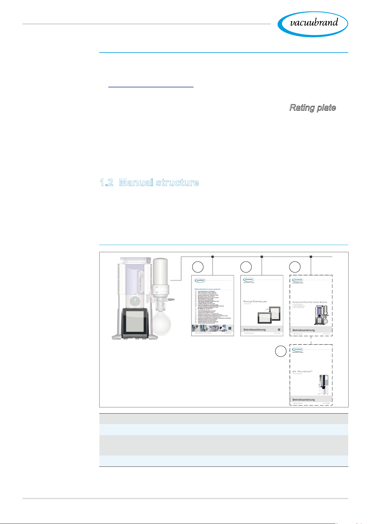
The manuals have a modular structure with separate instruction
modules for the controller, vacuum pumps, pumping units, and
any accessories.
Instruction modules
Example
Breakdown of the
instructions for use
1
1
Safety information for vacuum equipment
2
Description: Vacuum controller – control and operation
3
Optional description: Pumping unit or vacuum pump – connec‑
2
3
4
tion, operation, maintenance, mechanics
4
Optional description: Accessories
8 20901059_EN_VACUU·SELECT_V1.3_280119
Page 9
1.3 About this document
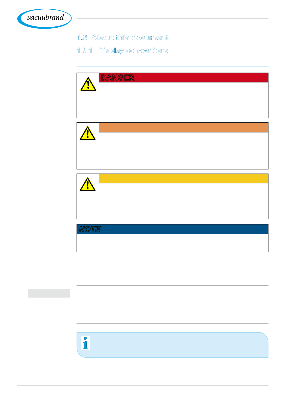
1.3.1 Display conventions
Warning levels
Introduction
Display conventions
DANGER
Indicates an imminent hazardous situation.
Disregarding the situation could result in extremely
serious injury or death.
Take appropriate action to avoid dangerous situations!
WARNING
Warns of a potentially hazardous situation.
Disregarding the situation could result in serious injury
or death.
Take appropriate action to avoid dangerous situations!
CAUTION
Indicates a potentially hazardous situation.
Disregarding the situation could result in minor injury or
damage to property.
Take appropriate action to avoid dangerous situations!
IMPORTANT!
NOTE
Indicates a potentially harmful situation.
Disregarding the situation could result in damage to property.
Additional notes
Information or specic recommendation which must be
observed.
Important information for trouble‑free operation of your
product.
Helpful tips + tricks
Additional information
920901059_EN_VACUU·SELECT_V1.3_280119
Page 10
Introduction
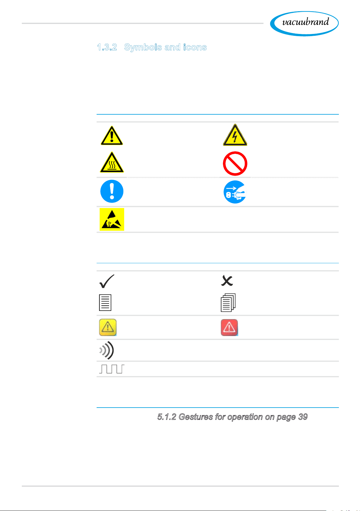
1.3.2 Symbols and icons
This manual uses symbols and icons. Safety symbols indicate
specic risks associated with handling the product. Symbols and
icons are designed to help you identify risks more easily.
Safety symbols
Explanation of safe‑
ty symbols
Additional symbols
General warning symbol. Danger: electricity.
Warning: hot surface. General prohibition sign.
General mandatory sign. Disconnect power plug.
Electrostatically sensitive
components ESD.
Additional symbols and icons
Positive example – Do this!
Result – OK
Refers to content in this
manual.
Negative example –
Don't do this!
Refers to content in other
supplementary documents.
Indication: Warning Indication: Error
Acoustic signal – signal sound/warning sound.
Frequency of beeping, frequency of acoustic signal
Symbols and gestures for operation
See chapter: 5.1.2 Gestures for operation on page 39
10 20901059_EN_VACUU·SELECT_V1.3_280119
Page 11
Additional detailed descriptions of symbols (icons) and
signals on the display can be found in chapter
and operating elements.
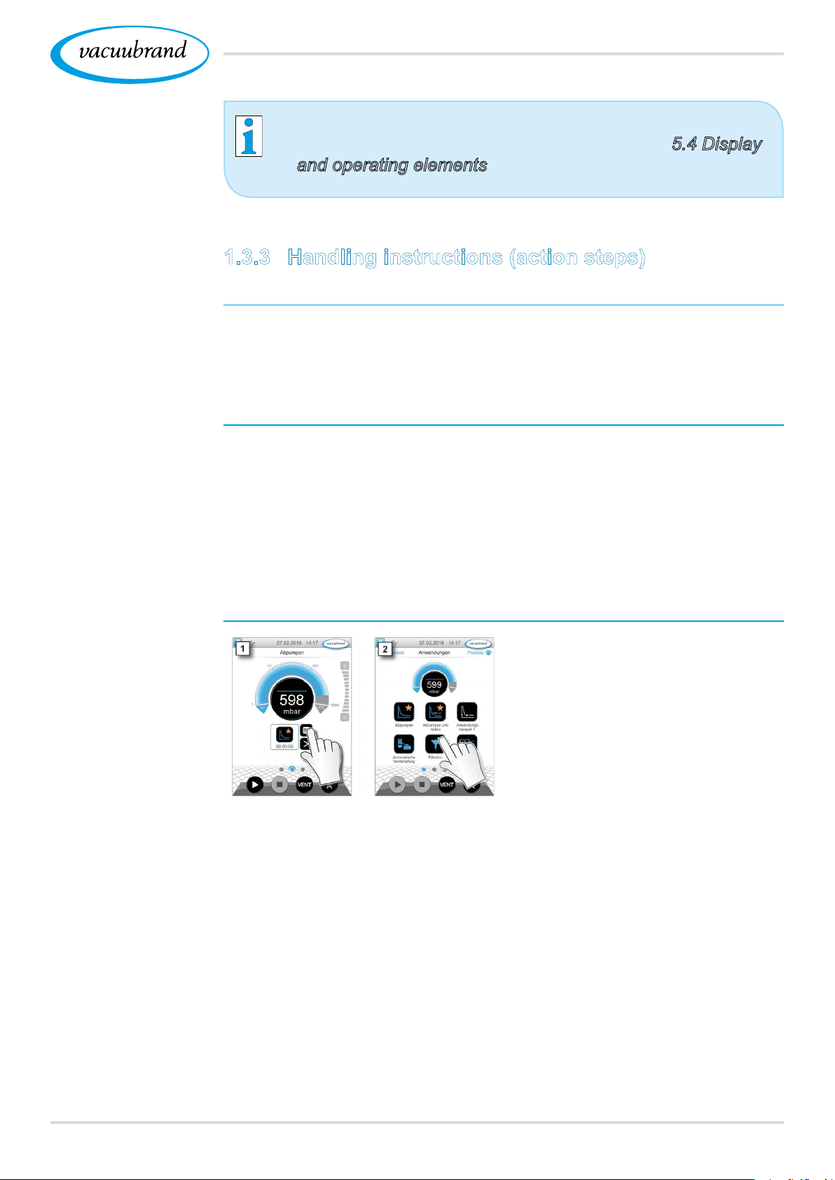
1.3.3 Handling instructions (action steps)
Introduction
5.4 Display
Action steps as text
Schematic diagram
Action steps as
graphics
Instructions (single step)
Perform the step described.
5 Result of action
Instructions (multiple steps)
1. First step
2. Next step
5 Result of action
Perform the steps in the order described.
Instructions (shown graphically)
1. First step
2. Next step
5 Result of action
1120901059_EN_VACUU·SELECT_V1.3_280119
Page 12

Introduction
1.3.4 Abbreviations
Abbreviations
abs. Absolute
AK Separator ask
ATM Atmospheric pressure (bar graph, program)
(di)
di
Interior diameter
DN Nominal diameter
EX* Outlet
FKM Fluoroelastomer
FC Frequency converter
GB Gas ballast
‑‑‑ ‑‑‑
Gr. Size
hh:mm:ss Time in hours/minutes/seconds
hPa Pressure unit, hectopascal (1 hPa = 1 mbar =
0.75 Torr)
IN* Inlet
KF Small ange
max. Maximum value
min. Minimum value
mbar Pressure unit, millibar (1 mbar = 1 hPa = 0.75 Torr)
PA Polyamide
PBT Polybutylene terephthalate
PC .... Pumping unit chemistry with series identication
number
PE Polyethylene
RMA no. Return Merchandise Authorization number
SW Wrench size (tool)
Torr Pressure unit (1 Torr = 1.33 mbar = 1.33 hPa)
USB Universal serial bus
VAC Vacuum (pressure curve)
resp. Responsible
VMS‑B Vacuum management system – module
e. g. For example
* Labeling on the vacuum pump
12 20901059_EN_VACUU·SELECT_V1.3_280119
Page 13

1.3.5 Term denitions
Introduction
Product‑specic
terms
PC 3001 VARIO
select *
Vacuum pumping unit with variable speed
motor for precise vacuum control includ‑
ing VACUU·SELECT® controller and
VACUU·SELECT® Sensor.
PC 510 select ** Pumping unit with valve‑actuated vacuum
control.
VACUU·BUS
®
Bus system from VACUUBRAND for com‑
munication between peripheral devices with
VACUU·BUS®‑enabled gauges and control‑
lers. The maximum permissible cable length is
30 m.
VACUU·BUS®
address
Address which enables the VACUU·BUS® cli‑
ent to be unambiguously assigned within the
bus system, e.g., for connecting multiple sen‑
sors with the same measurement range.
VACUU·BUS®
client
Peripheral device or component with
VACUU·BUS® port which is integrated in the
bus system, e.g., sensors, valves, level indica‑
tors, etc.
VACUU·BUS®
conguration
Assigning a different VACUU·BUS® address to
a VACUU·BUS® component using a gauge or
controller.
VACUU·BUS®
connector
VACUU·LAN
®
4‑pin round connector for the bus system from
VACUUBRAND.
Local vacuum network.
VACUU·SELECT®Vacuum controller, controller with touchscreen;
consisting of operating panel and vacuum sen‑
sor.
VACUU·SELECT®
Sensor ***
External vacuum sensor
for VACUU·SELECT®
or
separately as an independent vacuum sensor.
* Also valid for: PC 3002 VARIO select, PC 3003 VARIO select,
PC 3004 VARIO select
** Also valid for: PC 510 select, PC 511 select, PC 520 select, PC 610 select,
PC 611 select, PC 620 select
*** Available with and without venting valve
1320901059_EN_VACUU·SELECT_V1.3_280119
Page 14
Safety information
2 Safety information
The information in this chapter must be observed by everyone
who works with the product described here.
The safety information is valid for the entire life cycle of the prod‑
uct.
2.1 Usage
Only use the product if it is in perfect working condition.
2.1.1 Intended use
Intended use
The VACUU·SELECT® vacuum controller is a laboratory instru‑
ment which, with appropriate peripheral devices1, is intended to
regulate absolute pressure in the area of rough and ne vacuum.
The device may only be used indoors in a non‑explosive
atmosphere. It is designed for continuous operation between
10 °C–40 °C.
Intended use also includes:
observing the information in the document Safety information
for vacuum equipment,
observing the manual,
observing the manual of connected components,
using only approved accessories or spare parts.
Any other use is considered improper use.
2.1.2 Improper use
Improper use
14 20901059_EN_VACUU·SELECT_V1.3_280119
Incorrect use or any application which does not correspond to
the technical data may result in injury or damage to property.
1 For vacuum pumps, sensors and accessories from VACUUBRAND
see also 3.3 VACUU·BUS® peripheral devices on page 26
Page 15
Improper use includes:
Safety information
Improper use
using the product contrary to its intended use,
operation under inadmissible environmental and operating condi‑
tions,
vacuum control of potentially explosive atmospheres which does
not correspond to the ATEX authorization of the sensor see
sensor rating plate,
operation despite obvious faults or defective safety devices,
usage despite incomplete assembly,
pulling plug‑in connections on the cable out of the socket,
use in mines or underground.
2.1.3 Foreseeable misuse
In addition to improper use, there are types of use which are
prohibited when handling the device:
Possibly
foreseeable
misuse
installation and operation in potentially explosive atmospheres,
unauthorized extensions or conversions, in particular when these
impair safety,
fully exposing the device to the vacuum, immersing it in liquids,
exposing it to water spray or steam jets,
vacuum control of hot, unstable, or explosive media,
operation with sharp‑edged objects,
switching the device on/off with tools or one's foot.
1520901059_EN_VACUU·SELECT_V1.3_280119
Page 16
Safety information
2.2 Target group description
IMPORTANT!
Meaning
Personnel
qualication
Responsibility
matrix and areas of
competence
Users in the areas of competence in the Responsibility matrix
must possess the relevant qualications for the activities listed.
2.2.1 Personnel qualication
Operators Laboratory staff, such as chemists, laboratory techni‑
cians
Specialist Person with professional qualication in mechanics,
electrical equipment or laboratory devices
Responsible spe‑
cialist
Similar to a specialist, with additional specialist
responsibility, or responsibility for a department or di‑
vision
2.2.2 Responsibility matrix
Activity
Operators Specialist
Installation x x x
Commissioning x x x
Network integration x
Updates
Data import/export
Data logger download
Troubleshooting
X X X
X X X
X X
X X
Operation x x x
Advanced operation x x
Error report x x x
Remedy
Changing circuit board
fuse
(x)
x x
x x
Repair order x
Cleaning, simple x x x
Sensor cleaning*
Sensor calibration*
X X
X X
Shutdown x x x
Decontamination** x x
Responsible
specialist
* Option
** Alternatively,arrangefordecontaminationbyaqualiedserviceprovider
16 20901059_EN_VACUU·SELECT_V1.3_280119
Page 17
2.2.3 Personal responsibility
Safety information
Work safely
Protective clothing
Quality standard
and
safety
The safety and protection of individuals has top priority. Activities
and processes which represent a potential safety hazard are not
permitted.
Always be conscious of safety and work in a safe manner. Ob‑
serve instructions issued by the operator, and national regula‑
tions on accident prevention and industrial safety.
Use the controller only if you have understood its function
and this manual.
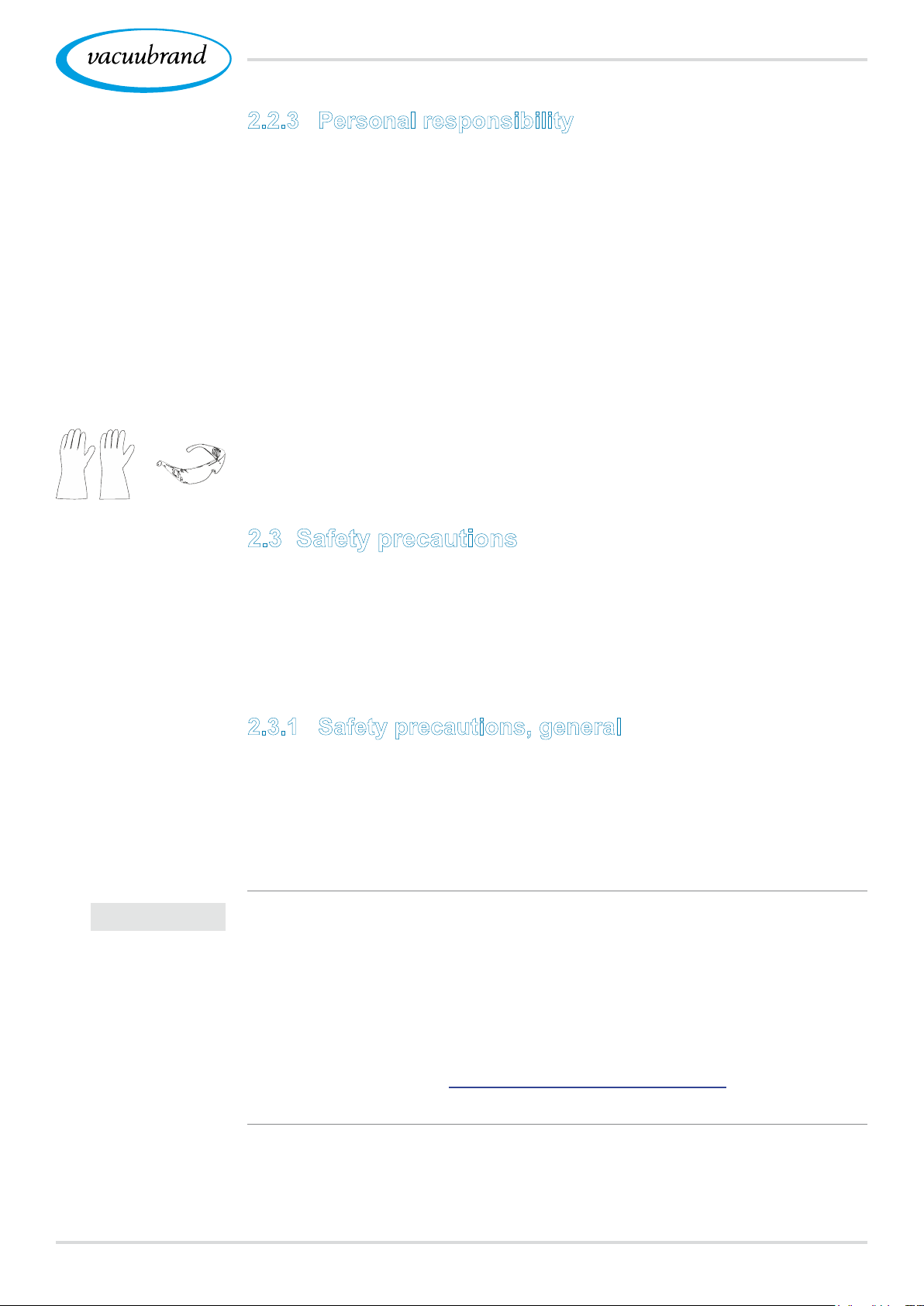
In the case of activities which require protective clothing, per‑
sonal protective equipment as specied by the operator is to
be worn.
2.3 Safety precautions
Products from VACUUBRAND GMBH + CO KG are subject to
stringent quality testing with regard to safety and operation. Each
product undergoes a comprehensive test program prior to deliv‑
ery.
IMPORTANT!
2.3.1 Safety precautions, general
When handling contaminated parts, follow the relevant regula‑
tions and safety precautions.
Repairs are only to be carried out by the manufacturer’s Ser‑
vice Department.
Prior to any service, contamination from hazardous sub‑
stances needs to be excluded.
Please note that residual process media may pose a danger
to people and the environment. Take suitable decontamina‑
tion measures.
Before sending devices to our Service Department, you
must rst ll out a Health and Safety Clearance form, sign it
to conrm the information, and return it to us.
1720901059_EN_VACUU·SELECT_V1.3_280119
Page 18
Safety information
2.3.2 Awareness of potential dangers
Vacuum control of critical processes
Risk of explosion
during critical
processes
IMPORTANT!
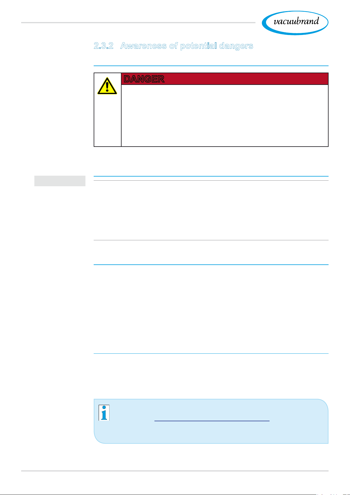
DANGER
Risk of explosion through control of critical
processes.
Depending on the process, an explosive mixture can
form in systems.
The control of critical processes must always be su‑
pervised!
Damaged components
Damaged components, especially those which impair safety,
must be promptly replaced.
Ensure that you are not working with damaged components.
Replace defective parts immediately, e.g., a broken cable or
faulty plug.
Electrical energy
Safety during
servicing
Dangers due to electrical energy
After the controller has been switched off and disconnected from
the power supply, there may still be dangers at the plug‑in power
supply due to residual energy:
Replace the plug‑in power supply if there are any defects.
Never open the plug‑in power supply.
Service shipments
Devices which represent a potential safety hazard should be sent
in, maintained or repaired only if all hazardous contamination has
been removed.
The form for conrming safety is available as a PDF on our
website: Health and Safety Clearance form.
18 20901059_EN_VACUU·SELECT_V1.3_280119
Page 19

Safety information
2.3.3 ATEX equipment category (sensor)
Installation and potentially explosive atmospheres
The installation and operation of the operating panel in areas
where potentially explosive atmospheres can develop to a
hazardous degree is not permitted.
ATEX approval2 of vacuum sensors only applies to the internal,
wetted parts of the sensor, not to its surroundings.
ATEX equipment labeling
ATEX
equipment category
ATEX
approval
Prevent explosive
mixtures
Vacuum equipment labeled with ` has ATEX approval in line
with the ATEX marking on the rating plate.
Only use the product if it is in perfect working condition.
The devices are designed for a low level of mechanical
stress and must be installed in such a way that they cannot
sustain mechanical damage from the outside.
After any work on the device, check its leak rate.
When using the device on equipment with potentially explosive
atmospheres (according to ATEX approval), modications to the
device are not permitted and will invalidate the ATEX approval.
Wetted parts attached to the device must have ATEX approval
at least equivalent to that of the device itself, and must not ad‑
versely affect the ATEX approval of the device, in particular the
temperature in the wetted area.
The use of gas ballast and/or venting valves is only permitted if
this would not normally, or only rarely, cause explosive mixtures
within the device, or do so only for a short time.
If necessary vent with inert gas.
Information on the ATEX equipment category is also available on
our website at: www.vacuubrand.com/.../Information‑ATEX
2 -> See rating plate: VACUU·SELECT Sensor, VACUU·VIEW (extended),
VSK 3000
1920901059_EN_VACUU·SELECT_V1.3_280119
Page 20
Safety information
2.4 Disposal
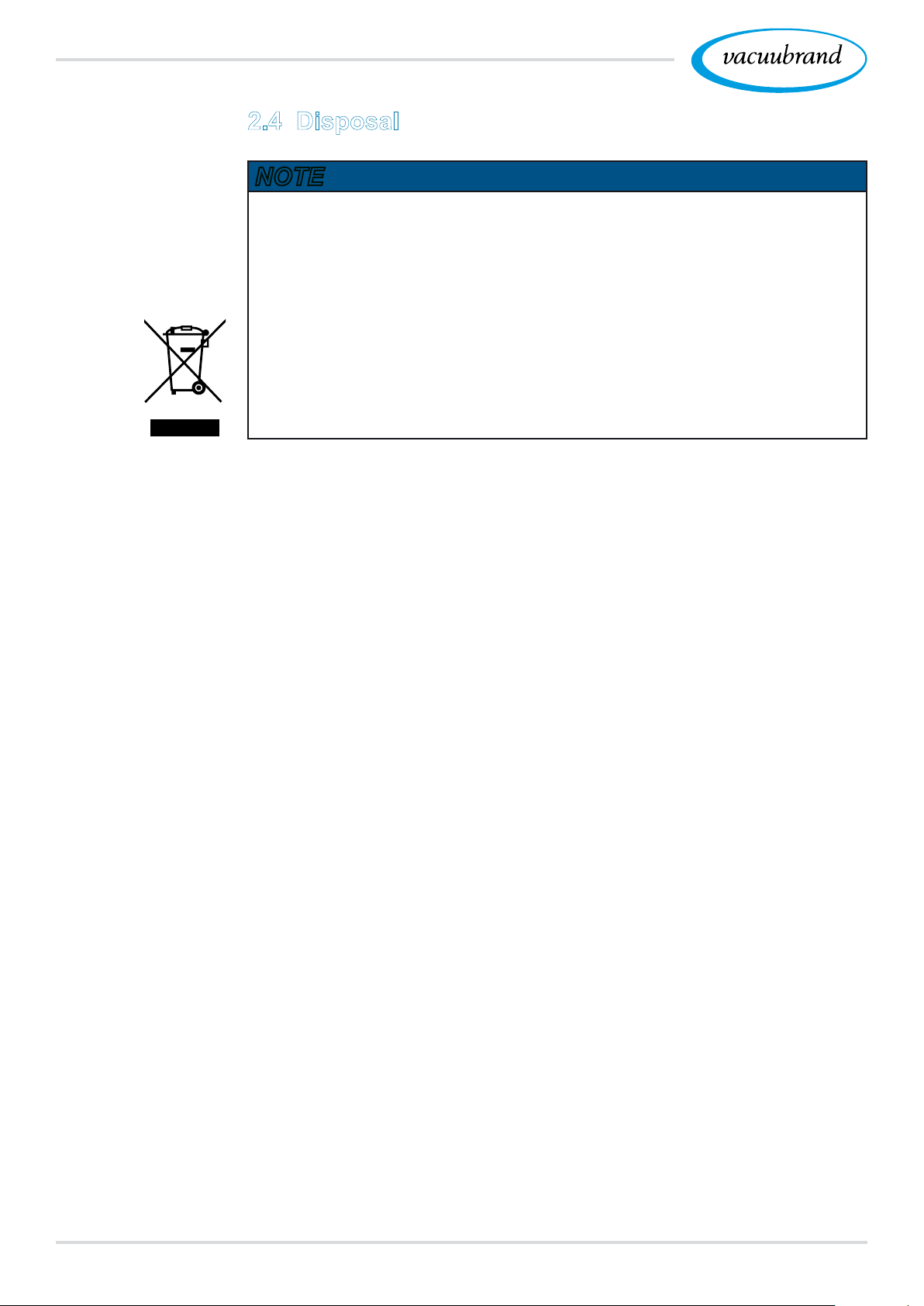
NOTE
Risk of environmental damage due to incorrect disposal of
the product.
Do not dispose of with household waste!
Electronic components are subject to hazardous waste treat‑
ment and must only be disposed of by certied specialists.
Observe the national regulations for safe disposal and envi‑
ronmental protection.
Detailed information on the respective regulations can be
obtained from your local administrative authority.
20 20901059_EN_VACUU·SELECT_V1.3_280119
Page 21
Product description
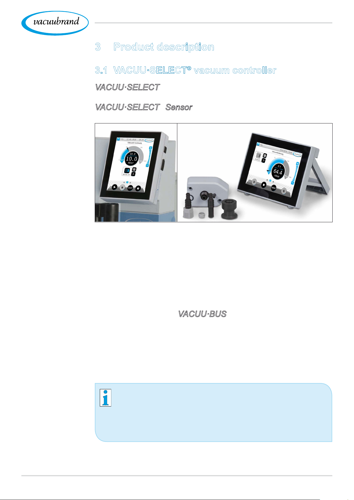
3 Product description
3.1 VACUU·SELECT® vacuum controller
Description of
vacuum controller
VACUU·SELECT® is a vacuum controller consisting of an
operating panel and an external vacuum sensor, e. g., the
VACUU·SELECT® Sensor.
The controller was developed for applications which require a
controlled vacuum. Various applications and menus are available
for operation and vacuum control. The controller is operated us‑
ing the touchscreen. The menus are designed to be user friendly.
Depending on the type of operation and peripheral devices con‑
nected, the controller regulates the process vacuum subject to
demand.
As a component of the VACUU·BUS® system, the controller offers
numerous connection options for a wide variety of applications.
Vacuum processes are controlled via vacuum pumps, in‑line so‑
lenoid valves and/or venting valves. If several valves of one type
are connected, they switch simultaneously, e.g., multiple venting
valves.
To control a vacuum, a minimum combination of the
controller, a vacuum sensor, valves and/or vacuum pumps
is needed.
If only the built‑in sensor is present, vacuum control is
not possible.
2120901059_EN_VACUU·SELECT_V1.3_280119
Page 22
Product description
3.2 Product views
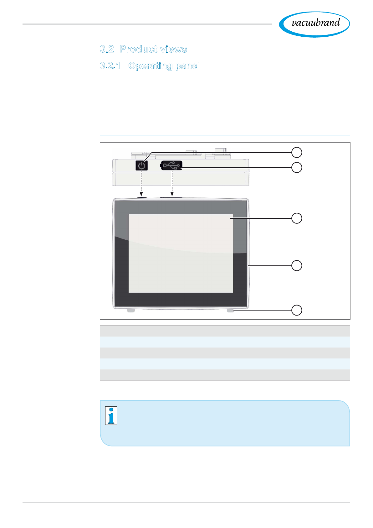
3.2.1 Operating panel
The operating panel has a color display with a touchscreen.
Depending on the type of installation, the display can be rotated
by 90°.
Top view + front view
Top view
Front view
1
2
3
4
5
Meaning
1
ON/OFF button
2
Cover of USB port, type A*
3
Screen
4
Chemically resistant plastic housing
5
Rubber feet
USB type A* is only suitable for connecting USB ash
drives or WiFi USB dongles, and not for connection to a
USB master, such as a PC.
22 20901059_EN_VACUU·SELECT_V1.3_280119
Page 23
Interfaces at the
back
Product description
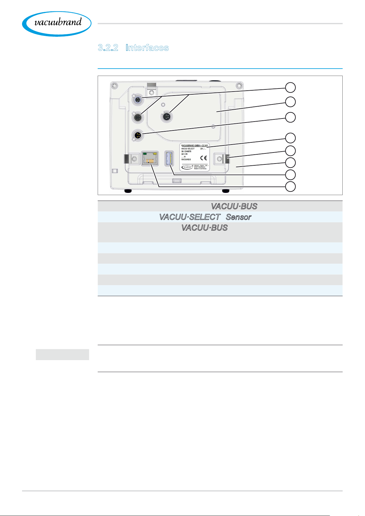
3.2.2 Interfaces
Rear view
6
7
8
9
10
11
12
13
Meaning
IMPORTANT!
6
3x connection sockets for VACUU·BUS® components
7
Recess for VACUU·SELECT® Sensor
8
Power supply via VACUU·BUS®, plug‑in power supply connec‑
tion or vacuum pump/pumping unit
9
Rating plate
10
Option: Spring clip as xing for built‑in version
11
Stand for desktop version, foldable
12
USB port, type A
13
RJ45 socket – LAN connection
Note: The VACUU·BUS® ports are each equipped with a guide slot as an anti-
rotation device and connection coding for VACUU·BUS® sockets and
connectors.
Do not use the USB ports as distributors, except for USB
hubs with their own power supply.
2320901059_EN_VACUU·SELECT_V1.3_280119
Page 24
Product description
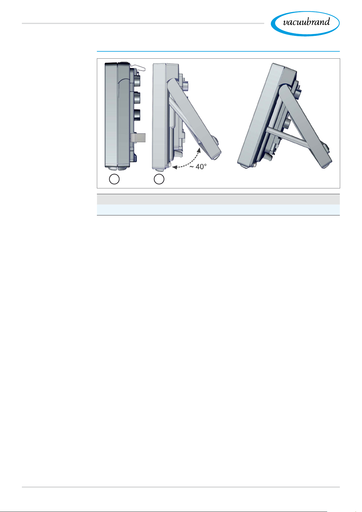
Side view
Side view
A B
Meaning
A
Mounted spring clips – xing for built‑in version
B
Stand and brace extended for desktop version
24 20901059_EN_VACUU·SELECT_V1.3_280119
Page 25
Product description
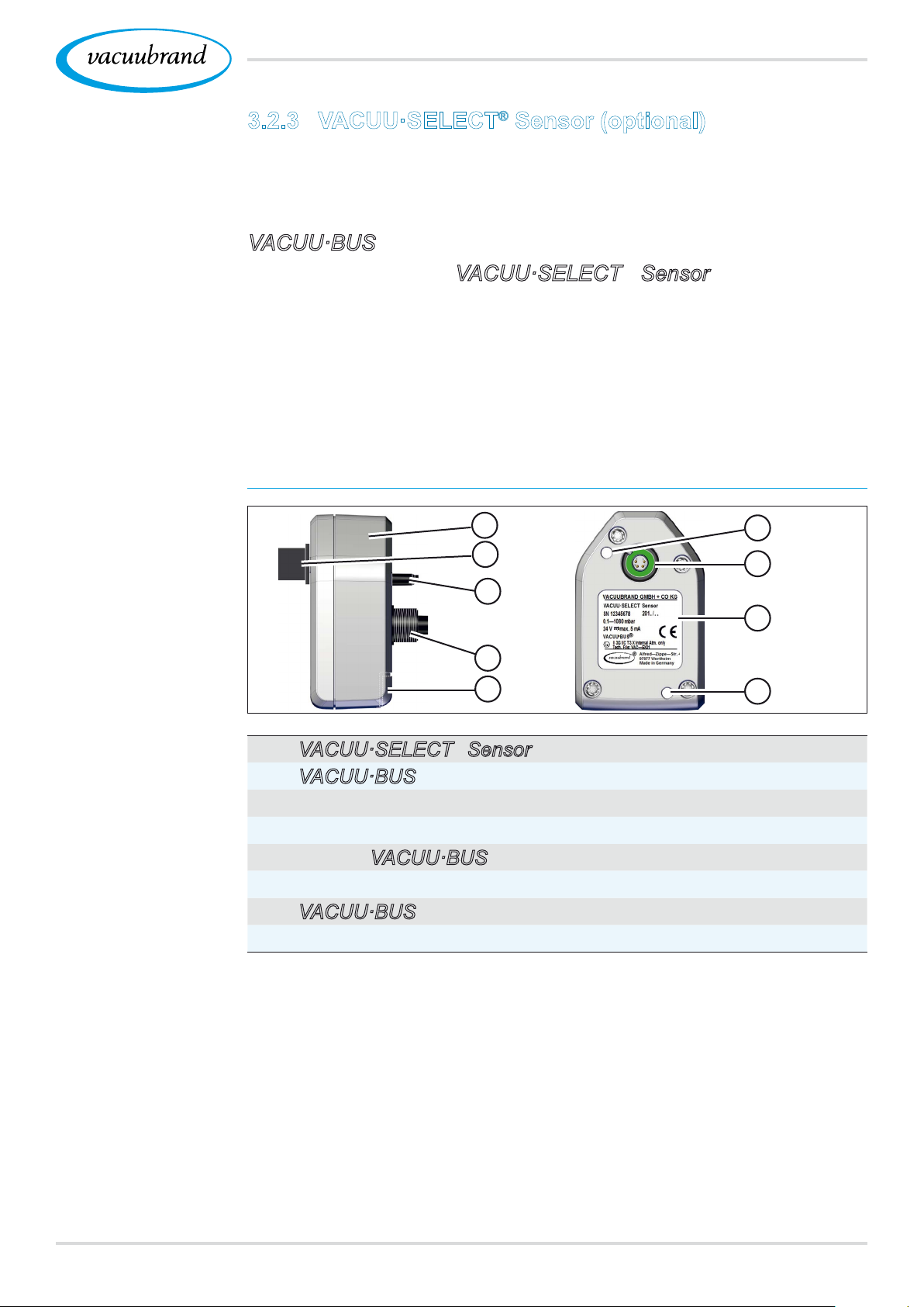
3.2.3 VACUU·SELECT® Sensor (optional)
Description of
VACUU·SELECT®
Sensor
Side view, top view
The vacuum sensor for this product is mounted externally, e. g.,
on the controller housing, on the application or in the pumping
unit. Communication with the controller takes place via the
VACUU·BUS.
Two versions of the VACUU·SELECT® Sensor are available –
with or without venting valve.
The vacuum sensor with high chemical resistance is designed
for measurements in the rough vacuum range. There are three
options for the vacuum connection: small ange, hose nozzle or
direct hose connection.
Side view, top view
1
2
3
6
7
Meaning
4
5
1
VACUU·SELECT® Sensor
2
VACUU·BUS® plug attachment, detachable (option)
3
Venting valve (option)
4
Vacuum screw connection
5
Port for VACUU·BUS® plug attachment (park position)
6
Hole for screws
7
VACUU·BUS® port
8
Rating plate
8
6
2520901059_EN_VACUU·SELECT_V1.3_280119
Page 26
Product description
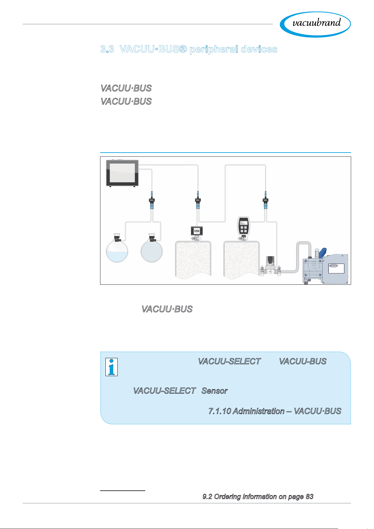
3.3 VACUU·BUS® peripheral devices
External valves, level sensors and vacuum sensors (up to the ne
vacuum range) are components which can be connected via the
VACUU·BUS® directly to the controller.
VACUU·BUS® components can be easily added or removed at
any time via component detection. Component activation permits
the activation or deactivation of connected components.
VACUU·BUS components1 (clients)
Example
VACUU·BUS
principle
with different
components
When the controller is switched on, it checks the current con‑
guration. VACUU·BUS® components are automatically detected
and are used and monitored until the controller is switched off. If a
previously connected component is no longer found, the control‑
ler displays an error message.
In the case of the VACUU-SELECT®, all VACUU-BUS®
components can be individually activated or deactivated
without disconnecting the plug. The venting valve of a
VACUU-SELECT® Sensor can also be easily deactivated at
the controller.
See also chapter:
7.1.10 Administration – VACUU·BUS
1 See also table in chapter: 9.2 Ordering information on page 83
26 20901059_EN_VACUU·SELECT_V1.3_280119
Page 27
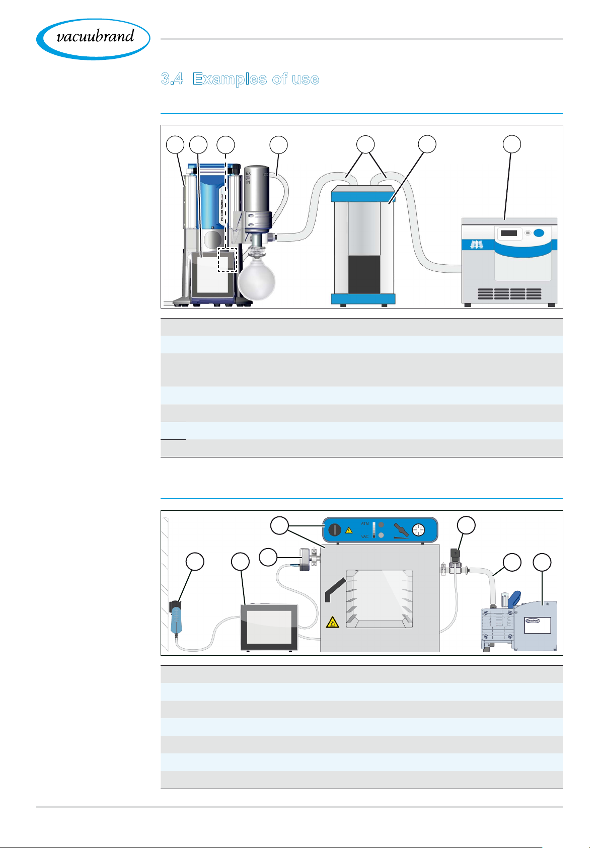
Example
Vacuum concen‑
trator
3.4 Examples of use
Vacuum concentrator
21
3
4
Product description
5
6
7
Meaning
Example
Vacuum drying
1
PC 3001 VARIO select vacuum pumping unit
2
VACUU·SELECT® operating panel, removable
3
VACUU·SELECT® Sensor permanently mounted in the pump‑
ing unit
4
Exhaust hose (diverted into an exhaust hood)
5
Vacuum hose
6
Example: Cold trap
7
Example: Vacuum concentrator
Vacuum drying
1
2
4
3
5
6
7
Meaning
1
Plug‑in power supply
2
VACUU·SELECT
3
VACUU·SELECT® Sensor
4
Vacuum drying cabinet with its own control unit
5
Vacuum valve
6
Vacuum hose
7
Diaphragm pump, vacuum pump
®
2720901059_EN_VACUU·SELECT_V1.3_280119
Page 28
Installation and connection
4 Installation and connection
4.1 Transport
Products from VACUUBRAND are packed in sturdy, recyclable
packaging.
The original packaging is accurately matched to your
product for safe transport.
If possible, please keep the original packaging, e. g., for
returning the product for repair.
Goods receipt
Check incoming
goods
Check installation
conditions
Check the shipment for transport damage and completeness.
Immediately report any transport damage in writing to the
supplier.
Compare the scope of delivery with the delivery note.
4.2 Installation
Check installation conditions
The device is acclimatized.
Ambient conditions have been observed and are within the lim‑
itation of use.
Limitation of use
Ambient temperature 10–40 °C 50–104 °F
Max. altitude 2000 m
above sea level
Relative humidity 30–85 %, non‑condensing
Protection class (front) IP 20
Prevent condensation or contamination from dust, liquids, or corrosive
gases.
(US)
6562 ft
above sea level
IMPORTANT!
Note the IP protection class of the controller.
IP protection is only guaranteed if the controller is appropri‑
ately mounted or installed.
28 20901059_EN_VACUU·SELECT_V1.3_280119
Page 29
Installation and connection
NOTE
Condensate can damage the electronics.
A large temperature difference between the storage location
and the installation location can cause condensation.
After goods receipt or storage, allow your vacuum device to
acclimatize for at least 3‑4 hours before initial use.
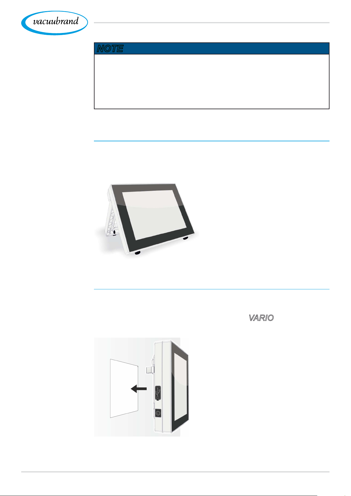
Desktop version
Use as desktop
device
Use as built‑in
device
If the stand is extended backwards and secured with the brace,
the controller can be set up directly on the work surface and con‑
nected, for example, on the lab bench.
Built‑in version*
Holders are integrated in the controller or spring clips can be
mounted for installation. The operating panel of the controller can
then be directly clipped into a cut‑out in a VARIO® pumping unit,
lab furniture, or a control cabinet.
* The stand is attached to the device, i.e.,
the built-in version can be extended at any
time for use as a desktop version.
2920901059_EN_VACUU·SELECT_V1.3_280119
Page 30
Installation and connection
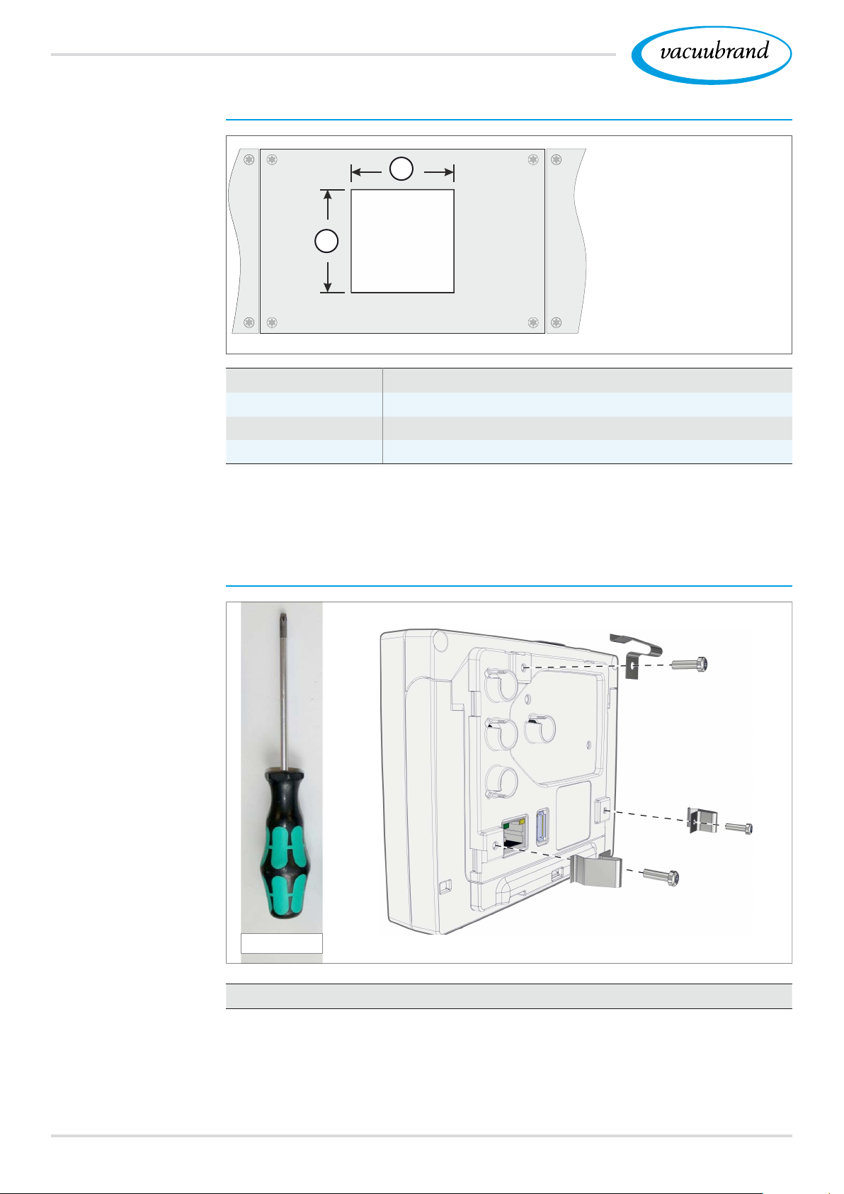
Installation cut‑out (in control cabinet, lab furniture, cable duct)
Cut‑out dimensions
Wall thickness Dimensions (a) for installation cut‑out
1 mm 0.04 in. 111.5 mm x 111.5 mm 4.39 in. x 4.39 in.
2 mm 0.08 in. 112 mm x 112 mm 4.41 in. x 4.41 in.
3 mm 0.12 in. 112.5 mm x 112.5 mm 4.43 in. x 4.43 in.
a
a
Mount spring clips
Depending on the thickness of the wall, appropriate tolerances
should be allowed for the installation cut‑out.
Mount spring clips
Torx T10
Spring clips + screw ttings D3 x 10
30 20901059_EN_VACUU·SELECT_V1.3_280119
20636593
Page 31
Installation and connection
4.3 Sensor connection
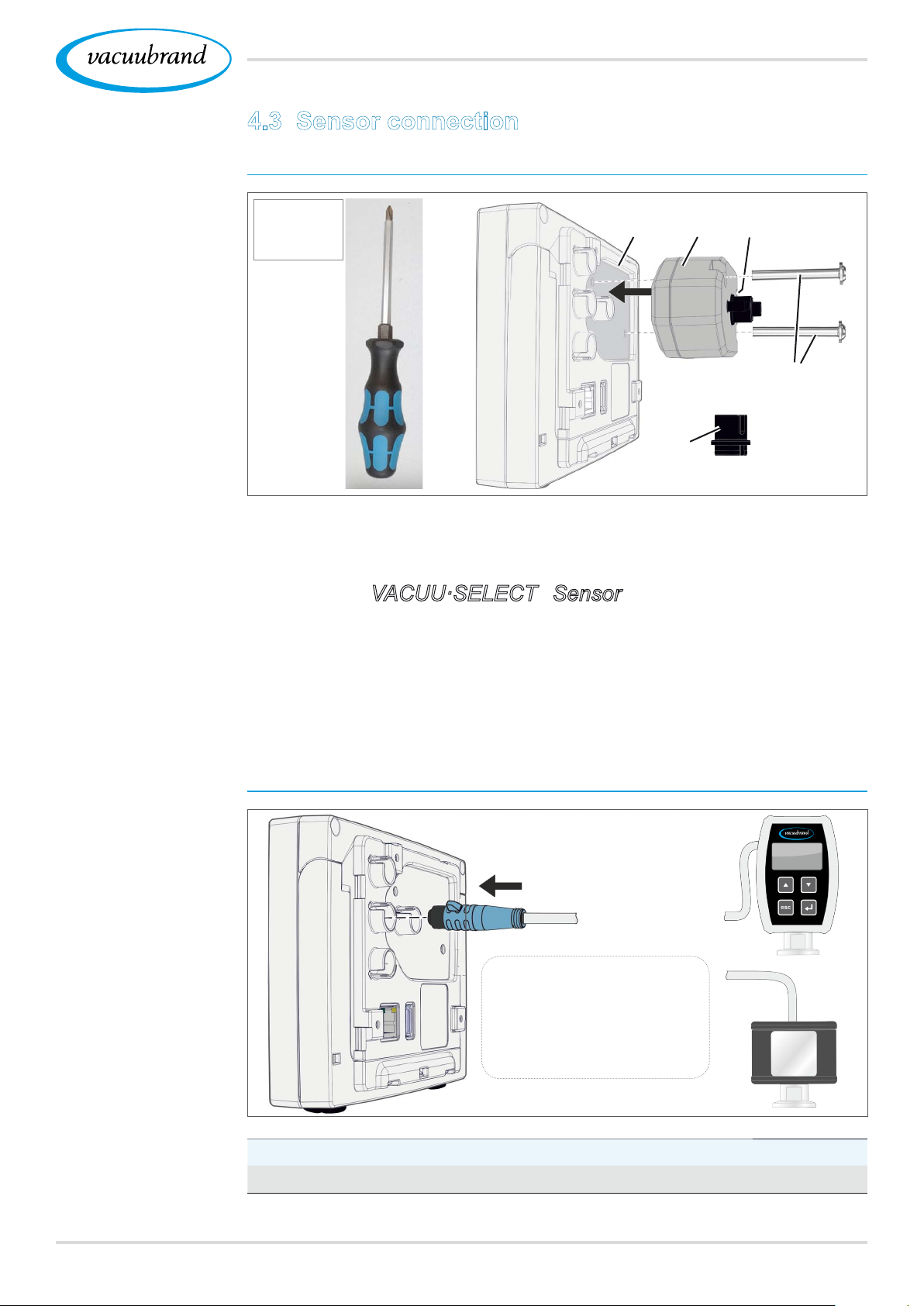
Connect and mount the VACUU·SELECT® Sensor
Mount and
connect the
VACUU·SELECT®
Sensor
Phillips
Gr. 2
(b)
(c)
(d)
(e)
(a)
1. Pull out the VACUU·BUS® plug attachment (a) and insert it
into (d).
2. Insert the VACUU·SELECT® Sensor (c) into the
VACUU·BUS® port of the controller (b) in the preformed
recess.
Example
Connection of other
vacuum sensors
3. Use the Phillips screwdriver to tighten the 2 screws (e) until
hand‑tight.
Connect other vacuum sensors (option)
VACUU·VIEW
VACUU·VIEW extended
VSK 3000
VSP 3000
VACUU·SELECT® Sensor
VACUU·BUS® extension cable 2 m
VACUU·BUS® Y adapter
20612552
20636656
3120901059_EN_VACUU·SELECT_V1.3_280119
Page 32
Installation and connection
4.4 Electrical connection
IMPORTANT!
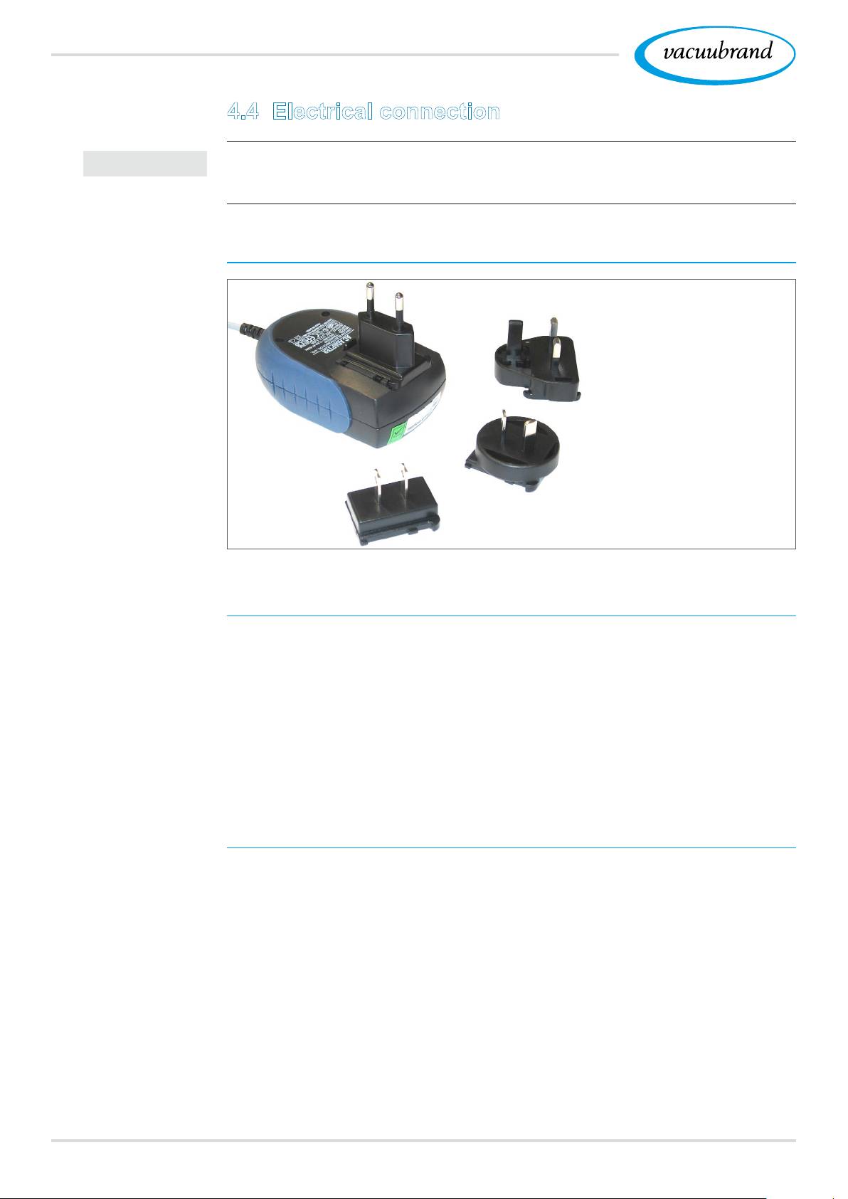
Plug‑in power
supply
Lay the connection cable such that it cannot be damaged by
sharp edges, chemicals, or hot surfaces.
Power supply via plug‑in power supply*
* Short circuit-proof wide
range power supply unit
with integrated overload
protection and country-spe-
cicplugattachments
Prepare connection
Remove plug
attachment from
power supply unit
Prepare plug‑in power supply
1. Take the power supply unit and the plug attachments out of
the packaging.
2. Select the plug attachment which ts your socket.
3. Place the plug attachment onto the metal contacts of the
power supply unit.
4. Push the plug attachment until it clicks into place.
Remove plug attachment
1. Press the locking button on the power supply unit.
2. Remove the plug attachment from the power supply unit.
5 Another plug attachment can now be attached.
32 20901059_EN_VACUU·SELECT_V1.3_280119
Page 33
Power supply via
plug‑in power
supply
Installation and connection
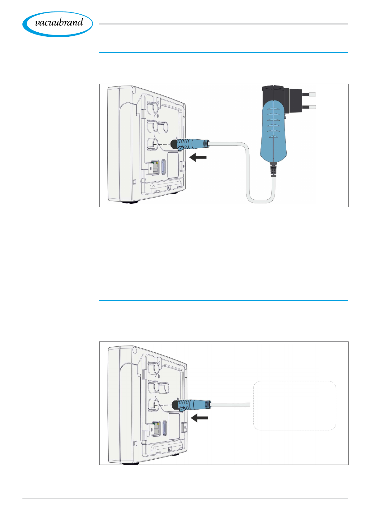
Connect plug‑in power supply to the controller
Insert the VACUU-BUS® cable of the plug‑in power supply
into the plug‑in connection of the controller.
Controller power
supply via periph‑
eral device
Connect power supply
Insert the plug‑in power supply into the power outlet.
5 The green LED on the plug‑in power supply lights up.
Connect power supply via peripheral device
Plug the VACUU-BUS® cable of the peripheral device, such
as a PC 3001 VARIO select chemistry pumping unit, into the
plug‑in connection of the controller.
Chemistry pumping unit
or
diaphragm pump
3320901059_EN_VACUU·SELECT_V1.3_280119
Page 34
Installation and connection
4.5 Vacuum connection
WARNING
Risk of bursting due to overpressure
Prevent uncontrolled overpressure, such as when
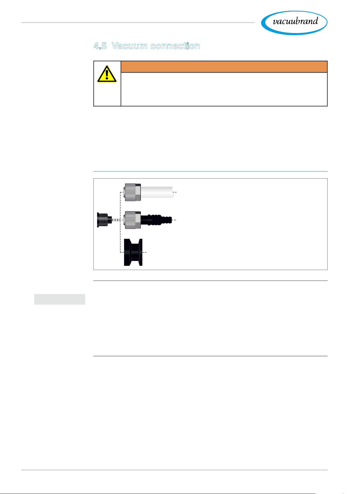
The vacuum connection is made at the connected vacuum sen‑
sor. The connection can be made in various ways.
Connection options
connecting to a locked or blocked tubing system.
Connection
options on the
VACUU·SELECT®
Sensor
IMPORTANT!
Connection via PTFE hose DN 8/10, e.g.,
installed in the chemistry pumping unit
or
Connection via hose nozzle DN 6/10,
e.g., desktop controller
or
Connection via small ange KF DN 16,
e.g., physical applications
Use a stable vacuum hose that is suitable for the required
vacuum range.
Keep hose connections to the sensor as short as
possible, or connect the sensor as close as possible to the
application.
Dirt, hose kinks or damage to the sensor connection can
impair the measurement.
34 20901059_EN_VACUU·SELECT_V1.3_280119
Page 35
Connect PTFE hose
Installation and connection
(e)(a) (b)
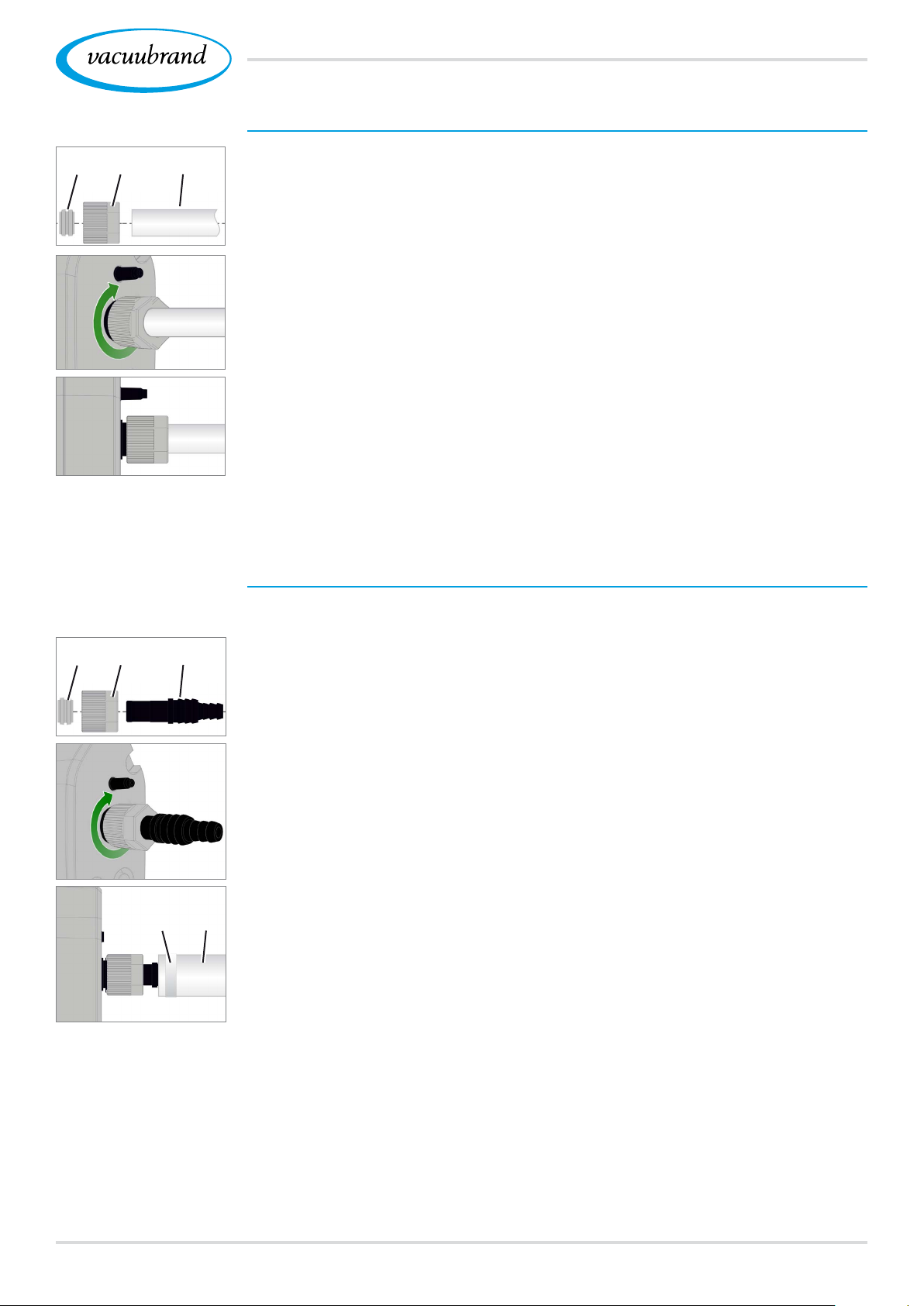
Required connection material: Union nut M14x1, sealing ring,
PTFE hose.
1. Connect the sealing ring (a), the union nut (b) and the PTFE
hose (e) as shown.
2. Push the PTFE hose with the union nut into the vacuum con‑
nection of the sensor and tighten the union nut until hand‑
tight.
Connect sensor via hose nozzle to vacuum
Required connection material: Hose nozzle DN 6/10 mm, union
nut M14x1, sealing ring; optional: vacuum hose and appropriate
(c)(a) (b)
hose clip.
1. Connect the sealing ring (a), the union nut (b) and the hose
nozzle (c) as shown.
2. Push the hose nozzle with the union nut into the vacuum con‑
nection of the sensor and tighten the union nut until hand‑
tight.
(d)(f)
3. Push the vacuum hose (d) from the equipment onto the hose
nozzle and secure the vacuum hose, for example, with a
hose clip (f).
3520901059_EN_VACUU·SELECT_V1.3_280119
Page 36
Installation and connection
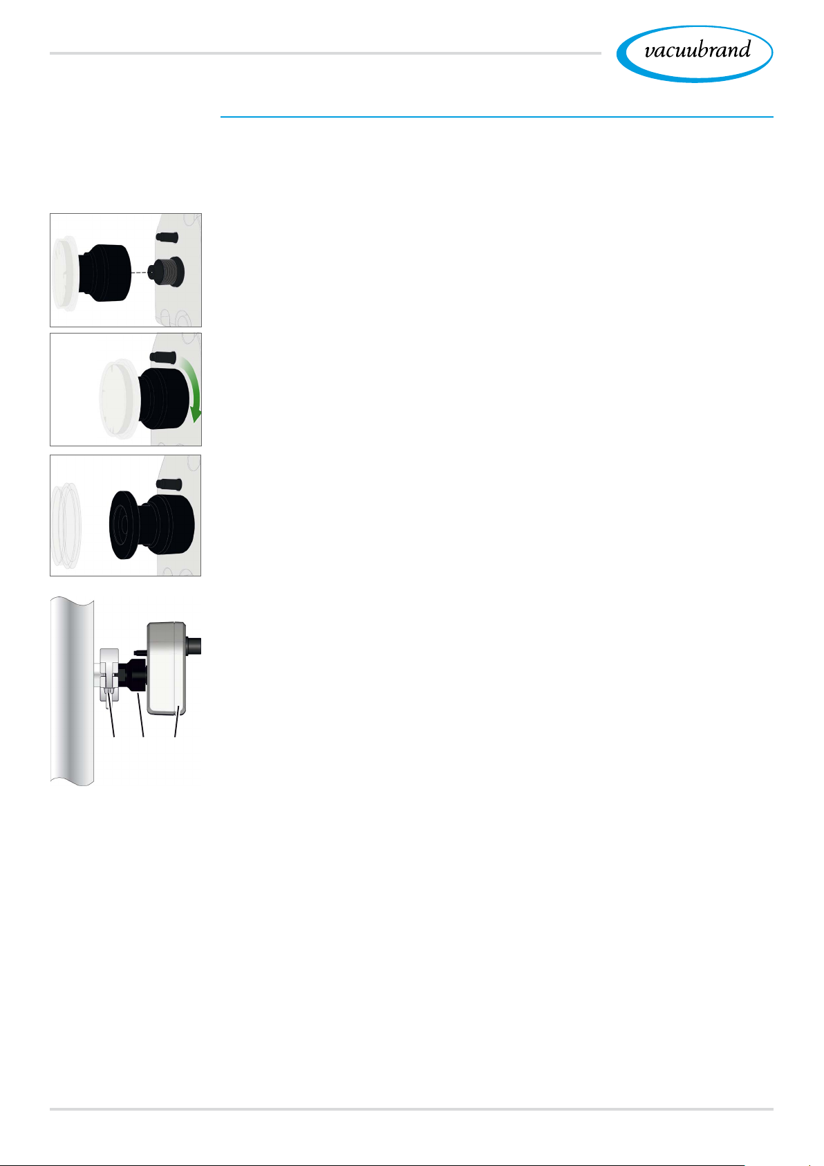
Sensor connection via small ange
Required connection material: VACUU·BUS extension cable
for connection to the controller (option), clamping ring with uni‑
versal centering ring or inner centering ring for KF DN 16 (tool:
open‑end wrench SW17).
1. Remove the blind plug and place the small ange KF DN 16
(b) on the vacuum connection of the sensor (a).
(a)(b)
2. Tighten the small ange KF DN 16 until hand‑tight.
(c)
3. Remove the protective dust cap (c).
4. Place the sensor with the centering ring on the connection of
the equipment small ange KF DN 16 (b).
5. Secure the sensor (a) with the clamping ring (d) to the vacu‑
um line, as shown in the illustration.
(a)(b)(d)
36 20901059_EN_VACUU·SELECT_V1.3_280119
Page 37
Installation and connection
4.6 Venting connection (option)
DANGER
Risk of explosion by venting with air.
Depending on the application, venting can cause explo‑
sive mixtures to form or other hazardous situations to
arise.
Never vent processes with air which could form an
explosive mixture.
If necessary, vent with inert gas
(max. 1.2 bar/900 Torr, abs.).
(a)
(a)
(b)
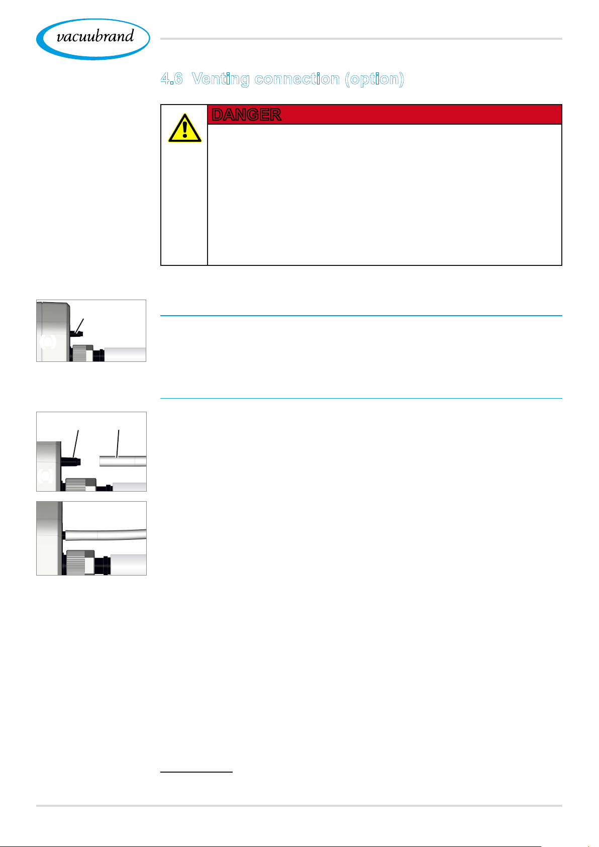
Venting with ambient air
1
For venting (b) with ambient air, nothing needs to be connected
to the sensor (a).
Venting with inert gas – connect venting valve
(c)(b)
Required connection material: Hose for hose nozzle, e.g., sili‑
1
cone tube 4/5 mm
Attach the hose (c) to the connection of the venting valve (b).
5 Venting valve with hose for venting with inert gas2.
1 Not applicable to sensors without an integrated venting valve!
2 Avoid overpressure.
3720901059_EN_VACUU·SELECT_V1.3_280119
Page 38
User interface
Switch on device
5 User interface
5.1 Switch on controller
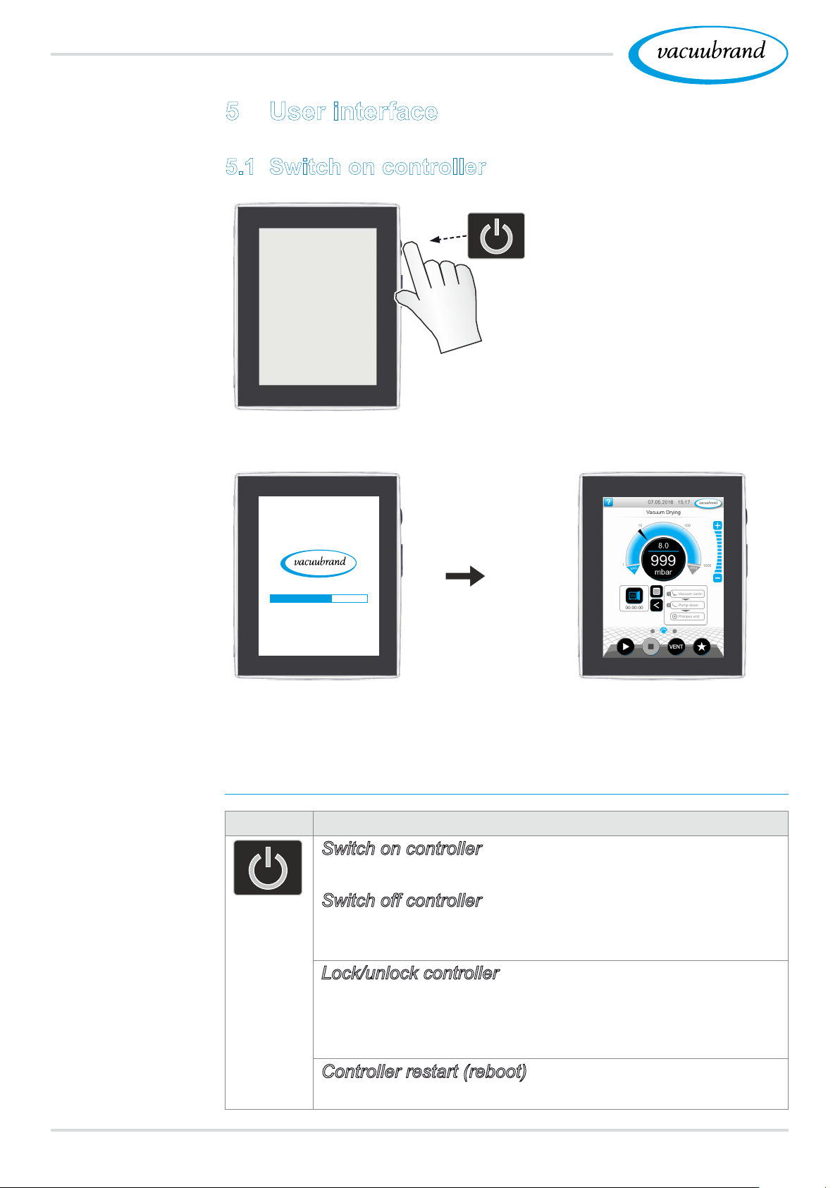
Briey press the ON/OFF button
on the controller
ON/OFF button
5 The device starts up 5 The process screen is
shown
Functions of the ON/OFF button
ON/OFF Meaning
Switch on controller
Briey press ON/OFF button.
Switch off controller
Hold down ON/OFF button for ~3 seconds and conrm
pop‑up.
Lock/unlock controller
Briey press ON/OFF button.
Lock device against unintended operation, e.g., when
cleaning the display.
Controller restart (reboot)
Hold down ON/OFF button for ~10 seconds.
38 20901059_EN_VACUU·SELECT_V1.3_280119
Page 39
5.1.1 Touchscreen
User interface
Touchscreen
operation
Gesture symbols
The controller is a device operated via touchscreen. You can, for
example, select, start, and stop an application by tapping the dis‑
play.
By making various gestures, you can access advanced features:
switch between views, edit applications, or use the help and con‑
text features.
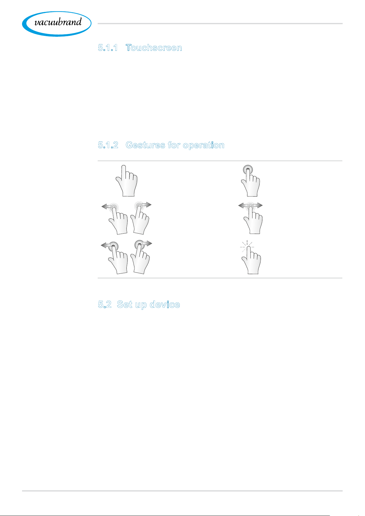
5.1.2 Gestures for operation
Tap/press lightly Press and hold
Tap and swipe in the
indicated direction
Swipe left or right;
both possible
Hold down and drag in
the indicated direction
Drop at this position
5.2 Set up device
To set up the device, follow the instructions on the screen when
switching the device on for the rst time or after restoring the fac‑
tory settings.
3920901059_EN_VACUU·SELECT_V1.3_280119
Page 40
User interface
Example
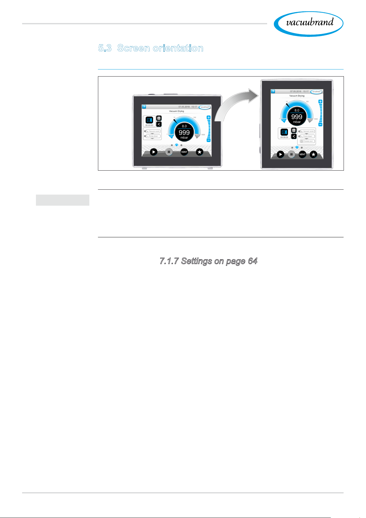
Landscape and
portrait view
5.3 Screen orientation
Supported screen orientations
IMPORTANT!
0°
180°
90°
90°
The following descriptions for operation and function are de‑
scribed in vertical format (portrait). The descriptions are also
valid for horizontal format (landscape), even though the operat‑
ing elements may be arranged slightly differently.
Change the screen orientation
See chapter: 7.1.7 Settings on page 64
40 20901059_EN_VACUU·SELECT_V1.3_280119
Page 41
User interface
5.4 Display and operating elements
The display and operating elements of the controller are summa‑
rized and explained in this chapter.
Refer to this chapter if you want to read about the meaning of
a display or an operating element during operation.
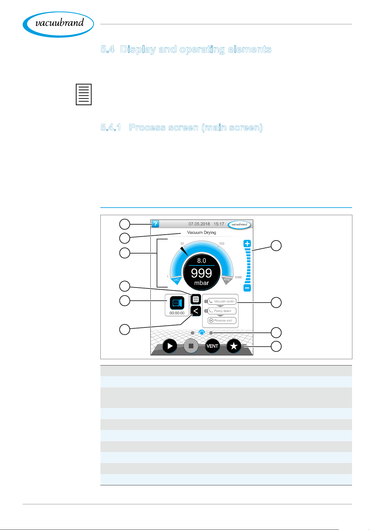
5.4.1 Process screen (main screen)
After the device is switched on, the process screen appears. The
process screen is the main screen of the controller. The display
adapts to the selected application, e.g., by showing the name of
the application, process steps, and target values.
Example
Process screen
with display and
operating elements
Meaning
Elements of the process screen
1
2
3
4
5
6
1
Status bar with help button, date/time, error message
2
Title line: name of the application, display or menu
3
Analog and digital pressure display with target and actual
pressure
4
Button to open the application menu
5
Application icon with process time; open parameter list
6
Open/close process step display
7
Step buttons, adjust pressure value during operation
8
Process step display
9
Screen navigation
10
Operating buttons = operating elements for control
7
8
9
10
4120901059_EN_VACUU·SELECT_V1.3_280119
Page 42
User interface
5.4.2 Display elements
Status bar
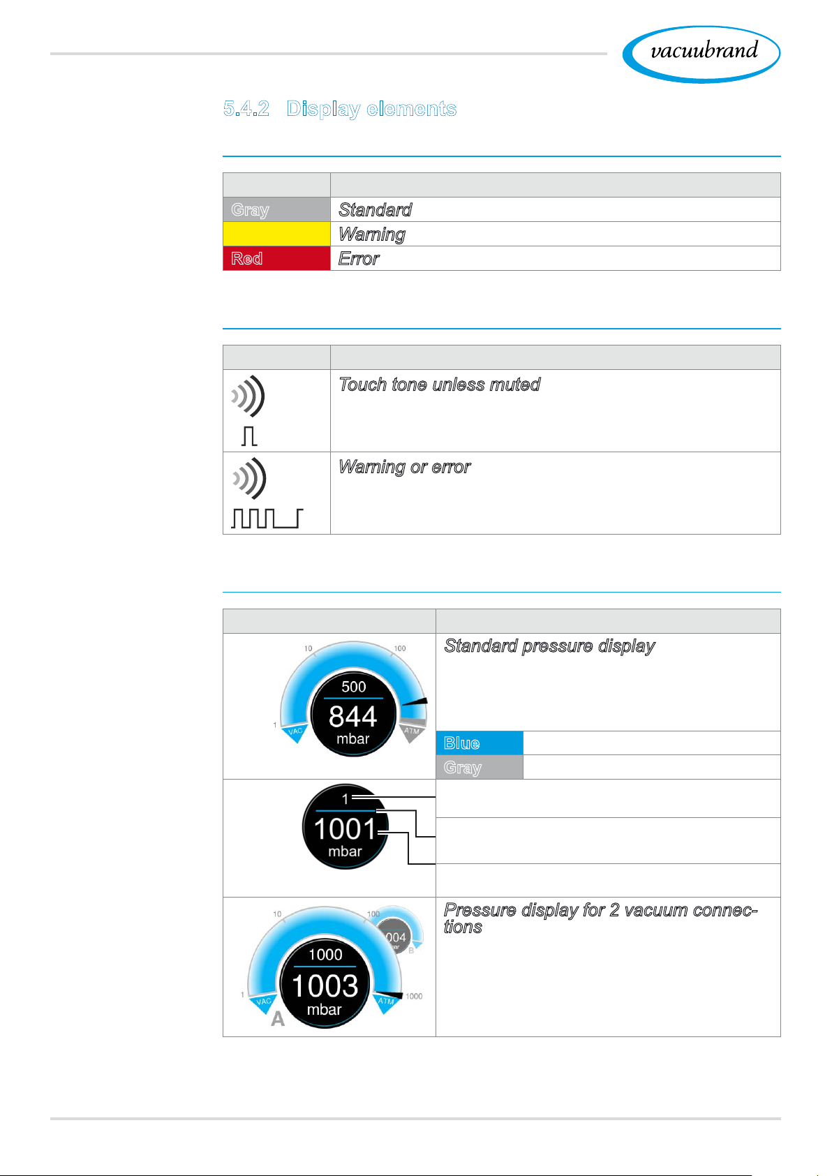
Status bar color
codes
Sounds
Color Meaning
Gray
Yellow
Red
Standard
Warning
Error
Sounds
Sound Meaning
Touch tone unless muted
Feedback entry
Warning or error
Shows that an error or warning is present.
Active while error status persists.
Pressure display
Example
Standard pressure
display
Example
Pressure display
PC 520, PC 620
Symbol (icon) Meaning
Standard pressure display
Pressure curve – analog pressure dis‑
play.
Digital pressure display.
Blue
Gray
Pressure setpoint
Blue dividing line – animated during op‑
eration
Actual pressure and pressure unit
Pressure display for 2 vacuum connections
Analog and digital pressure display for
2 processes (A + B).
Switch between the processes by tap‑
ping the symbol.
Actual pressure
Control range
42 20901059_EN_VACUU·SELECT_V1.3_280119
Page 43
Pop‑up windows (context menus)
User interface
Examples
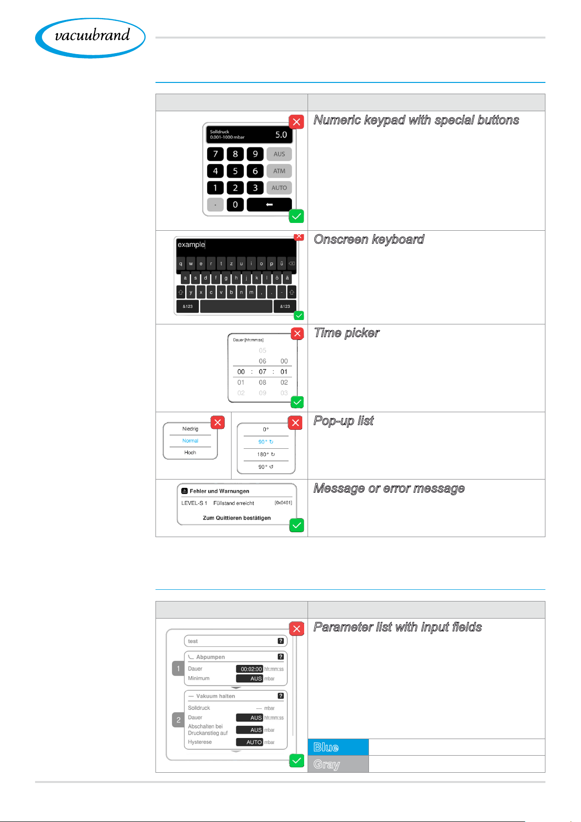
Pop‑up window
Graphic Function
Numeric keypad with special buttons
Enter numerical values.
Select a function using special buttons
(OFF, ATM, AUTO).
Min./max. values displayed.
Values outside the permissible input
range are not accepted.
Onscreen keyboard
Enter alphanumeric values in the input
eld.
Automatic switching between
QUERTY or QUERTZ.
Time picker
Adjust the time by scrolling through
the numbers.
Example
Parameter list
Pop-up list
Select a function or setting.
Message or error message
Message, error message as plain text.
Conrm message, acknowledge error.
Parameter list
Graphic Function
Parameterlistwithinputelds
Display and adjustment of application
values.
Display is divided into process steps.
The parameter list display changes to
reect the selected application.
Blue
Gray
Active process step
Non‑active process step
4320901059_EN_VACUU·SELECT_V1.3_280119
Page 44
User interface
5.4.3 Operating elements and symbols
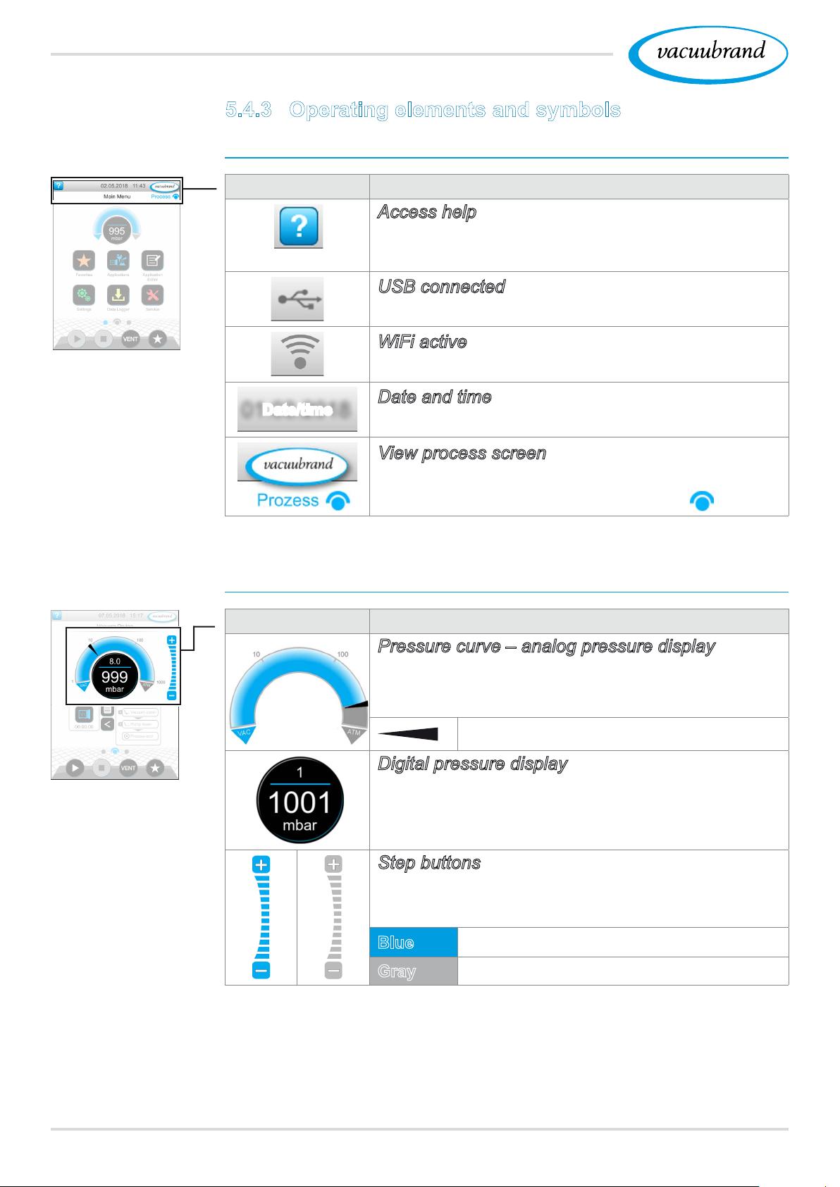
Status bar
Symbol (icon) Meaning
Access help
Tips for operation can be accessed from any
menu level.
USB connected
Shows that a device is connected via USB.
WiFi active (option)
Example
Main menu
Shows that a WiFi USB dongle is inserted.
Date and time
Date/time
Shows the date and time in the preset format.
View process screen
Switch back to the process screen from any
menu level; process screen symbol:
Operating elements – adjust pressure setpoint
Symbol (icon) Meaning
Pressure curve – analog pressure display
Adjust the pressure setpoint by moving the
marker.
Marker – pressure setpoint
Digital pressure display
Process screen,
adjust pressure
setpoint, even
during operation
Adjust the pressure setpoint by tapping.
Step buttons (not a slider!)
Adjust the pressure setpoint by tapping.
Blue
Gray
44 20901059_EN_VACUU·SELECT_V1.3_280119
Active
Locked
Page 45
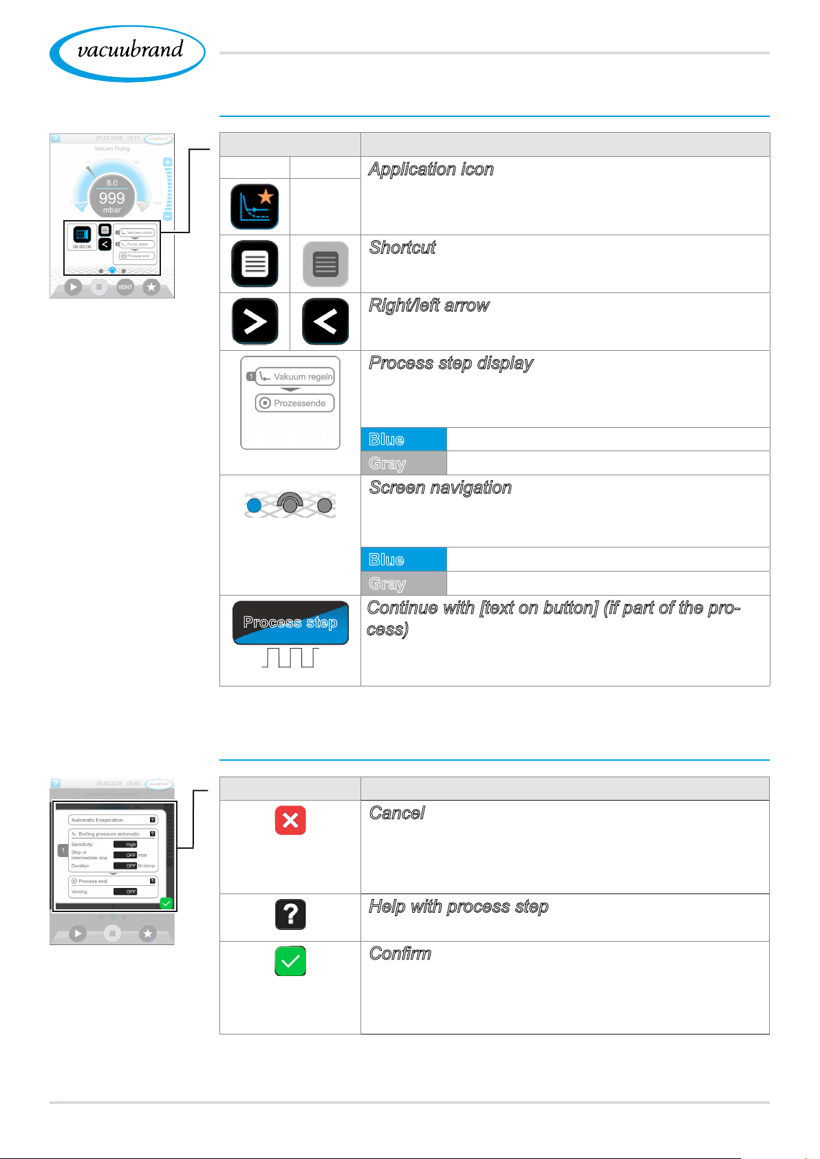
Operating elements – process steps
Button or icon Meaning
Active Locked
Application icon
Tap briey to open the parameter list.
Press and hold to open the context menu.
Shortcut
Open the applications menu.
User interface
Process screen
Process step
Right/left arrow
Open/close the process step display.
Process step display
View the parameter list.
Process step display.
Blue
Gray
Active process step during operation
Non‑active process step
Screen navigation
Switch between the screens of a menu level.
Blue
Gray
Selected page
Additional pages in the level
Continue with [text on button] (if part of the process)
By tapping on the button, start the next process
step shown, e.g., hold vacuum.
Example
Parameter list
Operating elements – parameter list
Symbol (icon) Meaning
Cancel
Cancel entry or selection.
Go back to the previous display.
Exit the menu.
Help with process step
Display information about the process step.
Conrm
Conrm entry or selection.
Exit the menu.
Acknowledge an error.
4520901059_EN_VACUU·SELECT_V1.3_280119
Page 46
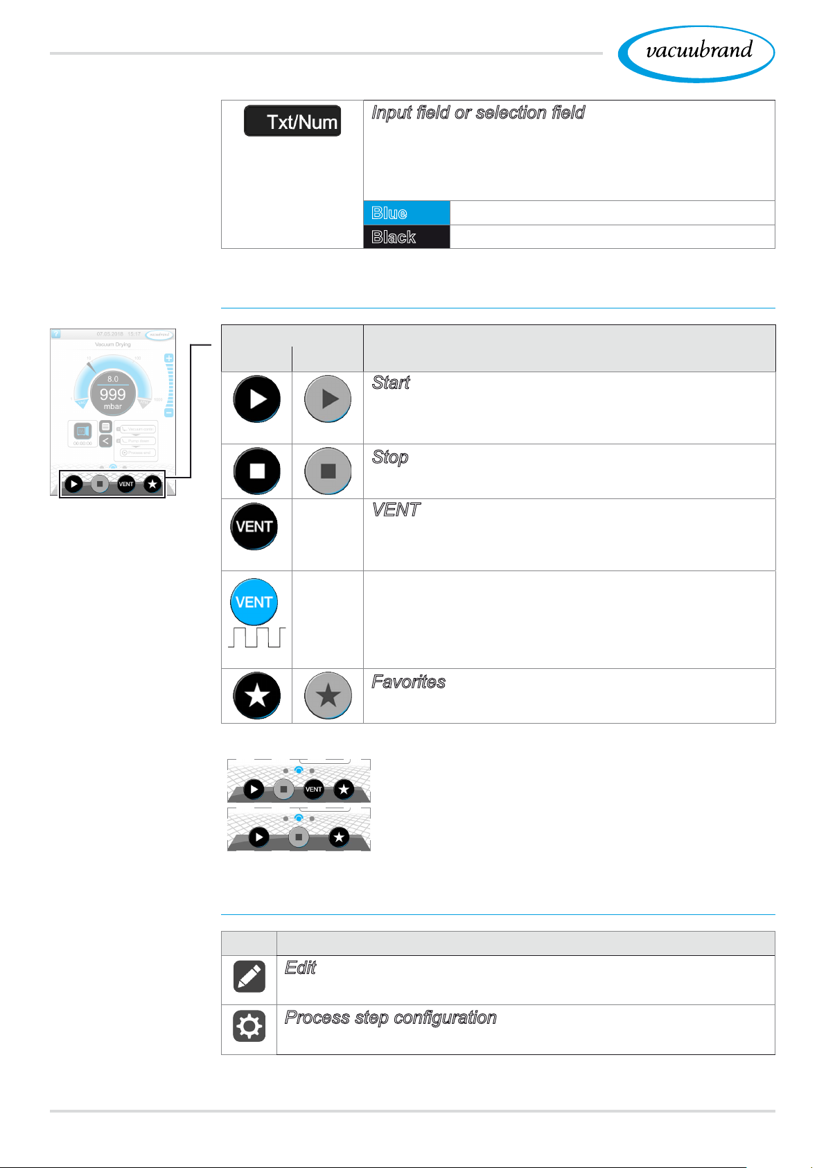
User interface
Parameter list
Process screen
Inputeldorselectioneld
Tap to open a pop‑up window where you can
enter values or select a function, even during
operation.
Blue
Black
Input eld for active process
Input eld for inactive process
Operating elements for control
Button
Active Locked
*
Function
Start
Start application – only available on the process
screen.
Stop
Stop application – always possible.
VENT – vent the system (option)
Press button < 2 sec = vent briey; control con‑
tinues.
*
Press button > 2 sec = vent to atmospheric
pressure; vacuum pump is stopped.
Press button during venting = venting is
stopped.
Favorites
View Favorites menu.
* Button is only displayed if venting valve is connected or activated.
= venting valve connected and activated
= no venting valve connected or deactivated
Other icons and their functions
Icon Meaning
Edit
Enter description for new application in application editor
Processstepconguration
Adjust process step details in application editor.
46 20901059_EN_VACUU·SELECT_V1.3_280119
Page 47
Operation
6 Operation
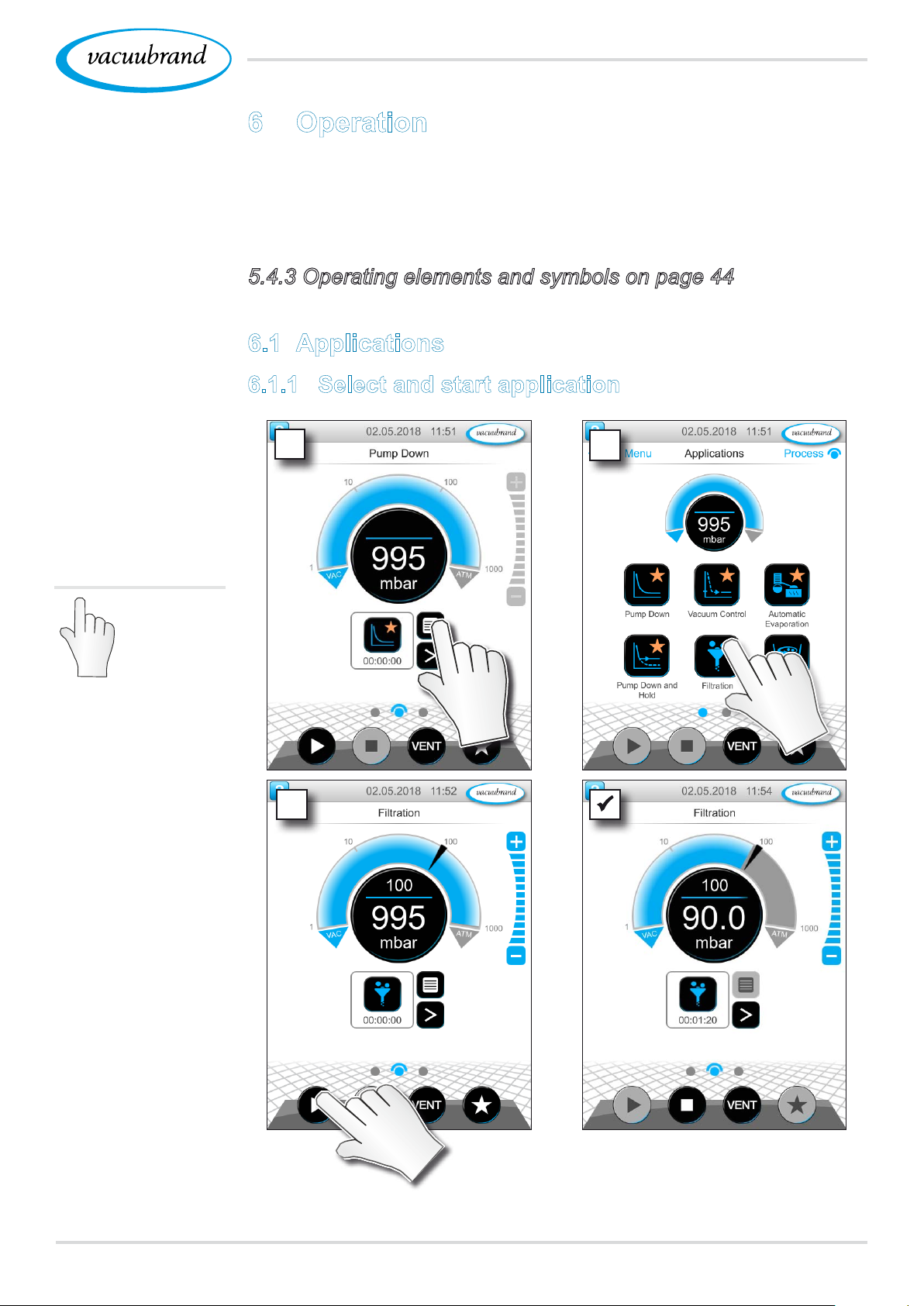
The controller has an application‑based user interface. You can
select, edit and start an application from a series of pre‑dened
basic applications. Fine adjustments for the selected application
can be made at any time in the parameter list or directly via the
5.4.3 Operating elements and symbols on page 44.
6.1 Applications
6.1.1 Select and start application
Example
Select and start
application
Tap/press
lightly
1
3
2
5 Vacuum control running.
5 Animated blue dividing line.
4720901059_EN_VACUU·SELECT_V1.3_280119
Page 48
Operation
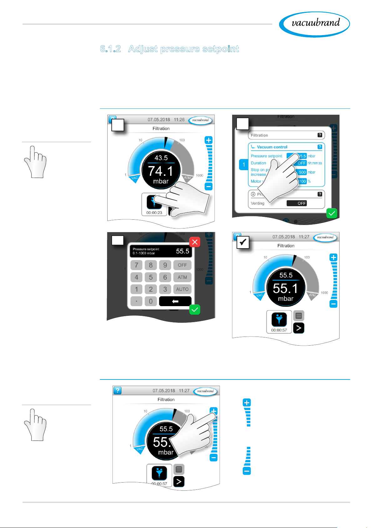
6.1.2 Adjust pressure setpoint
The controller offers a variety of options for adjusting the pres‑
sure setpoint during operation.
Change pressure setpoint in the parameter list
Tap/press
lightly
1
3
2
Enter a target value in the
pop‑up and conrm the entry
2x.
Fine adjustment via step buttons
Tap/press
lightly
‑ Tap or hold down but‑
tons = increase target
value
‑ Tap or hold down but‑
tons = decrease target
value
48 20901059_EN_VACUU·SELECT_V1.3_280119
Page 49
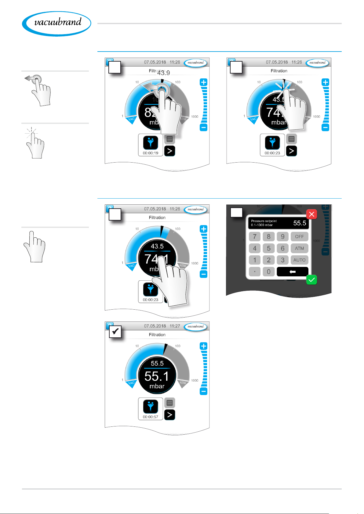
Hold
down
and drag
Release
Operation
Adjust pressure setpoint using marker
1 2
Adjust pressure setpoint in digital pressure display
Tap/press
lightly
1
2
Enter a target value in the
pop‑up and conrm the entry.
4920901059_EN_VACUU·SELECT_V1.3_280119
Page 50
Operation
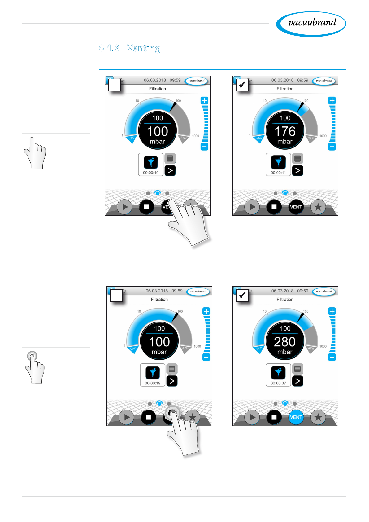
6.1.3 Venting
Vent briey
Brief venting
Tap/press
lightly
5 Slight pressure increase.
5 Vacuum control running.
Continuous venting
Hold down
Vent to atmospheric pressure
~ 3 sec
5 Vacuum control stops.
5 Pressure increase until
atmospheric pressure is
reached.
50 20901059_EN_VACUU·SELECT_V1.3_280119
Page 51
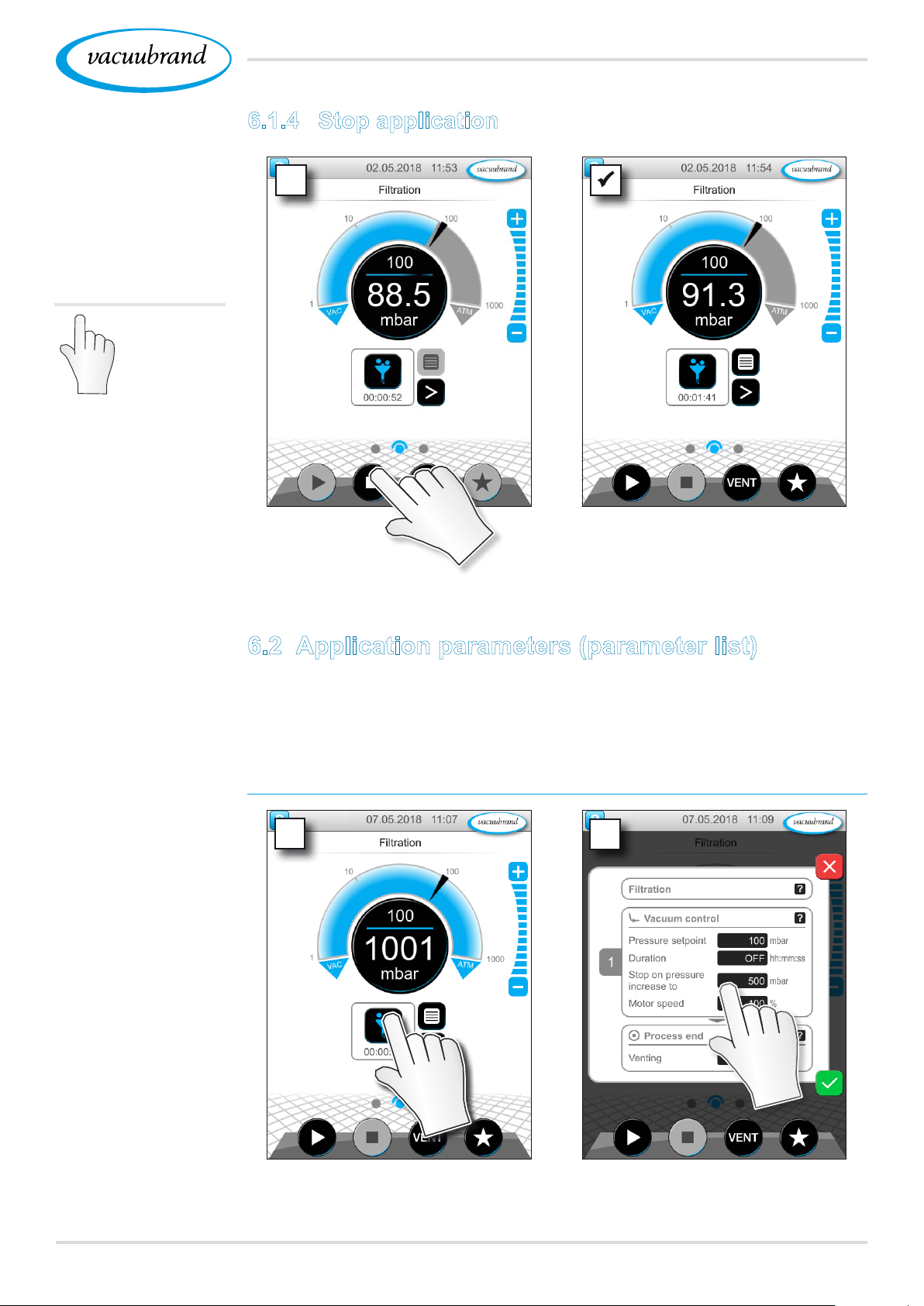
6.1.4 Stop application
Operation
Stop application
Tap/press
lightly
5 Vacuum control stops.
Example
Adjust motor speed
6.2 Application parameters (parameter list)
In the parameter list, you can individually change and adapt vari‑
ous process‑related values before and during operation.
Adjust parameter
1
2
1. View parameter list. 2. Tap on desired input eld.
5120901059_EN_VACUU·SELECT_V1.3_280119
Page 52
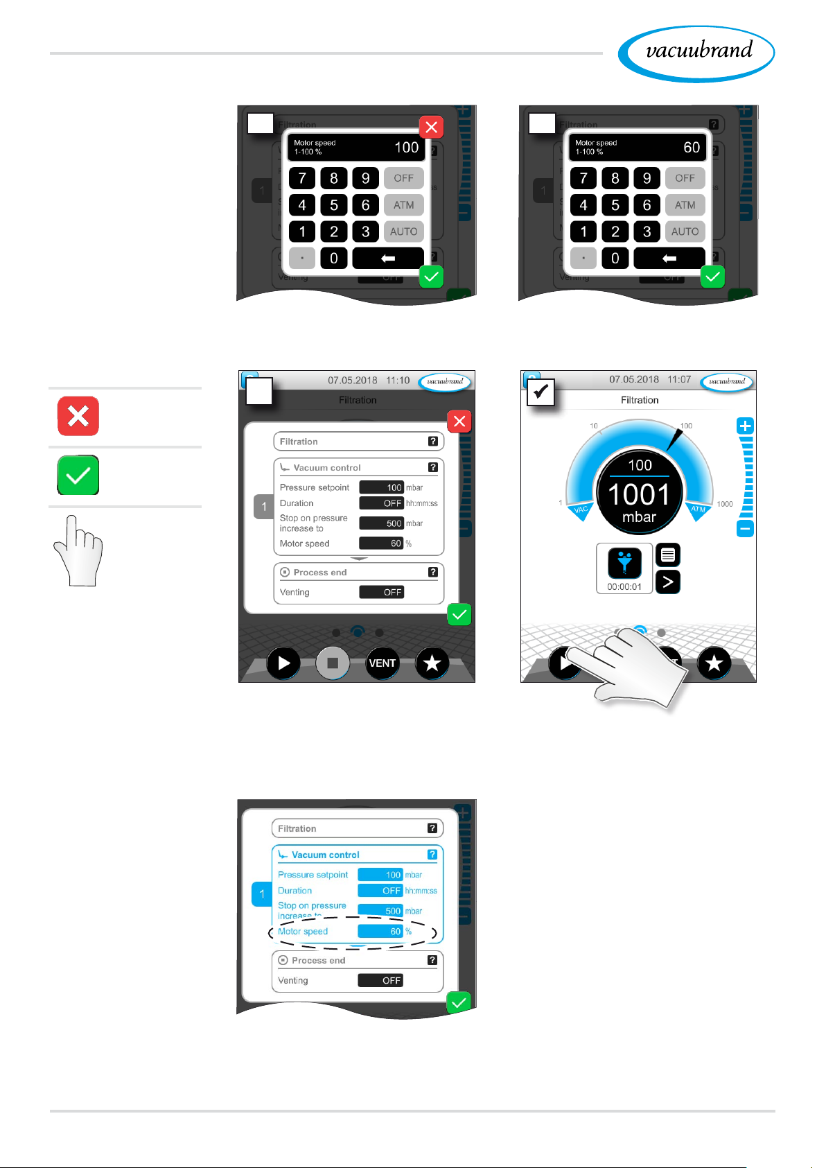
Operation
Example
Adjust motor speed
parameter
Cancel
Conrm
3 4
3. Enter the required motor
speed in the pop‑up.
5
4. Conrm entry.
Tap/press
lightly
Example
View of motor speed
parameter during
operation
5. Conrm the change in the
parameter list.
5 Once the application starts,
the motor runs at the
adjusted speed.
You can make individual
adjustments for your process
in the parameter list at any
time.
52 20901059_EN_VACUU·SELECT_V1.3_280119
Page 53
Operation
6.3 Pressure graph
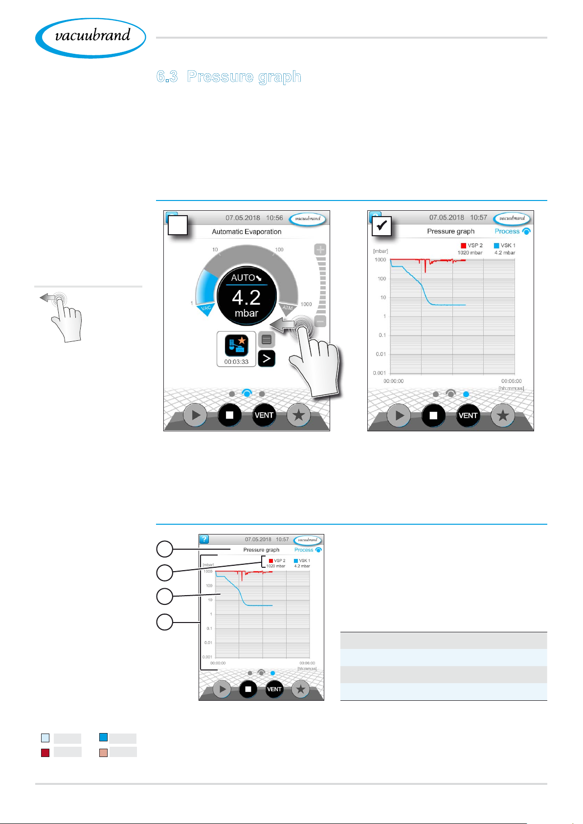
The pressure graph is on the same level as the process screen.
The menu shows pressure curves of measured vacuum values.
The pressure curve is shown until a new application is started, at
which point it is replotted.
View pressure curve
Example
View pressure graph
Swipe
left
Swipe left on the display.
5 Pressure graph display.
5 Measurement curves of
connected vacuum sensors.
VSK1
VSP2
VSK1
VSP2
Pressure graph display
1
2
3
4
1
Menu name
2
Key to colors
3
Measurement curve(s)
4
Pressure/time graph
Tap on the color key of a vacuum sensor to display or hide indi‑
vidual measurement curves.
5320901059_EN_VACUU·SELECT_V1.3_280119
Page 54
Operation
6.4 Main menu
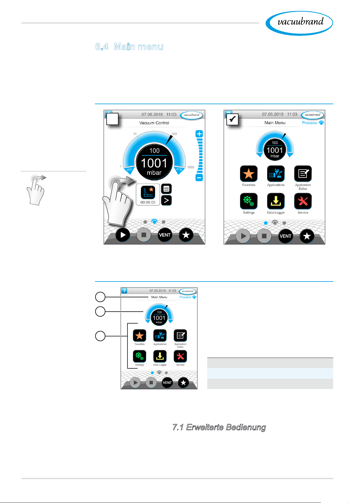
The main menu is on the same level as the process screen. The
submenus of the controller can be accessed from the main menu.
View main menu
Example
View main menu
Swipe
right
Swipe right on the display.
Main menu display
5 Main menu display.
1
2
3
1
Menu name
2
Pressure display
3
Overview of submenus
The function of each submenu is shown by its icon and the text
below it.
See also chapter: 7.1 Erweiterte Bedienung
54 20901059_EN_VACUU·SELECT_V1.3_280119
Page 55
Operation
6.4.1 Applications
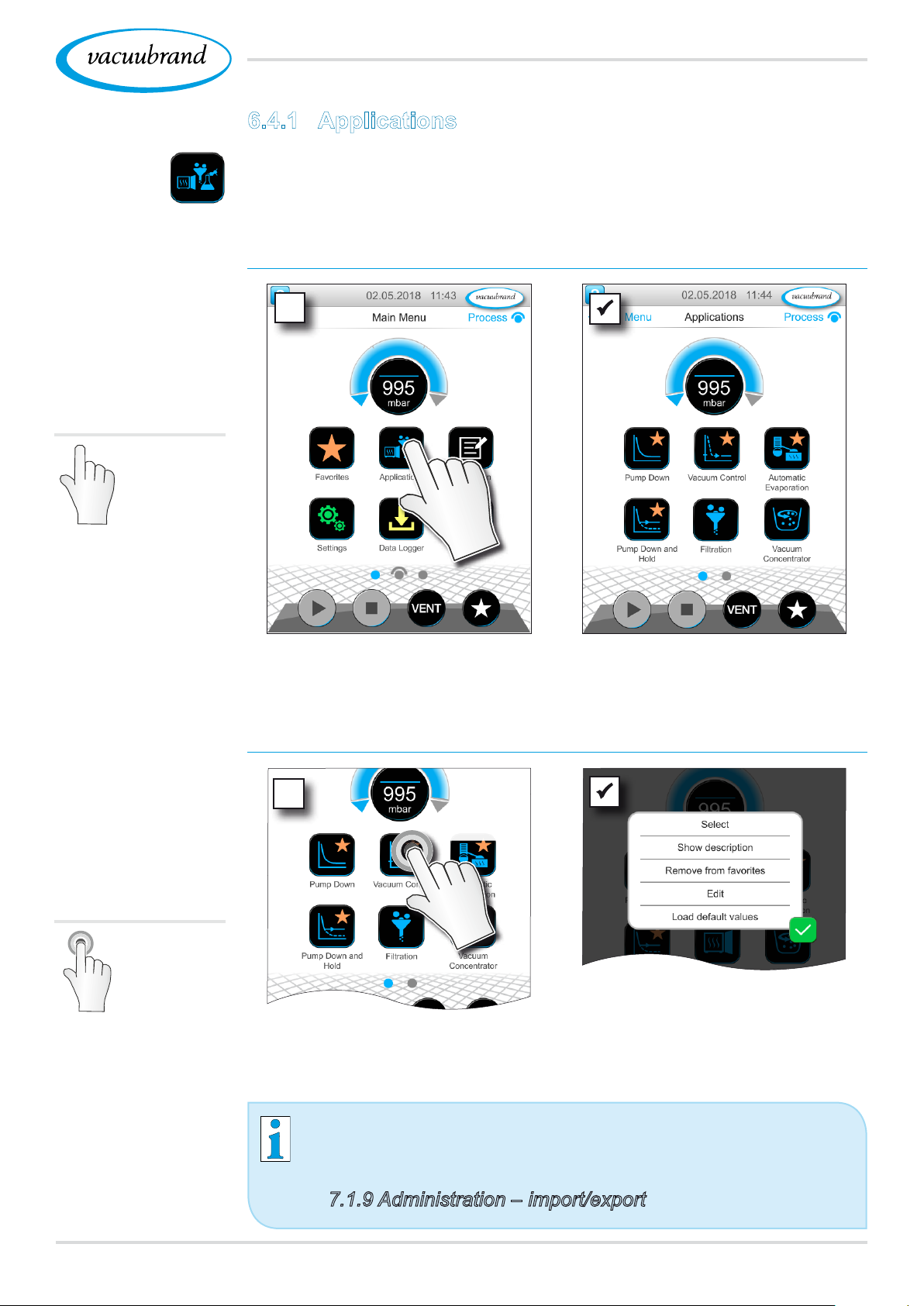
This menu lists all applications: default application, favorites, and
newly created applications.
View application menu
View applications
submenu
Tap/press
lightly
Show context menu
5 Display the applications
submenu.
Example
View context menu
for applications
Hold down
~ 3 sec
5 The context menu
appears.
Select the required function in the context menu.
Would you like to transfer your applications to another
VACUU·SELECT?
Simply use the export function as described in chapter:
7.1.9 Administration – import/export
5520901059_EN_VACUU·SELECT_V1.3_280119
Page 56
Operation
6.4.2 Favorites
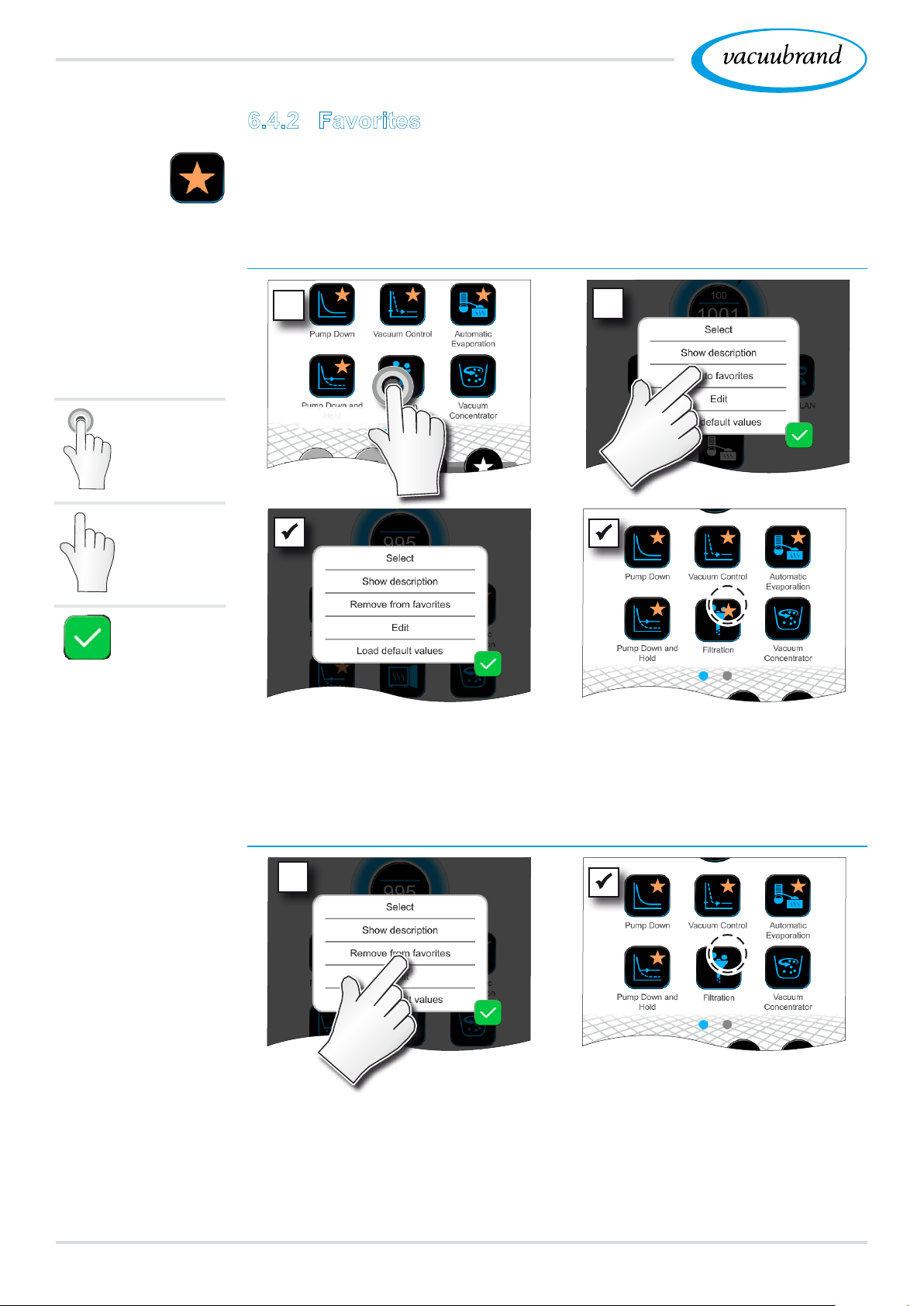
Applications marked as favorites are identied by a star on the
button.
Add favorites
Example
Add favorites
Hold down
Tap/press
lightly
Conrm
1
~ 3 sec
5 Text changed in the con‑
text menu.
2
5 Button with favorites star.
5 Application listed in favor‑
ites menu.
Remove favorites
Example
Remove favorites
56 20901059_EN_VACUU·SELECT_V1.3_280119
View the context menu.
Tap Remove from favorites
and conrm.
5 Button without favorites
star.
5 Application removed from
favorites menu.
Page 57

Main menu
7 Main menu
7.1 Advanced operation
7.1.1 Application editor
In the application editor, you can compile your own application
using the building‑block principle and save it with an appropriate
name.
Existing applications can be used in the application editor as tem‑
plates, and then saved with a new name.
In the case of lengthy applications, you can scroll through the
overview of the process steps.
Example
View application
editor
Tap/press
lightly
View application editor
5720901059_EN_VACUU·SELECT_V1.3_280119
Page 58
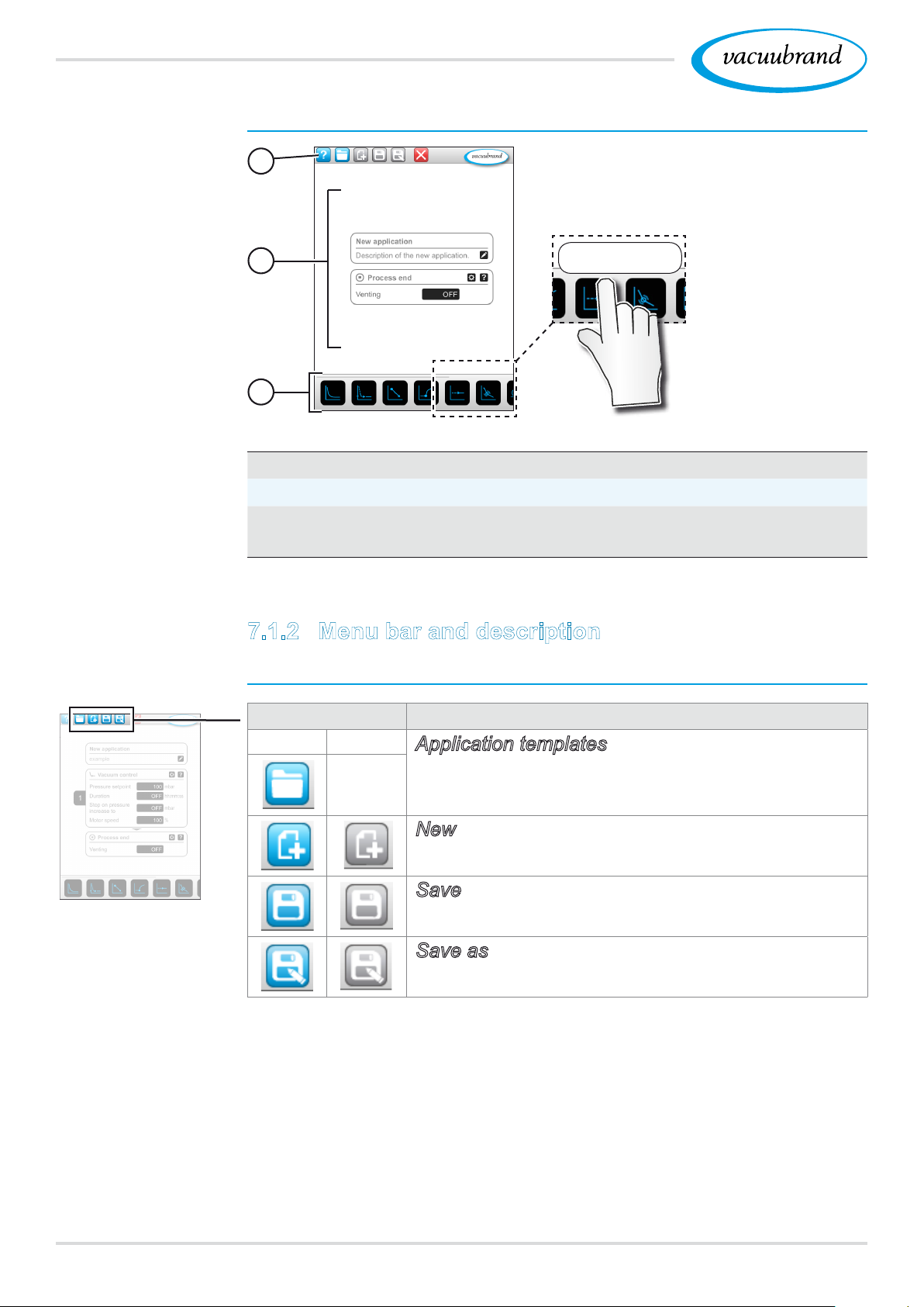
Main menu
Application editor display
1
2
3
1
Menu bar
2
Overview of process steps
3
Building blocks with individual process steps which you can
Hold vacuum
scroll through and select as required.
7.1.2 Menu bar and description
Menu bar
Tool tips help
when selecting
process steps.
Example:
Application editor
Icon buttons Meaning
Active Locked
‑ ‑ ‑
Application templates
Search for an application for editing from a
series of existing applications.
New
Create a new application.
Save
Save application.
Save as
Name of the application.
58 20901059_EN_VACUU·SELECT_V1.3_280119
Page 59
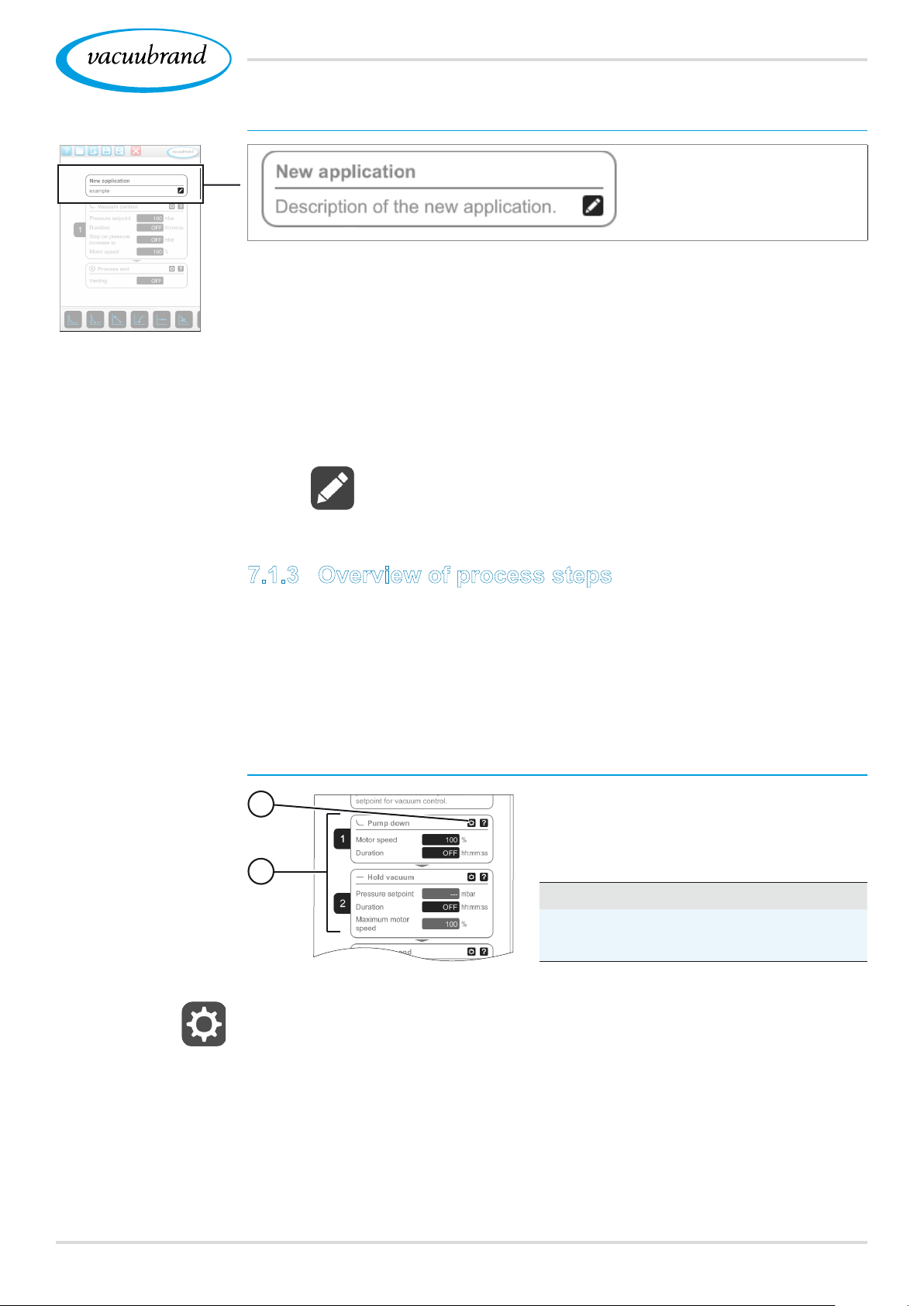
Example:
Application editor
Main menu
Description of the application
New application: this name is automatically changed as soon
as you give your application an appropriate name using Save as.
Description of the new application: here, you can enter a brief
description of your application. This description appears later in
the parameter list. Custom descriptions are only shown in the
creator's language.
Open the context menu to enter a description by tapping
on:
Example
Process step
sections
7.1.3 Overview of process steps
Individual process steps can be added or removed by dragging
and dropping. If a process step is dragged onto the editor screen,
the image changes. The process step is shown as a numbered
process step section.
Meaning of process step section(s)
1
2
1
Process step conguration
2
Process step section, num‑
bered.
Using the process step conguration, you can specify which
parameters will later be displayed in the parameter list and which
are available for editing.
Each process step section represents a process step. By hold‑
ing down and moving the numbers, process step sections can be
(re)arranged as desired.
As a visual aid to help you rearrange the process step sections, a
blue bar appears at the point where they can be placed.
5920901059_EN_VACUU·SELECT_V1.3_280119
Page 60
Main menu
The process step sections are numbered from top to bottom,
from 1 to n. If a process step section is added, shifted or removed,
the numbering is adjusted automatically.
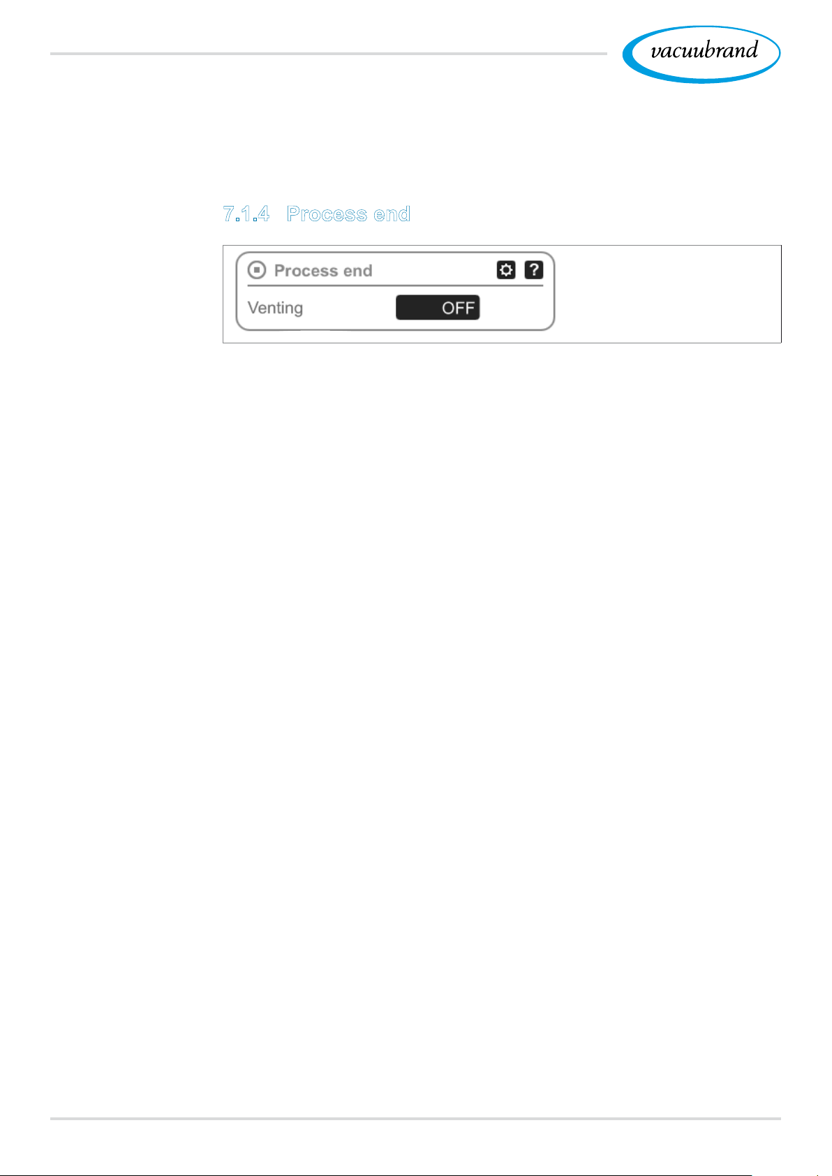
7.1.4 Process end
Process end means the dened end of an application. Process
steps can only be placed above this.
60 20901059_EN_VACUU·SELECT_V1.3_280119
Page 61
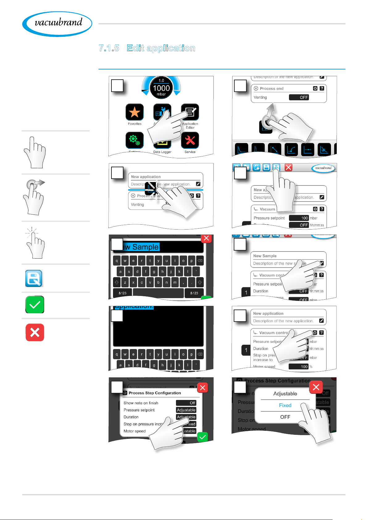
Example
Create a new
application
Tap/press
lightly
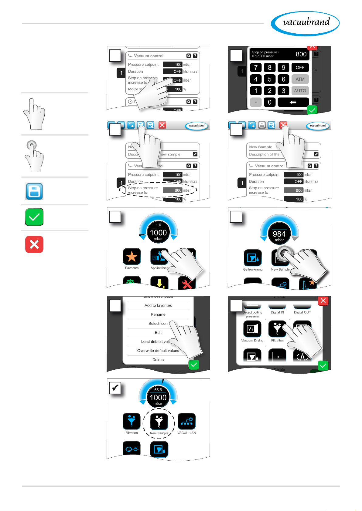
7.1.5 Edit application
Create a new application
1
Main menu
2
Hold down
and drag
Release
Save as
Conrm
Exit menu
3
5 6
7 8
4
9 10
6120901059_EN_VACUU·SELECT_V1.3_280119
Page 62
Main menu
Example
Edit new application
Tap/press
lightly
Hold down
Save
11 12
13 14
Conrm
Exit menu
15
16
17 18
5 New application listed with
white symbol in applications
submenu.
62 20901059_EN_VACUU·SELECT_V1.3_280119
Page 63
Example
Edit existing
application
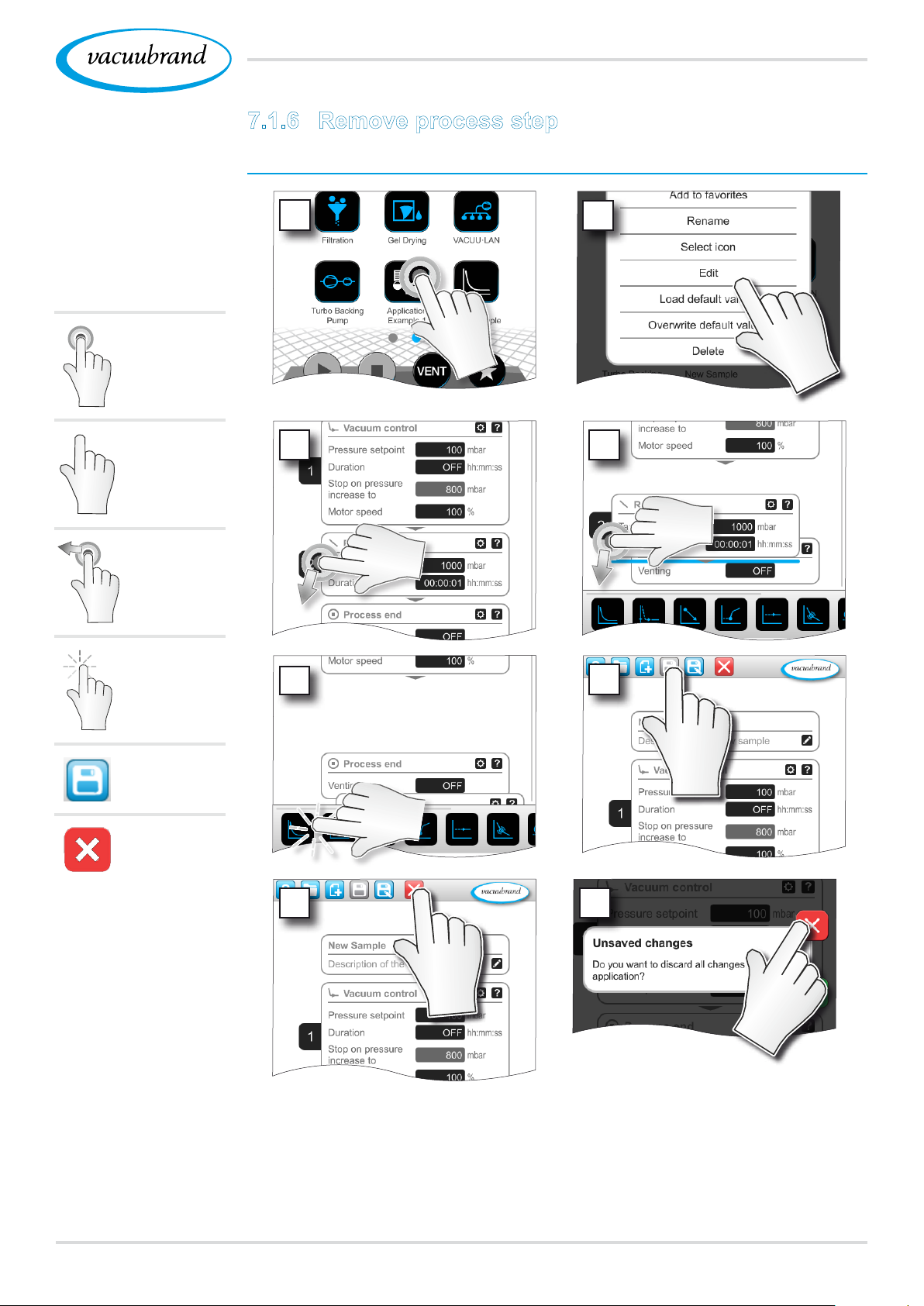
Hold down
Tap/press
lightly
7.1.6 Remove process step
Change application
1
3 4
Main menu
2
Hold down
and drag
Release
Save
Exit menu
5
7 8
6
5 The removed process step is no longer displayed in the
parameter list of the application.
6320901059_EN_VACUU·SELECT_V1.3_280119
Page 64
Main menu
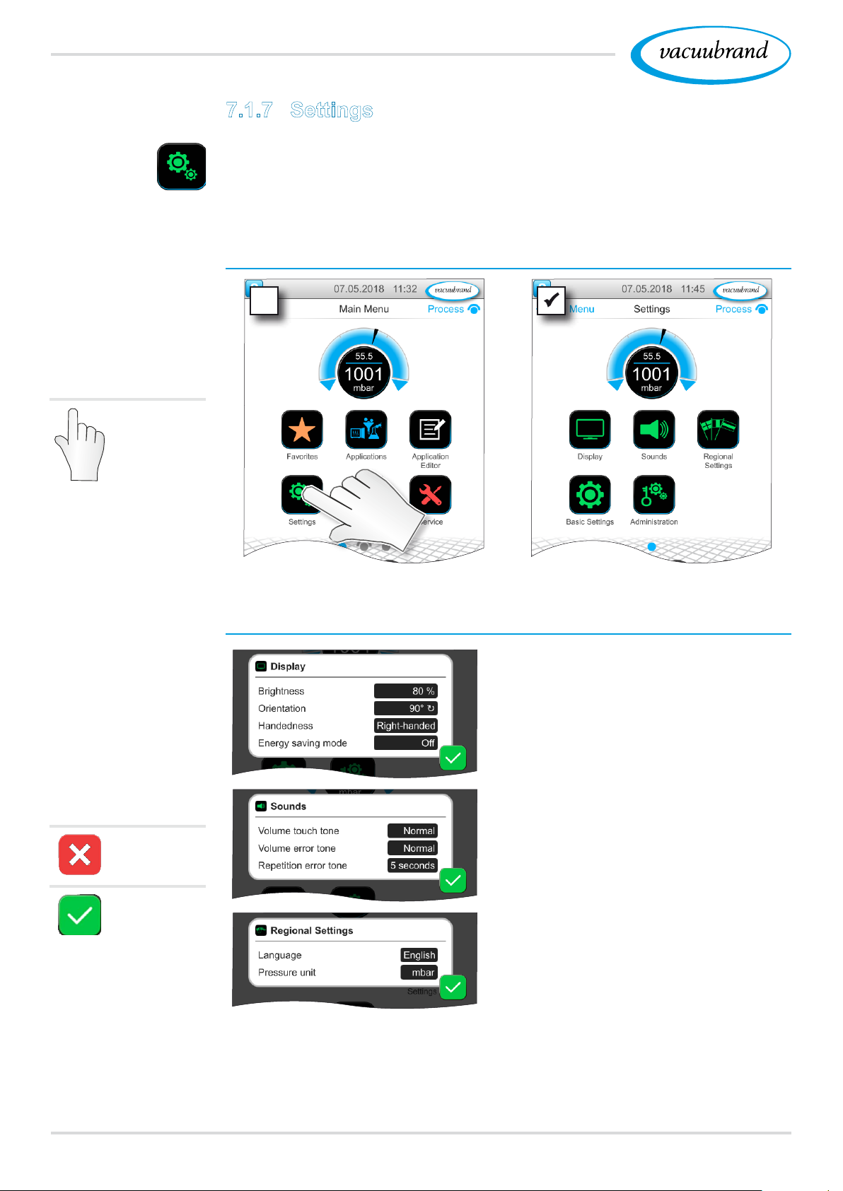
7.1.7 Settings
In this submenu you can adjust the display, switch to another
language, and make presettings for connected VACUU·BUS pe‑
ripheral devices.
View settings submenu
Example
Main menu \
Settings \ Basic
settings
Tap/press
lightly
Example
Overview
Context menu
settings
Meaning of the context menu
Under Display, you can change
settings for the screen.
Under Sounds, the volume of the
acoustic signals for warnings and
haptics can be set or switched off.
Cancel
Conrm
In Regional Settings, you can
change the language and pressure
unit.
64 20901059_EN_VACUU·SELECT_V1.3_280119
Page 65
Main menu
Example
Overview
Context menu
settings
Overview of
possible basic
settings
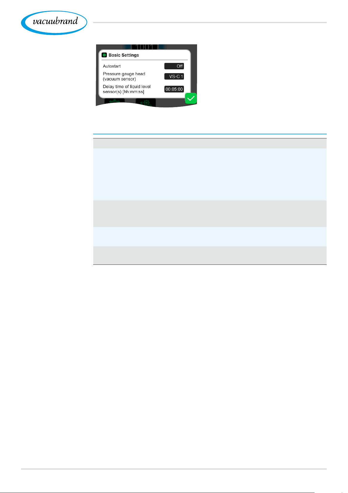
You can specify presettings for your
process in Basic Settings. The
vacuum sensor, which measures
actual pressure, is shown here.
Meaning of basic settings
Function Setting Meaning
Autostart Off / On Off: The controller is set to
"stop" after power is restored.
On: An application that was
started is continued following a
power failure and subsequent
restoration of power.
Vacuum sensor VS‑C _ / VS‑P _ Select the vacuum sensor for
control. VSK: rough vacuum,
VSP: ne vacuum.
Run‑on time for cool‑
ant valve(s)
Off / hh:mm:ss Coolant run‑on time.
Delay time for level
sensor(s)
Off / hh:mm:ss
Delay time for full status indi‑
cator of level sensor.
The available basic settings adapt to the connected VACUU·BUS
components.
6520901059_EN_VACUU·SELECT_V1.3_280119
Page 66
Main menu
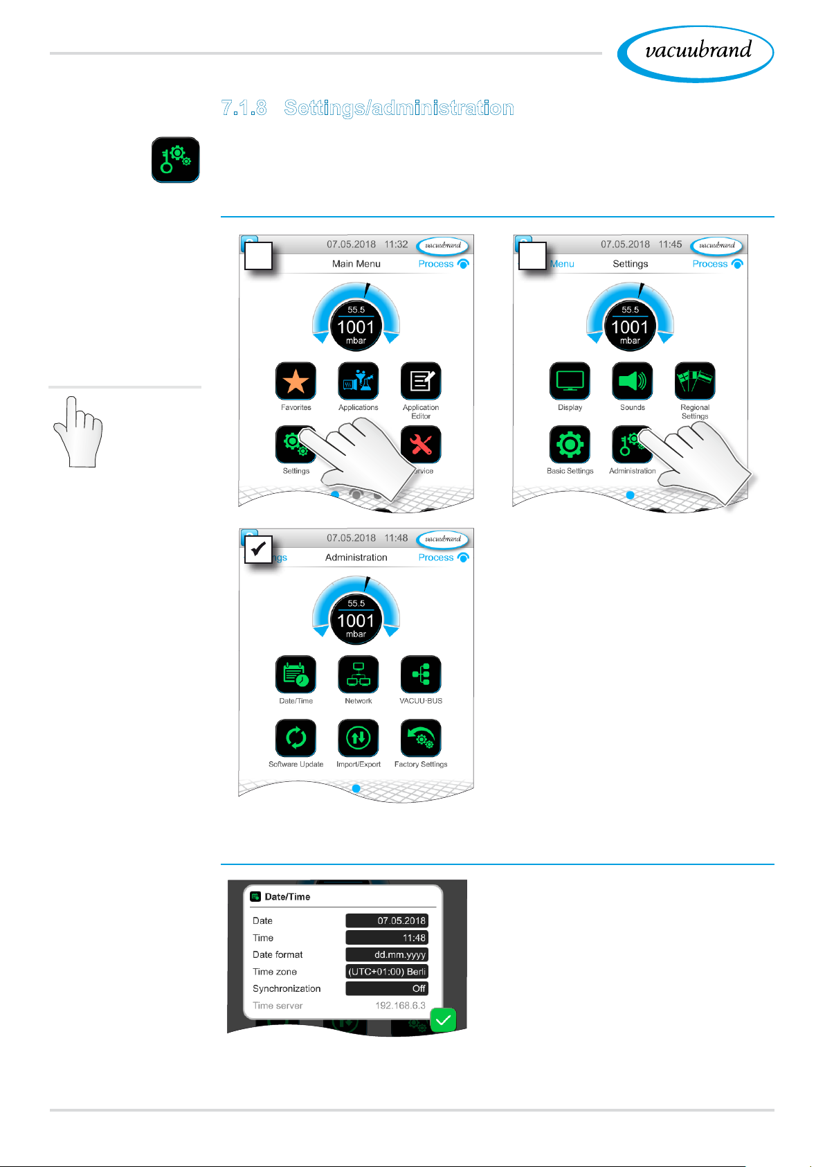
7.1.8 Settings/administration
Administration area of the controller – only for authorized staff.
View administration submenu
Example
Main menu \
Settings \ Adminis‑
tration
Tap/press
lightly
1 2
5 Submenu with buttons for
administrative purposes.
Meaning of the context menu
Example
Overview
Context menu
Administration
66 20901059_EN_VACUU·SELECT_V1.3_280119
Adjustments for date and time.
Page 67
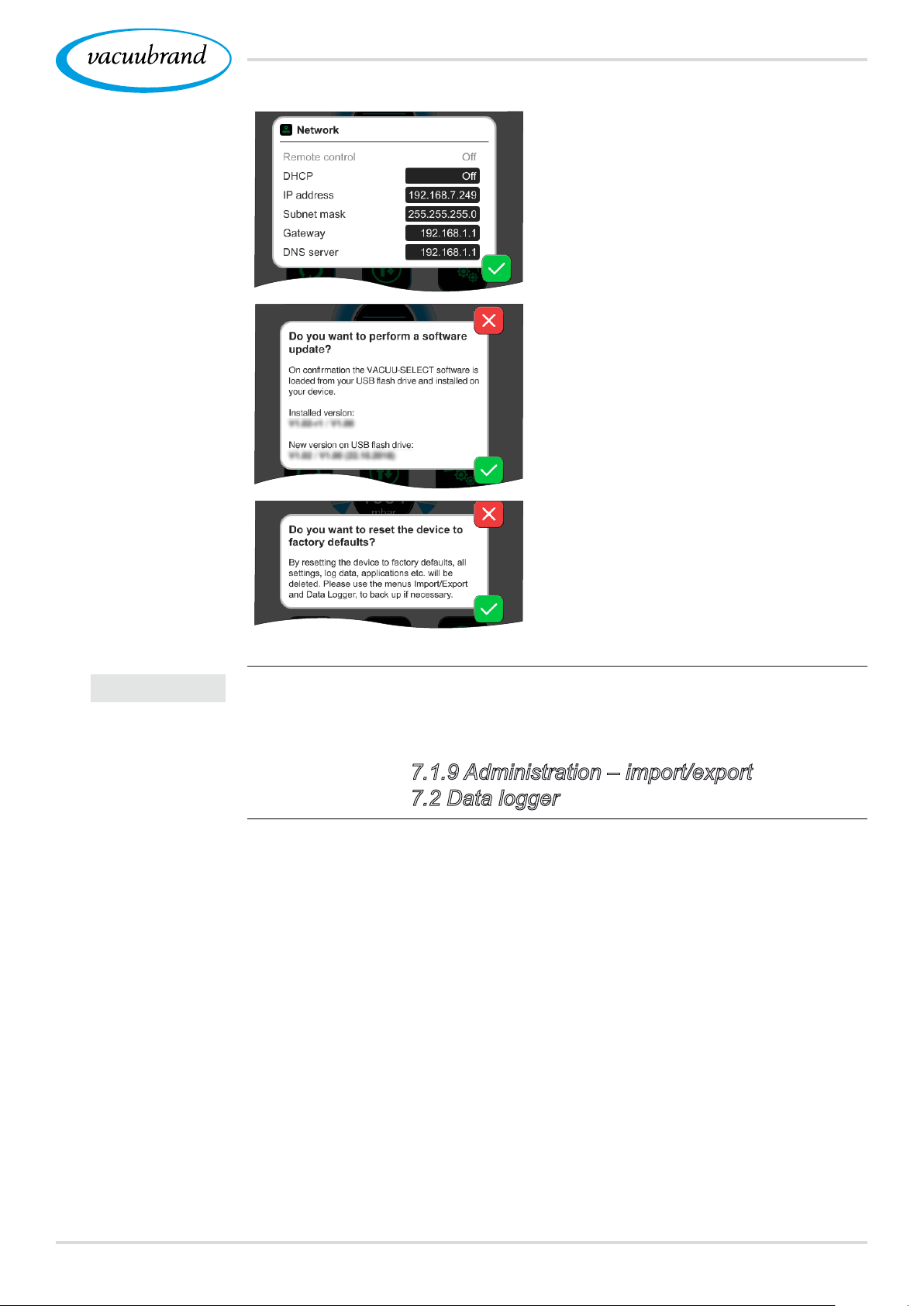
Main menu
Presettings for adding the controller
to your network.
Activate command for loading soft‑
ware update from connected USB
ash drive.
IMPORTANT!
Reset the controller to the factory
settings.
Restoring the factory settings deletes all data, settings and ap‑
plications.
Back up your settings, applications and data beforehand;
see chapters: 7.1.9 Administration – import/export and
7.2 Data logger
6720901059_EN_VACUU·SELECT_V1.3_280119
Page 68
Main menu
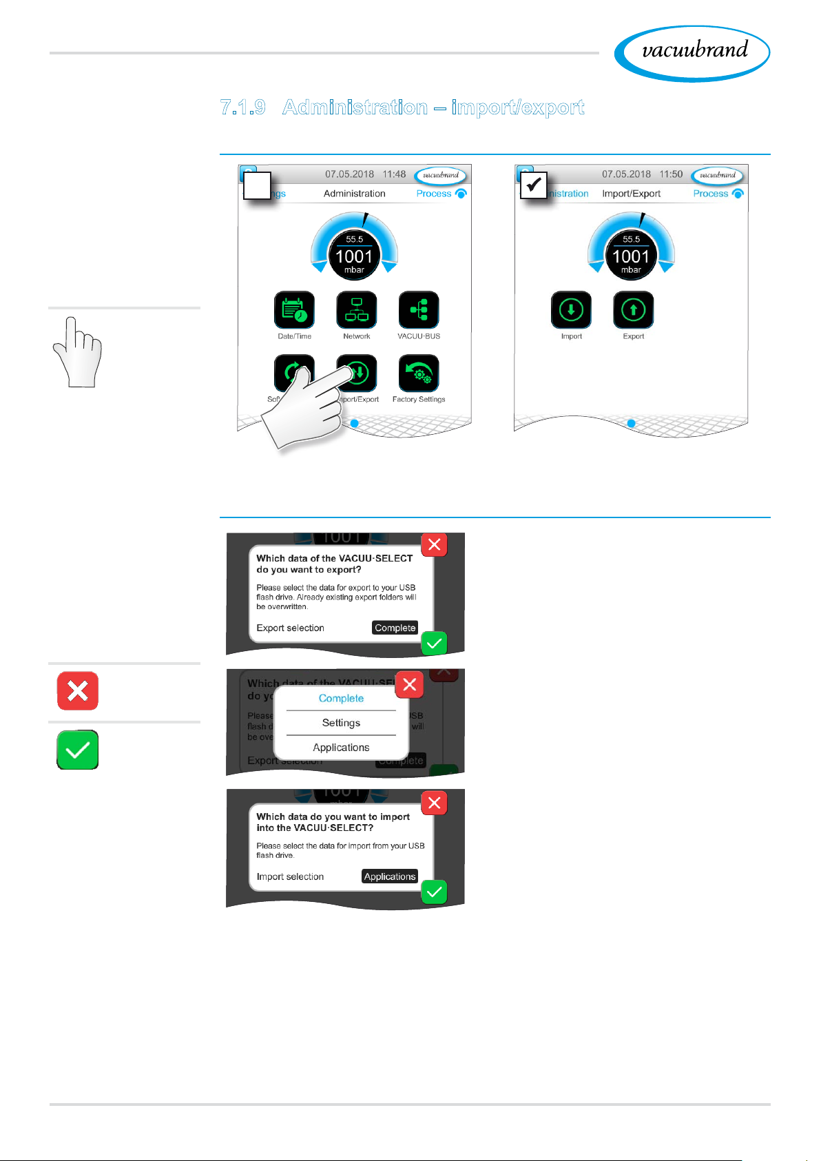
7.1.9 Administration – import/export
View import/export submenu
Example
Main menu \
Settings \ Adminis‑
tration \ Import/
Export
Tap/press
lightly
Example
Overview
Context menu
Import/Export
Meaning of the context menu
You can use the export function to
transfer data, such as applications
you have created, to other control‑
lers via USB ash drive.
Cancel
Conrm
You can customize the data export
by tapping Complete, Settings, or
Applications.
You can use the import function
to transfer data from another exter‑
nal controller to this controller.
68 20901059_EN_VACUU·SELECT_V1.3_280119
Page 69
Main menu
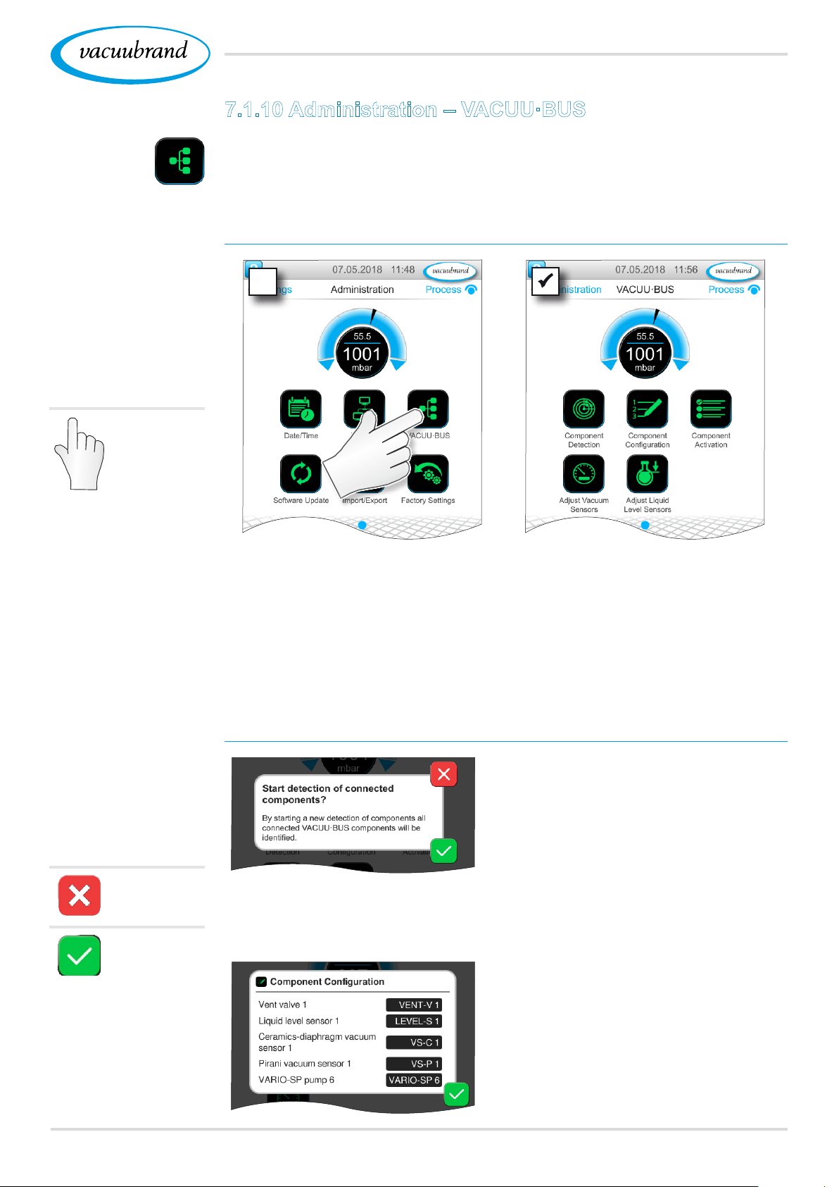
7.1.10 Administration – VACUU·BUS
The VACUU·BUS submenu simplies the detection and manage‑
ment of VACUU·BUS components.
View VACUU·BUS submenu
Example
Main menu
\ Settings \
Administration \
VACUU·BUS
Tap/press
lightly
The buttons retrieve context menus. The context menus facilitate
the use of presettings for VACUU·BUS components, e.g., address
conguration, detection of connected components. Vacuum sen‑
sors and level sensors, amongst others, can be calibrated in this
submenu.
Overview
Context menus
VACUU·BUS
Cancel
Conrm
Meaning of the context menu
The Component detection func‑
tion scans all connected compo‑
nents and updates the list of con‑
nected VACUU·BUS peripherals in
the controller.
Example: If one level sensor is re‑
moved and component detection is
performed, the level sensor will no
longer be listed in the component
conguration.
With component conguration,
the addresses of connected com‑
ponents can be easily changed or
reassigned.
6920901059_EN_VACUU·SELECT_V1.3_280119
Page 70
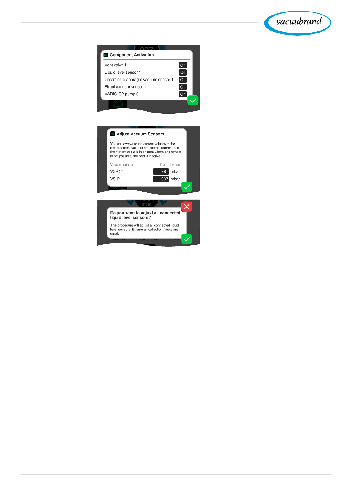
Main menu
Using component activation, con‑
nected VACUU·BUS components
can be individually activated or de‑
activated, i.e., the components can
remain connected but are switched
on or off at the controller as re‑
quired for the ongoing process.
Pop‑up for the calibration of con‑
nected vacuum sensors at ambi‑
ent pressure and under vacuum.
OPTION
Pop‑up for the calibration of con‑
nected level sensors.
70 20901059_EN_VACUU·SELECT_V1.3_280119
Page 71
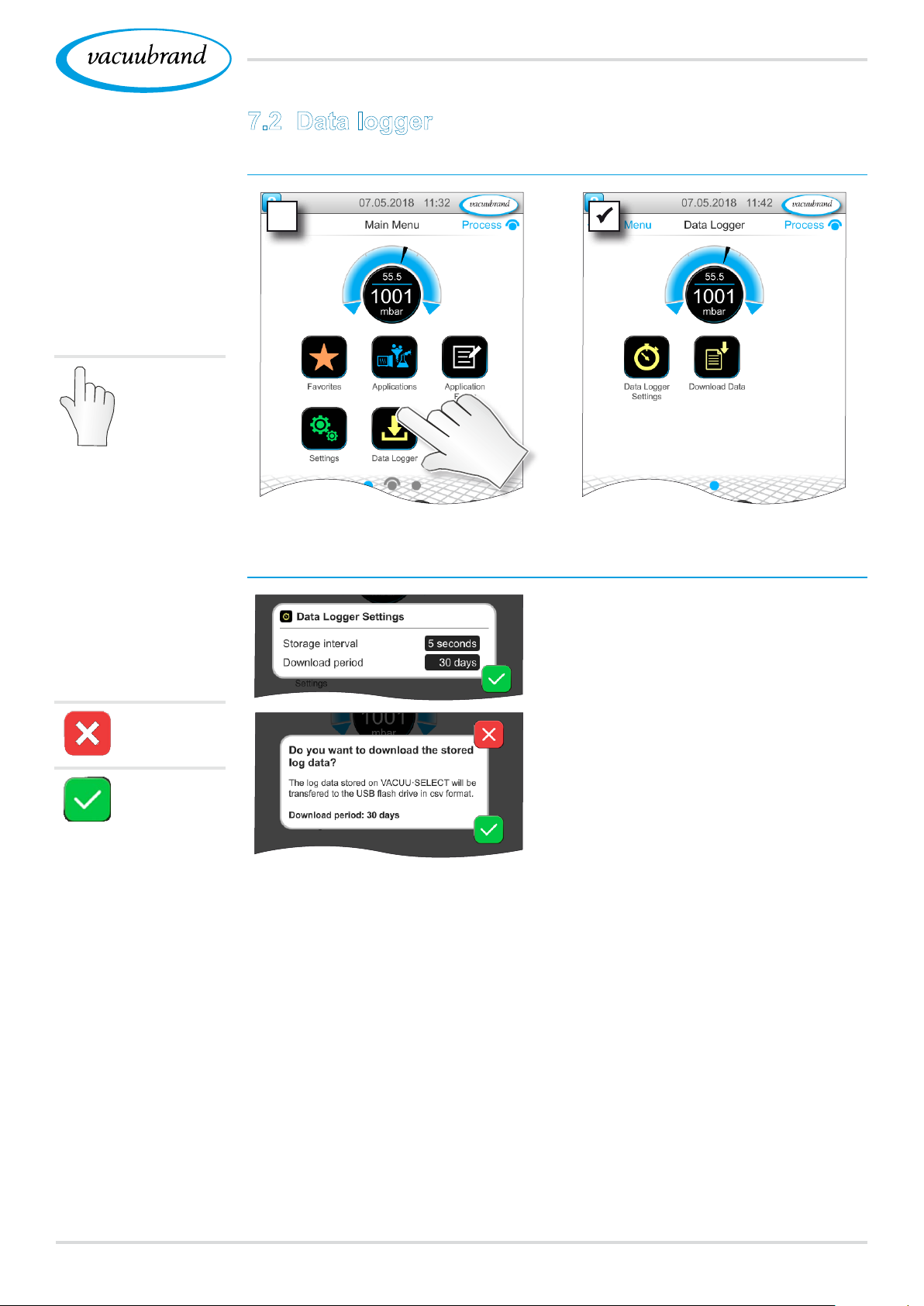
7.2 Data logger
View data logger submenu
Main menu
Example
Main menu \ Data
logger
Tap/press
lightly
Overview
Context menus
Data logger
Meaning of the context menu
In the data logger settings, the
storage interval and download peri‑
od can be specied.
Cancel
Conrm
If a USB ash drive is connected,
the log data for the preset time pe‑
riod can be downloaded here.
7120901059_EN_VACUU·SELECT_V1.3_280119
Page 72
Main menu
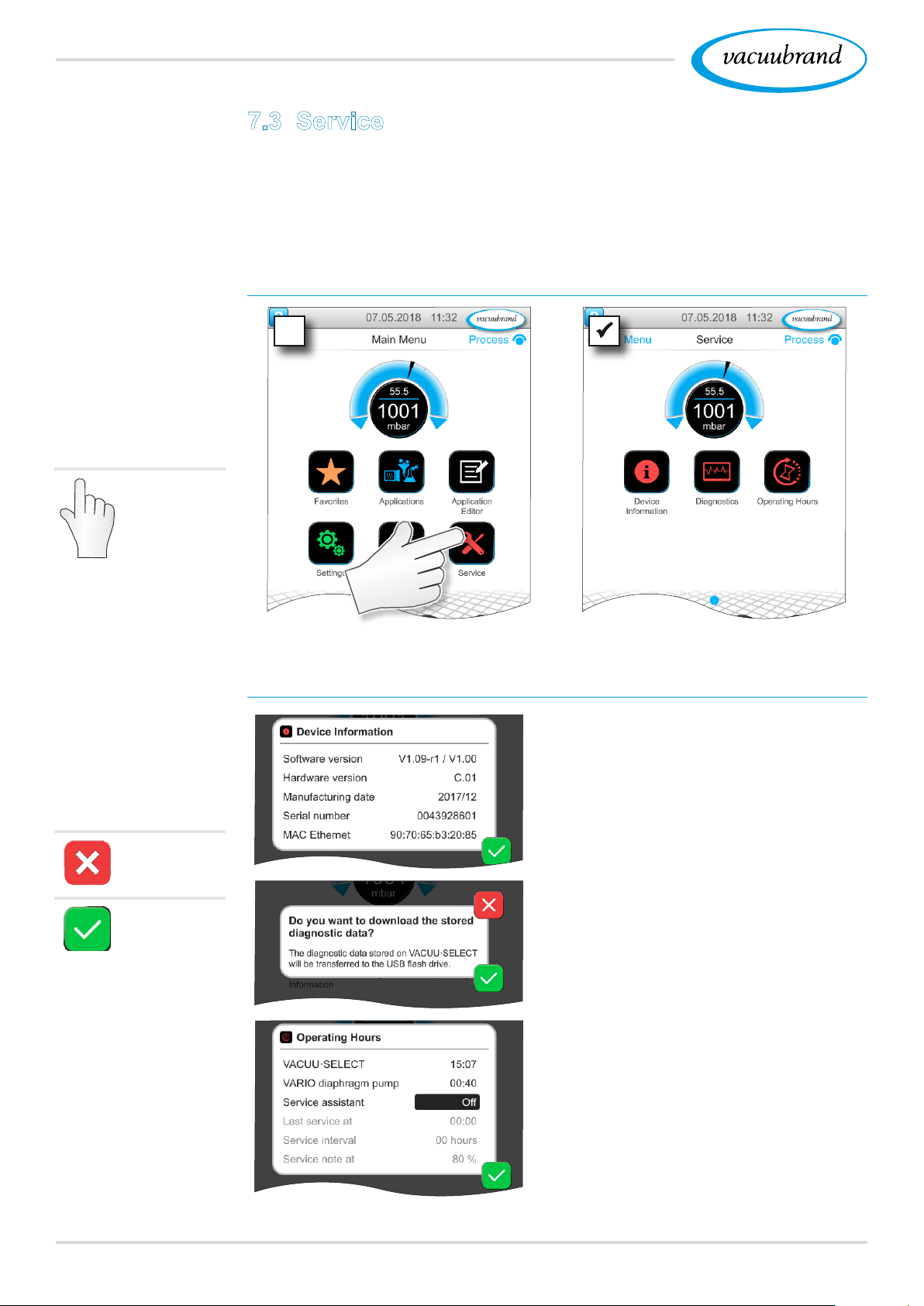
7.3 Service
In this menu, you can nd or download information about the de‑
vice. In the event of an error, please forward this information to
our Service Department.
View service submenu
Example
Main menu \ Service
Tap/press
lightly
Overview
Context menus
Data logger
Meaning of the context menu
Information about the device is
displayed here.
Cancel
If a USB ash drive is connected,
the diagnostics can be download‑
Conrm
. . .
72 20901059_EN_VACUU·SELECT_V1.3_280119
ed here.
Counter for hours of operation
with optional maintenance wizard.
Off: No reminder message.
On: Reminder message for mainte‑
nance after specied hours of
operation have elapsed.
Page 73
8 Troubleshooting
Troubleshooting
Technical support
Example
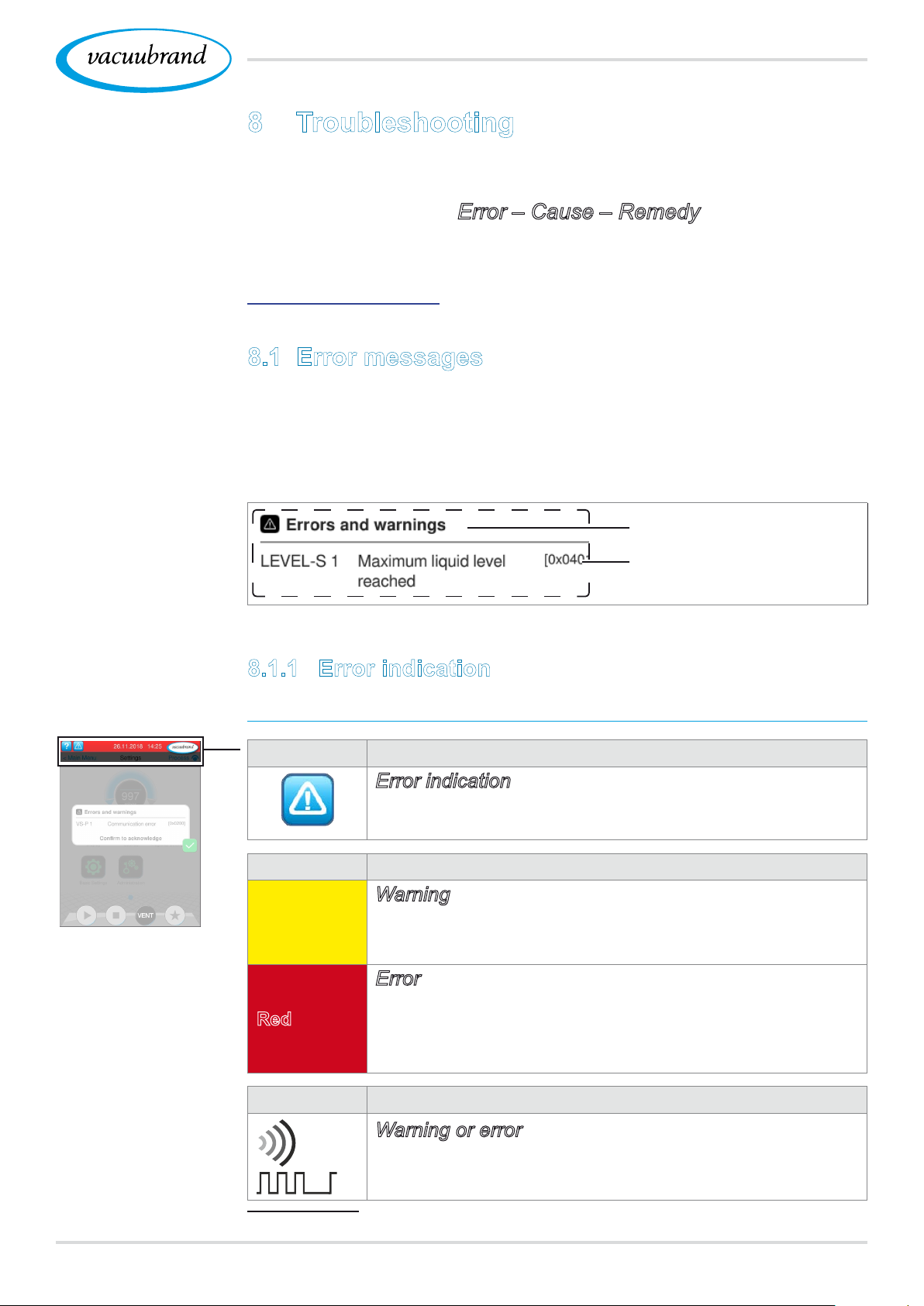
Error message
pop‑up
To identify errors and potential remedies, please refer to the
troubleshooting table Error – Cause – Remedy.
For technical assistance or errors for which you require ad‑
ditional support, please contact your local distributor or our
Service Department1.
8.1 Error messages
Errors are indicated immediately by the controller as plain text in
a pop‑up message. The status line provides a visual indication of
the extent of the error. In addition, an acoustic signal is emitted
while the error persists.
Pop‑up message
Source of error, descrip‑
tion, error code
Example
Error
8.1.1 Error indication
Error indication
Symbol Meaning
Error indication
Indication in the case of error or warning.
Tap to display text and acknowledge the error.
Color Meaning
Warning
Yellow
Red
Sound Meaning
Indicates persisting error; process continues to run.
Warnings will be reset automatically after remedy.
Error
Indicates persisting error; process stops.
Only after fault elimination and acknowledgment of
the error message the process can be restarted.
Warning or error
Shows that an error or warning is present.
Active while error status persists.
1 -> Phone: +49 9342 808-5660, fax: +49 9342 808-5555, [email protected]
7320901059_EN_VACUU·SELECT_V1.3_280119
Page 74
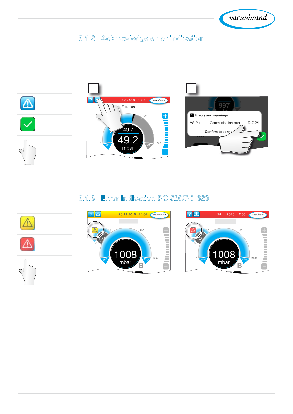
Troubleshooting
8.1.2 Acknowledge error indication
Errors must be acknowledged after the fault has been remedied.
Error information and acknowledgement
View
message
Acknowl‑
edge
Tap/press
lightly
Warning
1
2
5 Error message reset.
8.1.3 Error indication PC 520/PC 620
Error
Tap/press
lightly
Warnings and / or errors are indicated by a ashing pressure curve.
If the ashing pressure curve is pressed, the process with fault can
be called up. The process without fault continues operation. If both
processes are affected by the fault, both processes stop.
For errors the same rule applies, as for a controller with only one
pressure curve: remedy fault and acknowledge error message.
74 20901059_EN_VACUU·SELECT_V1.3_280119
Page 75
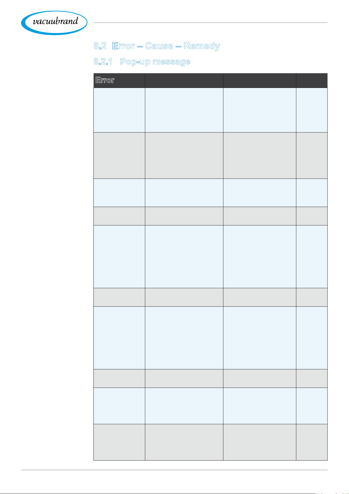
8.2 Error – Cause – Remedy
8.2.1 Pop‑up message
Troubleshooting
Error – Cause –
Remedy
Error Possible cause Remedy
Communica‑
tion error
Error at
frequency
converter (FC)
Error at control
system
Error at pump ` Check VMS‑B
Error at digital
I/O module
Error at analog
I/O module
Error at
Peltronic
Error at vacu‑
um sensor
Overpressure ` Pressure too high.
Underrange ` Pressure below mea‑
` One or more
VACUU·BUS compo‑
nents were removed.
` Deactivate relevant
VACUU·BUS com‑
ponents.
` Perform component
detection.
` Address incorrectly
congured.
` Temperature too
high.
` FC defective.
` Valve defective. ` Check address.
` Congure correct
address.
` Replace defective
component.
` Replace defective
component.
` Send in defective
(switching device).
` No power supply at
IN of I/O module.
` Plug pulled out.
` An error occurred in
the system and the
I/O module relayed it
device.
` Connect power sup‑
ply.
` Check plug‑in con‑
nection.
` Remedy cause of
external error.
to the controller.
` No power supply. ` Connect power sup‑
ply.
` Ambient temperature
too high, Peltronic
overheated.
` Performance require‑
ments too high.
` Peltronic defective.
` Eliminate cause of
overheating of the
Peltronic.
` Send in defective
component.
` Replace defective
component.
` Vacuum sensor
defective.
` Measuring range
exceeded.
` Send in defective
component.
` Acknowledge warn‑
ing indication.
` Eliminate cause of
overpressure.
` Calibrate vacuum
suring range.
` Vacuum sensor
sensor correctly.
adjustment incorrect.
Personnel
Specialist
Resp. specialist
Specialist
Resp.
specialist
Specialist,
resp.
specialist
Specialist
Specialist
Resp.
specialist
Operator,
specialist
Specialist
7520901059_EN_VACUU·SELECT_V1.3_280119
Page 76
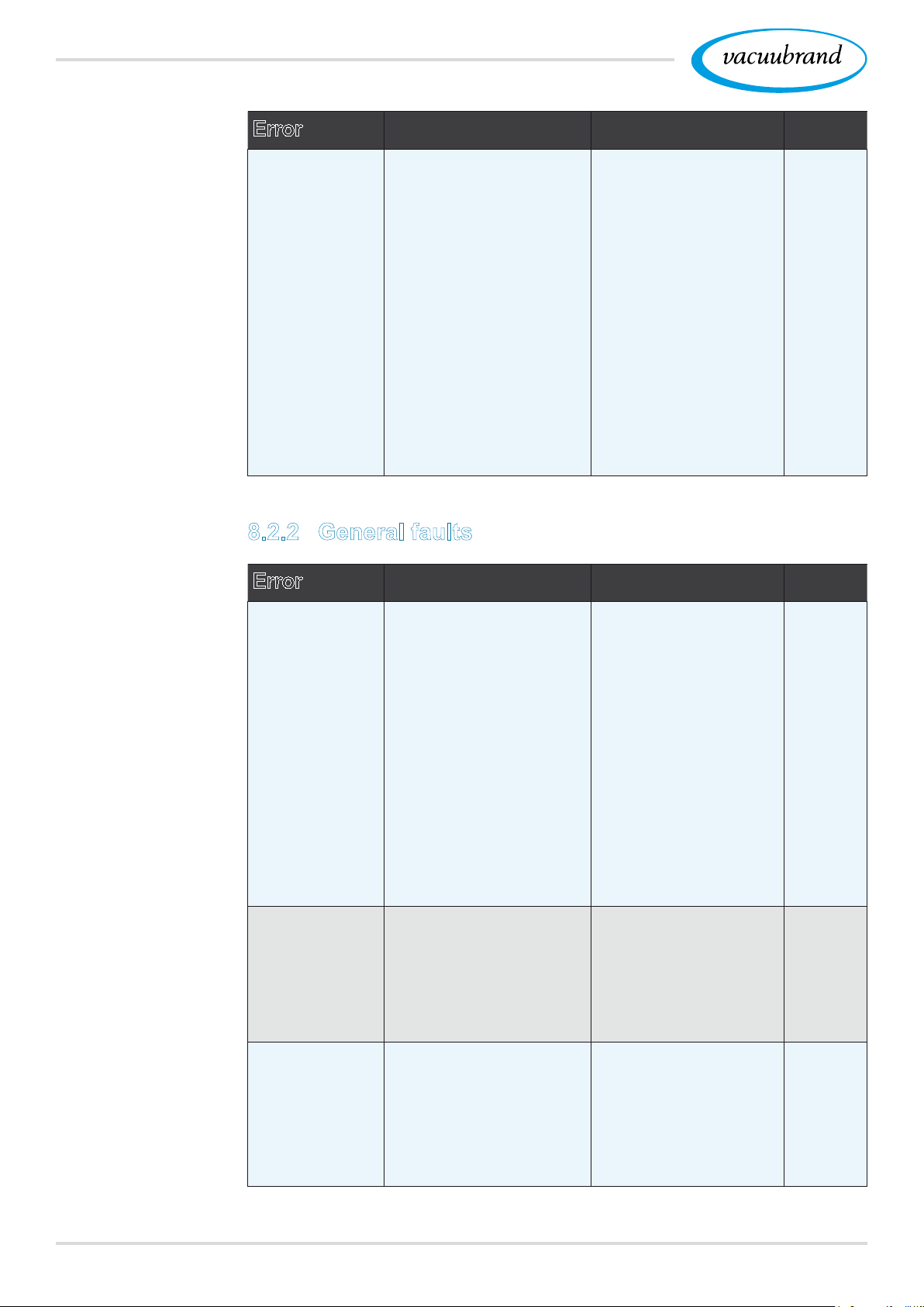
Troubleshooting
Error Possible cause Remedy
Maximum liq‑
uid level
reached
` Full status indicator
of a level sensor.
` Level sensor discon‑
nected.
` Level sensor not
adjusted correctly.
` Component defec‑ defec‑
tive.
` Empty the glass
ask or container in
question.
` Connect level sen‑
sor.
` If permanently
removed, perform
the VACUU · BUS
component detec‑
tion.
` Re‑adjust level sen‑
sor.
` Exchange defective
component.
8.2.2 General faults
Personnel
Operator
Error Possible cause Remedy
No display ` Power plug or plug‑in
power supply not cor‑
rectly plugged in or
pulled out.
` Pumping unit
switched off.
` VACUU·BUS plug‑in
connection or cables
defective or not con‑
nected.
` Controller switched
off or defective.
` Device fuse tripped.
Display frozen ` Controller in unde‑
ned state.
` Controller has frozen.
Circuit board
fuse defective
` Short circuit on the
circuit board.
` Defective accessory
connected.
` Power consumption
too high.
` Check power con‑
nection or plug‑in
power supply and
cables.
` Check VACUU·BUS
plug‑in connection
and cables to the
controller.
` Replace defective
components.
` Restart the control‑
ler.
Hold down ON/OFF
button for more
than 10 seconds
until device reboots.
` Remedy cause of
the short circuit
and replace circuit
board fuse.
` Send in.
Personnel
Operator
Operator
Resp.
specialist
76 20901059_EN_VACUU·SELECT_V1.3_280119
Page 77

Troubleshooting
Error Possible cause Remedy
Transfer failed ` No USB ash drive
connected.
` Not enough storage
space on the USB
ash drive.
Venting valve
does not oper‑
ate
` No voltage applied.
` VACUU·BUS plug‑in
connection or cables
defective or not con‑
nected.
` Venting valve dirty
(polluted).
` Venting valve in sen‑
sor defective.
` Venting valve deacti‑
vated.
` Connect a USB
ash drive with
sufcient storage
space.
` Check VACUU·BUS
plug‑in connection
and cables to the
controller.
` Clean venting valve.
` If necessary, use
another external
venting valve.
` Activate venting
valve in the control‑
ler.
Personnel
Specialist
Specialist
7720901059_EN_VACUU·SELECT_V1.3_280119
Page 78
Troubleshooting
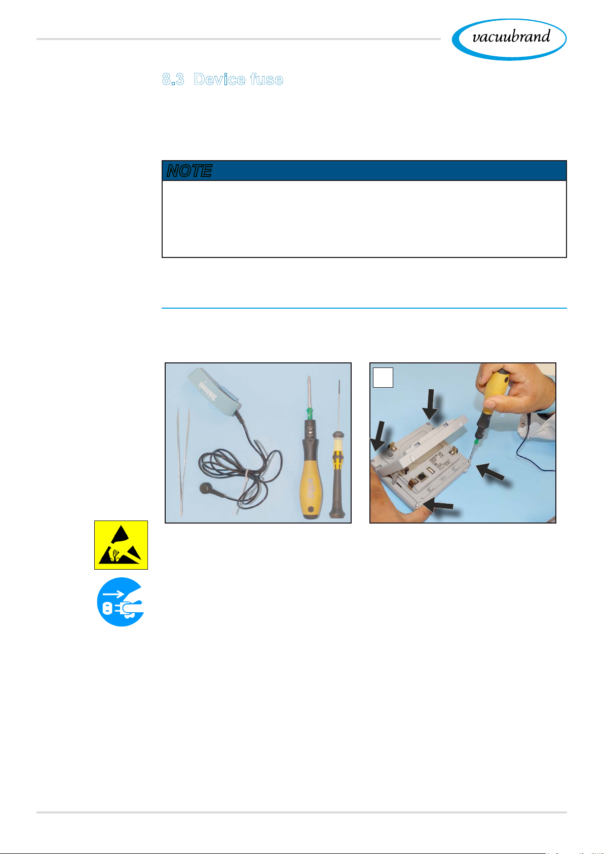
8.3 Device fuse
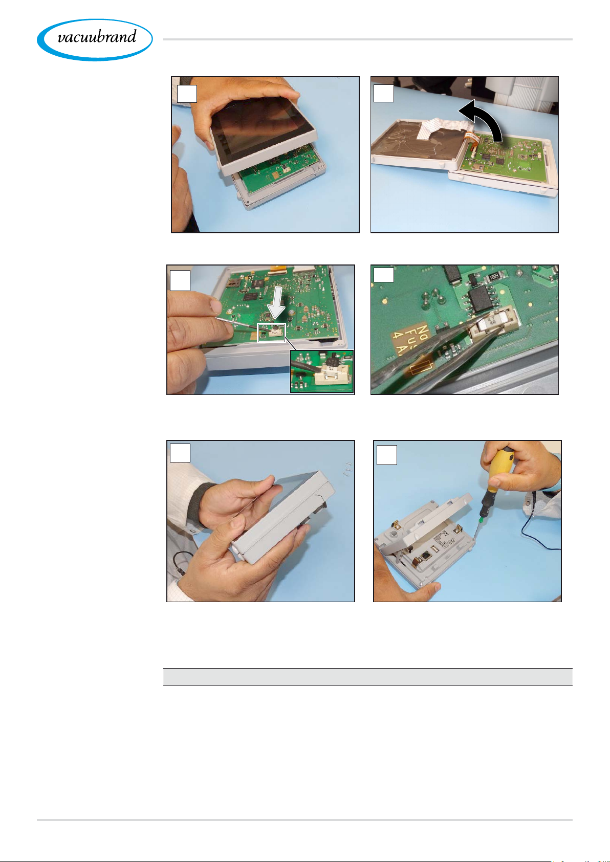
There is a device fuse, type: Nano fuse 4 A/t, on the circuit board
of the controller. If blown, the fuse can be replaced under ESD
conditions after the cause has been remedied.
NOTE
Damage possible if work is performed incorrectly.
Have maintenance work performed by a trained electrician
or at least by a person with electrotechnical expertise.
Ensure ESD safeguards when working with the circuit board.
Change device fuse
Change device fuse
ESD tools required: Grounding wristband, at‑head screwdriver
Gr. 1, Torx screwdriver with torque of TX10, tweezers.
1
Preparation:
Have the tools ready (see
image).
Disconnect the controller from
the power supply.
1. Lay the controller carefully
face down and unscrew the
4 screws in the housing.
78 20901059_EN_VACUU·SELECT_V1.3_280119
Page 79
Troubleshooting
Change device fuse
2
3
2. Carefully lift the display. 3. Carefully pivot back the display.
4
5
4. Lever the fuse out of the base. 5. Insert the new fuse into the
base.
6
7
6. Close the housing tightly. 7. Tighten the housing screws
with the Torx screwdriver;
torque 1.1 Nm.
Nano fuse 4 A/t
20612952
7920901059_EN_VACUU·SELECT_V1.3_280119
Page 80
Appendix
9 Appendix
9.1 Technical information
Type
Vacuum controller VACUU·SELECT
9.1.1 Technical data
®
Technical data
Ambient conditions
Working temperature
Storage/transport tempera‑
10‑40 °C 50–104 °F
‑10‑60 °C 14‑140 °F
(US)
ture
Max. altitude
Protection class (front) IP 20
2000 m
above sea level
6562 ft
above sea level
Relative humidity 30‑85 %, non‑condensing
Prevent condensation or contamination from dust or liquids
Electrical data
Nominal voltage
Controller output
Power supply via VACUU·BUS
24 VDC
1.2 W
®
Device fuse on circuit board Nano fuse 4 A/t
Interfaces
Plug‑in connector
VACUU·BUS
®
Ethernet (LAN)
USB port (1.0–2.0)
Patch cable min. cat. 5e RJ45
2x USB‑A 2.0, max. 0.5 A per port
Connections
VACUU·SELECT® Sensor
Venting valve, optional
Weights
Small ange KF DN 16
Hose nozzle DN 6/10
PTFE hose DN 8/10
Silicone tube DN 4/6
(US)
Controller with sensor 745 g 1.64 lb
Controller without sensor 590 g 1.3 lb
Plug‑in power supply 250 g 0.55 lb
80 20901059_EN_VACUU·SELECT_V1.3_280119
Page 81
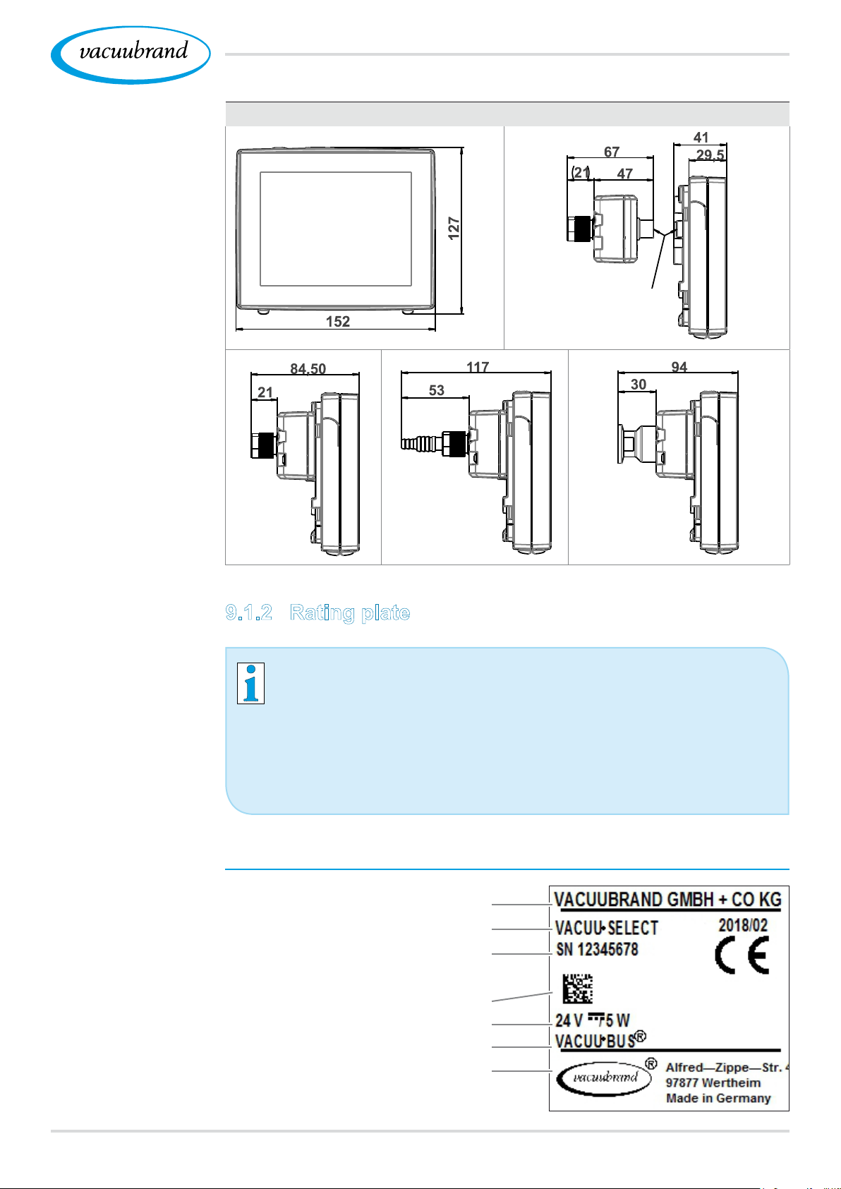
Dimensions
Appendix
Dimensions (mm)
VACUU·BUS
cable
Data on rating plate
9.1.2 Rating plate
In the event of an error, make a note of the type and serial
number on the rating plate.
When contacting our Service Department, please provide
the type and serial number from the rating plate. This will
allow us to provide you with specic support and advice for
your device.
VACUU·SELECT® rating plate, general
Manufacturer
Type
Serial number/year of
manufacture/month
Data matrix code
Power supply
VACUU·BUS compatible
address
8120901059_EN_VACUU·SELECT_V1.3_280119
Page 82
Appendix
9.1.3 VACUU·SELECT® Sensor (optional)
Wetted materials
Wetted materials
Vacuum data
Component Wetted materials
Sensor Aluminum oxide ceramic,
gold‑coated (if applicable)
Measurement chamber PPS
Small ange PP
Sealing ring at the sensor Chemically resistant
uoroelastomer
O‑ring inside small ange FKM
Hose nozzle PP
Venting valve seal FFKM
Optional: blind plugs without
venting valve
Epoxy resin
Vacuum data
Values
Measuring range
(absolute)
Accuracy of measure‑
ment
Measuring principle
1060–0.1 mbar 795–0.1 Torr
±1 mbar/hPa/Torr, ±1 digit, with
VACUU·SELECT® vacuum controller (after
adjustment, constant temperature)
Ceramic diaphragm (aluminum oxide, gold‑
coated), capacitive, gas type independent,
absolute pressure
(US)
Temperature coefcient
Maximum admissible
< ±0.15 mbar (hPa)/K < ±0.11 Torr/K
1.5 bar 1125 Torr
pressure, abs.
Maximum admissible media temperature (gas), non‑explosive atmo‑
sphere:
Short term (< 5 min)
Continuous operation
80 °C 176 °F
45 °C 113 °F
ATEX conformity II 3/‑ G IIC T4 X Internal Atm. only
Maximum admissible media temperature (gas) ` atmosphere:
Short term 40 °C 104 °F
Continuous operation
82 20901059_EN_VACUU·SELECT_V1.3_280119
40 °C 104 °F
Page 83

9.2 Ordering information
Appendix
Ordering information
Overview
of possible
VACUU·BUS®
components
(Optional)
Vacuum controller
VACUU·SELECT® with power supply unit, with sensor
VACUU·SELECT® without power sup‑
ply unit, without sensor
VACUU·SELECT® with power sup‑
ply unit, without sensor
Accessories
Vacuum hose DN 6 mm (l = 1000 mm)
PTFE hose KF 16
Silicone rubber hose 3/6 (vent with inert gas)
VACUU·BUS wall duct
DAkkS calibration with rst delivery
DAkkS recalibration
VACUU·BUS peripheral devices
Vacuum sensor VACUU·SELECT® Sensor
VACUU·SELECT® Sensor
without venting valve
VSK 3000
Order no.
20700000
20700040
20700050
Order no.
20686000
20686031
20636156
20636153
20900214
20900215
Order no.
20700020
20700021
20636657
VSP 3000
Vacuum gauge VACUU·VIEW
VACUU·VIEW extended
Vacuum valve VV‑B 6
(in‑line solenoid valve) VV‑B 6C
VV‑B 15C, KF 16
VV‑B 15C, KF 25
Cooling water valve VKW‑B
Venting valve VBM‑B
VACUU·SELECT® Sensor
Module for switching a
vacuum pump
VMS‑B
...I/O module Digital...
IN: 5‑75 VDC / OUT: 60 VDC
(2.5 A)
IN: 5‑50 VAC / OUT: 40 VAC
(2.5 A)
Analog...
IN: 0‑10 V / OUT: 0‑10 V
Analog...
IN: 4‑20 mA / OUT: 0‑10 V
Emission condenser Peltronic
Level sensor for 500 ml round bottom ask
20640530
20683220
20683210
20674290
20674291
20674210
20674215
20674220
20674217
20700020
20676030
20636228
20636229
20635425
20699905
20699908
8320901059_EN_VACUU·SELECT_V1.3_280119
Page 84
Appendix
Ordering information
Spare parts
International
sales ofces and
distribution
Spare parts
Hose nozzle DN 6/10
Small ange KF 16 PP
Order no.
20636635
20635008
Protective cap DN 10/16
O‑ring
Extension cable VACUU·BUS® 0.5 m
VACUU·BUS® 2 m
VACUU·BUS® 10 m
VACUU·BUS
®
Y adapter
Safety information for vacuum equipment
Instructions for use
20612875
20612552
22618493
20636656
20999254
20901057
Sources of supply
Purchase original accessories and original spare parts from a
subsidiary of VACUUBRAND GMBH + CO KG or your local dis‑
tributor.
Information about our complete product range is available
in the current product catalog.
Your local distributor or VACUUBRAND GMBH + CO KG
sales oce is available to assist you with orders, questions
on vacuum control and optimal accessories.
9.3 License and privacy information
This product contains open source software. For license informa‑
tion, please go to the VACUU·SELECT service menu
Device information and refer to the legal notices section.
To improve device diagnostics in the event of an error or during
service, diagnostics data are stored on the device. All diagnostics
data can be downloaded to an USB ash drive from the service
menu. Diagnostics data storage can be deactivated from the same
menu.
84 20901059_EN_VACUU·SELECT_V1.3_280119
Page 85
9.4 Service
Appendix
Service offer and
service range
Take advantage of the comprehensive range of servic‑
es available from VACUUBRAND GMBH + CO KG.
Services in detail
Product consultation and practical solutions
Fast delivery of spare parts and accessories
Professional maintenance
Immediate repairs processing
On‑site service (on request)
Calibration (DAkkS‑accredited)
With Health and Safety Clearance form: return, disposal.
Visit our website for further information: www.vacuubrand.com.
Service handling
Follow the terms of
service
Return (reshipment)
1. Contact your local distributor or our Service Department.
2. Request an RMA no. for your order.
3. Clean the product thoroughly or if necessary, decontaminate
it professionally.
4. Download the Health and Safety Clearance form.
5. Fill out the Health and Safety Clearance form in full.
6. Return your product, including:
RMA no. and description of the error
Repair or service order
Health and Safety Clearance form
Attach everything to the outside of the package
Reduce downtime, speed up processing. Please have the
required data and documents at hand when contacting our
Service Department.
Your order can be quickly and easily processed.
Hazards can be prevented.
A brief description and/or photos will help locate the
source of the error.
8520901059_EN_VACUU·SELECT_V1.3_280119
Page 86

Appendix
9.5 Index
Index
A
Abbreviations .................................... 12
Action steps ...................................... 11
Add favorites..................................... 56
Additional symbols............................ 10
Adjust motor speed..................... 51, 52
Adjust parameter .............................. 52
Adjust pressure setpoint ................... 44
Administration ................................... 66
ATEX equipment category ................ 19
ATEX equipment labeling ................. 19
B
Basic settings ............................. 64, 65
C
Certicate (online) ............................ 88
Change device fuse .................... 78, 79
Change language ............................. 64
Color coding of status bar................. 42
Connection options ........................... 34
Connect venting valve ...................... 37
Context menu for applications .......... 55
Context menus VACUU·BUS .......... 69
Continuous venting ........................... 50
Copyright © ........................................ 7
Country‑specic plug attachment ..... 32
Create application............................. 61
D
Data logger ....................................... 71
Description of vacuum controller ...... 21
Description of VACUU·SELECT® Sen‑
sor..................................................... 25
Display and operating elements ....... 41
Display conventions............................ 9
Display elements .............................. 42
Display of operating steps ................ 11
Disposal ............................................ 20
Distributors ....................................... 84
E
EC Declaration of Conformity ........... 88
Edit application ................................. 62
Electrical connection......................... 32
Error – Cause – Remedy .................. 75
Error message pop‑up ...................... 73
Explanation of safety symbols .......... 10
F
Foreseeable misuse ......................... 15
Front view ......................................... 22
I
Icons ................................................. 10
Import/export .................................... 68
Improper use .............................. 14, 15
Instruction modules ............................ 8
L
Landscape ........................................ 40
Landscape view ................................ 40
Limitation of use ............................... 28
M
Main screen ...................................... 41
Mandatory sign ................................. 10
Manual structure ................................. 8
Measurement chamber..................... 82
O
ON/OFF button ................................. 38
Operating elements and symbols ..... 44
Operating elements for control ......... 46
Operating elements – process steps 45
Operating panel .......................... 13, 22
Operating steps ................................ 11
Operating steps as graphics ............. 11
Ordering information ......................... 83
P
Parameter list ................................... 51
Personnel qualication ..................... 16
Plug‑in power supply ........................ 32
Pop‑up window ................................. 43
Portrait .............................................. 40
Portrait view ...................................... 40
Power supply .................................... 33
Power supply to controller ................ 33
Power supply via peripheral device .. 33
Power supply via plug‑in power supply .
32
Pressure display PC 520, PC 620 .... 42
Prevent explosive mixtures............... 19
Process screen ................................. 41
Process step ..................................... 59
Process step conguration ............... 59
Process step section ........................ 59
Product description ........................... 21
Product‑specic terms ...................... 13
Prohibition sign ................................. 10
Protective clothing ............................ 17
Q
Quality standard ............................... 17
G
Gestures ........................................... 39
Goods receipt ................................... 28
H
Handling instructions ........................ 11
Health and Safety Clearance form ... 85
86 20901059_EN_VACUU·SELECT_V1.3_280119
R
Rating plate ................................ 25, 81
reboot ............................................... 38
Remove favorites.............................. 56
Responsibility matrix......................... 16
Return (reshipment).......................... 85
Page 87

S
Safety ................................................. 7
Safety information............................. 14
Screen orientations........................... 40
Select application ............................. 47
Service.............................................. 72
Service handling ............................... 85
service range .................................... 85
Side view .......................................... 24
Sounds ............................................. 42
Sources of supply ............................. 84
Standard pressure display ................ 42
Start application ................................ 47
Status bar ......................................... 44
Stop application ................................ 51
Switch off diagnostics data storage
(privacy notice) ................................. 84
Switch on device............................... 38
Symbols ............................................ 10
Symbols with operating function ....... 44
Appendix
T
Technical data................................... 80
Technical support.............................. 73
Term denition .................................. 13
Tool tips ............................................ 58
Top view............................................ 22
Top view, side view ........................... 25
Touchscreen operation ..................... 39
U
User information ................................. 7
V
VACUU·BUS® .................................. 13
VACUU·BUS accessories ................. 83
VACUU·BUS® connector ................. 13
VACUU·BUS simplied ..................... 69
Vacuum connection .......................... 34
Vacuum data ..................................... 82
VACUU·SELECT® Sensor ............... 25
VACUU·VIEW ................................... 83
VACUU·VIEW extended ................... 83
Vent briey ........................................ 50
Venting connection (option) .............. 37
Vent with ambient air ........................ 37
Vent with inert gas ............................ 37
View application editor ...................... 57
View applications submenu .............. 55
View main menu ............................... 54
View pressure graph ......................... 53
W
Warning symbol ................................ 10
Wetted materials ............................... 82
8720901059_EN_VACUU·SELECT_V1.3_280119
Page 88
Appendix
9.6 EU Declaration of conformity
EU‑Konformitätserklärung
EC Declaration of Conformity
Déclaration CE de conformité
Hersteller / Manufacturer / Fabricant:
VACUUBRAND GMBH + CO KG · Alfred‑Zippe‑Str. 4 · 97877 Wertheim · Germany
Hiermit erklärt der Hersteller, dass das Gerät konform ist mit den Bestimmungen
der Richtlinien:
Hereby the manufacturer declares that the device is in conformity with the
directives:
Par la présente, le fabricant déclare, que le dispositif est conforme aux directives:
2014/30/EU (EMV‑RL), 2014/35/EU (N‑RL), 2011/65/EU (RoHS‑2)
Vakuum‑Controller / Vacuum controller / Régulateur de vide
Typ / Type / Type: VACUU·SELECT
Artikelnummer / Order number / Numéro d‘article: 2070000, 20700040, 20700050
20700061, 20700100, 20700101, 20700110, 20700111, 20635118
Seriennummer / Serial number / Numéro de série: Siehe Typenschild / See rating
plate / Voir plaque signalétique
Angewandte harmonisierte Normen / Harmonized standards applied /
Normes harmonisées utilisées: DIN EN 12100:2011, DIN EN 61326‑1:2013,
DIN EN 61010‑1:2010 (Ed. 3), DIN EN 61010‑1:2011, DIN EN 50581:2013
Bevollmächtigter für die Zusammenstellung der technischen Unterlagen / Person
authorised to compile the technical le / Personne autorisée à constituer le dossier
technique: Dr. J. Dirscherl · VACUUBRAND GMBH + CO KG · Germany
Ort, Datum / place, date / lieu, date: Wertheim, 28.01.2019
®
i. A.
(Dr. F. Gitmans) (Dr. A. Wollschläger)
Geschäftsführer /
Managing Director / Gérant
VACUUBRAND GMBH + CO KG
Alfred‑Zippe‑Str. 4
97877 Wertheim
www.vacuubrand.com/certicate
88 20901059_EN_VACUU·SELECT_V1.3_280119
Regulatory Affairs Manager /
Directrice des affaires réglementaires
Phone: +49 9342 808‑0
Fax: +49 9342 808‑5555
E‑Mail: [email protected]
Web: www.vacuubrand.com
Page 89

8920901059_EN_VACUU·SELECT_V1.3_280119
Page 90

90 20901059_EN_VACUU·SELECT_V1.3_280119
Page 91

9120901059_EN_VACUU·SELECT_V1.3_280119
Page 92

Technology for Vacuum Systems
Manufacturer:
VACUUBRAND GMBH + CO KG
Alfred‑Zippe‑Str. 4
97877 Wertheim
GERMANY
Phone:
Head ofce +49 9342 808‑0
Sales +49 9342 808‑5550
Service +49 9342 808‑5660
Fax: +49 9342 808‑5555
Version: 20901059_EN_VACUU·SELECT_V1.3_280119 – TDD2 – © VACUUBRAND GMBH + CO KG – 2018
 Loading...