

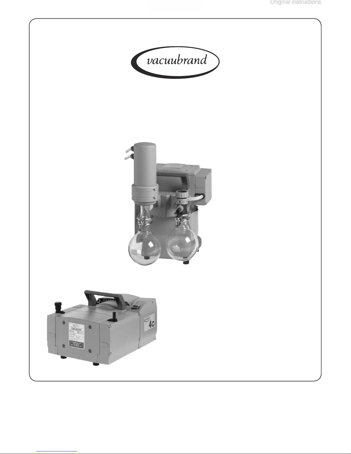
vacuubrand MZ 2C NT + AK + EK, MZ 2C NT, MZ 2C NT + AK Synchro + EK, ME 4C NT, MD 4C NT + 2 AK Instructions For Use Manual
...Page 1
page 1 of 75
MZ 2C NT + 2 AK
Page 2
After sales service:
Your VACUUBRAND diaphragm pumps are designed to provide you with
VACUUBRAND diaphragm pumps combine our many years of experi
velopments in material and manufacturing technology.
After completion of the endurance run, every pump is tested, and must
We are committed to providing our customers only pumps that meet this
While our pumps cannot eliminate all of your work, we design, manufac
Yours,
VACUUBRAND GMBH + CO KG
®®®®®
VACUUBRAND
®
(US-Reg.No
Page 3

Ambient conditions
Gas inlet temperatures
Wetted parts
Abbreviations
Pump parts
42
44
45
47
Accessories
Cleaning and inspecting the pump heads
Replacing the diaphragm
Replacing the valves
Replacing the overpressure safety relief device
Replacing the fuse
Warranty
Page 4

page 9 of 75
Safety information!
tion.
from the pump and the pumped substances.
VACUUBRAND disclaims any liability for inappropri
to follow instructions contained in this manual.
NOTICE
Page 5
will
result in death or serious injury.
WARNING indicates a hazardous situation which, if
result in death or serious injury.
/
NOTICE
Page 6
page 11 of 75
the equipment, as well as the electromagnetic compat
NOTICE
Page 7
tures if installing the pump in a cabinet or a housing.
tomatic ventilation system if necessary. If pumping hot
ture (see ”Technical data”, pg. 24).
only as intended
trical supply
and a suitable ground point. As such,
the plug must be plugged into an outlet that is properly
NOTICE
Page 8
page 13 of 75
faces.
that the system which you are going to evacuate is
at in
between inlet and outlet. See section
with overpressure at the inlet.
valve.
to be sure that the power source and the equipment
voltage selection switch is set correctly. Do not change
the setting of the voltage selection switch while the
Page 9

fore setting the voltage selection switch.
is always free and
that it cannot get blocked. If installing an optional cool
ventilation.
Allow the equipment to equilibrate to ambient temperature
(regulations and guidelines).
Ambient conditions
NOTICE
Page 10
page 15 of 75
formity”) with regard to design, type and model. Directive
tentially explosive atmospheres.
without the
are
for the
with those pumps.
according to ATEX, but they are
Important information:
to pump any of the sub
NOTICE
Page 11
without air,
for operation below
the pump
substances which may form
inside the pump. The pumps are not suitable for
the pump. Deposits and condensate in the pump may
inside the pump, e.g., in
the pump chambers (the pump chamber is the part
the pumped media.
When changing the substances pumped, we recom
Page 12
page 17 of 75
Adopt suitable measures to prevent the release of dan
You must take suitable precautions to prevent any for
failure, mechanically generated sparks, hot surfaces
tially explosive mixtures at the outlet of the pump, or
vider.
tect people from the effects of dangerous substances
Page 13
failure of connected components or of parts of the sup
failure or in case of a leak in the manifold, pumped
leak rate of the equipment
might render
Adopt suitable measures to prevent contamination of
the pumped substances or the environment.
that its inlet pipeline is not contaminated.
the equipment. Hot parts may cause burns if touched.
Adopt suitable measures to prevent any danger aris
at the waste vapor
NOTICE
Page 14
page 19 of 75
see ”Accessories”, pg
in the winding.
focus on the maintenance and repair of vacuum pumps.
NOTICE
Page 15
tally. Never operate the pump if covers or other
before starting
Wear parts have to be replaced regularly.
the vicinity
Vent the pump before starting maintenance. Isolate
the pump and other components from the vacuum sys
Page 16

page 21 of 75
is done only by suitably trained
NOTICE
Page 17
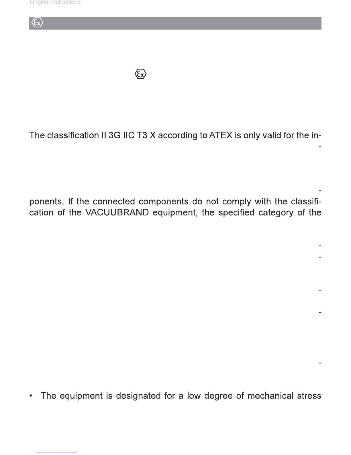
VACUUBRAND equipment bearing mark (see rating plate)
II 3G IIC T3 X
VACUUBRAND equipment is no longer valid.
Vacuum pumps and vacuum gauges in category 3 are intended for con
Important information: Equipment marking (ATEX)
Page 18
page 23 of 75
After any intervention at the equipment (e.g., repair / maintenance) the ul
After any intervention at the vacuum sensor, the leak rate of the equip
Attention: This manual is not available in all
Page 19
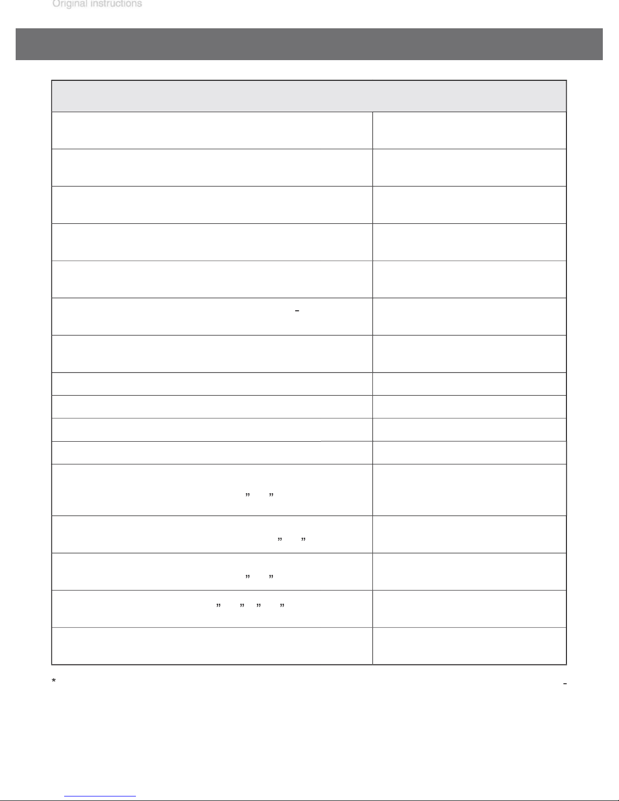
Technical data
ture during operation (no condensation)
A-weighted emission sound pressure
45
psi
(bar)
psi
(bar)
psi
(bar)
Maximum permissible pressure (absolute) at gas ballast valve
No-load speed 50/60 Hz rpm 1500 / 1800
Device fuse
psi
(bar)
°F
(°C)
% 30 to 85
ft
(m)
14 to 140 / 50 to 104
(-10 to +60 / +10 to +40)
16
(1.1)
16
(1.1)
16
(1.1)
17.5
(1.2)
6500
(2000)
Motor protection thermal cutout, manual reset
Degree of protection IEC 529
Coolant connection
(waste vapor condenser, only
Maximum permissible pressure of
coolant at waste vapor condenser (
Permissible range of coolant temperature
(waste vapor condenser, only
Volume of catchpot (only
AK
EK
EK
/
EK
)
)
EK
)
)
psi
(bar)
°F
(°C)
quarts
(ml)
dB(A)
hose nozzle for tubing
I.D. 1/4” - 5/16”
(hose nozzle DN 6-8 mm)
87 (absolute)
(6 (absolute))
5 to 68
(-15 to +20)
Page 20
page 25 of 75
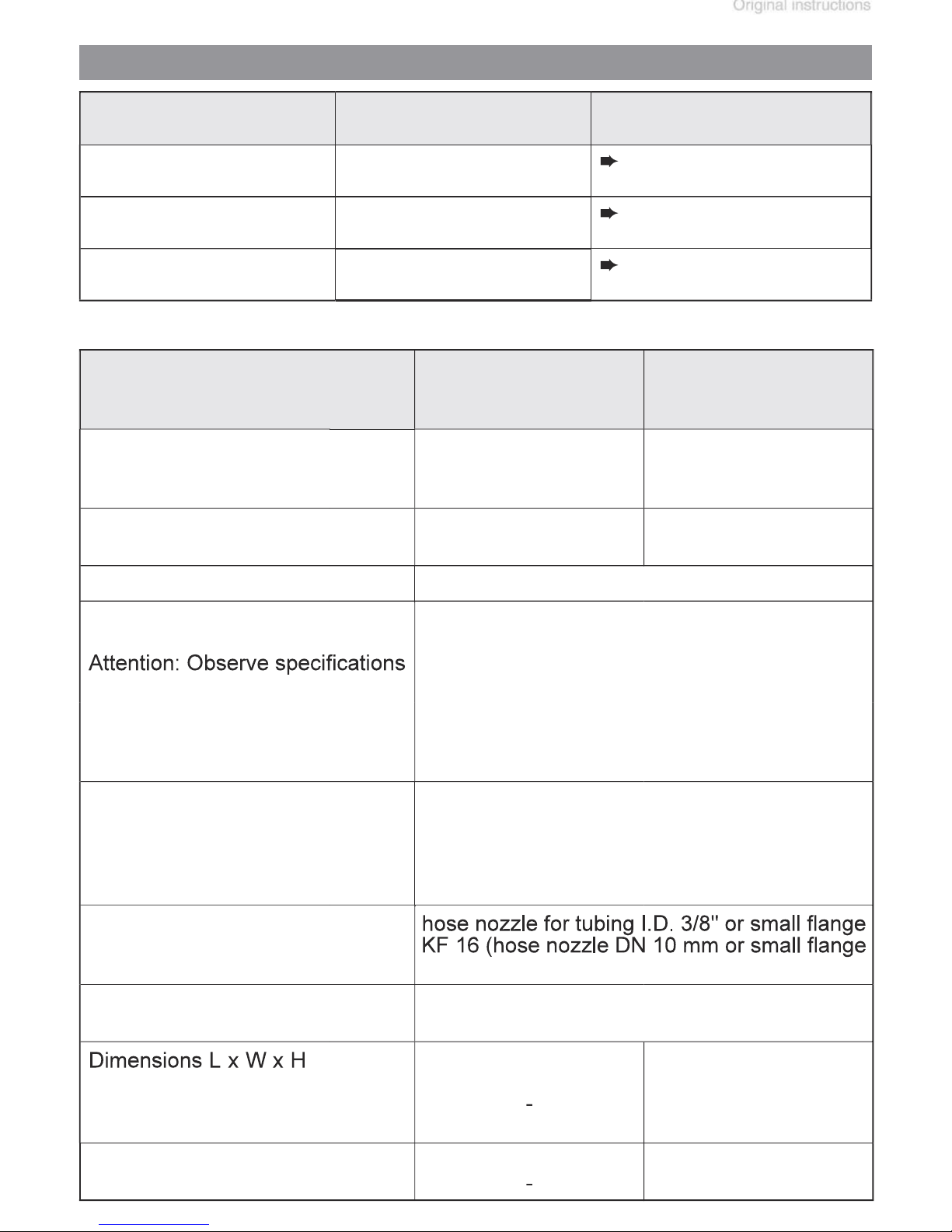
Gas inlet temperatures
temperatures at inlet
50 °F to 104 °F
(+10°C to +40°C)
32 °F to 140 °F*
(0°C to +60°C*)
14 °F to 176 °F*
(-10°C to +80°C*)
Type ME 2C NT
ME 4C NT + 2 AK
Maximum pumping
speed* 50/60 Hz
(ISO 21360)
Ultimate vacuum
(absolute)
Rated motor power hp (kW) 0.24 (0.18)
Dual voltage motor
Maximum rated current at:
100-115 V~ 50/60 Hz, A
120 V~ 60 Hz
200-230 V~ 50/60 Hz A
230 V~ 50/60 Hz A
cfm
(m3/h)
Torr
(mbar)
1.2 / 1.4
(2.1 / 2.4)
52.5
(70)
100-115 V~ 50/60 Hz, 120V~ 60 Hz
230 V~ 50/60 Hz
ME 4C NT
2.3 / 2.6
(3.9 / 4.3)
52.5
(70)
Inlet
Outlet
approx.
design 2 AK
Weight approx.
design 2 AK
KF 16)
hose nozzle for tubing I.D. 3/8”
(hose nozzle DN 10 mm)
in
(mm)
in
(mm)
lbs. (kg)
lbs. (kg)
Page 21
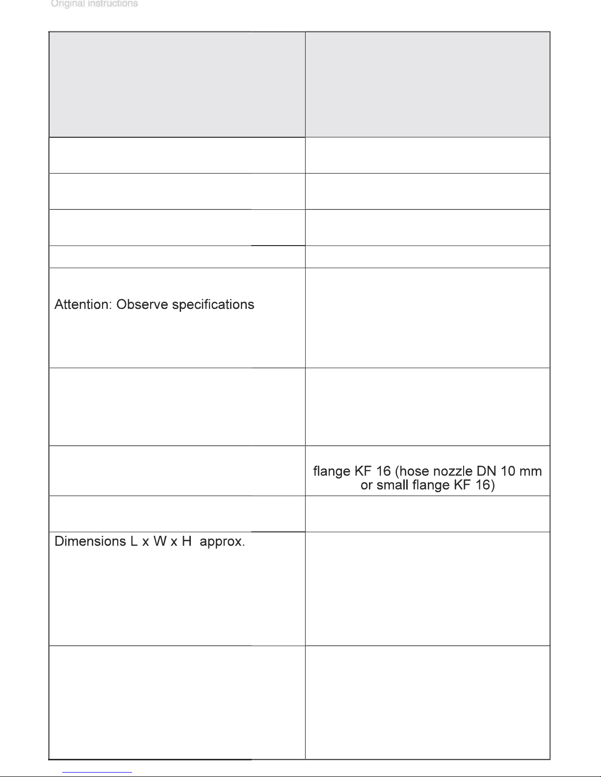
Type
MZ 2C NT
MZ 2C NT + 2 AK
MZ 2C NT + AK + EK
MZ 2C NT + AK SYNCHRO + EK
MZ 2C NT + AK + M + D
PC 101 NT
Maximum pumping speed*
50/60 Hz (ISO 21360)
Ultimate vacuum (absolute)
without gas ballast
Ultimate vacuum (absolute)
with gas ballast
Rated motor power hp (kW) 0.24 (0.18)
Dual voltage motor
Maximum rated current at:
100-115 V~ 50/60 Hz,
120 V~ 60 Hz
200-230 V~ 50/60 Hz
230 V~ 50/60 Hz
cfm
(m3/h)
Torr
(mbar)
Torr
(mbar)
A
A
A
1.2 / 1.4
(2.0 / 2.3)
5.3
(7)
9
(12)
100-115 V~ 50/60 Hz, 120V~ 60 Hz
230 V~ 50/60 Hz
Inlet
Outlet
Pump:
Vacuum systems:
design 2 AK
design AK + EK design
AK SYNCHRO + EK
design AK + M + D
PC 101 NT
Weight approx.
Pump:
Vacuum systems:
design 2 AK
design AK + EK
design AK SYNCHRO + EK
design AK + M + D
PC 101 NT
hose nozzle for tubing I.D. 3/8" or small
hose nozzle for tubing I.D. 3/8”
(hose nozzle DN 10 mm)
in (mm)
in (mm)
in (mm)
in (mm)
in (mm)
in (mm)
lbs. (kg)
lbs. (kg)
lbs. (kg)
lbs. (kg)
lbs. (kg)
lbs. (kg)
Page 22
page 27 of 75
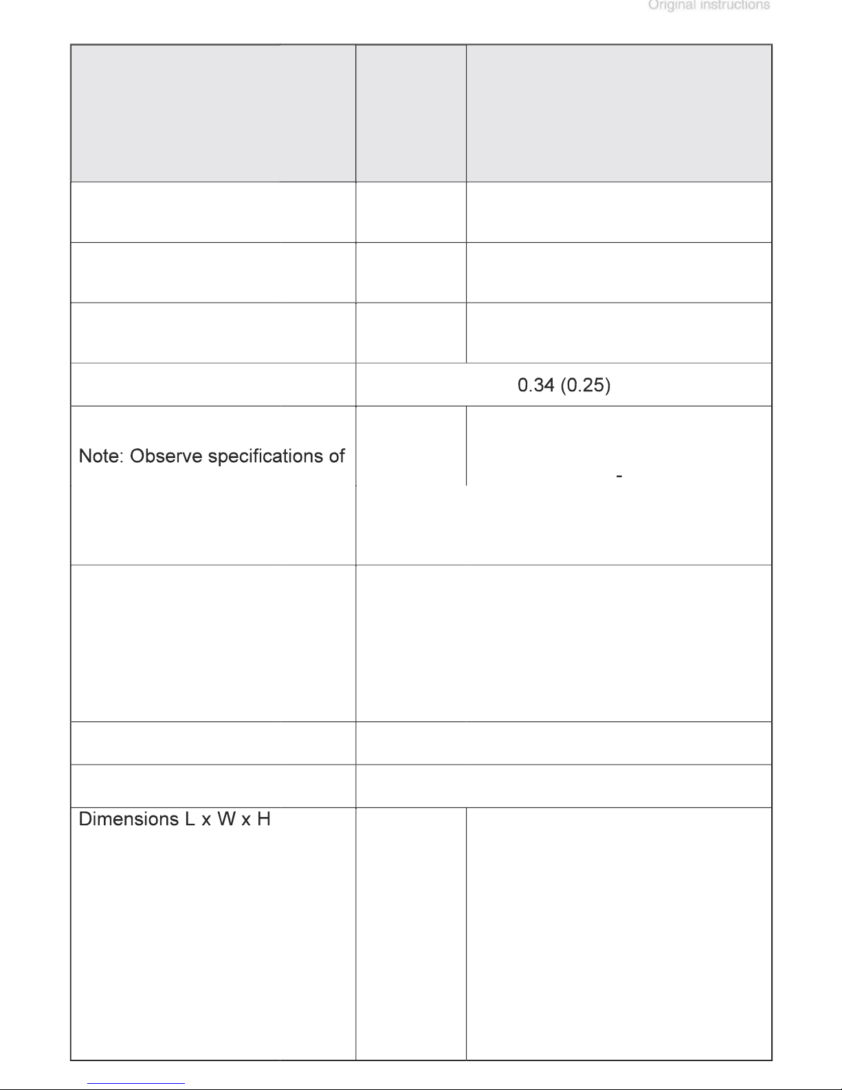
Type
200-230 V~ 50/60 Hz
4.0
ME 8C NT
ME 8C NT
+ 2 AK
MD 4C NT
MD 4C NT + 2 AK
MD 4C NT + AK + EK
MD 4C NT +
AK SYNCHRO + EK
PC 201 NT
Maximum pumping
speed* 50/60 Hz
(ISO 21360)
Ultimate vacuum
(absolute)
without gas ballast
Ultimate vacuum
(absolute)
with gas ballast
Rated motor power hp (kW)
Dual voltage motor
Maximum rated cur-
rent at:
100 V~ 50/60 Hz
120 V~ 60 Hz
100-115 V~ 50/60 Hz,
120V~ 60 Hz
200-230 V~ 50/60 Hz
230V~ 50/60 Hz
Inlet
cfm
(m3/h)
Torr
(mbar)
Torr
(mbar)
A
A
A
A
A
4.0 / 4.6
(7.1 / 7.8)
52.5
(70)
-
100 V~
50/60 Hz
120 V~ 60 Hz
hose nozzle for tubing I.D. 3/8"
2.0 / 2.2
(3.4 / 3.8)
1.1
(1.5)
2.3
(3)
(hose nozzle DN 10 mm)
Outlet
approx.
Pump:
Vacuum systems:
design 2 AK
design AK + EK
design
AK SYNCHRO + EK
PC 201 NT
in (mm)
in (mm)
in (mm)
in (mm)
in (mm)
hose nozzle for tubing I.D. 3/8"
12.8 x 9.6 x
7.8
(325 x 243
x 198)
12.6 x 9.6 x
14.7 (319 x
243 x 374)
-
-
-
(hose nozzle DN 10 mm)
12.8 x 9.6 x 7.8 (325 x 243 x 198)
12.6 x 9.6 x 14.7 (319 x 243 x 374)
12.8 x 9.6 x 15.8 (326 x 243 x 402)
12.8 x 9.8 x 15.8 (326 x 248 x 402)
12.8 x 9.6 x 15.8 (326 x 243 x 402)
Page 23
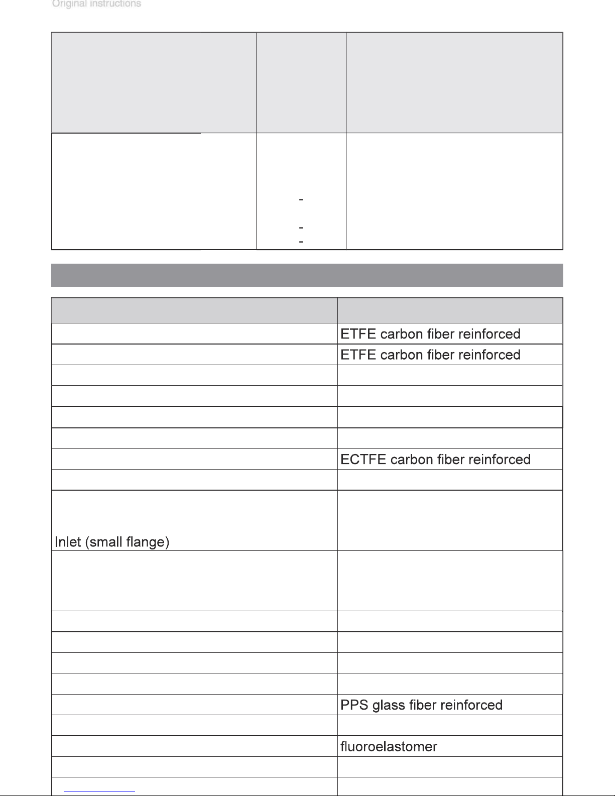
Exhaust waste vapor condenser / catchpot
Borosilicate glass
MD 4C NT
ME 8C NT
MD 4C NT + 2 AK
MD 4C NT + AK + EK
Type
ME 8C NT
+ 2 AK
MD 4C NT +
AK SYNCHRO + EK
PC 201 NT
Weight approx.
Pump:
Vacuum systems:
design 2 AK
design AK + EK
design
AK SYNCHRO + EK
PC 201 NT
lbs. (kg)
lbs. (kg)
lbs. (kg)
lbs. (kg)
lbs. (kg)
Wetted parts
Components Wetted materials
Head cover
Diaphragm clamping disc
Diaphragm PTFE
Valves (ME 2C NT/ME 4C NT/ME 8C NT) PTFE
Valves (MZ 2C NT/MD 4C NT/ME 8C NT +2AK) FFKM
O-rings FPM
Valve head
Gas ballast tube PTFE carbon reinforced
Inlet (hose nozzle)
Pump
Vacuum systems
Outlet (hose nozzle)
Pump / MZ 2C NT + AK + M + D
Vacuum systems (waste vapor condenser)
Vacuum systems (2 AK)
Tubing PTFE
Flow control diaphragm PTFE
PTFE carbon reinforced
PP (PBT only SYNCHRO designs)
stainless steel
PTFE carbon reinforced
PET
PP
Valve block (SYNCHRO design) PP
Valves (valve block SYNCHRO) FFKM
Distribution head
Blind plug PP
O-ring at catchpot
Overpressure safety relief device PTFE / silicone rubber
Page 24
page 29 of 75
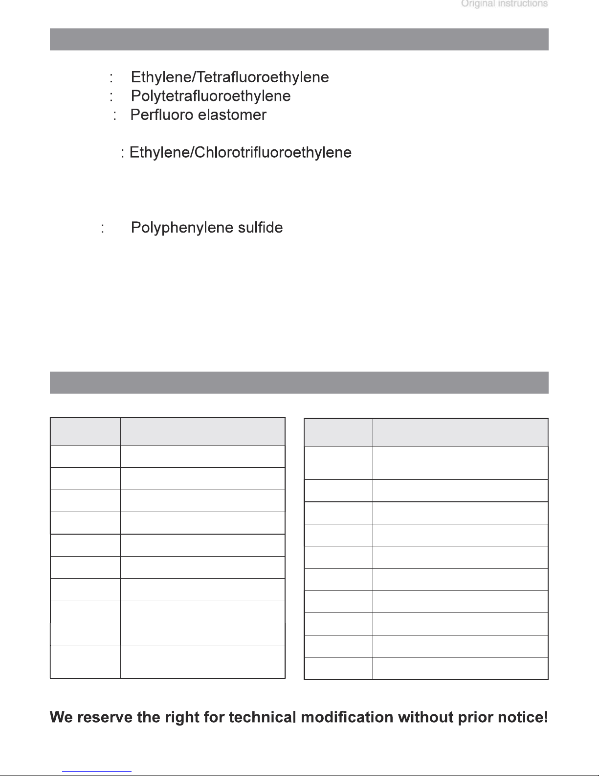
Abbreviations
AK
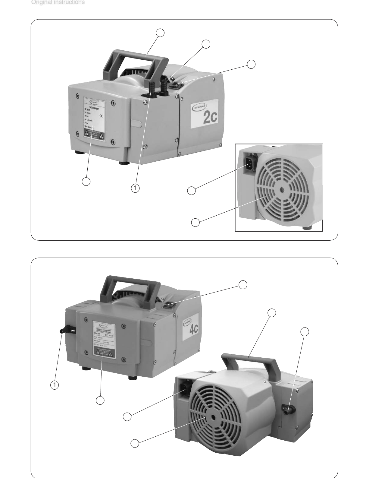
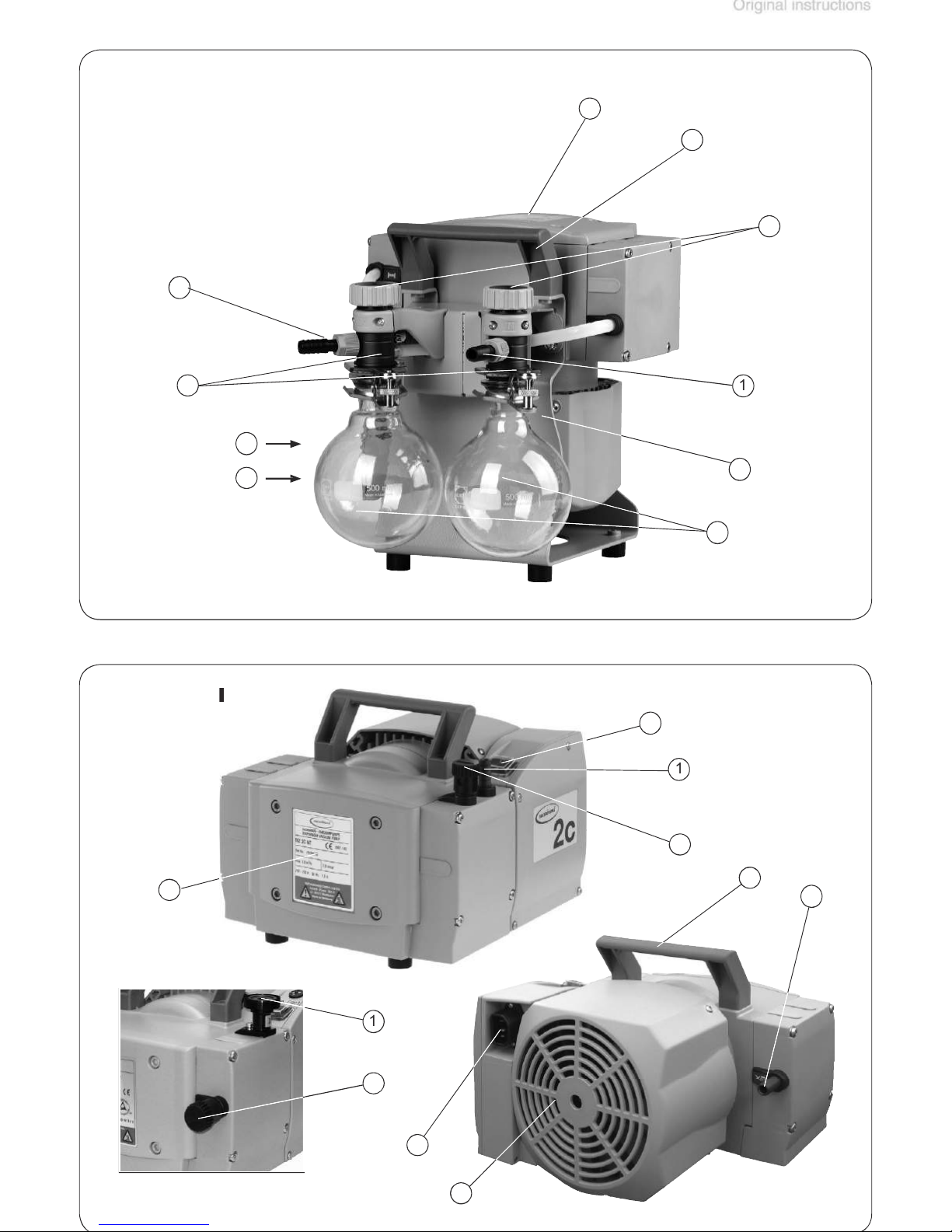
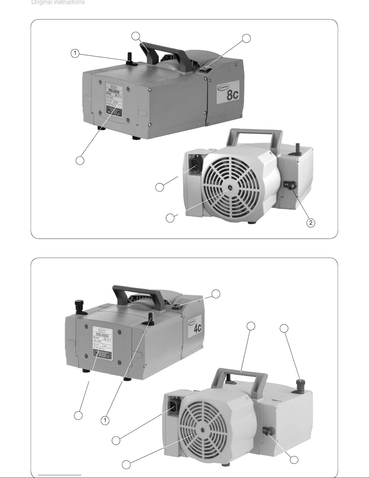
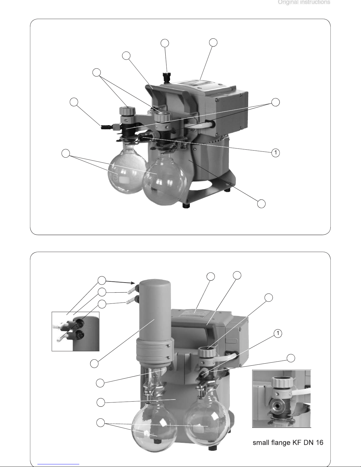
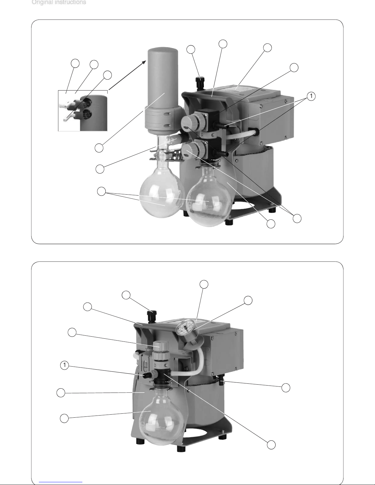
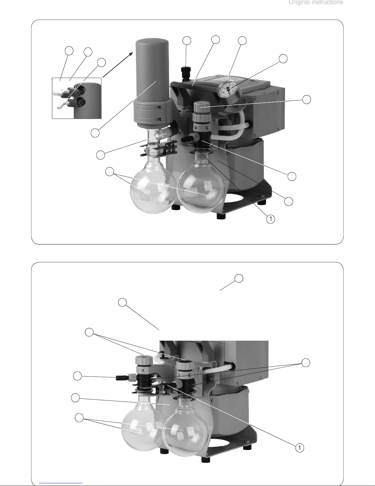
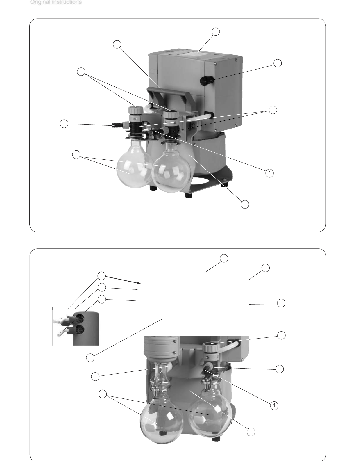
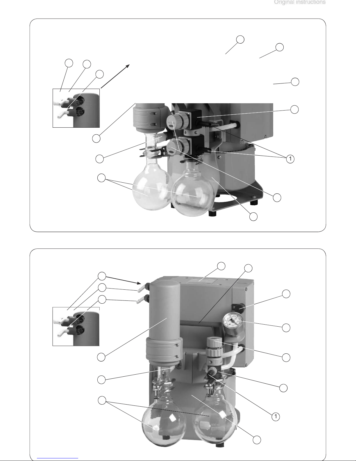
Pump parts
Position Component
1 Inlet
2 Outlet
3
4
5
6 Handle
7
8 Fan
9 Catchpot
10
Position Component
11
12
13
14 Flow control diaphragm
15 Manometer
16 Valve block
17 Distribution head
18 Blind plug
19 Voltage selection switch
20 Pump support
Page 25
4
4
Page 26
page 31 of 75
4
4
Page 27
4
4
Page 28
page 33 of 75
Page 29
Page 30
page 35 of 75
Page 31
Page 32
page 37 of 75
Page 33
the outlet, install an appropriate system to catch and
to ensure an unimpeded discharge of gas. The cross-
the pump’s exhaust connection.
Use and operation
Page 34
page 39 of 75
Always install outlet tubing descending from the pump or
NOTICE
Voltage selection switch:
voltage selection
at the terminal box of the pump to the supply
voltage:
voltage selection
to be sure that the power source and the equipment
Page 35
When assembling, ensure
vacuum-tightness
with hose clamps, to protect against accidental detach
To reduce pump noise emanating from the pump exhaust
Assembling the hose nozzle with union nut:
valves.
tions with condensable vapors.
Assemble the catchpots at the inlet and at
the outlet using joint clips.
Assemble the hose nozzles for coolant inlet
en
port, connect an exhaust hose or use a silencer (see ”Accessories”, pg. 48).
Page 36
page 41 of 75
Attach the tubing of the coolant circuit to the respective
to the surrounding atmosphere. If appropriate, connect
the exhaust line to a suitable treatment system.
valves from damage.
is always unob
waste vapor condenser: 87 psi (6
NOTICE
hose nozzles for tubing I.D. 1/4”-5/16”
I.D. 3/8” (
Page 37
Vent and dispose of
vapors
at the outlet of the pump appropriately.
tubing or exhaust valve) at the outlet. Ensure that the
ft (2000 m) above mean sea level, check compatibility
with applicable safety requirements, and adopt suit
at outlet and the
ference
between inlet and outlet ports.
Attempts to start the pump at higher pressure difference
NOTICE
Page 38
page 43 of 75
to help purge any
for a long time may cause clogging of the silencer. Check
in the winding.
A warm up period (approximately 15 min.) is required to
NOTICE
Page 39
valve slightly hand-tight. Further tightening will not in
Air and pumped media might react inside the pump or
valve can never lead to hazardous, explosive or other
wise dangerous mixtures. If in doubt, use inert gas.
vapors. Turn gas ballast cap to open valve.
the gas ballast cap is pointing towards the
With gas ballast valve open, the ultimate
vacuum will be reduced.
NOTICE
NOTICE
Page 40
page 45 of 75
to connect an inert gas supply line (see ”Accessories”,
vapor condenser.
to the surrounding atmosphere.
I.D. 3/8” (
is always free
waste vapor condenser: 87 psi (6
Page 41
valve (see ”Accessories”, pg. 48)
waste vapor condenser: 5 °F to 68 °F (-15°C to +20°C)
Admit air or inert gas (via the pump inlet) to restore at
NOTICE
NOTICE
Page 42

page 47 of 75
Allow the pump to continue to run at atmospheric pres
NOTICE
Page 43
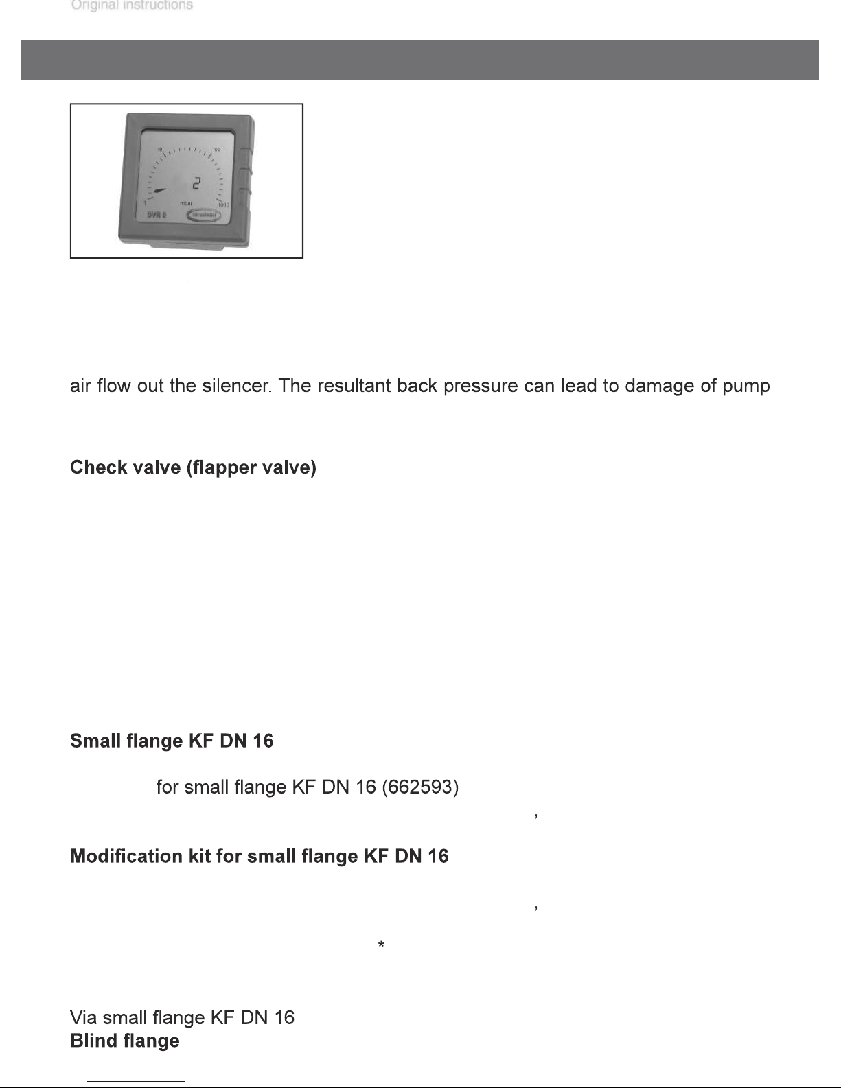
Accessories
for pressure differences > 375 Torr (500 mbar))
.....................
for catchpots
Vacuum hose (caoutchouc)
......................................
for hose nozzle
to two inlets (valve block; replaces distribution head)
Adapter G 1/4 thread to PTFE tubing*
for inlet at valve block (SYNCHRO)
for assembly at inlet of valve block (SYNCHRO)
...........................................
...............................
for inlet at valve block (SYNCHRO)
................................................
...............................
for inlet at distribution head
for assembly at inlet of distribution head
Adapter
for
(C1)
for assembly at valve block or distribution head
Attention
I.D. 3/8” (
3/8” (
for tubing I.D. 1/4” / 3/8” (
for tubing I.D. 1/4” / 3/8” (
Page 44
page 49 of 75
Ways to connect NT chemistry diaphragm pumps:
with hose - for installation at hose nozzle
for assembly directly at the valve head
for assembly directly at the valve head (at outlet of ME 8C NT / MD 4C NT)
Adapter hose nozzle DN 10 to hose nozzle 1/2
.......................................
Adapter to PTFE tubing*
for assembly directly at the valve head (at inlet of ME 4C NT / ME 8C NT / MD 4C
Adapter to PTFE tubing*
for assembly directly at the valve head (at inlet of MZ 2C NT;
.......................................
(sold by meter)
(C2)
for assembly at valve block or distribution head
(C3-B)
for assembly at valve block or distribution head
for assembly at valve block or distribution head
®
Mini-Network
.........................
0.52 qt (500 ml), coated
at the spherical ground joint of the catchpot.................
PTFE tubing DN 10/8 mm
®
®
modules, pumps and connectors
Page 45
vacuum or usual
vacuum system?
Allow pump to run for
formed inside the
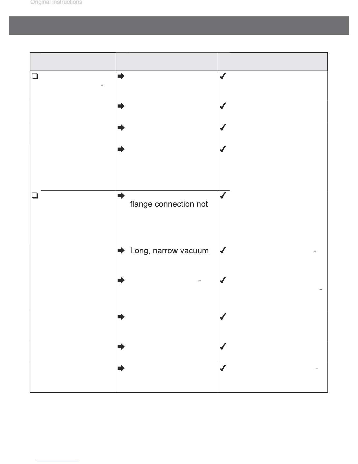
Troubleshooting
Electrical power cord
not plugged in, electrical supply failure?
Device fuse blown? Identify cause of failure.
Overpressure in outlet
line?
Motor overloaded? Allow motor to cool down,
Plug in power cord.
Check fuse.
Replace device fuse.
Remove blockage in line,
open valve.
identify and eliminate
cause of failure. Manual
reset is necessary. Switch
off pump or unplug.
Page 46
page 51 of 75
Atmospheric or high
to pump outlet. Be careful
tioned causes?
A service manual with exploded view drawings, spare parts list and
Page 47
the pump are disassembled.
after isolating the
tion. Ensure that the pump is decontaminated before
Avoid the release of pollutants.
taminated the pump and may be released upon dis
familiar with the safety procedures which relate to the
Vent the pump and isolate it from the vacuum sys
tem before you start maintenance.
Replacing diaphragms and valves
Page 48
page 53 of 75
........................
for cracks or other damage.
NOTICE
Page 49
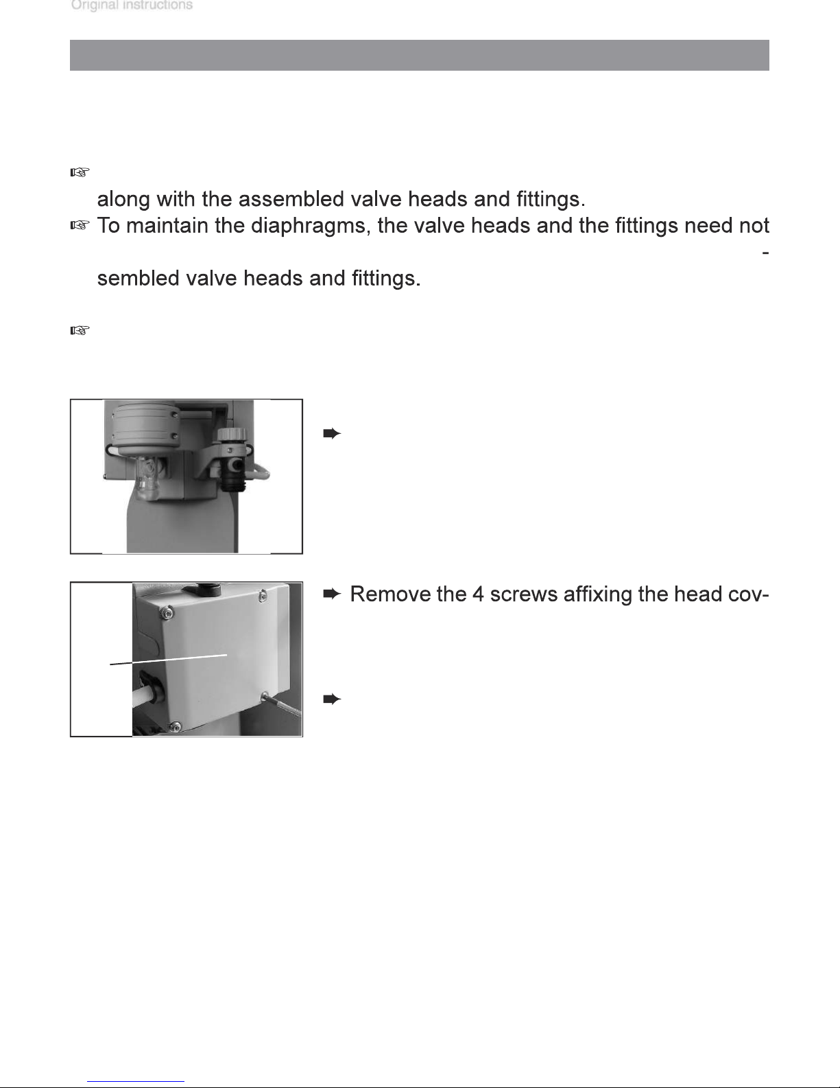
Cleaning and inspecting the pump heads
W
Page 50
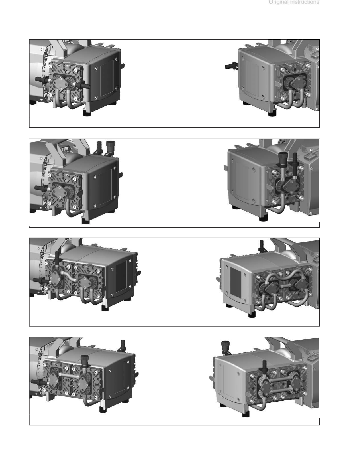
page 55 of 75
Page 51
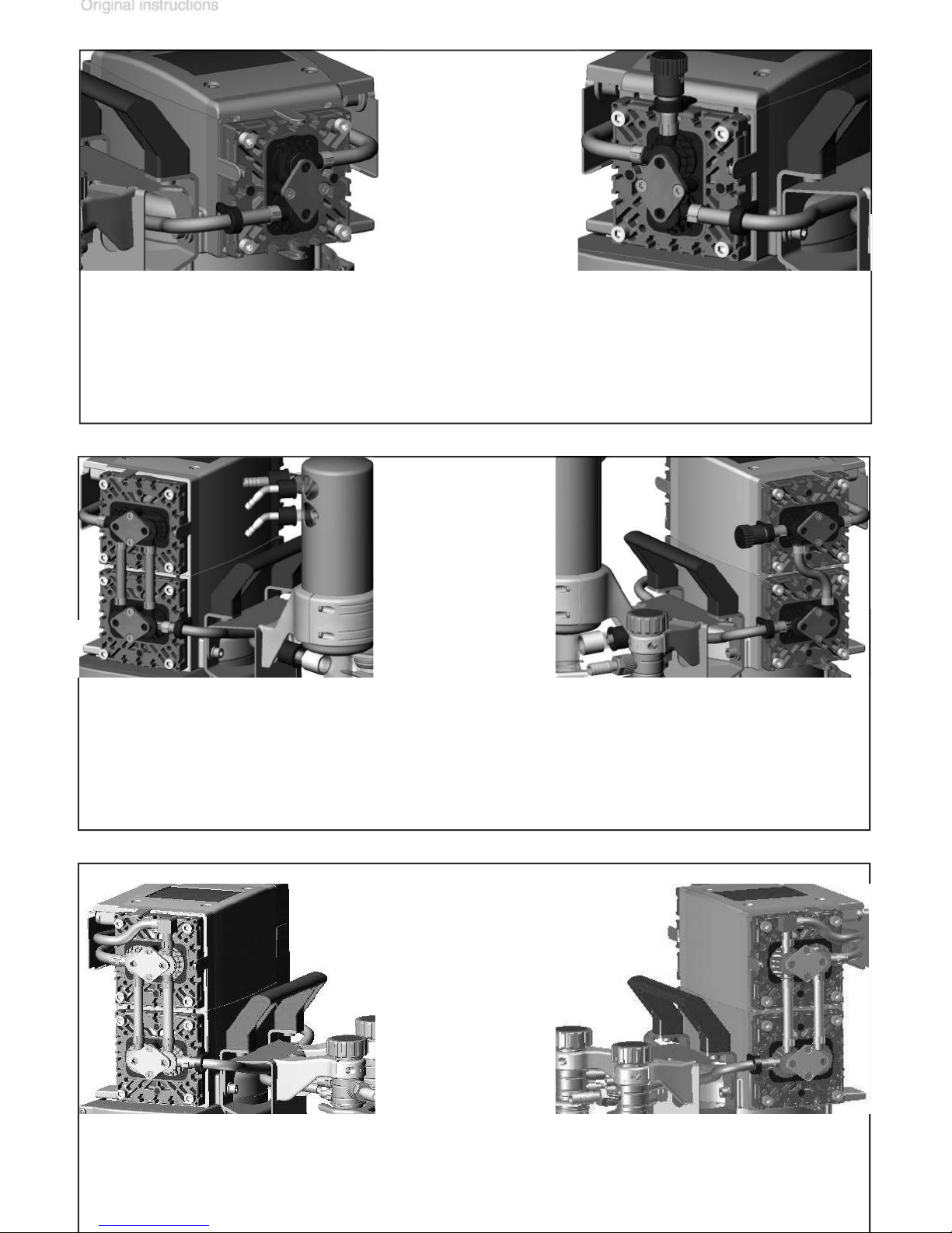
MZ 2C NT AK + EK
Page 52
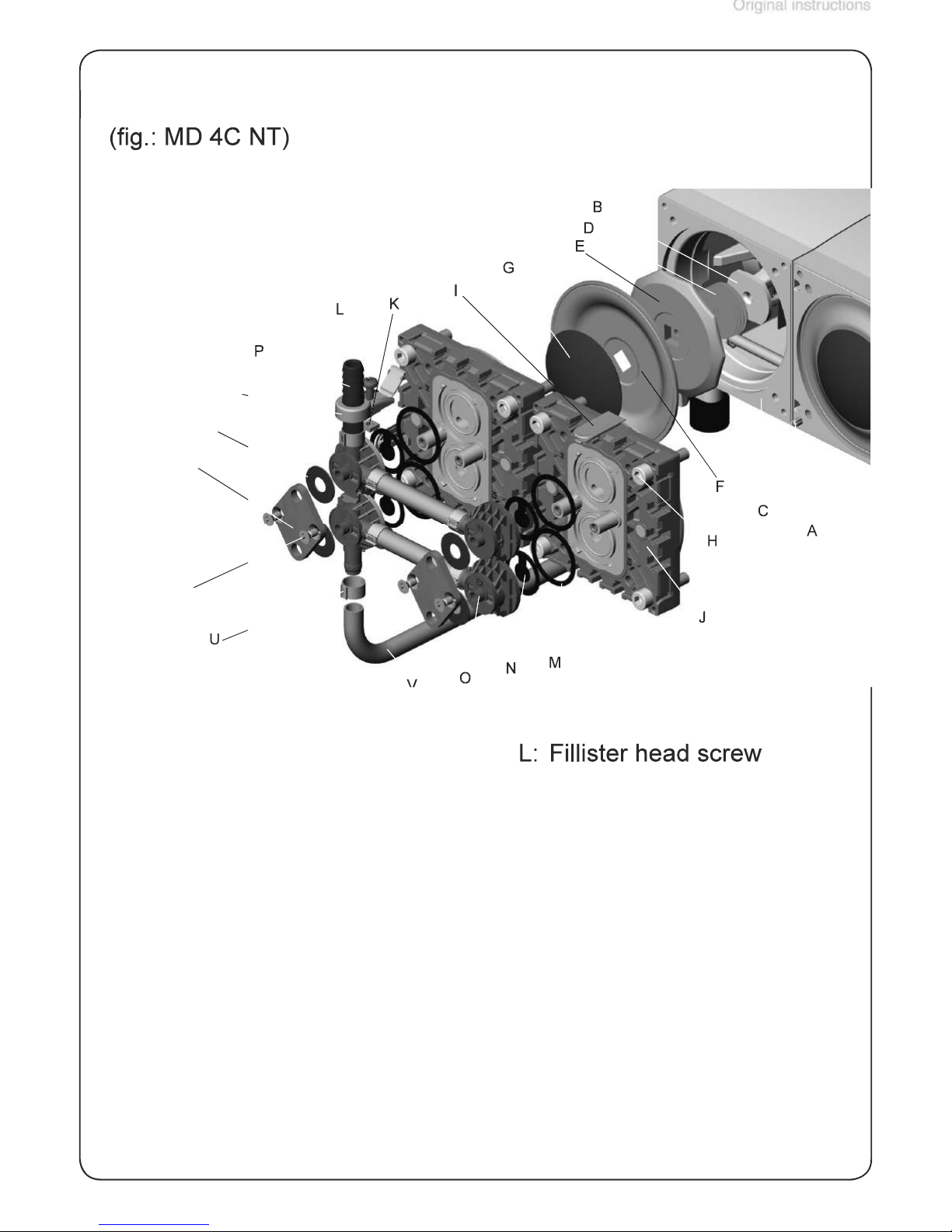
page 57 of 75
V
A:
Washer
with square head screw
Allen screw
I:
Valve head
with hinged cover
V:
Page 53
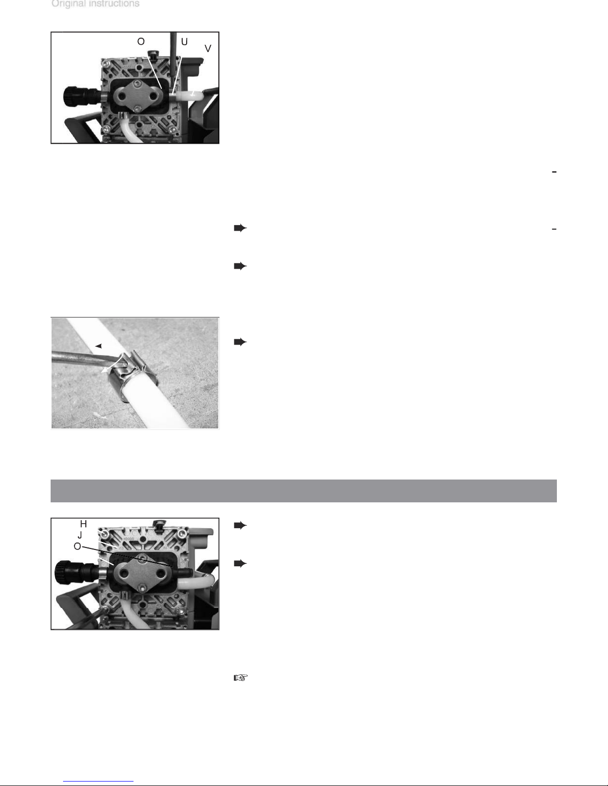
Apply slotted screwdriver as shown and
turn.
valve heads (O) and connections.
the hose connection between the adjacent
Replacing the diaphragm
Page 54
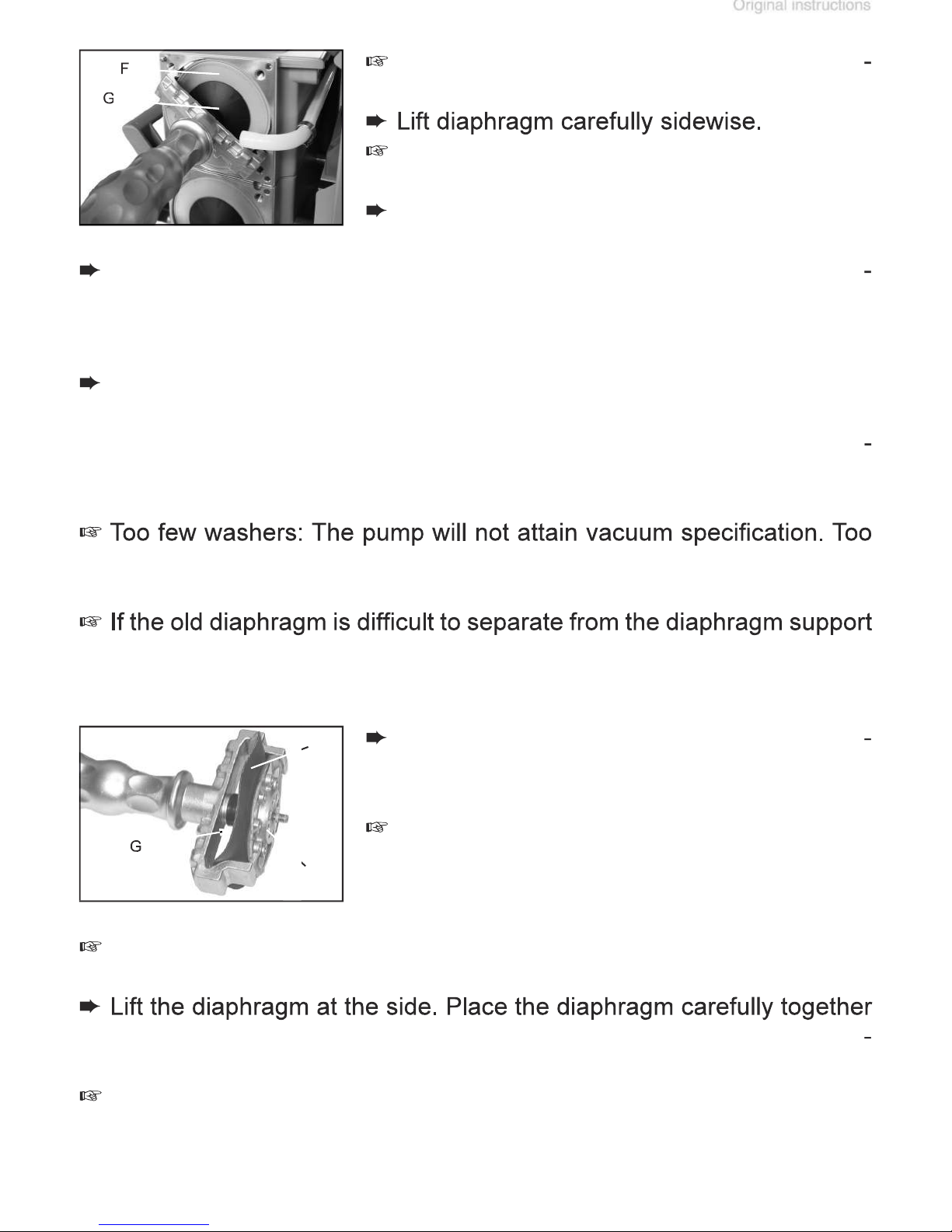
page 59 of 75
towards diaphragm clamping disc (facing
with diaphragm clamping disc and diaphragm support disc in the dia
Avoid damage of the diaphragm: Do not excessively bend or crease
formance. Make sure that the original number is reassembled at the
vapors!
Page 55
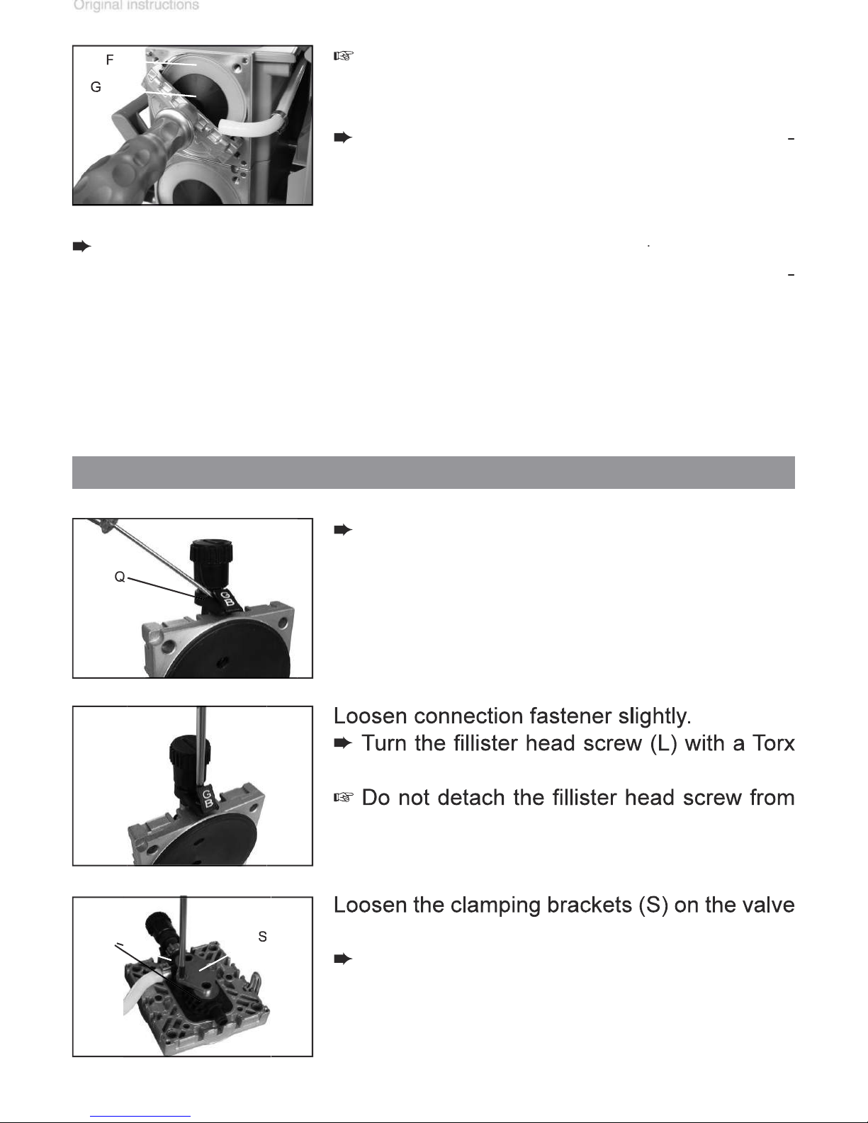
Assemble the original number of washers
f
the square nut (K).
fastener (Q) with a slotted screwdriver.
Replacing the valves
Page 56
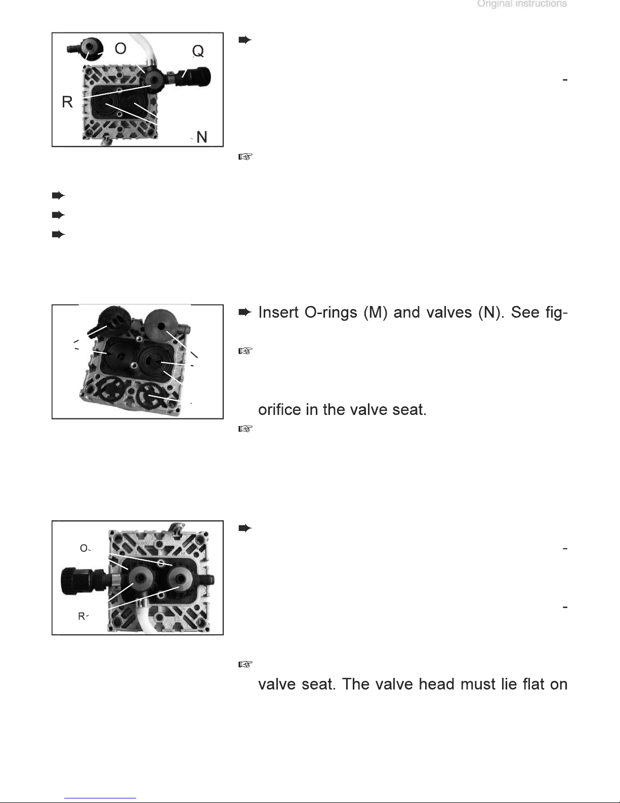
page 61 of 75
valve heads.
valve tongue points at the kidney-shaped
valve is oriented the same direction as the
valve at the inlet side.
with large opening downwards. Pay atten
tion to the correct orientation of the valve
the valve seat.
Page 57
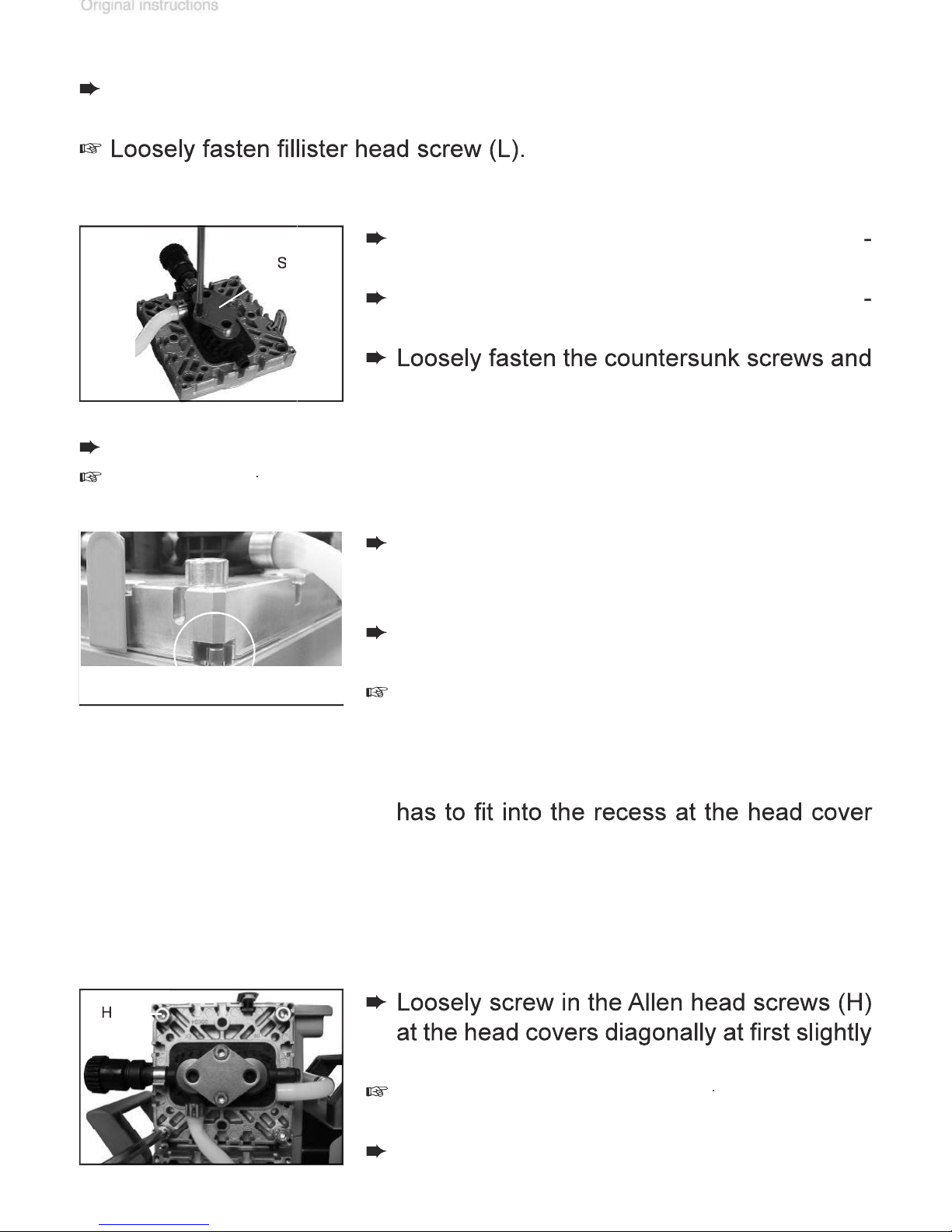
Align the countersunk bores with the thread
f
which they are in contact with the housing
the head covers:
the head cover with the mark at the pump
with a 5 mm wide Allen key, then tighten.
f
Valve head with gas ballast or hose nozzle connection:
Page 58
page 63 of 75
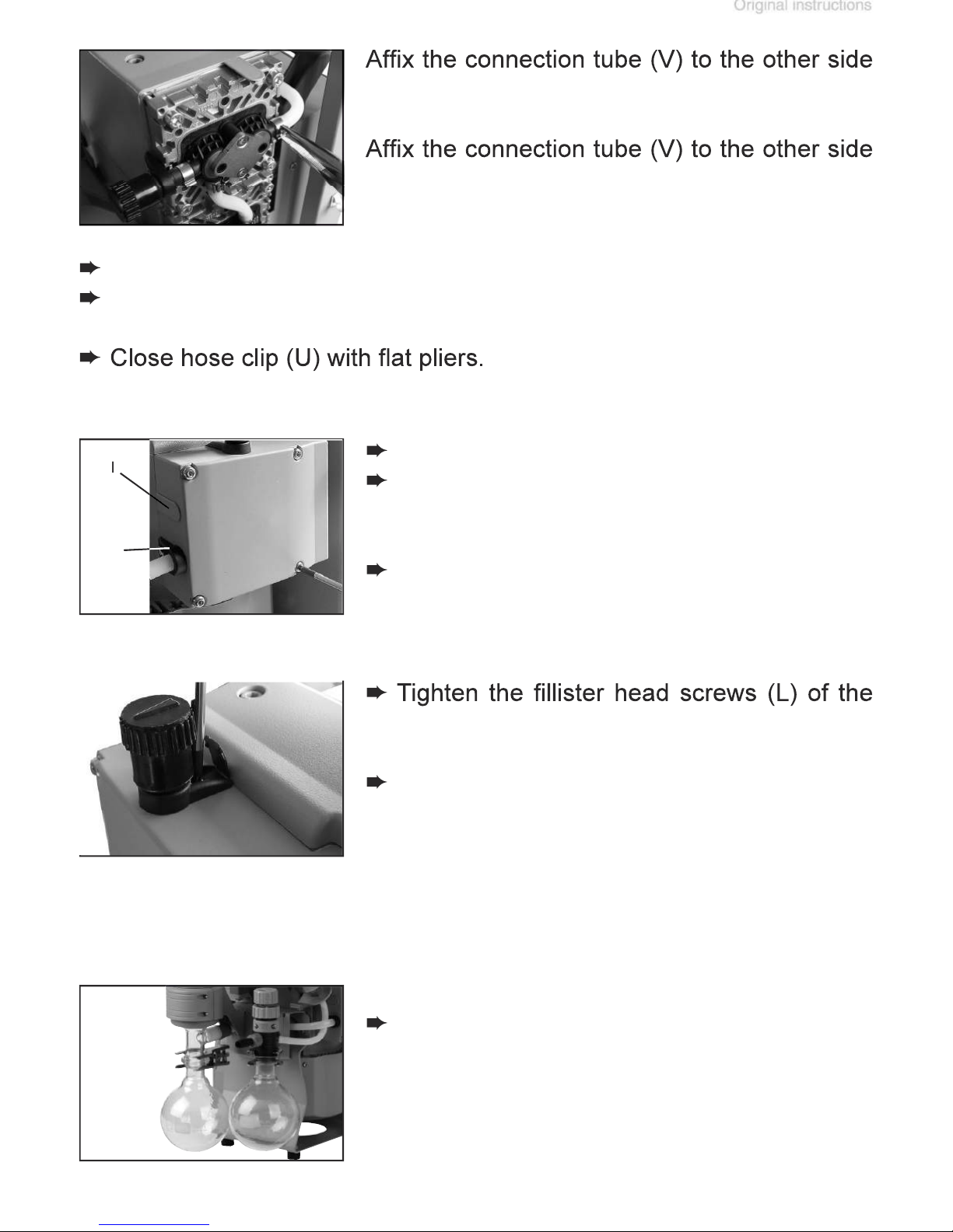
Assemble catchpots (9) with joint clips.
fasteners (Q).
valve head.
Page 59
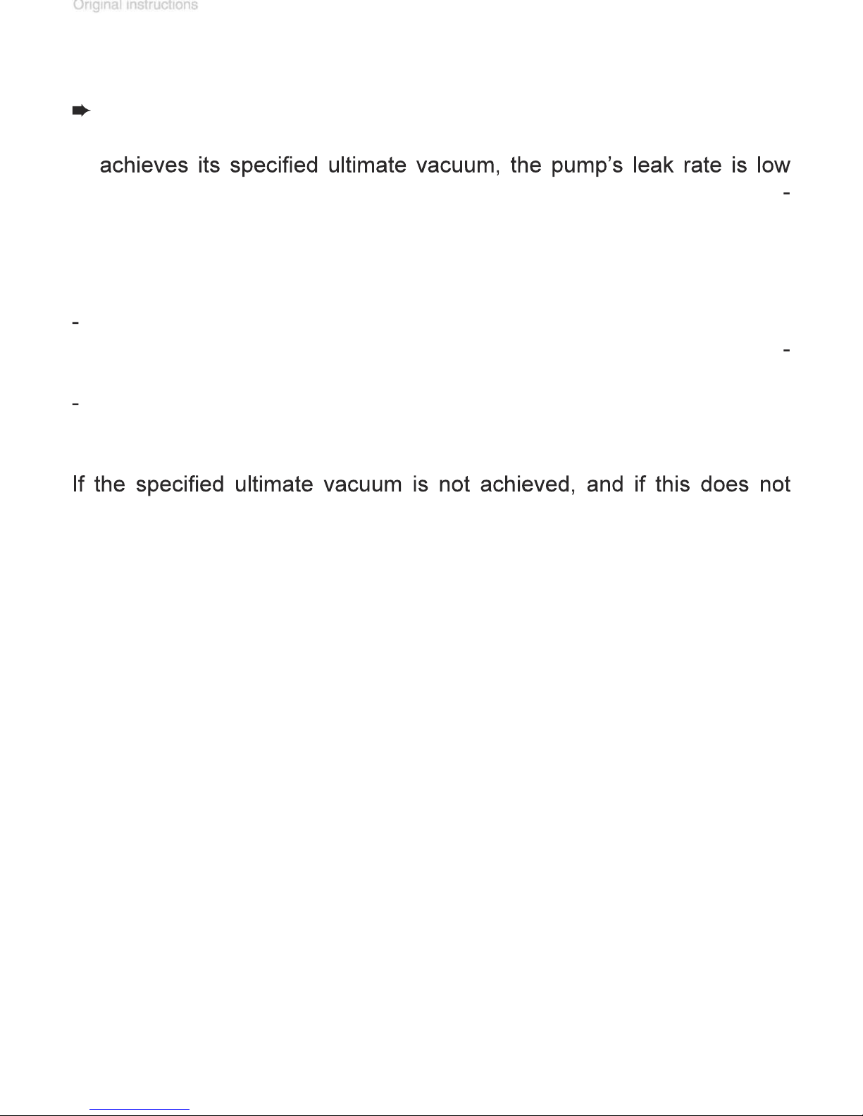
Whenever the diaphragms and valves have been replaced, a break-in
valve seats and pump chambers.
After any intervention at the equipment (e.g., repair / maintenance)
Page 60
page 65 of 75
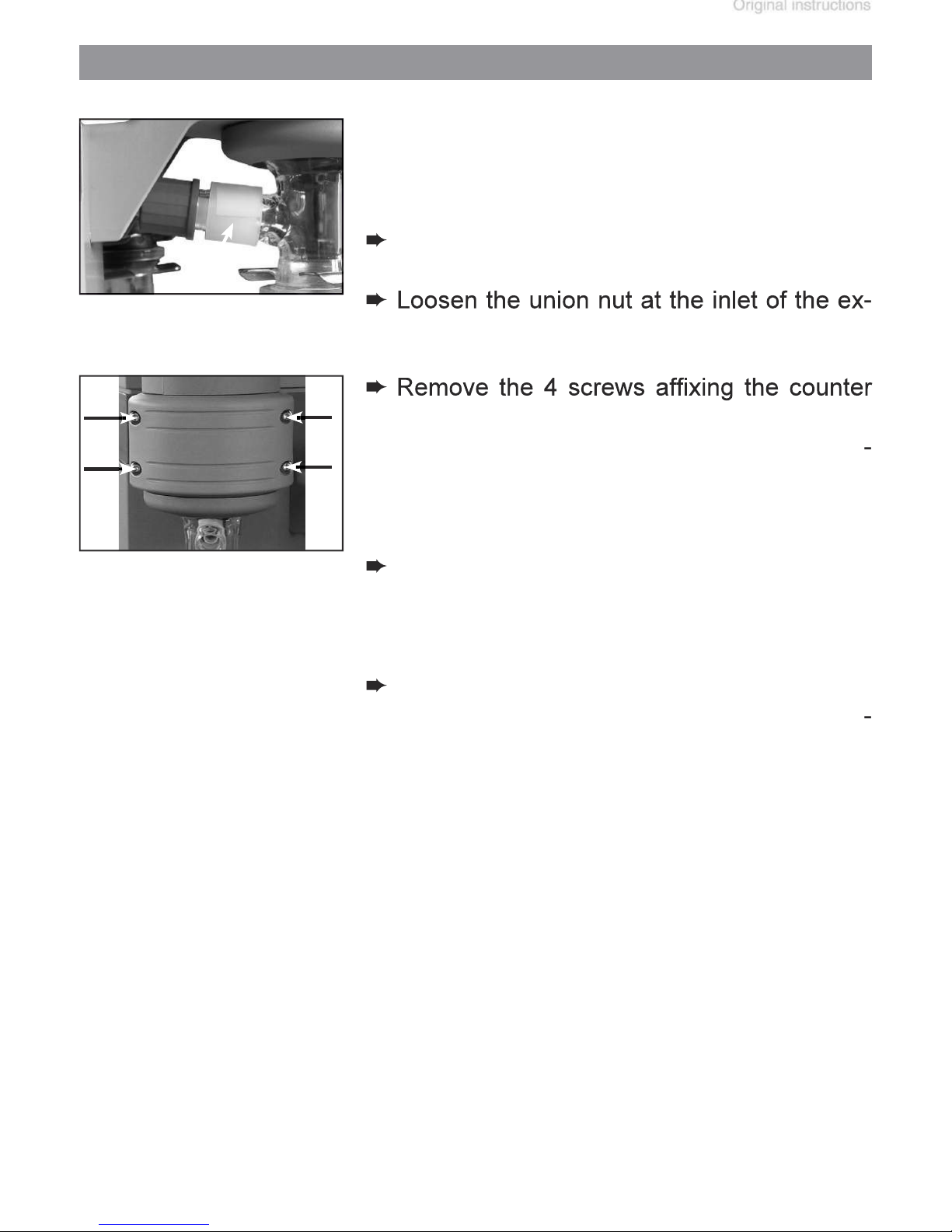
valve and install the new one. Check for
Replacing the overpressure safety relief device
Page 61
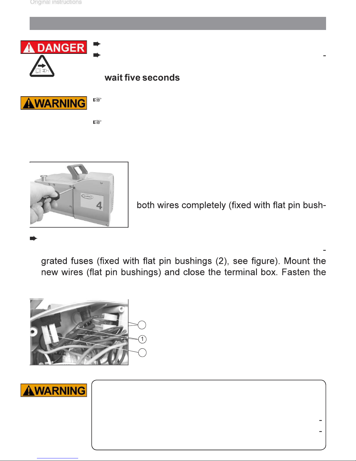
Replacing the fuse
before open
to allow the capacitors to discharge.
trained electrician.
After replacing the fuse, the pump must be checked for
Page 62
page 67 of 75
Repair - Maintenance - Return - Calibration
informs the con
forms the basis for the risk assessment.
These devices cannot be checked, maintained or re
VACUUBRAND due to a residual risk.
Send a completed copy of the
to us in advance. The declaration
Close all openings airtight
Page 63
factory prior to repair.
form.
from it safely in accordance with all local and national
Page 64
page 69 of 75
VACUUBRAND shall be liable for insuring that this prod
fects at the time of the transfer of risk.
VACUUBRAND shall not be liable for the consequences
wearing parts such as diaphragms, seals, valves, vanes,
for damages irrespective of legal grounds.
Warranty
Page 65
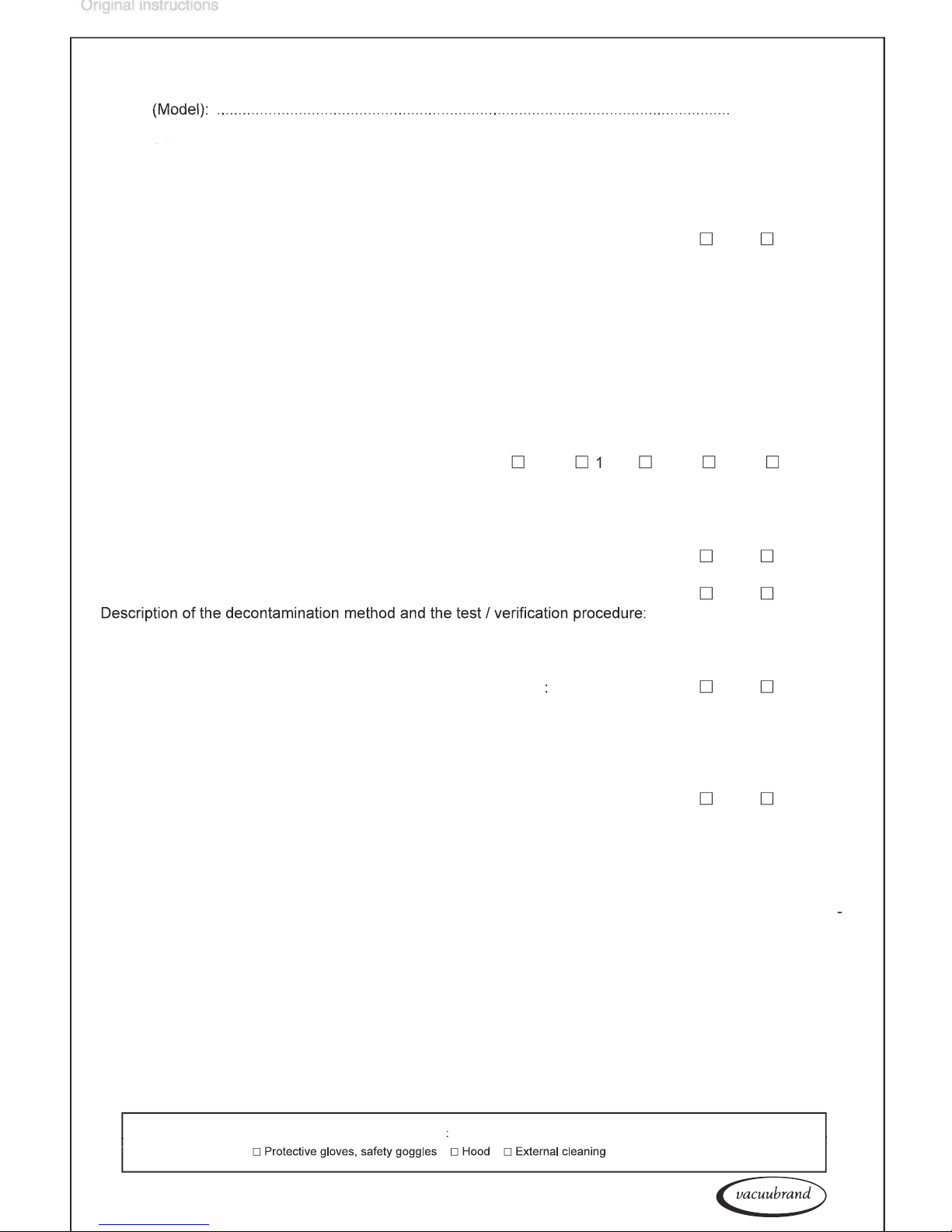
Health and safety clearance form
4.
yes
no
which have been pumped:
4**
which have been
in contact
with biological substances of
tained or repaired. Also decontaminated devices must not returned to VACUUBRAND due to a residual risk.
yes
no
yes
no
All parts of the device are free of hazardous, harmful substances
yes
no
yes
no
We assure for the returned device that all substances, which have been in contact with the device are listed in
from third parties. We are aware that as expressed in § 823 BGB (Public Law Code of Germany) we are directly
Job title: ...................................................................
Protective measures:
VACUUBRAND GMBH + CO KG
Alfred-Zippe-Straße 4
T +49 9342 808-5660 F +49 9342 808-5666
www.vacuubrand.com
Page 66
page 71 of 75
VACUUBRAND GMBH + CO KG · Alfred-Zippe-Str. 4 · 97877 Wertheim · Germany
AK
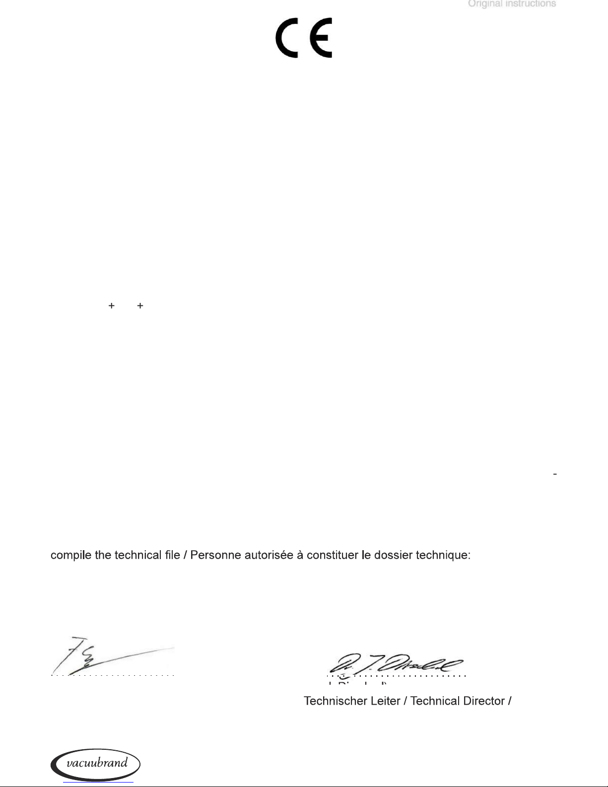
/ ME 8C NT / ME 8C NT + 2 AK / MD 4C NT / MD 4C NT + 2 AK / MD 4C NT + AK + EK /
Artikelnummer / Order number / Numéro d‘article: 730100, 730102, 730105 / 731200, 731201,
Angewandte harmonisierte Normen / Harmonized standards applied / Normes harmonisées uti
Wertheim, 07.07.2017
VACUUBRAND GMBH + CO KG
Alfred-Zippe-Str. 4 · 97877 Wertheim
Page 67
Page 68
page 73 of 75
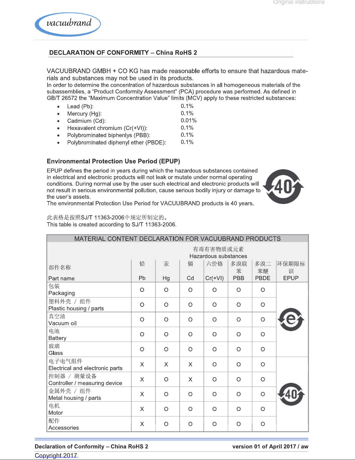
China RoHS
Page 69
Page 70

page 75 of 75
factors beyond our control. It is, therefore, strictly the users’ responsibil
VACUUBRAND GMBH + CO KG
© 2017 VACUUBRAND GMBH + CO KG Printed in Germany
Alfred-Zippe-Str. 4 · 97877 Wertheim / Germany
 Loading...