

Page 1
user's manual
brake chopper unit (bcu)
application
24-hour support +358 (0)40 837 1150 • Email: vacon@vacon.com
9
Page 2

2 • vacon
Vacon Brake Chopper Unit application
Software: ABFIFF01 V1.01
INDEX Document code: ud01138a
Date: 1.11.2006
1. INTRODUCTION .................................................................................................................................3
1.1 Operation principle of BCU....................................................................................................... 3
1.2 Quick start instructions ............................................................................................................ 5
2. CONTROL I/O ...................................................................................................................................6
3. BRAKE CHOPPER APPLICATION – PARAMETER LISTS ........................................................................... 7
3.1 Monitoring values (Control keypad: menu M1)........................................................................ 7
3.2 Basic parameters (Control keypad: Menu G2 Æ G2.1)............................................................ 8
3.3 Input signals (Control keypad: Menu G2 Æ G2.2).................................................................... 8
3.4 Output signals (Control keypad: Menu G2 Æ G2.3) ................................................................. 9
3.5 BCU In parallel (Control keypad: Menu G2 Æ G2.4)................................................................ 9
3.6 Fieldbus parameters (Control keypad: Menu G2 Æ G2.5)..................................................... 10
3.7 Protections (Menu G2 Æ G2.6) ............................................................................................... 11
3.8 Keypad control (Control keypad: Menu M3)........................................................................... 11
3.9 System menu (Control keypad: Menu M6)............................................................................. 11
3.10 Expander boards (Control keypad: Menu M7) ....................................................................... 11
4. DESCRIPTION OF PARAMETERS.........................................................................................................12
4.1 Basic parameters ................................................................................................................... 12
4.2 Input signals............................................................................................................................ 13
4.3 Output signals......................................................................................................................... 15
4.4 BCU In Parallel ....................................................................................................................... 17
4.5 Fieldbus parameters .............................................................................................................. 17
4.6 Protections.............................................................................................................................. 18
4.7 Keypad control........................................................................................................................ 18
5. FIELDBUS PROFILE FOR VACON BRAKE CHOPPER UNIT ....................................................................... 19
6. FAULT CODES ................................................................................................................................. 21
Tel.+358 (0)201 2121 • Fax +358 (0)201 212 205
Page 3
Introduction vacon • 3
1. INTRODUCTION
1.1 Operation principle of BCU
When you want to slow down a running asynchronous motor fed by a frequency converter it turns
into a generator, feeding energy back into the frequency converter. The energy increases the voltage
in the DC-link. The frequency converter compensates for this increase by increasing the output
frequency, decreasing the instantaneous slip and increasing the motor load. The deceleration is, in
this case, dependent on the power losses in the converter and in the motor. This is usually sufficient
in most cases, for pumps, fans, conveyors etc. where the kinetic energy in the load is small or the
braking time is not critical.
When you have to brake down the motor faster than the losses allow, you have to use BCU module
and an external brake resistor (or resistors) for energy dissipation. The extra energy from the load
is turned into heat in the brake resistor. If the DC link voltage increases too much, the BCU turns on
and discharges the capacitors through the brake resistor. Applications where dynamic braking is
usually needed include centrifuges, cranes, some conveyors and drives requiring very fast
reversing.
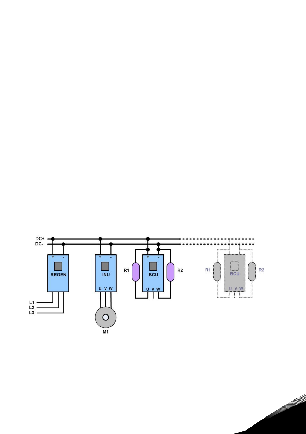
Modules can be connected parallel with other BCU modules in order to increase braking capacity
(Figure 1).
In BCU application you can use either Analogue input or OPT-B8 option board for PT100 sensor
connection.
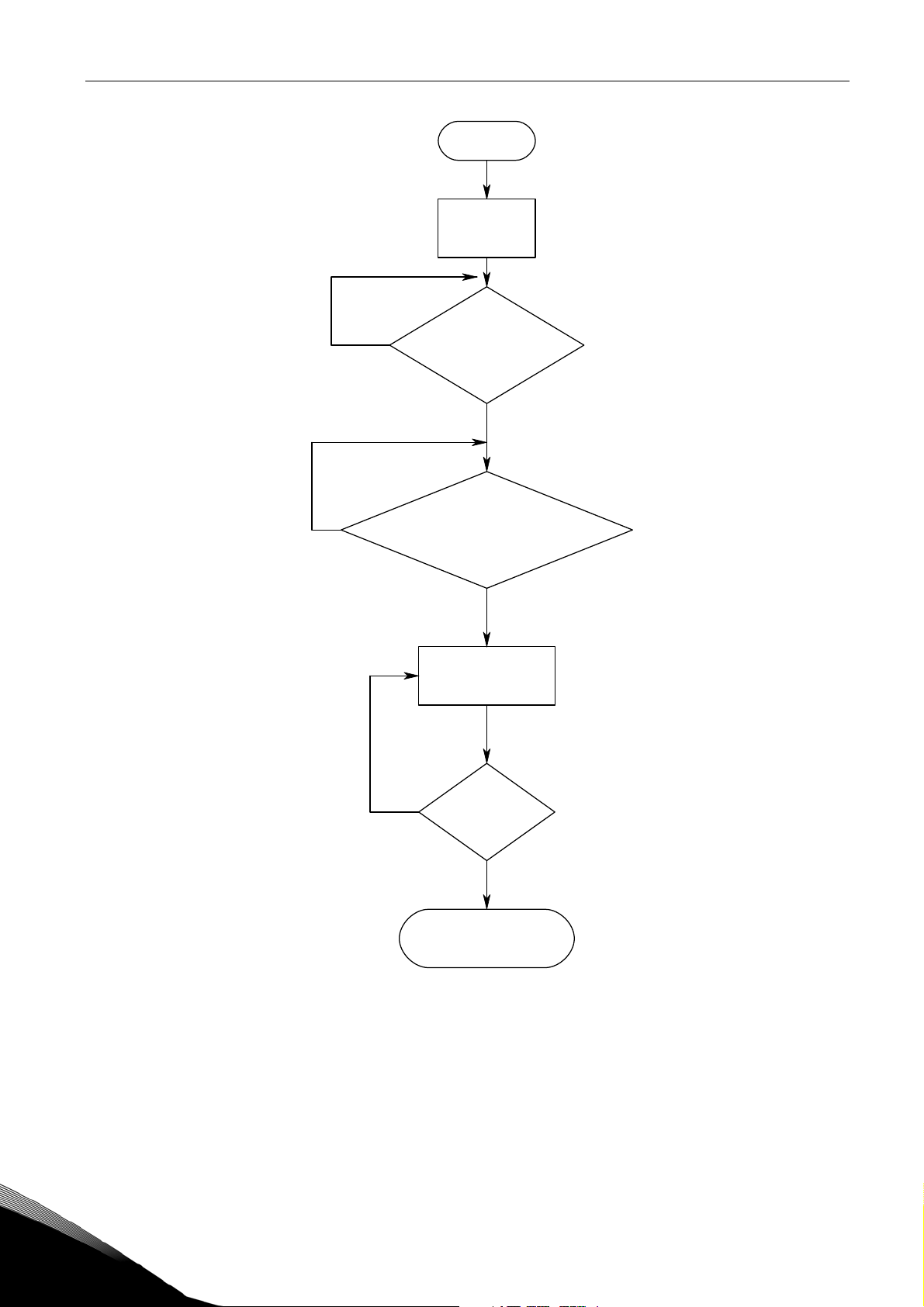
Start-up sequence of BCU application has been illustrated in Figure 2.
Figure 1. BCU in common DC bus system
24-hour support +358 (0)40 8371 150 • Email: vacon@vacon.com
Page 4
4 • vacon Introduction
Init
Softwar e Ini t
complete
Read y to
switch on
DC link voltage
OK?
No
Yes
RunEna ble from I/O (P2.2.1.3)
No
or fieldbus (MCW,bit 1)
Ready to Run
(Ready led is on)
Fault?
Yes
BCU Ru nning
(Run le d is on )
Figure 2. Start-up sequence
Yes
No
Tel.+358 (0)201 2121 • Fax +358 (0)201 212 205
Page 5
Introduction vacon • 5
1.2 Quick start instructions
NOTE! Before taking any commissioning actions read carefully the safety instructions in Vacon NX
User's Manual, chapter 1.
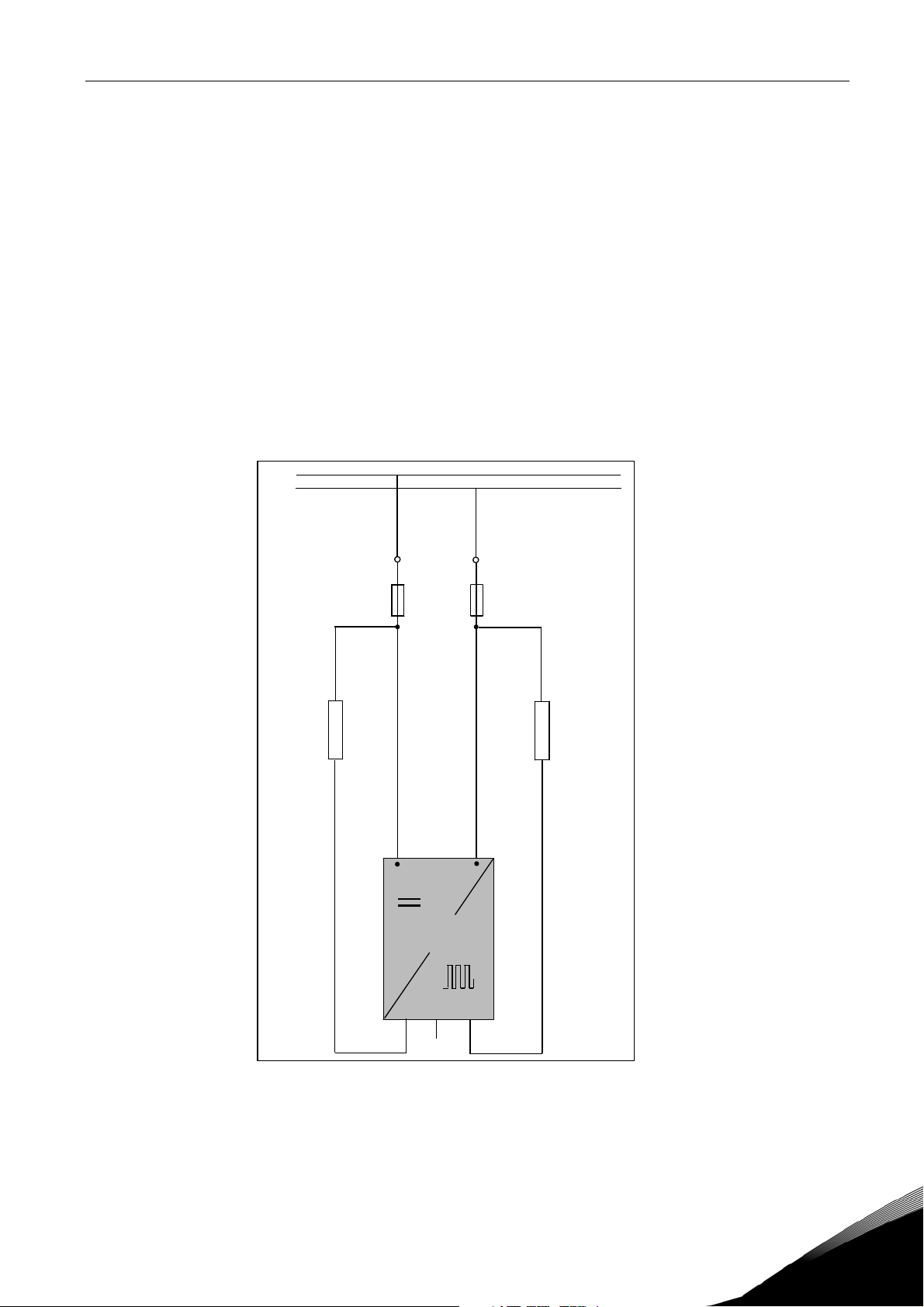
1. Check installations (see Figure 3, Table 2-1 and Table 2-2).
2. Check resistor(s) max. temperature durability.
3. Switch power on.
4. Set PT-100 parameters (P2.2.2.1, P2.2.2.2 and P2.6.1 – P2.6.3) or KLIXON input settings
(P2.2.1.4).
5. Set brake chopper operation level to preferred value (P2.1.2).
6. In case of parallel BCU set Drooping (P2.4.1) = 5%.
7. Set Digital input parameters (P2.2.1.1 – P2.2.1.4) according to connections.
8. Test BCU.
9. If fault occurs see chapter 6.
DC+
DC-
-R1
-U1
DC+
-F1
BCU
UVW
DC-
-R2
Figure 3. Resistor connections
24-hour support +358 (0)40 8371 150 • Email: vacon@vacon.com
Page 6
6 • vacon Control I/O
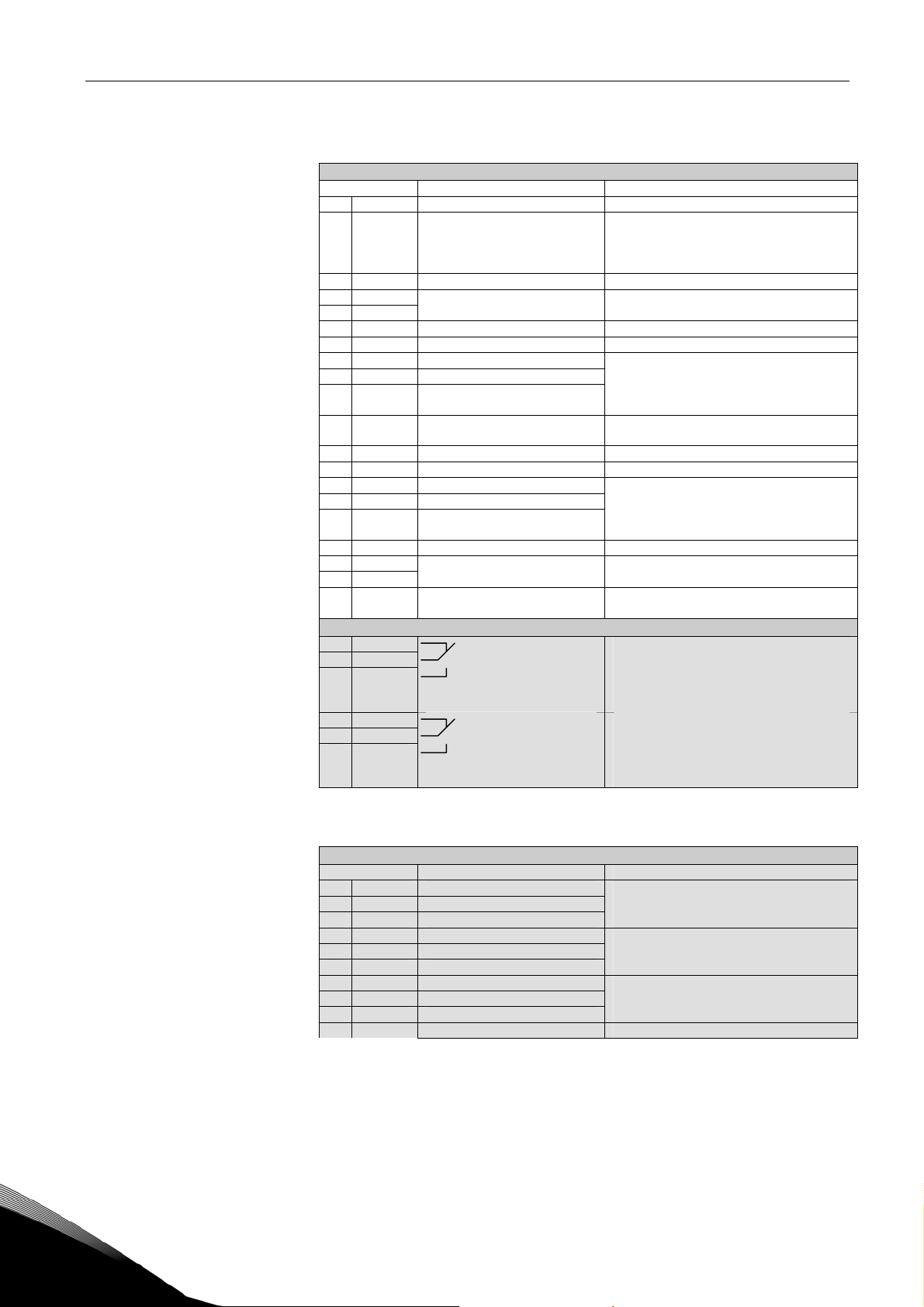
2. CONTROL I/O
OPT-A1
Terminal Signal Description
1 +10V
2 AI1+ Analogue input 1, voltage or
3 AI1- Analogue input common Ground for reference and controls
4 AI2+
5 AI26 +24V Control voltage output Voltage for switches, etc. max 0.1 A
7 GND I/O ground Ground for reference and controls
8 DIN1 Digital input 1
9 DIN2 Digital input 2
10 DIN3 Digital input 3
11 CMA Common for DIN 1—DIN 3 Connect to GND or +24V
12 +24V Control voltage output Voltage for switches (see #6)
13 GND I/O ground Ground for reference and controls
14 DIN4 Digital input 4
15 DIN5 Digital input 5
16 DIN6 Digital input 6
17 CMB Common for DIN4—DIN6 Connect to GND or +24V
18 AO1+
19 AO120 DO1 Digital output
Reference voltage Maximum current 10 mA
ref
current
Analogue input 2 Same as A1 but default is 0-20mA.
Fault Reset (Par. P2.2.1.1)
Run enable (Par. P2.2.1.3)
Analogue output 1 Programmable
READY (Par. P2.2.5)
Default: 0– +10V (Ri = 200 kΩ)
(-10V…..+10V Joy-stick control,
selected with a jumper)
0– 20mA (Ri = 250 Ω)
Ri = min. 5kΩ 18…30V = "1"
Ri = min. 5kΩ 18…30V = "1"
.
Range 0—20 mA/R
Programmable
Open collector, I≤50mA, U≤48 VDC
, max. 500Ω
L
OPT-A2
21 RO1
22 RO1
23 RO1
24 RO2
25 RO2
26 RO2
Relay output 1
Running
Relay output 2
Fault
Switching capacity
24VDC/8A
250VAC/8A
125VDC/0.4A
Min. switching load 5V/10mA
Switching capacity
24VDC/8A
250VAC/8A
125VDC/0.4A
Min. switching load 5V/10mA
Table 2- 1. Default I/O configuration.
OPT-B8
Terminal Signal Technical information
1 R1 + AnIN:X.1
2 Rm1
3 R1 -
4 R2 + AnIN:X.2
5 Rm2
6 R2 -
7 R3 + AnIN:X.3
8 Rm3
9 R3 -
10 NC Not connected
PT100 Input, -30…200°C, one sensor.
Accuracy ≤ 1°C.
Sensor current 10 mA.
PT100 Input, -30…200°C, one sensor.
Accuracy ≤ 1°C.
Sensor current 10 mA.
PT100 Input, -30…200°C, one sensor.
Accuracy ≤ 1°C.
Sensor current 10 mA.
Table 2- 2. I/O terminals on OPT-B8
Tel.+358 (0)201 2121 • Fax +358 (0)201 212 205
Page 7

Brake Chopper Application – Parameter lists vacon • 7
3. BRAKE CHOPPER APPLICATION – PARAMETER LISTS
On the next pages you will find the lists of parameters within the respective parameter groups.
Column explanations:
Code = Location indication on the keypad; Shows the operator the present parameter
number
Parameter = Name of parameter
Default = Value preset by factory
Min = Minimum value of parameter
Max = Maximum value of parameter
Unit = Unit of parameter value; given if available
ID = ID number of the parameter (used with PC tools and fieldbus)
Note = Description of parameter
3.1 Monitoring values (Control keypad: menu M1)
The monitoring values are the actual values of parameters and signals as well as statuses and
measurements. Monitoring values cannot be edited.
See Vacon NX User's Manual, Chapter 7 for more information.
Code Parameter Unit ID Note
V1.1 Total Current A 1104 Filtered braking current in Amperes.
V1.2 Power kW 1106 Braking power in kW.
V1.3 DC-link Voltage V 1108 DC intermediate voltage in Volts
V1.4 Unit Temperature °C 1109 Unit temperature C-degrees.
V1.5 ANALOG OUTPUT 1 % 1112 Analog Output 1 in%
V1.6 DIN1, DIN2, DIN3 15 Digital Inputs A1, A2 and A3 Status (sum)
V1.7 DIN4, DIN5, DIN6 16 Digital Inputs B4, B5 and B6 Status (sum)
V1.8 DO1, RO1, RO2 17 Digital Output and Relay 1&2 Status (sum)
V1.9 Unit Nom Voltage V 111 Nominal voltage rating of the Frequency
V1.10 Unit Nom Current A 1118 Nominal current rating of Frequency Converter.
V1.11 DC Nom Voltage V 1120 Nominal value of Dc-link voltage in Volts.
V1.12 MainControlWord 1160 See the chapter 5
V1.13 MainStatusWord 1162 See the chapter 5
V1.14 Active Fault 37 Active fault code
V1.15 PT100(1) Temperature °C 50 Temperature measured with PT100 sensor 1
V1.16 PT100(2) Temperature °C 51 Temperature measured with PT100 sensor 2
V1.17 PT100(3) Temperature °C 52 Temperature measured with PT100 sensor 3
Table 3-1. Monitoring values
Converter.
(only when OPT-B8 is used)
(only when OPT-B8 is used)
24-hour support +358 (0)40 8371 150 • Email: vacon@vacon.com
Page 8

8 • vacon Brake Chopper Application – Parameter lists
3.2 Basic parameters (Control keypad: Menu G2 Æ G2.1)
Code Parameter Default Min Max Unit ID Note
P2.1.1
P2.1.2 ID Run 0 0 1 631
BrkChopper
Level
648
BrakeChopperLev
elMin
BrakeChopperLev
elMax
V 1267
Brake chopper operation
level in volts
Manual identification for
brake resistor connection.
Table 3-2. Basic parameters G2.1
3.3 Input signals (Control keypad: Menu G2 Æ G2.2)
3.3.1 Digital inputs (G2.2.1)
Code Parameter Default Min Max Unit ID Note
Input Selection for Fault
Resetting.
0 = Not used
1 = DIN1
P2.2.1.1 Fault Reset 3 0 6 1208
P2.2.1.2 External Fault 0 0 6 1214
P2.2.1.3 Run Enable 6 0 6 1212
P2.2.1.4 KLIXON 0 0 6 1209
Table 3-3. Digital input parameters G2.2.1
2 = DIN2
3 = DIN3
4 = DIN4
5 = DIN5
6 = DIN6
Digital input selection for
external fault signal
connection.
As par. P2.2.1.1
Input selection for Run
Enable Ctrl. 0 = Run
Enabled internally
As par. P2.2.1.1
Input Selection for KLIXON
type Temperature Sensor.
As par. P2.2.1.1
3.3.2 Analog inputs (G2.2.2)
Code Parameter Default Min Max Unit ID Note
Select the Analog input for
P2.2.2.1
P2.2.2.2 PT100 In Series 0 0 2 1222
PT100 Analog Input
selection
0 0 2 1221
connecting PT100 Sensor.
0=Not Used,
1=AI1,
2=AI2
Number of PT100 elements in
series.
0=1*PT100,
1=2*PT100,
2=3*PT100.
Table 3-4. Analog input parameters G2.2.2
Tel.+358 (0)201 2121 • Fax +358 (0)201 212 205
Page 9

Brake Chopper Application – Parameter lists vacon • 9
3.4 Output signals (Control keypad: Menu G2 Æ G2.3)
3.4.1 Digital outputs (G2.3.1)
Code Parameter Default Min Max Unit ID Note
P2.3.1.1 DO1 Ctrl 1 0 6 1216 Signal Selection for DO1
P2.3.1.2 DO2 Ctrl 2 0 6 1217 Signal selection for DO2 (RO1)
P2.3.1.3 DO3 Ctrl 3 0 6 1218 Signal selection for DO3 (RO2)
P2.3.1.4 DO4 Ctrl 0 0 6 1385 Signal Selection for DO4
P2.3.1.5 DO5 Ctrl 0 0 6 1386 Signal selection for DO5
P2.3.1.6 DO6 Ctrl 0 0 6 1390 Signal selection for DO6
P2.3.1.7 DO7 Ctrl 0 0 6 1391 Signal Selection for DO7
P2.3.1.8 DO8 Ctrl 0 0 6 1395 Signal selection for DO8
P2.3.1.9 DO9 Ctrl 0 0 6 1396 Signal selection for DO9
P2.3.1.10 DO10 Ctrl 0 0 6 1423 Signal Selection for DO10
P2.3.1.11 DO11 Ctrl 0 0 6 1427 Signal selection for DO11
P2.3.1.12 DO12 Ctrl 0 0 6 1428 Signal selection for DO12
P2.3.1.13 DO13 Ctrl 0 0 6 1429 Signal selection for DO13
Table 3-5. Digital output parameters G2.3.1
3.4.2 Analog output 1 (G2.3.2)
Code Parameter Default Min Max Unit ID Note
P2.3.2.1 AO1 Signal ID 0 0 2000 1233
P2.3.2.2 AO1 Offset 0 0 1 1234
P2.3.2.3 AO1 Filter 10 0,02 10,00 s 1235
P2.3.2.4 AO1 Max. Value 1500 -30000 30000 1236
P2.3.2.5 AO1 Min. Value 0 -30000 30000 1237
Set the ID no. of a signal to be
connected to AO1
Minimum voltage or current
at AO1. 0= 0V/0mA, 1= 4mA
Filter time for the signal
selected for AO1 in Seconds.
Maximum value of a signal
selected for AO1. This will
correspond to +10V/20mA.
Minimum value of a signal
connected to AO1. This will
correspond to 0V/0mA or
2V/4mA depending on the
type of AO1.
Table 3-6. Analog output parameters G2.3.2
3.5 BCU In parallel (Control keypad: Menu G2 Æ G2.4)
Code Parameter Default Min Max Unit ID Note
P2.4.1 Drooping 0 0,00 100,00 % 620
Table 3-7. BCU In Parallel parameters G2.4
Increase in braking current
will increase the DC link
voltage level for operation as
a function of drooping.
24-hour support +358 (0)40 8371 150 • Email: vacon@vacon.com
Page 10

10 • vacon Brake Chopper Application – Parameter lists
3.6 Fieldbus parameters (Control keypad: Menu G2 Æ G2.5)
Code Parameter Default Min Max Unit ID Note
P2.5.1
P2.5.2
P2.5.3
P2.5.4
P2.5.5
P2.5.6
P2.5.7
P2.5.8
P2.5.9
P2.5.10
P2.5.11
P2.5.12
P2.5.13
P2.5.14
P2.5.15
P2.5.16
Fieldbus data out 1
selection
Fieldbus data out 2
selection
Fieldbus data out 3
selection
Fieldbus data out 4
selection
Fieldbus data out 5
selection
Fieldbus data out 6
selection
Fieldbus data out 7
selection
Fieldbus data out 8
selection
Fieldbus data in 1
selection
Fieldbus data in 2
selection
Fieldbus data in 3
selection
Fieldbus data in 4
selection
Fieldbus data in 5
selection
Fieldbus data in 6
selection
Fieldbus data in 7
selection
Fieldbus data in 8
selection
1104 0 65535 1490
1106 0 65535 1491
37 0 65535 1492
0 0 65535 1493
0 0 65535 1494
0 0 65535 1495
0 0 65535 1496
0 0 65535 1497
0 0 10000 876
0 0 10000 877
0 0 10000 878
0 0 10000 879
0 0 10000 880
0 0 10000 881
0 0 10000 882
0 0 10000 883
Choose monitoring data with
parameter ID
Choose monitoring data with
parameter ID
Choose monitoring data with
parameter ID
Choose monitoring data with
parameter ID
Choose monitoring data with
parameter ID
Choose monitoring data with
parameter ID
Choose monitoring data with
parameter ID
Choose monitoring data with
parameter ID
Choose controlled data with
parameter ID
Choose controlled data with
parameter ID
Choose controlled data with
parameter ID
Choose controlled data with
parameter ID
Choose controlled data with
parameter ID
Choose controlled data with
parameter ID
Choose controlled data with
parameter ID
Choose controlled data with
parameter ID
Table 3-8. Fieldbus parameters G2.5
Tel.+358 (0)201 2121 • Fax +358 (0)201 212 205
Page 11

Brake Chopper Application – Parameter lists vacon • 11
3.7 Protections (Menu G2 Æ G2.6)
Code Parameter Default Min Max Unit ID Note
Number of PT100
inputs in use at OPT-
P2.6.1 PT100 Numbers 0 0 3 739
P2.6.2 PT100 Alarm Lim 110 -30 200 °C 1347
PT100
P2.6.3 PT100 Fault Lim 120
P2.6.4 Thermistor 1 0 2 1351
P2.6.5 External Fault 2 0 2 701
Alarm
limit
(P2.6.2)
300 °C 1348
B8 option board.
Visible only when the
option board has
been installed
Select the
temperature for PT100
sensor above which
PT100 alarm is
generated in the drive.
Select the
temperature for PT100
sensor above which
PT100 fault is
generated in the drive
Response to
thermistor
overtemperature.
0=No Action,
1=Warning,
2=Fault
Response to External
fault.
0=No action,
1=Warning,
2=Fault
Table 3-9. Protections G2.6
3.8 Keypad control (Control keypad: Menu M3)
Code Parameter Default Min Max Unit ID Description
P3.1 Control place 0 0 1 125
0=I/O terminal (default)
1=Fieldbus
Table 3-10. Keypad control parameters M3
3.9 System menu (Control keypad: Menu M6)
For parameters and functions related to the general use of the frequency converter, such as
application and language selection, customised parameter sets or information about the hardware
and software, see Chapter 7.3.6 in the Vacon NX User's Manual.
3.10 Expander boards (Control keypad: Menu M7)
The M7 menu shows the expander and option boards attached to the control board and boardrelated information. For more information, see Chapter 7.3.7 in the Vacon NX User's Manual.
24-hour support +358 (0)40 8371 150 • Email: vacon@vacon.com
Page 12

12 • vacon Description of parameters
4. DESCRIPTION OF PARAMETERS
4.1 Basic parameters
2.1.1 Brake Chopper Level (ID1267)
Brake chopper operation level in volts. This is the DC link voltage level when the BCU
starts to discharge the capacitors through the brake resistor.
2.1.2 ID Run (ID631)
This parameter is used for manual identification for brake resistor connection. Brake
chopper unit makes automatic identification during every power-up. However, if resistor
connection is changed during service, ID Run can be executed manually with this
parameter by setting the value “1=ID Run”.
Tel.+358 (0)201 2121 • Fax +358 (0)201 212 205
Page 13

Description of parameters vacon • 13
4.2 Input signals
4.2.1 Digital Inputs
2.2.1.1 Fault Reset (ID1208)
Input selection for Fault Resetting. The transition from Off to On will reset the fault if the
cause of the fault has been removed.
0 = Not used
1 = DIN1
2 = DIN2
3 = DIN3
4 = DIN4
5 = DIN5
6 = DIN6
2.2.1.2 External fault (ID1214)
This parameter defines if the BCU monitors status of the External fault input. With
External fault it is possible to trig a fault 51. Response to the fault can be defined with
the parameter P2.6.5.
See parameter P2.2.1.1 for the list of values.
2.2.1.3 Run Enable (ID1212)
This parameter is used for choosing the input for external Run Enable signal. If the
option “0 = Not used” have been selected the Run Enable signal is always on.
See parameter P2.2.1.1 for the list of values.
2.2.1.4 KLIXON Input (ID1209)
This parameter is used for choosing the input for KLIXON type temperature sensor. The
function of this input is Normally Closed so the fault “60 = KLIXON” is generated when
the input goes low.
See parameter P2.2.1.1 for the list of values.
24-hour support +358 (0)40 8371 150 • Email: vacon@vacon.com
Page 14

14 • vacon Description of parameters
4.2.2 Analog Inputs
2.2.2.1 PT100 Analog Input selection (ID1221)
Selects the analogue input to be used for temperature measurement using PT100
sensor.
In BCU application you can use either Analogue input or OPT-B8 option board for PT100
connection. Both ways can not be used at the same time. If Analogue input has been
used for PT100 measurement the Analogue Output 1 is forced to 10mA level and it is
used as a power supply for PT100 sensor. Connection has been illustrated in Figure 4.
0 = Not used
1 = AI1
2 = AI2
AO1+
PT100
AO1-
Figure 4. PT100 connection.
2.2.2.2 PT100 In Series (ID1222)
Selects the number of PT100 elements connected in series.
0 = 1 * PT100
1 = 2 * PT100
2 = 3 * PT100
AI+
AI-
Tel.+358 (0)201 2121 • Fax +358 (0)201 212 205
Page 15

Description of parameters vacon • 15
4.3 Output signals
4.3.1 Digital output signals
2.3.1.1 DO1 (ID1216)
Select the signal for controlling the DO1.
0 = Not used
1 = Ready
2 = Running
3 = Fault
4 = No Fault
5 = Warning
6 = Braking active (BCU is braking)
2.3.1.2 DO2 (ID1217)
Select the signal for controlling the relay output 1 (RO1) of OPT-A2 option board.
See parameter P2.3.1.1 for the list of values.
2.3.1.3 DO3 (ID1218)
Select the signal for controlling the relay output 2 (RO2) of OPT-A2 option board.
See parameter P2.3.1.1 for the list of values.
2.3.1.4-
2.3.1.13 DO4 – DO13 (ID1385 – ID1429)
These parameters are only visible when there are additional option boards with digital
outputs installed in the BCU. If for example the option board OPT-B5 has been installed
the parameters for outputs DO4-DO6 become visible.
See parameter P2.3.1.1 for the list of values.
24-hour support +358 (0)40 8371 150 • Email: vacon@vacon.com
Page 16

16 • vacon Description of parameters
4.3.2 Analogue output 1
2.3.2.1 Analogue Output 1 signal ID (ID1233)
Set the ID no. of a signal to be connected to AO1. To connect e.g. DC-link voltage to
Analog output 1, enter 1108 as parameter value.
NOTE! If Analogue input has been chosen to be used for PT100 measurement (P2.2.2.1 >
0) the Analogue Output 1 is forced to 10mA level.
2.3.2.2 Analogue Output 1 Offset (ID1234)
Minimum voltage or current at AO1.
0 = 0V/0mA,
1 = 4mA
2.3.2.3 Analogue Output Filter time (ID1235)
Defines filtering time of the analogue output signal.
%
Unfiltered signal
100%
Filtered signal
63%
ID1235
Figure 5. Analogue output filtering
2.3.2.4 Analogue Output Maximum value (ID1236)
Maximum value of a signal selected for AO1. This will correspond to +10V/20mA.
2.3.2.5 Analogue Output Minimum value (ID1237)
t [s]
NX12K16
Minimum value of a signal selected for AO1. This will correspond to 0V/0mA or 2V/4mA
depending on the type of AO1.
Tel.+358 (0)201 2121 • Fax +358 (0)201 212 205
Page 17

Description of parameters vacon • 17
4.4 BCU In Parallel
2.4.1 Drooping (ID1501)
Increase in braking current will increase the DC link voltage level for operation as a
function of drooping. This parameter is applicable only when there is more than one BCU
connected in parallel.
4.5 Fieldbus parameters
2.5.1 –
2.5.8 Fieldbus data out 1-8 selection (ID1490-ID1497)
Using these parameters, you can monitor any monitoring or parameter value from the
fieldbus. Enter the ID number of the item you wish to monitor for the value of these
parameters.
2.5.9 –
2.5.16 Fieldbus data in 1-8 selection (ID876-ID883)
Using these parameters, you can control any parameter value from the fieldbus. Enter
the ID number of the item you wish to control for the value of these parameters.
24-hour support +358 (0)40 8371 150 • Email: vacon@vacon.com
Page 18

18 • vacon Description of parameters
4.6 Protections
2.6.1 Number of PT100 inputs in use
If you have a PT100 input board (OPTB8) installed in your BCU you can choose here the
number of PT100 inputs in use. See also the Vacon I/O boards manual.
Note: If the selected value is greater than the actual number of used PT100 inputs, the
display will read 200ºC. If the input is short-circuited the displayed value is –30ºC.
This parameter is visible only when there is OPTB8 option board installed in the
BCU.
2.6.2 PT100 Alarm limit (ID1347)
Set here the limit at which the PT100 alarm will be activated.
2.6.3 PT100 Fault limit (ID1348)
Set here the limit at which the PT100 fault will be activated.
2.6.4 Response to thermistor fault (ID1351)
0 = No response
1 = Warning
2 = Fault
Setting the parameter to 0 will deactivate the protection.
2.6.5 Response to External fault (ID1351)
0 = No response
1 = Warning
2 = Fault
This parameter defines a response to an external fault. If the BCU monitors state of the
external fault input (value of P2.2.1.2 > 0) and a fault occurs the drive can be set to
respond to the fault.
4.7 Keypad control
3.1 Control place (ID125)
The active control place can be changed with this parameter.
0 = I/O terminal (default)
1 = Fieldbus
Tel.+358 (0)201 2121 • Fax +358 (0)201 212 205
Page 19

Fieldbus Profile for Vacon brake chopper unit vacon • 19
5. FIELDBUS PROFILE FOR VACON BRAKE CHOPPER UNIT
Following document describes fieldbus profile for Brake Chopper Unit application.
If Profibus, Modbus or CANopen is used then Operate Mode = Bypass is to be used to be able to
read or write the following info.
Signals from Overriding System to Vacon regenerative Drive.
Fieldbus Data Name
Control Word
Reference Value
Process Data IN1
Process Data IN2
Process Data IN3
Process Data IN4
Process Data IN5
Process Data IN6
Process Data IN7
Process Data IN8
Signal
Name Min Max
Main
Control
Word
See bitwise description below
Reserved for future use.
Reserved for future use.
Reserved for future use.
Reserved for future use.
Reserved for future use.
Reserved for future use.
Reserved for future use.
Reserved for future use.
Reserved for future use.
FB
Scale Scaling Description
Table 5-1. Signals from overriding system
Signals from Vacon Drive to Overriding system
FB
Fieldbus Data Name Signal Name
Main Status Word Main Status Word See bitwise description below
Actual Value DC Voltage 1=1V DC Voltage in Volts
ProcessDataOut1 Total current 10=1A Total Current
ProcessDataOut2 Power 10=1% Power
ProcessDataOut3 Active fault Active Fault
ProcessDataOut4 Reserved for future use.
ProcessDataOut5 Reserved for future use.
ProcessDataOut6 Reserved for future use.
ProcessDataOut7 Reserved for future use.
ProcessDataOut8 Reserved for future use.
Scale Scaling Description
Table 5-2. Signals to overriding system
24-hour support +358 (0)40 8371 150 • Email: vacon@vacon.com
Page 20

20 • vacon Fieldbus Profile for Vacon brake chopper unit
Main Control Word
Bit 0 Reserved for future use.
0=Run is disabled, drive will not go to Run state.
Bit 1 Run Enable
Bit 2 Reserved for future use.
Bit 3 Reserved for future use.
Bit 4 Reserved for future use.
Bit 5 Reserved for future use.
Bit 6 Reserved for future use.
Bit 7 Fault reset 0>1 Reset fault.
Bit 8 Reserved for future use.
Bit 9 Reserved for future use.
Bit 10 Fieldbus Control
Bit 11 Reserved for future use.
Bit 12 Reserved for future use.
Bit 13 Reserved for future use.
Bit 14 Reserved for future use.
Bit 15 Reserved for future use.
1=Run is enabled
0= No control from fieldbus
1=Control from fieldbus
Table 5-3. Main Control Word
Main Status Word
0=Drive is not Ready
Bit 0 Rdy On
Bit 1 Running
Bit 2 Braking Active 1=BCU is braking
Bit 3 Fault
Bit 4 Run Enable
Bit 5 Reserved for future use.
Bit 6 Reserved for future use.
Bit 7 Alarm
Bit 8 Reserved for future use.
Bit 9 Fieldbus Control Active
Bit 10 Reserved for future use.
Bit 11 Reserved for future use.
Bit 12 Reserved for future use.
Bit 13 Reserved for future use.
Bit 14 Reserved for future use.
Bit 15 Reserved for future use.
1=Drive is Ready
0=Drive not running
1=Drive running
0=No active fault
1=Fault is active
0=RunEnable from I/O or fieldbus is
disabled.
1=RunEnable is on.
0=No alarm
1=Alarm active
0=Fieldbus control not active
1=Fieldbus control active
Table 5-4. Main Status Word
Tel.+358 (0)201 2121 • Fax +358 (0)201 212 205
Page 21

Fault codes vacon • 21
6. FAULT CODES
The fault codes, their causes and correcting actions are presented in the table below. The shadowed
faults are A faults only. The items written in white on black background present faults for which you
can program different responses in the application. See parameter group Protections.
Note: When contacting distributor or factory because of a fault condition, always write down all texts
and codes on the keypad display.
Fault
code
1 Overcurrent BCU has detected too high current
2 Overvoltage The DC-link voltage has exceeded the
7 Saturation trip Various causes:
8 System fault
9 Undervoltage DC-link voltage is under the BCU fault
13 BCU under-
14 BCU over-
Fault Possible cause Correcting measures
) in the resistor cables:
(>4*I
H
limit:
911V for 500V BCU
1200V for 690V BCU
− defective component
− brake resistor short-circuit or
overload
- component failure
- faulty operation
Note exceptional fault data record
Subcode in T.14:
S1 = Reserved
S2 = Reserved
S3 = Reserved
S4 = Reserved
S5 = Reserved
S6 = Reserved
S7 = Charging switch
S8 = No power to driver card
S9 = Power unit communication (TX)
S10 = Power unit communication (Trip)
S11 = Power unit comm. (Measurement)
voltage limit:
333VDC for 500V BCU
460VDC for 690V BCU
− most probable cause: too low
supply voltage in the system
− BCU internal fault
Heatsink temperature is under –10°C
temperature
Heatsink temperature is over 90°C
temperature
Overtemperature warning is issued
when the heatsink temperature exceeds
85°C.
- Check cables.
- Check resistors
- Cannot be reset from the keypad.
- Switch off power.
- DO NOT RE-CONNECT POWER!
- Contact your local distributor.
Reset the fault and restart.
Should the fault re-occur, contact your
local distributor. Please visit:
http://www.vacon.com/wwcontacts.html
- In case of temporary supply voltage
break, reset the fault and restart the
frequency converter.
- Check the supply voltage.
- If it is adequate, an internal failure has
occurred.
- Contact your local distributor.
Please visit:
http://www.vacon.com/wwcontacts.html
- Check the correct amount and flow of
cooling air.
- Check the heatsink for dust.
- Check the ambient temperature.
24-hour support +358 (0)40 8371 150 • Email: vacon@vacon.com
Page 22

22 • vacon Fault codes
18 Unbalance
(Warning only)
31 IGBT
temperature
(hardware)
35 Application Problem in application software Contact your distributor. If you are
37 Device changed
(same type)
38 Device added
(same type)
39 Device removed Option board removed. Reset. Device no longer available.
40 Device
unknown
41 IGBT temperature IGBT Inverter Bridge overtemperature
44 Device changed
(different type)
45 Device added
(different type)
51 External fault Digital input fault. - Remove fault situation from external
54 Slot fault Defective option board or slot Check board and slot.
58 PT100 fault Temperature limit values set for the
60 KLIXON Status of KLIXON input is LOW.
61 Thermistor
fault
Unbalance between power modules in
paralleled units.
Subcode in T.14:
S1 = Current unbalance
S2 = DC-Voltage unbalance
IGBT Inverter Bridge overtemperature
protection has detected too high short
term overload current
Option board or power unit changed.
New device of same type and rating.
Option board added.
Unknown option board or drive.
Subcode in T.14:
S1 = Unknown device
S2 = Power1 not same type as Power2
protection has detected too high a short
term overload current
Option board or power unit changed.
New device of different type or different
rating than the previous one.
Option board of different type added. Reset
PT100 have been exceeded.
The thermistor input of option board has
detected too high resistor temperature
Should the fault re-occur, contact your
local distributor.
application programmer check the
application program.
Reset. Device is ready for use.
Old parameter settings will be used.
Reset. Device is ready for use.
Old board settings will be used.
Contact the distributor near to you.
Please visit:
http://www.vacon.com/wwcontacts.html
Reset
Set the option board parameters again if
option bard changed. Set converter
parameters again if power unit changed.
Set the option board parameters again.
device.
Contact the nearest Vacon distributor.
Please visit:
http://www.vacon.com/wwcontacts.html
Check resistors.
Check thermistor connection
(If thermistor input of the option board is
not in use it has to be short circuited)
Table 6-1. Fault codes
Tel.+358 (0)201 2121 • Fax +358 (0)201 212 205
Page 23

Vaasa
Vacon Plc (Head office and production)
Runsorintie 7
65380 Vaasa
firstname.lastname@vacon.com
telephone: +358 (0)201 2121
fax: +358 (0)201 212 205
sales companies and representative offices:
Austria
Vacon AT Antriebssysteme GmbH
Aumühlweg 21
2544 Leobersdorf
telephone: +43 2256 651 66
fax: +43 2256 651 66 66
Belgium
Vacon Benelux NV/SA
Interleuvenlaan 62
3001 Heverlee (Leuven)
telephone: +32 (0)16 394 825
fax: +32 (0)16 394 827
France
Vacon France
ZAC du Fresne
1 Rue Jacquard – BP72
91280 Saint Pierre du Perray CDIS
telephone: +33 (0)1 69 89 60 30
fax: +33 (0)1 69 89 60 40
Germany
Vacon GmbH
Gladbecker Strasse 425
45329 Essen
telephone: +49 (0)201 806 700
fax: +49 (0)201 806 7099
Great Britain
Vacon Drives (UK) Ltd.
18, Maizefield
Hinckley Fields Industrial Estate
Hinckley
LE10 1YF Leicestershire
telephone: +44 (0)1455 611 515
fax: +44 (0)1455 611 517
Helsinki
Vacon Plc
Äyritie 12
01510 Vantaa
telephone: +358 (0)201 212 600
fax: +358 (0)201 212 699
Tampere
Vacon Plc
Vehnämyllynkatu 18
33580 Tampere
telephone: +358 (0)201 2121
fax: +358 (0)201 212 750
Italy
Vacon S.p.A.
Via F.lli Guerra, 35
42100 Reggio Emilia
telephone: +39 0522 276811
fax: +39 0522 276890
The Netherlands
Vacon Benelux BV
Weide 40
4206 CJ Gorinchem
telephone: +31 (0)183 642 970
fax: +31 (0)183 642 971
Norway
Vacon AS
Langgata 2
3080 Holmestrand
telephone: +47 330 96120
fax: +47 330 96130
PR China
Vacon Suzhou Drives Co. Ltd.
Building 13CD
428 Xinglong Street
Suchun Industrial Square
Suzhou 215126
telephone: +86 512 6283 6630
fax: +86 512 6283 6618
Vacon Suzhou Drives Co. Ltd.
Beijing Office
A205, Grand Pacific Garden Mansion
8A Guanhua Road
Beijing 100026
telephone: +86 10 6581 3734
fax: +86 10 6581 3754
Vacon Traction Oy
Vehnämyllynkatu 18
33580 Tampere
telephone: +358 (0)201 2121
fax: +358 (0)201 212 710
Russia
ZAO Vacon Drives
Bolshaja Jakimanka 31,
stroenie 18
109180 Moscow
telephone: +7 (095) 974 14 47
fax: +7 (095) 974 15 54
ZAO Vacon Drives
2ya Sovetskaya 7, office 210A
191036 St. Petersburg
telephone: +7 (812) 332 1114
fax: +7 (812) 279 9053
Singapore
Vacon Plc
Singapore Representative Office
102F Pasir Panjang Road
#02-06 Citilink Warehouse Complex
Singapore 118530
telephone: +65 6278 8533
fax: +65 6278 1066
Spain
Vacon Drives Ibérica S.A.
Miquel Servet, 2. P.I. Bufalvent
08243 Manresa
telephone: +34 93 877 45 06
fax: +34 93 877 00 09
Sweden
Vacon AB
Torget 1
172 67 Sundbyberg
telephone: +46 (0)8 293 055
fax: +46 (0)8 290 755
Vacon distributor:
 Loading...