

Vacon nx, nxsp, nxs User Manual
vacon nx
ac drives
nxs/p drives
enclosures ip21 and ip54
user’s manual

2 • vacon
Tel. +358 (0)201 2121 • Fax +358 (0)201 212 205
AT LEAST THE 10 FOLLOWING STEPS OF THE
START-UP QUICK GUIDE
MUST BE PERFORMED
DURING THE INSTALLATION AND COMMISSIONING.
IF ANY PROBLEMS OCCUR, PLEASE CONTACT YOUR LOCAL DISTRIBUTOR.
Start-up Quick Guide
1. Check that the delivery corresponds to your order, see Chapter 1.
2. Before taking any commissioning actions read carefully the safety instructions in
Chapter 1.
3. Before the mechanical installation, check the minimum clearances around the unit and
check the ambient conditions in Chapter 5.
4. Check the size of the motor cable, mains cable, mains fuses and check the cable
connections, read Chapters 6.1.1.1 to 6.1.1.5.
5. Follow the installation instructions, see Chapter 6.1.5.
6. Control connections are explained in Chapter 6.2.1.
7. If the Start-Up wizard is active, select the language of the keypad and the application you
want to use and confirm by pressing the
Enter button
. If the Start-Up wizard is not
active, follow the instructions 7a and 7b.
7a. Select the language of the keypad from the Menu
M6,
page 6.1. Instructions on using
the keypad are given in Chapter 7.
7b. Select the application you want to use from the Menu
M6,
page 6.2. Instructions on
using the keypad are given in Chapter 7.
8. All parameters have factory default values. In order to ensure proper operation, check
the rating plate data for the values below and the corresponding parameters of
parameter group G2.1.
• nominal voltage of the motor
• nominal frequency of the motor
• nominal speed of the motor
• nominal current of the motor
• motor cosϕ
All parameters are explained in the All in One Application Manual.
9. Follow the commissioning instructions, see Chapter 8.
10. The Vacon NX_ Frequency Converter is now ready for use.
Vacon Plc is not responsible for the use of the frequency converters against
the instructions.

vacon • 3
24-hour support +358 (0)201 212 575 • Email: vacon@vacon.com
CONTENTS
VACON NXS/P USER’S MANUAL
INDEX
1 SAFETY
2 EU DIRECTIVE
3 RECEIPT OF DELIVERY
4 TECHNICAL DATA
5 INSTALLATION
6 CABLING AND CONNECTIONS
7 CONTROL KEYPAD
8 COMMISSIONING
9 FAULT TRACING

4 • vacon
Tel. +358 (0)201 2121 • Fax +358 (0)201 212 205
ABOUT THE VACON NXS/P USER'S MANUAL
Congratulations for choosing the Smooth Control provided by Vacon NX Frequency Converters!
The User's Manual will provide you with the necessary information about the installation, commissioning
and operation of Vacon NX Frequency Converters. We recommend that you carefully study these
instructions before powering up the frequency converter for the first time.
This manual is available in both paper and electronic editions. We recommend you to use the electronic
version if possible. If you have the
electronic version at your disposal you will be able to benefit from the
following features:
The manual contains several links and cross-references to other locations in the manual which makes it
easier for the reader to move around in the manual, to check and find things faster.
The manual also contains hyperlinks to web pages. To visit these web pages through the links you must
have an internet browser installed on your computer.
All specifications and information are subject to changes without further notice

vacon • 5
24-hour support +358 (0)201 212 575 • Email: vacon@vacon.com
Vacon NXS/P User's Manual Index
Document code: DPD00910A
Date: 30.01.2012
1. SAFETY ............................................................................................................................... 8
1.1 Danger........................................................................................................................................... 8
1.2 Warnings ....................................................................................................................................... 8
1.3 Cautions ........................................................................................................................................ 9
1.4 Earthing and earth fault protection .............................................................................................. 9
1.5 Running the motor ...................................................................................................................... 10
2.
EU DIRECTIVE .................................................................................................................. 11
2.1 CE marking ................................................................................................................................. 11
2.2 EMC directive .............................................................................................................................. 11
2.2.1 General ............................................................................................................................ 11
2.2.2 Technical criteria ............................................................................................................ 11
2.2.3 Vacon frequency converter EMC classification ............................................................... 11
2.2.3.1 Environment definitions in product standard EN 61800-3 (2004)............................ 12
2.2.4 Manufacturer's declaration of conformity ...................................................................... 12
3.
RECEIPT OF DELIVERY ..................................................................................................... 16
3.1 Type designation code................................................................................................................. 16
3.2 Storage ........................................................................................................................................ 17
3.3 Maintenance ................................................................................................................................ 17
3.3.1 Capacitor recharge ......................................................................................................... 17
3.4 Warranty ..................................................................................................................................... 18
4.
TECHNICAL DATA ............................................................................................................. 19
4.1 Introduction ................................................................................................................................. 19
4.2 Power ratings .............................................................................................................................. 21
4.2.1 Vacon NX_2 – Mains voltage 208—240 V ......................................................................... 21
4.2.2 Vacon NX_5 – Mains voltage 380—500 V ......................................................................... 22
4.2.3 Vacon NX_6 – Mains voltage 525—690 V ......................................................................... 23
4.2.4 Brake resistor ratings ..................................................................................................... 24
4.3 Technical data ............................................................................................................................. 26
5.
INSTALLATION ................................................................................................................. 28
5.1 Mounting ..................................................................................................................................... 28
5.2 Cooling ........................................................................................................................................ 37
5.2.1 FR4 to FR9 ....................................................................................................................... 37
5.2.2 Standalone units (FR10 to FR11) .................................................................................... 39
5.3 Power losses ............................................................................................................................... 41
5.3.1 Power losses as function of switching frequency ........................................................... 41
6.
CABLING AND CONNECTIONS ......................................................................................... 45
6.1 Power unit ................................................................................................................................... 45
6.1.1 Power connections .......................................................................................................... 45
6.1.1.1 Mains and motor cables ........................................................................................... 45
6.1.1.2 DC supply and brake resistor cables ....................................................................... 46
6.1.1.3 Control cable ............................................................................................................ 46
6.1.1.4 Cable and fuse sizes, NX_2 and NX_5, FR4 to FR9 .................................................. 46
6.1.1.5 Cable and fuse sizes, NX_6, FR6 to FR9 .................................................................. 47
6.1.1.6 Cable and fuse sizes, NX_5, FR10 to FR11 .............................................................. 48
6.1.1.7 Cable and fuse sizes, NX_6, FR10 to FR11 .............................................................. 48
6.1.2 Understanding the power unit topology .......................................................................... 49

6 • vacon
Tel. +358 (0)201 2121 • Fax +358 (0)201 212 205
6.1.3 Changing the EMC protection class ................................................................................ 50
6.1.4 Mounting of cable accessories ....................................................................................... 52
6.1.4.1 Frames FR4 to FR6 .................................................................................................. 52
6.1.4.2 Frames FR7 and FR8 ............................................................................................... 53
6.1.4.3 Mounting procedure ................................................................................................. 53
6.1.5 Installation instructions .................................................................................................. 55
6.1.5.1 Stripping lengths of motor and mains cables.......................................................... 56
6.1.5.2 Vacon NX_ frames and installation of cables .......................................................... 57
6.1.6 Cable selection and unit installation in accordance with the UL standards ................. 67
6.1.7 Cable and motor insulation checks ................................................................................ 68
6.2 Control unit ................................................................................................................................. 69
6.2.1 Control connections ........................................................................................................ 70
6.2.1.1 Control cables .......................................................................................................... 71
6.2.1.2 Galvanic isolation barriers ....................................................................................... 71
6.2.2 Control terminal signals ................................................................................................. 72
6.2.2.1 Digital input signal inversions ................................................................................. 73
6.2.2.2 Jumper selections on the OPTA1 basic board ......................................................... 74
7.
CONTROL KEYPAD ........................................................................................................... 76
7.1 Indications on the Keypad display ............................................................................................... 76
7.1.1 Drive status indications ................................................................................................... 77
7.1.2 Control place indications ................................................................................................ 77
7.1.3 Status LEDs (green – green – red) .................................................................................. 77
7.1.4 Text lines ......................................................................................................................... 77
7.2 Keypad push-buttons .................................................................................................................. 79
7.2.1 Button descriptions ......................................................................................................... 79
7.3 Navigation on the control keypad ............................................................................................... 80
7.3.1 Monitoring menu (M1) ..................................................................................................... 82
7.3.2 Parameter menu (M2) ..................................................................................................... 83
7.3.3 Keypad control menu (M3) .............................................................................................. 85
7.3.3.1 Selection of control place ........................................................................................ 85
7.3.3.2 Keypad reference ..................................................................................................... 86
7.3.3.3 Keypad direction ...................................................................................................... 86
7.3.3.4 Stop button activated ............................................................................................... 86
7.3.4 Active faults menu (M4) .................................................................................................. 87
7.3.4.1 Fault types ................................................................................................................ 88
7.3.4.2 Fault codes ............................................................................................................... 89
7.3.4.3 Fault time data record ............................................................................................. 93
7.3.5 Fault history menu (M5) .................................................................................................. 94
7.3.6 System menu (M6) .......................................................................................................... 95
7.3.6.1 Language selection .................................................................................................. 97
7.3.6.2 Application selection ................................................................................................ 97
7.3.6.3 Copy parameters ...................................................................................................... 98
7.3.6.4 Parameter comparison .......................................................................................... 100
7.3.6.5 Security .................................................................................................................. 101
7.3.6.6 Keypad settings ...................................................................................................... 103
7.3.6.7 Hardware settings.................................................................................................. 104
7.3.6.8 System info............................................................................................................. 107
7.3.7 Expander board menu (M7) ........................................................................................... 110
7.4 Further keypad functions .......................................................................................................... 110

vacon • 7
24-hour support +358 (0)201 212 575 • Email: vacon@vacon.com
8. COMMISSIONING ............................................................................................................ 111
8.1 Safety ........................................................................................................................................ 111
8.2 Commissioning of the frequency converter.............................................................................. 111
9.
FAULT TRACING ............................................................................................................. 114
8 • vacon SAFETY
Tel. +358 (0)201 2121 • Fax +358 (0)201 212 205
1
1. SAFETY
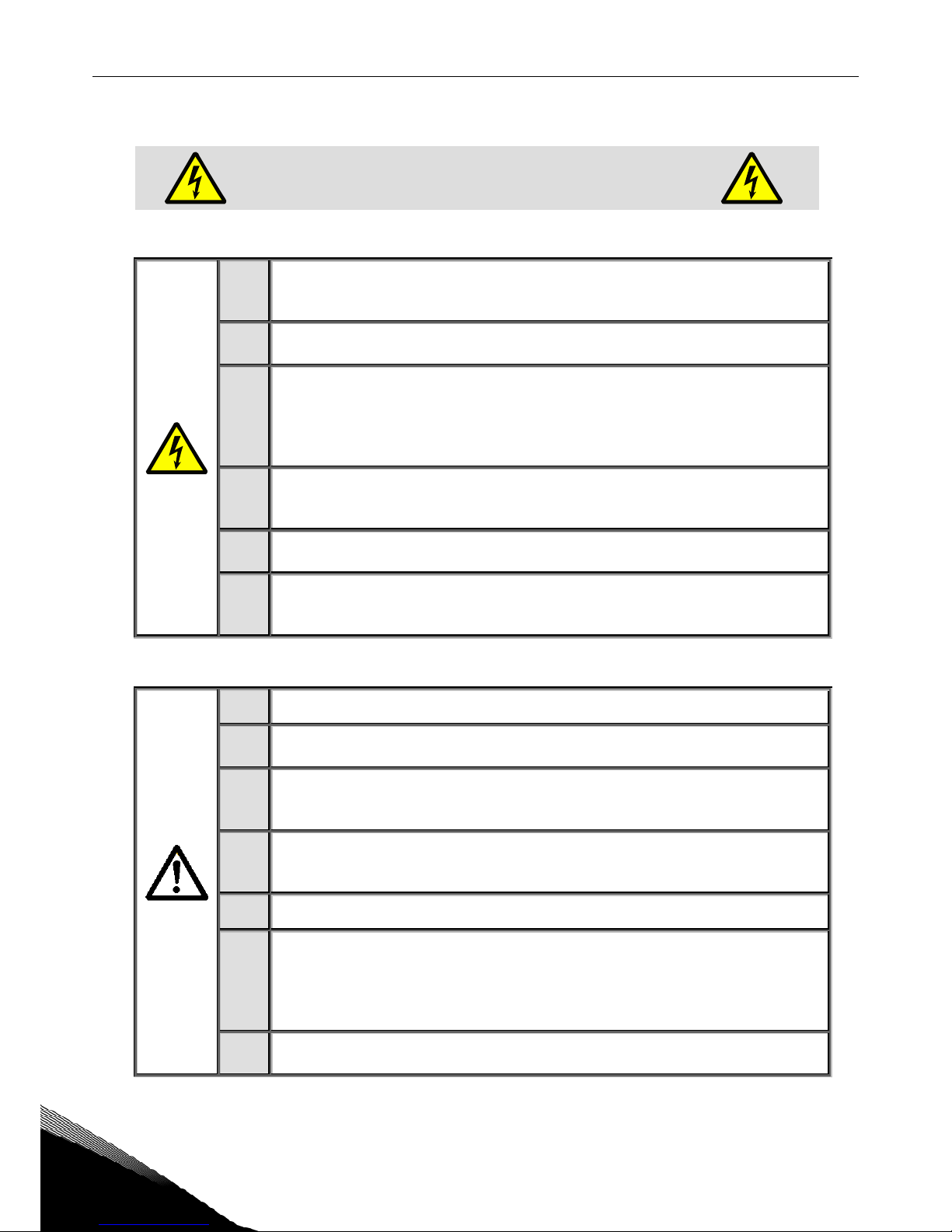
1.1 Danger
1
The components of the power unit of the frequency converter are
live
when
Vacon NX_ is connected to mains potential.
Coming into contact with this
voltage is extremely dangerous and may cause death or severe injury.
2
The motor terminals U, V, W and the DC-link/brake resistor terminals are
live
when Vacon NX_ is connected to mains,
even if the motor is not running
.
3
After disconnecting the frequency converter from the mains, wait until the fan
stops and the indicators on the keypad go out (if no keypad is attached see the
indicators on the cover). Wait 5 more minutes before doing any work on Vacon
NX_ connections. Do not even open the cover before this time has expired.
Always ensure absence of voltage before starting any electrical work!
4
The control I/O-terminals are isolated from the mains potential. However, the
relay outputs and other I/O-terminals may have a dangerous control voltage
present even when Vacon NX_ is disconnected from mains.
5
Before connecting the frequency converter to mains make sure that the
Vacon NX_ front and cable covers are closed.
6
If Vacon NX_ is disconnected from mains while running the motor, it
remains live if the motor is energized by the process. In this case the motor
functions as a generator feeding energy to the frequency converter.
1.2 Warnings
1
The Vacon NX_ frequency converter is meant for fixed installations only.
2
Do not perform any measurements when the frequency converter is connected to the mains.
3
The earth leakage current of Vacon NX_ frequency converters exceeds
3.5mA AC. According to standard EN61800-5-1, a reinforced protective
ground connection must be ensured. See chapter 1.4.
4
If the frequency converter is used as a part of a machine, the machine
manufacturer is responsible for providing the machine with a disconnecting
device (EN 60204-1).
5
Only spare parts delivered by Vacon can be used.
6
After the power-up, power brake or fault reset the motor will start immedi-
ately if the start signal is active, unless the pulse control for Start/Stop logic
has been selected. Futhermore, the I/O functionalities (including start
inputs) may change if parameters, applications or software are changed.
Disconnect, therefore, the motor if and unexpected start can cause danger.
7
Prior to measurements on the motor or the motor cable, disconnect the
motor cable from the frequency converter.
ONLY A COMPETENT ELECTRICIAN MAY CARRY OUT
THE ELECTRICAL INSTALLATION
SAFETY vacon • 9
24-hour support +358 (0)201 212 575 • Email: vacon@vacon.com
1
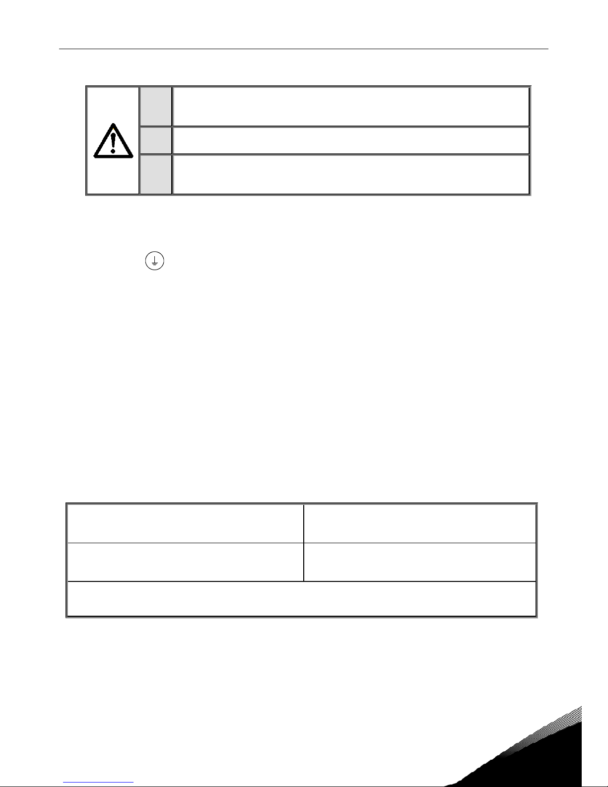
1.3 Cautions
1
Do not perform any voltage withstand tests on any part of Vacon NX_. There
is a certain procedure according to which the tests shall be performed.
Ignoring this procedure may result in damaged product.
2
Do not touch the components on the circuit boards. Static voltage discharge
may damage the components.
3
If a fault protection relay is used , it must be of at least type B, preferably B+
( according to EN 50178) , with a trip level of 300 mA. This is for fire
protection, not for touch protection in grounded systems.
1.4 Earthing and earth fault protection
The Vacon NX_ frequency converter must always be earthed with an earthing conductor connected to the
earthing terminal
.
The earth leakage current of Vacon NX_ exceeds 3.5mA AC. According to EN61800-5-1, one or more of the
following measures shall be applied, unless the touch current can be shown to be less than 3.5 mA AC or
10 mA DC:
A fixed connection and
a. The protective earthing conductor shall have a cross-sectional area of at least 10 mm
2
Cu or 16
mm
2
Al,
or
b. an automatic disconnection of the supply in case of loss of continuity of the protective earthing conductor.
See chapter 6.
or
c. provision of an additional terminal for a second protective earthing conductor of the same cross-
sectional area as the original protective earthing conductor,
Cross-sectional area of phase conductors
[mm2]
Minimum cross-sectional area of the corresponding protective earthing conductor
[mm2]
S ≤ 16
16 <
S ≤ 35
35 <
S
S
16
S/2
The values above are valid only if the protective earthing conductor is made of the same metal as the phase
conductors. If this is not so, the cross-sectional area of the protective earthing conductor shall be determined
in a manner which produces a conductance equivalent to that which results from the application of this table.
Table 1. Protective earthing conductor cross-section
The cross-sectional area of every protective earthing conductor which does not form part of the supply
cable or cable enclosure shall, in any case, be not less than:
- 2,5mm
2
if mechanical protection is provided or
- 4mm
2
if mechanical protection is not provided. For cord-connected equipment, provisions
shall be made so that the protective earthing conductor in the cord shall, in the case of
failure of the strain-relief mechanism, be the last conductor to be interrupted.
10 • vacon SAFETY
Tel. +358 (0)201 2121 • Fax +358 (0)201 212 205
1
The earth fault protection inside the frequency converter protects only the converter itself against earth
faults in the motor or the motor cable. It is not intended for personal safety.
Due to the high capacitive currents present in the frequency converter, fault current protective switches
may not function properly.
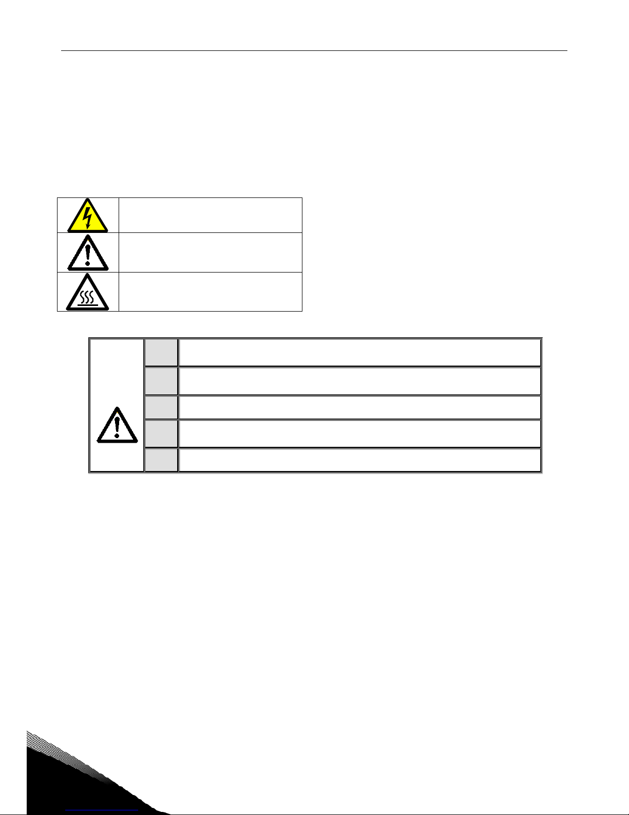
1.5 Running the motor
Warning symbols
For your own safety, please pay special attention to the instructions marked with the following symbols:
=
Dangerous voltage
=
General warning
=
Hot surface – Risk of burn
MOTOR RUN CHECK LIST
1
Before starting the motor, check that the motor is mounted properly and
ensure that the machine connected to the motor allows the motor to be started.
2
Set the maximum motor speed (frequency) according to the motor and the
machine connected to it.
3
Before reversing the motor make sure that this can be done safely.
4
Make sure that no power correction capacitors are connected to the motor
cable.
5
Make sure that the motor terminals are not connected to mains potential.

EU DIRECTIVE vacon • 11
24-hour support +358 (0)201 212 575 • Email: vacon@vacon.com
2
2. EU DIRECTIVE
2.1 CE marking
The CE marking on the product guarantees the free movement of the product within the EEA (European
Economic Area).
Vacon NX_ frequency converters carry the CE label as a proof of compliance with the Low Voltage Directive
(LVD) and the Electro Magnetic Compatibility (EMC). The company SGS FIMKO has acted as the Competent
Body.
2.2 EMC directive
2.2.1
General
The EMC Directive provides that the electrical apparatus must not excessively disturb the environment it is
used in, and, on the other hand, it shall have an adequate level of immunity toward other disturbances from
the same environment.
The compliance of Vacon NX_ frequency converters with the EMC directive is verified with Technical Construction Files (TCF) checked and approved by SGS FIMKO, which is a Competent Body. The Technical
Construction Files are used to authenticate the comformity of Vacon frequency converters with the Directive because such a large-sized product family is impossible to be tested in a laboratory environment and
because the combinations of installation vary greatly.
2.2.2
Technical criteria
Our basic idea was to develop a range of frequency converters offering the best possible usability and costefficiency. EMC compliance was a major consideration from the outset of the design.
Vacon NX_ frequency converters are marketed throughout the world, a fact which makes the EMC requirements of customers different. As far as the immunity is concerned, all Vacon NX_ frequency converters are
designed to fulfil even the strictest requirements, while as regards the emission level, the customer may
want to upgrade Vacon's already high ability to filter electro-magnetic disturbances.
2.2.3
Vacon frequency converter EMC classification
Vacon NX_ frequency converters are divided into five classes according to the level of electromagnetic
disturbances emitted, the requirements of a power system network and the installation environment (see
chapter 2.2.3.1). The EMC class of each product is defined in the type designation code.
Vacon EMC class C1 (NX_5, FR4 to FR6, Protection class IP54):
Frequency converters of this class comply with the requirements of category C1 of the product standard
EN 61800-3 (2004). Category C1 ensures the best EMC characteristics and it includes converters the rated
voltage of which is less than 1000V and which are intended for use in the 1st environment. NOTE: If the
protection class of the frequency converter is IP21 the requirements of class C1 are fulfilled only as far as
the conducted emissions are concerned.
Vacon EMC class C2 (NX_5, FR4 to FR9 and NX_2, FR4 to FR9):
Frequency converters of this class comply with the requirements of category C2 of the product standard
EN 61800-3 (2004). Category C2 includes converters in fixed installations and the rated voltage of which is
less than 1000V. The class C2 frequency converters can be used both in the 1st and the 2nd environment.

12 • vacon EU DIRECTIVE
Tel. +358 (0)201 2121 • Fax +358 (0)201 212 205
2
Vacon EMC class L (Protection classes IP21 and IP54: NX_5 FR10 and greater, NX_6 FR6 and greater):
Frequency converters of this class comply with the requirements of category C3 of the product standard
EN 61800-3 (2004). Category C3 includes converters the rated voltage of which is less than 1000V and
which are intended for use in the second environment only.
Vacon EMC class T:
Frequency converters of this class fulfil the product standard EN 61800-3 (2004) if intended to be used in IT
systems. In IT systems, the networks are isolated from earth, or connected to earth through high
impedance to achieve a low leakage current. NOTE: if converters are used with other supplies, no EMC
requirements are complied with.
Vacon EMC class N:
The drives of this class do not provide EMC emission protection. These kinds of drives are mounted in
enclosures. NOTE: An external EMC filter is usually required to fulfil the EMC emission requirements.
All Vacon NX_ frequency converters fulfil all EMC immunity requirements (standard EN 61800-3
(2004).
Note: For changing the EMC protection class of your Vacon NX_ frequency converter from class H or L to
class T, please refer to the instructions given in Chapter 6.1.3.
2.2.3.1 Environment definitions in product standard EN 61800-3 (2004)
First environment: Environment that includes domestic premises. It also includes establishments directly
connected without intermediate transformers to a low-voltage power supply network which supplies
buildings used for domestic purposes.
NOTE: houses, apartments, commercial premises or offices in a residential building are examples of first
environment locations.
Second environment: Environment that includes all establishments other than those directly connected to
a low-voltage power supply network which supplies buildings used for domestic purposes.
NOTE: industrial areas, technical areas of any building fed from a dedicated transformer are examples of
second environment locations.
2.2.4
Manufacturer's declaration of conformity
The following pages present the Manufacturer's Declarations of Conformity assuring the compliance of
Vacon frequency converters with the EMC-directives.
Warning:
In a domestic environment this product may cause radio interference in which case the
user may be required to take adequate measures.
EU DIRECTIVE vacon • 13
24-hour support +358 (0)201 212 575 • Email: vacon@vacon.com
2
EU DECLARATION OF CONFORMITY
We
Manufacturer's name:
Vacon Oyj
Manufacturer's address: P.O.Box 25
Runsorintie 7
FIN-65381 Vaasa
Finland
hereby declare that the product
Product name: Vacon NXS/P Frequency converter
Model designation: Vacon NXS/P 0003 2…. to 0300 2….
has been designed and manufactured in accordance with the following
standards:
Safety: EN 60204 -1 (2009) (as relevant)
EN 61800-5-1 (2007)
EMC: EN61800-3 (2004)
and conforms to the relevant safety provisions of the Low Voltage Directive
(2006/95/EC) and EMC Directive 2004/108/EC.
It is ensured through internal measures and quality control that the product
conforms at all times to the requirements of the current Directive and the
relevant standards.
In Vaasa, 31st of August, 2010
Vesa Laisi
President
The year the CE marking was affixed: 2003
14 • vacon EU DIRECTIVE
Tel. +358 (0)201 2121 • Fax +358 (0)201 212 205
2
EU DECLARATION OF CONFORMITY
We
Manufacturer's name: Vacon Oyj
Manufacturer's address:
P.O.Box 25
Runsorintie 7
FIN-65381 Vaasa
Finland
hereby declare that the product
Product name:
Vacon NXS/P Frequency converter
Model designation: Vacon NXS/P 0003 5…. to 1030 5….
has been designed and manufactured in accordance with the following
standards:
Safety: EN 60204 -1 (2009) (as relevant)
EN 61800-5-1 (2007)
EMC: EN61800-3 (2004)
and conforms to the relevant safety provisions of the Low Voltage Directive
(2006/95/EC) and EMC Directive 2004/108/EC
.
It is ensured through internal measures and quality control that the product
conforms at all times to the requirements of the current Directive and the
relevant standards.
In Vaasa, 31st of August, 2010
Vesa Laisi
President
The year the CE marking was affixed: 2002

vacon • 15
24-hour support +358 (0)201 212 575 • Email: vacon@vacon.com
2
EU DECLARATION OF CONFORMITY
We
Manufacturer's name:
Vacon Oyj
Manufacturer's address: P.O.Box 25
Runsorintie 7
FIN-65381 Vaasa
Finland
hereby declare that the product
Product name: Vacon NXS/P Frequency converter
Model designation: Vacon NXS/P 0004 6…. to 0820 6….
has been designed and manufactured in accordance with the following
standards:
Safety: EN 60204 -1 (2009) (as relevant)
EN 61800-5-1 (2007)
EMC: EN61800-3 (2004)
and conforms to the relevant safety provisions of the Low Voltage Directive
(2006/95/EC) and EMC Directive 2004/108/EC.
It is ensured through internal measures and quality control that the product
conforms at all times to the requirements of the current Directive and the
relevant standards.
In Vaasa, 31st of August, 2010
Vesa Laisi
President
The year the CE marking was affixed: 2003
16 • vacon RECEIPT OF DELIVERY
Tel. +358 (0)201 2121 • Fax +358 (0)201 212 205
3
3. RECEIPT OF DELIVERY
Vacon NX_ frequency converters have undergone scrupulous tests and quality checks at the factory before
they are delivered to the customer. However, after unpacking the product, check that no signs of transport
damages are to be found on the product and that the delivery is complete (compare the type designation of
the product to the code below,(Figure 3-1).
Should the drive have been damaged during the shipping, please contact primarily the cargo insurance
company or the carrier.
If the delivery does not correspond to your order, contact the supplier immediately.
In the small plastic bag included in the delivery you will find a silver
Drive modified
sticker. The purpose of
the sticker is to notify the service personnel about the modifications made in the frequency converter.
Attach the sticker on the side of the frequency converter to avoid losing it. Should the frequency converter
be later modified (option board added, IP or EMC protection level changed), mark the change in the sticker.
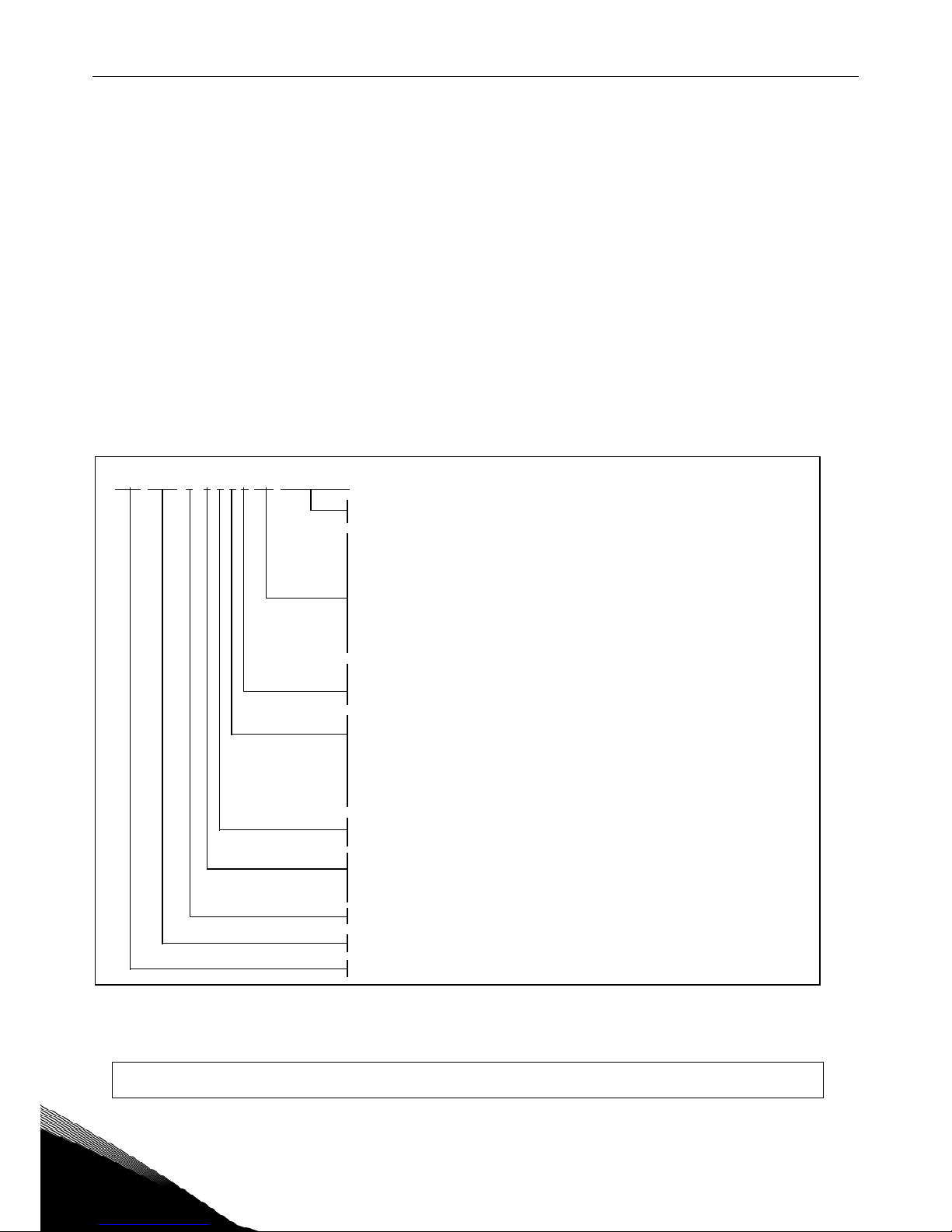
3.1 Type designation code
Figure 3-1. Vacon NX_ type designation code
Note:
Ask your nearest Vacon representative office for other possible installation combinations.
NXS 000 0
A 2 H 1 SS V A 1A2000 0C3
5
nk3_1.fh11
Product range: NXS = standard, NXP = high-performance
Nominal current (low overlo ad)
0007 = 7 A, 0022 = 22 A, 0205 = 205 A etc.
Nominal mains voltage (3-phase):
2 = 208–240Vac, 5 = 380–500Vac, 6 = 525–690Vac (All 3-phase)
Control keypad:
A = standard (alpha-numeric)
B = no local control keypad
F = dummy keypad
G = graphic display
Enclosure class:
0 = IP00 (FR9 only), 2 = IP21/NEMA 1, 5 = IP54 (NEMA 12)
EMC emission level:
C = fulfils requir
ements of c
ategory C1 of sta ndard EN61800-3 (2004),
1st environment and rated voltage less than 1000V
H = fulfils requirements of category C2 of standard EN61800-3 (2004),
fixed installations and rated voltage le ss than 1000V
L = fulf ils requirements of category C3 of standard EN61800-3 (2004),
2nd environment and rated voltage less than 1000V
T = fulfils standard EN61800-3 (2004) when used in IT networks
N = No EMC emission protection. An external EMC filter needed
Brake chopper
0 = no brake chopper
1 = internal brake chopper
2 = internal brake chopper and resistor
Option boar
ds; each sl
ot is represented by two characters whe re:
A = basic I/O boar
d, B = expander I/O boar
d,
C = fieldbus board, D = special board
Hardware modifications; Supply - Mounting - Boards
Sxx = 6-pulse connection (FR4 to FR14)
Bxx = Additional DC-connection (FR8...FR12)
Jxx = FR10...11 stand-alone wit h main switch and DC-link t
erminals
xSx = Air-coole d drive
xxS = Standard boards (FR4 to FR 8)
xxV = Varnished boards (FR4 to FR8)
xxF = Standard boa rds (FR9 to FR14)
xxG = V
arnished boards (FR9 to FR14)
xxA = Standard bo ards (FR10 to FR12 standalone drives)
xxB = Var nished boards (FR10 to FR 12 standalone drives)

RECEIPT OF DELIVERY vacon • 17
24-hour support +358 (0)201 212 575 • Email: vacon@vacon.com
3
3.2 Storage
If the frequency converter is to be kept in store before use make sure that the ambient conditions are
acceptable:
Storing temperature –40…+70
°C
Relative humidity <95%, no condensation
If the converter is to be stored during longer periods power should be connected to the converter once a
year and kept on for at least 2 hours. If the storage time exceeds 12 months the electrolytic DC capacitors
need to be charged with caution. Therefore, such a long storage time is not recommended. If longer
storage time is, however, necessary, follow the instructions in chapter 3.3.1 to recharge the capacitors.
3.3 Maintenance
In normal conditions, Vacon NX_ frequency converters are maintenance-free. However, regular
maintenance is recommended to ensure a trouble-free operation and a long lifetime of the drive. We
recommend to follow the table below for maintenance intervals.
Maintenance interval Maintenance action
Whenever necessary
•
Clean heatsink
Regularly
•
Check tightening torques of terminals
12 months (if unit stored)
• Recharge capacitors (see chapter 3.3.1)
6-24 months
(depending on environment)
• Check input and output terminals and control
I/O terminals.
• Clean cooling tunnel.
• Check operation of cooling fan, check for cor-
rosion on terminals, busbars and other surfaces
•
Check door filters in case of cabinet installation
5-7 years
• Change cooling fans:
- main fan
- internal IP54 fan
-
cabinet cooling fan/filter
5-10 years
•
Change DC bus capacitors
Table 3-1. Maintenance intervals
3.3.1
Capacitor recharge
After a longer storage time the capacitors need to be recharged in order to avoid capacitor damage.
Possible high leakage current through the capacitors must be limited. The best way to achieve this is to
use a DC-power supply with adjustable current limit.
1) Set the current limit to 300…800mA according to the size of the drive.
2) Then connect the DC-power supply to the B+/B- terminals (DC+ to B+, DC- to B-) of the DC-link or
directly to the capacitor terminals. NX converters with no B+/B- terminals (FR8/FR9) can be powered
connecting the DC-supply between two input phases (L1 and L2).
3) In drives FR8 to FR12: To ensure full recharge of capacitors, remove the fuses of the cooling fan. Ask
factory for further instructions if necessary.
4) Then set the DC-voltage to the nominal DC-voltage level of the unit (1.35*Un AC) and supply the
converter for at least 1h.
If DC-voltage is not available and the unit has been stored much longer than 12 months deenergized,
consult the factory before connecting power.

18 • vacon RECEIPT OF DELIVERY
Tel. +358 (0)201 2121 • Fax +358 (0)201 212 205
3
3.4 Warranty
Only manufacturing defects are covered by the warranty. The manufacturer assumes no responsibility for
damages caused during or resulting from transport, receipt of the delivery, installation, commissioning or
use.
The manufacturer shall in no event and under no circumstances be held responsible for damages and
failures resulting from misuse, wrong installation, unacceptable ambient temperature, dust, corrosive
substances or operation outside the rated specifications.
Neither can the manufacturer be held responsible for consequential damages.
The Manufacturer's time of warranty is 18 months from the delivery or 12 months from the commissioning
whichever expires first (Vacon Warranty Terms).
The local distributor may grant a warranty time different from the above. This warranty time shall be
specified in the distributor's sales and warranty terms. Vacon assumes no responsibility for any other
warranties than that granted by Vacon itself.
In all matters concerning the warranty, please contact first your distributor.
TECHNICAL DATA vacon • 19
24-hour support +358 (0)201 212 575 • Email: vacon@vacon.com
4
4. TECHNICAL DATA
4.1 Introduction
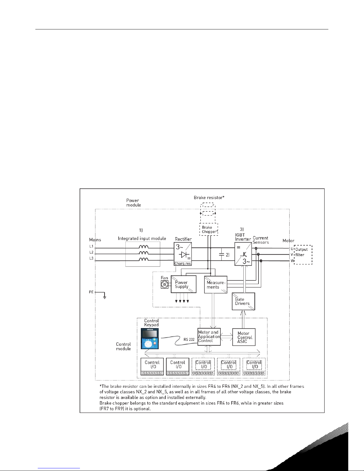
Figure 4-1 presents the block diagram of the Vacon NX_ frequency converter. The frequency converter
mechanically consists of two units, the Power Unit and the Control Unit. Pictures of the mechanical
assemblage on pages 57 to 65.
The three-phase AC-choke (1) at the mains end together with the DC-link capacitor (2) form an LC-filter,
which, again, together with the diode bridge produce the DC-voltage supply to the IGBT Inverter Bridge (3)
block. The AC-choke also functions as a filter against High Frequency disturbances from the mains as well
as against those caused by the frequency converter to the mains. It, in addition, enhances the waveform of
the input current to the frequency converter. The entire power drawn by the frequency converter from the
mains is active power.
The IGBT Inverter Bridge produces a symmetrical, 3-phase PWM-modulated AC-voltage to the motor.
The Motor and Application Control Block is based on microprocessor software. The microprocessor
controls the motor basing on the information it receives through measurements, parameter settings,
control I/O and control keypad. The motor and application control block controls the motor control ASIC
which, in turn, calculates the IGBT positions. Gate drivers amplify these signals for driving the IGBT
inverter bridge.
Figure 4-1 Vacon NX_ block diagram

20 • vacon TECHNICAL DATA
Tel. +358 (0)201 2121 • Fax +358 (0)201 212 205
4
The control keypad constitutes a link between the user and the frequency converter. The control keypad is
used for parameter setting, reading status data and giving control commands. It is detachable and can be
operated externally and connected via a cable to the frequency converter. Instead of the control keypad,
also a PC can be used to control the frequency converter if connected through a similar cable.
You can have your frequency converter equipped with a control I/O board which is either isolated (OPTA8)
or not isolated (OPTA1) from the ground.
The basic control interface and the parameters (the Basic Application) are easy to use. If a more versatile
interface or parameters are required, a more suitable application can be chosen from the "All in One+"
Application Package. See the "All in One+" Application Manual for more information on the different
applications.
A brake resistor is available as internal option for frames FR4 to FR6 of voltage classes NX_2 and NX_5. In
all other frames of voltage classes NX_2 and NX_5, as well as in all frames of all other voltage classes, the
brake resistor is available as option and installed externally.
Optional I/O expander boards that increase the number of inputs and outputs to be used are also available.
For closer information, contact the Manufacturer or your local distributor (see back cover).
TECHNICAL DATA vacon • 21
24-hour support +358 (0)201 212 575 • Email: vacon@vacon.com
4
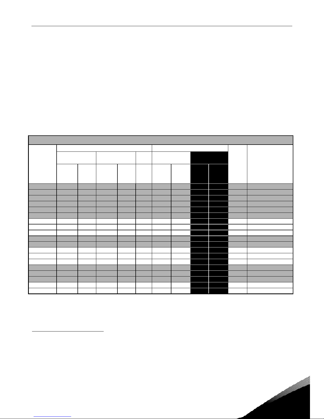
4.2 Power ratings
4.2.1
Vacon NX_2 – Mains voltage 208—240 V
High overload = Max current IS, 2 sec/20 sec, 150% overloadability, 1 min/10 min
Following continuous operation at rated output current, 150 % rated output current (IH)
for 1 min, followed by a period of load current less than rated current, and of such
duration that the r.m.s output current, over the duty cycle, does not exceed rated
output current (IH)
Low overload = Max current IS, 2 sec/20 sec, 110% overloadability, 1 min/10 min
Following continuous operation at rated output current, 110% rated output current (IL)
for 1 min, followed by a period of load current less than rated current, and of such
duration that the r.m.s output current, over the duty cycle, does not exceed rated
output current (IL)
All sizes are available as IP21/NEMA1 or IP54/NEMA12.
Mains voltage 208-240 V, 50/60 Hz, 3~
Frequency
converter
type
Loadability
Motor shaft power
Frame
Dimensions and
weight
WxHxD/kg
Low High 230V supply 208-240V
supply
Rated
continuous
current I
L
(A)
10%
overload
current
(A)
Rated
continuous
current I
H
(A)
50%
overload
current
(A)
Max
current
I
S
10%
overload
40°C
P(kW)
50%
overload
50°C
P(kW)
10%
overload
40°C
P(hp)
50%
overload
50°C
P(hp)
NX_ 0003 2* 3.7 4.1 2.4 3.6 4.8 0.55 0.37 0.75 FR4 128x292x190/5
NX_ 0004 2 4.8 5.3 3.7 5.6 7.4 0.75 0.55 1 0.75 FR4 128x292x190/5
NX_ 0007 2 6.6 7.3 4.8 7.2 9.6 1.1 0.75 1.5 1 FR4 128x292x190/5
NX_ 0008 2 7.8 8.6 6.6 9.9 13.2 1.5 1.1 2 1.5 FR4 128x292x190/5
NX_ 0011 2 11 12.1 7.8 11.7 15.6 2.2 1.5 3 2 FR4 128x292x190/5
NX_ 0012 2 12.5 13.8 11 16.5 22 3 2.2 - 3 FR4 128x292x190/5
NX_ 0017 2 17.5 19.3 12.5 18.8 25 4 3 5 - FR5 144x391x214/8,1
NX_ 0025 2 25 27.5 17.5 26.3 35 5.5 4 7.5 5 FR5 144x391x214/8,1
NX_ 0031 2 31 34.1 25 37.5 50 7.5 5.5 10 7.5 FR5 144x391x214/8,1
NX_ 0048 2 48 52.8 31 46.5 62 11 7.5 15 10 FR6 195x519x237/18,5
NX_ 0061 2
61
67.1
48
72.0
96
15
11
20
15
FR6
195x519x237/18,5
NX_ 0075 2 75 83 61 92 122 22 15 25 20 FR7 237x591x257/35
NX_ 0088 2 88 97 75 113 150 22 22 30 25 FR7 237x591x257/35
NX_ 0114 2 114 125 88 132 176 30 22 40 30 FR7 237x591x257/35
NX_ 0140 2 140 154 105 158 210 37 30 50 40 FR8 291x758x344/58
NX_ 0170 2 170 187 140 210 280 45 37 60 50 FR8 291x758x344/58
NX_ 0205 2
205
226
170
255
336
55
45
75
60
FR8
291x758x344/58
NX_ 0261 2 261 287 205 308 349 75 55 100 75 FR9 480x1150x362/146
NX_ 0300 2 300 330 245 368 444 90 75 125 100 FR9 480x1150x362/146
Table 4-1. Power ratings and dimensions of Vacon NX_, supply voltage 208—240V.
Note: The rated currents in given ambient temperatures are achieved only when the switching frequency is
equal to or less than the factory default.
*
Only available for NXP range.
22 • vacon TECHNICAL DATA
Tel. +358 (0)201 2121 • Fax +358 (0)201 212 205
4
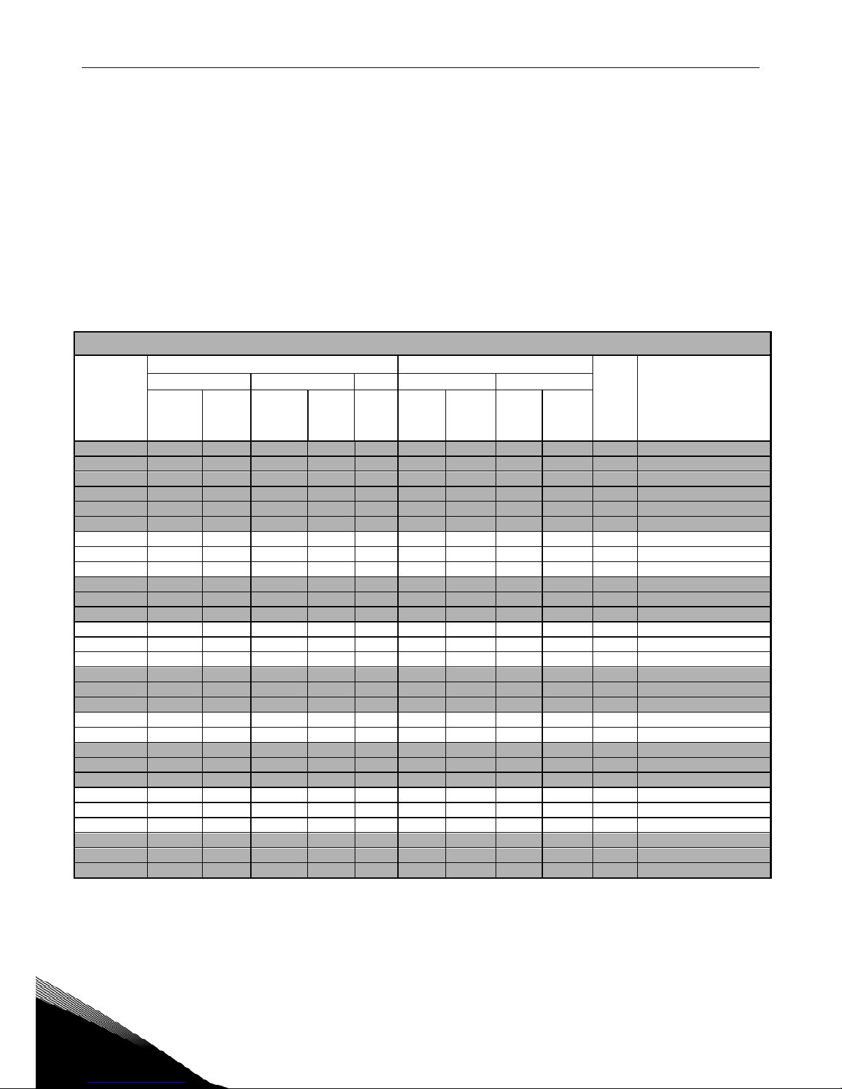
4.2.2
Vacon NX_5 – Mains voltage 380—500 V
High overload = Max current IS, 2 sec/20 sec, 150% overloadability, 1 min/10 min
Following continuous operation at rated output current, 150 % rated output current (IH)
for 1 min, followed by a period of load current less than rated current, and of such
duration that the r.m.s output current, over the duty cycle, does not exceed rated
output current (IH)
Low overload = Max current IS, 2 sec/20 sec, 110% overloadability, 1 min/10 min
Following continuous operation at rated output current, 110% rated output current (IL)
for 1 min, followed by a period of load current less than rated current, and of such
duration that the r.m.s output current, over the duty cycle, does not exceed rated
output current (IL)
All sizes are available as IP21/NEMA1 Sizes FR4 to FR10 are additionally available as IP54/NEMA12.
FR12 is available only as NXP.
Mains voltage 380-500 V, 50/60 Hz, 3~
Frequency
converter
type
Loadability
Motor shaft power
Frame
Dimensions and
weight
WxHxD/kg
Low High 380V supply 500V supply
Rated
continuous
current I
L
(A)
10%
overload
current
(A)
Rated
continuous
current IH
(A)
50%
overload
current
(A)
Max
current
IS
10%
overload
40°C
P(kW)
50%
overload
50°C
P(kW)
10%
overload
40°C
P(kW)
50%
overload
50°C
P(kW)
NX_ 0003 5 3.3 3.6 2.2 3.3 4.4 1.1 0.75 1.5 1.1 FR4 128x292x190/5
NX_ 0004 5 4.3 4.7 3.3 5.0 6.2 1.5 1.1 2.2 1.5 FR4 128x292x190/5
NX_ 0005 5
5.6
6.2
4.3
6.5
8.6
2.2
1.5 3 2.2
FR4
128x292x190/5
NX_ 0007 5 7.6 8.4 5.6 8.4 10.8 3 2.2 4 3 FR4 128x292x190/5
NX_ 0009 5 9 9.9 7.6 11.4 14 4 3 5.5 4 FR4 128x292x190/5
NX_ 0012 5 12 13.2 9 13.5 18 5.5 4 7.5 5.5 FR4 128x292x190/5
NX_ 0016 5 16 17.6 12 18.0 24 7.5 5.5 11 7.5 FR5 144x391x214/8.1
NX_ 0022 5 23 25.3 16 24.0 32 11 7.5 15 11 FR5 144x391x214/8.1
NX_ 0031 5 31 34 23 35 46 15 11 18.5 15 FR5 144x391x214/8.1
NX_ 0038 5 38 42 31 47 62 18.5 15 22 18.5 FR6 195x519x237/18.5
NX_ 0045 5 46 51 38 57 76 22 18.5 30 22 FR6 195x519x237/18.5
NX_ 0061 5 61 67 46 69 92 30 22 37 30 FR6 195x519x237/18.5
NX_ 0072 5 72 79 61 92 122 37 30 45 37 FR7 237x591x257/35
NX_ 0087 5 87 96 72 108 144 45 37 55 45 FR7 237x591x257/35
NX_ 0105 5 105 116 87 131 174 55 45 75 55 FR7 237x591x257/35
NX_ 0140 5 140 154 105 158 210 75 55 90 75 FR8 291x758x344/58
NX_ 0168 5
170
187
140
210
280
90
75
110
90
FR8
291x758x344/58
NX_ 0205 5 205 226 170 255 336 110 90 132 110 FR8 291x758x344/58
NX_ 0261 5 261 287 205 308 349 132 110 160 132 FR9 480x1150x362/146
NX_ 0300 5
300
330
245
368
444
160
132
200
160
FR9
480x1150x362/146
NX_ 0385 5 385 424 300 450 540 200 160 250 200 FR10 595x2018x602/340
NX_ 0460 5 460 506 385 578 693 250 200 315 250 FR10 595x2018x602/340
NX_ 0520 5 520 572 460 690 828 250 250 355 315 FR10 595x2018x602/340
NX_ 0590 5 590 649 520 780 936 315 250 400 355 FR11 794x2018x602/470
NX_ 0650 5 650 715 590 885 1062 355 315 450 400 FR11 794x2018x602/470
NX_ 0730 5 730 803 650 975 1170 400 355 500 450 FR11 794x2018x602/470
NXP 0820 5 820 902 730 1095 1314 450 400 500 500 FR12 1210x2017x602/600
NXP 0920 5 920 1012 820 1230 1476 500 450 630 500 FR12 1210x2017x602/600
NXP 1030 5 1030 1133 920 1380 1656 500 500 710 630 FR12 1210x2017x602/600
Table 4-2. Power ratings and dimensions of Vacon NX_, supply voltage 380—500V.
Note: The rated currents in given ambient temperatures are achieved only when the switching frequency is equal to
or less than the factory default.
Note: The rated currents for FR10 to FR12 are valid at an ambient temperature of 40°C (except for 0520 5: rated
currents valid at an ambient temperature of 35°C).
TECHNICAL DATA vacon • 23
24-hour support +358 (0)201 212 575 • Email: vacon@vacon.com
4
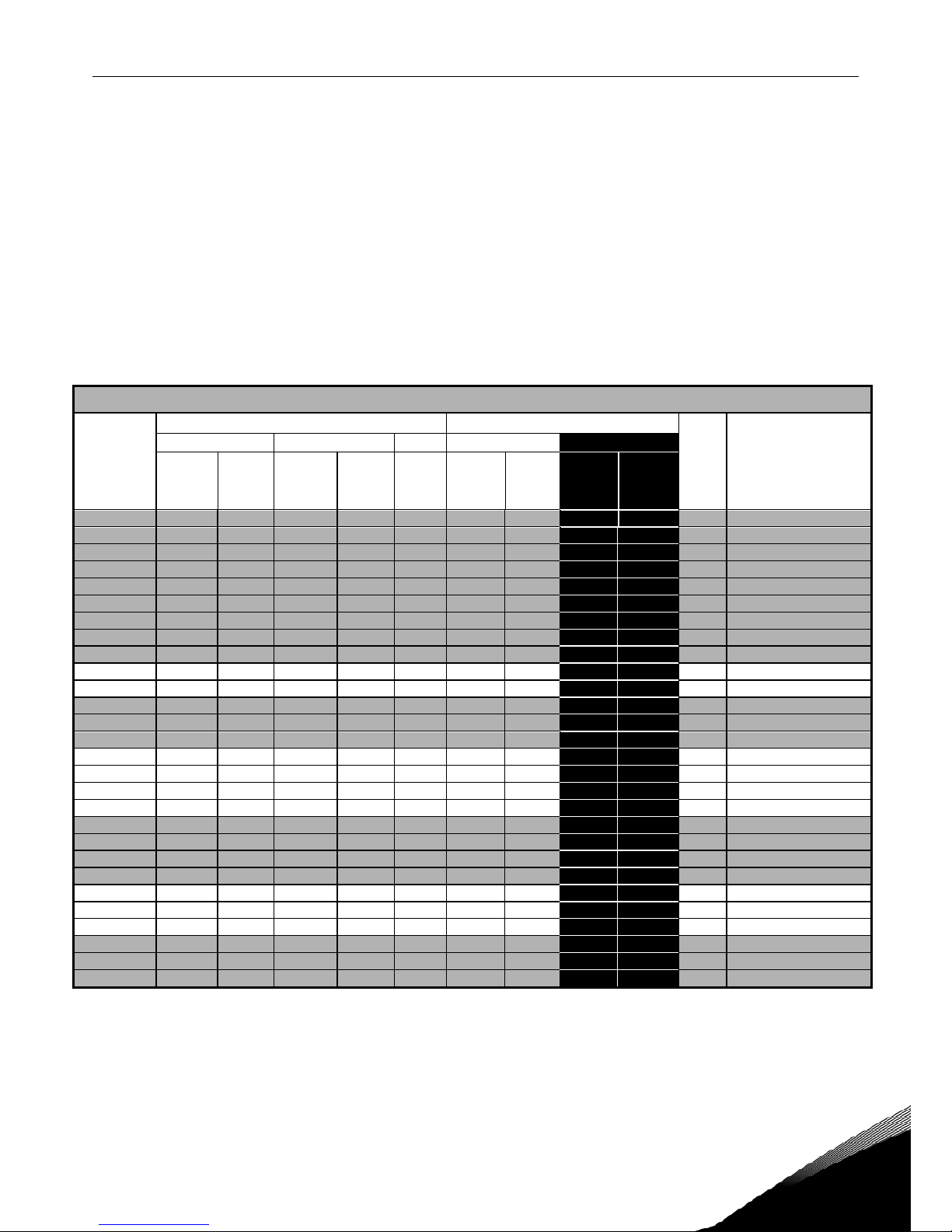
4.2.3
Vacon NX_6 – Mains voltage 525—690 V
High overload = Max current IS, 2 sec/20 sec, 150% overloadability, 1 min/10 min
Following continuous operation at rated output current, 150 % rated output current (IH)
for 1 min, followed by a period of load current less than rated current, and of such
duration that the r.m.s output current, over the duty cycle, does not exceed rated
output current (IH)
Low overload = Max current IS, 2 sec/20 sec, 110% overloadability, 1 min/10 min
Following continuous operation at rated output current, 110% rated output current (IL)
for 1 min, followed by a period of load current less than rated current, and of such
duration that the r.m.s output current, over the duty cycle, does not exceed rated
output current (IL)
All sizes are available as IP21/NEMA1 Sizes FR4 to FR10 are additionally available as IP54/NEMA12.
FR12 is available only as NXP.
Mains voltage 525-690 V, 50/60 Hz, 3~
Frequency
converter
type
Loadability
Motor shaft power
Frame
Dimensions and
weight
WxHxD/kg
Low High 690V supply 575V supply
Rated
continuous
current I
L
(A)
10%
overload
current
(A)
Rated
continuous
current IH
(A)
50%
overload
current
(A)
Max
current
IS
10%
overload
40°C
P(kW)
50%
overload
50°C
P(kW)
10%
overload
40°C
P(hp)
50%
overload
50°C
P(hp)
NX_ 0004 6
4.5
5.0
3.2
4.8
6.4 3 2.2
3.0
2.0
FR6
195x519x237/18,5
NX_ 0005 6 5.5 6.1 4.5 6.8 9.0 4 3 3.0 3.0 FR6 195x519x237/18,5
NX_ 0007 6 7.5 8.3 5.5 8.3 11.0 5.5 4 5.0 3.0 FR6 195x519x237/18,5
NX_ 0010 6 10 11.0 7.5 11.3 15.0 7.5 5.5 7.5 5.0 FR6 195x519x237/18,5
NX_ 0013 6 13.5 14.9 10 15.0 20.0 11 7.5 10 7.5 FR6 195x519x237/18,5
NX_ 0018 6 18 19.8 13.5 20.3 27 15 11 15 10 FR6 195x519x237/18,5
NX_ 0022 6 22 24.2 18 27.0 36 18.5 15 20 15 FR6 195x519x237/18,5
NX_ 0027 6 27 29.7 22 33.0 44 22 18.5 25 20 FR6 195x519x237/18,5
NX_ 0034 6 34 37 27 41 54 30 22 30 25 FR6 195x519x237/18,5
NX_ 0041 6 41 45 34 51 68 37.5 30 40 30 FR7 237x591x257/35
NX_ 0052 6 52 57 41 62 82 45 37.5 50 40 FR7 237x591x257/35
NX_ 0062 6
62
68
52
78
104
55
45
60
50
FR8
291x758x344/58
NX_ 0080 6 80 88 62 93 124 75 55 75 60 FR8 291x758x344/58
NX_ 0100 6 100 110 80 120 160 90 75 100 75 FR8 291x758x344/58
NX_ 0125 6 125 138 100 150 200 110 90 125 100 FR9 480x1150x362/146
NX_ 0144 6 144 158 125 188 213 132 110 150 125 FR9 480x1150x362/146
NX_ 0170 6 170 187 144 216 245 160 132 150 150 FR9 480x1150x362/146
NX_ 0208 6
208
229
170
255
289
200
160
200
150
FR9
480x1150x362/146
NX_ 0261 6 261 287 208 312 375 250 200 250 200 FR10 595x2018x602/340
NX_ 0325 6 325 358 261 392 470 315 250 300 250 FR10 595x2018x602/340
NX_ 0385 6 385 424 325 488 585 355 315 400 300 FR10 595x2018x602/340
NX_ 0416 6 416 458 325 488 585 400 315 450 300 FR10 595x2018x602/340
NX_ 0460 6 460 506 385 578 693 450 355 450 400 FR11 794x2018x602/400
NX_ 0502 6 502 552 460 690 828 500 450 500 450 FR11 794x2018x602/400
NX_ 0590 6 590 649 502 753 904 560 500 600 500 FR11 794x2018x602/470
NXP 0650 6 650 715 590 885 1062 630 560 650 600 FR12 1210x2017x602/600
NXP 0750 6 750 825 650 975 1170 710 630 800 650 FR12 1210x2017x602/600
NXP 0820 6 820 902 650 975 1170 800 630 800 650 FR12 1210x2017x602/600
Table 4-3. Power ratings and dimensions of Vacon NX_, supply voltage 525—690V.
Note: The rated currents in given ambient temperatures are achieved only when the switching frequency is equal to
or less than the factory default.
Note: The rated currents for FR10 to FR12 are valid at an ambient temperature of 40°C (except for 0416 6, 0590 6 and
0820 6: rated currents valid at an ambient temperature of 35°C).
24 • vacon TECHNICAL DATA
Tel. +358 (0)201 2121 • Fax +358 (0)201 212 205
4
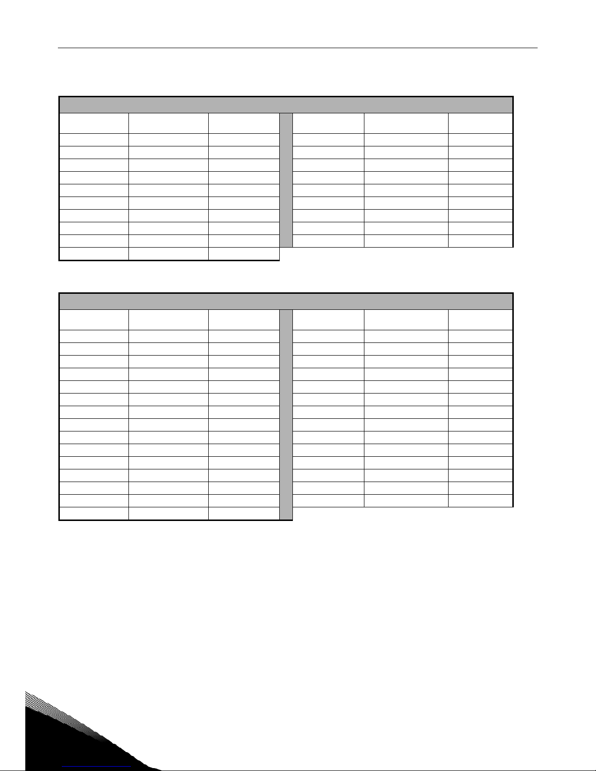
4.2.4
Brake resistor ratings
Mains voltage 208-240 V, 50/60 Hz, 3~
Converter type
Max. brake current
[I]
Resistor nom
[ohm]
Converter type
Max. brake current
[I]
Resistor nom.
[ohm]
NX_ 0003 2 15 30
NX_ 0061 2 46 10
NX_ 0004 2 15 30
NX_ 0075 2 148 3.3
NX_ 0007 2 15 30
NX_ 0088 2 148 3.3
NX_ 0008 2 15 30
NX_ 0114 2 148 3.3
NX_ 0011 2 15 30
NX_ 0140 2 296 1.4
NX_ 0012 2 15 30
NX_ 0170 2 296 1.4
NX_ 0017 2 15 30
NX_ 0205 2 296 1.4
NX_ 0025 2 15 30
NX_ 0261 2 296 1.4
NX_ 0031 2 23 20
NX_ 0300 2 296 1.4
NX_ 0048 2 46 10
Table 4-4. Brake resistor ratings, Vacon NX_, supply voltage 208–240V
Mains voltage 380-500 V, 50/60 Hz, 3~
Converter type
Max. brake current
[I]
Resistor nom
[ohm]
Converter type
Max. brake current
[I]
Resistor nom.
[ohm]
NX_ 0003 5 12 63
NX_ 0140 5 222 3.3
NX_ 0004 5 12 63
NX_ 0168 5 222 3.3
NX_ 0005 5 12 63
NX_ 0205 5 222 3.3
NX_ 0007 5 12 63
NX_ 0261 5 222 3.3
NX_ 0009 5 12 63
NX_ 0300 5 222 3.3
NX_ 0012 5 12 63
NX_ 0385 5 570 1,4
NX_ 0016 5 12 63
NX_ 0460 5 570 1,4
NX_ 0022 5 12 63
NX_ 0520 5 570 1,4
NX_ 0031 5 17 42
NX_ 0590 5 855 0,9
NX_ 0038 5 35 21
NX_ 0650 5 855 0,9
NX_ 0045 5 35 21
NX_ 0730 5 855 0,9
NX_ 0061 5 51 14
NX_ 0820 5 2 x 570 2 x 1,4
NX_ 0072 5 111 6.5
NX_ 0920 5 2 x 570 2 x 1,4
NX_ 0087 5 111 6.5
NX_1030 5 2 x 570 2 x 1,4
NX_ 0105 5 111 6.5
Table 4-5. Brake resistor ratings, Vacon NX_, supply voltage 380–500V
TECHNICAL DATA vacon • 25
24-hour support +358 (0)201 212 575 • Email: vacon@vacon.com
4
Mains voltage 525-690 V, 50/60 Hz, 3~
Converter type
Max. brake current
[I]
Resistor nom
[ohm]
Converter type
Max. brake current
[I]
Resistor nom.
[ohm]
NX_ 0004 6 11 100
NX_ 0125 6 157.1 7
NX_ 0005 6 11 100
NX_ 0144 6 157.1 7
NX_ 0007 6 11 100
NX_ 0170 6 157.1 7
NX_ 0010 6 11 100
NX_ 0208 6 157.1 7
NX_ 0013 6 11 100
NX_ 0261 6 440.0 2.5
NX_ 0018 6 36.7 30
NX_ 0325 6 440.0 2.5
NX_ 0022 6 36.7 30
NX_ 0385 6 440.0 2.5
NX_ 0027 6 36.7 30
NX_ 0416 6 440.0 2.5
NX_ 0034 6 36.7 30
NX_ 0460 6 647.1 1.7
NX_ 0041 6 61.1 18
NX_ 0502 6 647.1 1.7
NX_ 0052 6 61.1 18
NX_ 0590 6 647.1 1.7
NX_ 0062 6 122.2 9
NX_ 0650 6 2 x 440 2 x 2.5
NX_ 0080 6 122.2 9
NX_ 0750 6 2 x 440 2 x 2.5
NX_ 0100 6 122.2 9
NX_ 0820 6 2 x 440 2 x 2.5
Table 4-6. Brake resistor ratings, Vacon NX_, supply voltage 525–690V
26 • vacon TECHNICAL DATA
Tel. +358 (0)201 2121 • Fax +358 (0)201 212 205
4
4.3 Technical data
Mains
connection
Input voltage Uin 208…240V; 380…500V; 525…690V; –10%…+10%
Input frequency 45…66 Hz
Connection to mains Once per minute or less
Starting delay 2 s (FR4 to FR8); 5 s (FR9)
Network imbalance Max. ±3% of nominal voltage
Motor
connection
Output voltage 0—Uin
Continuous output
current
IH: Ambient temperature max. +50°C,
overload 1.5 x I
H
(1 min./10 min.)
I
L
: Ambient temperature max. +40°C,
overload 1.1 x I
L
(1 min./10 min.)
Starting current IS for 2 s every 20 s; After 2 s current controller forces it
down to 150% I
H
.
Output frequency 0…320 Hz (standard); 7200 Hz (special software)
Frequency resolution 0.01 Hz (NXS); Application dependent (NXP)
Control
characteristics
Control method Frequency control U/f
Open Loop Sensorless Vector Control
Closed Loop Vector Control (NXP only)
Switching frequency
(see parameter 2.6.9)
NX_2/NX_5:
NX_2:
NX_5:
NX_6:
Up to NX_0061: 1…16 kHz; Default: 10 kHz
NX_0075 and greater: 1...10 kHz; Def: 3.6 kHz
NX_0072 and greater: 1…6 kHz; Def: 3.6 kHz
1…6 kHz; Default: 1.5 kHz
Frequency reference
Analogue input
Panel reference
Resolution 0.1% (10-bit), accuracy ±1%
Resolution 0.01 Hz
Field weakening point 8…320 Hz
Acceleration time 0.1…3000 sec
Deceleration time
0.1…3000 sec
Braking torque DC brake: 30% * TN (without brake option)
Ambient
conditions
Ambient operating
temperature
FR4-FR9:
IH : –10°C (no frost)…+50°C
I
L
: –10°C (no frost)…+40°C
FR10-FR12 (IP21):
IH/IL : –10°C (no frost)…+40°C (except NX_0461 6, NX_0590 6,
NXP0820 6 : –10°C (no frost)…+35°C)
FR10 (IP54):
IH/IL : –10°C (no frost)…+40°C (except NX_0520 5, NX_0416 6:
–10°C (no frost)…+35°C)
Storage temperature –40°C…+70°C
Relative humidity 0 to 95% RH, non-condensing, non-corrosive,
no dripping water
Air quality:
- chemical vapours
- mechanical
particles
IEC 721-3-3, unit in operation, class 3C2
IEC 721-3-3, unit in operation, class 3S2
Altitude 100% load capacity (no derating) up to 1,000 m
1-% derating for each 100m above 1,000m.
Max. altitudes: NX_2: 3,000m; NX_5 (380...400V): 3,000m;
NX_5 (415...500): 2,000m; NX_6: 2,000m
Vibration
EN50178/EN60068-2-6
5…150 Hz
Displacement amplitude 1 mm (peak) at 5…15.8 Hz (FR4…9)
Max acceleration amplitude 1 G at 15.8…150 Hz (FR4…FR9)
Displacement amplitude 0.25 mm (peak) at 5-31 Hz (FR10…12)
Max acceleration amplitude 0.25 G at 31…150 Hz (FR10…12)
TECHNICAL DATA vacon • 27
24-hour support +358 (0)201 212 575 • Email: vacon@vacon.com
4
Shock
EN50178, EN60068-2-27
UPS Drop Test (for applicable UPS weights)
Storage and shipping: max 15 G, 11 ms (in package)
Enclosure class IP21/NEMA1 standard in entire kW/HP range
IP54/NEMA12 option in FR4 to FR10
Note!
Keypad required for IP54/NEMA12
EMC
(at default
settings)
Immunity Fulfils
EN61800-3 (2004)
, first and second environment as
well as
IEC 60664-1
and
UL840
in overvoltage category III.
Emissions Depend on EMC level. See chapters 2 and 3.
Safety
EN 61800-5-1 (2007), CE, cUL, C-TICK; (see unit nameplate
for more detailed approvals)
Emissions
Average noise level
(cooling fan) in dB (A)
FR4
FR5
FR6
FR7
FR8
44
49
57
57
58
FR9
FR10
FR11
FR12
76
76
76
76
Control
connections
(apply to
boards OPTA1,
OPTA2 and
OPTA3)
Analogue input voltage
0…+10V, R
i
= 200kΩ, (–10V…+10V joystick control)
Resolution 0.1%, accuracy ±1%
Analogue input current
0(4)…20 mA, R
i
= 250Ω differential
Digital inputs (6) Positive or negative logic; 18…30VDC
Auxiliary voltage +24V, ±10%, max volt. ripple < 100mVrms; max. 250mA
Dimensioning: max. 1000mA/control box (power backup)
Output reference
voltage
+10V, +3%, max. load 10mA
Analogue output
0(4)…20mA; R
L
max. 500Ω; Resolution 10 bit;
Accuracy ±2%
Digital outputs Open collector output, 50mA/48V
Relay outputs 2 programmable change-over relay outputs
Switching capacity (resistive): 24VDC/8A, 250VAC/8A,
125VDC/0.4A
Min.switching load: 5V/10mA
Protections
Overvoltage trip limit
Undervoltage trip limit
NX_2
: 437VDC;
NX_5
: 911VDC;
NX_6
: 1200VDC
NX_2
: 183VDC;
NX_5
: 333VDC;
NX_6
: 460 VDC
Earth fault protection In case of earth fault in motor or motor cable, only the
frequency converter is protected
Mains supervision Trips if any of the input phases is missing
Motor phase supervision Trips if any of the output phases is missing
Overcurrent protection Yes
Unit overtemperature
protection
Yes
Motor overload
protection
Yes
Motor stall protection Yes
Motor underload
protection
Yes
Short-circuit protection
of +24V and +10V
reference voltages
Yes
Table 4-7. Technical data

28 • vacon INSTALLATION
Tel. +358 (0)201 2121 • Fax +358 (0)201 212 205
5
5. INSTALLATION
5.1 Mounting
The frequency converter can be mounted in either vertical or horizontal position on the wall or on the back
plane of a cubicle. However, if the drive is mounted in a horizontal position,
it is not protected against
vertically falling drops of water.
Enough space shall be reserved around the frequency converter in order to ensure a sufficient cooling, see
Figure 5-10, Table 5-10 and Table 5-11. Also see to that the mounting plane is relatively even.
The frequency converter shall be fixed with four screws (or bolts, depending on the unit size). The
dimensions of installation are presented in Figure 5-10 and Table 5-10.
Lift units bigger than FR7 out of the package using a jib crane. Ask the factory or your local distributor for
information on how to lift the unit safely.
Below you will find the dimensions of both wall-mounted as well as flange-mounted Vacon NX_ frequency
converters. The dimensions of the opening needed in flange mounting are given in Table 5-3 and Table 5-5.
The sizes FR10 to FR12 are floorstanding units. The enclosures are equipped with fixing holes. For dimensions see below.
See also chapter 5.2 Cooling.
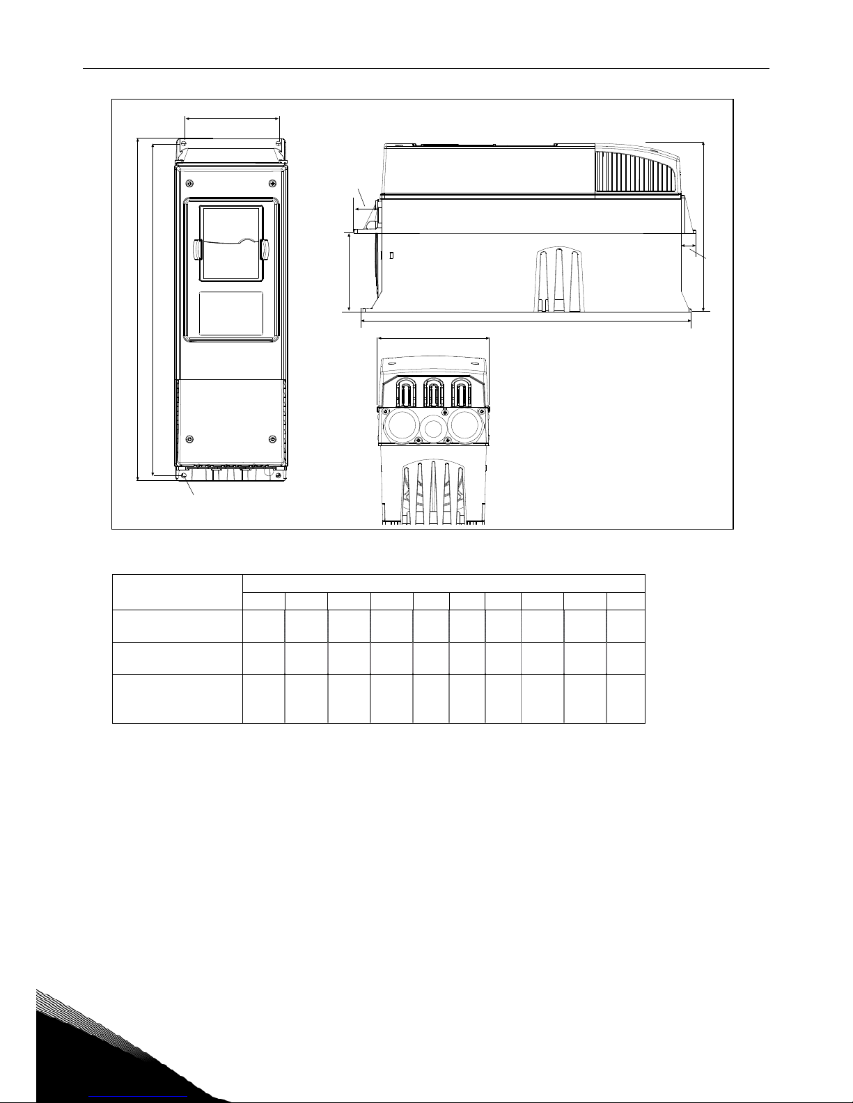
INSTALLATION vacon • 29
24-hour support +358 (0)201 212 575 • Email: vacon@vacon.com
5
Figure 5-1. Vacon NX_ dimensions
Type Dimensions [mm]
W1 W2 H1 H2 H3 D1
∅
E1∅ E2∅*
0004—0012 NX_2
0003—0012 NX_5
128 100 327 313 292 190 7 3 x 28,3
0017—0031 NX_2
0016—0031 NX_5
144 100 419 406 391 214 7 2 x 37 1 x 28,3
0048—0061 NX_2
0038—0061 NX_5
0004—0034 NX_6
195 148 558 541 519 237 9 3 x 37
0075—0114 NX_2
0072—0105 NX_5
0041—0052 NX_6
237 190 630 614 591 257 9 3 x 47
0140—0205 NX_2
0140—0205 NX_5
0062—0100 NX_6
291 255 758 732 721 344 9 3 x 59
Table 5-1. Dimensions for different frequency converter types
* = FR5 only
W1
W2
H1 H2
Ø
D1
H3
fr5ip21.fh8
Ø
E1Ø
E2Ø*
30 • vacon INSTALLATION
Tel. +358 (0)201 2121 • Fax +358 (0)201 212 205
5
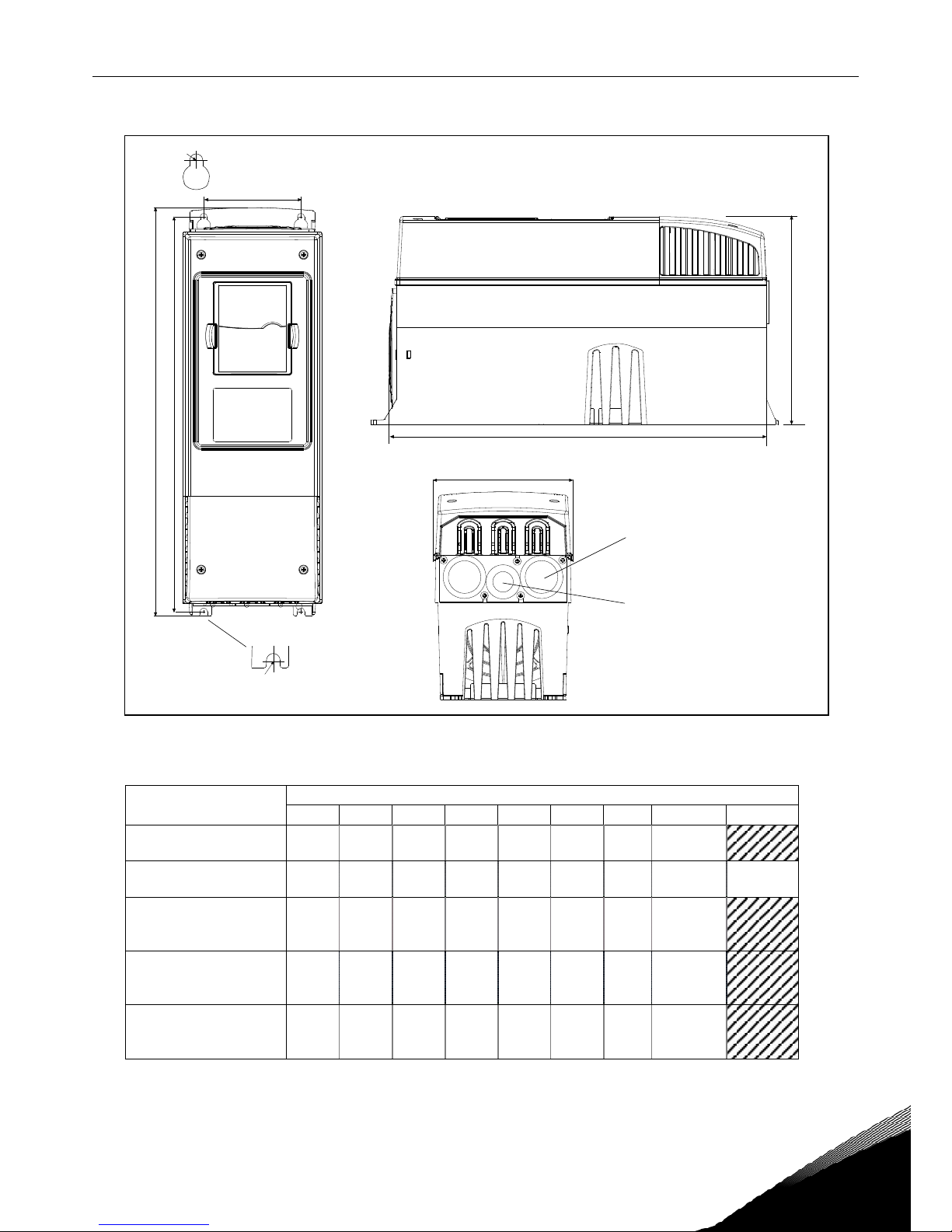
Figure 5-2. Vacon NX_ dimensions, FR4 to FR6; Flange mounting
Type Dimensions [mm]
W1 W2 H1 H2 H3 H4 H5 D1 D2
∅
0004—0012 NX_2
0003—0012 NX_5
128 113 337 325 327 30 22 190 77 7
0017—0031 NX_2
0016—0031 NX_5
144 120 434 420 419 36 18 214 100 7
0048—0061 NX_2
0038—0061 NX_5
0004—0034 NX_6
195 170 560 549 558 30 20 237 106 6.5
Table 5-2. Dimensions for different frequency converter types FR4 to FR6, flange mounting
W2
H1 H2
W1
D1
D2
H4
H5
fr5ip21kaulus.fh8
Ø
H3
 Loading...