

Page 1

Clearwater Tech - Phone: 800.894.0412 - Fax: 208.368.0415 - Web: www.clrwtr.com - Email: [email protected]
User's Manual
NX Inverters
FI4 - FI8
Page 2

AT LEAST THE 10 FOLLOWING STEPS OF THE
Clearwater Tech - Phone: 800.894.0412 - Fax: 208.368.0415 - Web: www.clrwtr.com - Email: [email protected]
START-UP QUICK GUIDE
MUST BE PERFORMED
DURING THE INSTALLATION AND COMMISSIONING.
IF ANY PROBLEMS OCCUR, PLEASE CONTACT YOUR LOCAL DISTRIBUTOR.
Start-up Quick Guide
1. Check that the delivery corresponds to your order, see Chapter 3.
2. Before taking any commissioning actions, read carefully the safety instructions in
Chapter 1.
3. Before the mechanical installation, check the minimum clearances around the unit and
check the ambient conditions in Chapter 5.
4. Check the size of the motor cable, DC supply cable, and mains fuses, and check the
cable connections. Read Chapters 6.1.1.1 – 6.1.1.6.
5. Follow the installation instructions, see Chapter 6.1.2.
6. The sizes and earthing of control connections are explained in Chapter 6.2.1.
7. If the Start-Up wizard is active, select the language you want the keypad and the
application to use and confirm by pressing the
active, follow the instructions in 7a and 7b below.
8. 7a. Select the language of the keypad from Menu M6, page 6.1. Instructions on using the
keypad are given in Chapter 7.
enter button. If the Start-Up wizard is not
9. 7b. Select the application you want to use from Menu M6, page 6.2. Instructions on using
the keypad are given in Chapter 7.
10. All parameters have factory default values. To ensure proper operation, check the rating
plate data for the values below and the corresponding parameters of parameter group
G2.1.
• nominal voltage of the motor
• nominal frequency of the motor
• nominal speed of the motor
• nominal current of the motor
• motor cosϕ
All parameters are explained in the All in One Application Manual.
11. Follow the commissioning instructions, see Chapter 8.
12. The Vacon NX Inverter is now ready for use.
Vacon Plc is not responsible for the use of the inverters against the
instructions.
Page 3

Clearwater Tech - Phone: 800.894.0412 - Fax: 208.368.0415 - Web: www.clrwtr.com - Email: [email protected]
CONTENTS
VACON NXI USER’S MANUAL
INDEX
1 SAFETY
2 EU DIRECTIVE
3 RECEIPT OF DELIVERY
4 TECHNICAL DATA
5 INSTALLATION
6 CABLING AND CONNECTIONS
7 CONTROL KEYPAD
8 COMMISSIONING
9 FAULT TRACING
Page 4

vacon • 3
Clearwater Tech - Phone: 800.894.0412 - Fax: 208.368.0415 - Web: www.clrwtr.com - Email: [email protected]
ABOUT THE VACON NXI USER'S MANUAL
AND THE ”All in One” APPLICATION MANUAL
Congratulations for choosing Vacon NX Inverters!
The User's Manual will provide you with the necessary information about the installation,
commissioning and operation of Vacon NX Inverters. We recommend that you carefully study these
instructions before powering up the inverter for the first time.
In the All in One Application Manual you will find information about the different applications
included in the All in One Application Package. Should these applications not meet the requirements
of your process, please contact the manufacturer for information on special applications.
This manual is available in both paper and electronic editions. We recommend you to use the
electronic version if possible. If you have the electronic version at your disposal, you will be able to
benefit from the following features:
The manual contains several links and cross-references to other locations in the manual, which
makes it easier to move around in the manual. The reader can thus easily find and check things.
The manual also contains hyperlinks to web pages. To visit these web pages through the links, you
must have an internet browser installed on your computer.
Page 5

4 • vacon
Clearwater Tech - Phone: 800.894.0412 - Fax: 208.368.0415 - Web: www.clrwtr.com - Email: [email protected]
Vacon NX User's Manual
Document code: ud01047B
Date: 9.11.2005
Index
SAFETY............................................................................................................................... 6
1.
1.1 Warnings ..................................................................................................................................... 6
1.2 Safety instructions...................................................................................................................... 6
1.3 Earthing and earth fault protection ........................................................................................... 7
1.4 Running the motor...................................................................................................................... 7
2. EU DIRECTIVE ....................................................................................................................8
2.1 CE marking ................................................................................................................................. 8
2.2 EMC directive .............................................................................................................................. 8
2.2.1 Introduction....................................................................................................................... 8
2.2.2 Technical criteria..............................................................................................................8
2.2.3 Vacon inverter EMC classification ................................................................................... 8
3. RECEIPT OF DELIVERY....................................................................................................... 9
3.1 Type designation code. ............................................................................................................... 9
3.1.1 FR4—FR8 .......................................................................................................................... 9
3.1.2 The standard features of NX inverters ...........................................................................10
3.2 Storage...................................................................................................................................... 11
3.3 Maintenance.............................................................................................................................. 11
3.4 Warranty.................................................................................................................................... 11
4. TECHNICAL DATA ............................................................................................................ 12
4.1 Introduction............................................................................................................................... 12
4.2 Power ratings............................................................................................................................ 14
4.2.1 Vacon NXI_xxxx 5 – Supply voltage 465-800 Vdc, Motor voltage 380—500 Vac ............14
4.2.2 Vacon NXI_xxxx 6 – Supply voltage 640-1100 Vdc, Motor voltage 525—690 Vac...........15
4.3 Technical information............................................................................................................... 16
5. INSTALLATION ................................................................................................................. 19
5.1 Mounting ................................................................................................................................... 19
5.2 Fan cooling................................................................................................................................ 25
5.2.1 Frames FR4 to FR8..........................................................................................................25
5.2.2 Power losses as function of switching frequency ..........................................................26
6. CABLING AND CONNECTIONS ......................................................................................... 27
6.1 Power unit................................................................................................................................. 27
6.1.1 Power connections ..........................................................................................................28
6.1.1.1 DC supply and motor cables ...................................................................................28
6.1.1.2 Control cable ...........................................................................................................28
6.1.1.3 Fuses, NXI_xxxx 5....................................................................................................29
6.1.1.4 Fuses, NXI_xxxx 6....................................................................................................29
6.1.1.5 Cable sizes, NXI_xxxx 5 ...........................................................................................30
6.1.1.6 Cable sizes, NXI_xxxx 6 ...........................................................................................30
6.1.2 Installation instructions ..................................................................................................31
6.1.2.1 Stripping lengths of motor and DC supply cables..................................................33
6.1.2.2 Vacon NX frames .....................................................................................................34
Tel : 0201-2121 • Fax: 0201-212 205
Page 6

vacon • 5
Clearwater Tech - Phone: 800.894.0412 - Fax: 208.368.0415 - Web: www.clrwtr.com - Email: [email protected]
6.1.3 Cable installation and the UL standards ........................................................................36
6.1.4 Cable and motor insulation checks ................................................................................36
6.2 Control unit ............................................................................................................................... 37
6.2.1 Control connections ........................................................................................................38
6.2.1.1 Control cables .........................................................................................................39
6.2.1.2 Galvanic isolation barriers ......................................................................................39
6.2.2 Control terminal signals .................................................................................................40
6.2.2.1 Digital input signal inversions.................................................................................41
6.2.2.2 Jumper selections on the NXOPTA1 basic board...................................................42
7. CONTROL KEYPAD ........................................................................................................... 44
7.1 Indicators on the keypad display.............................................................................................. 44
7.1.1 Drive status indications...................................................................................................44
7.1.2 Control place indicators ..................................................................................................45
7.1.3 Status LEDs (green – green – red).................................................................................45
7.1.4 Text lines..........................................................................................................................46
7.2 Keypad push-buttons................................................................................................................ 47
7.2.1 Button descriptions .........................................................................................................47
7.3 Navigation on the control keypad............................................................................................. 48
7.3.1 Monitoring menu (M1) .....................................................................................................50
7.3.2 Parameter menu (M2) .....................................................................................................51
7.3.3 Keypad control menu (M3) ..............................................................................................53
7.3.3.1 Selection of control place .......................................................................................53
7.3.3.2 Keypad reference ....................................................................................................54
7.3.3.3 Keypad direction......................................................................................................54
7.3.3.4 Stop button activated...............................................................................................54
7.3.4 Active faults menu (M4)...................................................................................................55
7.3.4.1 Fault types ...............................................................................................................55
7.3.4.2 Fault codes ..............................................................................................................57
7.3.4.3 Fault time data record.............................................................................................60
7.3.5 Fault history menu (M5) ..................................................................................................61
7.3.6 System menu (M6)...........................................................................................................62
7.3.6.1 Selection of language ..............................................................................................65
7.3.6.2 Application selection ...............................................................................................65
7.3.6.3 Copy parameters .....................................................................................................66
7.3.6.4 Parameter comparison ...........................................................................................68
7.3.6.5 Safety .......................................................................................................................69
7.3.6.6 Keypad settings .......................................................................................................71
7.3.6.7 Hardware settings ...................................................................................................73
7.3.6.8 System info ..............................................................................................................75
7.3.7 Expander board menu (M7).............................................................................................79
7.4 Further keypad functions ......................................................................................................... 80
8. COMMISSIONING.............................................................................................................. 81
8.1 Safety......................................................................................................................................... 81
8.2 Commissioning the inverter..................................................................................................... 81
9. FAULT TRACING............................................................................................................... 84
Page 7
6 • vacon SAFETY
Clearwater Tech - Phone: 800.894.0412 - Fax: 208.368.0415 - Web: www.clrwtr.com - Email: [email protected]
1. SAFETY
ONLY A COMPETENT ELECTRICIAN MAY CARRY OUT
THE ELECTRICAL INSTALLATION
1.1 Warnings
WARNING
1
2
3
4
5
6
1.2 Safety instructions
1
2
3
4
5
6
7
The components of the power unit of the inverter are live when the Vacon
NX is connected to DC supply. Coming into contact with this voltage is
extremely dangerous and may cause death or severe injury. The
control unit is isolated from mains potential.
The supply and motor terminals are live when the Vacon NX is connected
to DC supply, even if the motor is not running.
The control I/O-terminals are isolated from the mains potential.
However, the relay outputs and other I/O-terminals may have dangerous
control voltage present even when the Vacon NX is disconnected from the
DC supply.
.
The inverter has a large capacitive leakage current.
If the inverter is used as a part of a machine, the machine manufacturer
is responsible for providing the machine with a main switch (EN 60204-1).
Only spare parts delivered by Vacon can be used.
The Vacon NX inverter is meant for fixed installations only.
Do not perform any measurements when the inverter is connected to the
DC supply.
After having disconnected the inverter from the DC supply, wait until the
fan stops and the indicators on the keypad go out (if no keypad is
attached see the indicator through the keypad base). Wait 5 more
minutes before doing any work on Vacon NX connections. Do not even
open the cover before this time has expired.
Do not perform any voltage withstand tests on any part of Vacon NX.
There is a certain procedure according to which the tests shall be performed. Ignoring this procedure may result in damaged product.
Prior to measurements on the motor or the motor cable, disconnect the
motor cable from the inverter.
Do not touch the components on the circuit boards. Static voltage discharge may damage the components.
Before connecting the inverter to DC supply, make sure that the Vacon
NX front and cable covers are closed.
Tel: +358-201-2121 • Fax: +358-201-212 205
1
Page 8
SAFETY vacon • 7
Clearwater Tech - Phone: 800.894.0412 - Fax: 208.368.0415 - Web: www.clrwtr.com - Email: [email protected]
1.3 Earthing and earth fault protection
The Vacon NX inverter must always be earthed with an earthing conductor connected to the earthing
terminal.
The earth fault protection inside the inverter only protects the inverter against earth faults in the
motor or the motor cable.
Due to the high capacitive currents present in the inverter, fault current protective switches may not
function properly. If fault current protective switches are used, they need to be tested with earth
fault currents present during possible fault situations.
1.4 Running the motor
Warning symbols
For your own safety, please pay special attention to the instructions marked with the following
symbols:
WARNING
HOT SURFACE
MOTOR RUN CHECK LIST
WARNING
Dangerous voltage
=
=
General warning
Hot surface – Risk of burn
=
1
2
3
4
5
Before starting the motor, check that the motor is mounted properly and
ensure that the machine connected to the motor allows the motor to be
started.
Set the maximum motor speed (frequency) according to the motor and
the machine connected to it.
Before reversing the motor, make sure that this can be done safely.
Make sure that no power correction capacitors are connected to the
motor cable.
Make sure that the motor terminals are not connected to mains
potential.
1
Page 9

8 • vacon eu directive
Clearwater Tech - Phone: 800.894.0412 - Fax: 208.368.0415 - Web: www.clrwtr.com - Email: [email protected]
2. EU DIRECTIVE
2.1 CE marking
The CE marking on the product guarantees the free movement of the product within the EEA
(European Economic Area). It also guarantees that the product complies with applicable directives
(for example, the EMC directive and other possible so-called new method directives).
Vacon NX inverters carry the CE label as a proof of compliance with the Low Voltage Directive (LVD)
and the Electro Magnetic Compatibility (EMC) directive. SGS FIMKO has acted as the Competent
Body.
2.2 EMC directive
2.2.1 Introduction
The EMC Directive provides that the electrical apparatus must not excessively disturb the
environment it is used in, and, on the other hand, it shall have an adequate level of immunity toward
other disturbances from the same environment.
The compliance of Vacon NX inverters with the EMC directive is verified with Technical Construction
Files (TCF) and checked and approved by SGS FIMKO, which is a Competent Body. The Technical
Construction Files are used to authenticate the conformity of Vacon inverters with the Directive
because it is impossible to test such a large product family in a laboratory environment and because
the combinations of installation vary greatly.
2.2.2 Technical criteria
Our basic idea was to develop a range of inverters offering the best possible usability and costefficiency. EMC compliance was a major consideration from the outset of the design.
Vacon NX inverters are marketed throughout the world, a fact which makes the EMC requirements
of customers different. As far as immunity is concerned, all Vacon NX inverters are designed to fulfil
even the strictest requirements.
2.2.3 Vacon inverter EMC classification
Factory delivered Vacon NX inverters are Class T equipment, which fulfil all EMC immunity
requirements (standards EN 50082-1, 50082-2 and EN 61800-3).
Class T:
Class T equipment have a small earth leakage current and can be used with floating DC input. If they
are used with other supplies, no EMC requirements are complied with.
Warning: This product is of the restricted sales distribution class according to IEC 61800-3. In
residential areas, this product may cause radio interference in which case the user may be required
to take adequate measures.
Tel: +358-201-2121 • Fax: +358-201-212 205
2
Page 10
receipt of delivery vacon • 9
Clearwater Tech - Phone: 800.894.0412 - Fax: 208.368.0415 - Web: www.clrwtr.com - Email: [email protected]
3. RECEIPT OF DELIVERY
Vacon NX inverters have undergone scrupulous tests and quality checks at the factory before they
are delivered to the customer. However, after unpacking the product, check that no signs of
transportation damage is to be found on the product and that the delivery is complete (compare the
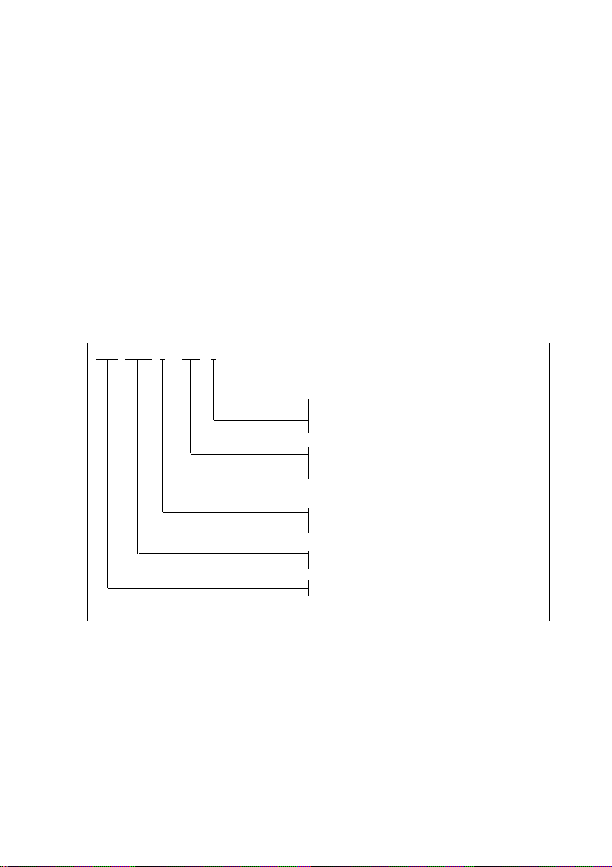
type designation of the product to the code below, see Figure 3-1
Should the drive have been damaged during the shipping, please contact primarily the cargo
insurance company or the carrier.
If the delivery does not correspond to your order, contact the supplier immediately.
3.1 Type designation code.
3.1.1 FR4—FR8
NX
I
0000 5
Nominal mains voltage:
5 = 465...800VDC, 6 = 640...1100VDC
Nominal current
esim. 0004 = 4 A, 0022 = 22 A
Reserved for cooling method, now always air cooling:
_ = air cooling (= no sym bo l)
W = liquid cooling
Code: I = Inverter Unit (INU)
Product series: NX
nxik2.fh8
Figure 3-1 Vacon NX type designation code, FR4—FR8
3
Page 11
10 • vacon receipt of delivery
Clearwater Tech - Phone: 800.894.0412 - Fax: 208.368.0415 - Web: www.clrwtr.com - Email: [email protected]
3.1.2 The standard features of NX inverters
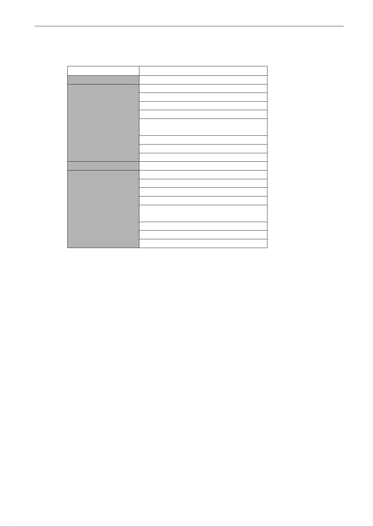
Sales code NXI_AAAA 5/6 Standard features FR4, FR6 and FR7
Sales code NXI_AAAA 5/6 Standard features FR8
Table 3-1. The standard features of NX inverters
DC connection
IP21
Air cooling
Integrated charging
Alphanumeric control panel (in the
front of the module)
I/O modules A1 & A2
Standard board
Safety CE / UL
DC connection
IP00
Air cooling
Integrated charging
Alphanumeric control panel (in the
front of the module)
I/O modules A1 & A2
Standard board
Safety CE / UL
INU
Tel: +358-201-2121 • Fax: +358-201-212 205
3
Page 12

receipt of delivery vacon • 11
Clearwater Tech - Phone: 800.894.0412 - Fax: 208.368.0415 - Web: www.clrwtr.com - Email: [email protected]
3.2 Storage
If the inverter is to be stored before use, make sure that the ambient conditions are acceptable:
Storage temperature –40…+70
Relative humidity <95%, no condensation
If the inverter is stored for over 12 months, contact Vacon service before connecting the inverter to
the power supply.
3.3 Maintenance
In normal conditions, Vacon NX inverters are maintenance-free. However, we recommend to clean
the heatsink with compressed air whenever necessary. The cooling fan can easily be changed if
necessary.
It may also be necessary to check the tightening torques of terminals at certain intervals.
3.4 Warranty
Only manufacturing defects are covered by the warranty. The manufacturer assumes no
responsibility for damages caused during or resulting from transport, receipt of the delivery,
installation, commissioning or use.
The manufacturer shall in no event and under no circumstances be held responsible for damages
and failures resulting from misuse, wrong installation, unacceptable ambient temperature, dust,
corrosive substances or operation outside the rated specifications.
Neither can the manufacturer be held responsible for consequential damages.
The Manufacturer's warranty period is 18 months from the delivery or 12 months from the
commissioning whichever expires first (General delivery terms NL92/Orgalime S92).
The local distributor may grant a warranty time different from the above. This warranty time shall be
specified in the distributor's sales and warranty terms. Vacon assumes no responsibility for any
other warranties than that granted by Vacon itself.
In all matters concerning the warranty, please contact your distributor first.
°C
3
Page 13
12 • vacon technical data
Clearwater Tech - Phone: 800.894.0412 - Fax: 208.368.0415 - Web: www.clrwtr.com - Email: [email protected]
4. TECHNICAL DATA
4.1 Introduction
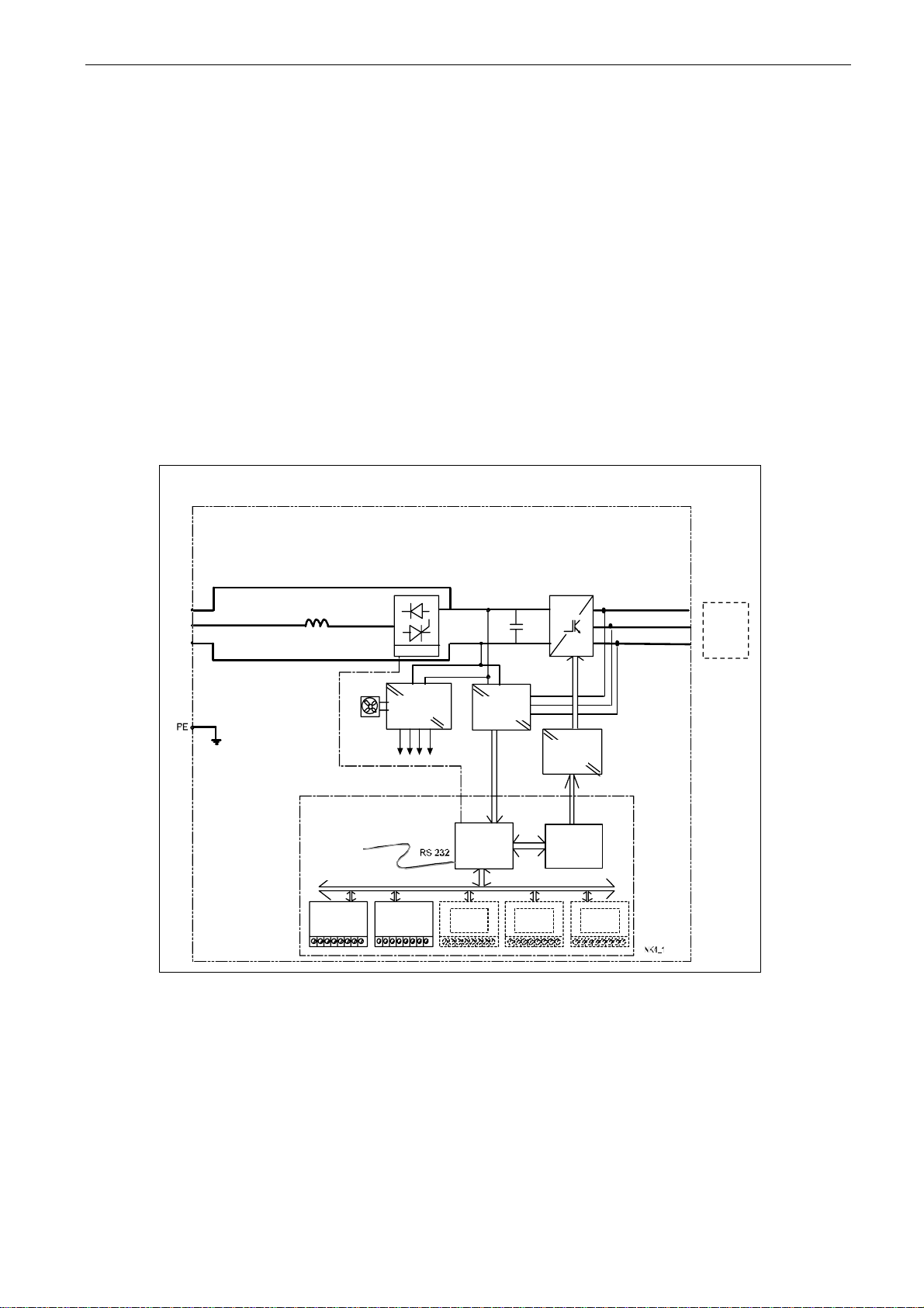
The figure below presents the block diagram of the Vacon NX inverter. The inverter mechanically
consists of two units, the Power Unit and the Control Unit.
The Power Unit contains an inverter bridge which consists of IGBT switches and produces a
symmetrical, 3-phase PWM-modulated AC voltage to the motor. To protect the DC-link capacitors,
the Power Unit also contains a charging circuit for controlled DC-link charge. Use the B+ and DCterminals in order to bypass the charging circuit.
The Motor and Application Control Block is based on microprocessor software. The microprocessor
controls the motor based on the information it receives through measurements, parameter settings,
control I/O and control keypad. The motor and application control block controls the motor control
ASIC which, in turn, calculates the IGBT positions. Gate drivers amplify these signals for driving the
IGBT inverter bridge.
Power
module
Mains
B+
DC+
DC-
Integrat ed char ging c i r cuit
Control
Keypad
Control
module
Control
I/O
Fan
Charg.res.
Power
Supply
Control
I/O
Measurements
Motor and
Application
Control
Control
I/O
Control
I/O
Figure 4-1. The block diagram of Vacon NX inverter
IGBT
Inverter
=
3~
Gate
Drivers
Motor
Control
ASIC
Current
Sensors
Control
I/O
Motor
U
V
W
Output
EMCfilter
Tel: +358-201-2121 • Fax: +358-201-212 205
4
Page 14

technical data vacon • 13
Clearwater Tech - Phone: 800.894.0412 - Fax: 208.368.0415 - Web: www.clrwtr.com - Email: [email protected]
The control keypad constitutes a link between the user and the inverter. The control keypad is used
for parameter setting, reading status data and giving control commands. It is detachable and can be
operated externally and is connected via a cable to the inverter. Instead of the control keypad, a PC
can be used to control the inverter if connected through a similar cable (VACON RS232PC –1.5M).
The basic control interface and the parameters (the Basic Application) are easy to use. If a more
versatile interface or parameters are required, a more suitable application can be chosen from the
"All in One+" Application Package. See the "All in One+" Application Manual for more information on
the different applications.
Optional I/O expander boards that increase the number of inputs and outputs to be used are also
available. For more information, contact the Manufacturer or your local distributor (see back cover).
4
Page 15
14 • vacon technical data
Clearwater Tech - Phone: 800.894.0412 - Fax: 208.368.0415 - Web: www.clrwtr.com - Email: [email protected]
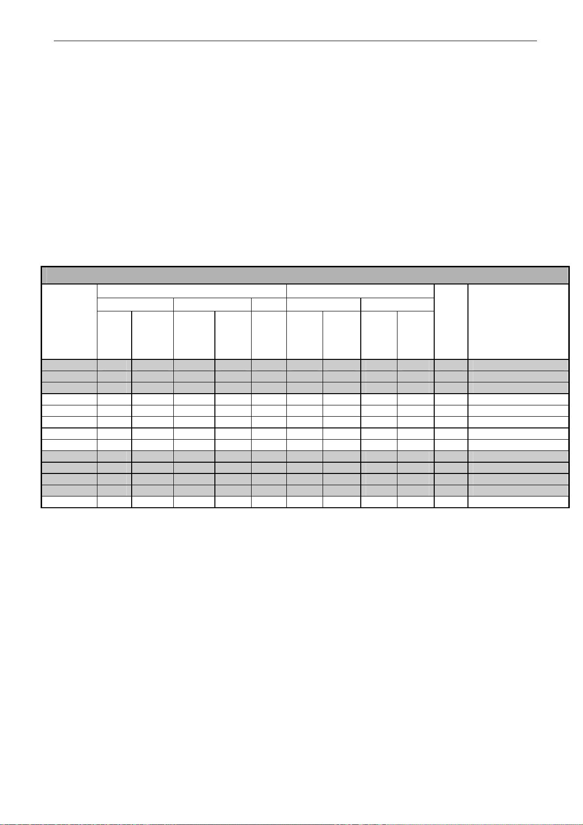
4.2 Power ratings
4.2.1 Vacon NXI_xxxx 5 – Supply voltage 465-800 Vdc, Motor voltage 380—500 Vac
High overload = Max current IS, 2 sec/20 sec, 150% overloadability, 1 min/10 min
Following continuous operation at rated output current, 150 % rated output
current (IH) for 1 min, followed by a period of load current less than rated
current, and of such duration that the r.m.s output current, over the duty cycle,
does not exceed rated output current (IH)
Low overload = Max current IS, 2 sec/20 sec, 110% overloadability, 1 min/10 min
Following continuous operation at rated output current, 110% rated output
current (IL) for 1 min, followed by a period of load current less than rated
current, and of such duration that the r.m.s output current, over the duty cycle,
does not exceed rated output current (IL)
Frames FR4…7 are available as IP21 and FR8 as IP 00
Motor voltage 380-500 Vac, 50/60 Hz, 3~
Inverter type
Low High
Rated
continuo
us
current
I
(A)
L
NXI _0004 5 4.3 4.7 3.3 5 6.2 1.5 1.1 2.2 1.5 FR4 128x292x190/5 NXI _0009 5 9 9.9 7.6 11.4 14 4 3 5.5 4 FR4 128x292x190/5 NXI _0012 5 12 13.2 9 13.5 18 5.5 4 7.5 5.5 FR4 128x292x190/5 NXI _0016 5 16 17.6 12 18 24 7.5 5.5 11 7.5 FR6 195x519x237/16 NXI _0022 5 23 25.3 16 24 32 11 7.5 15 11 FR6 195x519x237/16 NXI _0031 5 31 34 23 35 46 15 11 18.5 15 FR6 195x519x237/16 NXI _0038 5 38 42 31 47 62 18.5 15 22 18.5 FR6 195x519x237/16 NXI _0045 5 46 51 38 57 76 22 18.5 30 22 FR6 195x519x237/16 NXI _0061 5 61 NXI _0072 5 72 79 61 92 122 37 30 45 37 FR7 237x591x257/29 NXI _0087 5 87 96 72 108 144 45 37 55 45 FR7 237x591x257/29 NXI _0105 5 105 116 87 131 174 55 45 75 55 FR7 237x591x257/29 NXI _0140 5 140 154 105 158 210 75 55 90 75 FR8 285x721x288/48
Table 4-1. Power ratings and dimensions of Vacon NX, supply voltage 465—800Vdc
Loadability Motor shaft power
513Vdc supply 675Vdc supply
10%
overload
current
(A)
Rated
continuou
s current
I
(A)
H
50%
overload
current
(A)
Max
current
I
S
10%
overload
40°C
P(kW)
50%
overload
50°C
P(kW)
10%
overload
40°C
P(kW)
67 46 69 92 30 22 37 30 FR7 237x591x257/29
50%
overload
50°C
P(kW)
Frame
Dimensions and
weight
WxHxD/kg
Note: The rated currents in given ambient temperatures are achieved only when the switching
frequency is equal to or less than the factory default.
Tel: +358-201-2121 • Fax: +358-201-212 205
4
Page 16
technical data vacon • 15
Clearwater Tech - Phone: 800.894.0412 - Fax: 208.368.0415 - Web: www.clrwtr.com - Email: [email protected]
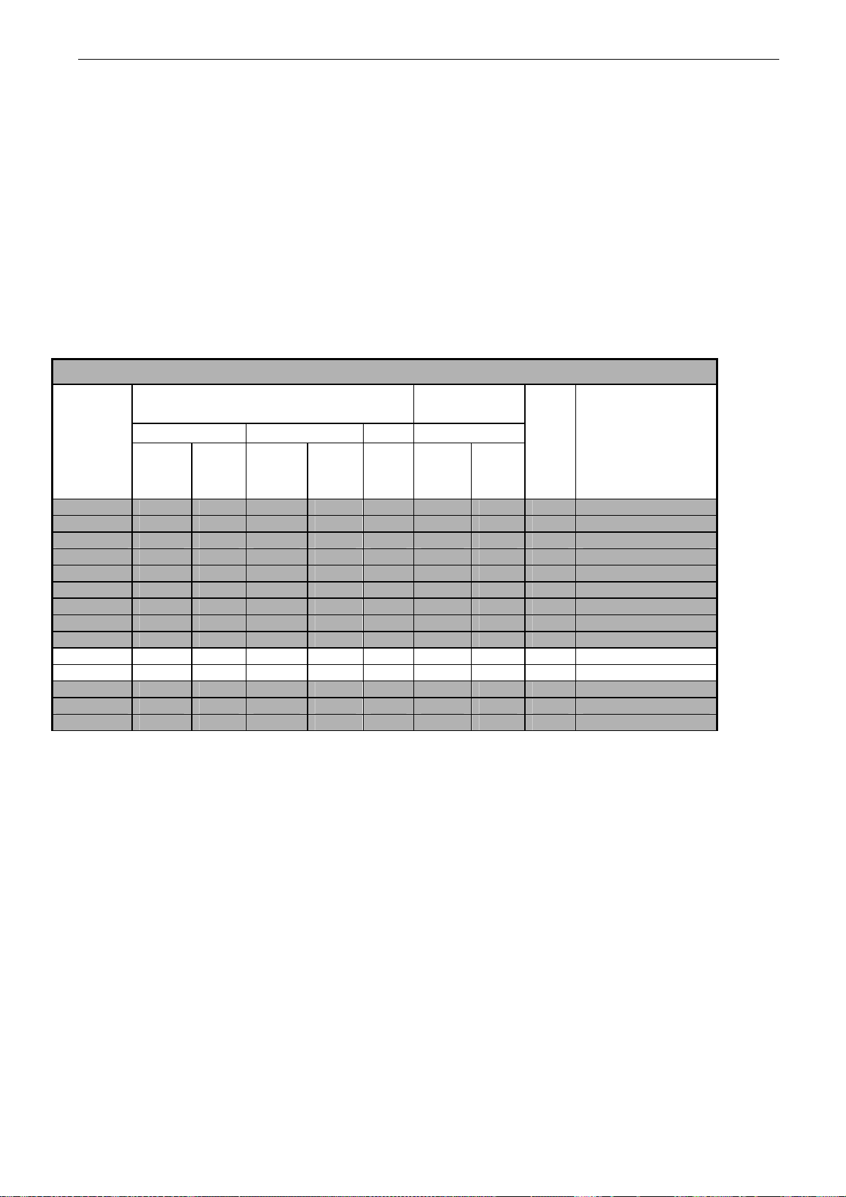
4.2.2 Vacon NXI_xxxx 6 – Supply voltage 640-1100 Vdc, Motor voltage 525—690 Vac
High overload = Max current IS, 2 sec/20 sec, 150% overloadability, 1 min/10 min
Following continuous operation at rated output current, 150 % rated output
current (IH) for 1 min, followed by a period of load current less than rated
current, and of such duration that the r.m.s output current, over the duty cycle,
does not exceed rated output current (IH)
Low overload = Max current IS, 2 sec/20 sec, 110% overloadability, 1 min/10 min
Following continuous operation at rated output current, 110% rated output
current (IL) for 1 min, followed by a period of load current less than rated
current, and of such duration that the r.m.s output current, over the duty cycle,
does not exceed rated output current (IL)
Frames FR4…7 are available as IP21 and FR8 as IP 00
Motor voltage 525-690 Vac, 50/60 Hz, 3~
Inverter type
Low High
Rated
continuous
current I
NXI _0004 6 4.5 5 3.2 5 6.7 3 2.2 FR6 195x519x237/16 NXI _0005 6 5.5 6.1 4.5 6.8 9 4 3 FR6 195x519x237/16 NXI _0007 6 7.5 8.3 5.5 8.3 11 5.5 4 FR6 195x519x237/16 NXI _0010 6 10 11 7.5 11.3 15 7.5 5.5 FR6 195x519x237/16 NXI _0013 6 13.5 14.9 10 15 20 11 7.5 FR6 195x519x237/16 NXI _0018 6 18 19.8 13.5 20.3 27 15 11 FR6 195x519x237/16 NXI _0022 6 22 24.2 18 27 36 18.5 15 FR6 195x519x237/16 NXI _0027 6 27 29.7 22 33 44 22 18.5 FR6 195x519x237/16 NXI _0034 6 34 37 27 41 54 30 22 FR6 195x519x237/16 NXI _0041 6 41 45 34 51 68 37.5 30 FR7 237x591x257/29 NXI _0052 6 52 57 41 62 82 45 37,5 FR7 237x591x257/29 NXI _0062 6 62 68 52 78 104 55 45 FR8 285x721x288/48 NXI _0080 6 80 88 62 93 124 75 55 FR8 285x721x288/48 NXI _0100 6 100 110 80 120 160 90 75 FR8 285x721x288/48
(A)
L
Loadability Motor shaft
930Vdc supply
10%
overload
current
(A)
Rated
continuou
s current
I
(A)
H
50%
overload
current
(A)
Max
current
I
S
10%
overload
40°C
P(kW)
power
50%
overload
50°C
P(kW)
Table 4-2. Power ratings and dimensions of Vacon NX, supply voltage 640—1100Vdc
Frame
Dimensions and weight
WxHxD/kg
Note: The rated currents in given ambient temperatures are achieved only when the switching
frequency is equal to or less than the factory default.
4
Page 17
16 • vacon technical data
Clearwater Tech - Phone: 800.894.0412 - Fax: 208.368.0415 - Web: www.clrwtr.com - Email: [email protected]
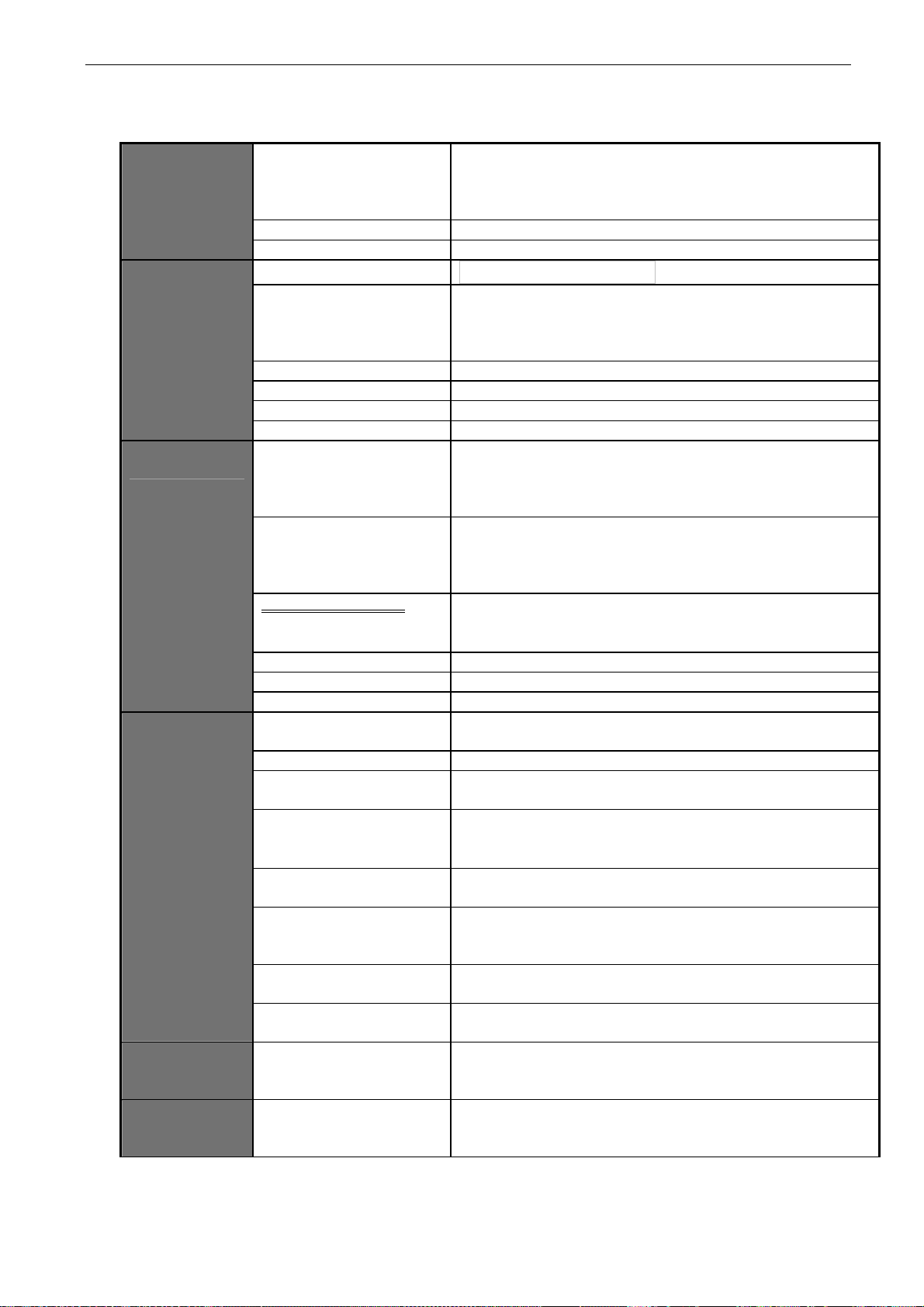
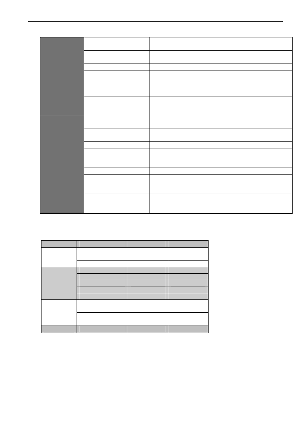
4.3 Technical information
DC connection
Motor connection
Control characteristics
Ambient conditions
EMC
(at default
settings)
Safety
Input voltage Uin 465...800Vdc; 640...1100Vdc; –0%…+0% , the ripple voltage
of the inverter supply voltage generated during the
rectification of the fundamental frequency AC voltage must
be less than 50Vp-p.
Connection to DC supply Once per minute or less (normal)
Starting delay FR4–FR8: 2 s
Output voltage
Continuous output current
3 ~ 0 - U
IH: Ambient temperature max. +50°C,
overload 1.5 x I
: Ambient temperature max. +40°C,
I
L
overload 1.1 x I
/ 1.4
in
(1 min./10 min.)
H
(1 min./10 min.)
L
Starting torque IS for two seconds, depends on the motor Starting current IS for 2 s every 20 s Output frequency 0…320 Hz; 7200 Hz (special use) Frequency resolution Depends on application Control method Frequency control U/f
Open Loop Sensorless Vector Control
Closed Loop Frequency Control
Closed Loop Vector Control
Switching frequency
(see parameter 2.6.9)
NXI_xxxx 5: 1…16 kHz; Factory default 10 kHz
NXI_0072 and greater:
1…10 kHz; Factory default 3.6 kHz
NXI_xxxx 6: 1…6 kHz; Factory default 1.5 kHz
Frequency reference
Analogue input
Panel reference
Resolution 0.1% (10-bit), accuracy ±1%
Resolution 0.01 Hz Field weakening point 30…320 Hz Acceleration time 0…3000 sec Deceleration time 0…3000 sec Ambient operating temperature
–10°C (no frost)…+50°C: IH (FR10: max. +40ºC)
–10°C (no frost)…+40°C: I
L
Storage temperature –40°C…+70°C Relative humidity 0 to 95% RH, non-condensing, non-corrosive,
no dripping water
Air quality:
- chemical vapours
- mechanical particles
IEC 721-3-3, unit in operation, class 3C2
IEC 721-3-3, unit in operation, class 3S2 Altitude 100% load capacity (no derating) up to 1,000 m
1-% derating for each 100m above 1000.; max. 3000m Vibration EN50178/EN60068-2-6
5…150 Hz
Displacement amplitude 0,25 mm (peak) at 5…15.8 Hz
Max acceleration amplitude 1 G at 15.8…150 Hz
Shock
EN50178, EN60068-2-27
UPS Drop Test (for applicable UPS weights)
Storage and shipping: max. 15 G, 11 ms (in package) Enclosure class FR4…7 IP21/NEMA1 standard
FR8 IP 00 standard Immunity Fulfils all EMC standards
EN 50178 (1997), EN 60204-1 (1996), EN 60950 (2000, 3
rd
edition) (as relevant), CE, UL, CUL, FI, GOST R, IEC 61800-5;
(see unit nameplate for more detailed approvals)
Tel: +358-201-2121 • Fax: +358-201-212 205
4
Page 18
technical data vacon • 17
Clearwater Tech - Phone: 800.894.0412 - Fax: 208.368.0415 - Web: www.clrwtr.com - Email: [email protected]
Control connections
Protections
Analogue input voltage
Analogue input current
Digital inputs (6) Positive or negative logic; 18…30VDC
Auxiliary voltage +24V, ±15%, max. 250mA
Output reference voltage +10V, +3%, max. load 10mA
Analogue output
Digital outputs Open collector output, 50mA/48V Relay outputs 2 programmable change-over relay outputs
Overvoltage trip limit
Undervoltage trip limit
Earth fault protection In case of earth fault in motor or motor cable, only the
Output phase supervision Trips if any of the output phases is missing
Overcurrent protection Yes
Unit overtemperature
protection
Motor overload protection Yes
Motor stall protection Yes
Motor underload
protection
Short-circuit protection of
+24V and +10V reference
voltages
Table 4-3. Technical information
0…+10V, R
Resolution 0.1%, accuracy ±1%
0(4)…20 mA, R
0(4)…20mA; R
Accuracy ±2%
Switching capacity 24VDC/8A, 250VAC/8A, 125VDC/0.4A
Min.switching load: 5V/10mA
NXI_5: 911VDC; NXI_6: 1200VDC
NXI_5: 333VDC; NXI_6: 460 VDC
inverter is protected
Yes
Yes
Yes
= 200kΩ, (–10V…+10V joystick control)
i
= 250Ω differential
i
max. 500Ω; Resolution 10bit;
L
Structure Inom (output) Motor cos Idc (input)
FR4
FR6
FR7
FR8
4.3 0.79 4.4
9 0.82 9.6
12 0.83 1.0 16 0.84 17.5 22 0.85 24.4 31 0.85 34.3 38 0.86 43 45 0.86 50 61 0.86 68 72 0.87 82
87 0.87 99 105 0.87 119 140 0.88 160
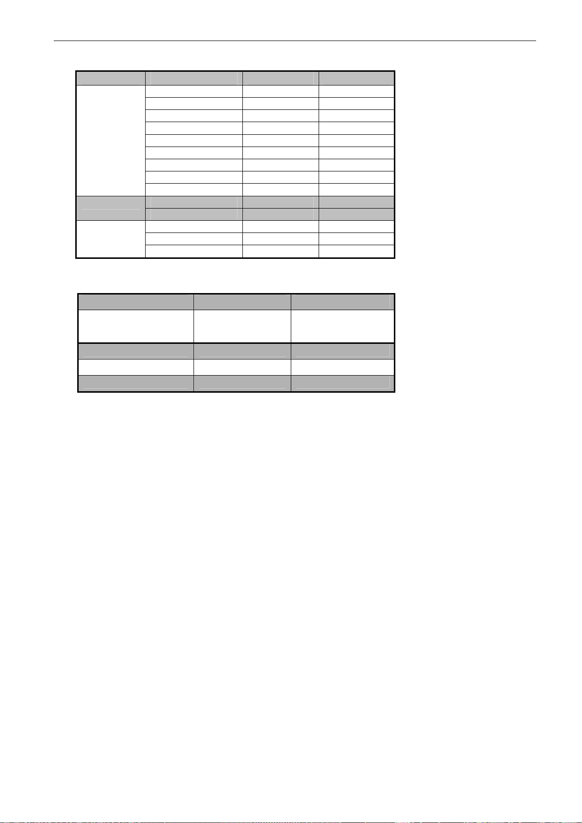
Table 4- 4 DC currents of Vacon NX, supply voltage 465 - 800Vdc
4
Page 19
18 • vacon technical data
Clearwater Tech - Phone: 800.894.0412 - Fax: 208.368.0415 - Web: www.clrwtr.com - Email: [email protected]
Structure Inom (output) Motor cos Idc (input)
FR6
FR7
FR8
4,5 0,81 4,7
5,5 0,82 5,9
7,5 0,83 8,1 10,0 0,84 10,9 13,5 0,85 14,9 18,0 0,85 19,9
22, 0,86 24,6 27,0 0,86 30,2 34,0 0,86 38,1 41,0 0,87 46 52,0 0,87 59 62,0 0,87 70 80,0 0,88 92
100,0 0,88 115
Table 4- 5. DC currents of Vacon NX, supply voltage 640 - 1100Vdc
Structure
FR4 0003-0007
FR4 0009-0012
NXI_xxxx 5 / µF NXI_xxxx 6 / µF
165
235
FR6 1000 500 FR7 1650 900 FR8 3300 1800
Table 5- 1. DC-link capacitance by structure.
Page 20

installation vacon • 19
Clearwater Tech - Phone: 800.894.0412 - Fax: 208.368.0415 - Web: www.clrwtr.com - Email: [email protected]
5. INSTALLATION
5.1 Mounting
The inverter can be mounted in either a vertical or horizontal position on a wall or on the back plane
of a cubicle. Enough space must be reserved around the inverter to ensure sufficient cooling, see
Figure 5-6. You must follow the minimum dimensions for installation, see Table 5-6 and Table 5-7.
Also make sure that the mounting plane is relatively even.
The inverter is fixed with four screws (or bolts, depending on the unit size). The dimensions for
installation are presented in Figure 5-6 and Table 5-6.
Lift units bigger than FR7 out of the package using a jib crane. Ask the factory or your local
distributor for information on how to lift the unit safely.
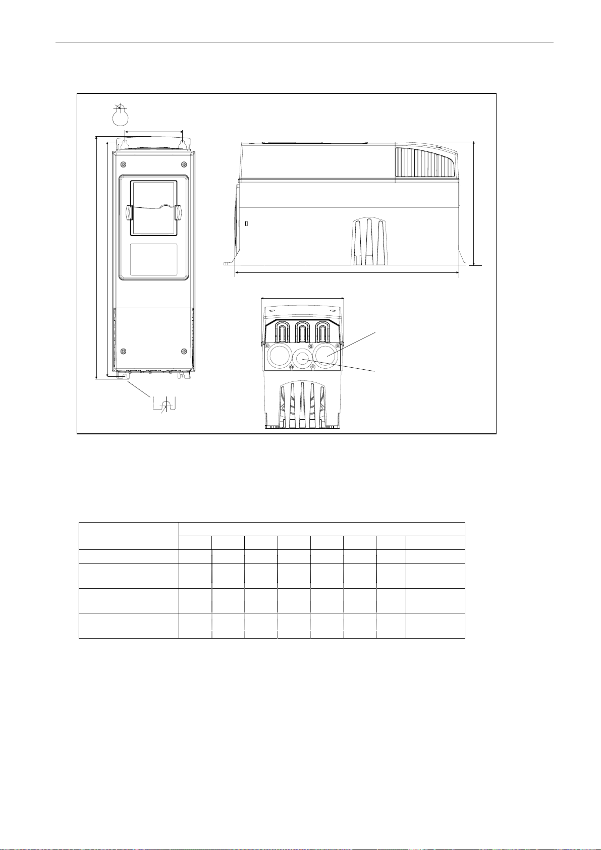
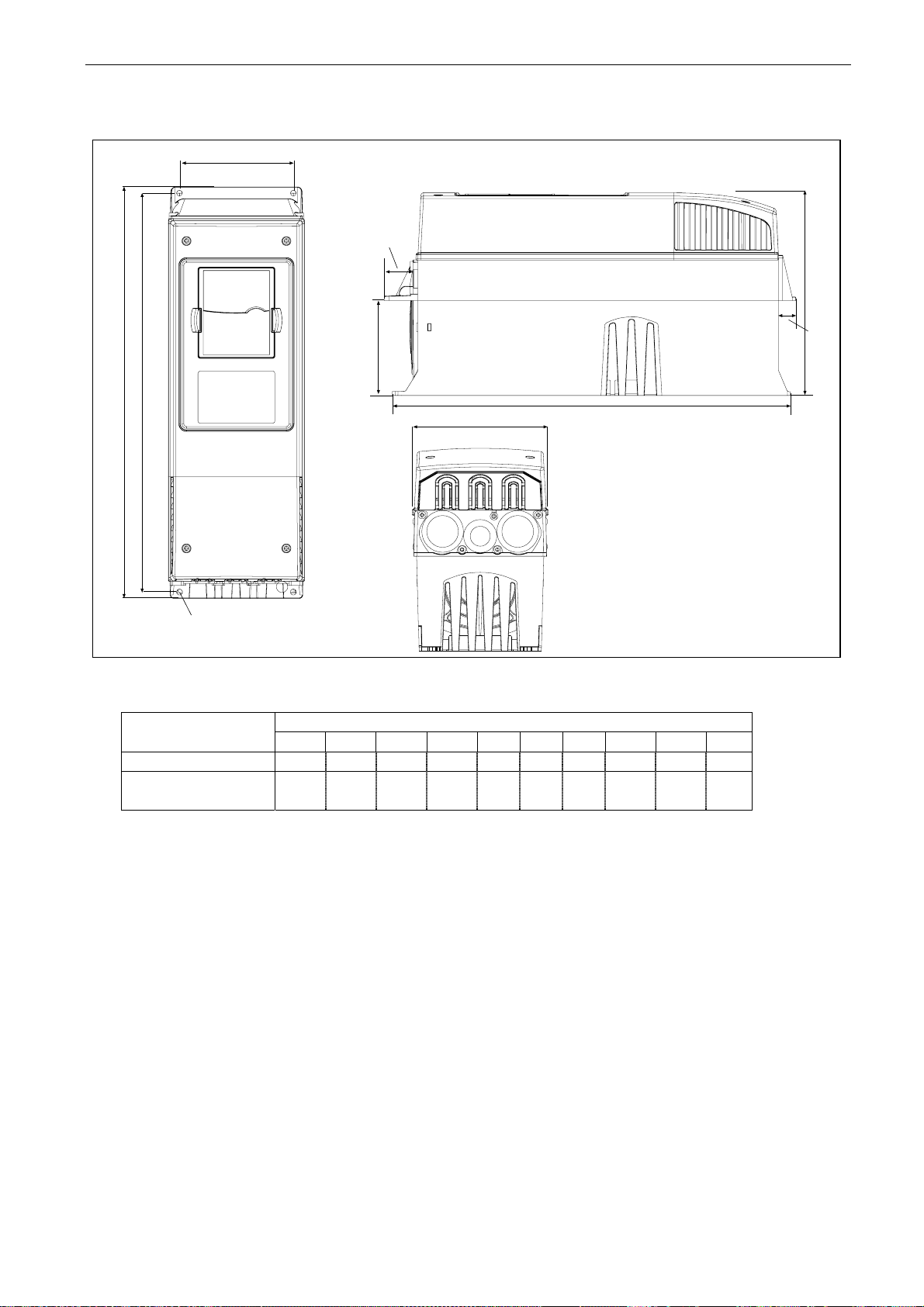
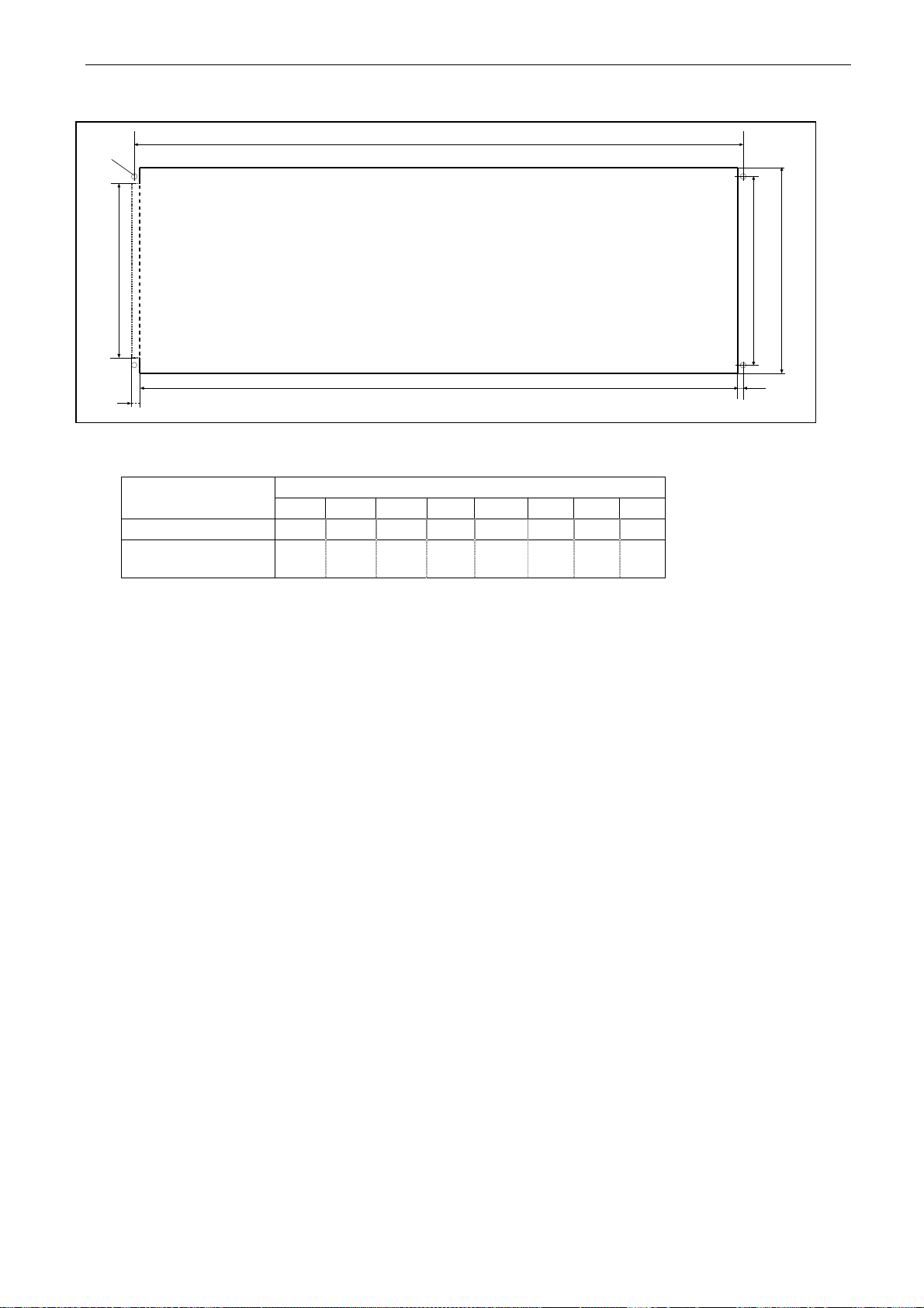
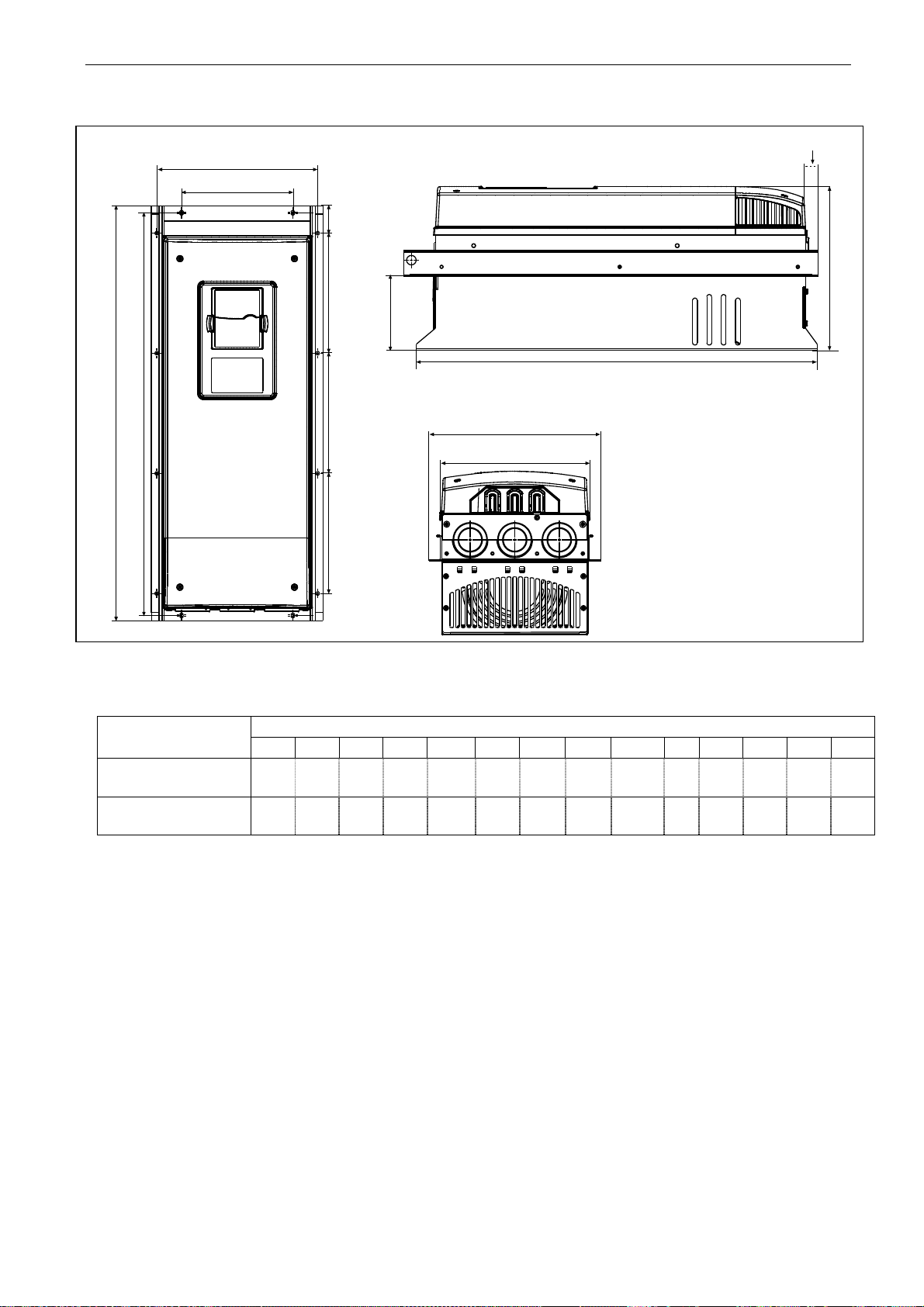
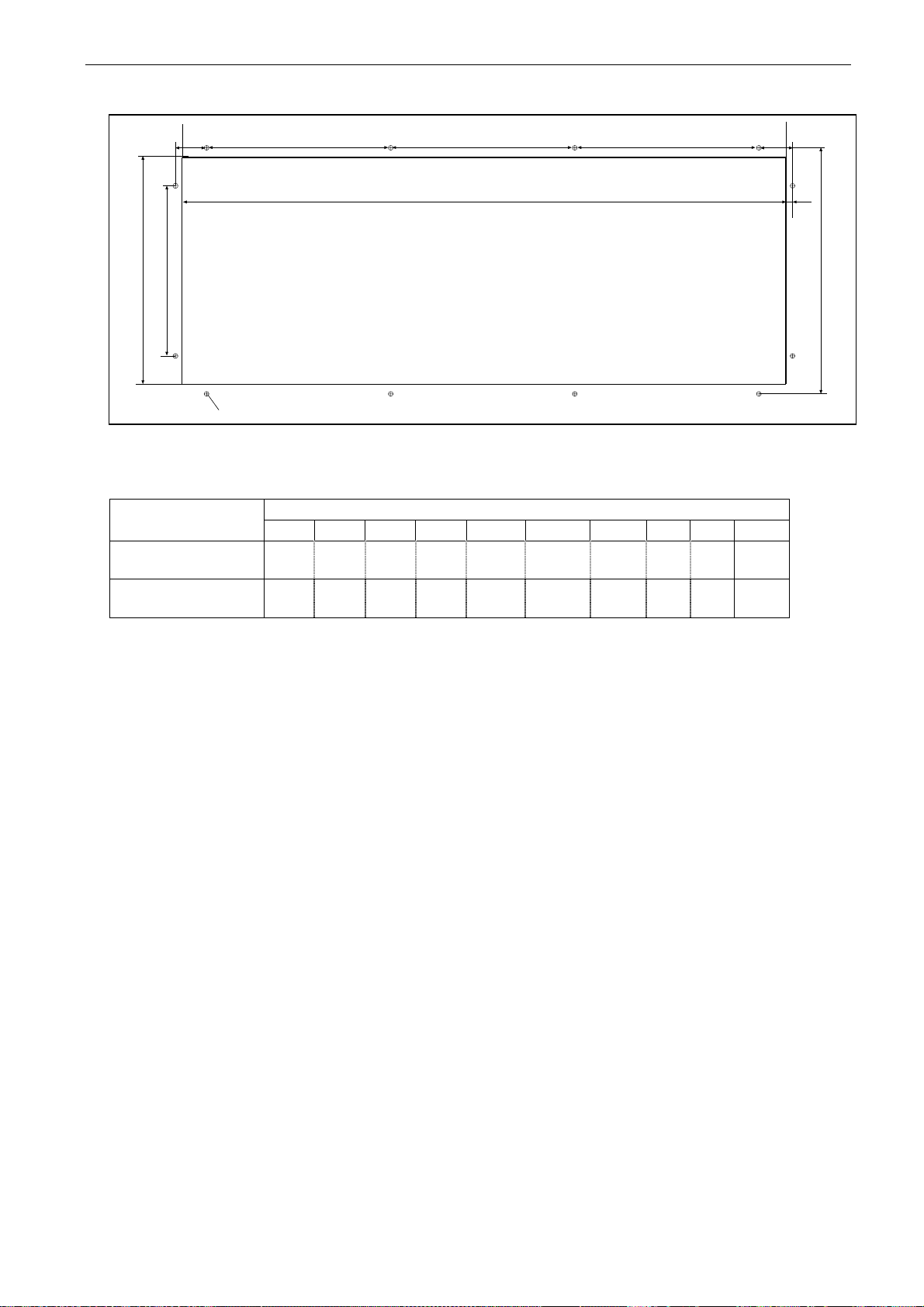
The following pages show the dimensions for Vacon NX with a default enclosure in Figure 5-1, and
with flange mounting in Figures 5-2 and Figure 5-4. Dimensions for the opening needed in flange
mounting are given in Table 5-3 and Table 5-5.
5
Page 21
20 • vacon installation
Clearwater Tech - Phone: 800.894.0412 - Fax: 208.368.0415 - Web: www.clrwtr.com - Email: [email protected]
Ø
W2
D1
H1 H2
H3
W1
Ø
Figure 5-1. The dimensions of Vacon NX, IP21
W1 W2 H1 H2 H3 D1
NXI_0004—0012 5
NXI_0016—0045 5
NXI_0004—0034 6
NXI_0061—0105 5
NXI_0041—0052 6
NXI_0140 5
NXI_0062—0100 6
128 100 327 313 292 190 7 3 x 28.3
195 148 558 541 519 237 9 3 x 37
237 190 630 614 591 257 9 3 x 47
285 255 755 732 721 312 9 3 x 59
Table 5-1. Dimensions for different inverter types, IP21
E1Ø
Ø*
E2
fr5ip21.fh8
Dimensions [mm] Type
∅
E1∅
Tel: +358-201-2121 • Fax: +358-201-212 205
5
Page 22
installation vacon • 21
Clearwater Tech - Phone: 800.894.0412 - Fax: 208.368.0415 - Web: www.clrwtr.com - Email: [email protected]
W2
H4
D1
H5
D2
H1 H2
W1
Ø
H3
fr5ip21kaulus.fh8
Figure 5-2. Vacon NX dimensions, IP21 with flange, FR4 and FR6
Dimensions [mm] Type
W1 W2 H1 H2 H3 H4 H5 D1 D2
NXI_0004—0012 5 128 113 337 325 327 30 22 190 77 7
NXI_0016—0045 5
NXI_0004—0034 6
195 170 560 549 558 30 20 237 106 6.5
Table 5-2. Dimensions for inverter types FR4 and FR6, IP21 with flange
∅
5
Page 23
22 • vacon installation
Clearwater Tech - Phone: 800.894.0412 - Fax: 208.368.0415 - Web: www.clrwtr.com - Email: [email protected]
H2
Ø
W2
W1W3
H3
H1
Figure 5-3. The opening needed for flange mounting, FR4 and FR6
Dimensions [mm] Type
W1 W2 W3 H1 H2 H3 H4
NXI_0004—0012 5
NXI_0016—0045 5
NXI_0004—0034 6
123 113 – 315 325 – 5 6.5
185 170 157 539 549 7 5 6.5
Table 5-3. Dimensions for the opening for flange mounting, FR4 and FR6
H4
fr6aukko.fh8
∅
Tel: +358-201-2121 • Fax: +358-201-212 205
5
Page 24
installation vacon • 23
Clearwater Tech - Phone: 800.894.0412 - Fax: 208.368.0415 - Web: www.clrwtr.com - Email: [email protected]
H7
W4
W2
H6
D1
H4
D2
H3
H1 H2
H4
H5
W3
W1
Figure 5-4. Vacon NX dimensions, IP21 with flange, FR4 and FR6
Dimensions [mm] Type
W1 W2 W3 W4 H1 H2 H3 H4 H5 H6 H7 D1 D2
NXI_0061—0105 5
NXI_0041—0052 6
NXI_0140 5
NXI_0062—0100 6
237 175 270 253 652 632 630 188.5 188.5 23 20 257 117 5.5
285 – 355 330 755 – 745 258 265 43 57 288 110 9
Table 5-4. Dimensions for inverter types FR7 and FR8, IP21 with flange
fr7kaulusip21.fh8
∅
5
Page 25
24 • vacon installation
Clearwater Tech - Phone: 800.894.0412 - Fax: 208.368.0415 - Web: www.clrwtr.com - Email: [email protected]
H5
W1 W2
Ø
H2 H2
H1
Figure 5-5. The opening needed for flange mounting, FR7/FR8
Dimensions [mm] Type
W1 W2 W3 H1 H2 H3 H4 H5 H6
NXI_50061—0105
NXI_0041—0052 6
NXI_0140 5
NXI_0062—0100 6
233 175 253 619 188.5 188.5 34.5 32 7 5.5
301 – 330 810 258 265 – – – 9
Table 5-5. Dimensions for the opening for flange mounting, FR7/FR8
fr7aukko.fh8
H3
H4
H6
W3
∅
Tel: +358-201-2121 • Fax: +358-201-212 205
5
Page 26
installation vacon • 25
A
Clearwater Tech - Phone: 800.894.0412 - Fax: 208.368.0415 - Web: www.clrwtr.com - Email: [email protected]
5.2 Fan cooling
5.2.1 Frames FR4 to FR8
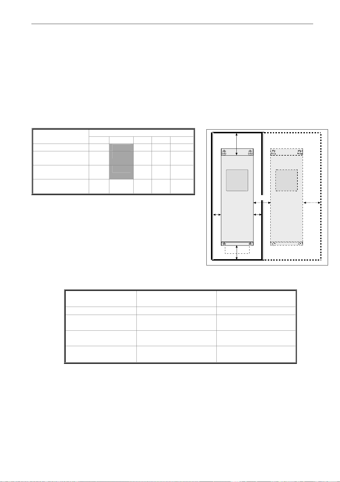
Enough free space must be left around the inverter to ensure sufficient air circulation and cooling.
You will find the required dimensions for free space in the table below.
If several units are mounted on top of each other, the required free space equals C + D (see figure
below). Moreover, the outlet air used for cooling by the lower unit must be directed away from the air
intake of the upper unit. When planning the cooling for the space, take into consideration that the
inverter’s heat loss is 2.5% of the nominal capacity.
Type Dimensions [mm] A NXI_0004—0012 5 NXI_0016—0048 5
20
30
NXI_0004—0034 6
NXI_0061—0105 5
80
NXI_0041—0052 6
NXI_01405
80 150 80 300 200
NXI_0062—0100 6
Table 5-6. Mounting space dimensions
A2
B C D
20 100 50
20 160 80
80 300 100
C
B
B
A = clearance around the inverter (see also
A
= clearance needed on either side of the inverter for fan
2
and B)
2
change (without disconneting the motor cables)
** = min. clearance for fan change
B = distance from one inverter to another or distance to cabinet
wall
C = free space above the inverter
D = free space underneath the inverter
Type Greatest possible heat loss
(kW)
NXI_0004—0012 5 0,2 NXI_0016—0048 5
NXI_0004—0034 6
NXI_0061—0105 5
NXI_0041—0052 6
NXI_01405
NXI_0062—0100 6
1
0,75
1,9
1,2
3,3
2,25
Table 5-7. Required cooling air
A
A
2
A
A
2
D
Figure 5-6. Installation space
Cooling air required [m3/h)
70
425
425
650
NK5_2
5
Page 27
26 • vacon installation
Clearwater Tech - Phone: 800.894.0412 - Fax: 208.368.0415 - Web: www.clrwtr.com - Email: [email protected]
5.2.2 Power losses as function of switching frequency
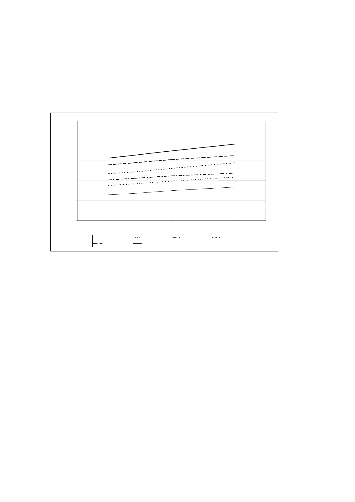
Raising the switching frequency of the drive, to reduce motor noise for example, inevitably affects
the power losses and cooling requirements as shown in the Figure below. It illustrates the power
loss FR7 as function of switching frequency. For more information, contact the Manufacturer or your
local distributor (see back cover).
2500,00
2000,00
1500,00
P[W]
1000,00
500,00
0,00
0,00 2,00 4,00 6,00 8,00 10,00 12,00
NXI_0072 5 400V NXI_0072 5 500V NXI_0087 5 400V NXI 0087 5 500V
NXI_0105 5 400V
switching frequency [kHz]
NXI_0105 5 500V
Figure 5-7. Power loss as a function of switching frequency; NXI 0061…0105 5
Tel: +358-201-2121 • Fax: +358-201-212 205
5
Page 28
cabling and connections vacon • 27
Clearwater Tech - Phone: 800.894.0412 - Fax: 208.368.0415 - Web: www.clrwtr.com - Email: [email protected]
6. CABLING AND CONNECTIONS
6.1 Power unit
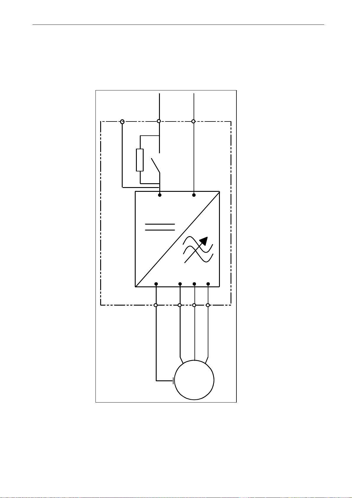
The following wiring diagrams show the supply and motor connections.
B+
DC+
B+ B-
PE
DC-
UVW
M
Figure 6-1. The basic wiring diagram
6
Page 29
28 • vacon cabling and connections
Clearwater Tech - Phone: 800.894.0412 - Fax: 208.368.0415 - Web: www.clrwtr.com - Email: [email protected]
6.1.1 Power connections
6.1.1.1 DC supply and motor cables
The power cables are connected to terminals DC+ and DC- (R+/B+ and DC terminals when using an
external charging circuit) and the motor cables to terminals U, V and W. A cable entry gland should
be used at the motor cable end to reach the EMC levels, see Table 6-1.
Use cables with a heat resistance of at least +60°C. The cables and the fuses must be sized
according to the inverter nominal output current which you can find on the rating plate. Installation
of cables according to UL regulations is presented in Chapter 6.1.3 and aR fuse sizes in Tables 6-2
and 6-3. The minimum dimensions of the Cu-cables are shown in Table 6-4.
If the motor temperature protection of the drive (see Vacon All in One Application Manual) is used as
an overload protection, the cable shall be chosen accordingly. If three or more cables are used in
parallel for bigger units, each cable requires a separate overload protection.
These instructions apply only to installations with one motor and one cable connection from the
inverter to the motor. In any other case, ask the factory for more information.
Cable type Level T
Supply cable
Motor cable
Control cable
Table 6-1. Cable types required to meet standards
Power cable intended for fixed installation and the specific DC
voltage. Shielded cable not required. (NKCABLES/MCMK or
Power cable equipped with concentric protection wire and
intended for the specific mains voltage. (NKCABLES/MCMK or
Screened cable equipped with compact low-impedance shield
similar recommended)
similar recommended).
(NKCABLES/jamak, SAB/ÖZCuY-O or similar).
6.1.1.2 Control cable
For information on control cables, see Chapter 6.2.1.1 and Table 6-1.
Tel: +358-201-2121 • Fax: +358-201-212 205
6
Page 30
cabling and connections vacon • 29
Clearwater Tech - Phone: 800.894.0412 - Fax: 208.368.0415 - Web: www.clrwtr.com - Email: [email protected]
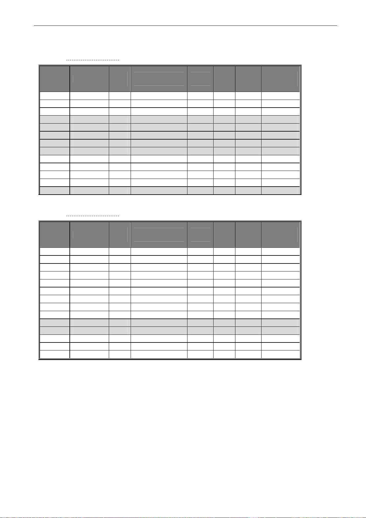
6.1.1.3 Fuses, NXI_xxxx 5
Frame Type
I
L
[A]
Bussman aR fuse
type
Fuse
size
Fuse
U
[V]
Fuse
n
In
[A]
FR4 NXI_0004 4.3 170M1560 000 690 20 2 FR4 NXI_0009 9 170M1565 000 690 63 2 FR4 NXI_0012 12 170M1565 000 690 63 2 FR6 NXI_0016 16 170M1565 000 690 63 2 FR6 NXI_0022 22 170M1565 000 690 63 2 FR6 NXI_0031 31 170M1565 000 690 63 2 FR6 NXI_0038 38 170M1567 000 690 100 2 FR6 NXI_0045 45 170M1567 000 690 100 2 FR7 NXI_0061 61 170M1568 000 690 125 2 FR7 NXI_0072 72 170M1570 000 690 200 2 FR7 NXI_0087 87 170M1570 000 690 200 2 FR7 NXI_0105 105 170M1571 000 690 250 2 FR8 NXI_0140 140 170M3819 1 690 400 2
Table 6-2. Fuses used in Vacon NX (465 - 800V)
6.1.1.4 Fuses, NXI_xxxx 6
Fuse
U
[V]
Frame Type
I
L
[A]
Bussman aR fuse
type
Fuse
size
FR6 NXI_0004 4.5 170M2673 00 1000 20 2 FR6 NXI_0005 5.5 170M2673 00 1000 20 2 FR6 NXI_0007 7.5 170M2673 00 1000 20 2 FR6 NXI_0010 10 170M2673 00 1000 20 2 FR6 NXI_0013 13.5 170M2679 00 1000 63 2 FR6 NXI_0018 18 170M2679 00 1000 63 2 FR6 NXI_0022 22 170M2679 00 1000 63 2 FR6 NXI_0027 27 170M2679 00 1000 63 2 FR6 NXI_0034 34 170M2683 00 1000 160 2 FR7 NXI_0041 41 170M2683 00 1000 160 2 FR7 NXI_0052 52 170M2683 00 1000 160 2 FR8 NXI_0062 62 170M4200 1SHT 1250 350 2 FR8 NXI_0080 80 170M4200 1SHT 1250 350 2 FR8 NXI_0100 100 170M4200 1SHT 1250 350 2
Table 6-3. Fuses used in Vacon NX (640 - 1100V)
Fuse
n
In
[A]
No. of
fuses
No. of
fuses
Information about fuses
aR fuses protect the cables of the device against short-circuits.
gR fuses are designed to protect the device against both overcurrent and short-circuits.
gG fuses are generally used to protect cables against overcurrent and short-circuits.
6
Page 31
30 • vacon cabling and connections
Clearwater Tech - Phone: 800.894.0412 - Fax: 208.368.0415 - Web: www.clrwtr.com - Email: [email protected]
6.1.1.5 Cable sizes, NXI_xxxx 5
Terminal cable size
Main terminal
[mm2]
Frame Type
I
L
[A]
Supply
cable
Cu [mm2]
Motor cable
Cu [mm2]
NXI_0004 5—0009 5 3—9 2*1.5 3*1.5+1.5 1—4 1—2.5 FR4 NXI_0012 5 12 2*2.5 3*2.5+2.5 1—4 1—2.5
FR6
FR7
NXI_0016 5—0045 5 16—45 2*10 3*10+10
NXI_0061 5 61 2*16 3*16+16
NXI_0072 5 72 2*25 3*25+16
NXI_0087 5 87 2*35 3*35+16
NXI_0105 5 105 2*50 3*50+25
2.5—50 Cu 6—50 Al
2.5—50 Cu 6—50 Al
2.5—50 Cu 6—50 Al
2.5—50 Cu 6—50 Al
2.5—50 Cu 6—50 Al
FR8 NXI_0140 5 140 2*70 3*70+35 25—95 Cu/Al 25—95
Table 6-4. Cable sizes for Vacon NX_5
6.1.1.6 Cable sizes, NXI_xxxx 6
Terminal cable size
Main terminal
[mm2]
2.5—50 Cu 6—50 Al
2.5—50 Cu 6—50 Al
2.5—50 Cu 6—50 Al
2.5—50 Cu 6—50 Al
2.5—50 Cu 6—50 Al
2.5—50 Cu 6—50 Al
2.5—50 Cu 6—50 Al
25—95 Cu/Al 25—95
Frame Type
FR6
NXI_0004 6—0007 6 3—7 2*2.5 3*2.5+2.5
NXI_0010 6—0013 6 10-13 2*2.5 3*2.5+2.5
NXI_0018 6 18 2*4 3*4+4
NXI_0022 6 22 2*6 3*6+6
NXI_0027 6–0034 6 27-34 2*10 3*10+10
FR7
NXI_0041 6 41 2*100 3*10+10
NXI_0052 6 52 2*16 3*16+16
NXI_0062—0080 6 62–80 2*25 3*25+16 FR8 NXI_0100 6 100 2*35 3*35+16
Table 6-5. Cable sizes for Vacon NX_6
I
L
[A]
Supply
cable
Cu [mm2]
Motor cable
Cu [mm2]
Earth
terminal
[mm2]
2.5—35
2.5—35
6—70
6—70
6—70
Earth
terminal
[mm2]
2.5—35
2.5—35
2.5—35
2.5—35
2.5—35
6—50
6—50
Tel: +358-201-2121 • Fax: +358-201-212 205
6
Page 32
cabling and connections vacon • 31
[m]
[m]
≤
≤
Clearwater Tech - Phone: 800.894.0412 - Fax: 208.368.0415 - Web: www.clrwtr.com - Email: [email protected]
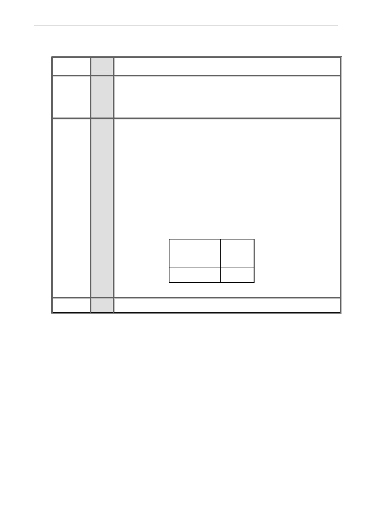
6.1.2 Installation instructions
Before starting the installation, check that none of the components of the
1
inverter are live.
If the inverter is installed outside the cubicle, cabinet or device space,
2
you need to install a separate inverter cover (see, for example Figure 6-3
) in accordance with protection class IP21 requirements. There is no
need to install the inverter cover if the inverter is installed in a cubicle,
separate cabinet or device space.
Place the motor cables sufficiently far from other cables:
3
Avoid placing the motor cables in long parallel lines with other
cables
If the motor cables runs in parallel with other cables, note the
minimum distances between the motor cables and other cables
given in the table below.
The given distances also apply between the motor cables and
signal cables of other systems.
The maximum length of the motor cables is 300 m (units with
power greater than 1.5 kW) and 100 m (units with power from 0.75
to 1.5 kW).
The motor cables should cross other cables at an angle of 90
degrees.
Distance
between cables
0.3
1.0
Shielded
cable
50
200
If cable insulation checks are needed, see Chapter 6.1.4.
4
6
Page 33
32 • vacon cabling and connections
Clearwater Tech - Phone: 800.894.0412 - Fax: 208.368.0415 - Web: www.clrwtr.com - Email: [email protected]
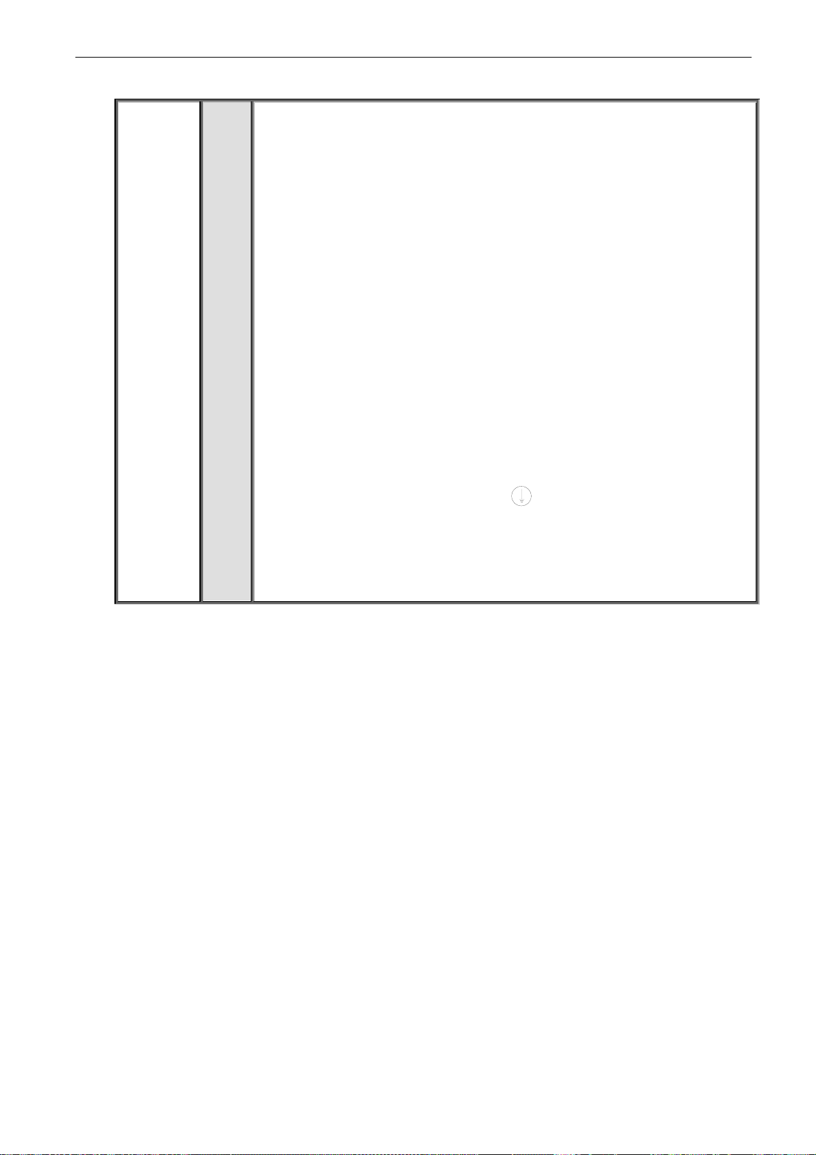
Connect the cables:
5
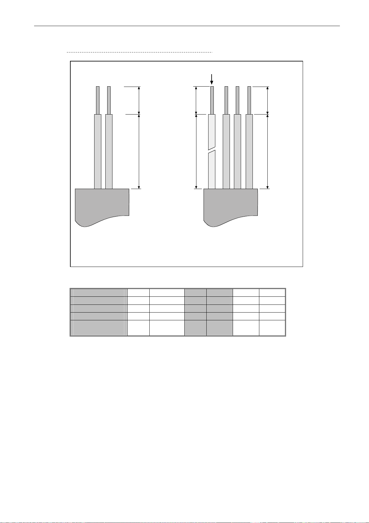
Strip the motor and DC supply cables as advised in Figure 6-2
and Table 6-6.
Remove the screws of the cable protection plate. Do not open the
cover of the power unit!
Make holes into and pass the cables through the rubber
grommets on the bottom of the power unit. The rubber grommets
are delivered in a separate bag.
Connect the DC supply, motor and control cables into their
respective terminals.
For information on the installation of greater units, please contact
the factory or your local distributor.
For Information on cable installation according to UL
regulations, see Chapter 6.1.3.
For information on cable installation according to EMC
regulations, see Chapter 6.1.3.
Make sure that the control cable wires do not come in contact with
the electronic components of the unit.
If an external brake resistor (optional) is used, connect its cable
to the appropriate terminal.
Check the connection of the earth cable to the motor and the
inverter terminals marked with
Connect the separate shield of the power cable to the earth
terminals of the inverter, motor and the supply centre.
Attach the cable protection plate with the screws. Ensure that the control cables or the cables of the unit are not
trapped between the frame and the protection plate.
.
Tel: +358-201-2121 • Fax: +358-201-212 205
6
Page 34
cabling and connections vacon • 33
Clearwater Tech - Phone: 800.894.0412 - Fax: 208.368.0415 - Web: www.clrwtr.com - Email: [email protected]
6.1.2.1 Stripping lengths of motor and DC supply cables
Earth conductor
C1
D1
DC SUPPLY MOTOR
Figure 6-2. Stripping of cables
B2
C2A2
D2
nk6141.fh8
Frame size C1 D1 A2 B2 C2 D2
FR4 10 20/70 7 50 7 35 FR6 15 60/80 20 90 15 60 FR7 25 120/140 25 120 25 120 FR8
0140
Table 6-6. Cable stripping lengths [mm]
30
150
23
240
23
240
6
Page 35

34 • vacon cabling and connections
Clearwater Tech - Phone: 800.894.0412 - Fax: 208.368.0415 - Web: www.clrwtr.com - Email: [email protected]
6.1.2.2 Vacon NX frames
Figure 6-3. Vacon NXI, FR4
Figure 6-4. Vacon NXI, FR6, protection class IP21
Tel: +358-201-2121 • Fax: +358-201-212 205
6
Page 36

cabling and connections vacon • 35
Clearwater Tech - Phone: 800.894.0412 - Fax: 208.368.0415 - Web: www.clrwtr.com - Email: [email protected]
Figure 6-5. Vacon NXI, FR7. Protection class IP21
Figure 6-6. Vacon NXI, FR8. Protection class IP00
6
Page 37
36 • vacon cabling and connections
Clearwater Tech - Phone: 800.894.0412 - Fax: 208.368.0415 - Web: www.clrwtr.com - Email: [email protected]
6.1.3 Cable installation and the UL standards
To meet the UL (Underwriters Laboratories) regulations, a UL-approved copper cable with a
minimum heat-resistance of +60/75°C must be used.
The tightening torques of the terminals are given below in Table 6-7.
Type Frame Tightening torque
[Nm]
NXI_0003 - 0012 5 FR4 0.5—0.6
NXI_0038 - 0061 5
NXI_0004 - 0034 6
NXI_0072 - 0105 5
NXI_0041 - 0080 6
NXI_0140 5
NXI_0062 – 0100 6
Table 6-7. Tightening torques of terminals
* Tightening torque of terminal connection to the isolative base in Nm.
FR6 10
FR7 10
FR8 20/9*
6.1.4 Cable and motor insulation checks
1. Motor cable insulation checks
Disconnect the motor cable from terminals U, V, and W of the inverter and from the motor.
Measure the insulation resistance of the motor cable between each phase conductor as well as
between each phase conductor and the protective ground conductor.
The insulation resistance must be >1MΩ.
2. DC supply cable insulation checks
Disconnect the DC supply cable from terminals B- and B+ of the inverter and from DC supply.
Measure the insulation resistance between each conductor and ground.
The insulation resistance must be >1MΩ.
3. Motor insulation checks
Disconnect the motor cable from the motor and open the bridging connections in the motor
connection box. Measure the insulation resistance of each motor winding. The measurement
voltage must equal at least the motor nominal voltage but not exceed 1,000 V.
The insulation resistance must be >1MΩ.
Tel: +358-201-2121 • Fax: +358-201-212 205
6
Page 38
cabling and connections vacon • 37
Clearwater Tech - Phone: 800.894.0412 - Fax: 208.368.0415 - Web: www.clrwtr.com - Email: [email protected]
6.2 Control unit
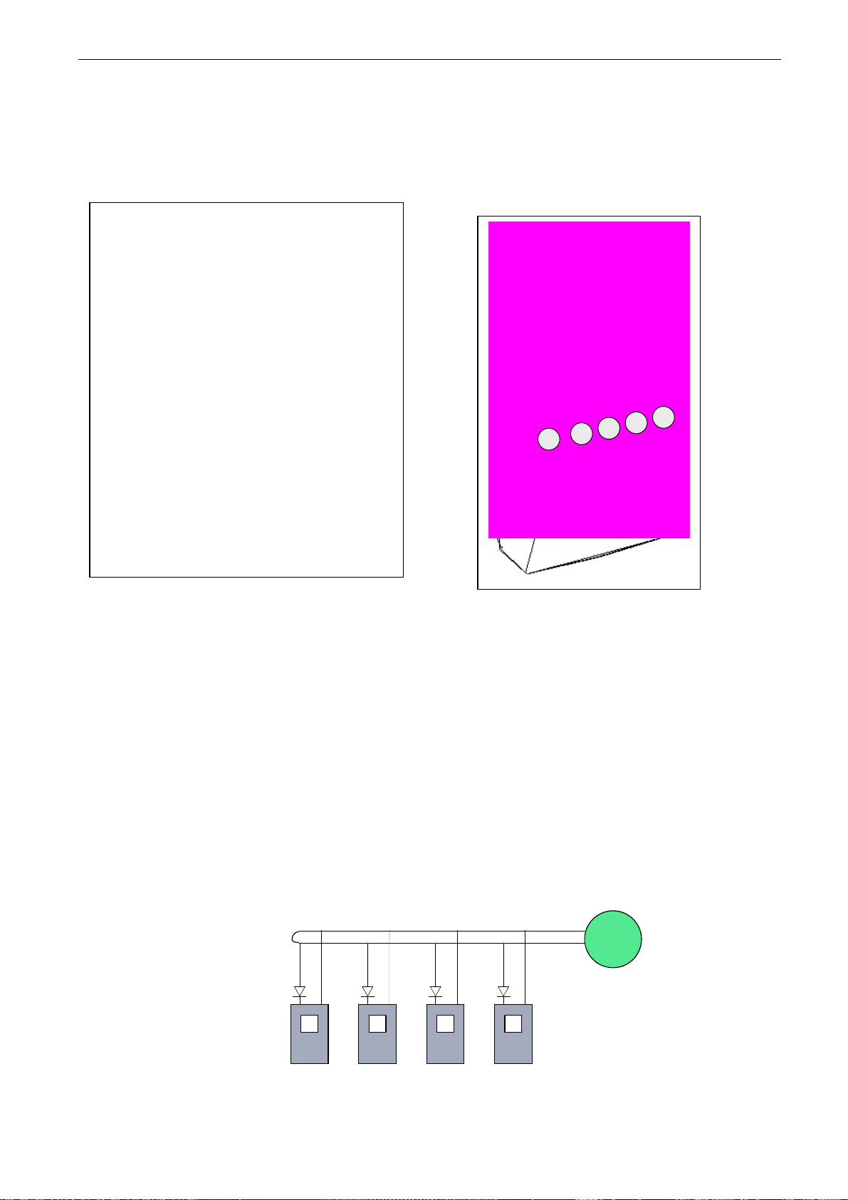
The control unit of the inverter consists of the control board and option boards (see Figure 6-7 and
Figure 6-20) connected to the five slot connectors (A to E) on the control board. The control board is
connected to the power unit through a D connector (1).
E
D
C
B
A
Figure 6-7. control board Figure 6-8. Basic and option board connections
on the control board
When the inverter is delivered from the factory, the control unit usually includes two basic boards
(I/O board and relay board), which are normally installed in slots A and B. On the next pages you will
find the arrangement of the control I/O and the relay terminals of the two basic boards, the general
wiring diagram and the control signal descriptions. The I/O boards mounted at the factory are
indicated in the type code. For more information on the option boards, see Vacon NX option board
manual (ud741).
The control board can be powered externally (+24V) by connecting the external power source to
bidirectional terminal #6 (see Table 6-9). This voltage is sufficient for parameter setting and for
keeping the fieldbus active.
Note! If the +24V input of several inverters are connected in parallel, we recommend to use a diode
in terminal #6 to avoid the current to flow in opposite direction, which might damage the control
board.
+ -
# 6 # 7
+ -
#6 #7
+ -
#6 #7
+ -
#6 #7
External
+ 2 4 V
nk6_17
6
Page 39
38 • vacon cabling and connections
Clearwater Tech - Phone: 800.894.0412 - Fax: 208.368.0415 - Web: www.clrwtr.com - Email: [email protected]
6.2.1 Control connections
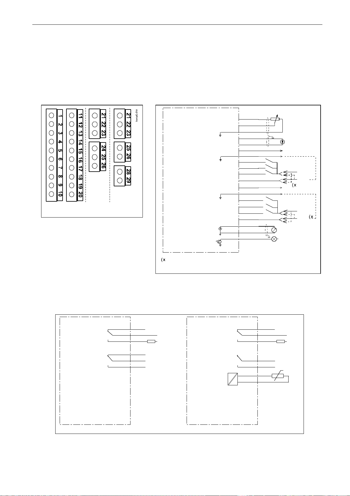
The basic control connections for boards A1 and A2/A3 are shown in Chapter 6.2.2.
The signal descriptions for the standard application are presented in Chapter 2 of the All in One
Application Manual. You can find the signal descriptions for other applications in the Vacon NX
Application Manual.
+10Vref
OPT-A2 OPT-A3
Board OPT-A1
in slot A
Boards OPT-A2 and
OPT-A3 in slot B
Figure 6-9. The I/O terminals
of the two basic boards
Basic I/O board
NXOPTA1
1
2
3
4
5
6
7
8
9
10
11
12
13
14
15
16
17
18
19
20
AIA1+
GND
AIA2+
AIA224Vout
GND
DIA1
DIA2
DIA3
CMA
24Vout
GND
DIB4
DIB5
DIB6
CMB
Iout+
Iout-
DO1
Reference
(voltage)
Reference
(current)
0(4)/20mA
RL<500
U<+48V
+
I<50mA
Ω
24 V
GND
24 V
GND
Dotted line indicates the connection with
inverted signal levels
Figure 6-10. General wiring diagram of the basic I/O board
(NXOPTA1)
Switching:
<8 A / 2 4 V d c ,
<0 . 4 A / 1 2 5 V d c ,
<2 k V A / 2 5 0 V a c
Continuously:
<2 A r m s
Basic relay board
OPT-A3
21
22
23
25
26
28
29
RO1/1
1/2
RO1/3
2/1
RO2/2
TI1+
TI1-
+t
Basic relay board
OPT-A2
NX6_6.fh8
21
22
23
24
25
26
RO1/1
1/2
RO1/3
RO2/1
2/2
RO2/3
ac/dc
Switching:
<8 A / 2 4 V d c ,
<0.4A/125Vdc,
<2 k V A / 2 5 0 V a c
Continuously:
<2Arms
Figure 6-11. General wiring diagram of the basic relay boards (NXOPTA2/NXOPTA3)
ac/dc
Page 40
cabling and connections vacon • 39
Clearwater Tech - Phone: 800.894.0412 - Fax: 208.368.0415 - Web: www.clrwtr.com - Email: [email protected]
6.2.1.1 Control cables
The control cables shall be at least 0.5 mm2 screened multicore cables, see Table 6-8. The
maximum terminal wire size is 2.5 mm
2
for the relay terminals and 1.5 mm2 for other terminals.
You can find the tightening torques of the option board terminals below.
Terminal screw
Tightening torque
Nm lb-in.
Relay and
thermistor
terminals
0.5 4.5
(screw M3)
Other terminals
(screw M2.6)
0.2 1.8
Table 6-8. Tightening torques of terminals
6.2.1.2 Galvanic isolation barriers
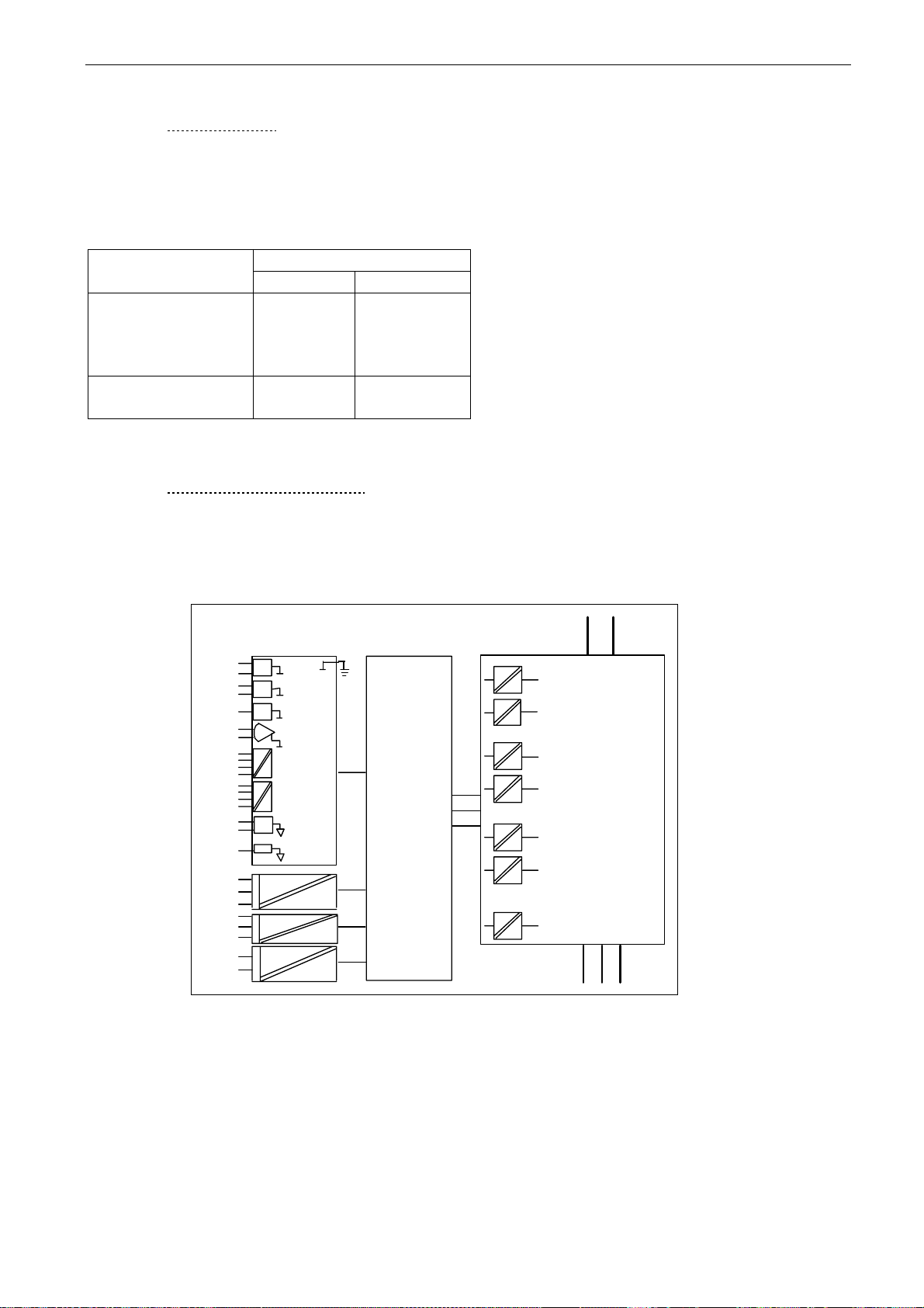
The control connections are isolated from the mains potential and the GND terminals are
permanently connected to ground. See below.
The digital inputs are galvanically isolated from the I/O ground. The relay outputs are additionally
double-isolated from each other at 300VAC (EN-50178).
10Vref
GN D
+24V
GN D
AI1
AI2+
AI2 DIN1...
DIN3
CM A
DIN4...
DIN6
CM B
AO1+
AO2 -
DO1
RO1/1
RO1/2
RO1/3
RO2/1
RO2/2
RO2/3
TI1+
TI1-
Control I/O
ground
Digital input
group A
Digital input
group B
Analogue
output
Digital
output
Control
panel
Control
board
Figure 6-12. Galvanic isolation barriers
Gat e dr ivers
nk6_15
DC+ DC-
Power
board
U V W
6
Page 41
40 • vacon cabling and connections
Clearwater Tech - Phone: 800.894.0412 - Fax: 208.368.0415 - Web: www.clrwtr.com - Email: [email protected]
6.2.2 Control terminal signals
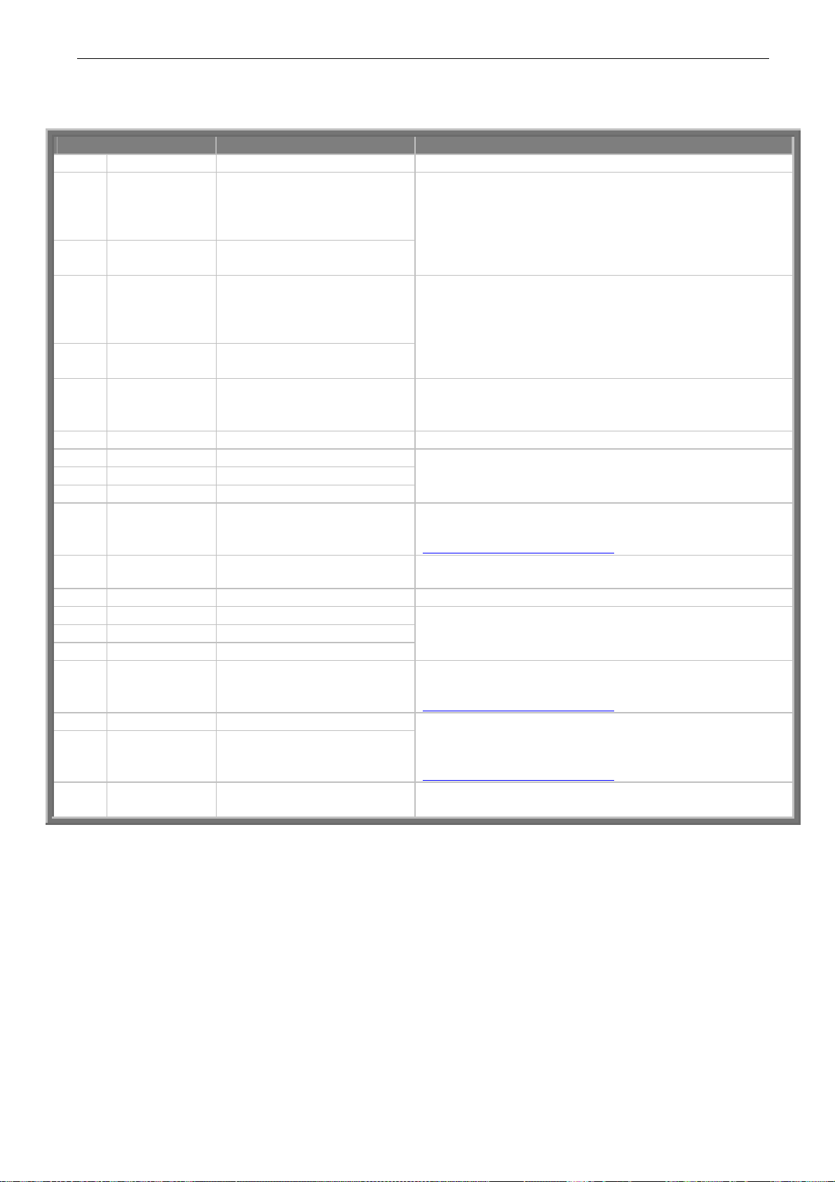
Terminal Signal Technical information
1 +10 Vref Reference voltage Maximum current 10 mA 2 AI1+ Analogue input,
voltage or current
3 GND/AI1– Analogue input common Differential input if not connected to ground;
4 AI2+ Analogue input,
voltage or current
5 GND/AI2– Analogue input common Differential input if not connected to ground;
6 24 Vout
(bidirectional)
24V auxiliary voltage
7 GND I/O ground Ground for reference and controls 8 DIN1 Digital input 1 9 DIN2 Digital input 2
10 DIN3 Digital input 3 11 CMA Digital input common A for
DIN1, DIN2 and DIN3.
12 24 Vout
(bidirectional)
24V auxiliary voltage Same as terminal #6
13 GND I/O ground Same as terminal #7 14 DIN4 Digital input 4 15 DIN5 Digital input 5 16 DIN6 Digital input 6 17 CMB Digital input common B for
DIN4, DIN5 and DIN6
18 AO1+ Analogue signal (+output) 19 AO1– Analogue output common
20 DO1 Open collector output Maximum Uin = 48VDC
Selection V or mA with jumper block X1 (see page 43):
Default: 0– +10V (Ri = 200 kΩ)
(-10V…..+10V Joy-stick control, selected with a jumper)
0– 20mA (Ri = 250 Ω)
Allows ±20V differential mode voltage to GND
Selection V or mA with jumper block X1 (see page 43):
Default: 0– 20mA (Ri = 250 Ω)
0– +10V (Ri = 200 kΩ)
(-10V…..+10V Joy-stick control, selected with a jumper)
Allows ±20V differential mode voltage to GND
±15%; maximum current 250 mA all boards total; 150 mA
from single board. Can also be used as external power
backup for the control unit (and fieldbus).
= min. 5kΩ
R
i
18…30V = "1"
Must be connected to GND or 24V of I/O terminal or
to external 24V or GND
Selection with jumper block X3
= min. 5kΩ
R
i
(see page 43):
18…30V = "1"
Must be connected to GND or 24V of I/O terminal or
to external 24V or GND
Selection with jumper block X3
(see page 43):
Output signal range:
Current 0(4)–20mA, R
Voltage 0—10V, R
Selection with jumper block X3
max. 500Ω or
L
>1kΩ
L
(see page 43):
Maximum current = 50 mA
Table 6-9. Control I/O terminal signals on basic I/O board NXOPTA1
Tel: +358-201-2121 • Fax: +358-201-212 205
6
Page 42
cabling and connections vacon • 41
Clearwater Tech - Phone: 800.894.0412 - Fax: 208.368.0415 - Web: www.clrwtr.com - Email: [email protected]
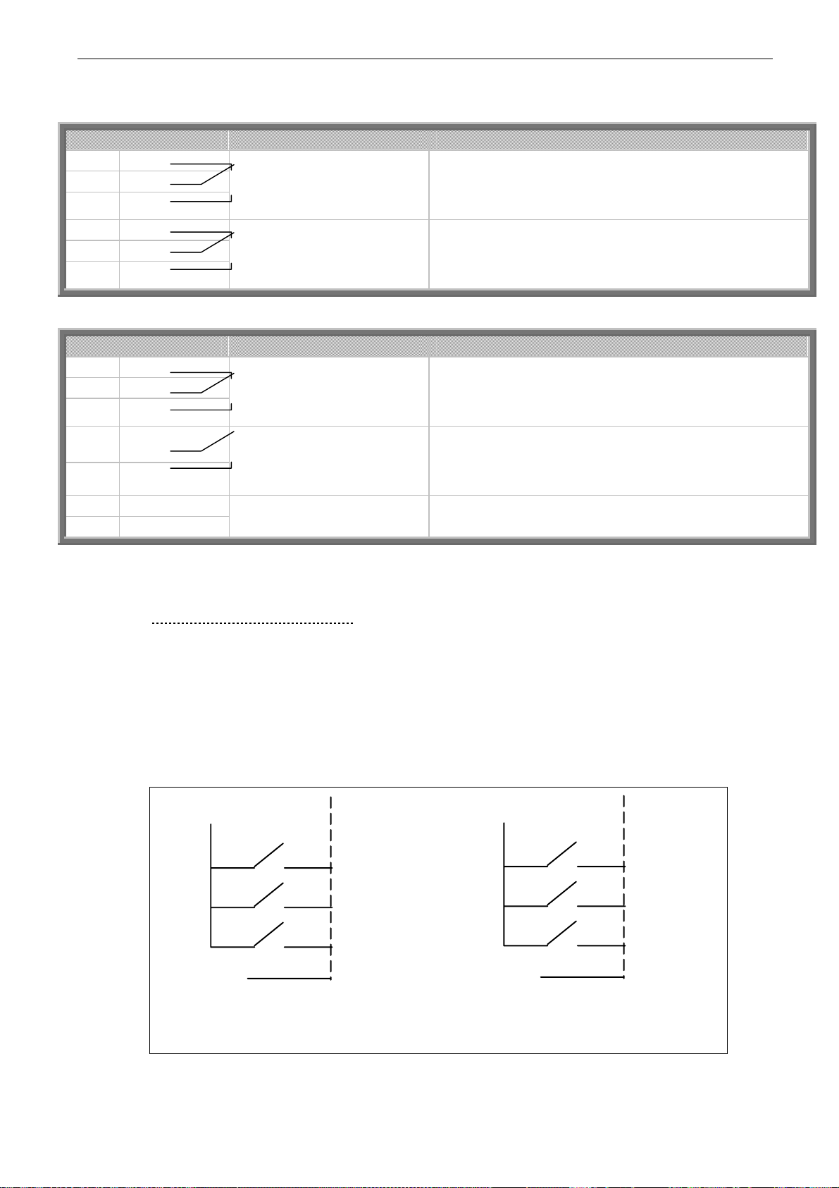
NXOPTA2
21 RO1/1 22 RO1/2 23 RO1/3
24 RO2/1 25 RO2/2 26 RO2/3
Relay output 1 Switching capacity 24VDC/8A
250VAC/8A 125VDC/0.4A Min.switching load 5V/10mA
Relay output 2 Switching capacity 24VDC/8A
250VAC/8A 125VDC/0.4A
Min.switching load 5V/10mA
Table 6-10. Control I/O terminal signals on basic relay board NXOPTA2
NXOPTA3
21 RO1/1 22 RO1/2 23 RO1/3
25 RO2/1
26 RO2/2
28 TI1+ 29 TI1–
Relay output 1 Switching capacity 24VDC/8A
250VAC/8A 125VDC/0.4A Min.switching load 5V/10mA
Relay output 2
Thermistor input
Switching capacity 24VDC/8A
250VAC/8A 125VDC/0.4A
Min.switching load 5V/10mA
Table 6-11. Control I/O terminal signals on basic relay board NXOPTA3
6.2.2.1 Digital input signal inversions
The active signal level depends on which potential the common inputs CMA and CMB (terminals 11
and 17) are connected to. The alternatives are either +24V or ground (0 V). See Figure 6-13.
We recommend the use of positive logic in all control connections of the inverter. If negative logic is
used, additional appropriate measures are needed to meet the safety regulation requirements.
The 24 volt control voltage and the ground for the digital inputs and the common inputs (CMA, CMB)
can be either internal or external.
+24V
DIN1
DIN2
DIN3
Ground
DIN1
DIN2
DIN3
Ground
nk6 _16
Positive logic (+24V is the active signal) =
the input is active when the sw it ch is closed
CMA
+24V
Negative log ic (0V is the active signa l) =
the input is active when the switch is closed.
Requires sett ing of jumper X3 to position
‘CMA/CMB isolated from ground’
CMA
Figure 6-13. Positive/Negative logic
6
Page 43

42 • vacon cabling and connections
Clearwater Tech - Phone: 800.894.0412 - Fax: 208.368.0415 - Web: www.clrwtr.com - Email: [email protected]
6.2.2.2 Jumper selections on the NXOPTA1 basic board
The user can customise the functions of the inverter to better suit his needs by selecting certain
positions for the jumpers on the NXOPTA1 board. The positions of the jumpers determine the signal
type of analogue and digital inputs.
On the A1 basic board, there are four jumper blocks (X1, X2, X3 and X6) each containing eight pins
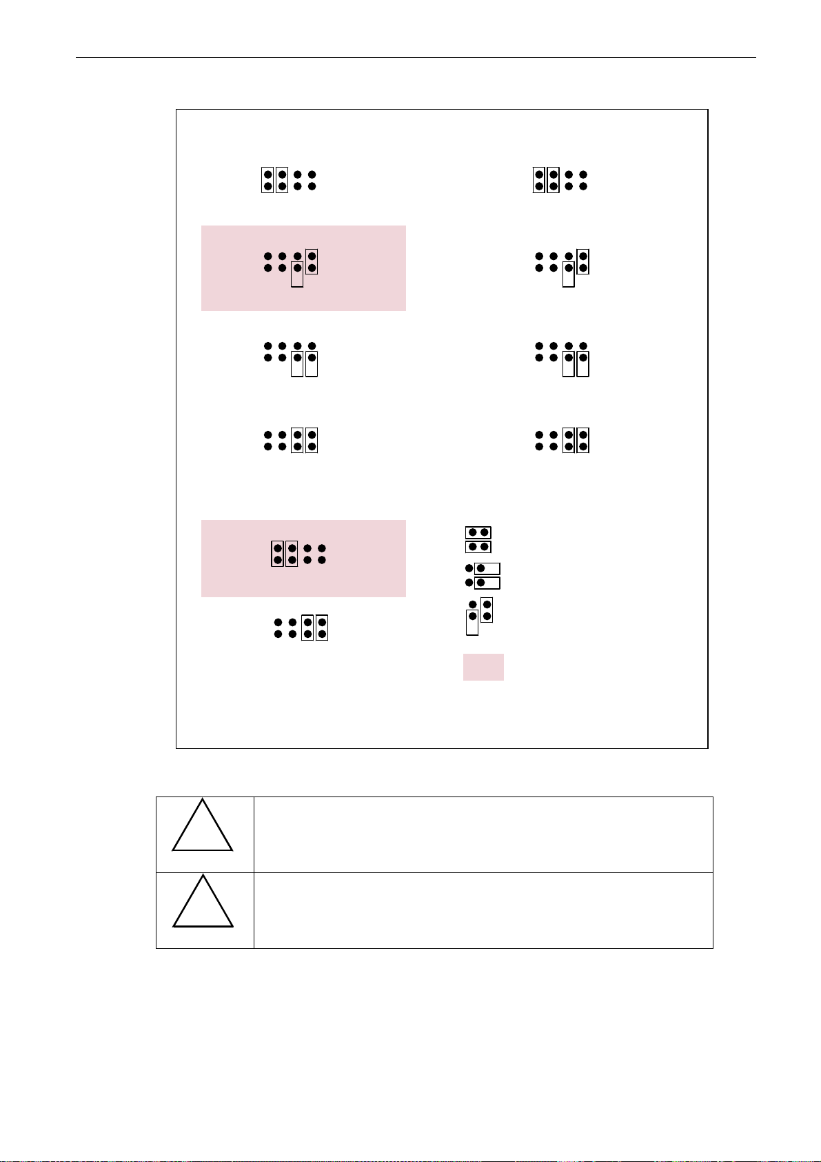
and two jumpers. The selection possibilities of the jumpers are shown on page 43 (Figure 6-15).
Figure 6-14. Jumper blocks on NXOPTA1
Tel: +358-201-2121 • Fax: +358-201-212 205
6
Page 44
cabling and connections vacon • 43
Clearwater Tech - Phone: 800.894.0412 - Fax: 208.368.0415 - Web: www.clrwtr.com - Email: [email protected]
Jumper block X1:
AI1 mode
A B C D
AI1 mode: 0...20mA; Current input
A B C D
AI1 mode: Voltage input; 0...10V
A B C D
AI1 mode: Voltage input; 0...10V (differential)
A B C D
AI1 mode: Voltage input; -10...10V
Jumper block X6:
AO1 mode
A B C D
AO1 mode: 0...20mA; Current output
A B C D
Jumper block X2:
AI2 mode
A B C D
AI2 mode : 0...20mA; Current input
A B C D
AI2 mode: Voltage input; 0...10V
A B C D
AI2 mode: Voltage input; 0...10V (differential)
A B C D
AI2 mode: Voltage input; -10...10V
Jumper block X3:
CMA and CMB grounding
CMB connected to GND
CMA connected to GND
CMB isolated from GND
CMA isolated from GND
CMB and CMA
internally connected together,
isolated from GND
AO1 mode: Voltage output; 0...10V
= Factory default
Figure 6-15. Jumper selection for NXOPTA1
!
VAROITUS
Ensure that the jumper positions are correct. Running the
motor with signal settings that differ from the jumper positions
will not harm the inverter but may harm the motor.
Note: If you change the AI/AO signal content also remember to
!
changer the corresponding board parameter in menu M7.
HUOM!
6
Page 45
44 • vacon control keypad
Clearwater Tech - Phone: 800.894.0412 - Fax: 208.368.0415 - Web: www.clrwtr.com - Email: [email protected]
7. CONTROL KEYPAD
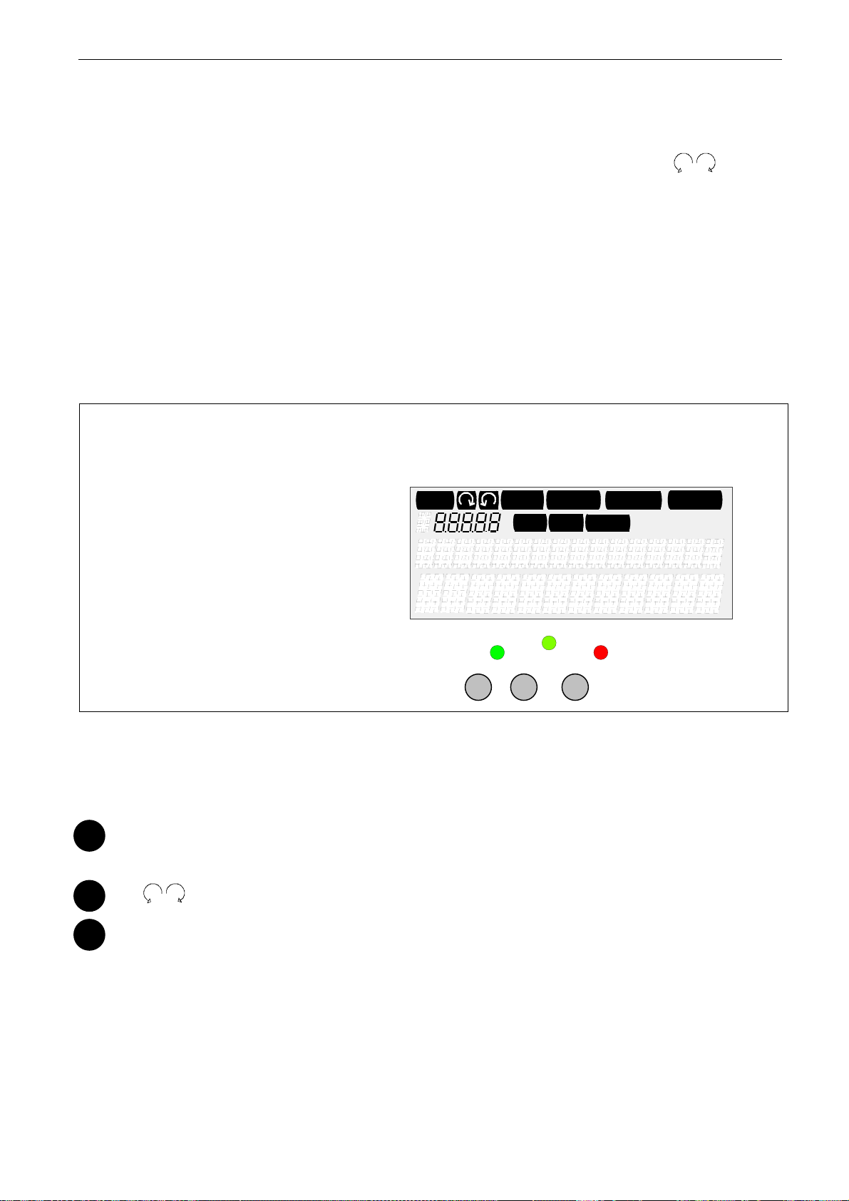
The control keypad is the link between the Vacon inverter and the user. The Vacon NX control keypad
features an alphanumeric display with seven indicators for the Run status (RUN,
, READY,
STOP, ALARM, FAULT) and three indicators for the control place (I/O term/ Keypad/BusComm).
There are also three Status Indicator LEDs (green – green – red), see section 7.1.3.
The control information, i.e. the menu number, description of the menu or the displayed value and
the numeric information are presented on three text lines.
The inverter is operable through the nine push-buttons of the control keypad. Furthermore, the
buttons can be used in setting parameters and monitoring values.
The keypad is detachable and isolated from the input line potential.
7.1 Indicators on the keypad display
RUN
I/O term
READY
Keypad
ALARM
Bus/Comm
FAULTSTOP
run
II III
Figure 7-1. Vacon control keypad and drive status indications
7.1.1 Drive status indications
Picture of control keypad
ready fault
I
The drive status symbols tell the user the status of the motor and the inverter. In addition, they tell
about possible irregularities detected by the motor control software in motor or inverter functions.
1
RUN = Motor is running; Blinks when the stop command has been given but the
frequency is still ramping down.
2
3
STOP = Indicates that the drive is not running.
= Indicates the direction of motor rotation.
Tel: +358-201-2121 • Fax: +358-201-212 205
7
Page 46

control keypad vacon • 45
Clearwater Tech - Phone: 800.894.0412 - Fax: 208.368.0415 - Web: www.clrwtr.com - Email: [email protected]
4
5
6
7.1.2 Control place indicators
The symbols
made in the Keypad control menu (M3) (see Chapter 7.3.3).
a
b
c
7.1.3 Status LEDs (green – green – red)
READY = Lights up when AC power is on. In case of a trip, the symbol will not light up.
ALARM = Indicates that the drive is running outside a certain limit and a warning is given.
FAULT = Indicates that unsafe operating conditions were encountered due to which the
drive was stopped.
Picture of control keypad
I/O term, Keypad
I/O term
Keypad
= Control keypad is selected as the control place i.e. the motor can be
Bus/Comm
= I/O terminals are selected as the control place i.e. START/STOP
= The inverter is controlled through a fieldbus.
and
Bus/Comm
commands or reference values etc. are given through the I/O terminals.
started or stopped, or its reference values etc. altered from the keypad.
(see Figure 7-1) indicate the choice of control place
Picture of control panel
The status LEDs light up in connection with the READY, RUN and FAULT drive status indicators.
I
II
III
= lights up with the AC power connected to the drive. Simultaneously, the drive
status indicator READY is lit up.
= Lights up when the drive is running. Blinks when the STOP button has been
pushed and the drive is ramping down.
= Lights up when unsafe operating conditions were encountered due to which
the drive was stopped (Fault Trip). Simultaneously, the drive status indicator
FAULT blinks on the display and the fault description can be seen, see
Chapter 7.3.3.4, Active faults.
7
Page 47

46 • vacon control keypad
Clearwater Tech - Phone: 800.894.0412 - Fax: 208.368.0415 - Web: www.clrwtr.com - Email: [email protected]
7.1.4 Text lines
The three text lines (•, ••, •••) provide the users with information on their present location in the
keypad menu structure as well as with information related to the operation of the drive.
Picture of the control panel
• = Location indicator; displays the symbol and number of the menu, parameter,
etc.
Example: M2 = Menu 2 (Parameters); P2.1.3 = Acceleration time
•• = Description line; Displays the description of the menu, value or fault.
••• = Value line; Displays the numerical and textual values of references,
parameters, etc. and the number of submenus available in each menu.
Tel: +358-201-2121 • Fax: +358-201-212 205
7
Page 48
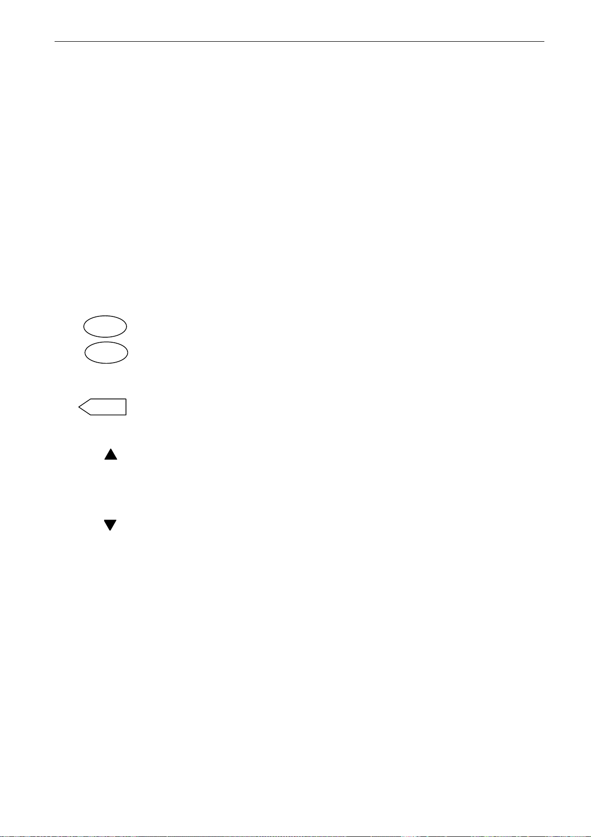
control keypad vacon • 47
Clearwater Tech - Phone: 800.894.0412 - Fax: 208.368.0415 - Web: www.clrwtr.com - Email: [email protected]
7.2 Keypad push-buttons
The Vacon alphanumeric control keypad has 9 push-buttons that are used for controlling the
inverter (and motor), setting parameters, and monitoring values.
Figure 7-1 Keypad push-buttons
7.2.1 Button descriptions
reset = This button is used to reset active faults (see Chapter 7.3.3.4).
select = This button is used to switch between the two latest displays. This may be
useful when you want to see how the changed new value influences some
other value.
enter = The enter button is used for:
1) confirmation of selections
2) fault history reset (2…3 seconds)
= Browser button up
+
Browse the main menu and the pages of different submenus. Edit values.
= Browser button down
-
Browse the main menu and the pages of different submenus. Edit values.
= Menu button left Move backward in menu. Move cursor left (in parameter menu). Exit edit mode. Press for 2 to 3 seconds to return to main menu.
7
Page 49
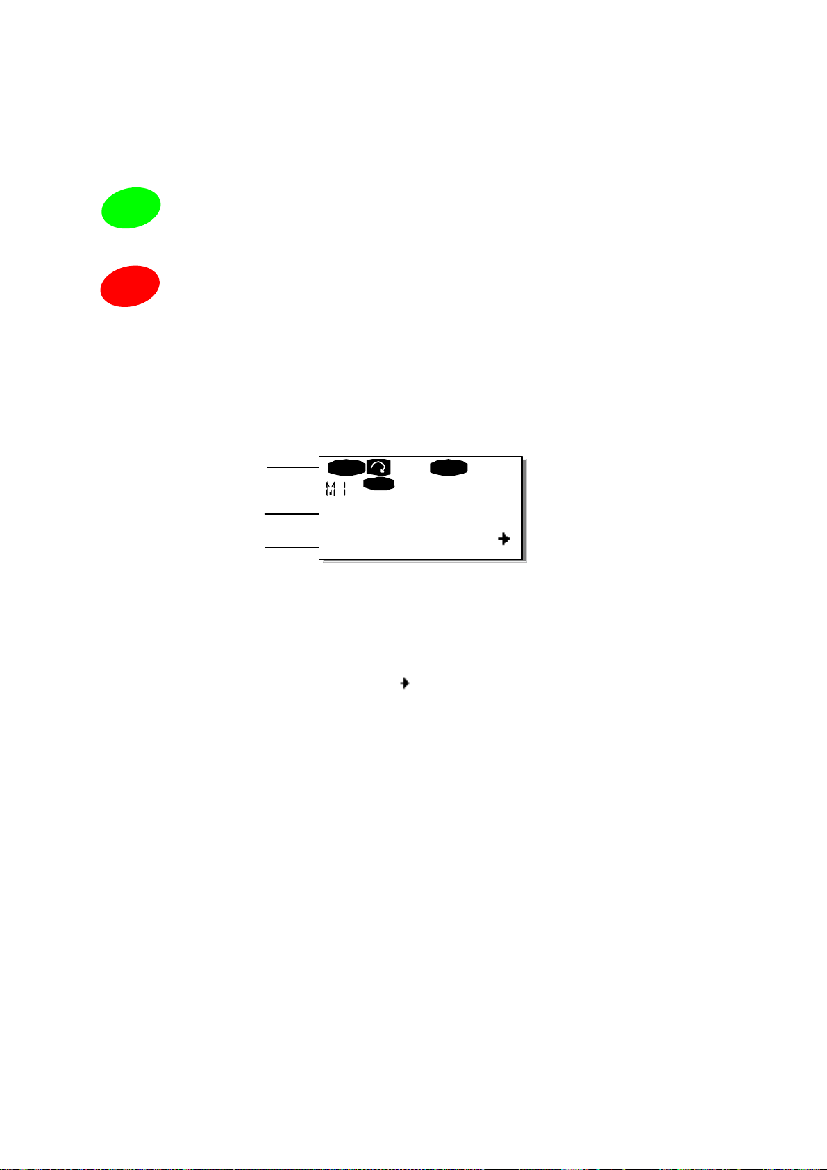
48 • vacon control keypad
Clearwater Tech - Phone: 800.894.0412 - Fax: 208.368.0415 - Web: www.clrwtr.com - Email: [email protected]
= Menu button right
4
Move forward in menu. Move cursor right (in parameter menu). Enter edit mode.
= Start button
start
Pressing this button starts the motor if the keypad is the active control
place. See Chapter 7.3.3.
= Stop button
stop
Pressing this button stops the motor (unless disabled by parameter
R3.4/R3.6). See Chapter 7.3.3.
7.3 Navigation on the control keypad
The data on the control keypad is arranged in menus and submenus. The menus are used for the
display and editing of measurement and control signals, parameter settings (see Chapter 7.3.2) and
reference value and fault displays (see Chapter 7.3.3.4). Through the menus, you can also adjust the
contrast of the display (see Chapter 7.3.6.6).
Location
Description
Number of items
available
The first menu level consists of menus M1 to M7 and is called the
in the main menu with the
the main menu with the
displayed menu or page, you can see an arrow (
reach the next menu level by pressing
The control keypad navigation chart is shown on the next page. Please note that menu
in the lower left corner. From there you will be able to navigate your way up to the desired menu
using the menu and browser buttons.
You will find more detailed descriptions of the menus later in this chapter.
Browser buttons
Menu buttons
RUN
Local
Monitor
V1V14
up and down. The desired submenu can be entered from
. When there still are pages to enter under the currently
Menu button right
READY
Main menu
) in the lower right corner of the display and can
.
. The user can navigate
M1
is located
Tel: +358-201-2121 • Fax: +358-201-212 205
7
Page 50
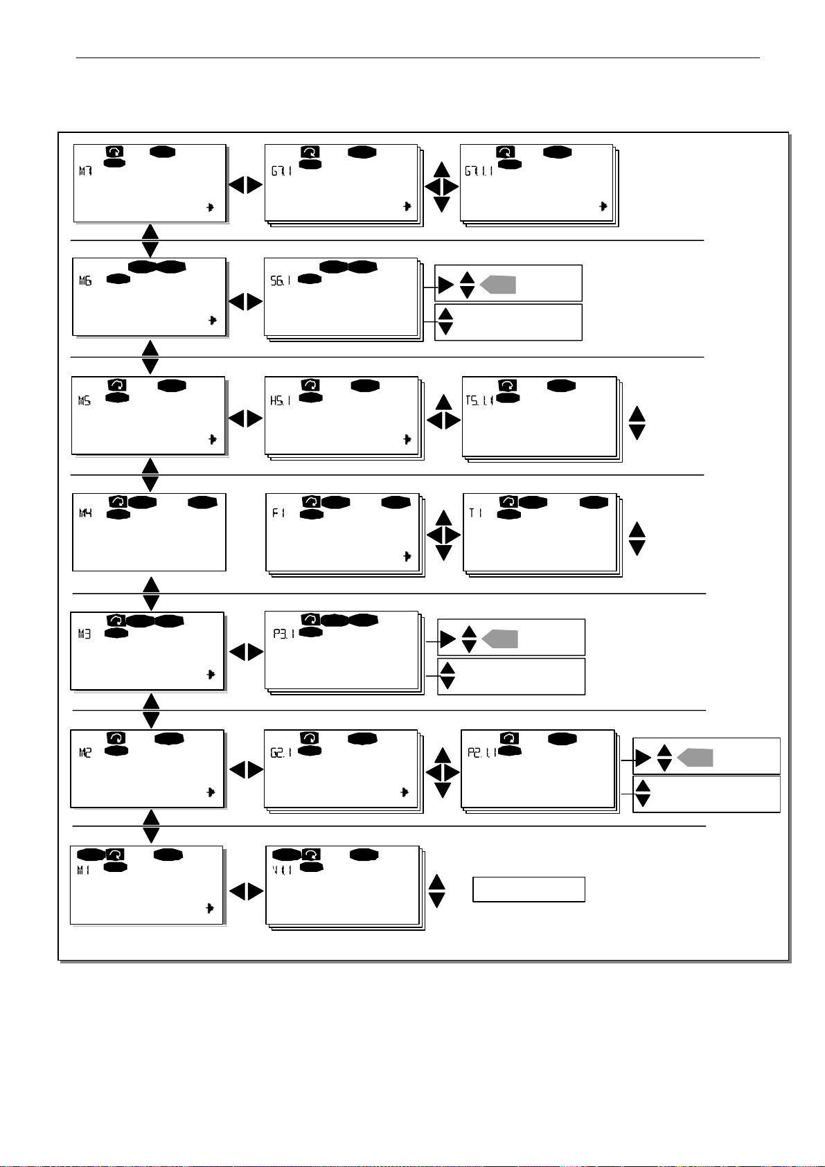
control keypad vacon • 49
Clearwater Tech - Phone: 800.894.0412 - Fax: 208.368.0415 - Web: www.clrwtr.com - Email: [email protected]
I/Oterm
Expander boards
READ Y
I/Oterm
A:NXOPTA1
G1G5
STOP READY
I/Oterm
Syste m Menu Langua ge
S1S9
READY
I/Oterm
I/Oterm
English
I/Oterm
READY
G1G1
STOP READY
READY
I/Oterm
Parameters
P1P3
Change
enter
value
Browse
I/O t erm
READY
READY
Fault history 11 Output phas e Ope rati o n days
H1
I/Oterm
H3
STOP FAULT
Active faults
F0
or:
11 Output phase Operation days
F T1
T1T7
STOP FAULT
I/Oterm
T7
17
STOP
I/Oterm
17
FAULT
READY
STOP
I/Oterm
Keypad control
P1P3
I/Oterm
READY
I/Oterm
Control Place
I/O Term in al
I/Oterm
STOP
READY
READY
enter
Browse
Local
Change
value
READY
Para me te rs Bas ic para me ter s Min Fre quen cy
G1G9
RUN
I/Oterm
Monito r Output frequency
READY
V1V15
Figure 7-2 Keypad navigation chart
RUN
I/Oterm
P1
P15
READY
13.95 Hz
1 3.95 Hz
No ed iting!
enter
Browse
Change
value
7
Page 51
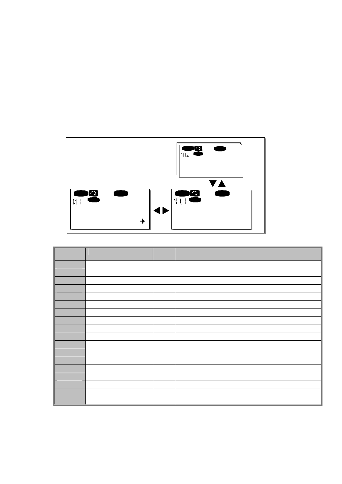
50 • vacon control keypad
V
Clearwater Tech - Phone: 800.894.0412 - Fax: 208.368.0415 - Web: www.clrwtr.com - Email: [email protected]
7.3.1 Monitoring menu (M1)
You can enter the Monitoring menu from the Main menu by pressing
Menu button right
when the
location indication M1 is visible on the first line of the display. Figure 3-1 shows how to browse
through the monitored values.
The monitored signals carry the indication V#.# and they are listed in Table 7-1. The values are
updated once every 0.3 seconds.
This menu is meant only for signal checking. The values cannot be altered here. For changing values
of parameters, see Chapter 7.3.2.
RUN
Local
READY
FreqReference
13.95 Hz
RUN RUN
Local
READY
Local
READY
Monitor Output frequency
V1V14
13.95 Hz
Figure 7-3 Monitoring menu
Code Signal name Unit Description
V1.1
V1.2
V1.3
V1.4
V1.5
V1.6
V1.7
V1.8
V1.9
V1.10
V1.11
V1.12
V1.13
V1.14
1.15
V1.16
M1.17 Multimonitoring items
Output frequency
Frequency reference
Motor speed
Motor current
Motor torque
Motor power
Motor voltage
DC-link voltage
Unit temperature
Motor temperature
Voltage input
Current input
DIN1, DIN2, DIN3
DIN4, DIN5, DIN6
DO1, RO1, RO2
Analogue output mA AO1
Hz Frequency to the motor Hz rpm Calculated motor speed A Measured motor current % Calculated actual torque/nominal torque of the unit % Calculated actual power/nominal power of the unit V Calculated motor voltage V Measured DC-link voltage ºC Heat sink temperature % Calculated motor temperature V AI1 mA AI2 Digital input statuses Digital input statuses Digital and relay output statuses
Displays three selectable monitoring values. See
chapter 7.3.6.5.
Table 7-1. Monitored signals
Note! All in One applications may embody more monitoring values.
Tel: +358-201-2121 • Fax: +358-201-212 205
7
Page 52

control keypad vacon • 51
Clearwater Tech - Phone: 800.894.0412 - Fax: 208.368.0415 - Web: www.clrwtr.com - Email: [email protected]
7.3.2 Parameter menu (M2)
Parameters are the way of conveying the commands of the user to the inverter. Parameter values
can be edited by entering the
is visible on the first line of the display. The value editing procedure is presented in Figure 7-1.
Pressing
parameter group by using the Browser buttons and press
and its parameters. Use the
Menu button right
You can now change the value in two different ways:
Set the desired value with the
Press
The value will not change unless the Enter button is pressed. Pressing
you back to the previous menu.
Several parameters are locked, i.e. cannot be edited, when the drive is in RUN status. If you try to
change the value of such a parameter the text
must be stopped to edit these parameters.
The parameter values can also be locked using the function in menu M6 (see Chapter6.5.2)).
You can return to the Main menu any time by pressing
The basic application package "All in One+" includes seven applications with different sets of
parameters. You will find the parameter lists in the Application Section of this manual.
Once in the last parameter of a parameter group, you can move directly to the first parameter of that
group by pressing
See the diagram for parameter value change procedure on page 52.
Note: You can connect power to the control board by connecting the external power source to the
bidirectional terminal #6 on the NXOPTA1 board (see page 40). The external power source can also
be connected to the corresponding +24V terminal on any option board. This voltage is sufficient for
parameter setting and for keeping the fieldbus active.
Menu button right
takes you to the edit mode. As a sign of this, the parameter value starts to blink.
Consequently, the blinking stops and the new value is visible in the value field.
Menu button right
come in handy, when a relatively greater or smaller value than that on the display is desired.
Confirm the change with the
Browser button up
Parameter Menu
once takes you to the Parameter Group Menu
Browser buttons
Browser buttons
once more. Now you will be able to edit the value digit by digit. This may
enter
button.
.
from the
to find the parameter (P#) you want to edit. Pressing
*Locked*
Main Menu
Menu button right
and confirm the change with the
when the location indication M2
(G#)
. Locate the desired
again to see the group
enter
Menu button left
will appear on the display. The inverter
Menu button left
for 1 to 2 seconds.
button.
takes
7
Page 53
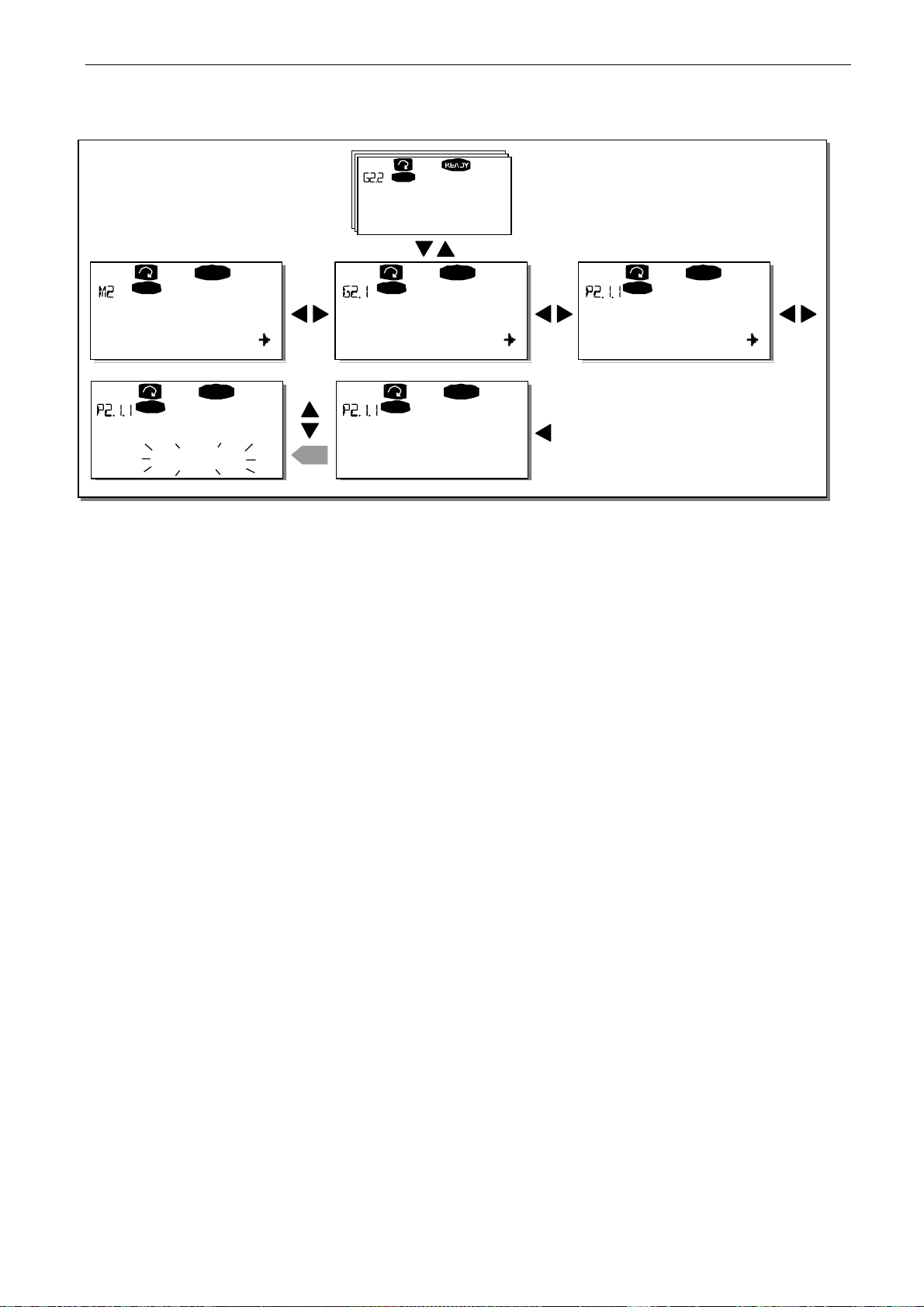
52 • vacon control keypad
Clearwater Tech - Phone: 800.894.0412 - Fax: 208.368.0415 - Web: www.clrwtr.com - Email: [email protected]
Keypad
Input signals
G1G8
Keypad
READY
Keypad
READY
Keypad
READY
Parameters Basic parameters Min Frequency
G1G8
Keypad
P1
READY
Keypad
P18
READY
13.95 Hz
Min Frequency Min Frequency
13.95 Hz
Figure 7-1. Parameter value change procedure
enter
14.45 Hz
Tel: +358-201-2121 • Fax: +358-201-212 205
7
Page 54
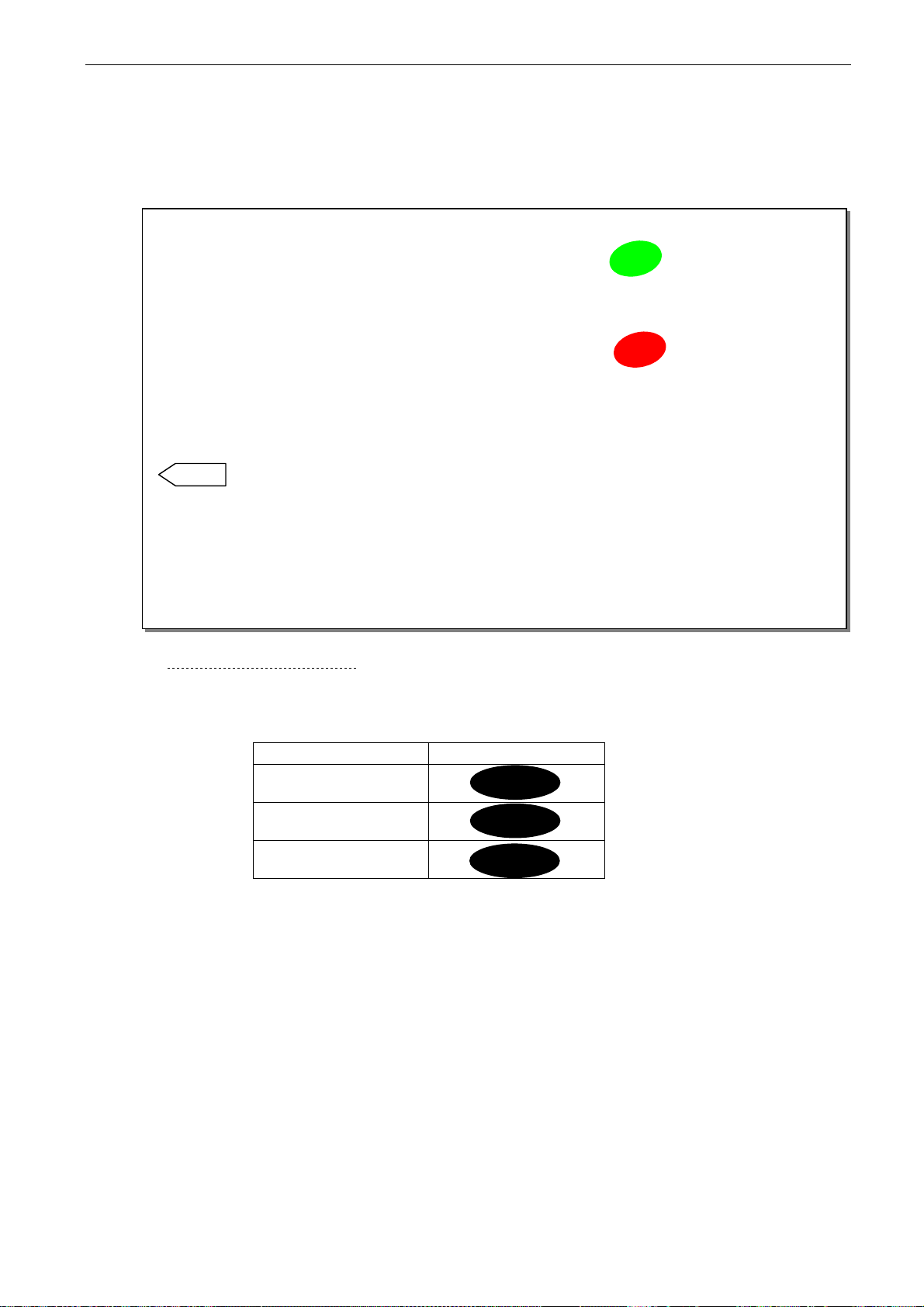
control keypad vacon • 53
Clearwater Tech - Phone: 800.894.0412 - Fax: 208.368.0415 - Web: www.clrwtr.com - Email: [email protected]
7.3.3 Keypad control menu (M3)
In the
Keypad Control Menu
, you can choose the control place, edit the frequency reference and
change the direction of the motor. You can enter the submenu level by pressing
NOTE!
Select the keypad as the active control place by pressing
There are some special functions that can be performed in menu M3:
start
for 3 seconds when
the motor is running. The keypad will become the active control place and the current
frequency reference and direction will be copied to the keypad.
stop
Select the keypad as the active control place by pressing
for 3 seconds when
the motor is stopped. The keypad will become the active control place and the current
frequency reference and direction will be copied to the keypad.
Copy the frequency reference set elsewhere (I/O, fieldbus) to the panel by pressing
enter
for 3 seconds.
Note that if you are in any other than menu M3 these functions will not work.
M3
If you are in some other than menu
when the keypad is not selected as the active control place, you will get an error message:
Control NOT ACTIVE
.
and try to start the motor by pressing the START button
Menu button right
Keypad
.
7.3.3.1 Selection of control place
There are three different places (sources) where the inverter can be controlled from. For each
control place, a different symbol will appear on the alphanumeric display:
Control place Symbol
I/O terminals
Keypad (panel)
Fieldbus
I/O term
Keypad
Bus/Comm
You can change the control place by entering the edit mode with
then be browsed with the
Browser buttons
. Select the desired control place with the
Menu button right
. The options can
enter
button.
See the diagram on the next page.
See also Chapter 7.3.3. above.
7
Page 55
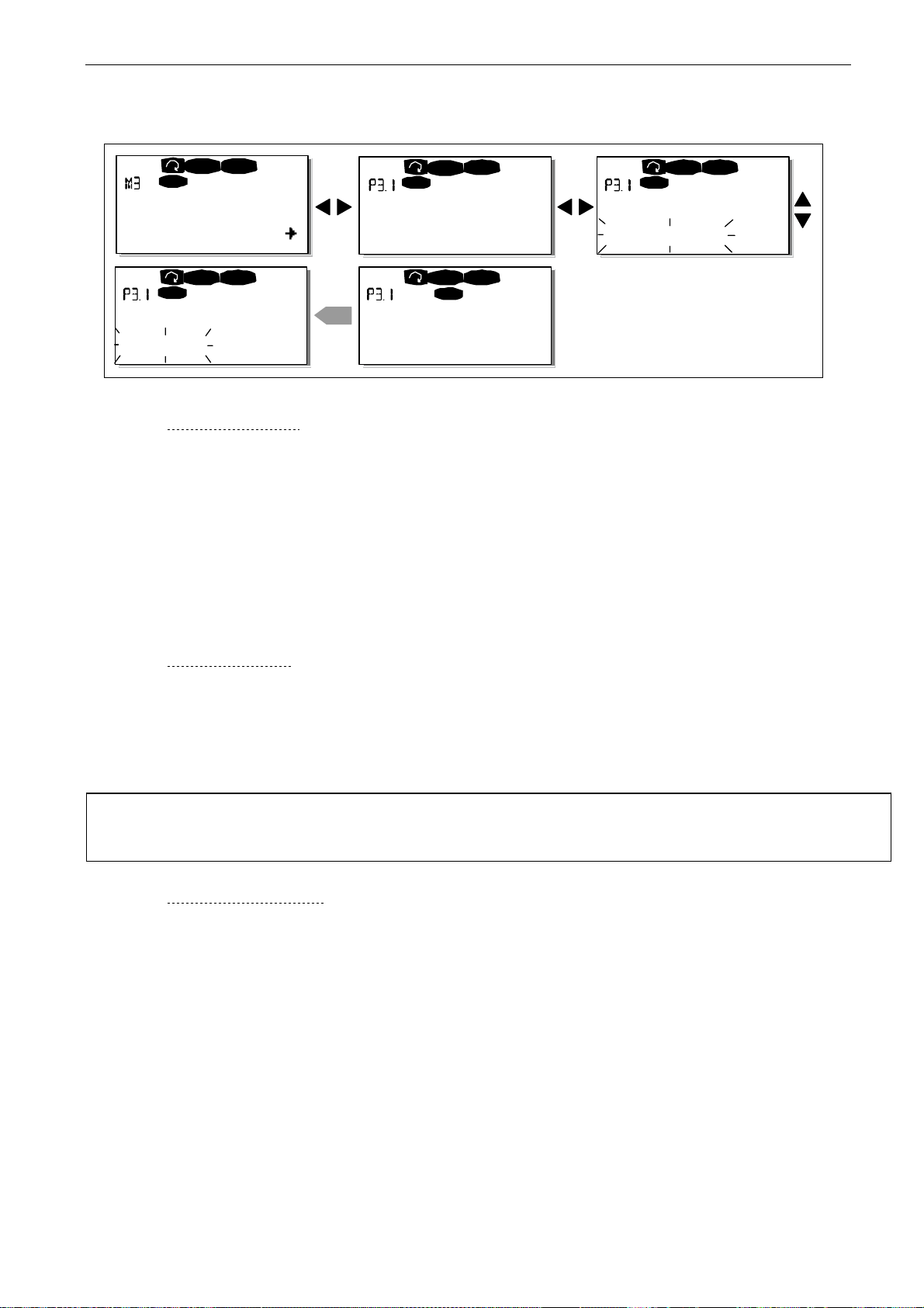
54 • vacon control keypad
Clearwater Tech - Phone: 800.894.0412 - Fax: 208.368.0415 - Web: www.clrwtr.com - Email: [email protected]
READY
I/Oterm
STOP
I/Ote rm
STOP
READY
I/Ote rm
STOP
READY
Keypad control
P1P4
READY
I/Oterm
Control Place
Keypad
Control Place
I/O Remote
enter
Control Place
Keypad
STOPSTOP
Keypad
Control Place
I/O Remote
READY
Figure 7-2. Selection of control place
7.3.3.2 Keypad reference
The keypad reference submenu (P3.2) displays and allows the operator to edit the frequency
reference. The changes will take place immediately. This reference value will not, however,
influence the rotation speed of the motor unless the keypad has been selected as the active
control place.
NOTE: The maximum difference in RUN mode between the output frequency and the keypad
reference is 6 Hz. The program automatically monitors the keypad reference value.
See also Chapter 7.3.3.
Figure 7-1 shows how to edit the reference value (pressing the
enter
button is not necessary).
7.3.3.3 Keypad direction
The keypad direction submenu (P3.3) displays and allows the operator to change the rotating
direction of the motor. This setting will not, however, influence the rotation direction of the
motor unless the keypad has been selected as the active control place.
See also Chapter 7.3.3.
Note: For additional information on controlling the motor with the keypad, see Chapters 7.2.1, 7.3.3
and 8.2.
7.3.3.4 Stop button activated
By default, pushing the STOP button will always stop the motor regardless of the selected control
place. You can disable this function by giving parameter 3.4 the value 0. If the value of this parameter
is 0, the STOP button will stop the motor only when the keypad has been selected as the active
control place.
Tel: +358-201-2121 • Fax: +358-201-212 205
7
Page 56
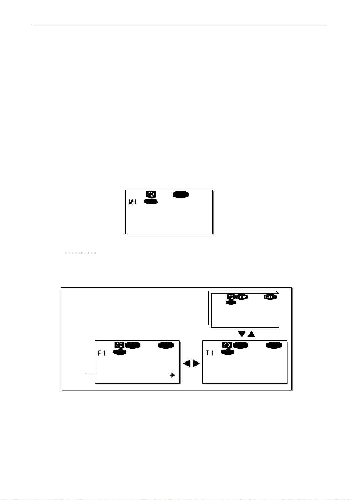
control keypad vacon • 55
Clearwater Tech - Phone: 800.894.0412 - Fax: 208.368.0415 - Web: www.clrwtr.com - Email: [email protected]
7.3.4 Active faults menu (M4)
You can enter the Active faults menu from the Main menu by pressing
location indication M4 is visible on the first line of the keypad display.
When a fault brings the inverter to a stop, the location indication F1, the fault code, a short
description of the fault, and the fault type symbol (see Chapter 7.3.4.1) will appear on the display. In
addition, the indication FAULT or ALARM (see Figure 7-1 or Chapter 7.1.1) is displayed and, in case
of a FAULT, the red LED on the keypad starts to blink. If several faults occur simultaneously, the list
of active faults can be browsed with the
The memory of active faults can store a maximum of 10 faults in the order of appearance. The
display can be cleared with the
before the fault trip. The fault remains active until it is cleared with the
signal from the I/O terminal.
Note! Remove external Start signal before resetting the fault to prevent unintentional restart of the
drive.
Normal state,
no faults
reset
Active faults
Browser buttons
button and the read-out will return to the same state it was in
READY
I/Oterm
.
F0
Menu button right
reset button
or with a reset
when the
7.3.4.1 Fault types
The NX inverter has four types of faults. These types differ from each other on the basis of the
subsequent behaviour of the drive. See Table 7-1.
I/Oterm
Operati on hour s
34:21:05
I/Oterm
Fault type
symbol
Figure 7-3. Fault display
11 Output phase Operations days
F T1
STOP FAULT
T13
I/Oterm
STOP
17
FAULT
7
Page 57
56 • vacon control keypad
Clearwater Tech - Phone: 800.894.0412 - Fax: 208.368.0415 - Web: www.clrwtr.com - Email: [email protected]
Fault type symbol Meaning
A
(Alarm)
F
(Fault)
AR
(Fault Autoreset)
FT
(Fault Trip)
Table 7-1. Fault types
This type of fault is a sign of an unusual operating
condition. It does not cause the drive to stop, nor does it
require any special actions. The 'A fault' remains in the
display for about 30 seconds.
An 'F fault' makes the drive stop. Actions need to be
taken to restart the drive.
If an 'AR fault' occurs the drive will stop immediately.
The fault is reset automatically and the drive tries to
restart the motor. Finally, if the restart is not successful,
a fault trip (FT, see below) occurs.
If the drive is unable to restart the motor after an AR
fault an FT fault occurs. The 'FT fault' has basically the
same effect as the F fault: the drive is stopped.
Tel: +358-201-2121 • Fax: +358-201-212 205
7
Page 58
control keypad vacon • 57
Clearwater Tech - Phone: 800.894.0412 - Fax: 208.368.0415 - Web: www.clrwtr.com - Email: [email protected]
7.3.4.2 Fault codes
The fault codes, their causes and correcting actions are presented in the table below. The shadowed
faults are A faults only. The items in white on black background are faults for which you can
program different responses in the application. See parameter group Protections.
Note! When contacting the distributor or factory because of a fault condition, always write down all
texts and codes visible on the keypad display.
Fault
code
1 Overcurrent Inverter has detected too high a current
2 Overvoltage The DC-link voltage has exceeded the
3 Earth fault Current measurement has detected that
5 Charging switch The charging switch is open, when the
6 Emergency stop Stop signal has been given from the
7 Saturation trip Various causes:
8 System fault component failure
9 Undervoltage DC-link voltage is under the voltage limits
11 Output phase
Fault Possible cause Correcting measures
) in the motor cable:
(>4*I
n
sudden heavy load increase
short circuit in motor cables
unsuitable motor
limits defined in Table 4-3
too short a deceleration time
high overvoltage spikes in supply
the sum of motor phase current is not
zero.
insulation failure in cables or motor
START command has been given.
faulty operation
component failure
option board.
component failure
brake resistor short-circuit or overload
faulty operation
Note the exceptional Fault data record.
See 7.3.4.3.
defined in Table 4-3.
most probable cause: too low a supply
voltage
inverter internal fault
Current measurement has detected that
supervision
there is no current in one motor phase.
Check loading.
Check motor.
Check cables.
Set the deceleration time longer.
Add a brake chopper or a brake resistor.
Check motor cable and motor.
Reset the fault and restart.
Should the fault re-occur, contact the
distributor near to you.
Please visit:
http://www.vacon.com/wwcontacts.html
Cannot be reset from the keypad.
Switch off power.
DO NOT RE-CONNECT POWER!
Contact factory.
If this fault appears simultaneously with
Fault 1, check motor cables and motor
Reset the fault and restart.
Should the fault re-occur, contact the
distributor near to you.
Please visit:
http://www.vacon.com/wwcontacts.html
In case of temporary supply voltage
break, reset the fault and restart the
inverter. Check the supply voltage. If it is
adequate, an internal failure has
occurred.
Contact the nearest Vacon distributor.
Please visit:
http://www.vacon.com/wwcontacts.html
Check motor cable and motor.
7
Page 59
58 • vacon control keypad
Clearwater Tech - Phone: 800.894.0412 - Fax: 208.368.0415 - Web: www.clrwtr.com - Email: [email protected]
12 Brake chopper
supervision
13 Inverter
undertemperatu
re
14 Inverter
overtemperatur
e
15 Motor stalled Motor stall protection has tripped. Check motor. 16 Motor over-
temperature
17 Motor underload Motor underload protection has tripped.
22 EEPROM
checksum fault
24 Counter fault Values displayed on counters are
25 Microprocessor
watchdog fault
26 Start-up
prevented
29 Thermistor fault The thermistor input of option board has
31 IG BT temperature
(hardware)
32 Fan cooling Cooling fan of the inverter does not start,
34 CAN bus
communication
36 Control unit NXS Control Unit can not control NXP
37 Device changed
(same type)
38 Device added
(same type)
39 Device removed Option board removed.
No brake resistor installed
brake resistor is broken
brake chopper failure
Heatsink temperature is under –10°C
Heatsink temperature is over 90°C or
77ºC (NX_6, FR6).
Overtemperature warning is issued when
the heatsink temperature exceeds 85°C
(72ºC).
Motor overheating has been detected by
inverter motor temperature model. Motor
is overloaded.
Parameter save fault
faulty operation
component failure
incorrect
faulty operation
component failure
Start-up of the drive has been prevented. Cancel prevention of start-up.
detected increase of the motor
temperature
IGBT Inverter Bridge overtemperature
protection has detected too high a short
term overload current
when ON command is given.
Sent message not acknowledged. Ensure that there is another device on
Power Unit and vice versa
Option board or control unit changed.
Same type of board or same power rating
of drive.
Option board or drive added.
Drive of same power rating or same type
of board added.
Drive removed.
Check brake resistor.
If the resistor is ok, the chopper is
faulty. Contact the distributor near to
you.
Please visit:
http://www.vacon.com/wwcontacts.html
Check the correct amount and flow of
cooling air.
Check the heatsink for dust.
Check the ambient temperature.
Make sure that the switching frequency
is not too high in relation to ambient
temperature and motor load.
Decrease the motor load.
If no motor overload exists, check the
temperature model parameters.
Reset the fault and restart.
Should the fault re-occur, contact the
distributor near to you.
Please visit:
http://www.vacon.com/wwcontacts.html
Check motor cooling and loading
Check thermistor connection
(If thermistor input of the option board is
not in use it has to be short circuited)
Check loading.
Check motor size.
Contact the nearest Vacon distributor.
Please visit:
http://www.vacon.com/wwcontacts.html
the bus with the same configuration.
Change control unit
Reset
Note: No fault time data record!
Reset
Note: No fault time data record!
Reset
Note: No fault time data record!
Tel: +358-201-2121 • Fax: +358-201-212 205
7
Page 60
control keypad vacon • 59
Clearwater Tech - Phone: 800.894.0412 - Fax: 208.368.0415 - Web: www.clrwtr.com - Email: [email protected]
40 Device unknown Unknown option board or drive. Contact the nearest Vacon distributor.
Please visit:
http://www.vacon.com/wwcontacts.html
41 IG BT temperature IGBT Inverter Bridge overtemperature
protection has detected too high a short
term overload current
42 Brake resistor
overtemperature
43 Encoder fault Note the exceptional Fault data record.
44 Device changed
(different type)
45 Device added
(different type)
50 Analogue input
(sel. signal
range 4 to 20
mA)
51 External fault Digital input fault. 52 Keypad
communication
fault 53 Fieldbus fault The data connection between the fieldbus
54 Slot fault Defective option board or slot Check board and slot.
56 PT100 board
temp. fault
<0}
Brake resistor overtemperature
protection has detected too heavy braking
See 7.3.4.3. Additional codes:
1 = Encoder 1 channel A is missing
2 = Encoder 1 channel B is missing
3 = Both encoder 1 channels are missing
4 = Encoder reversed
Option board or control unit changed.
Option board of different type or different
power rating of drive.
Option board or drive added.
Option board of different type or drive of
different power rating added.
Current at the analogue input is < 4mA.
control cable is broken or loose
signal source has failed
There is no connection between the
control keypad and the inverter.
Master and the fieldbus board is broken
Temperature limit values set for the
PT100 board parameters have been
exceeded
Check loading.
Check motor size.
Set the deceleration time longer.
Use external brake resistor.
Check encoder channel connections.
Check the encoder board.
Reset
Note: No fault time data record!
Note: Application parameter values
restored to default.
Reset
Note: No fault time data record!
Note: Application parameter values
restored to default.
Check the current loop circuitry.
Check keypad connection and possible keypad cable.
Check installation.
If installation is correct contact the
nearest Vacon distributor.
Please visit:
http://www.vacon.com/wwcontacts.html
Contact the nearest Vacon distributor.
Please visit:
http://www.vacon.com/wwcontacts.html
Find the cause of temperature rise
Table 7-2. Fault codes
7
Page 61
60 • vacon control keypad
Clearwater Tech - Phone: 800.894.0412 - Fax: 208.368.0415 - Web: www.clrwtr.com - Email: [email protected]
7.3.4.3 Fault time data record
When a fault occurs, the information described in Chapter 7.3.3.4 is displayed. By pressing
button right,
some selected important data valid at the time of the fault are recorded. This feature will help the
user or the service person in determining the cause of the fault.
The data available are:
T.1 Counted operation days
you will enter the
Fault time data record menu
(d)
indicated by T.1T.#. In this menu,
Menu
(Fault 43: Additional code)
T.2 Counted operation hours
(Fault 43: Counted operation days)
T.3 Output frequency
(Fault 43: Counted operation hours)
T.4 Motor current A T.5 Motor voltage V T.6 Motor power % T.7 Motor torque % T.8 DC voltage V
T.9 Unit temperature °C T.10 Run status T.11 Direction T.12 Warnings T.13 0-speed*
Table 7-3. Fault time recorded data
(hh:mm:
ss)
(d)
Hz
(hh:mm:
ss)
* Tells the user if the drive was at zero speed (< 0.01 Hz) when the fault occurred
Real time record
If real time is set to run on the inverter, the data items T1 and T2 will appear as follows:
T.1 Counted operation days
T.2 Counted operation hours
yyyy-mm-dd
hh:mm:ss,sss
Tel: +358-201-2121 • Fax: +358-201-212 205
7
Page 62
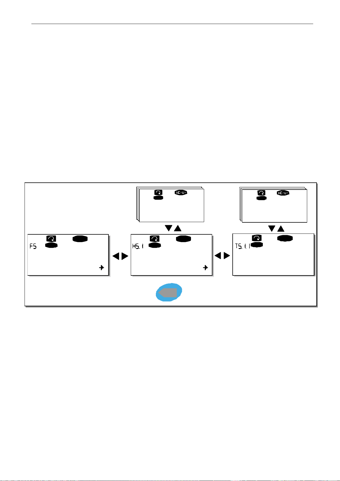
control keypad vacon • 61
Clearwater Tech - Phone: 800.894.0412 - Fax: 208.368.0415 - Web: www.clrwtr.com - Email: [email protected]
7.3.5 Fault history menu (M5)
You can enter the
location indication M5 is visible on the first line of the keypad display.
All faults are stored in the
Additionally, the
can return to the previous menu any time by pressing
The memory of the inverter can store a maximum of 30 faults in order of appearance. The number of
faults currently in the fault history is shown on the value line of the main page (H1H#). The order
of the faults is indicated by the location indication in the upper left corner of the display. The latest
fault is indicated by F5.1, the one before that by F5.2 and so on. If there are 30 uncleared faults in the
memory, the next fault will erase the oldest fault from the memory.
Pressing the
change to 0.
Fault history menu
Fault history menu
Fault time data record
enter
button for about 2 to 3 seconds resets the whole fault history. The symbol H# will
from the
pages (see Chapter 7.3.4.3) are accessible for each fault. You
Main menu
where you can browse them with the
I/Oterm
by pressing
Menu button left
Menu button right
.
5 ChargeSwitch
Browser buttons
I/Oter m
Operation hours
when the
13:25:43
.
I/Oterm
READY
I/Oterm
READY
Fault history 11 Output ph ase
H1
Figure 7-4. Fault history menu
H3
T1T7
PUSH to reset
enter
READY
I/Oterm
Operation days
17
7
Page 63

62 • vacon control keypad
Clearwater Tech - Phone: 800.894.0412 - Fax: 208.368.0415 - Web: www.clrwtr.com - Email: [email protected]
7.3.6 System menu (M6)
You can enter the
location indication M6 is visible on the first line of the keypad display
The controls associated with the general use of the inverter, such as application selection,
customised parameter sets or information about the hardware and software are located under the
System menu.
value line.
Page 63 has a table of the functions available in the System menu.
System menu
The number of submenus and subpages is shown with the symbol S (or P) on the
from the
Main menu
by pressing
Menu button right
.
when the
Tel: +358-201-2121 • Fax: +358-201-212 205
7
Page 64
control keypad vacon • 63
Clearwater Tech - Phone: 800.894.0412 - Fax: 208.368.0415 - Web: www.clrwtr.com - Email: [email protected]
System menu functions
Code Function Min Max Unit Default Cust Selections
S6.1
S6.2 Application selection
S6.3 Copy parameters
S6.3.1 Parameter sets
S6.3.2 Load to keypad
S6.3.3 Load from keypad
P6.3.4 Parameter backup
S6.4
S6.5 Safety
S6.5.1 Password
P6.5.2 Parameter locking
S6.5.3 Start-up wizard
S6.5.4
S6.6 Keypad settings P6.6.1 Default page P6.6.2 Default page/OM P6.6.3 Timeout time 0 65535 s 30 P6.6.4 Contrast 0 31 P6.6.5 Backlight time Always 65535 min 10
S6.7 Hardware settings
P6.7.1
P6.7.2 Fan control function
P6.7.3 HMI acknowledg. 200 5000 ms 200 P6.7.4 HMI: no. of retries 1 10
S6.8 System information S6.8.1 Total counters
C6.8.10.1. MWh counter
C6.8.10.2.
C6.8.1.3.
S6.8.2 Trip counters
T6.8.2.1 MWh counter T6.8.2.2 Clear MWh counter
Selection of
language
Parameter
comparison
Multimonitoring
items
Internal brake
resistor
Operation day
counter
Operation hour
counter
English
Application
kWh
kWh
Not used
Change
Enabled
Change
Enabled
Connected
Continuous
Basic
Yes
18
5
English
Deutsch
Suomi
Svenska
Italiano
Basic Application
Standard Application
Local/Remote control Appl.
Multi-Step Application
PID Control Application
Multi-Purpose Control Appl.
Pump and Fan Control Appl.
Load factory defaults
Store set 1
Load set 1
Store set 2
Load set 2
All parameters
All parameters
All but motor parameters
Application parameters
No
Yes
0=Not used Change Enabled
Change Disabled
No
Yes
Change Enabled
Change Disabled
Not connected
Connected
Continuous
Temperature
7
Page 65
64 • vacon control keypad
Clearwater Tech - Phone: 800.894.0412 - Fax: 208.368.0415 - Web: www.clrwtr.com - Email: [email protected]
T6.8.2.3
T6.8.2.4
T6.8.2.5
S6.8.3 Software information
S6.8.3.1 Software package
S6.8.3.2
S6.8.3.3 Firmware interface S6.8.3.4 System load
S6.8.4 Applications
S6.8.4.#
D6.8.4.#.1 Application ID
D6.8.4.#.2 Applications: version
D6.8.4.#.3
S6.8.5 Hardware I6.8.5.1 Unit power I6.8.5.2 Unit voltage I6.8.5.3 Info: Brake chopper I6.8.5.4 Info: Brake resistor
S6.8.6 Expander boards
Operation day
counter
Operation hour
counter
Clear operation hour
counter
System software
version
Name of application
Applications:
firmware interface
Table 7-4. System menu functions
Tel: +358-201-2121 • Fax: +358-201-212 205
7
Page 66
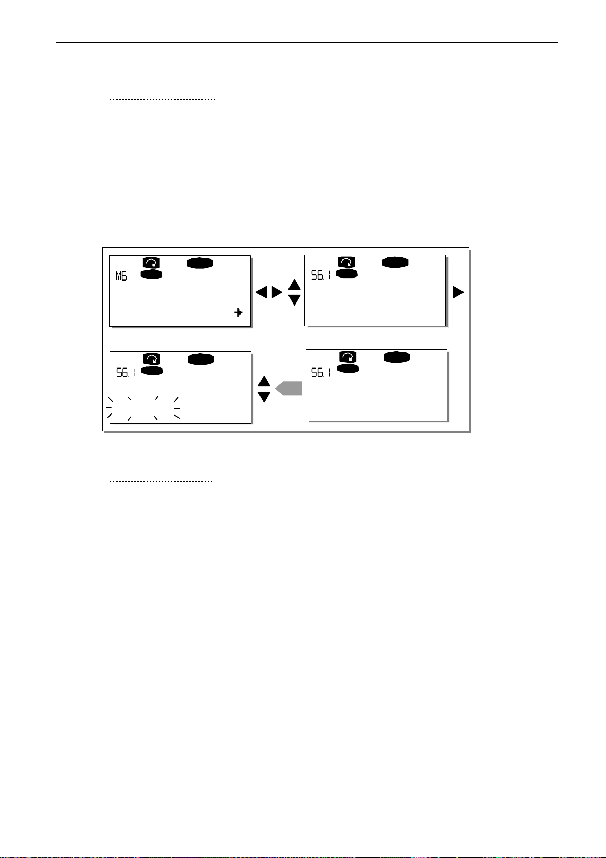
control keypad vacon • 65
Clearwater Tech - Phone: 800.894.0412 - Fax: 208.368.0415 - Web: www.clrwtr.com - Email: [email protected]
7.3.6.1 Selection of language
The Vacon control keypad offers you the possibility to control the inverter through the keypad in the
language of your choice.
Locate the language selection page under the
Menu button right
select another language for the keypad texts. Confirm with the
all text information on the keypad is presented in the selected language.
You can return to the previous menu any time by pressing
once to enter the edit mode. As the name of the language starts to blink you can
System menu
Menu button left
. Its location indication is S6.1. Press
enter
button. The blinking stops and
.
READY
I/Oterm
System Menu
S1S11
READY
I/Oterm
Language
enter
English
Figure 7-5. Selection of language
I/Oterm
Language
English
I/Oterm
Langue
Francais
READY
READY
7.3.6.2 Application selection
The user can select the desired application on the
page, press
press
the applications with the
After application change, you will be asked if you want the parameters of the new application to be
uploaded to the keypad. If you want to do this, press the
leaves the parameters of the previously used application saved in the keypad. For more information,
see Chapter 7.3.6.3.
For more information about the Application Package, see Vacon NX Application Manual.
Menu button right
Menu button right
on the first page of the
once more. The name of the application starts to blink. Now you can browse
Browser buttons
and select the desired application with the
Application selection page (S6.2)
System menu
enter
. To change the application,
button. Pressing any other button
. To enter the
enter
button.
7
Page 67
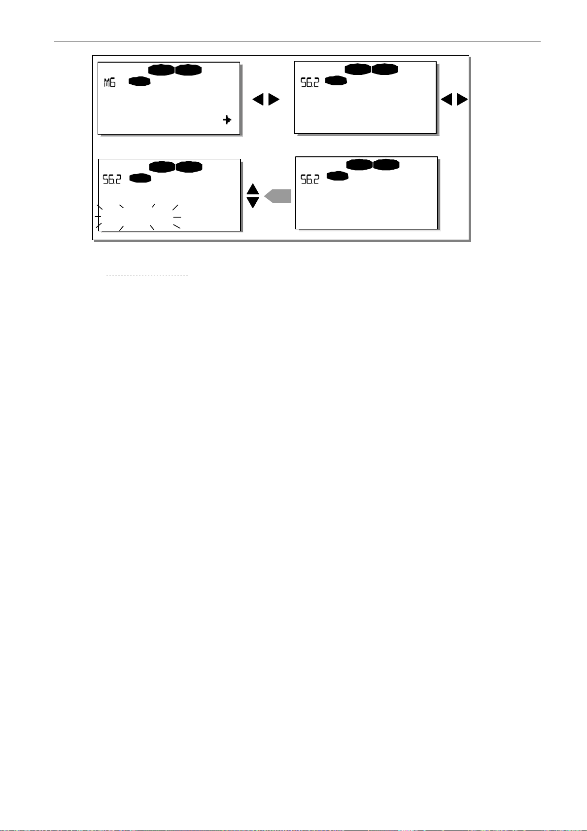
66 • vacon control keypad
Clearwater Tech - Phone: 800.894.0412 - Fax: 208.368.0415 - Web: www.clrwtr.com - Email: [email protected]
STOP READY
I/Oterm
System Menu
S1S11
STOP READY
I/Oterm
Application
St andard
Figure 7-6. Change of application
Application
St andard
enter
Application
Multi-step
STOP READY
I/Oterm
STOP READY
I/Oterm
7.3.6.3 Copy parameters
The parameter copy function is used when the operator wants to copy one or all parameter groups
from one drive to another. All the parameter groups are first
keypad is connected to another drive and then the parameter groups are
possibly back to the same drive). For more information, see page 67.
Before any parameters can be successfully copied from one drive to another, the drive has to be
stopped when the parameters are downloaded to it:
The parameter copy menu (S6.3) contains four functions:
Parameter sets (S6.3.1)
The user can reload the factory default parameter values and store and load two customised
parameter sets (all parameters included in the application).
On the
LoadFactDef
enter
Alternatively, you can choose any other storing or loading functions with the
Confirm with the
Parameter sets
begins to blink and you can confirm the loading of factory defaults by pressing the
button. The drive resets automatically.
page (S6.3.1), press
enter
button. Wait until 'OK' appears on the display.
Menu button right
uploaded
to enter the
to the keypad, then the
downloaded
edit mode
to it (or
. The text
Browser buttons
.
Tel: +358-201-2121 • Fax: +358-201-212 205
7
Page 68
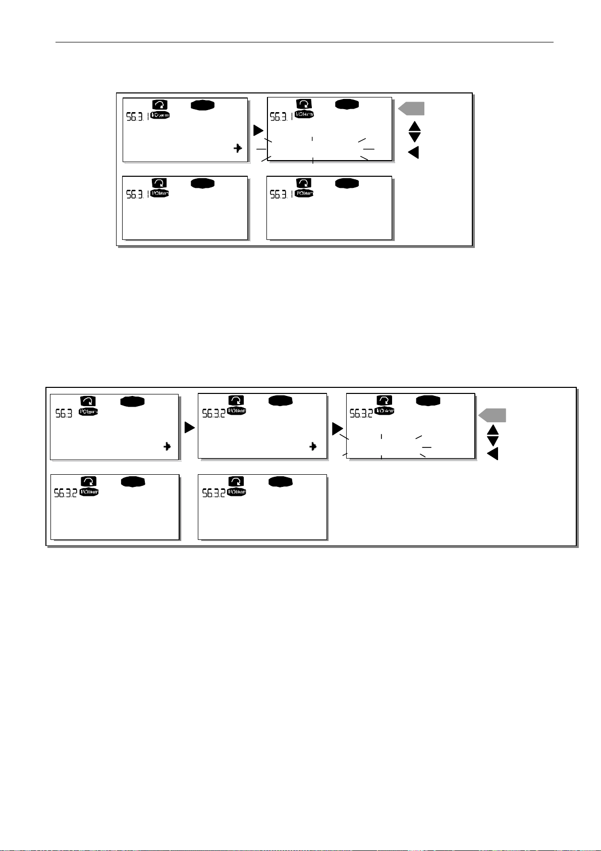
control keypad vacon • 67
E
Clearwater Tech - Phone: 800.894.0412 - Fax: 208.368.0415 - Web: www.clrwtr.com - Email: [email protected]
READY
Parameter sets
Select
READY READY
P a rameter set s
Wait...
Figure 7-7. Storing and loading of parameter sets
Upload parameters to keypad (To keypad, S6.3.2)
This function uploads all existing parameter groups to the keypad provided that the drive is stopped.
Enter the
you to the edit mode. Use the
enter
To keypad
page (S6.3.2) from the
Browser buttons
button. Wait until 'OK' appears on the display.
Parameter sets
LoadFactDef
P aramete r sets
OK
Parameter copy menu
to select the option
READY
enter
CONFIRM
CANCEL
. Pressing
Menu button right
All parameters
takes
and press the
READY
Copy Parameters
P1
P4
READY READY
Up to keypad
Wait...
Figure 7-8. Parameter copy to keypad
Download parameters to drive (From keypad, S6.3.3)
This function downloads one or all parameter groups uploaded to the keypad to a drive provided
that the drive is in STOP status.
Enter the
takes you to the edit mode. Use the
parameters
display.
The procedure to download the parameters from keypad to drive is similar to that of from drive to
keypad. See Figure 7-8.
To keypad
or
page (S6.3.2) from the
Application parameters
Up to keypad
Select
Up to keypad
OK
Browser buttons
READY READY
Up to ke ypad
All param.
Parameter copy menu
to select either
and press the
Enter button
. Pressing the
. Wait until 'OK' appears on the
CONFIRM
enter
CHANGE VA LU
CANCEL
Menu button right
All parameters, All but motor
7
Page 69

68 • vacon control keypad
Clearwater Tech - Phone: 800.894.0412 - Fax: 208.368.0415 - Web: www.clrwtr.com - Email: [email protected]
Automatic parameter backup (P6.3.4)
On this page you can activate or inactivate the parameter backup function. Enter the edit mode by
pressing
When the Parameter backup function is activated Vacon NX control keypad makes a copy of the
parameters of the presently used application. When applications are changed, you will be asked if
you wish the parameters of the new application to be uploaded to the keypad. If you want to do this,
press the
application saved in the keypad, press any other button. Now you will be able to download these
parameters to the drive following the instructions given in Chapter 7.3.6.3.
If you want the parameters of the new application to be automatically uploaded to the keypad you
have to do this for the parameters of the new application once on page 6.3.2 as instructed.
Otherwise the panel will always ask for the permission to upload the parameters.
Note: Parameters saved in the parameter settings on page S6.3.1 will be deleted when applications
are changed. If you want to transfer the parameters from one application to another, you have to
upload them first to the keypad.
Menu button right.
enter
button. If you wish to keep the copy of the parameters of the previously used
Select
Yes
or
No
with the
Browser buttons.
7.3.6.4 Parameter comparison
In the
values of your customised parameter sets and those loaded to the control keypad.
You can compare the parameter by pressing
submenu
Set1. If no differences are detected, '0' is displayed on the lowermost line. If any of the parameter
values differ from those of Set1, the number of the deviations is displayed together with symbol P
(for example, P1P5 = five deviating values). By pressing
enter pages where you can see both the actual value and the value it was compared to. In this
display, the value on the description line (in the middle) is the default value and the one on the value
line (lowermost) is the edited value. Furthermore, you can also edit the actual value with the
Browser buttons
Parameter comparison
. The actual parameter values are first compared to those of the customised parameter
in the
edit mode
submenu (S6.4), you can compare the actual parameter values to the
Menu button right
which you can enter by pressing
in the
Compare parameters
Menu button right
Menu button right
once more, you can
once.
Tel: +358-201-2121 • Fax: +358-201-212 205
7
Page 70
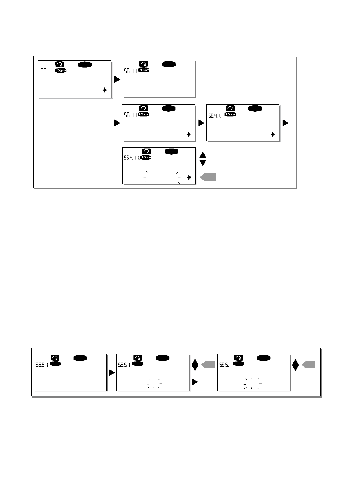
control keypad vacon • 69
Clearwater Tech - Phone: 800.894.0412 - Fax: 208.368.0415 - Web: www.clrwtr.com - Email: [email protected]
READY
ParamComparison
C1C3
Set1
OR
Set1
READY
0
READY
P1P6
READY
READY
P2.1 .2= 50.0
20.0 Hz
EDIT VALUE
P2.1 .2= 50.0
CONFIRM CHA NGE
.
enter
Menu button right
Menu button right
Timeout time
again
, and
20.0 Hz
Figure 7-9. Parameter comparison
7.3.6.5 Safety
NOTE: The
Password (S6.5.1)
The application selection can be protected against unauthorised changes with the Password function
(S6.5.1).
By default, the password function is not in use. If you want to activate the function, enter the edit
mode by pressing
password with the
Note that you can also set the password by digits. In the edit mode, push
and another zero appears on the display. Set ones first. To set the tens, press
so on. Confirm the password with the
(P6.6.3) (see page 72) has expired before the password function is activated.
If you try to change applications or the password itself, you will be prompted for the current
password. Enter the password with the
You can deactivate the password function by entering the value 0.
Security submenu
Menu button right
Browser buttons
is protected with a password. Store the password in a safe place!
. A blinking zero appears in the display and you can set a
. The password can be any number between 1 and 65535.
enter
button. After this, you have to wait until the
Browser buttons
I/Oterm
READY
Password
Not in use
Figure 7-10. Password setting
I/Oterm
Password Password
0
READY
OR:
enter
I/Oterm
READY
00
Note! Store the password in a safe place! No changes can be made unless a valid password is
entered.
enter
7
Page 71
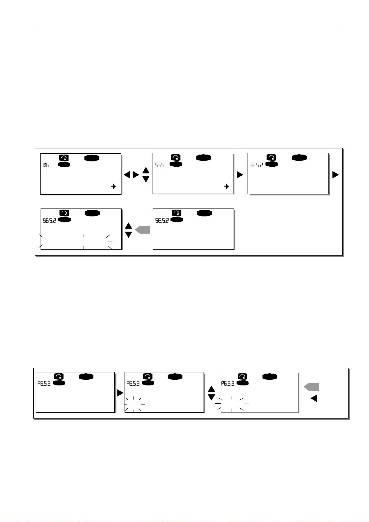
70 • vacon control keypad
Clearwater Tech - Phone: 800.894.0412 - Fax: 208.368.0415 - Web: www.clrwtr.com - Email: [email protected]
Parameter lock (P6.5.2)
This function allows the user to prohibit changes to the parameters.
If the parameter lock is activated, the text
*locked*
will appear on the display if you try to edit a
parameter value.
NOTE: This function does not prevent unauthorised editing of parameter values.
Enter the edit mode by pressing
parameter lock status. Confirm the change with the
pressing
Menu button left.
Menu button right.
Use the
enter
Browser buttons
to change the
button or go back to the previous level by
READY
I/Oterm
System Menu
S1S9
READY
I/Oterm
Parameter Lock
ChangeEnable
I/Oterm
Security
P1P4
I/Oterm
enter
Parameter Lock
ChangeDisabl
READY
I/Oterm
Parameter Lock
ChangeEnable
READY
READY
Figure 7-11. Parameter locking
Start-up wizard (P6.5.3)
The Start-up wizard facilitates the commissioning of the inverter. If active, the Start-up wizard
prompts the operator for the language and application of his/her choice and then displays the first
menu or page.
Activating the Start-up wizard: In the System Menu, find page P6.5.3. Press
to enter the edit mode. Use the
enter
button. If you want to deactivate the function, follow the same procedure and give the
parameter value
No
.
Browser buttons
to select
Yes
and confirm the selection with the
Menu button right
once
I/Oterm
READY
I/Oterm
Startup wizard Startup wizard
No No
READY
I/Oterm
READY
Startup wizard
Yes
enter
CONFIRM
CANCEL
Figure 7-12. Activation of Start-up wizard
Tel: +358-201-2121 • Fax: +358-201-212 205
7
Page 72
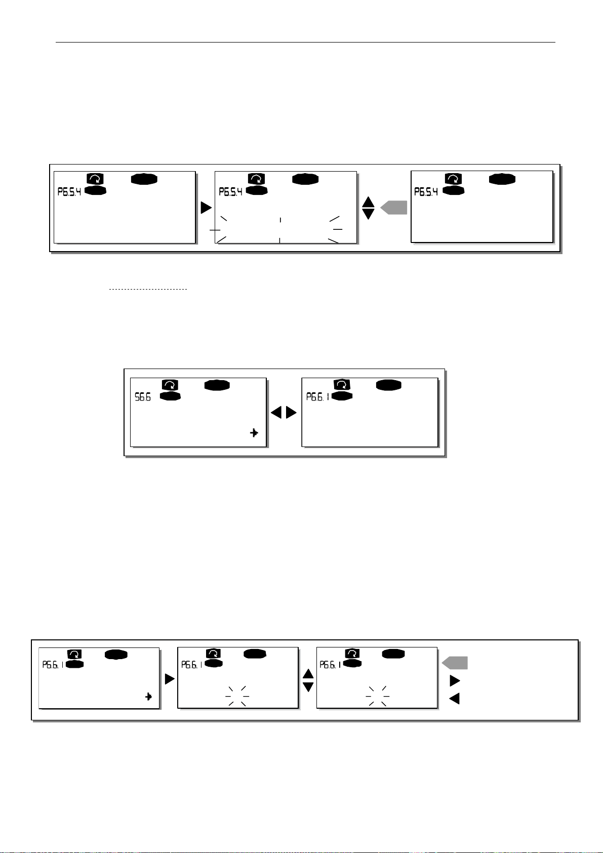
control keypad vacon • 71
E
Clearwater Tech - Phone: 800.894.0412 - Fax: 208.368.0415 - Web: www.clrwtr.com - Email: [email protected]
Multimonitoring items (P6.5.4)
Vacon alphanumeric keypad features a display where you can monitor up to three actual values at
the same time (see Chapter 7.3.1 and Chapter
Monitoring values
in the manual of the application you
are using). On page P6.5.4 of the System Menu, you can define whether the operator can replace the
values monitored with other values. See below.
READY
I/Oterm
Multimon. ite ms
ChangeEnable
I/Oterm
Multimon. items Multimon. items
ChangeEnable ChangeDisable
READY
READY
I/Oterm
enter
Figure 7-13. Disabling the change of multimonitoring items
7.3.6.6 Keypad settings
In the Keypad settings submenu under the System menu, you can further customise your inverter
operator interface
.
Locate the Keypad setting submenu (S6.6). Under the submenu, there are four pages (P#)
associated with the keypad operation:
READ Y
I/Oterm
Keypad setting s
P1P5
I/Oterm
Default page
READY
0.
Figure 7-14. Keypad settings submenu
Default page (P6.6.1)
Here you can set the location (page) to which the display automatically moves when the
time
(see below) has expired or the power is switched on to the keypad.
Default page
If the
keypad display. Pressing
Main menu with the
right
. If the page you want to move to by default is at the third level, repeat the procedure. Confirm
the new default page with the
pressing
Menu button left
is 0, the function is not activated i.e. the latest displayed page remains on the
Menu button right
Browser buttons
enter
button. You can return to the previous menu at any time by
. To edit the number of the submenu/page, press
takes you to the edit mode. Change the number of the
.
I/Oterm
0.
READY
I/Oterm
Default pageDefault page
READY
I/Oterm
Default pag e
0.
READY
enter
1.
Figure 7-15. Default page function
Timeout
Menu button
CONFIRM CHANGE
REPEA T TO SET
DE F AUL T S U B M E N U / PAG
CANCEL
7
Page 73
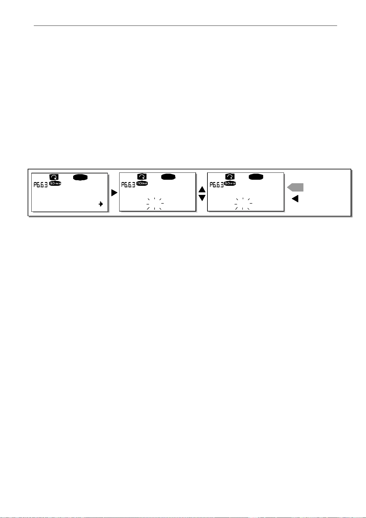
72 • vacon control keypad
E
Clearwater Tech - Phone: 800.894.0412 - Fax: 208.368.0415 - Web: www.clrwtr.com - Email: [email protected]
Default page in the operating menu (P6.6.2)
Here you can set the location (page) in the
the display automatically moves to when the set
is switched on to the keypad.
See how to set the Default page in the above figure.
Timeout time (P6.6.3)
The Timeout time setting defines the time after which the keypad display returns to the Default page
(P6.6.1). (See previous page.)
Enter the edit mode by pressing
the
enter
button. You can return to the previous menu at any time by pressing
Menu button right
Operating menu
Timeout time
. Set the desired timeout time and confirm it with
(in special applications only) to which
(see below) has expired or the power
Menu button left
.
READY
Timeout time
Timeout time Timeout time
90 s
Figure 7-16. Timeout time setting
Note: If the
Contrast adjustment (P6.6.4)
In case the display is unclear, you can adjust its contrast through the same procedure as for the
timeout time setting (see above).
Backlight time (P6.6.5)
By giving a value for the
going out. You can select any time between 1 and 65535 minutes or 'Forever'. For the value setting
procedure, see Timeout time (P6.6.3).
Default page
value is 0 the
Backlight time
READY READY
CONFIRM CH ANG
enter
CANCEL
90 s.
Timeout time
, you can determine how long the backlight stays on before
setting has no effect.
60 s.
Tel: +358-201-2121 • Fax: +358-201-212 205
7
Page 74
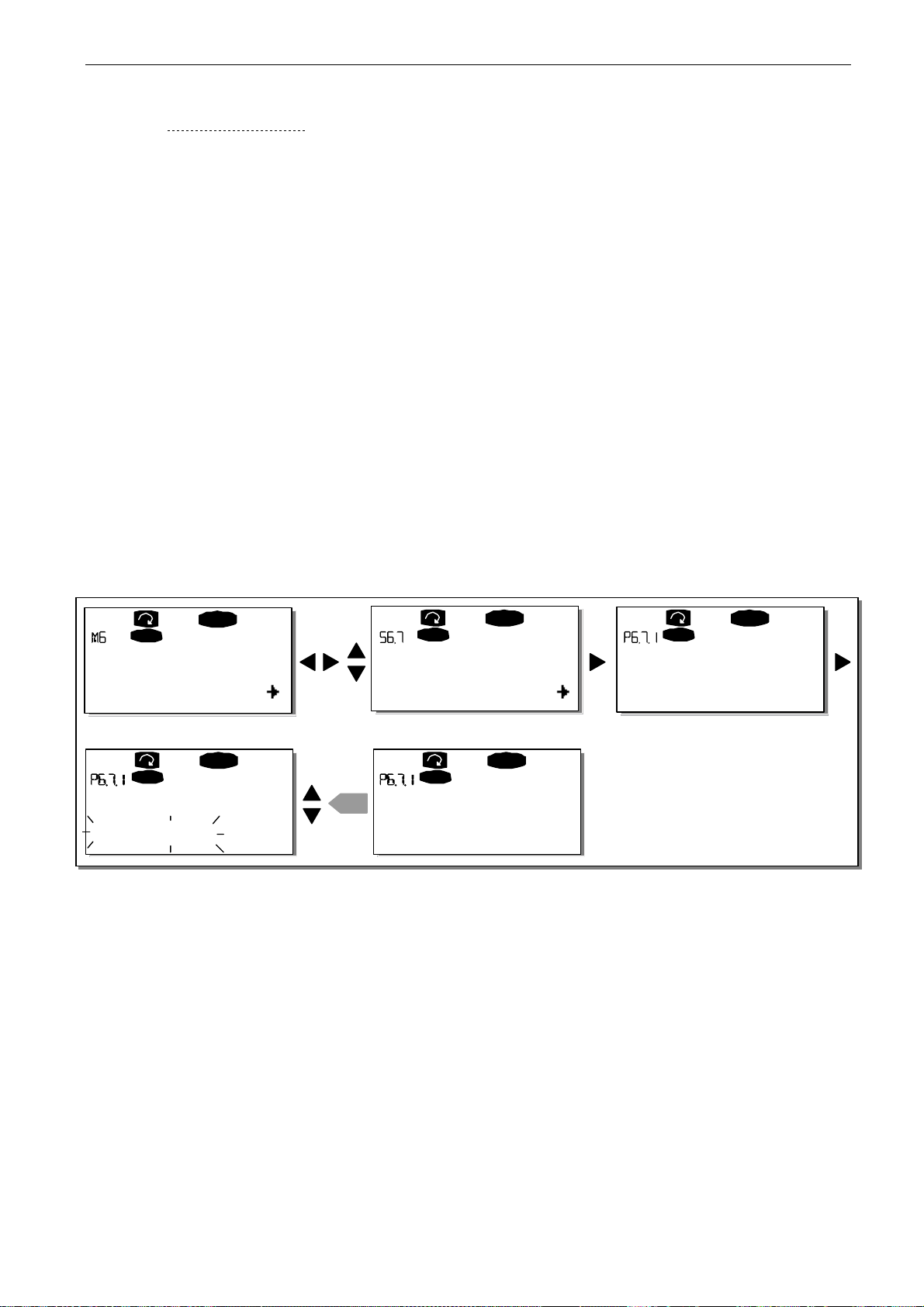
control keypad vacon • 73
Clearwater Tech - Phone: 800.894.0412 - Fax: 208.368.0415 - Web: www.clrwtr.com - Email: [email protected]
7.3.6.7 Hardware settings
NOTE:
place!
In the
functions of the hardware in your inverter. The functions available in this menu are
The Hardware settings submenu
Hardware settings
submenu (S6.7) under the System menu, you can further control some
is protected with a password. Store the password in a safe
Internal brake
resistor connection, Fan control, HMI acknowledge timeout and HMI retry.
Internal brake resistor connection (P6.7.1)
This function tells the inverter, whether the internal brake resistor is connected or not. If you have
ordered the inverter with an internal brake resistor, the default value of this parameter is
Connected
resistor, or if the internal brake resistor is disconnected for another reason, it is advisable to change
the value of this function to
Enter the edit mode by pressing
with the
with
Note! The brake resistor is available as optional equipment for all classes. It can be installed
internally in classes FR4 to FR6.
. However, if it is necessary to increase braking capacity by installing an external brake
Browser buttons
Menu button left
Not conn.
. Confirm the change with the
.
in order to avoid unnecessary fault trips.
Menu button right
. You can change the brake resistor information
enter
button or return to the previous level
READY
I/Oterm
System Menu
S1S8
READY
I/Oterm
InternBrakeRes
enter
Connected
Figure 7-17. Internal brake resistor connection
Fan control (P6.7.2)
This function allows you to control the cooling fan of the inverter. You can set the fan to run continuously when the power is switched on or depending on the temperature of the unit. If the latter
function has been selected, the fan is switched on automatically when the heatsink temperature
reaches 60°C. The fan receives a stop command when the heatsink temperature falls to 55°C. After
the command, the fan runs for approximately 1 minute before stopping. The same happens after
switching on the power and after changing the value from
Note! The fan runs always when the drive is in RUN state.
I/Oterm
HW settings
P1P4
I/Oterm
InternBrakeRes
No t c onn.
READY
READY
Continuous
I/Oterm
InternBrakeRes
Connected
to
Temperature
READY
.
7
Page 75
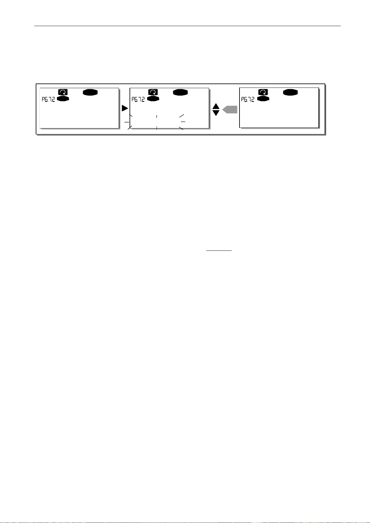
74 • vacon control keypad
Clearwater Tech - Phone: 800.894.0412 - Fax: 208.368.0415 - Web: www.clrwtr.com - Email: [email protected]
To change the value: Enter the edit mode by pressing
Use the
Browser buttons
to change the fan mode and confirm the change with the
you do not want to change the value, return to the previous level with
Menu button right
Menu button left
. The value starts blinking.
enter
button. If
. See Figure
7.21 .
I/Oterm
READY
Fan control
Continuous
Figure 7-18. Fan control function
HMI acknowledge timeout (P6.7.3)
I/Oterm
Fan control Fan control
Continuous
READY
I/Oterm
READY
enter
Temperature
This function allows the user to change the timeout of the HMI acknowledgement time. The inverter
waits for the HMI acknowledgment in accordance with the value of this parameter.
Note! If the inverter has been connected to the PC with a normal cable, the default values of
parameters 6.7.3 and 6.7.4 (200 and 5) must not be changed.
If the inverter has been connected to the PC via a modem and there is a delay in transferring
messages, the value of parameter 6.7.3 must be set according to the delay as follows:
Example:
Transfer delay between the inverter and the PC = 600 ms The value of par. 6.7.3 is set to 1200 ms
(2 x 600, sending delay + receiving
delay)
The corresponding setting shall be entered in the [Misc] part of the file
NCDrive.ini:
Retries = 5
AckTimeOut = 1200
TimeOut = 6000
It must also be considered that intervals shorter than the AckTimeOut time
cannot be used in NC-Drive monitoring.
Enter the edit mode by pressing
Browser buttons
to change the acknowledgement time. Confirm the change with the
Menu button right
. The current value starts to blink. Use the
enter
button or
return to the previous level with Menu button left.
Tel: +358-201-2121 • Fax: +358-201-212 205
7
Page 76
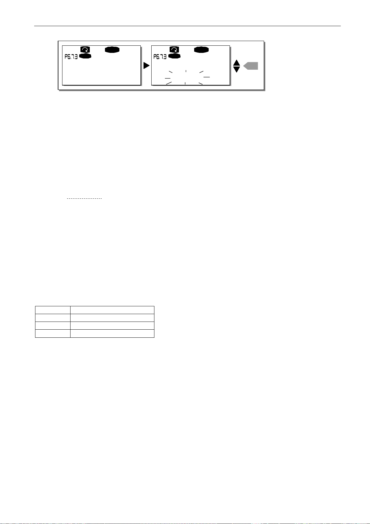
control keypad vacon • 75
Clearwater Tech - Phone: 800.894.0412 - Fax: 208.368.0415 - Web: www.clrwtr.com - Email: [email protected]
I/Oterm
HMI ACK timeout
READY
HMI ACK timeout
200ms
Figure 7-19. HMI acknowledge timeout
I/Oterm
200ms
READ Y
enter
Number of retries to receive HMI acknowledgement (P6.7.4)
With this parameter you can set the number of times the drive will try to receive acknowledgement if
it does not receive acknowledgement within the acknowledgement time (P6.7.3) or if the received
acknowledgement is faulty.
You can change value through the same procedure as for P6.7.3 (see above).
Note! Changes to P6.7.3 and P6.7.4 become effective after the next start-up.
7.3.6.8 System info
In the System info submenu (S6.8) you can find inverter-related hardware and software information.
You can enter the
submenu pages with the
System info submenu
Browser buttons
by pressing
.
Menu button right
. You can now browse the
Total counters
The
Total counters menu
(S6.8.1) contains information on the inverter operation times i.e. the total
number of MWh, operation days and operation hours. Unlike the counters in the Trip counters menu,
these counters cannot be reset.
Note! The Power On time counter (days and hours) runs always when the power is on.
Page Counter C6.8.10.1. MWh counter C6.8.10.2. Operation day counter
C6.8.1.3. Operation hour counter
Table 7-5. Counter pages
7
Page 77
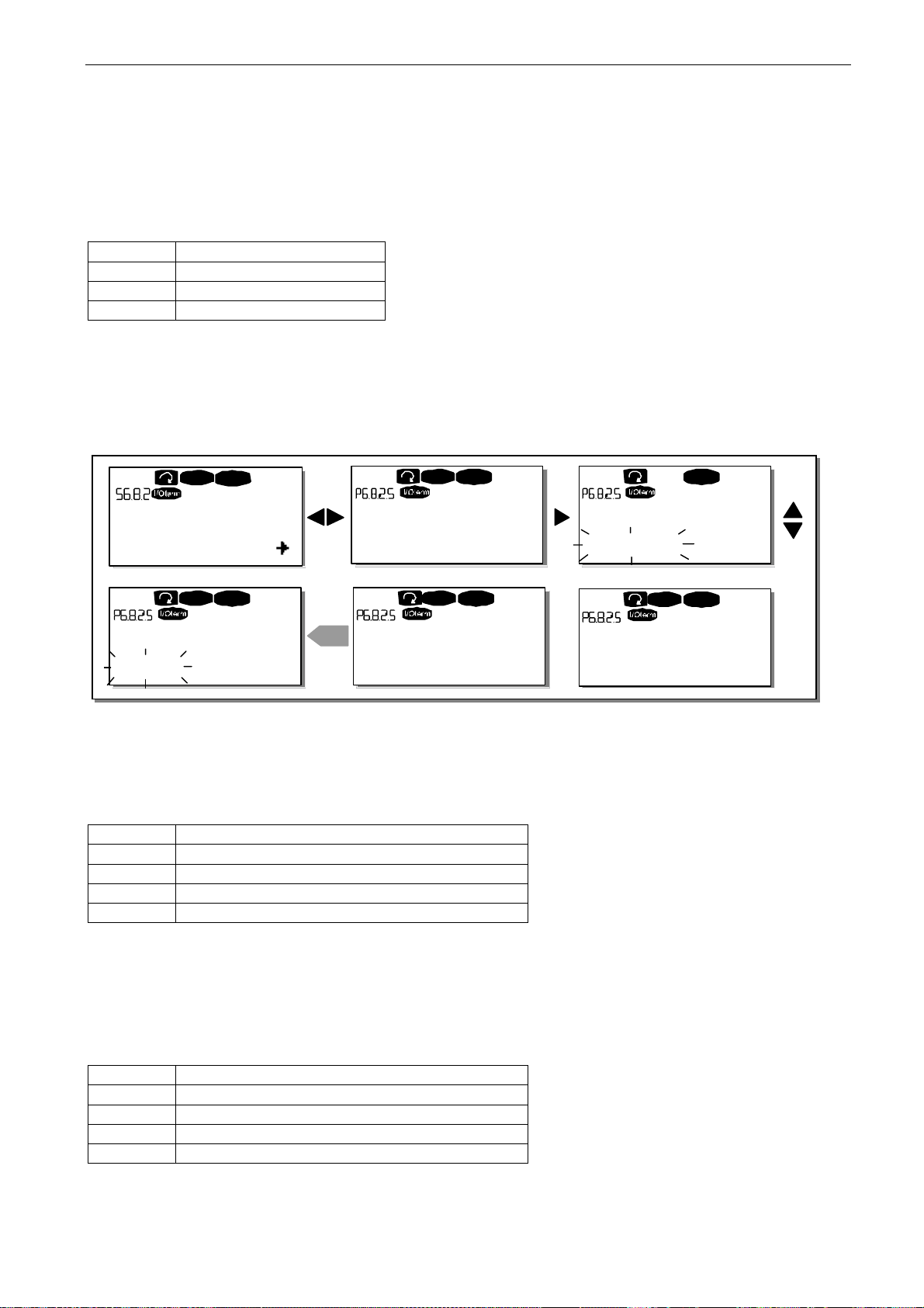
76 • vacon control keypad
Clearwater Tech - Phone: 800.894.0412 - Fax: 208.368.0415 - Web: www.clrwtr.com - Email: [email protected]
Trip counters
Trip counters
(menu S6.8.2) are counters the values of which can be reset i.e. restored to zero. You
can use the following resettable counters:
Note! The trip counters run only when the motor is running.
Page Counter
T6.8.2.1 MWh counter T6.8.2.3 Operation day counter T6.8.2.4 Operation hour counter
Table 7-6. Resettable counters
The counters can be reset on pages 6.8.2.2
counter)
.
(Clear MWh counter)
and 6.8.2.5
(Clear Operation time
Example: When you want to reset the operation counters you should do the following:
READY READY
READY
STOP
Trip counters
T1T5
READY READY
STOP STOP
Clr Optime cnt r
Reset
Figure 7-20. Counter reset
Software (S6.8.3)
The
Software
information page includes information on the following inverter software related
Clr Optime cntr Clr Optime cntr
Not reset Not reset
enter
Clr Optime cnt r
Reset
STOP
READYSTOP
Clr Optime cnt r
Not reset
topics:
Page Content
6.8.3.1 Software package
6.8.3.2 System software version
6.8.3.3 Firmware interface
6.8.3.4 System load
Table 7-7. Software information pages
Applications (S6.8.4)
At location S6.8.4, you can find the
Applications submenu
containing information on the application
currently in use and all other applications loaded into the inverter. The following information is
available:
Page Content
6.8.4.#
6.8.4.#.1 Application ID
6.8.4.#.2 Version
6.8.4.#.3 Firmware interface
Table 7-8. Applications information pages
Name of application
Tel: +358-201-2121 • Fax: +358-201-212 205
7
Page 78
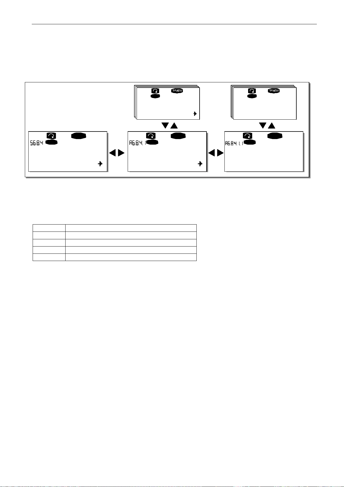
control keypad vacon • 77
Clearwater Tech - Phone: 800.894.0412 - Fax: 208.368.0415 - Web: www.clrwtr.com - Email: [email protected]
In the Applications information page, press
which there are as many as there are applications loaded into the inverter. Locate the desired
application with the
Use the
Browser buttons
I/Oterm I/Oterm
Browser buttons
to see the different pages.
READY READY
and then enter the Information pages with
Applications Basic
A1
Figure 7-21. Applications info submenu
Hardware (S6.8.5)
The
Hardware
Page Content
6.8.5.1 Nominal power of the unit
6.8.5.2 Nominal voltage of the unit
6.8.5.3 Brake chopper
6.8.5.4 Brake resistor
Table 7-9. Hardware information pages
A7
information page provides information on the following hardware-related topics:
Menu button right
I/Oterm
Standard
D1
D1
D3
D3
to enter the Application pages of
Menu button right
I/Oterm
Version
2.01
READY
I/Oterm
Application id
NXFIFF01
.
Expander boards (S6.8.6)
The
Expander boards submenu
Chapter 6.2)
You can check the status of each board slot by entering the Expander boards page with
right.
Use the
keypad will display the type of the expansion board and the text
connected to the slot the text
connection is lost for some reason, the text
Chapter 6.2, Figure 6-7.
For more information on expander board related parameters, see Chapter 7.3.7.
Browser buttons
contains information about the basic and option boards. (See
to view the status of each board slot. The description line of the
'Run'
is shown below it. If no board is
'no board'
will be shown. If a board is connected to a slot but the
'no conn.'
is displayed. For more information, see
Menu button
7
Page 79
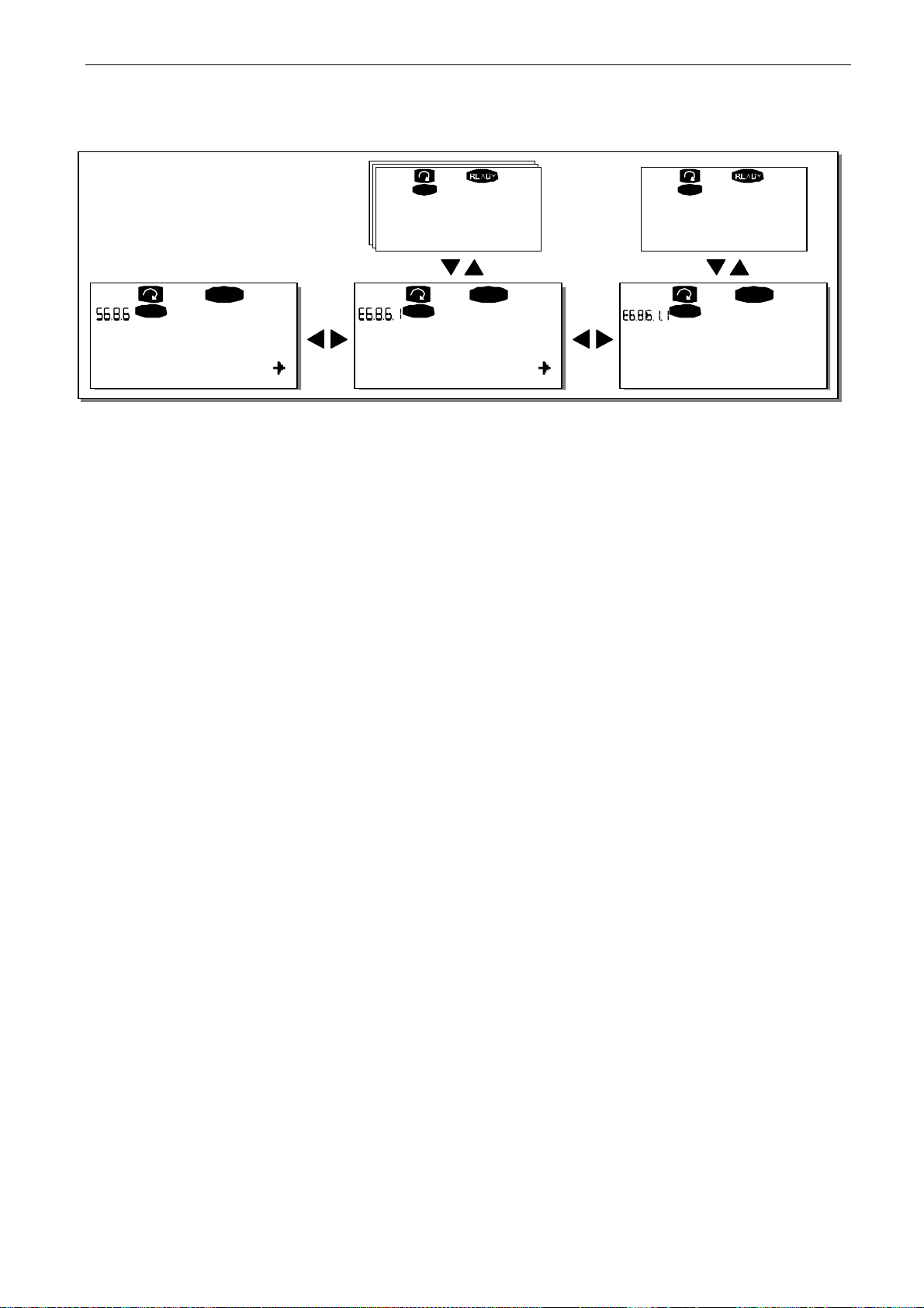
78 • vacon control keypad
Clearwater Tech - Phone: 800.894.0412 - Fax: 208.368.0415 - Web: www.clrwtr.com - Email: [email protected]
B:NXOPTA2
READY
I/Oterm
Expander boards
E1
Figure 7-22. Expander board information menus
E5
A:NXOPTA1
I/Oterm
I/Oterm
E1
E1
E2
READY
E2
I/Oterm
Soft wa r e versi on
10001.0
READY
I/Oterm
State
Run
Tel: +358-201-2121 • Fax: +358-201-212 205
7
Page 80
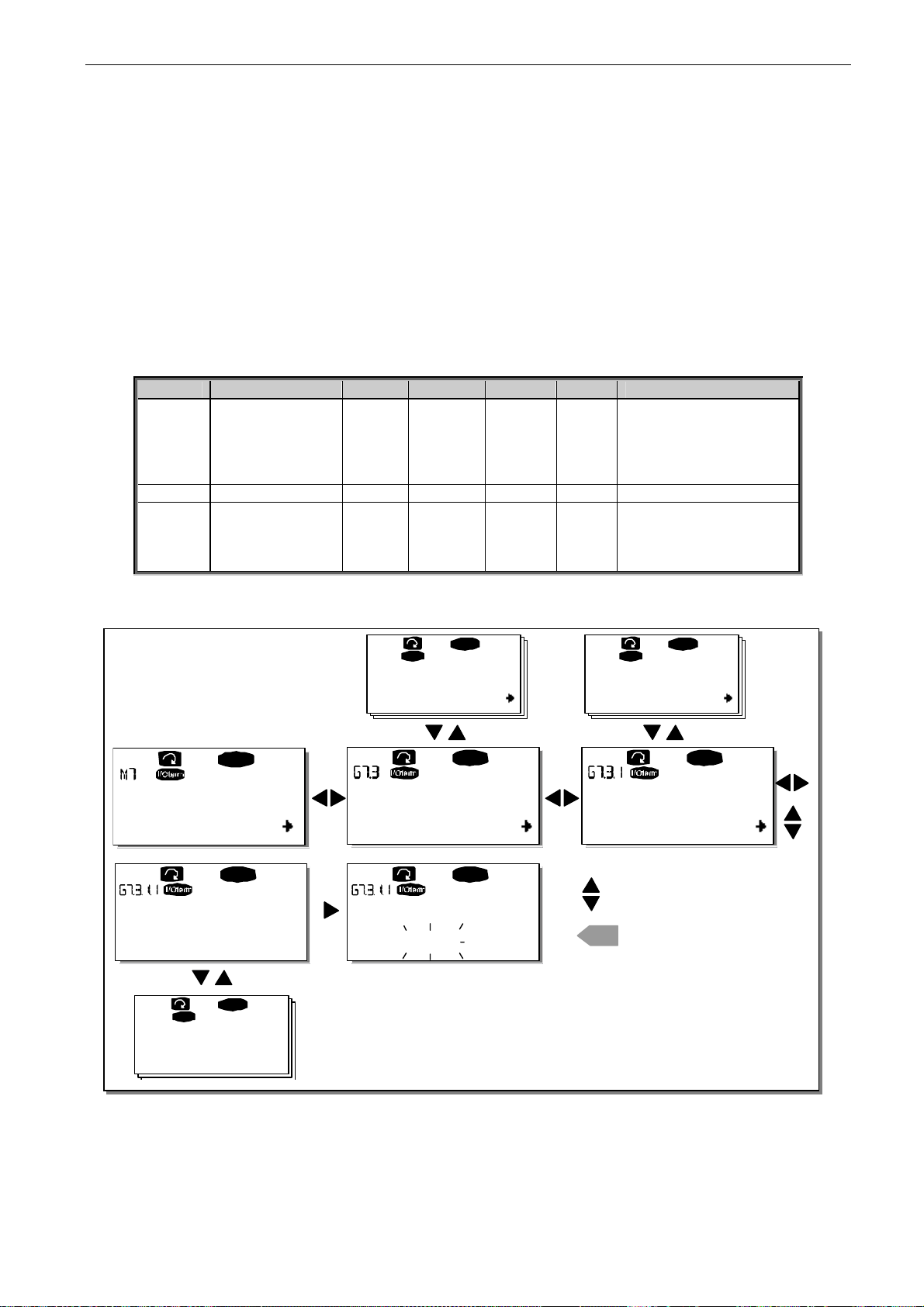
control keypad vacon • 79
Clearwater Tech - Phone: 800.894.0412 - Fax: 208.368.0415 - Web: www.clrwtr.com - Email: [email protected]
7.3.7 Expander board menu (M7)
In the
Expander board menu
the user can 1) see the expander boards connected to the control board
and 2) see and edit the parameters associated with the expander boards.
Go to the next menu level (G#) with
to E (see page 37) with the
Browser buttons
Menu button right
to see which expander boards are connected to the
. At this level, you can browse through slots A
control board. On the lowermost line of the display, you will also see the number of parameters
associated with the board. You can view and edit the parameter values as described in Chapter 7.3.2.
See Table 7-10 and Figure 7-23.
Expander board parameters
Code Parameter Min Max Default Cust Selections
1=0…20 mA 2=4…20 mA
P7.1.1.1 AI1 mode 1 5 3
P7.1.1.2 AI2 mode 1 5 1 See P7.1.1.1
P7.1.1.3 AO1 mode 1 4 1
3=0…10 V 4=2…10 V 5=–10…+10 V
1=0…20 mA 2=4…20 mA 3=0…10 V 4=2…10 V
Table 7-10. Expander board parameters (board NXOPTA1)
READY
Exp ande r boards
G1
G5
READY
Slave add res s
126
READY
I/Oterm
Baud rate
Auto
I/Ot erm
D:NXOPTC2
READY
G1G2
READY
C:NXOPTC1
G1G2
READY
Slave address
126
I/Ot erm
Monitor
READY
V1V2
Parameters
P1P4
CHANGE VALUE
CONFIRM CHANGE
enter
READY
Figure 7-23. Expander board information menu
7
Page 81

80 • vacon control keypad
Clearwater Tech - Phone: 800.894.0412 - Fax: 208.368.0415 - Web: www.clrwtr.com - Email: [email protected]
7.4 Further keypad functions
The Vacon NX control keypad contains additional application-related functions. See Vacon NX
Application Package for more information.
Tel: +358-201-2121 • Fax: +358-201-212 205
7
Page 82
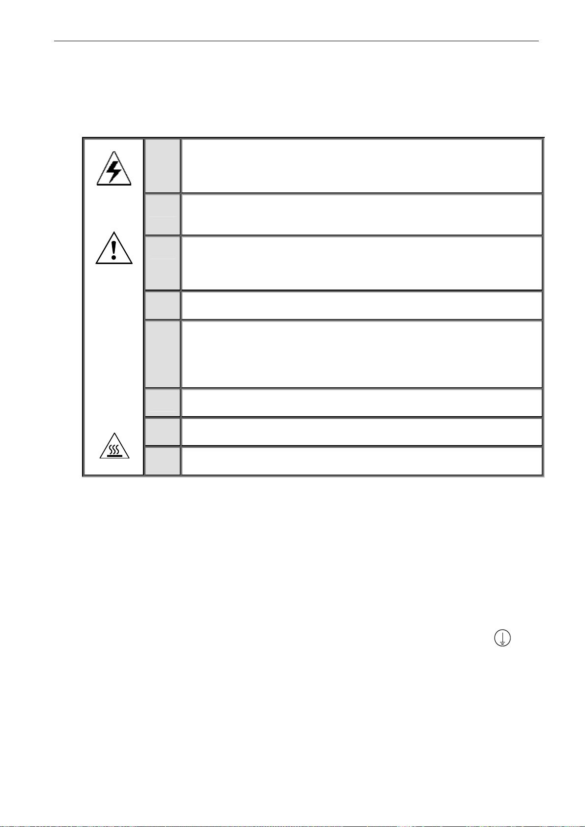
commissioning vacon • 81
Clearwater Tech - Phone: 800.894.0412 - Fax: 208.368.0415 - Web: www.clrwtr.com - Email: [email protected]
8. COMMISSIONING
8.1 Safety
Before commissioning, note the following directions and warnings:
WARNING
HOT SURFACE
8.2 Commissioning the inverter
Internal components and circuit boards of the inverter (except for the
1
galvanically isolated I/O terminals) are live when Vacon NX is connected
to mains potential. Coming into contact with this voltage is extremely
dangerous and may cause death or severe injury.
The motor terminals U, V, W and the DC-link/brake resistor terminals+/-
2
are live when Vacon NX inverter is connected to DC supply, even if the
motor is not running.
The control I/O-terminals are isolated from the mains potential.
3
However, the relay outputs and other I/O-terminals may have a
dangerous control voltage present even when Vacon NX is disconnected
from DC supply.
Do not make any connections when the inverter is connected to the DC
4
supply.
After having disconnected the inverter, wait until the fan stops and the
5
indicators on the keypad go out (if no keypad is attached see the indicator
through the keypad base). Wait 5 more minutes before doing any work on
Vacon NX connections. Do not open the cover before the time has
expired.
Before connecting the inverter to DC supply make sure that the Vacon NX
6
front cover is closed.
When running, the side of inverter FR8 is burning hot. Do not touch it with
7
bare hands!
When running, the back of inverter FR6 is burning hot. Therefore it MUST
8
NOT be mounted onto a surface which is not fireproof.
1 Read carefully the safety instructions in Chapter 1 and above and follow them. 2 After the installation, make sure that:
both the inverter and the motor are grounded
the DC supply and motor cables comply with the requirements given in Chapter 6.1.1.
the control cables are located as far as possible from the power cables (see Chapter 6.1.2,
step 2) and the shields of the shielded cables are connected to protective earth
wires may not touch the electrical components of the inverter.
the common inputs of digital input groups are connected to +24V or ground of the I/O
terminal or the external supply.
3 Check the quality and quantity of cooling air (See Chapter 5.2 and Table 5-6). 4 Check the inside of the inverter for condensation. 5 Check that all Start/Stop switches connected to the I/O terminals are in Stop position.
. The
8
Page 83

82 • vacon commissioning
Clearwater Tech - Phone: 800.894.0412 - Fax: 208.368.0415 - Web: www.clrwtr.com - Email: [email protected]
6 Connect the inverter to DC supply. 7 Set the parameters of group 1 according to the requirements of your application (See
Vacon All in One Application Manual). At least the following parameters should be set:
motor nominal voltage
motor nominal frequency
motor nominal speed
motor nominal current
You will find the values needed for the parameters on the motor rating plate.
8 Perform run test without motor
Perform either Test A or Test B:
A Controls from the I/O terminals:
Turn the Start/Stop switch to ON position.
Change the frequency reference (potentiometer)
Check in the Monitoring menu M1 that the value of Output frequency changes according to
the change of frequency reference.
Turn the Start/Stop switch to OFF position.
B Control from the control keypad:
Change the control from the I/O terminals to the keypad as advised in Chapter 7.3.3.1.
start
Press the START
button
on the keypad
.
Move over to the Keypad control menu M3 and Keypad Reference submenu (see Chapter
-
7.3.3.2 ) and change the frequency reference with the Browser buttons
Check in Monitoring menu M1 that the value of Output frequency changes according to the
change of frequency reference.
Press the STOP button on the keypad
stop
.
+
.
Tel: +358-201-2121 • Fax: +358-201-212 205
8
Page 84

commissioning vacon • 83
Clearwater Tech - Phone: 800.894.0412 - Fax: 208.368.0415 - Web: www.clrwtr.com - Email: [email protected]
9 Run the start-up tests without the motor being connected to the process. If this is not
possible, make sure that running each test is safe prior to running it. Inform your coworkers of the tests.
a)
Switch off the DC supply voltage and wait until the drive has stopped as advised in
Chapter 8.1, step 5.
b)
Connect the motor cable to the motor and to the motor cable terminals of the inverter.
c)
Make sure that all Start/Stop switches are in Stop positions.
d)
Switch the supply voltage ON
e)
Repeat test 8A or 8B.
10 Connect the motor to the process (if the start-up test was run without the motor being
connected)
a)
Before running the tests, make sure that this can be done safely.
b)
Inform your co-workers of the tests.
c)
Repeat test 8A or
8B.
8
Page 85
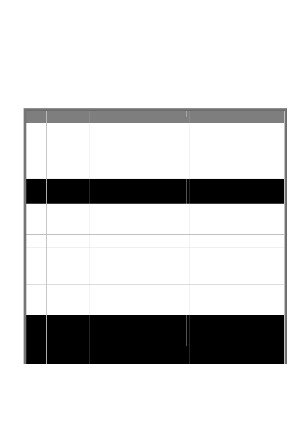
84 • vacon fault tracing
Clearwater Tech - Phone: 800.894.0412 - Fax: 208.368.0415 - Web: www.clrwtr.com - Email: [email protected]
9. FAULT TRACING
When a fault is detected by the inverter control electronics, the drive is stopped and the symbol F
together with the ordinal number of the fault, the fault code and a short fault description appear on
the display. The fault can be reset with the
The faults are stored in the Fault history menu M5, which can be browsed. The table below contains
all the fault codes.
The fault codes, their causes and correcting actions are presented in the table below. Shadowed
faults are A faults only. The items in white on black background present faults for which you can
program different responses in the application, see parameter group Protections.
reset
button on the control keypad or via the I/O terminal.
Fault
code
1 Overcurrent Inverter has detected too high a current
2 Overvoltage The DC-link voltage has exceeded the
3 Earth fault Current measurement has detected that
5 Charging switch The charging switch is open, when the
6 Emergency stop Stop signal has been given from the
7 Saturation trip Various causes:
8 System fault component failure
9 Undervoltage DC-link voltage is under the voltage limits
Fault Possible cause Correcting measures
) in the motor cable:
(>4*I
n
sudden heavy load increase
short circuit in motor cables
unsuitable motor
limits defined in Table 4-3.
too short a deceleration time
high overvoltage spikes in supply
the sum of motor phase current is not
zero.
insulation failure in cables or motor
START command has been given.
faulty operation
component failure
option board.
component failure
brake resistor short-circuit or overload
faulty operation
Note the exceptional Fault data record.
See 7.3.4.3.
defined in Table 4-3.
most probable cause: too low a supply
voltage
inverter internal fault
Check loading.
Check motor.
Check cables.
Set the deceleration time longer.
Add a brake chopper or a brake resistor.
Check motor cable and motor.
Reset the fault and restart.
Should the fault re-occur, contact the
distributor near to you.
Please visit:
http://www.vacon.com/wwcontacts.html
Cannot be reset from the keypad.
Switch off power.
DO NOT RE-CONNECT POWER!
Contact factory.
If this fault appears simultaneously with
Fault 1, check motor cables and motor
Reset the fault and restart.
Should the fault re-occur, contact the
distributor near to you.
Please visit:
http://www.vacon.com/wwcontacts.html
In case of temporary supply voltage
break reset the fault and restart the
inverter. Check the supply voltage. If it is
adequate, an internal failure has
occurred.
Contact the nearest Vacon distributor.
Please visit:
http://www.vacon.com/wwcontacts.html
Tel: +358-201-2121 • Fax: +358-201-212 205
9
Page 86
fault tracing vacon • 85
Clearwater Tech - Phone: 800.894.0412 - Fax: 208.368.0415 - Web: www.clrwtr.com - Email: [email protected]
10 Input line
supervision
11 Output phase
supervision
12 Brake chopper
supervision
13 Inverter
undertemperatu
re
14 Inverter
overtemperatur
e
15 Motor stalled Motor stall protection has tripped. Check motor. 16 Motor over-
temperature
17 Motor underload Motor underload protection has tripped.
22 EEPROM
checksum fault
24 Counter fault Values displayed on counters are
25 Microprocessor
watchdog fault
26 Start-up
prevented
29 Thermistor fault The thermistor input of option board has
31 IGBT
temperature
(hardware)
32 Fan cooling Cooling fan of the inverter does not start,
34 CAN bus
communication
36 Control unit NXS Control Unit can not control NXP
Input line phase is missing. Check supply voltage and cable.
Current measurement has detected that
there is no current in one motor phase.
no brake resistor installed
brake resistor is broken
brake chopper failure
Heatsink temperature is under –10°C
Heatsink temperature is over 90°C or
77ºC (NX_6, FR6).
Overtemperature warning is issued when
the heatsink temperature exceeds 85°C
(72ºC).
Motor overheating has been detected by
inverter motor temperature model. Motor
is overloaded.
Parameter save fault
faulty operation
component failure
incorrect
faulty operation
component failure
Start-up of the drive has been prevented. Cancel prevention of start-up.
detected increase of the motor
temperature
IGBT Inverter Bridge overtemperature
protection has detected too high a short
term overload current
when ON command is given
Sent message not acknowledged. Ensure that there is another device on
Power Unit and vice versa
Check motor cable and motor.
Check brake resistor.
If the resistor is ok, the chopper is
faulty. Contact the nearest Vacon
distributor.
Please visit:
http://www.vacon.com/wwcontacts.html
Check the correct amount and flow of
cooling air.
Check the heatsink for dust.
Check the ambient temperature.
Make sure that the switching frequency
is not too high in relation to ambient
temperature and motor load.
Decrease the motor load.
If no motor overload exists, check the
temperature model parameters.
Reset the fault and restart.
Should the fault re-occur, contact the
distributor near to you.
Please visit:
http://www.vacon.com/wwcontacts.html
Check motor cooling and loading
Check thermistor connection
(If thermistor input of the option board is
not in use it has to be short circuited)
Check loading.
Check motor size.
Contact the nearest Vacon distributor.
Please visit:
http://www.vacon.com/wwcontacts.html
the bus with the same configuration.
Change control unit
9
Page 87
86 • vacon fault tracing
Clearwater Tech - Phone: 800.894.0412 - Fax: 208.368.0415 - Web: www.clrwtr.com - Email: [email protected]
37 Device changed
(same type)
38 Device added
(same type)
39 Device removed Option board removed.
40 Device unknown Unknown option board or drive. Contact the nearest Vacon distributor.
41 IG BT temperature IGBT Inverter Bridge overtemperature
42 Brake resistor
overtemperature
43 Encoder fault Note the exceptional Fault data record.
44 Device changed
(different type)
45 Device added
(different type)
50 Analogue input
Iin < 4mA (sel.
signal range 4 to
20 mA)
51 External fault Digital input fault. 52 Keypad
communication
fault 53 Fieldbus fault The data connection between the fieldbus
54 Slot fault Defective option board or slot Check board and slot.
56 PT100 board
temp. fault
Option board or control unit changed.
Same type of board or same power rating
of drive.
Option board or drive added.
Drive of same power rating or same type
of board added.
Drive removed.
protection has detected too high a short
term overload current
Brake resistor overtemperature
protection has detected too heavy braking
See 7.3.4.3. Additional codes:
1 = Encoder 1 channel A is missing
2 = Encoder 1 channel B is missing
3 = Both encoder 1 channels are missing
4 = Encoder reversed
Option board or control unit changed.
Option board of different type or different
power rating of drive.
Option board or device added
Option board of different type or drive of
different power rating added.
Current at the analogue input is < 4mA.
control cable is broken or loose
signal source has failed
There is no connection between the
control keypad and the inverter.
Master and the fieldbus board is broken
Temperature limit values set for the
PT100 board parameters have been
exceeded
Reset
Note: No fault time data record!
Reset
Note: No fault time data record!
Reset
Note: No fault time data record!
Please visit:
http://www.vacon.com/wwcontacts.html
Check loading.
Check motor size.
Set the deceleration time longer.
Use external brake resistor.
Check encoder channel connections.
Check the encoder board.
Reset
Note: No fault time data record!
Note: Application parameter values
restored to default.
Reset
Note: No fault time data record!
Note: Application parameter values
restored to default.
Check the current loop circuitry.
Check keypad connection and possible keypad cable.
Check installation.
If installation is correct contact the
nearest Vacon distributor.
Please visit:
http://www.vacon.com/wwcontacts.html
Contact the nearest Vacon distributor.
Please visit:
http://www.vacon.com/wwcontacts.html
Find the cause of temperature rise
Table 9-1. Fault codes
Tel: +358-201-2121 • Fax: +358-201-212 205
9
 Loading...