

Vacon NXP Hardware Manual
vacon nxp
ac drives
liquid cooled enclosed solutions
hardware manual
®


vacon • 1
24-hour support +358 (0)201 212 575 • Email: vacon@vacon.com
Table 1. Manual revision history
Revision Release date Changes/updates
A 27.06.2014 First version

vacon • 2
Tel. +358 (0) 201 2121 • Fax +358 (0)201 212 205
TABLE OF CONTENTS
Document ID: DPD01596
Revision: A
Revision release date: 27.06.2014
1. Introduction ................................................................................................................ 4
1.1 Scope of supply ..................................................................................................................... 4
1.2 Related brochures and manuals........................................................................................... 4
1.3 Available drive sizes.............................................................................................................. 5
2. Enclosed solution sections.......................................................................................... 6
2.1 Incoming section ................................................................................................................... 7
2.2 Drive section.......................................................................................................................... 8
2.3 DU/DT and internal cooler section ....................................................................................... 9
2.4 Heat exchanger section.......................................................................................................10
3. Installation................................................................................................................ 11
3.1 Safety notes......................................................................................................................... 11
3.1.1 Danger................................................................................................................... 11
3.1.2 Warnings ............................................................................................................... 12
3.1.3 Earthing and earth fault protection ...................................................................... 13
3.2 Storage ................................................................................................................................ 14
3.3 Lifting and moving the cabinets.......................................................................................... 15
3.4 Fixing the cabinets .............................................................................................................. 16
3.4.1 Free space around the cabinet ............................................................................. 16
3.4.2 Fixing the cabinet to the floor or wall................................................................... 17
3.5 Cabling................................................................................................................................. 18
3.5.1 Earthing................................................................................................................. 18
3.5.2 Mains and motor connection ................................................................................ 18
3.5.3 Cooling pipe connections...................................................................................... 20
3.5.4 Control connections.............................................................................................. 21
3.6 Screw tightening torques.................................................................................................... 22
4. Service ...................................................................................................................... 23
4.1 Warranty.............................................................................................................................. 23
4.2 Proactive maintenance as recommended by manufacturer.............................................. 23
4.3 Replacement instructions................................................................................................... 27
4.3.1 Drives .................................................................................................................... 27
4.3.2 Fuses..................................................................................................................... 33
4.3.3 Cabinet fans for dU/dt and internal cooler........................................................... 34
4.3.4 Internal cooler ...................................................................................................... 36
5. Technical information ............................................................................................... 38
5.1 Control and interface .......................................................................................................... 38
5.1.1 Control without speed feedback (open loop)........................................................ 38
5.1.2 Control with speed feedback (closed loop) .......................................................... 38
5.2 Load definitions ................................................................................................................... 38
5.2.1 Pump and fan load ................................................................................................ 39
5.2.2 OL(
n
base
) > OL(
n
max
) for constant torque load ..................................................... 40
5.2.3 Starting torque >> OL(
n
max
) for constant torque load ......................................... 41
5.2.4 OL(
n
base
) > OL(
n
max
) for constant power load...................................................... 42
5.2.5 OL(
n
base
) < OL(
n
max
) for constant power load...................................................... 43
5.3 Technical specifications for VACON
®
NXP liquid cooled drives ........................................ 44
6. Supplied documentation ........................................................................................... 48
6.1 Documentation examples ................................................................................................... 49
6.1.1 Cable connection table ......................................................................................... 49
6.1.2 Parts list................................................................................................................ 50
6.1.3 Wiring list .............................................................................................................. 51
6.1.4 Circuit diagram ..................................................................................................... 52
6.1.5 Switchgear layout drawing ................................................................................... 53
6.1.6 Device layout drawing........................................................................................... 54

vacon • 3
24-hour support +358 (0)201 212 575 • Email: vacon@vacon.com
7. Appenix ..................................................................................................................... 55
7.1 Power line circuit diagram.................................................................................................. 55
7.2 P&ID drawings .................................................................................................................... 56

1
vacon • 4 Introduction
Tel. +358 (0) 201 2121 • Fax +358 (0)201 212 205
1. INTRODUCTION
The high power liquid cooled regenerative low harmonic enclosed solution is available in protection
degree IP54. The single NXP Ch64 enclosed solution can be used with AC motors in power sizes up
to 1550kW. The power range can be extended up to 5MW by using the innovative VACON DriveSync
control concept for running four Ch64 enclosed solutions in parallel.
The VACON
®
NXP is a state-of-the-art AC drive for use in all applications where robustness,
dynamic performance, precision and power are required. The Vacon NXP supports both induction
motors and permanent magnet motors in open and closed loop control modes. The VACON NXP also
supports special motors such as high speed motors.
1.1 Scope of supply
The scope of supply is limited to the drives listed in this manual. Process, machine or drive control
systems are not part of Vacon Plc’s scope of supply.
1.2 Related brochures and manuals
All Vacon user manuals and brochures are available in PDF format on the Vacon website at
www.vacon.com/downloads/.
Also manuals for different applications and option boards are available on the Vacon website at
www.vacon.com/downloads/.
Table 2. Related user manuals and brochures
Document ID Name of manual
BC00054 VACON NXP Liquid Cooled Brochure
DPD00887 VACON NXP Liquid Cooled User manual
UD01149 VACON NXP HXL120 Cooling Unit Installation Manual
DPD01308 VACON NXP HXM120 Cooling Unit Installation Manual
Introduction vacon • 5
24-hour support +358 (0)201 212 575 • Email: vacon@vacon.com
1
1.3 Available drive sizes
VACON® NXP liquid cooled enclosed solutions are available in the voltage ranges 400-500VAC and
525-690V
AC
. The available drive sizes are listed below.
Table 3. Technical data for available drive sizes
Supply
voltage
[V
AC
]
AC drive
type
Drive/current
Electrical output
power
Chassis
Dimensions
WxHxD without
cooling skid
[mm]
Thermal
Chassis
I
TH
[A]
Rated Optimum
Cont.
I
L
[A]
Cont.
I
H
[A]
Motor at
I
TH
(525V
AC
)
[kW]
Motor at
I
TH
(690V
AC
)
[kW]
400-500
1370_5 1375 1245 913 700 900 Ch64 2000x2100x900
1640_5 1640 1491 1093 900 1100 Ch64 2000x2100x900
525-690
0820_6 820 745 547 560 800 Ch64 2000x2100x900
0920_6 920 836 613 650 850 Ch64 2000x2100x900
1030_6 1030 936 687 700 1000 Ch64 2000x2100x900
1180_6 1180 1073 787 800 1100 Ch64 2000x2100x900
1300_6 1300 1182 867 900 1200 Ch64 2000x2100x900
1500_6 1500 1364 1000 1000 1400 Ch64 2000x2100x900
1700_6 1700 1545 1133 1150 1550 Ch64 2000x2100x900
2
vacon • 6 Enclosed solution sections
Tel. +358 (0) 201 2121 • Fax +358 (0)201 212 205
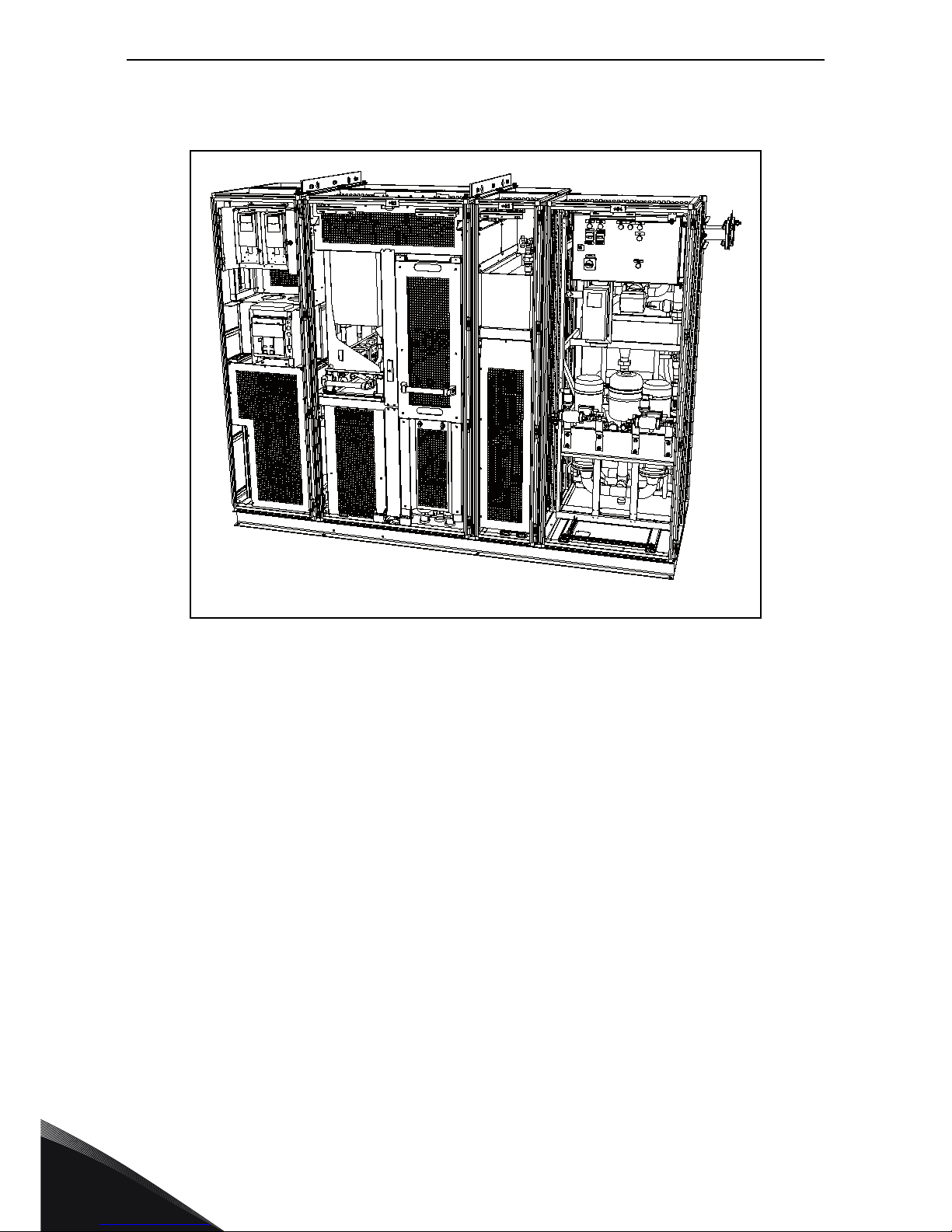
2. ENCLOSED SOLUTION SECTIONS
Figure 1. NXP liquid cooled enclosed solutions sections
NXP Liquid cooled enclosed solutions includes the following sections:
• +01: Incoming section
• +02: Drive section
• +03: DU/dt and internal cooler section
• +04: Heat exchanger section (optional)
NOTE! The enclosed solution is also available as a mirror image. The section order shown above is
the standard.
+01
+02
+03
+04
Enclosed solution sections vacon • 7
24-hour support +358 (0)201 212 575 • Email: vacon@vacon.com
2
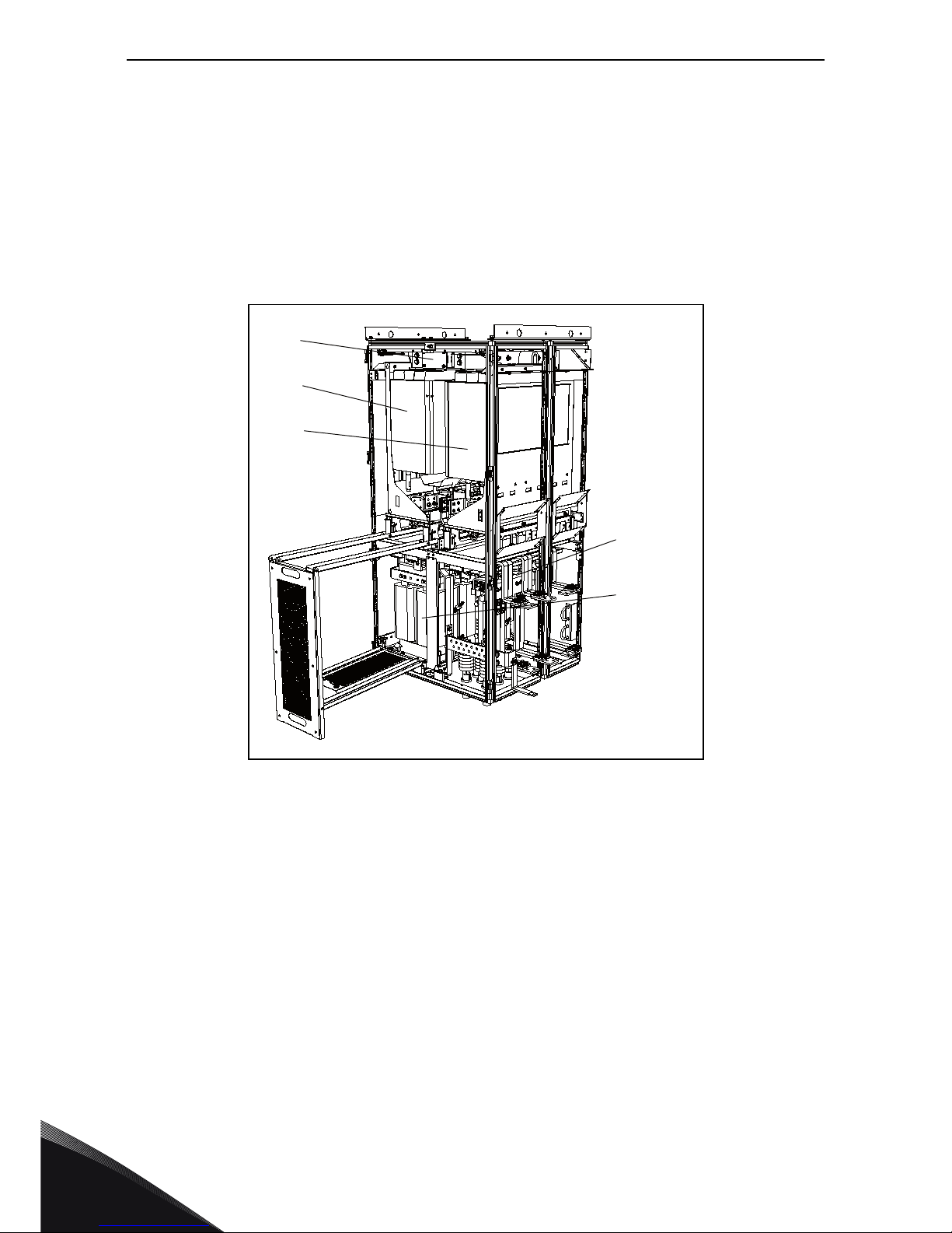
2.1 Incoming section
The incoming section includes the mains connection, circuit breaker, LCL and control equipment.
As standard the incoming section has the following equipment:
-Q1: Main circuit breaker
-TR1: Control voltage transformer
-U1: AFE control module
-U2: INU control module
-C1: LCL capacitor
-F1: AC fuses
-L1: LCL
-V3, V4: Cooling fans
-X1...: Terminal blocks
>L1,>L2,>L3: Mains connection L1, L2, L3
Figure 2. Incoming section
-TR1
-C1
-L1
-F1
-U2
-U1
-Q1
>L1
>L2
>L3
-X1...
-V3,V4
2
vacon • 8 Enclosed solution sections
Tel. +358 (0) 201 2121 • Fax +358 (0)201 212 205
2.2 Drive section
The drive section includes the VACON® NXP liquid cooled AFE and INU modules.
As standard the section includes the following:
-U1: AFE power module
-U2: INU power module
-F2: DC fuses
-L2: LCL
>U, >V, >W: Motor connection
Figure 3. Drive section
-U1
-F2
-U2
-L2
>U
>V
>W
Enclosed solution sections vacon • 9
24-hour support +358 (0)201 212 575 • Email: vacon@vacon.com
2
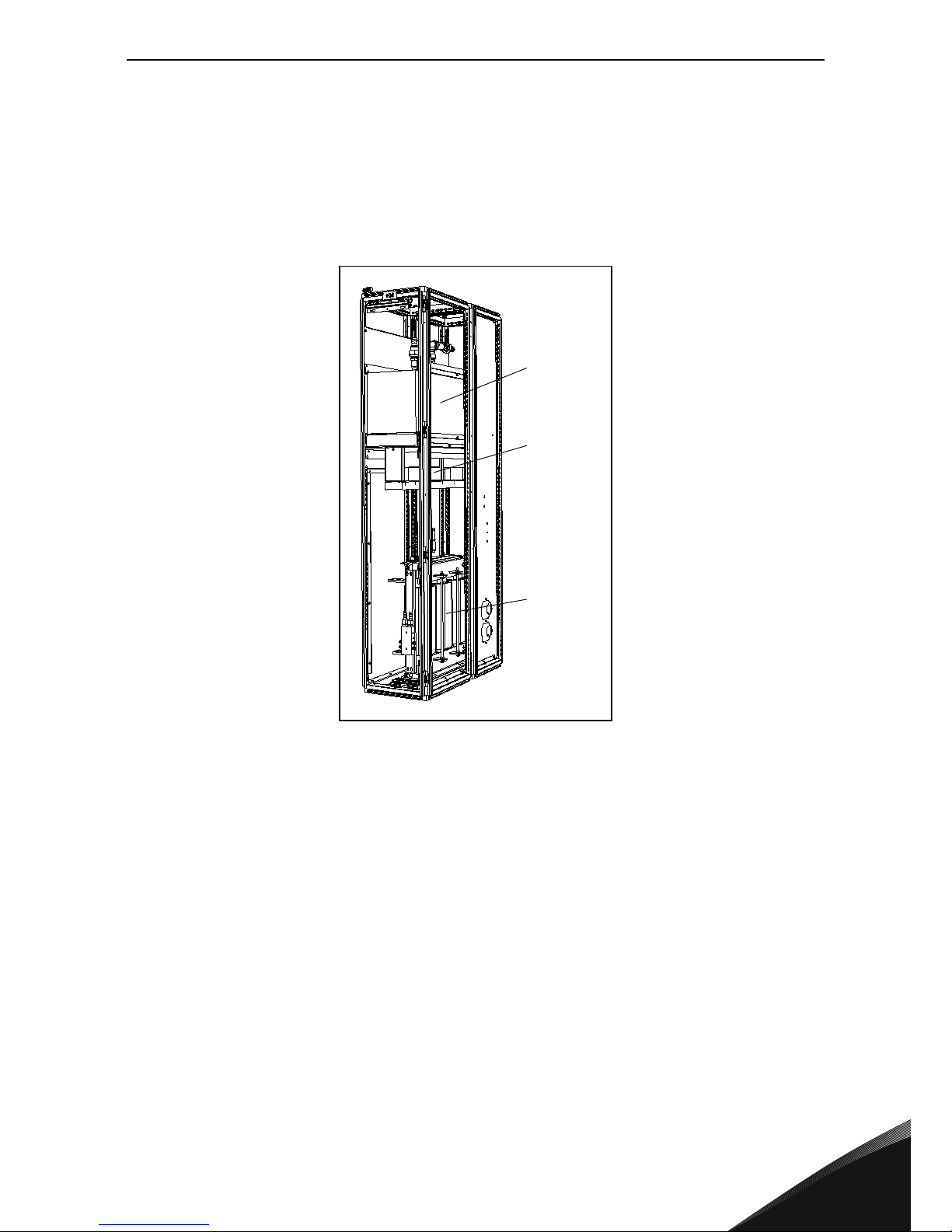
2.3 DU/DT and internal cooler section
This section includes a dU/dt filter and an internal cooler.
As standard the section includes the following:
-COOL1: Internal cooler
-V1,V2: Cooling fans
-L3: dU/dt filter
Figure 4. DU/DT and internal cooler section
-V1,V2
-COOL1
-L3
2
vacon • 10 Enclosed solution sections
Tel. +358 (0) 201 2121 • Fax +358 (0)201 212 205
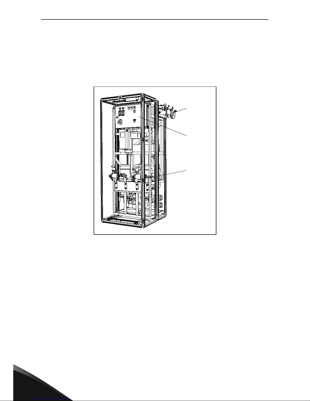
2.4 Heat exchanger section
The section includes a VACON® HXL/HXM 120 heat exchanger. This section is available as an option.
As standard the section includes the following:
-HEX1: Heat exchanger, HXL/HXM
-IN, OUT: DN50 flanges DIN2642, coolant in/out
-CTRL: Heat exchanger control unit
Figure 5. Heat exchanger section
-CTRL
-HEX1
-IN, OUT
Installation vacon • 11
24-hour support +358 (0)201 212 575 • Email: vacon@vacon.com
3
3. INSTALLATION
3.1 Safety notes
Please, read the information in cautions and warnings carefully.
The cautions and warnings are marked as follows:
3.1.1 Danger
NOTE! You can download the English and French product manuals with applicable safety,
warning and caution information from www.vacon.com/downloads.
REMARQUE Vous pouvez télécharger les versions anglaise et française des manuels produit
contenant l’ensemble des informations de sécurité, avertissements et mises en garde
applicables sur le site www.vacon.com/downloads.
= DANGEROUS VOLTAGE!
= GENERAL WARNING!
Only a competent electrician may carry out the electrical installation!
The components of the power unit and all cabinet mounted devices are live when
the drive is connected to mains potential. Coming into contact with this voltage is
extremely dangerous and may cause death or severe injury.
The motor terminals U, V, W, the DC bus/brake resistor terminals and all other
mains devices are potentially live when the drive is connected to mains, even if the
motor is not running.
After disconnecting the AC drive from the mains, wait until the fan stops and the
indicators on the keypad go out (if no keypad is attached see the indicators on the
cover). Wait 5 more minutes before doing any work on the connections of the drive. Do
not open the cabinet door before this time has expired. After expiration of this time,
use measuring equipment to absolutely ensure that no voltage is present. Always
ensure the absence of voltage before starting any electrical work!
The control I/O-terminals are isolated from the mains potential. However, the relay
outputs and other I/O-terminals may have a dangerous control voltage present even
when the drive is disconnected from mains.
Before connecting the drive to mains make sure that the drive front and cable covers
as well as the cabinet doors are closed.
9000.emf
13006.emf
13006.emf
9000.emf
9000.emf
9000.emf
9000.emf
9000.emf
3
vacon • 12 Installation
Tel. +358 (0) 201 2121 • Fax +358 (0)201 212 205
3.1.2 Warnings
Before connecting the drive to mains ensure the functionality of the coolant
circulation and check the circulation for possible leaks.
If the AC drive is disconnected from mains while running the motor, it remains live if
the motor is energized by the process. In this case the motor functions as a generator
feeding energy to the AC drive.
Vacon drives are meant for
fixed installations only
.
Do not perform any measurements when the AC drive is connected to mains.
The touch current of Vacon AC drives exceeds 3.5 mA
AC
. According to standard
EN61800-5-1, a reinforced protective ground connection must be ensured. See
Chapter 3.1.3.
If the drive is used as a part of a machine, the machine manufacturer is responsible
for providing the machine with a supply disconnecting device (EN60204-1).
Only spare parts delivered by Vacon can be used.
At power-up, power brake or fault reset the motor will start immediately if the start
signal is active, unless the pulse control for Start/Stop logic has been selected.
Futhermore, the I/O functionalities (including start inputs) may change if parameters,
applications or software are changed. Disconnect, therefore, the motor if an
unexpected start can cause danger.
The motor starts automatically after automatic fault reset if the autoreset function is
activated. See the Application Manual for more detailed information.
Prior to measurements on the motor or the motor cable, disconnect the motor cable
from the drive.
Do not touch the components on the circuit boards. Static voltage disharge may
damage the components.
Check that the EMC level of the AC drive corresponds to the requirements of the
supply network.
Do not lift the AC drive from the plastic handles with an elevating device, such as jib
crane or hoist.
9000.emf
9000.emf
13006.emf
13006.emf
13006.emf
13006.emf
13006.emf
13006.emf
13006.emf
13006.emf
13006.emf
13006.emf
13006.emf
Installation vacon • 13
24-hour support +358 (0)201 212 575 • Email: vacon@vacon.com
3
3.1.3 Earthing and earth fault protection
The AC drive must always be earthed with an earthing conductor connected to the earthing terminal
marked with:
The touch current of the AC drive exceeds 3.5 mA
AC
. According to EN61800-5-1, one or more of the
following conditions for the associated protective circuit shall be satisfied:
A fixed connection and
•the protective earthing conductor shall have a cross-sectional area of at least 10 mm
2
Cu
or 16 mm
2
Al, or
• an automatic disconnection of the supply in case of discontinuity of the protective earthing
conductor, or
• provision of an additional terminal for a second protective earthing conductor of the same
cross-sectional area as the original protective earthing conductor.
The cross-sectional area of every protective earthing conductor which does not form part of the
supply cable enclosure shall, in any case, be no less than:
•2.5 mm
2
if mechanical protection is provided or
•4 mm
2
if mechanical protection is not provided. For cord-connected equipment, provisions
shall be made so that the protective earthing conductor in the cord shall, in the case of
failure of the strain-relief mechanism, be the last conductor to be interrupted.
However, always follow the local regulations for the minimum size of the protective earthing conductor.
NOTE! Due to the high capacitive currents present in the AC drive, fault current protective switches
may not function properly.
CAUTION!
Table 4. Protective earthing conductor cross-section
Cross-sectional area of phase conductors (S)
[mm
2
]
Minimum cross-sectional area of the corre-
sponding protective earthing conductor [mm2]
S
≤16
16<
S
≤35
35<
S
S
16
S
/2
The values above are valid only if the protective earthing conductor is made of the same metal as
the phase conductors. If this is not so, the cross-sectional area of the protective earthing
conductor shall be determined in a manner which produces a conductance equivalent to that
which results from the application of this table.
Do not perform any voltage withstand tests on any part of the AC drive. There is a
certain procedure according to which the test shall be performed. Ignoring this
procedure may result in a damaged product.
13006.emf
13006.emf
3
vacon • 14 Installation
Tel. +358 (0) 201 2121 • Fax +358 (0)201 212 205
3.2 Storage
If the frequency converter is to be kept in store before use, make sure that the ambient conditions
are acceptable:
• Storing temperature –40…+70°C (no cooling liquid inside cooling element allowed below
0ºC)
• Relative humidity <96%, no condensation
The environment should also be free from dust. If there is dust in the air, the converter should be
well protected to make sure dust does not get into the converter.
If the converter is to be stored during longer periods, the power should be connected to the
converter once in 24 months and kept on for at least 2 hours. If the storage time exceeds 24 months
the electrolytic DC capacitors need to be charged with caution. Therefore, such a long storage time
is not recommended.
If the storing time is much longer than 24 months, the recharging of the capacitors has to be carried
out so that the possible high leakage current through the capacitors is limited. The best alternative
is to use a DC power supply with adjustable current limit. The current limit has to be set for example
to 300-500mA and the DC power supply has to be connected to the B+/B- terminals (DC supply
terminals).
DC voltage must be adjusted to nominal DC voltage level of the unit (1.35xU
n AC
) and supplied at
least for 1 hour.
If DC voltage is not available and the unit has been stored de-energized much longer than 1 year,
consult factory before connecting power.
Always remove all cooling agent from the cooling element(s) before shipping to avoid
damage caused by freezing.
13006.emf
Installation vacon • 15
24-hour support +358 (0)201 212 575 • Email: vacon@vacon.com
3
3.3 Lifting and moving the cabinets
The cabinets are delivered either in a wooden box or a wooden cage. The boxes should be
transported vertically. Transportation in a horizontal position is not allowed. Always refer to
shipping marks for more detailed information. To lift the cabinets out of the box, use lifting
equipment capable of handling the weight of the cabinets.
There are lifting lugs on the top of the cabinets and these lugs can be used to lift the cabinet into an
upright position and to move it to the place needed.
Figure 6. Lifting the cabinets
Moving of the cabinets on site can be carried out as follows by a forklift truck, a hoist or on rollers:
• Lower the package onto a level base
• Remove the package covering only at the site of installation
• Low, narrow or convoluted transport routes may require removal of the pallet prior to
movement
• Move packages in the upright position only
Figure 7. Moving the cabinets
Switchgear parts can easily topple backwards when manoeuvring on rollers or
manual trolleys because their centre of gravity is typically located high up at the rear
of the unit.
Min 60°
13006.emf
3
vacon • 16 Installation
Tel. +358 (0) 201 2121 • Fax +358 (0)201 212 205
3.4 Fixing the cabinets
Before starting the installation work make sure that the level of the floor is within acceptable limits.
The maximum deviation from the basic level can be no more than 5 mm over a 3 m distance. The
maximum acceptable height difference between cabinet front and rear edges should be within
+2/-0 mm limit.
The cabinet should always be fixed to the floor or to the wall. Depending on installation conditions,
the cabinet sections can be fixed in different ways. There are holes in the front corners which can
be used for fixing. Additionally, the rails on the top of the cabinet have fixing lugs for fixing the
cabinet to the wall.
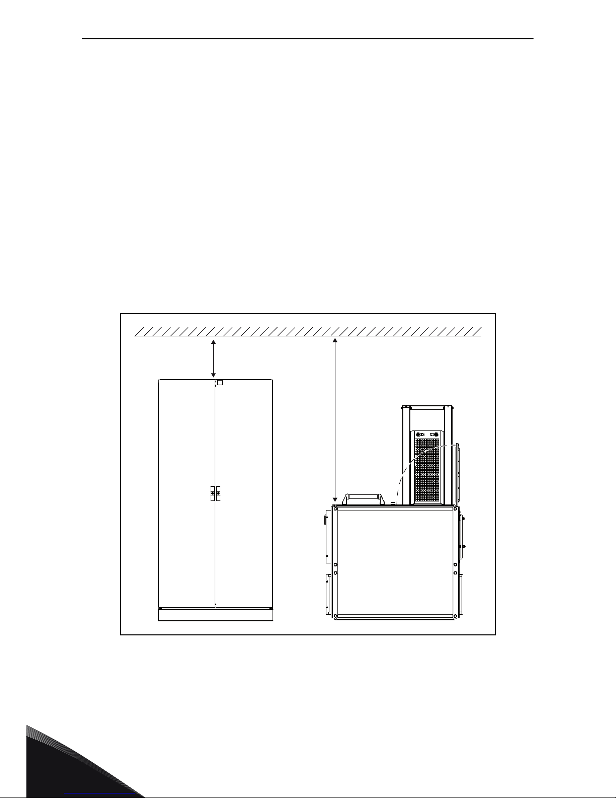
3.4.1 Free space around the cabinet
Enough space must be left above and in front of the cabinet to ensure sufficient cooling and space
for maintenance.
It is recommended to leave at least 100 mm above and 1200 mm in front of the cabinets.
Also make sure that the temperature of the cooling air does not exceed the maximum ambient
temperature of the drives.
Figure 8. Required space around the cabinet
100 mm
1200 mm
 Loading...