

Page 1

vacon nx
ac drives
optc6
canopen option board
user manual
Page 2

INDEX
1.
GENERAL ........................................................................................................................... 3
2.
CANOPEN OPTION BOARD TECHNICAL DATA .................................................................... 4
3.
CANOPEN ........................................................................................................................... 5
4.
CANOPEN OPTION BOARD LAYOUT AND CONNECTIONS .................................................. 6
5.
INSTALLATION OF VACON NX CANOPEN BOARD ............................................................. 13
6.
COMMISSIONING .............................................................................................................. 16
7.
CANOPEN-VACON NX INTERFACE ................................................................................... 19
8.
Service Data (SDO) ........................................................................................................... 31
9.
Node Guarding Protocol ................................................................................................... 42
10.
Electronic Data Sheet, EDS-file ....................................................................................... 43
11.
APPENDICES .................................................................................................................... 44
Document code: DPD00896A
Date: 17.01.2012
2.1 General ..................................................................................................................................... 4
2.2 CanOpen cable .......................................................................................................................... 4
4.1 CanOpen option board .............................................................................................................. 6
4.2 Bus terminal resistors ............................................................................................................. 6
4.3 LED indications ......................................................................................................................... 7
4.4 Connection of CanOpen bus cable ............................................................................................ 8
5.1 Board information sticker ...................................................................................................... 15
7.1 CanOpen message frame ....................................................................................................... 19
7.2 Network Management (NMT) ................................................................................................. 21
7.3 Process data (PDO) ................................................................................................................. 22
7.4 Transmission types ................................................................................................................ 23
7.5 Controlling the drive via PDO messages with Drive Profile ................................................... 24
7.6 Using manufacturer specific PDOs with ByPass modes ........................................................ 27
7.7 Drive Monitoring ..................................................................................................................... 29
7.8 Anyparameter service ............................................................................................................ 30
appendix a - device profile for drives ..................................................................................................... 44
appendix b – sdo messages .................................................................................................................... 45
appendix c – process data contents ....................................................................................................... 46
appendix d .............................................................................................................................................. 47
Tel.+358 (0)201 2121 • Fax +358 (0)201 212 205
Page 3
general vacon • 3
1
1. GENERAL
DANGER
NOTE!
Fieldbus@vacon.com.
Vacon NX frequency converters can be connected to the CanOpen system using a fieldbus board. The
converter can then be controlled, monitored and programmed from the Host system.
The CanOpen fieldbus board shall be installed in slot E on the control board of the frequency
converter.
Internal components and circuit boards are at high potential when the frequency
converter is connected to the power source. This voltage is extremely dangerous
and may cause death or severe injury if you come into contact with it.
When experiencing problems with fieldbus functionalities, please contact
NOTE! You can download the English and French product manuals with applicable safety,
warning and caution information from www.vacon.com/downloads
REMARQUE Vous pouvez télécharger les versions anglaise et française des manuels produit
contenant l’ensemble des informations de sécurité, avertissements et mises en garde
applicables sur le site www.vacon.com/downloads
.
.
24-hour support +358 (0)40 837 1150 • Email: vacon@vacon.com
Page 4
4 • vacon canopen
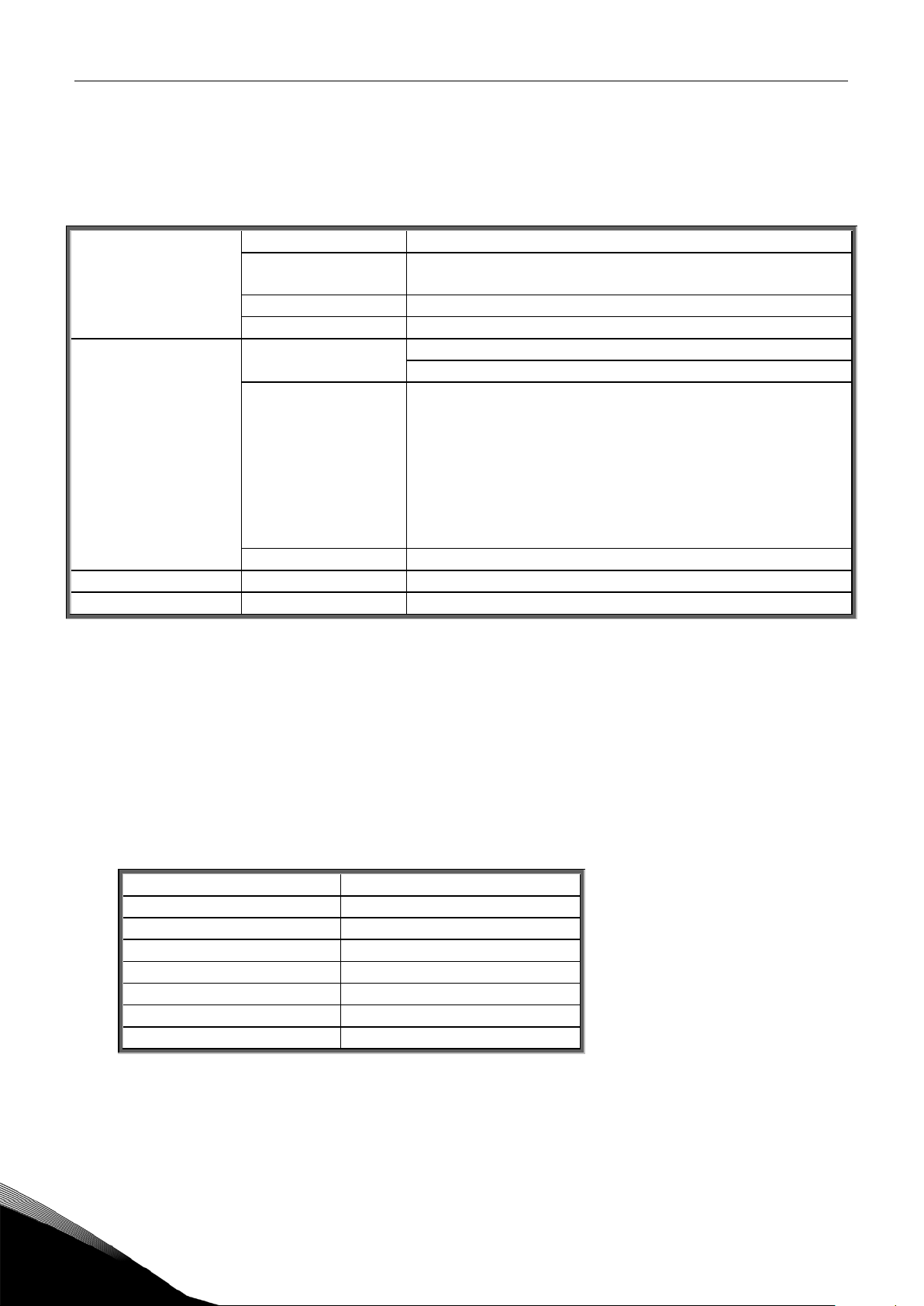
2. CANOPEN OPTION BOARD TECHNICAL DATA
2.1 General
2.2 CanOpen cable
Baudrate [Kbit/s]
Max. Bus length [m]
30
CanOpen
connections
Communications CanOpen CiA DS-301
Environment The specifications of the drive are applicable.
Safety Fulfils EN50178 standard
Table 2-1. CanOpen technical data
Interface Open Style Connector (Pluggable connector, 5.08mm)
Data transfer
method
Transfer cable 2 wire twisted shielded cable
Electrical isolation 500 VDC
Baud rate 10 kBaud
Addresses 1 – 127
CAN (ISO 11898)
CiA DSP-402
20 kBaud
50 kBaud
100 kBaud
125 kBaud
250 kBaud
500 kBaud
1000 kBaud
According to the ISO 11898 standard, cables to be chosen for CAN bus lines should have a nominal
impedance of 120Ω, and a specific line delay of nominal 5 ns/m. Line termination has to be provided
through termination resistors of 120Ω located at both ends of the line. The length related resistance
should have 70 mΩ/m. All these mentioned AC and DC parameters are suitable for a 1 Mbit/s
transmission rate.
The table below shows practical bus length for CANopen networks with less than 64 nodes:
1000
800 50
500 100
250 250
125 500
50 1000
20 2500
Tel.+358-(0)201-21 Tel. +358 (0)201 2121 • Fax +358 (0)201 212 205
3
Page 5

CanOpen Option Board Vacon • 5
3. CANOPEN
Velocity Mode
CANopen is a networking system based on the serial bus Controller Area Network (CAN). The
CANopen Communication Profile (CiA DS-301) supports both direct access to device parameters and
time-critical process data communication. CANopen device profiles (CiA DS-40x) define standards for
basic device functionality while providing ample scope for additional vendor-specific device features.
CANopen leashes the full power of CAN by allowing direct peer to peer data exchange between nodes
in an organised and, if necessary, deterministic manner. The network management functions
specified in CANopen simplify project design, implementation and diagnosis by providing standard
mechanisms for network start-up and error management.
CANopen supports both-cyclic and event-driven communication. This makes it possible to reduce the
bus load to a minimum but still maintaining extremely short reaction times. High communication
performance can be achieved at relatively low baud rates, thus reducing EMC problems and
minimising cable costs.
CANopen is the ideal networking system for all types of automated machinery. One of the
distinguishing features of CANopen is its support for data exchange at the supervisory control level as
well as accommodating the integration of very small sensors and actuators on the same physical
network. This avoids the unnecessary expense of gateways linking sensor/actuator bus systems with
higher communication networks and makes CANopen particularly attractive to original equipment
manufacturers.
Device Profile Drives and Motion Control (CiA DSP-402)
document represents the standardised
CANopen Device Profile for digital controlled motion products like servo controllers, frequency
converters or stepper motors. All the above-mentioned devices use communication techniques which
conform to those described in the CANopen Application Layer and Communication Profile. The
starting and stopping of the drive and several mode specific commands are executed by the
statemachine. The operation mode defines the behaviour of the drive. The following modes are
defined in this profile:
Homing Mode
Profile Position Mode
Interpolated Position Mode
Profile Velocity Mode
Profile Torque Mode
Velocity Mode
Vacon CanOpen Option Board supports the
24-hour support +358 (0)40 837 1150 • Email: vacon@vacon.com
Page 6

6 • vacon installation
4. CANOPEN OPTION BOARD LAYOUT AND CONNECTIONS
4.1 CanOpen option board
Signal
Connector
Description
CAN_L
2
CAN_L bus line (dominant low)
4.2 Bus terminal resistors
X1
A
M
X6
Jumpers
Interface board
connector
Grounding plate
Bus connector
1
2
3
4
5
Vacon CanOpen Board is connected to the fieldbus through a 5-pin pluggable bus connector (board
NXOPTC6).
The communication with the control board of the frequency converter takes place through the
standard Vacon Interface Board Connector.
Figure 4-1. Vacon CanOpen option board OPT-C6
CAN_GND 1 Ground / 0V / V-
(CAN_SHLD) 3 Optional CAN shield
CAN_H 4 CAN_H bus line (dominant high)
(CAN_V+) 5 -
Table 4-1.OPT-C6 bus connector signals
If Vacon drive is the last device of the CanOpen line the bus termination must be set. Use jumper X6
(ON position see Figure 4-1), or an external resistor (120Ω) connected to terminals 2 and 4.
ON OFF
Tel.+358-(0)201-21 Tel. +358 (0)201 2121 • Fax +358 (0)201 212 205
5
Page 7

installation Vacon • 7
4.3 LED indications
CanOpen board status LED (A) GREEN
OFF
Option board not activated
X1
A
M
X6
N
Green
Green
Not used
1
2
3
4
5
The CanOpen Option Board includes two LED status indicators next to the connector: Fieldbus status
(M), CanOpen(A). Led N is unused.
Figure 4-2. LED indications on the CANopen board
LED is: Meaning:
ON Option board in initialisation state waiting for activation
command from the frequency converter
Blinking fast
(1 blink / s)
Blinking slow
(1 blink/ 5s)
Fieldbus status LED (M) GREEN
LED is: Meaning:
OFF Fieldbus module is waiting for parameters from the
ON Fieldbus module is activated
Blinking fast
(1 blink / s)
Blinking slow
(1 blink / 5s)
Option board is activated and in RUN state
Option board is ready for external communication
Option board is activated and in FAULT state
Internal fault of option board
frequency converter
No external communication
Parameters received and module activated
Module is waiting for messages from the bus
Module is activated and receiving messages from the bus
Module is in FAULT state
No messages from Master within the watchdog time
Bus broken, cable loose or Master off line
24-hour support +358 (0)40 837 1150 • Email: vacon@vacon.com
5
Page 8

8 • vacon installation
4.4 Connection of CanOpen bus cable
Note:
Grounding by clamping the cable to the converter frame
cut off the
grey cable shield
Note:
of both CanOpen cables
Error! Reference source not found.
c a b l e
c a b l e
c a b l e
C a n p e n O C a n p e n
O
O
The bus cable shield can be grounded in three different ways:
a) clamping the cable to the frequency converter frame
b) to the frame of the frequency converter through an RC filter
c) directly to the converter frame
Normally, the option board has already been installed in slot E of the control board. It is not
necessary to detach the whole board for the grounding of the bus cable shield. Just detach the
terminal block.
4.4.1
This manner of grounding is the most effective and especially recommended when the distances
between the devices are relatively short (see 4.4.2.1).
In this manner of grounding, the position of jumper X1 is of no importance
Figure 4-3. Grounding by clamping the cable to the converter frame
C a n p e n
1 Strip about 5 cm of the CanOpen cable in the same way as shown in Figure 4-4 but
.
Remember to do this for both bus cables (except for the last device).
2 Leave no more than 1 cm of the data cable outside the terminal block and strip the data cables at
about 0.5 cm to fit in the terminals. See Figures 4-5 and 4-6.
Do this for both bus cabels
3 Insert the data cables
into terminals #2 and #4. See Figure 4-7.
4 Strip the CanOpen cable at such a distance from the terminal that you can fix it to the frame with
the grounding clamp. See Figure 4-4.
Figure 4-4.
Tel.+358-(0)201-21 Tel. +358 (0)201 2121 • Fax +358 (0)201 212 205
5
Page 9

installation Vacon • 9
Grounding the bus cable shield directly to the frequency converter frame using
jumper X1
X1
Note:
Note:
ON
OFF
X1
4.4.2
1 Set jumper
Figure 4-5. Jumper X1 positions
2 Strip about 5 cm of the CanOpen cable as shown in the picture.
grounding shall be done on one cable only cut off the exposed part of the other grounding
cable.
in ON position:
Do the same for both bus cables (except for the last device). However, since the
Figure 4-6.
3 Leave no more than 1 cm of the red and green data cable outside the terminal block and
strip the data cables at about 0.5 cm to fit in the terminals. See pictures below.
Do this for both bus cabels.
24-hour support +358 (0)40 837 1150 • Email: vacon@vacon.com
5
Page 10

10 • vacon installation
Figure 4-7.
5
Figure 4-8.
Tel.+358-(0)201-21 Tel. +358 (0)201 2121 • Fax +358 (0)201 212 205
Page 11

installation Vacon • 11
of both CanOpen cables
4 We recommend you to use an Abico connector to fit the grounding cable into the grounding
terminal (#3).
Insert the white and brown data cables
and #4 (brown).
into terminals #2 (white)
Figure 4-9.
5 Place the CanOpen board into slot E of the control board (see board installation on page 13)
and fix both the CanOpen cables on the frame with the clamp.
Figure 4-10.
24-hour support +358 (0)40 837 1150 • Email: vacon@vacon.com
5
Page 12

12 • vacon installation
X1
C a n O p e n c a b l e
A B C
O C a n p e n O
X1
A
M
ON
OFF
1
2
3
4
5
4.4.2.1 Grounding the bus cable shield directly to the frequency converter frame using an RC-filter
We recommend you to do the grounding in this manner when the distance between the devices
exceeds 50 meters (55 yds.). When the distance between the devices is long disturbances (e.g. voltage
spikes) are more likely to appear. In this grounding method, the disturbances are filtered out. Even if
the ground planes of A, B and C are different (which is very typical e.g. in construction) there is no
current between them because the points do not have a ground connection.
Figure 4-11. Grounding with RC filter
1 Set jumper
in OFF position
C a n p e n
c a b l e
c a b l e
5
Figure 4-12. Jumper X1 positions
2 Carry out the grounding in the same way as advised in Chapter 4.4.1.
Tel.+358-(0)201-21 Tel. +358 (0)201 2121 • Fax +358 (0)201 212 205
Page 13

installation Vacon • 13
5. INSTALLATION OF VACON NX CANOPEN BOARD
!
NOTE
IS SWITCHED OFF
A
B
C
MAKE SURE THAT THE FREQUENCY CONVERTER
AN OPTION OR FIELDBUS BOARD IS CHANGED OR ADDED!
Vacon NX frequency converter
Remove the cable cover.
BEFORE
Open the cover of the control unit.
24-hour support +358 (0)40 837 1150 • Email: vacon@vacon.com
5
Page 14

14 • vacon installation
D
X6
X1
1
2
3
4
5
E
F
Close the cover of the control unit and
Install CanOpen option board in slot E
on the control board of the frequency
converter. Make sure that the grounding
plate (see below) fits tightly in the
clamp.
Make a sufficiently wide opening for
your cable by cutting the grid as wide as
necessary.
the cable cover.
5
Tel.+358-(0)201-21 Tel. +358 (0)201 2121 • Fax +358 (0)201 212 205
Page 15

installation Vacon • 15
5.1 Board information sticker
Drive m odified
:
Option board:
NXOPT................
IP54 upgrade/ Collar
in slot:
Date:...................
A B C D E
EMC level modified: H
Ý
T / T
Ý
H
Date:...................
Date:...................
1
2
3
The CanOpen option board package delivered by the factory includes a sticker (shown below). Please
mark the board type (1), the slot into which the board is mounted (2) and the mounting date (3) on the
sticker. Finally, attach the sticker on your drive.
24-hour support +358 (0)40 837 1150 • Email: vacon@vacon.com
5
Page 16

16 • vacon commissioning
6. COMMISSIONING
Note!
M7
Expander board menu (M7)
(G#)
CanOpen parameters
G1
G5
READY
E:NXOPTC6
READY
G1
G2
READY
READY
enter
P1P3
READY
Expander boards
Parameters
Node ID
63
CHANGE VALUE
CONFIRM CHANGE
63
Node ID
READ FIRST CHAPTER 8 'COMMISSIONING' IN VACON NX USER'S MANUAL (Document nr. ud00701,
please visit http://www.vacon.com/support/documents.html).
converter through fieldbus. See Vacon NX User’s Manual, Chapter 7.3.3.1
The Vacon CanOpen board is commissioned with the control keypad by giving values to appropriate
parameters in menu
7).
The
connected to the control board and 2) to reach and edit the parameters associated with the expander
board.
Enter the following menu level
slots A to E with the
line of the display you also see the number of parameter groups associated with the board.
If you still press the
two groups: Editable parameters and Monitored values. A further press on the
takes you to either of these groups.
To commission the CanOpen board, enter the level P7.5.1.# from the
desired values to all CanOpen parameters (see xx and xx).
You must select Fieldbus as the active control place, if you wish to control the frequency
(for locating the expander board menu see Vacon NX User's Manual, Chapter
Expander board menu
makes it possible for the user 1) to see what expander boards are
with the
Browser buttons
Menu button right
to see what expander boards are connected. On the lowermost
once you will reach the parameter group level where there are
Menu button right
. At this level, you can browse through
Menu button right
Parameters
group (G7.5.1). Give
Figure 6-1. Changing the CANopen option board parameters
Tel.+358-(0)201-21 Tel. +358 (0)201 2121 • Fax +358 (0)201 212 205
6
 Loading...