

Vacon NXI Series User Manual
vacon nxi
inverters
fi4-fi8
user manual
®


AT LEAST THE 10 FOLLOWING STEPS OF THE
START-UP QUICK GUIDE
MUST BE PERFORMED DURING
THE INSTALLATION AND COMMISSIONING.
IF ANY PROBLEMS OCCUR, PLEASE CONTACT YOUR LOCAL DISTRIBUTOR.
Start-up Quick Guide
1. Check that the delivery corresponds to your order, see Chapter 3.
2. Before taking any commissioning actions, read carefully the safety instructions in
Chapter 1.
3. Before the mechanical installation, check the minimum clearances around the unit and
check the ambient conditions in Chapter 5.
4. Check the size of the motor cable, DC supply cable, and mains fuses, and check the
cable connections. Read Chapters 6.1.1.1 – 6.1.1.6.
5. Follow the installation instructions, see Chapter 6.1.2.
6. The sizes and earthing of control connections are explained in Chapter 6.2.1.
7. If the Start-Up wizard is active, select the language you want the keypad and the
application to use and confirm by pressing the enter button. If the Start-Up wizard is not
active, follow the instructions in 7a and 7b below.
7a. Select the language of the keypad from Menu M6, page 6.1. Instructions on using the
keypad are given in Chapter 7.
7b. Select the application you want to use from Menu M6, page 6.2. Instructions on using
the keypad are given in Chapter 7.
8. All parameters have factory default values. To ensure proper operation, check the rating
plate data for the values below and the corresponding parameters of parameter group
G2.1.
nominal voltage of the motor
nominal frequency of the motor
nominal speed of the motor
nominal current of the motor
motor cos
All parameters are explained in the All in One Application Manual.
9. Follow the commissioning instructions, see Chapter 8.
10. The Vacon NX Inverter is now ready for use.
Vacon Plc is not responsible for the use of the inverters against the instructions.

CONTENTS
VACON NXI USER’S MANUAL
INDEX
1 SAFETY
2 EU DIRECTIVE
3 RECEIPT OF DELIVERY
4 TECHNICAL DATA
5 INSTALLATION
6 CABLING AND CONNECTIONS
7 CONTROL KEYPAD
8 COMMISSIONING
9 FAULT TRACING

vacon • 3
Päivystys: 040-8371 150 • Email: vacon@vacon.com
ABOUT THE VACON NXI USER'S MANUAL
AND THE ”All in One” APPLICATION MANUAL
Congratulations for choosing Vacon NX Inverters!
The User's Manual will provide you with the necessary information about the installation,
commissioning and operation of Vacon NX Inverters. We recommend that you carefully study these
instructions before powering up the inverter for the first time.
In the All in One Application Manual you will find information about the different applications
included in the All in One Application Package. Should these applications not meet the requirements
of your process, please contact the manufacturer for information on special applications.
This manual is available in both paper and electronic editions. We recommend you to use the
electronic version if possible. If you have the electronic version at your disposal, you will be able to
benefit from the following features:
The manual contains several links and cross-references to other locations in the manual, which
makes it easier to move around in the manual. The reader can thus easily find and check things.
The manual also contains hyperlinks to web pages. To visit these web pages through the links, you
must have an internet browser installed on your computer.

4 • vacon
Puhelin: 0201-2121 • Fax: 0201-212 205
Vacon NX User's Manual
Document code: DPD00908A
Date: 28.11.2013
Index
1. SAFETY ........................................................................................................................................7
1.1 Warnings ................................................................................................................................... 7
1.2 Safety instructions .................................................................................................................... 7
1.3 Earthing and earth fault protection ......................................................................................... 8
1.4 Running the motor .................................................................................................................... 8
2. EU DIRECTIVE .............................................................................................................................9
2.1 CE marking ............................................................................................................................... 9
2.2 EMC directive ............................................................................................................................ 9
2.2.1 Introduction ....................................................................................................................... 9
2.2.2 Technical criteria .............................................................................................................. 9
2.2.3 Vacon inverter EMC classification ................................................................................... 9
3. RECEIPT OF DELIVERY ............................................................................................................. 10
3.1 Type designation code. ........................................................................................................... 10
3.1.1 FR4—FR8 ........................................................................................................................ 10
3.1.2 The standard features of NX inverters .......................................................................... 11
3.2 Storage .................................................................................................................................... 12
3.3 Maintenance ............................................................................................................................ 12
3.4 Warranty .................................................................................................................................. 12
4. TECHNICAL DATA ..................................................................................................................... 13
4.1 Introduction ............................................................................................................................. 13
4.2 Power ratings .......................................................................................................................... 15
4.2.1 Vacon NXI_xxxx 5 – Supply voltage 465-800 Vdc, Motor voltage 380—500 Vac ........... 15
4.2.2 Vacon NXI_xxxx 6 – Supply voltage 640-1100 Vdc, Motor voltage 525—690 Vac.......... 16
4.3 Technical information ............................................................................................................. 17
5. INSTALLATION .......................................................................................................................... 20
5.1 Mounting ................................................................................................................................. 20
5.2 Fan cooling .............................................................................................................................. 26
5.2.1 Frames FR4 to FR8 ......................................................................................................... 26
5.2.2 Power losses as function of switching frequency ......................................................... 27
6. CABLING AND CONNECTIONS ................................................................................................. 28
6.1 Power unit ............................................................................................................................... 28
6.1.1 Power connections ......................................................................................................... 29
6.1.1.1 DC supply and motor cables .................................................................................. 29
6.1.1.2 Control cable .......................................................................................................... 29
6.1.1.3 Fuses, NXI_xxxx 5 ................................................................................................... 30
6.1.1.4 Fuses, NXI_xxxx 6 ................................................................................................... 30
6.1.1.5 Cable sizes, NXI_xxxx 5 .......................................................................................... 31
6.1.1.6 Cable sizes, NXI_xxxx 6 .......................................................................................... 31

vacon • 5
Päivystys: 040-8371 150 • Email: vacon@vacon.com
6.1.2 Installation instructions ................................................................................................. 32
6.1.2.1 Stripping lengths of motor and DC supply cables ................................................. 34
6.1.2.2 Vacon NX frames .................................................................................................... 35
6.1.3 Cable installation and the UL standards ....................................................................... 37
6.1.4 Cable and motor insulation checks ............................................................................... 37
6.2 Control unit ............................................................................................................................. 38
6.2.1 Control connections ....................................................................................................... 39
6.2.1.1 Control cables ........................................................................................................ 40
6.2.1.2 Galvanic isolation barriers ..................................................................................... 40
6.2.2 Control terminal signals ................................................................................................ 41
6.2.2.1 Digital input signal inversions ................................................................................ 42
6.2.2.2 Jumper selections on the NXOPTA1 basic board .................................................. 43
7. CONTROL KEYPAD .................................................................................................................... 45
7.1 Indicators on the keypad display ............................................................................................ 45
7.1.1 Drive status indications .................................................................................................. 45
7.1.2 Control place indicators ................................................................................................. 46
7.1.3 Status LEDs (green – green – red) ................................................................................ 46
7.1.4 Text lines ......................................................................................................................... 47
7.2 Keypad push-buttons .............................................................................................................. 48
7.2.1 Button descriptions ........................................................................................................ 48
7.3 Navigation on the control keypad ........................................................................................... 49
7.3.1 Monitoring menu (M1) .................................................................................................... 51
7.3.2 Parameter menu (M2) .................................................................................................... 52
7.3.3 Keypad control menu (M3) ............................................................................................. 54
7.3.3.1 Selection of control place ...................................................................................... 54
7.3.3.2 Keypad reference ................................................................................................... 54
7.3.3.3 Keypad direction ..................................................................................................... 55
7.3.3.4 Stop button activated .............................................................................................. 55
7.3.4 Active faults menu (M4) .................................................................................................. 56
7.3.4.1 Fault types .............................................................................................................. 56
7.3.4.2 Fault codes ............................................................................................................. 58
7.3.4.3 Fault time data record............................................................................................ 61
7.3.5 Fault history menu (M5) ................................................................................................. 62
7.3.6 System menu (M6) .......................................................................................................... 63
7.3.6.1 Selection of language ............................................................................................. 66
7.3.6.2 Application selection .............................................................................................. 66
7.3.6.3 Copy parameters .................................................................................................... 67
7.3.6.4 Parameter comparison .......................................................................................... 69
7.3.6.5 Safety ...................................................................................................................... 70
7.3.6.6 Keypad settings ...................................................................................................... 72
7.3.6.7 Hardware settings .................................................................................................. 74
7.3.6.8 System info ............................................................................................................. 76
7.3.7 Expander board menu (M7) ............................................................................................ 80
7.4 Further keypad functions ....................................................................................................... 81
8. COMMISSIONING ...................................................................................................................... 82
8.1 Safety ....................................................................................................................................... 82

6 • vacon
Puhelin: 0201-2121 • Fax: 0201-212 205
8.2 Commissioning the inverter ................................................................................................... 82
9. FAULT TRACING ........................................................................................................................ 85
SAFETY vacon • 7
Päivystys: 040-8371 150 • Email: vacon@vacon.com
1
1. SAFETY
1.1 Warnings
1
The components of the power unit of the inverter are live when the Vacon
NX is connected to DC supply. Coming into contact with this voltage is
extremely dangerous and may cause death or severe injury. The control
unit is isolated from mains potential.
2
The supply and motor terminals are live when the Vacon NX is connected
to DC supply, even if the motor is not running.
3
The control I/O-terminals are isolated from the mains potential.
However, the relay outputs and other I/O-terminals may have dangerous
control voltage present even when the Vacon NX is disconnected from the
DC supply.
.
4
The inverter has a large capacitive leakage current.
5
If the inverter is used as a part of a machine, the machine manufacturer
is responsible for providing the machine with a main switch (EN 60204-1).
6
Only spare parts delivered by Vacon can be used.
1.2 Safety instructions
1
The Vacon NX inverter is meant for fixed installations only.
2
Do not perform any measurements when the inverter is connected to the
DC supply.
3
After having disconnected the inverter from the DC supply, wait until the
fan stops and the indicators on the keypad go out (if no keypad is
attached see the indicator through the keypad base). Wait 5 more
minutes before doing any work on Vacon NX connections. Do not even
open the cover before this time has expired.
4
Do not perform any voltage withstand tests on any part of Vacon NX.
There is a certain procedure according to which the tests shall be performed. Ignoring this procedure may result in damaged product.
5
Prior to measurements on the motor or the motor cable, disconnect the
motor cable from the inverter.
6
Do not touch the components on the circuit boards. Static voltage discharge may damage the components.
7
Before connecting the inverter to DC supply, make sure that the Vacon
NX front and cable covers are closed.
ONLY A COMPETENT ELECTRICIAN MAY CARRY OUT
THE ELECTRICAL INSTALLATION
WARNING
8 • vacon SAFETY
Puhelin: 0201-2121 • Fax: 0201-212 205
1
1.3 Earthing and earth fault protection
The Vacon NX inverter must always be earthed with an earthing conductor connected to the earthing
terminal.
The earth fault protection inside the inverter only protects the inverter against earth faults in the
motor or the motor cable.
Due to the high capacitive currents present in the inverter, fault current protective switches may not
function properly. If fault current protective switches are used, they need to be tested with earth
fault currents present during possible fault situations.
1.4 Running the motor
Warning symbols
For your own safety, please pay special attention to the instructions marked with the following
symbols:
=
Dangerous voltage
WARNING
=
General warning
HOT SURFACE
=
Hot surface – Risk of burn
MOTOR RUN CHECK LIST
1
Before starting the motor, check that the motor is mounted properly and
ensure that the machine connected to the motor allows the motor to be
started.
2
Set the maximum motor speed (frequency) according to the motor and
the machine connected to it.
3
Before reversing the motor, make sure that this can be done safely.
4
Make sure that no power correction capacitors are connected to the
motor cable.
5
Make sure that the motor terminals are not connected to mains
potential.
WARNING

Turvallisuus vacon • 9
Vacon Oyj Puhelin: 0201-2121 Fax: 0201-212 205
Päivystys: 040-8371 150 Email: vacon@vacon.com
2. EU DIRECTIVE
2.1 CE marking
The CE marking on the product guarantees the free movement of the product within the EEA
(European Economic Area). It also guarantees that the product complies with applicable directives
(for example, the EMC directive and other possible so-called new method directives).
Vacon NX inverters carry the CE label as a proof of compliance with the Low Voltage Directive (LVD)
and the Electro Magnetic Compatibility (EMC) directive. SGS FIMKO has acted as the Competent
Body.
2.2 EMC directive
2.2.1
Introduction
The EMC Directive provides that the electrical apparatus must not excessively disturb the
environment it is used in, and, on the other hand, it shall have an adequate level of immunity toward
other disturbances from the same environment.
The compliance of Vacon NX inverters with the EMC directive is verified with Technical Construction
Files (TCF) and checked and approved by SGS FIMKO, which is a Competent Body. The Technical
Construction Files are used to authenticate the conformity of Vacon inverters with the Directive
because it is impossible to test such a large product family in a laboratory environment and because
the combinations of installation vary greatly.
2.2.2
Technical criteria
Our basic idea was to develop a range of inverters offering the best possible usability and costefficiency. EMC compliance was a major consideration from the outset of the design.
Vacon NX inverters are marketed throughout the world, a fact which makes the EMC requirements
of customers different. As far as immunity is concerned, all Vacon NX inverters are designed to fulfil
even the strictest requirements.
2.2.3
Vacon inverter EMC classification
Factory delivered Vacon NX inverters are Class T equipment, which fulfil all EMC immunity
requirements (standards EN 50082-1, 50082-2 and EN 61800-3).
Class T:
Class T equipment have a small earth leakage current and can be used with floating DC input. If they
are used with other supplies, no EMC requirements are complied with.
Warning: This product is of the restricted sales distribution class according to IEC 61800-3. In
residential areas, this product may cause radio interference in which case the user may be required
to take adequate measures.

10 • vacon receipt of delivery
Tel: +358-201-2121 • Fax: +358-201-212 205
3
3. RECEIPT OF DELIVERY
Vacon NX inverters have undergone scrupulous tests and quality checks at the factory before they
are delivered to the customer. However, after unpacking the product, check that no signs of
transportation damage is to be found on the product and that the delivery is complete (compare the
type designation of the product to the code below, see Figure 3-1
Should the drive have been damaged during the shipping, please contact primarily the cargo
insurance company or the carrier.
If the delivery does not correspond to your order, contact the supplier immediately.
3.1 Type designation code.
3.1.1
FR4—FR8
Figure 3-1 Vacon NX type designation code, FR4—FR8
NX
0000 5
nxik2.fh8
Product series: NX
Nominal current
esim. 0004 = 4 A, 0022 = 22 A
Nominal mains voltage:
5 = 465...800VDC, 6 = 640...1100VDC
I
Code: I = Inverter Unit (INU)
Reserved for cooling method, now always air cooling:
_ = air cooling (= no symbol)
W = liquid cooling
receipt of delivery vacon • 11
24-hour support: +358-(0)40-8371 150 • Email: vacon@vacon.com
3
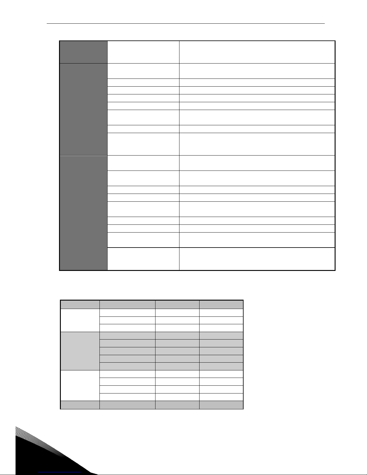
3.1.2
The standard features of NX inverters
INU
Sales code
NXI_AAAA 5/6
Standard features
FR4, FR6 and FR7
DC connection
IP21
Air cooling
Integrated charging
Alphanumeric control panel (in the
front of the module)
I/O modules A1 & A2
Standard board
Safety CE / UL
Sales code
NXI_AAAA 5/6
Standard features
FR8
DC connection
IP00
Air cooling
Integrated charging
Alphanumeric control panel (in the
front of the module)
I/O modules A1 & A2
Standard board
Safety CE / UL
Table 3-1. The standard features of NX inverters

12 • vacon receipt of delivery
Tel: +358-201-2121 • Fax: +358-201-212 205
3
3.2 Storage
If the inverter is to be stored before use, make sure that the ambient conditions are acceptable:
Storage temperature –40…+70C
Relative humidity <95%, no condensation
If the inverter is stored for over 12 months, contact Vacon service before connecting the inverter to
the power supply.
3.3 Maintenance
In normal conditions, Vacon NX inverters are maintenance-free. However, we recommend to clean
the heatsink with compressed air whenever necessary. The cooling fan can easily be changed if
necessary.
It may also be necessary to check the tightening torques of terminals at certain intervals.
3.4 Warranty
Only manufacturing defects are covered by the warranty. The manufacturer assumes no
responsibility for damages caused during or resulting from transport, receipt of the delivery,
installation, commissioning or use.
The manufacturer shall in no event and under no circumstances be held responsible for damages
and failures resulting from misuse, wrong installation, unacceptable ambient temperature, dust,
corrosive substances or operation outside the rated specifications.
Neither can the manufacturer be held responsible for consequential damages.
The Manufacturer's warranty period is 18 months from the delivery or 12 months from the
commissioning whichever expires first (General delivery terms NL92/Orgalime S92).
The local distributor may grant a warranty time different from the above. This warranty time shall be
specified in the distributor's sales and warranty terms. Vacon assumes no responsibility for any
other warranties than that granted by Vacon itself.
In all matters concerning the warranty, please contact your distributor first.
technical data vacon • 13
24-hour support: +358-(0)40-8371 150 • Email: vacon@vacon.com
4
4. TECHNICAL DATA
4.1 Introduction
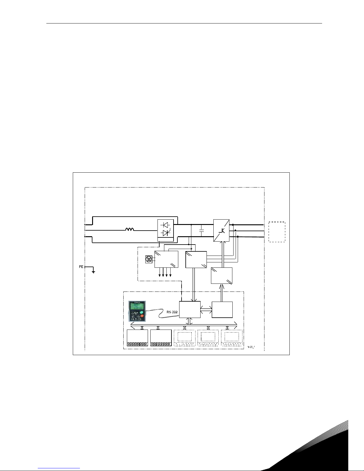
The figure below presents the block diagram of the Vacon NX inverter. The inverter mechanically
consists of two units, the Power Unit and the Control Unit.
The Power Unit contains an inverter bridge which consists of IGBT switches and produces a
symmetrical, 3-phase PWM-modulated AC voltage to the motor. To protect the DC-link capacitors,
the Power Unit also contains a charging circuit for controlled DC-link charge. Use the B+ and DCterminals in order to bypass the charging circuit.
The Motor and Application Control Block is based on microprocessor software. The microprocessor
controls the motor based on the information it receives through measurements, parameter settings,
control I/O and control keypad. The motor and application control block controls the motor control
ASIC which, in turn, calculates the IGBT positions. Gate drivers amplify these signals for driving the
IGBT inverter bridge.
Figure 4-1. The block diagram of Vacon NX inverter
=
B+
DC+
DC-
U
V
W
3~
Mains
Motor
Measurements
Gate
Drivers
Motor
Control
ASIC
Motor and
Application
Control
Control
Keypad
Fan
Current
Sensors
IGBT
Inverter
Output
EMCfilter
Power
Supply
Control
I/O
Control
I/O
Control
I/O
Control
I/O
Control
I/O
Integrated charging circuit
Control
module
Power
module
Charg.res.

14 • vacon technical data
Tel: +358-201-2121 • Fax: +358-201-212 205
4
The control keypad constitutes a link between the user and the inverter. The control keypad is used
for parameter setting, reading status data and giving control commands. It is detachable and can be
operated externally and is connected via a cable to the inverter. Instead of the control keypad, a PC
can be used to control the inverter if connected through a similar cable (VACON RS232PC –1.5M).
The basic control interface and the parameters (the Basic Application) are easy to use. If a more
versatile interface or parameters are required, a more suitable application can be chosen from the
"All in One+" Application Package. See the "All in One+" Application Manual for more information on
the different applications.
Optional I/O expander boards that increase the number of inputs and outputs to be used are also
available. For more information, contact the Manufacturer or your local distributor (see back cover).
technical data vacon • 15
24-hour support: +358-(0)40-8371 150 • Email: vacon@vacon.com
4
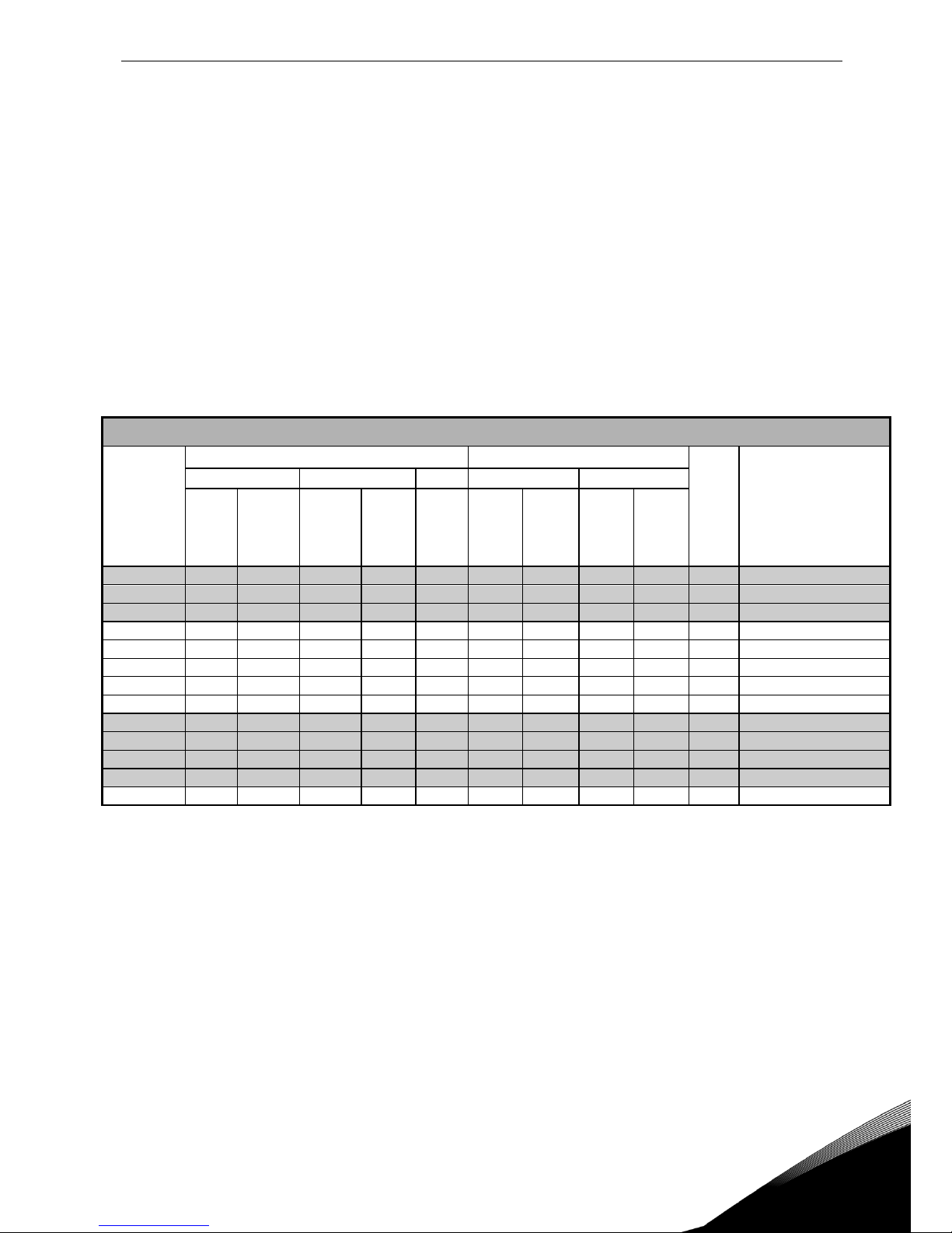
4.2 Power ratings
4.2.1
Vacon NXI_xxxx 5 – Supply voltage 465-800 Vdc, Motor voltage 380—500 Vac
High overload = Max current IS, 2 sec/20 sec, 150% overloadability, 1 min/10 min
Following continuous operation at rated output current, 150 % rated output
current (IH) for 1 min, followed by a period of load current less than rated
current, and of such duration that the r.m.s output current, over the duty cycle,
does not exceed rated output current (IH)
Low overload = Max current IS, 2 sec/20 sec, 110% overloadability, 1 min/10 min
Following continuous operation at rated output current, 110% rated output
current (IL) for 1 min, followed by a period of load current less than rated
current, and of such duration that the r.m.s output current, over the duty cycle,
does not exceed rated output current (IL)
Frames FR4…7 are available as IP21 and FR8 as IP 00
Table 4-1. Power ratings and dimensions of Vacon NX, supply voltage 465—800Vdc
Note: The rated currents in given ambient temperatures are achieved only when the switching
frequency is equal to or less than the factory default.
Motor voltage 380-500 Vac, 50/60 Hz, 3~
Inverter
type
Loadability
Motor shaft power
Frame
Dimensions and
weight
WxHxD/kg
Low
High
513Vdc supply
675Vdc supply
Rated
continuo
us
current
IL (A)
10%
overload
current
(A)
Rated
continuou
s current
IH (A)
50%
overload
current
(A)
Max
current
IS
10%
overload
40°C
P(kW)
50%
overload
50°C
P(kW)
10%
overload
40°C
P(kW)
50%
overload
50°C
P(kW)
NXI _0004 5
4.3
4.7
3.3 5 6.2
1.5
1.1
2.2
1.5
FR4
128x292x190/5
NXI _0009 5
9
9.9
7.6
11.4
14 4 3
5.5 4 FR4
128x292x190/5
NXI _0012 5
12
13.2
9
13.5
18
5.5 4 7.5
5.5
FR4
128x292x190/5
NXI _0016 5
16
17.6
12
18
24
7.5
5.5
11
7.5
FR6
195x519x237/16
NXI _0022 5
23
25.3
16
24
32
11
7.5
15
11
FR6
195x519x237/16
NXI _0031 5
31
34
23
35
46
15
11
18.5
15
FR6
195x519x237/16
NXI _0038 5
38
42
31
47
62
18.5
15
22
18.5
FR6
195x519x237/16
NXI _0045 5
46
51
38
57
76
22
18.5
30
22
FR6
195x519x237/16
NXI _0061 5
61 67
46
69
92
30
22
37
30
FR7
237x591x257/29
NXI _0072 5
72
79
61
92
122
37
30
45
37
FR7
237x591x257/29
NXI _0087 5
87
96
72
108
144
45
37
55
45
FR7
237x591x257/29
NXI _0105 5
105
116
87
131
174
55
45
75
55
FR7
237x591x257/29
NXI _0140 5
140
154
105
158
210
75
55
90
75
FR8
285x721x288/48
16 • vacon technical data
Tel: +358-201-2121 • Fax: +358-201-212 205
4
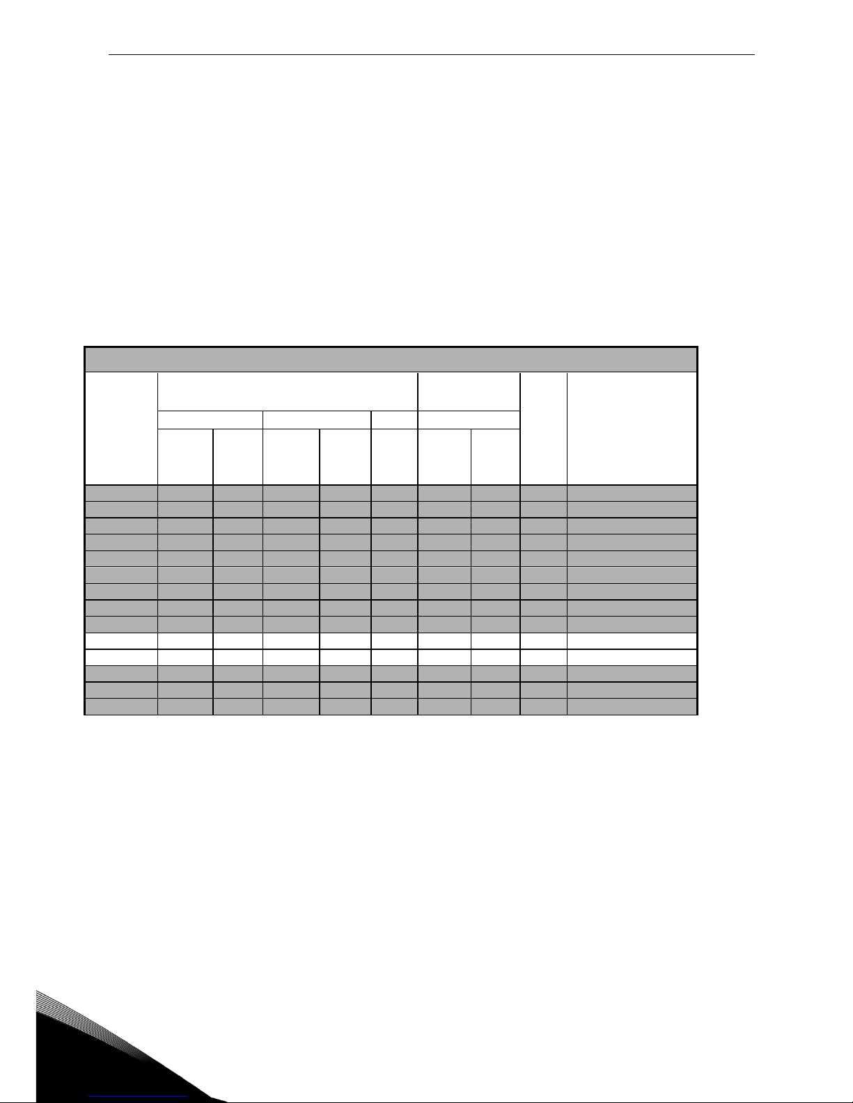
4.2.2
Vacon NXI_xxxx 6 – Supply voltage 640-1100 Vdc, Motor voltage 525—690 Vac
High overload = Max current IS, 2 sec/20 sec, 150% overloadability, 1 min/10 min
Following continuous operation at rated output current, 150 % rated output
current (IH) for 1 min, followed by a period of load current less than rated
current, and of such duration that the r.m.s output current, over the duty cycle,
does not exceed rated output current (IH)
Low overload = Max current IS, 2 sec/20 sec, 110% overloadability, 1 min/10 min
Following continuous operation at rated output current, 110% rated output
current (IL) for 1 min, followed by a period of load current less than rated
current, and of such duration that the r.m.s output current, over the duty cycle,
does not exceed rated output current (IL)
Frames FR4…7 are available as IP21 and FR8 as IP 00
Motor voltage 525-690 Vac, 50/60 Hz, 3~
Inverter
type
Loadability
Motor shaft
power
Frame
Dimensions and
weight
WxHxD/kg
Low
High
930Vdc supply
Rated
continuous
current IL
(A)
10%
overload
current
(A)
Rated
continuou
s current
IH (A)
50%
overload
current
(A)
Max
current
IS
10%
overload
40°C
P(kW)
50%
overload
50°C
P(kW)
NXI _0004 6
4.5 5 3.2 5 6.7 3 2.2
FR6
195x519x237/16
NXI _0005 6
5.5
6.1
4.5
6.8 9 4 3 FR6
195x519x237/16
NXI _0007 6
7.5
8.3
5.5
8.3
11
5.5 4 FR6
195x519x237/16
NXI _0010 6
10
11
7.5
11.3
15
7.5
5.5
FR6
195x519x237/16
NXI _0013 6
13.5
14.9
10
15
20
11
7.5
FR6
195x519x237/16
NXI _0018 6
18
19.8
13.5
20.3
27
15
11
FR6
195x519x237/16
NXI _0022 6
22
24.2
18
27
36
18.5
15
FR6
195x519x237/16
NXI _0027 6
27
29.7
22
33
44
22
18.5
FR6
195x519x237/16
NXI _0034 6
34
37
27
41
54
30
22
FR6
195x519x237/16
NXI _0041 6
41
45
34
51
68
37.5
30
FR7
237x591x257/29
NXI _0052 6
52
57
41
62
82
45
37,5
FR7
237x591x257/29
NXI _0062 6
62
68
52
78
104
55
45
FR8
285x721x288/48
NXI _0080 6
80
88
62
93
124
75
55
FR8
285x721x288/48
NXI _0100 6
100
110
80
120
160
90
75
FR8
285x721x288/48
Table 4-2. Power ratings and dimensions of Vacon NX, supply voltage 640—1100Vdc
Note: The rated currents in given ambient temperatures are achieved only when the switching
frequency is equal to or less than the factory default.
technical data vacon • 17
24-hour support: +358-(0)40-8371 150 • Email: vacon@vacon.com
4
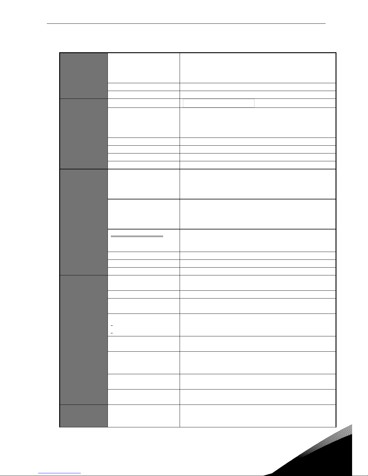
4.3 Technical information
DC connection
Input voltage Uin
465...800Vdc; 640...1100Vdc; –0%…+0% , the ripple voltage
of the inverter supply voltage generated during the
rectification of the fundamental frequency AC voltage must
be less than 50Vp-p.
Connection to DC supply
Once per minute or less (normal)
Starting delay
FR4–FR8: 2 s
Motor
connection
Output voltage
3 ~ 0 - Uin / 1.4
Continuous output
current
IH: Ambient temperature max. +50°C,
overload 1.5 x IH (1 min./10 min.)
IL: Ambient temperature max. +40°C,
overload 1.1 x IL (1 min./10 min.)
Starting torque
IS for two seconds, depends on the motor
Starting current
IS for 2 s every 20 s
Output frequency
0…320 Hz; 7200 Hz (special use)
Frequency resolution
Depends on application
Control
characteristics
Control method
Frequency control U/f
Open Loop Sensorless Vector Control
Closed Loop Frequency Control
Closed Loop Vector Control
Switching frequency
(see parameter 2.6.9)
NXI_xxxx 5: 1…16 kHz; Factory default 10 kHz
NXI_0072 and greater:
1…10 kHz; Factory default 3.6 kHz
NXI_xxxx 6: 1…6 kHz; Factory default 1.5 kHz
Frequency reference
Analogue input
Panel reference
Resolution 0.1% (10-bit), accuracy ±1%
Resolution 0.01 Hz
Field weakening point
30…320 Hz
Acceleration time
0…3000 sec
Deceleration time
0…3000 sec
Ambient
conditions
Ambient operating
temperature
–10°C (no frost)…+50°C: IH (FR10: max. +40ºC)
–10°C (no frost)…+40°C: IL
Storage temperature
–40°C…+70°C
Relative humidity
0 to 95% RH, non-condensing, non-corrosive,
no dripping water
Air quality:
chemical vapours
mechanical particles
IEC 721-3-3, unit in operation, class 3C2
IEC 721-3-3, unit in operation, class 3S2
Altitude
100% load capacity (no derating) up to 1,000 m
1-% derating for each 100m above 1000.; max. 3000m
Vibration
EN50178/EN60068-2-6
5…150 Hz
Displacement amplitude 0,25 mm (peak) at 5…15.8 Hz
Max acceleration amplitude 1 G at 15.8…150 Hz
Shock
EN50178, EN60068-2-27
UPS Drop Test (for applicable UPS weights)
Storage and shipping: max. 15 G, 11 ms (in package)
Enclosure class
FR4…7 IP21/NEMA1 standard
FR8 IP 00 standard
EMC
(at default
settings)
Immunity
Fulfils all EMC standards
18 • vacon technical data
Tel: +358-201-2121 • Fax: +358-201-212 205
4
Safety
EN 50178 (1997), EN 60204-1 (1996), EN 60950 (2000, 3rd
edition) (as relevant), CE, UL, CUL, FI, GOST R, IEC 61800-5;
(see unit nameplate for more detailed approvals)
Control
connections
Analogue input voltage
0…+10V, Ri = 200k, (–10V…+10V joystick control)
Resolution 0.1%, accuracy ±1%
Analogue input current
0(4)…20 mA, Ri = 250 differential
Digital inputs (6)
Positive or negative logic; 18…30VDC
Auxiliary voltage
+24V, ±15%, max. 250mA
Output reference voltage
+10V, +3%, max. load 10mA
Analogue output
0(4)…20mA; RL max. 500; Resolution 10bit;
Accuracy ±2%
Digital outputs
Open collector output, 50mA/48V
Relay outputs
2 programmable change-over relay outputs
Switching capacity 24VDC/8A, 250VAC/8A, 125VDC/0.4A
Min.switching load: 5V/10mA
Protections
Overvoltage trip limit
Undervoltage trip limit
NXI_5: 911VDC; NXI_6: 1200VDC
NXI_5: 333VDC; NXI_6: 460 VDC
Earth fault protection
In case of earth fault in motor or motor cable, only the
inverter is protected
Output phase supervision
Trips if any of the output phases is missing
Overcurrent protection
Yes
Unit overtemperature
protection
Yes
Motor overload protection
Yes
Motor stall protection
Yes
Motor underload
protection
Yes
Short-circuit protection of
+24V and +10V reference
voltages
Yes
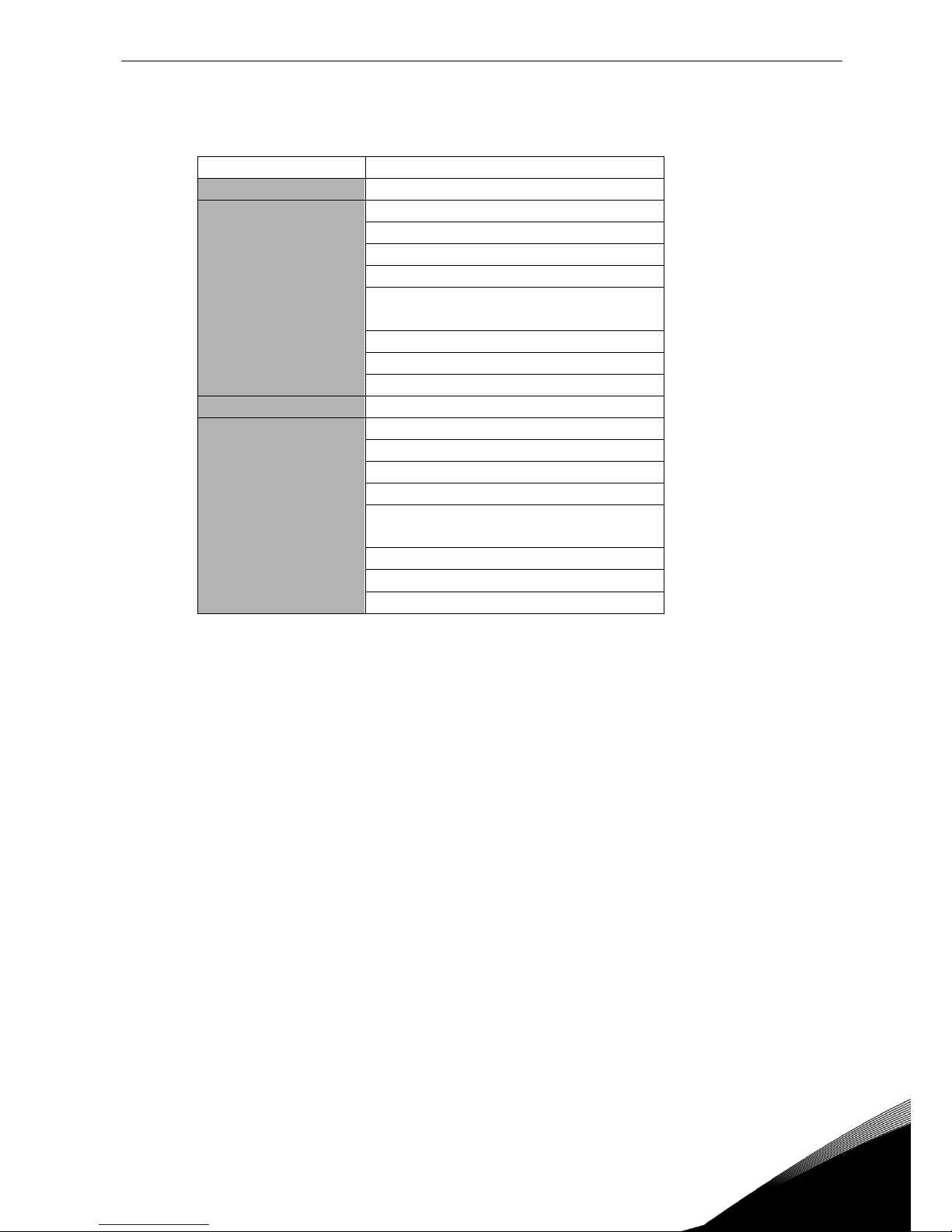
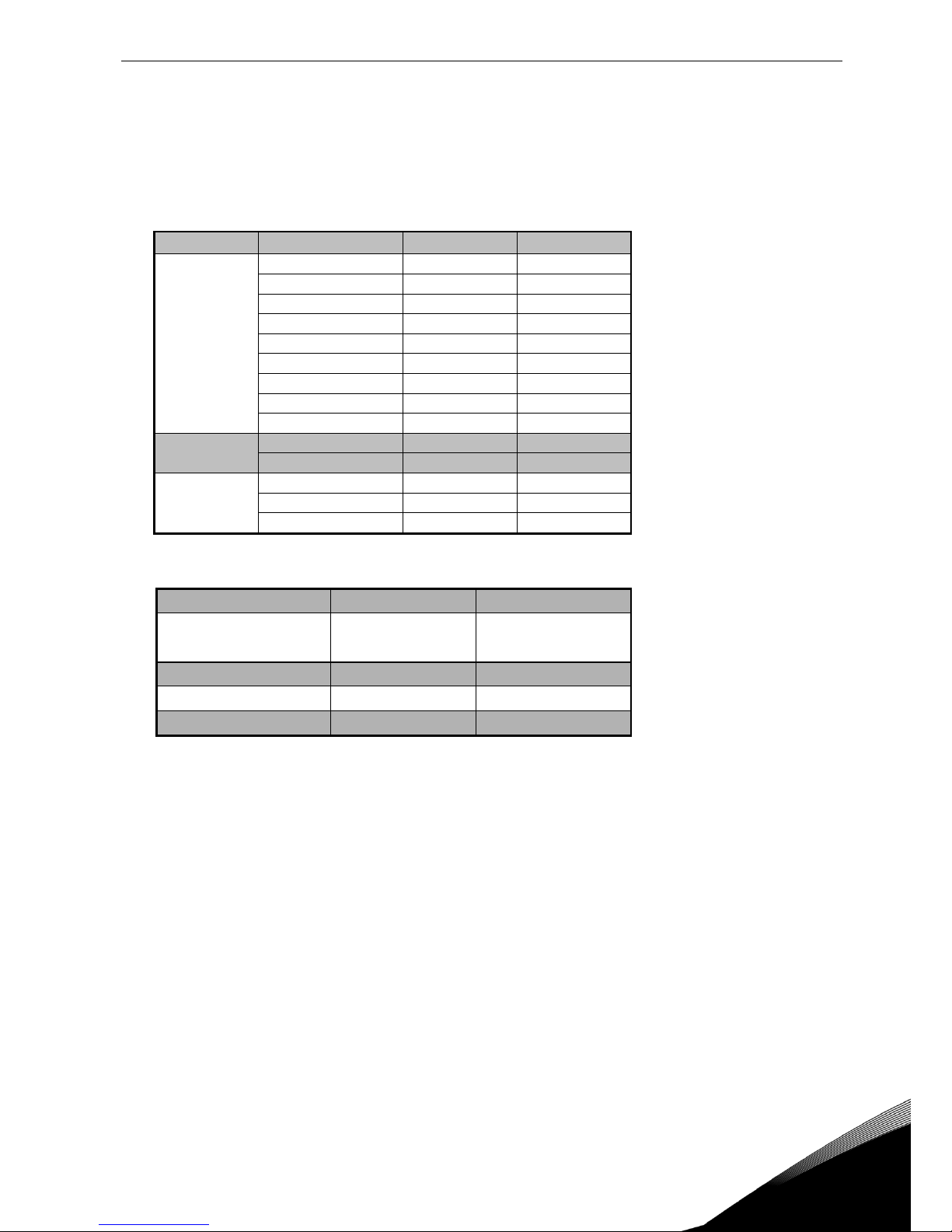
Table 4-3. Technical information
Structure
Inom (output)
Motor cos
Idc (input)
FR4
4.3
0.79
4.4 9 0.82
9.6
12
0.83
1.0
FR6
16
0.84
17.5
22
0.85
24.4
31
0.85
34.3
38
0.86
43
45
0.86
50
FR7
61
0.86
68
72
0.87
82
87
0.87
99
105
0.87
119
FR8
140
0.88
160
Table 4- 4 DC currents of Vacon NX, supply voltage 465 - 800Vdc
technical data vacon • 19
24-hour support: +358-(0)40-8371 150 • Email: vacon@vacon.com
4
Structure
Inom (output)
Motor cos
Idc (input)
FR6
4,5
0,81
4,7
5,5
0,82
5,9
7,5
0,83
8,1
10,0
0,84
10,9
13,5
0,85
14,9
18,0
0,85
19,9
22,
0,86
24,6
27,0
0,86
30,2
34,0
0,86
38,1
FR7
41,0
0,87
46
52,0
0,87
59
FR8
62,0
0,87
70
80,0
0,88
92
100,0
0,88
115
Table 4- 5. DC currents of Vacon NX, supply voltage 640 - 1100Vdc
Structure
NXI_xxxx 5 / F
NXI_xxxx 6 / F
FR4 0003-0007
FR4 0009-0012
165
235
FR6
1000
500
FR7
1650
900
FR8
3300
1800
Table 5- 1. DC-link capacitance by structure.

20 • vacon installation
Tel: +358-201-2121 • Fax: +358-201-212 205
5
5. INSTALLATION
5.1 Mounting
The inverter can be mounted in either a vertical or horizontal position on a wall or on the back plane
of a cubicle. Enough space must be reserved around the inverter to ensure sufficient cooling, see
Figure 5-6. You must follow the minimum dimensions for installation, see Table 5-6 and Table 5-7.
Also make sure that the mounting plane is relatively even.
The inverter is fixed with four screws (or bolts, depending on the unit size). The dimensions for
installation are presented in Figure 5-6 and Table 5-6.
Lift units bigger than FR7 out of the package using a jib crane. Ask the factory or your local
distributor for information on how to lift the unit safely.
The following pages show the dimensions for Vacon NX with a default enclosure in Figure 5-1, and
with flange mounting in Figures 5-2 and Figure 5-4. Dimensions for the opening needed in flange
mounting are given in Table 5-3 and Table 5-5.
installation vacon • 21
24-hour support: +358-(0)40-8371 150 • Email: vacon@vacon.com
5
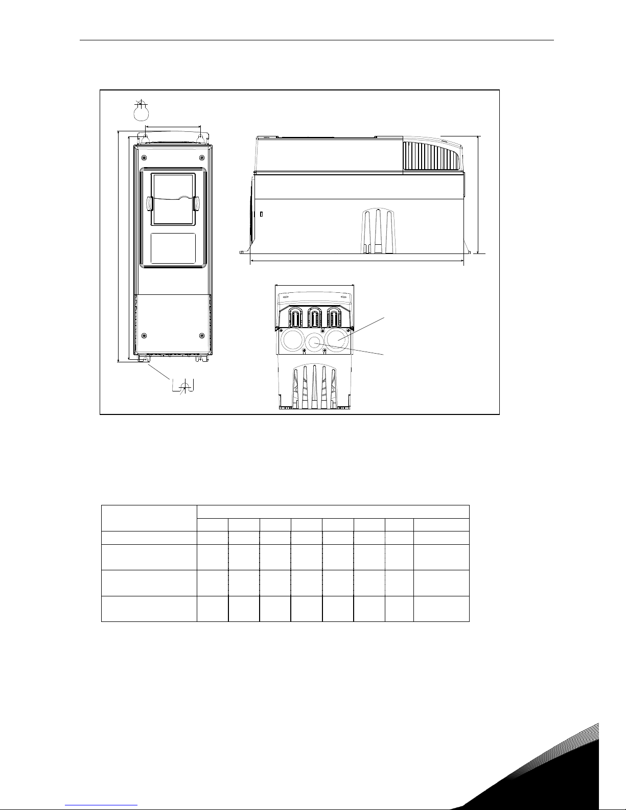
Figure 5-1. The dimensions of Vacon NX, IP21
Type
Dimensions [mm]
W1
W2
H1
H2
H3
D1 E1
NXI_0004—0012 5
128
100
327
313
292
190 7 3 x 28.3
NXI_0016—0045 5
NXI_0004—0034 6
195
148
558
541
519
237 9 3 x 37
NXI_0061—0105 5
NXI_0041—0052 6
237
190
630
614
591
257 9 3 x 47
NXI_0140 5
NXI_0062—0100 6
285
255
755
732
721
312 9 3 x 59
Table 5-1. Dimensions for different inverter types, IP21
W1
W2
H1 H2
Ø
D1
H3
fr5ip21.fh8
Ø
E1Ø
E2Ø*
22 • vacon installation
Tel: +358-201-2121 • Fax: +358-201-212 205
5
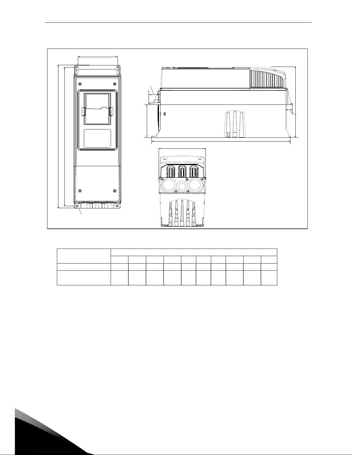
Figure 5-2. Vacon NX dimensions, IP21 with flange, FR4 and FR6
Type
Dimensions [mm]
W1
W2
H1
H2
H3
H4
H5
D1
D2 NXI_0004—0012 5
128
113
337
325
327
30
22
190
77
7
NXI_0016—0045 5
NXI_0004—0034 6
195
170
560
549
558
30
20
237
106
6.5
Table 5-2. Dimensions for inverter types FR4 and FR6, IP21 with flange
W2
H1 H2
W1
D1
D2
H4
H5
fr5ip21kaulus.fh8
Ø
H3

installation vacon • 23
24-hour support: +358-(0)40-8371 150 • Email: vacon@vacon.com
5
Figure 5-3. The opening needed for flange mounting, FR4 and FR6
Type
Dimensions [mm]
W1
W2
W3
H1
H2
H3
H4
NXI_0004—0012 5
123
113 – 315
325 – 5
6.5
NXI_0016—0045 5
NXI_0004—0034 6
185
170
157
539
549 7 5
6.5
Table 5-3. Dimensions for the opening for flange mounting, FR4 and FR6
fr6aukko.fh8
W2
H2
H1
W1W3
H3
Ø
H4

24 • vacon installation
Tel: +358-201-2121 • Fax: +358-201-212 205
5
Figure 5-4. Vacon NX dimensions, IP21 with flange, FR4 and FR6
Type
Dimensions [mm]
W1
W2
W3
W4
H1
H2
H3
H4
H5
H6
H7
D1
D2
NXI_0061—0105 5
NXI_0041—0052 6
237
175
270
253
652
632
630
188.5
188.5
23
20
257
117
5.5
NXI_0140 5
NXI_0062—0100 6
285 – 355
330
755
–
745
258
265
43
57
288
110
9
Table 5-4. Dimensions for inverter types FR7 and FR8, IP21 with flange
W3
W1
W2
H1 H2
H3
D1
D2
H4
H4
H5
H7
W4
H6
fr7kaulusip21.fh8
installation vacon • 25
24-hour support: +358-(0)40-8371 150 • Email: vacon@vacon.com
5
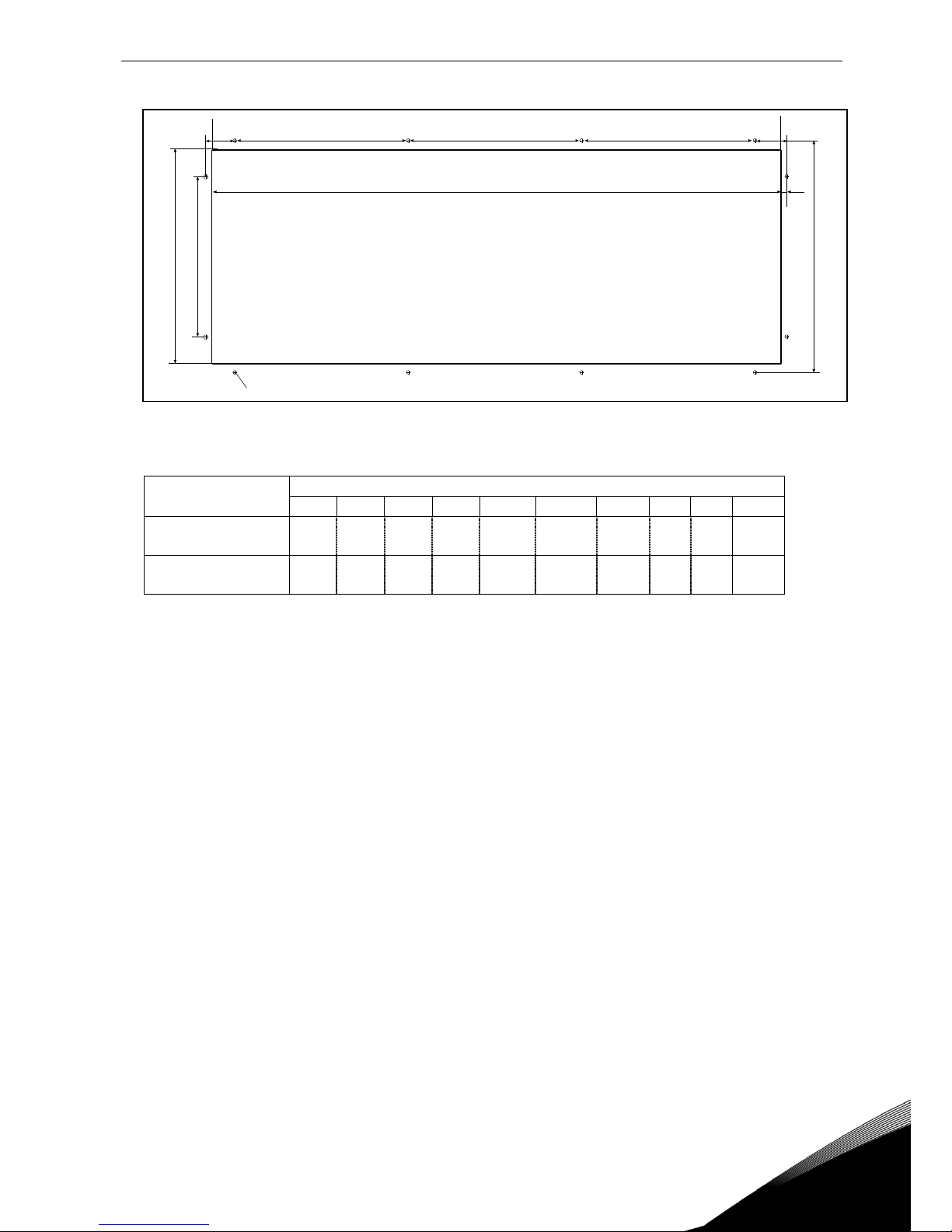
Figure 5-5. The opening needed for flange mounting, FR7/FR8
Type
Dimensions [mm]
W1
W2
W3
H1
H2
H3
H4
H5
H6
NXI_50061—0105
NXI_0041—0052 6
233
175
253
619
188.5
188.5
34.5
32 7 5.5
NXI_0140 5
NXI_0062—0100 6
301 – 330
810
258
265 – – – 9
Table 5-5. Dimensions for the opening for flange mounting, FR7/FR8
W1 W2
H1
H2 H2
H3
H4
H5
H6
Ø
W3
fr7aukko.fh8
 Loading...