

Vacon NXI FI9 series, NXI FI13 series, NXI FI14 series, NXI FI10 series, NXI FI12 series User Manual

vacon® nxi
inverters
fi9-fi14
user manual
AT LEAST THE 10 FOLLOWING STEPS OF THE
START-UP QUICK GUIDE
MUST BE PERFORMED
DURING THE INSTALLATION AND COMMISSIONING.
IF ANY PROBLEMS OCCUR, PLEASE CONTACT YOUR LOCAL DISTRIBUTOR.
Start-up Quick Guide
1. Check that the delivery corresponds to your order, see Chapter 3.
2. Before taking any commissioning actions, read carefully the safety instructions
in Chapter 1.
3. Before the mechanical installation, check the minimum clearances around the
unit and check the ambient conditions in Chapter 5.
4. Check the size of the motor cable, DC supply cable, and mains fuses, and check
the cable connections. Read Chapters 6.1.1.1 6.1.1.6.
5. Follow the installation instructions, see Chapter 6.1.1.8.
6. The sizes and grounding of control connections are explained in Chapter 6.2.2.
7. If the Start-Up wizard is active, select the language you want the keypad and the
application to use and confirm by pressing the enter button. If the Start-Up
wizard is not active, follow the instructions in 7a and 7b below.
8. 7a. Select the language of the keypad from Menu M6, page 6.1. Instructions on
using the keypad are given in Chapter 7.
9. 7b. Select the application you want to use from Menu M6, page 6.2. Instructions
on using the keypad are given in Chapter 7.
10. All parameters have factory default values. To ensure proper operation, check
the rating plate data for the values below and the corresponding parameters of
parameter group G2.1.
• nominal voltage of the motor
• nominal frequency of the motor
• nominal speed of the motor
• nominal current of the motor
• motor cos
All parameters are explained in the All in One Application Manual.
11. Follow the commissioning instructions, see Chapter 8.
12. The VACON
®
NX Inverter is now ready for use.
Vacon Ltd is not responsible for the use of the inverters against the
instructions.

CONTENTS
VACON®
INDEX
1 SAFETY
2 EU DIRECTIVE
3 RECEIPT OF DELIVERY
4 TECHNICAL DATA
5 INSTALLATION
6 CABLING AND CONNECTIONS
7 CONTROL KEYPAD
8 COMMISSIONING
9 FAULT TRACING

4 vacon
Local contacts: https://www.danfoss.com/en/contact-us/contacts-list/
1
ABOUT THE VACON® NXI USER'S MANUAL
Congratulations for choosing VACON® NX Inverters!
The User's Manual will provide you with the necessary information about the installation,
commissioning and operation of VACON® NX Inverters. We recommend that you carefully study
these instructions before powering up the inverter for the first time.
In the All in One Application Manual you will find information about the different applications
included in the All in One Application Package. Should these applications not meet the requirements
of your process, please contact the manufacturer for information on special applications.
This manual is available in both paper and electronic editions. We recommend you to use the
electronic version if possible. If you have the electronic version at your disposal, you will be able to
benefit from the following features:
The manual contains several links and cross-references to other locations in the manual, which
makes it easier to move around in the manual. The reader can thus easily find and check things.
The manual also contains hyperlinks to web pages. To visit these web pages through the links, you
must have an internet browser installed on your computer.

vacon 5
Local contacts: https://www.danfoss.com/en/contact-us/contacts-list/
VACON® NXI User's Manual
Index
Document code: DPD00909D
Date: 30/01/2019
1. SAFETY .......................................................................................................................... 8
1.1 Warnings ...................................................................................................................................... 8
1.2 Safety instructions ....................................................................................................................... 8
1.3 Grounding and earth fault protection ........................................................................................ 9
1.4 Running the motor ...................................................................................................................... 9
2. EU DIRECTIVE .............................................................................................................. 10
2.1 CE marking ................................................................................................................................ 10
2.2 EMC directive ............................................................................................................................. 10
2.2.1 Introduction ....................................................................................................................... 10
2.2.2 Technical criteria .............................................................................................................. 10
2.2.3 VACON® inverter EMC classification ............................................................................... 10
2.2.4 Manufacturer's declaration of conformity ...................................................................... 10
3. RECEIPT OF DELIVERY ................................................................................................. 12
3.1 Type designation code. .............................................................................................................. 12
3.1.1 FI9 FI14 ........................................................................................................................... 12
3.2 Storage ....................................................................................................................................... 13
3.2.1 Capacitor reforming .......................................................................................................... 13
3.3 Maintenance .............................................................................................................................. 13
3.4 Disposal ...................................................................................................................................... 14
4. TECHNICAL DATA......................................................................................................... 15
4.1 Introduction................................................................................................................................ 15
4.2 NX Inverter drive Power ratings ............................................................................................... 17
4.2.1 Supply voltage 465-800 Vdc, Motor voltage 380 500 Vac ............................................. 17
4.2.2 Supply voltage 640-1100 Vdc, Motor voltage 525 690 Vac ........................................... 18
4.2.3 Overload capability ............................................................................................................ 18
4.3 Technical information ............................................................................................................... 20
4.4 Derating...................................................................................................................................... 23
4.4.1 Ambient temperature ....................................................................................................... 24
4.4.2 High altitude installation .................................................................................................. 24
5. INSTALLATION ............................................................................................................. 26
5.1 Mounting .................................................................................................................................... 26
5.2 Fan cooling ................................................................................................................................. 33
5.2.1 Enclosure sizes FI9 to FI14............................................................................................... 33
5.2.2 Arranging ventilation of the enclosure ............................................................................ 34
6. CABLING AND CONNECTIONS ...................................................................................... 37
6.1 Power unit .................................................................................................................................. 37
6.1.1 Power connections ............................................................................................................ 45
6.1.1.1 DC supply and motor cables .................................................................................... 45
6.1.1.2 Control cable ............................................................................................................. 45
6.1.1.3 Fuses, NXI_xxxx 5 ..................................................................................................... 45

6 vacon
Local contacts: https://www.danfoss.com/en/contact-us/contacts-list/
1
6.1.1.4 Fuses, NXI_xxxx 6 ..................................................................................................... 46
6.1.1.5 Inverter supply and motor cables , NXI_xxxx 5....................................................... 47
6.1.1.6 Terminal sizes, NXI_xxxx 5 ...................................................................................... 48
6.1.1.7 Inverter supply and motor cables, NXI_xxxx 6 ....................................................... 49
6.1.1.8 Terminal sizes, NXI_xxxx 6 ...................................................................................... 50
6.1.2 Installation instructions .................................................................................................... 51
6.1.2.1 VACON® NXI enclosures .......................................................................................... 53
6.1.3 Cable installation and the UL standards ......................................................................... 55
6.1.4 Cable and motor insulation checks ................................................................................. 55
6.2 Control unit ................................................................................................................................ 56
6.2.1 Control voltage (+24V/EXT +24V) ...................................................................................... 56
6.2.2 Control connections .......................................................................................................... 57
6.2.2.1 Control cables ........................................................................................................... 59
6.2.2.2 Galvanic isolation barriers ....................................................................................... 59
6.2.3 Control terminal signals ................................................................................................... 60
6.2.3.1 Digital input signal inversions ................................................................................. 61
6.2.3.2 Jumper selections on the OPT-A1 basic board ...................................................... 62
7. CONTROL KEYPAD ....................................................................................................... 64
7.1 Indicators on the keypad display .............................................................................................. 64
7.1.1 Drive status indications .................................................................................................... 64
7.1.2 Control place indications .................................................................................................. 65
7.1.3 Status LEDs (green green red) .................................................................................. 65
7.1.4 Text lines............................................................................................................................ 66
7.2 Keypad push-buttons ................................................................................................................ 67
7.2.1 Button descriptions ........................................................................................................... 67
7.3 Navigation on the control keypad ............................................................................................. 68
7.3.1 Monitoring menu (M1)....................................................................................................... 70
7.3.2 Parameter menu (M2) ....................................................................................................... 71
7.3.3 Keypad control menu (M3)................................................................................................ 73
7.3.3.1 Selection of control place......................................................................................... 73
7.3.3.2 Keypad reference ...................................................................................................... 73
7.3.3.3 Keypad direction ....................................................................................................... 73
7.3.3.4 Stop button activated ................................................................................................ 74
7.3.4 Active faults menu (M4) .................................................................................................... 75
7.3.4.1 Fault types ................................................................................................................. 75
7.3.4.2 Fault codes ................................................................................................................ 77
7.3.4.3 Fault time data record .............................................................................................. 83
7.3.5 Fault history menu (M5).................................................................................................... 84
7.3.6 System menu (M6) ............................................................................................................ 85
7.3.6.1 Selection of language ............................................................................................... 88
7.3.6.2 Application selection ................................................................................................ 88
7.3.6.3 Copy parameters ...................................................................................................... 89
7.3.6.4 Parameter comparison ............................................................................................ 91
7.3.6.5 Safety ......................................................................................................................... 92
7.3.6.6 Keypad settings ......................................................................................................... 94
7.3.6.7 Hardware settings .................................................................................................... 96
7.3.6.8 System info ................................................................................................................ 98
7.3.7 Expander board menu (M7) ............................................................................................ 102
7.4 Further keypad functions ........................................................................................................ 103
8. COMMISSIONING .........................................................................................................104

vacon 7
Local contacts: https://www.danfoss.com/en/contact-us/contacts-list/
8.1 Safety ........................................................................................................................................ 104
8.2 Commissioning the inverter ................................................................................................... 104
9. FAULT TRACING ..........................................................................................................107
8 vacon SAFETY
Local contacts: https://www.danfoss.com/en/contact-us/contacts-list/
1
1. SAFETY
1.1 Warnings
1
The components of the power unit of the inverter are live when the
VACON® NX is connected to DC supply. Coming into contact with this
voltage is extremely dangerous and may cause death or severe
injury. The control unit is isolated from mains potential.
2
The DC supply and motor terminals are live when the VACON® NX is
connected to DC supply, even if the motor is not running.
3
The control I/O-terminals are isolated from the mains potential.
However, the relay outputs and other I/O-terminals may have dangerous
control voltage present even when the VACON® NX is disconnected from
the DC supply.
4
The inverter has a large capacitive leakage current.
5
If the inverter is used as a part of a machine, the machine manufacturer
is responsible for providing the machine with a main switch (EN 60204-1).
6
Only spare parts delivered by manufacturer can be used.
1.2 Safety instructions
1
The VACON® NX inverter is meant for fixed installations only.
2
Do not perform any measurements when the inverter is connected to the
DC supply.
3
After having disconnected the inverter from the DC supply, wait until the
fan stops and the indicators on the keypad go out (if no keypad is
attached see the indicator through the keypad base). Wait 5 more
minutes before doing any work on VACON® NX connections. Do not even
open the cover before this time has expired.
4
Do not perform any voltage withstand tests on any part of VACON® NX.
There is a certain procedure according to which the tests shall be performed. Ignoring this procedure may result in damaged product.
5
Prior to measurements on the motor or the motor cable, disconnect the
motor cable from the inverter.
6
Do not touch the components on the circuit boards. Static voltage discharge may damage the components.
7
Before connecting the inverter to DC supply, make sure that the VACON®
NX front and cable covers are closed.
ONLY A COMPETENT ELECTRICIAN MAY CARRY OUT
THE ELECTRICAL INSTALLATION
WARNING
SAFETY vacon 9
Local contacts: https://www.danfoss.com/en/contact-us/contacts-list/
1
1.3 Grounding and earth fault protection
The VACON® NX inverter must always be earthed with an grounding conductor connected to the
grounding terminal.
The earth fault protection inside the inverter only protects the inverter against earth faults in the
motor or the motor cable.
Due to the high capacity currents present in the inverter, fault current protective switches may not
function properly. If fault current protective switches are used, they need to be tested with earth
fault currents present during possible fault situations.
1.4 Running the motor
Warning symbols
For your own safety, please pay special attention to the instructions marked with the following
symbols:
=
Dangerous voltage
WARNING
=
General warning
HOT SURFACE
=
Hot surface Risk of burn
MOTOR RUN CHECK LIST
1
Before starting the motor, check that the motor is mounted properly and
ensure that the machine connected to the motor allows the motor to be
started.
2
Set the maximum motor speed (frequency) according to the motor and
the machine connected to it.
3
Before reversing the motor, make sure that this can be done safely.
4
Make sure that no power correction capacitors are connected to the
motor cable.
5
Make sure that the motor terminals are not connected to mains
potential.
NOTE! You can download the English and French product manuals with applicable safety, warning
and caution information from https://www.danfoss.com/en/service-and-support/.
REMARQUE Vous pouvez télécharger les versions anglaise et française des manuels produit
sur le site https://www.danfoss.com/en/service-and-support/.
WARNING

10 vacon receipt of delivery
Local contacts: https://www.danfoss.com/en/contact-us/contacts-list/
2
2. EU DIRECTIVE
2.1 CE marking
The CE marking on the product guarantees the free movement of the product within the EEA
(European Economic Area). It also guarantees that the product complies with applicable directives
(for example, the EMC Directive and other possible so-called new method directives). VACON® NX
Inverters carries the CE label as a proof of compliance with the Low Voltage Directive (LVD), Electro
Magnetic Compatibility (EMC) Directive and RoHS Directive.
2.2 EMC directive
2.2.1
Introduction
The EMC Directive provides that the electrical apparatus must not excessively disturb the
environment it is used in, and, on the other hand, it shall have an adequate level of immunity toward
other disturbances from the same environment.
The compliance of VACON® NX Inverters with the EMC Directive is verified with Technical
Construction Files (TCF) and checked and approved by SGS FIMKO, which is a Notified Body. The
Technical Construction Files are used to authenticate the conformity of VACON® NX Inverters with
the Directive because it is impossible to test such a large product family in a laboratory environment
and because the combinations of installation vary greatly.
2.2.2
Technical criteria
Our basic idea was to develop a range of inverters offering the best possible usability and costefficiency. EMC compliance was a major consideration from the outset of the design.
2.2.3
VACON® inverter EMC classification
Factory delivered VACON® NX inverters are Class T equipment, which fulfil all EMC immunity
requirements (standard EN 61800-3) .
Class T:
Class T equipment have a small earth leakage current and can be used with floating DC input.
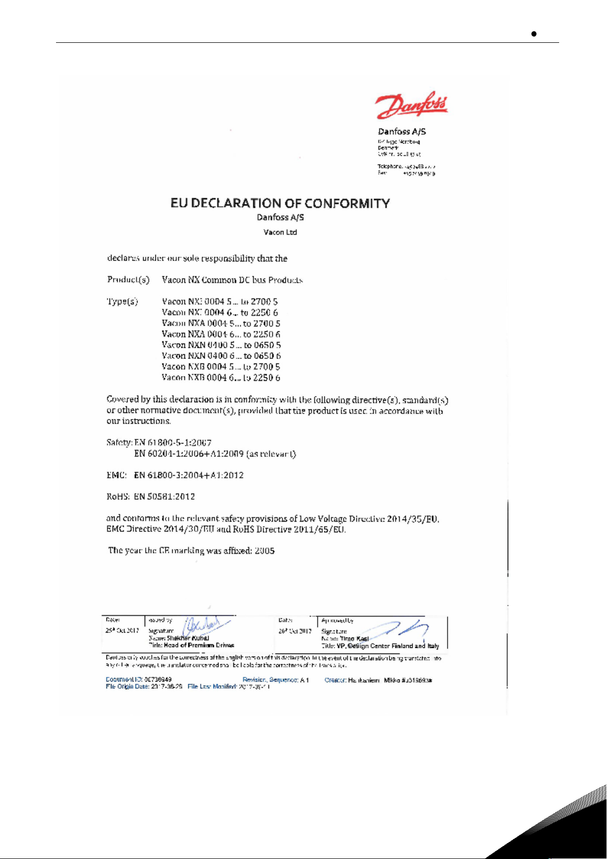
2.2.4
Manufacturer's declaration of conformity
The following page presents the photocopy of the Manufacturer's Declaration of Conformity assuring
the compliance of VACON® Inverters with the EMC-directives
Warning: This product is of the restricted sales distribution class according to IEC 61800-3. In
residential areas, this product may cause radio interference in which case the user may be required
to take adequate measures.
receipt of delivery vacon 11
Local contacts: https://www.danfoss.com/en/contact-us/contacts-list/
2
12 vacon receipt of delivery
Local contacts: https://www.danfoss.com/en/contact-us/contacts-list/
3
3. RECEIPT OF DELIVERY
VACON® NX inverters have undergone scrupulous tests and quality checks at the factory before they
are delivered to the customer. However, after unpacking the product, check that no signs of
transportation damage is to be found on the product and that the delivery is complete (compare the
type designation of the product to the code below, see the figure below.
Should the drive have been damaged during the shipping, please contact primarily the cargo
insurance company or the carrier.
If the delivery does not correspond to your order, contact the supplier immediately.
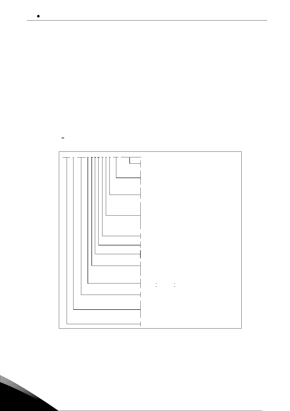
3.1 Type designation code.
3.1.1
FI9 FI14
Figure 3-1. VACON® NX type designation code, FI9 - FI14
NX
AAAA
T 0 C S S A1A2000000
V
2A
I
Nominal current (low overload)
0004 = 4A, 0520 = 520A, etc.
Nominal supply voltage (3-phase):
5 = 380 500Vac / 465 800Vdc
6 = 525 690Vac / 640 1100Vdc
Control keypad:
A = standard (alpha-numeric)
B = no local control keypad
F = dummy keypad
G = graphic display
Enclosure class:
2 = IP21, FR4...7
0 = IP00, FR8, FI9...14
EMC emission level:
T = fulfils standard EN61800-3 for IT networks
0 = N/A (no brake chopper)
Hardware modifications; Module type - S - Boards
S = Direct connection, standard boards, FR4...8
V = Direct connection, varnished boards, FR4...8
F= Fiber connection, standard boards
G = Fiber connection, varnished boards
Option boards; each slot is represented by two characters where:
A = basic I/O board, B = expander I/O board,
C = fieldbus board, D = special board
S = Standard air cooled drive
A =Standard air cooled power unit - transformer supply for main fan
U = Standard air cooled power unit - external supply for main fan
C = INU - with integrated charging circuit
I = INU - no charging circuit
N = Standard 6-pulse - no chokes
S = Standard 6-pulse connection with chokes
2 = AFE module
5 = AFE module + LCL filter
3 = FFE module
6 = FFE module + AC choke
8 = BCU Brake chopper unit
Module type:
A = AFE Active Front End
B = BCU Brake Chopper Unit
F = FFE Fundamental Front End
I = INU Inverter
N = Non regenerative Front End
Product generation

receipt of delivery vacon 13
Local contacts: https://www.danfoss.com/en/contact-us/contacts-list/
3
3.2 Storage
If VACON® NX Inverter is to be stored before use, make sure that the ambient conditions are
acceptable:
Storage temperature: -40...+158°F)
Relative humidity: 0 to 95%, no condensation
If you must keep the VACON® NX Active Front End in storage for a long time, you must connect the
power to the VACON® NX Active Front End each year. Keep the power on for a minimum of 2 hours.
We do not recommend a long storage time. If the storage time is more than 12 months, you must
charge the electrolytic DC capacitors with caution. To reform the capacitors, obey the instructions in
Chapter 3.2.1 Capacitor reforming.
3.2.1
Capacitor reforming
After a long storage time, it is necessary to reform the capacitors to prevent damage to the
capacitors. To make sure that the possible high leakage current through the capacitors stays in
minimum, use a DC-power supply with an adjustable current limit.
1. Set the current limit to 300-800mA to agree with the size of the drive.
2. Connect the DC-power supply to the B+/Bterminals (DC+ to B+, DC- to B-) of the DC-link or
directly to the capacitor terminals.
3. Set the DC-voltage to the nominal DC-voltage level of the Active Front End (1.35*Un AC) and
keep the power on for 1 hour, at minimum. If the Active Front End was in store for much longer
than 12 months and the capacitors were not charged, speak to the factory to get instructions
before you connect the power.
3.3 Maintenance
All technical devices, drives as well, need a certain amount of care-taking and failure preventive
maintenance. To maintain trouble-free operation of the drive, environmental conditions, as well as
load, line power, process control, etc. have to be within specifications, determined by manufacturer.
If all conditions are in accordance with the manufacturer's specifications, there are no other
concerns, but to provide a cooling capacity high enough for the power- and control circuits. This
requirement can be met by making sure, that the cooling system works properly. Operation of
cooling fans and cleanness of the heat sink should be verified regularly.
Regular maintenance is recommended to ensure trouble free operation and long lifetime of the
drive. At least the issues listed in the following table should be included in the regular maintenance.
14 vacon receipt of delivery
Local contacts: https://www.danfoss.com/en/contact-us/contacts-list/
3
TABLE 5. Maintenance interval
Interval
Maintenance
12 months (if unit stored)
Capacitor reforming, see Chapter
3.2.1
6 - 24 months (The interval is
different in different
environment.)
Check tightening torque of the
input and output terminals and
I/O terminals.
Clean the heat sink.
Clean the cooling tunnel.
Check operation of the cooling
fan, check for corrosion on
terminals, bus bars and other
surfaces.
Check the door filters.
5 - 7 years
Change the cooling fans.
• Main fan of the unit.
• Fan of the LCL filter.
• Internal IP54 (UL Type 12)
fan.
• Cabinet cooling fan/filter.
5 - 10 years
Change the DC bus capacitors if
DC voltage ripple is high.
It is also recommended to record all actions and counter values with dates and time for follow up of
maintenance.
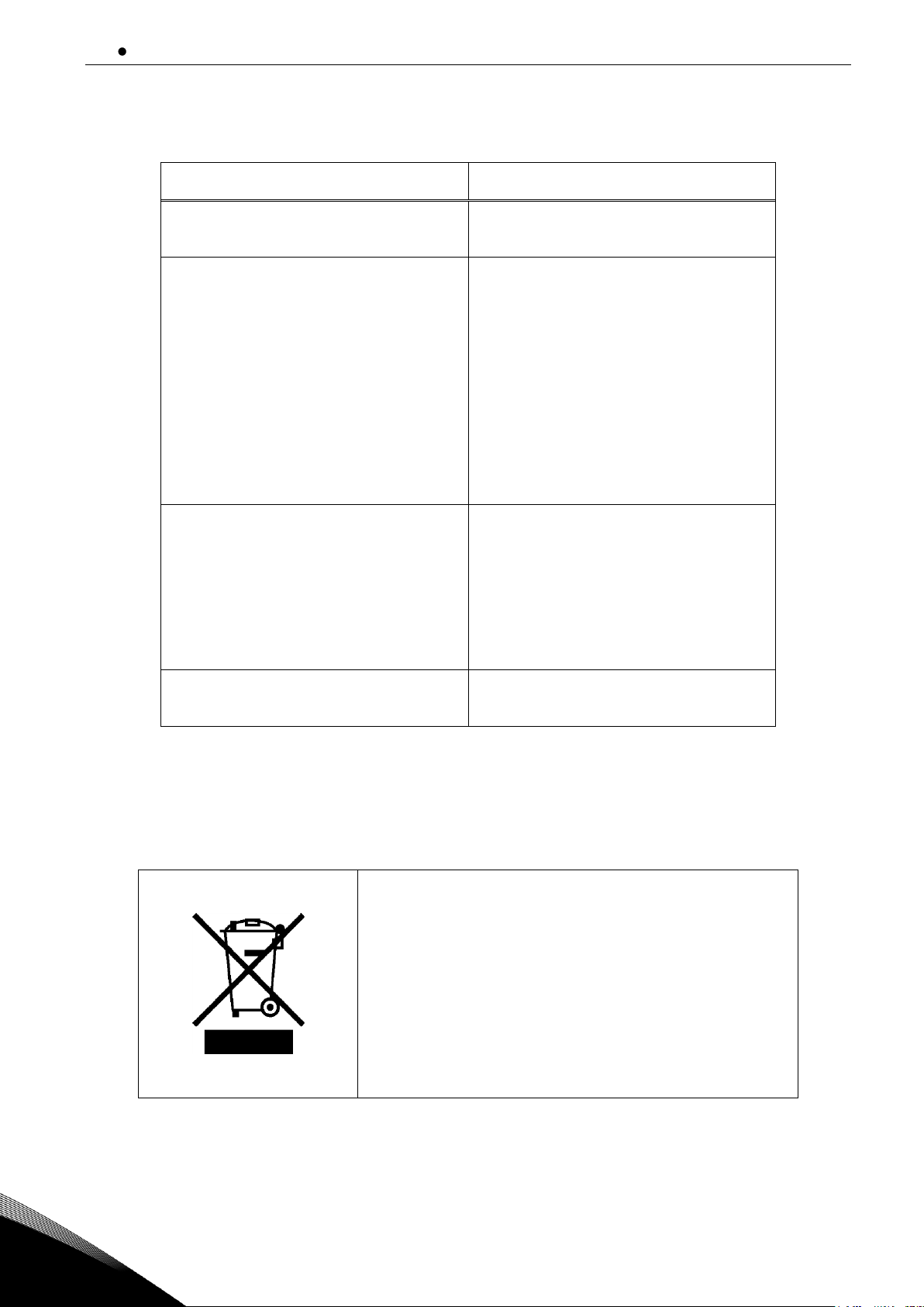
3.4 Disposal
When the drive is at the end of its operation life, do not
discard it as a part of municipal waste. You can recycle
the primary components of the drive. You must
disassemble some components before you can remove
the different materials. Recycle the electrical and
electronic components as waste.
To make sure that the waste is recycled correctly, send
the waste to a recycling centre. You can also send the
waste back to the manufacturer. Obey the local and
other applicable regulations.
technical data vacon 15
Local contacts: https://www.danfoss.com/en/contact-us/contacts-list/
4
4. TECHNICAL DATA
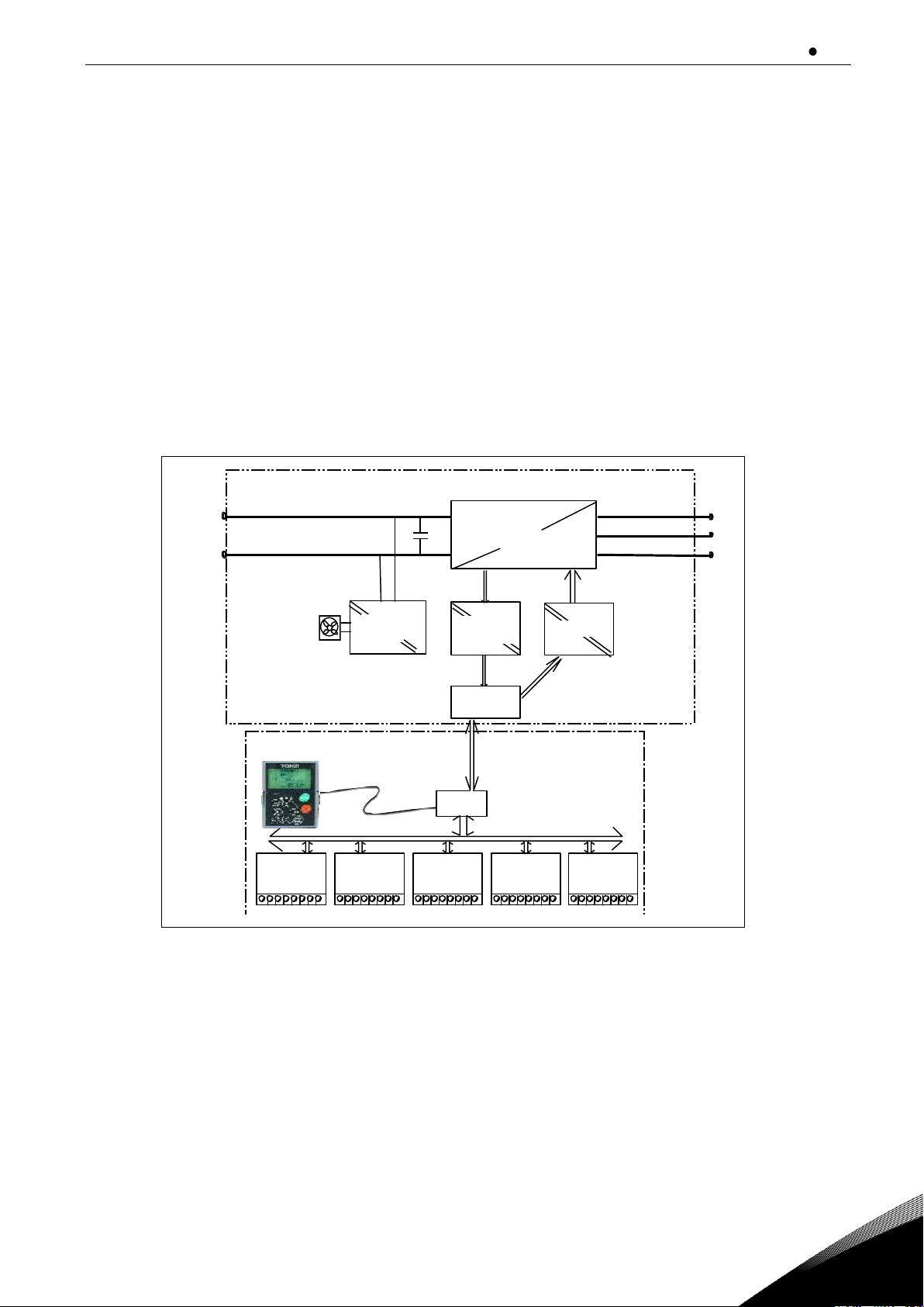
4.1 Introduction
The figure below presents the block diagram of the VACON® NX inverter. The inverter mechanically
consists of two units, the Power Unit and the Control Unit.
The Power Unit contains an inverter bridge which consists of IGBT switches and produces a
symmetrical, 3-phase PWM-modulated AC voltage to the motor.
The Motor and Application Control Block is based on microprocessor software. The microprocessor
controls the motor based on the information it receives through measurements, parameter settings,
control I/O and control keypad. The motor and application control block controls the motor control
ASIC which, in turn, calculates the IGBT positions. Gate drivers amplify these signals for driving the
IGBT inverter bridge.
Figure 4-1. The block diagram of VACON® NXI inverter
U
V
W
RS 232
NK4_1
B+
B-
Measurements
Driver
ASIC
Control
Control
Keypad
Fan
IGBT
bridge
Power
Supply
I/O
Slot A
I/O
Slot B
Control
module
Power
module
I/O
Slot C
I/O
Slot D
I/O
Slot E

16 vacon technical data
Local contacts: https://www.danfoss.com/en/contact-us/contacts-list/
4
The control keypad constitutes a link between the user and the inverter. The control keypad is used
for parameter setting, reading status data and giving control commands. It is detachable and can be
operated externally and is connected via a cable to the inverter. Instead of the control keypad, a PC
can be used to control the inverter if connected through a similar cable (VACON RS232PC 1.5M).
The basic control interface and the parameters (the Basic Application) are easy to use. If a more
versatile interface or parameters are required, a more suitable application can be chosen from the
"All in One+" Application Package. See the "All in One+" Application Manual for more information on
the different applications.
Optional I/O expander boards that increase the number of inputs and outputs to be used are also
available. For more information, contact the Manufacturer or your local distributor (see back cover).
technical data vacon 17
Local contacts: https://www.danfoss.com/en/contact-us/contacts-list/
4
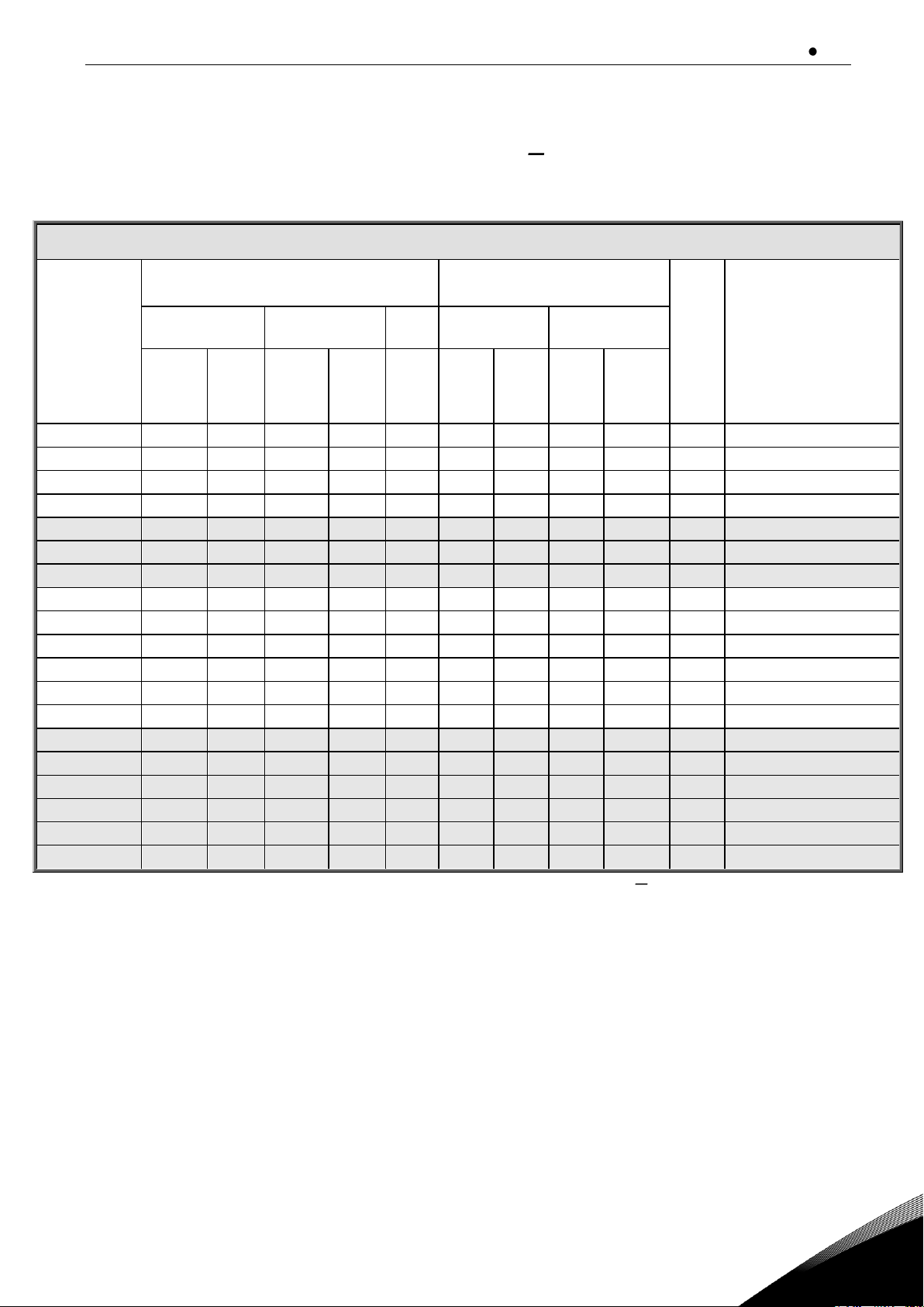
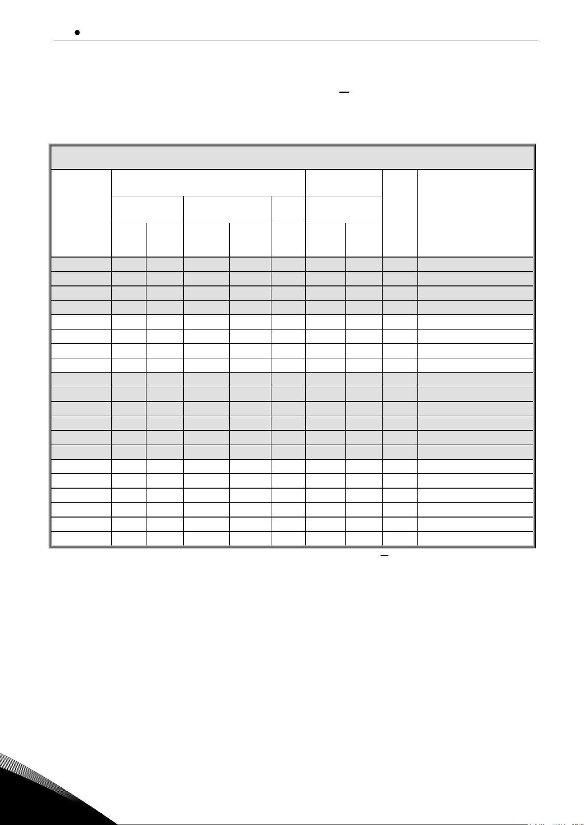
4.2 NX Inverter drive Power ratings
4.2.1
Supply voltage 465-800 Vdc, Motor voltage 380 500 Vac
Table 4-1. Power ratings and dimensions of VACON® NXI, supply voltage 465 800Vdc
Note: The rated currents in given ambient temperatures are achieved only when the switching
frequency is equal to or less than the factory default.
Motor voltage 380-500 Vac, 50/60 Hz, 3~
Inverter type
Loadability
@ 40 °C ambient temperature
Motor shaft power
Enclos
ure
size
Dimensions and weight
W×H×D/kg
Low
High
513Vdc
supply
675Vdc
supply
Rated
continuous
current IL
(A)
10%
overload
current
(A)
Rated
continuous
current
IH (A)
50%
overload
current
(A)
Max
current
I
S
10%
overload
40°C
P(kW)
50%
overload
40°C
P(kW)
10%
overload
40°C
P(kW)
50%
overload
40°C P(kW)
NXI_0168 5
170
187
140
210
238
90
75
110
90
FI9
239 × 1030 × 372/65
NXI_0205 5
205
226
170
255
285
110
90
132
110
FI9
239 × 1030 × 372/65
NXI_0261 5
261
287
205
308
349
132
110
160
132
FI9
239 × 1030 × 372/65
NXI_0300 5
300
330
245
368
444
160
132
200
160
FI9
239 × 1030 × 372/65
NXI_0385 5
385
424
300
450
540
200
160
250
200
FI10
239 × 1030 × 552/100
NXI_0460 5
460
506
385
578
693
250
200
315
250
FI10
239 × 1030 × 552/100
NXI_0520 5
520
572
460
690
828
250
250
355
315
FI10
239 × 1030 × 552/100
NXI_0590 5
590
649
520
780
936
315
250
400
355
FI12
2×239 × 1030 × 552/200
NXI_0650 5
650
715
590
885
1062
355
315
450
400
FI12
2×239 × 1030 × 552/200
NXI_0730 5
730
803
650
975
1170
400
355
500
450
FI12
2×239 × 1030 × 552/200
NXI_0820 5
820
902
730
1095
1314
450
400
560
500
FI12
2×239 × 1030 × 552/200
NXI_0920 5
920
1012
820
1230
1476
500
450
630
560
FI12
2×239 × 1030 × 552/200
NXI_1030 5
1030
1133
920
1380
1656
560
500
710
630
FI12
2×239 × 1030 × 552/200
NXI_1150 5
1150
1265
1030
1545
1854
630
560
800
710
FI13
708 × 1030 × 553/302
NXI_1300 5
1300
1430
1150
1725
2070
710
630
900
800
FI13
708 × 1030 × 553/302
NXI_1450 5
1450
1595
1300
1950
2340
800
710
1000
900
FI13
708 × 1030 × 553/302
NXI_1770 5
1770
1947
1600
2400
2880
1000 1200 FI14
2×708 × 1030 × 553/302
NXI_2150 5
2150
2365
1940
2910
3492
1200 1500
FI14
2×708 × 1030 × 553/302
NXI_2700 5
2700
2970
2300
3287
3933
1500 1800
FI14
2×708 × 1030 × 553/302
18 vacon technical data
Local contacts: https://www.danfoss.com/en/contact-us/contacts-list/
4
4.2.2
Supply voltage 640-1100 Vdc, Motor voltage 525 690 Vac
All enclosures are available as IP21 and IP54.
Motor voltage 525-690 Vac, 50/60 Hz, 3~
Inverter type
Loadability
@ 40 °C ambient temperature
Motor shaft
power
Enclos
ure
size
Dimensions and weight
W×H×D/kg
Low
High
930Vdc
supply
Rated
continuou
s current
IL (A)
10%
overload
current
(A)
Rated
continuous
current
IH (A)
50%
overload
current
(A)
Max
current
I
S
10%
overload
40°C P(kW)
50%
overload
40°C
P(kW)
NXI_0125 6
125
138
100
150
200
110
90
FI9
239 × 1030 × 372/65
NXI_0144 6
144
158
125
188
213
132
110
FI9
239 × 1030 × 372/65
NXI_0170 6
170
187
144
216
245
160
132
FI9
239 × 1030 × 372/65
NXI_0208 6
208
229
170
255
289
200
160
FI9
239 × 1030 × 372/65
NXI_0261 6
261
287
208
312
375
250
200
FI10
239 × 1030 × 552/100
NXI_0325 6
325
358
261
392
470
315
250
FI10
239 × 1030 × 552/100
NXI_0385 6
385
424
325
488
585
355
315
FI10
239 × 1030 × 552/100
NXI_0416 6
416
458
325
488
585
400
355
FI10
239 × 1030 × 552/100
NXI_0460 6
460
506
385
578
693
450
400
FI12
2×239 × 1030 × 552/200
NXI_0502 6
502
552
460
690
828
500
450
FI12
2×239 × 1030 × 552/200
NXI_0590 6
590
649
502
753
904
560
500
FI12
2×239 × 1030 × 552/200
NXI_0650 6
650
715
590
885
1062
630
560
FI12
2×239 × 1030 × 552/200
NXI_0750 6
750
825
650
975
1170
710
630
FI12
2×239 × 1030 × 552/200
NXI_0820 6
820
902
650
975
1170
800
710
FI12
2×239 × 1030 × 552/200
NXI_0920 6
920
1012
820
1230
1476
900
800
FI13
708 × 1030 × 553/302
NXI_1030 6
1030
1133
920
1380
1656
1000
900
FI13
708 × 1030 × 553/302
NXI_1180 6
1180
1298
1030
1464
1755
1200
1000
FI13
708 × 1030 × 553/302
NXI_1500 6
1500
1650
1300
1950
2340
1500
1300
FI14
2×708 × 1030 × 553/302
NXI_1900 6
1900
2090
1500
2250
2700
1800
1500
FI14
2×708 × 1030 × 553/302
NXI_2250 6
2250
2475
1900
2782
3335
2000
1800
FI14
2×708 × 1030 × 553/302
Table 4-2. Power ratings and dimensions of VACON® NXI, supply voltage 640 1100Vdc
Note: The rated currents in given ambient temperatures are achieved only when the switching
frequency is equal to or less than the factory default.
4.2.3
Overload capability
The low overload means that if 110% of the continuous current (IL) is required for 1 minute
every 10 minutes, the remaining 9 minutes must be approximately 98% of IL or less. This is to
make sure that the output current is not more than IL during the duty cycle.

technical data vacon 19
Local contacts: https://www.danfoss.com/en/contact-us/contacts-list/
4
Figure 4-2. Low overload
The high overload means that if 150% of the continuous current (IH) is required for 1 minute
every 10 minutes, the remaining 9 minutes must be approximately 92% of IH or less. This is
to make sure that the output current is not more than IH during the duty cycle.
Figure 4-3. High overload
20 vacon technical data
Local contacts: https://www.danfoss.com/en/contact-us/contacts-list/
4
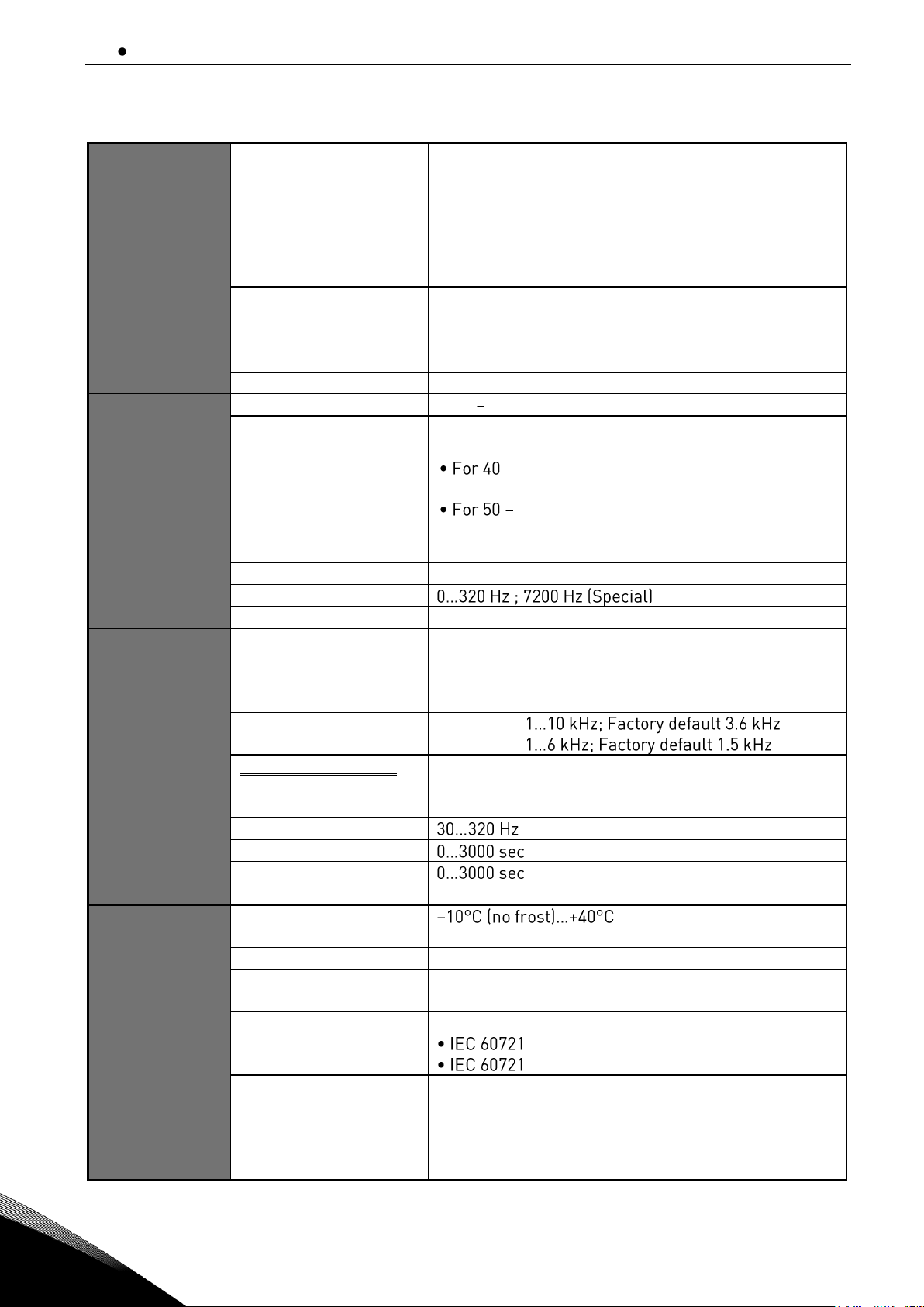
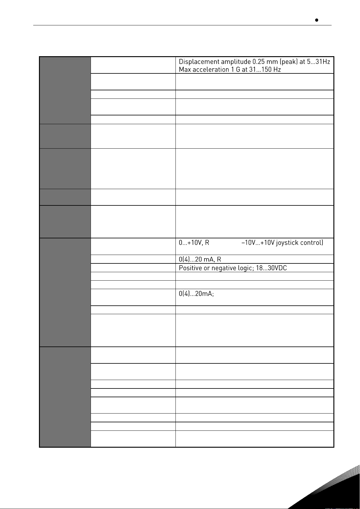
4.3 Technical information
Supply
connection
Input voltage Uin
465...800Vdc ( 380-500 Vac)
640...1100Vdc ( 525-690 Vac)
The waviness of the inverter supply voltage, which is
formed in rectification of the electric network's
alternating voltage in basic frequency, must be less
than 50V peak-to-peak.
Input current I
in
(sqrt3 × U
mot
× I
mot
× cos) / ( Uin × 0.98)
DC bank capacitance
FI9_5 : 4950F; FI9_6 : 3733F
FI10_5: 9900F; FI10_6: 7467F
FI12_5: 19800F; FI12_6: 14933F
FI13_5: 29700F; FI13_6: 22400F
Starting delay
5 s (FI9 and greater)
Motor
connection
Output voltage
3 ~ 0 Uin / 1.4
Continuous output
current
IH: Ambient temperature +40 °C (104 °F),
overloadability 1.5 x IH (1 min./10 min.).
- 50 °C (104 - 122°F), the ambient
temperatures use derating factor IH*1.5%/1 °C (°F).
55 °C (122 - 131°F), the ambient
temperatures use derating factor IH*2.5% /1 °C (°F).
Starting torque
IS for two seconds, torque motor dependent
Peak current
IS for 2 s every 20 s
Output frequency
Frequency resolution
Application dependent
Control
characteristics
Control method
Frequency control U/f
Open Loop Sensorless Vector Control
Closed Loop Frequency Control
Closed Loop Vector Control
Switching frequency
(see parameter 2.6.9)
NXI_5:
NXI_6:
Frequency reference
Analogue input
Panel reference
Resolution 0.1% (12-bit), accuracy ±1%
Resolution 0.01 Hz
Field weakening point
Acceleration time
Deceleration time
Braking torque
DC brake: 30% * TN (without brake)
Ambient
conditions
Ambient operating
temperature
Storage temperature
-40 °C (-40 °F)...+70 °C (158 °F)
Relative humidity
0 to 95% RH, non-condensing, non-corrosive,
no dripping water
Air quality:
- chemical fumes
- solid particles
Designed according to
-3-3, AC drive in operation, class 3C2
-3-3, AC drive in operation, class 3S2
Altitude
100% loadability (no derating) up to 1000 m.
Maximum elevation 2000 m (525-690 VAC) and 4000
m (380-500 VAC), Relay I/O: max. 240 V: 3000 m;
max. 120 V: 4000 m, see Power derating as a
function of installation altitude. See Chapter 4.4.
technical data vacon 21
Local contacts: https://www.danfoss.com/en/contact-us/contacts-list/
4
Vibration
EN50178/EN60068-2-6
Shock
EN50178, EN60068-2-27
UPS Drop Test (for applicable UPS weights)
Storage and shipping: max 15 G, 11 ms (in package)
Heat loss
P
loss
[kW] approx. P
mot
[kW] × 0.02
Cooling air required
FI9 1150 m3/h, FI10 1400 m3/h,
FI12 2800 m3/h, FI13 4200 m3/h, FI14 2×4200 m3/h
Unit enclosure class
IP00/Open type standard size in the kW/HP range
EMC
(at default
settings)
Immunity
IEC/EN 61800-3:2004+A1:2012, second
environment
Noise level
Average noise level
(cooling fan) in dB(A)
FI9: 76
FI10: 74
FI12: 76
FI13: 81
FI14: 2*81 (2*FI13)
Safety
standards
IEC/EN 61800-5-1, UL 508C, CSA C22.2 No.274
T-level, see chapter 2.2.3.
Approvals
CE, cULus, RCM, KC, EAC, UA. (See the nameplate
of the drive for more approvals.)
Marine approvals: LR, BV, DNV, GL, ABS, RMRS,
CCS,KR.
Control
connections
Analogue input voltage
i
= 200k, (
Resolution 0.1%, accuracy ±1%
Analogue input current
i
= 250 differential
Digital inputs (6)
Auxiliary voltage
+24V, ±15%, max. 250mA
Output reference voltage
+10V, +3%, max. load 10mA
Analogue output
RL max. 500; Resolution 10 bit;
Accuracy ±2%
Digital outputs
Open collector output, 50mA/48V
Relay outputs
2 programmable change-over relay outputs
Switching capacity: 24VDC/8A, 250VAC/8A,
125VDC/0.4A
Min.switching load: 5V/10mA
Protections
Overvoltage protection
Undervoltage protection
NX_5: 911VDC; NX_6: 1200VDC
NX_5: 333VDC; NX_6: 461 VDC
Earth fault protection
In case of earth fault in motor or motor cable, only
the inverter is protected
Motor phase supervision
Trips if any of the output phases is missing
Overcurrent protection
Yes
Unit overtemperature
protection
Yes
Motor overload protection
Yes
Motor stall protection
Yes
Motor underload
protection
Yes

22 vacon technical data
Local contacts: https://www.danfoss.com/en/contact-us/contacts-list/
4
Short-circuit protection of
+24V and +10V reference
voltages
Yes
Table 4-3. Technical information
technical data vacon 23
Local contacts: https://www.danfoss.com/en/contact-us/contacts-list/
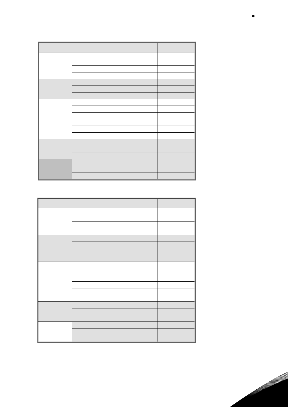
4
Structure
IN (output)
Motor P.F.
IDC (input)
FI9
170
0.89
198
205
0.89
239
261
0.89
304
300
0.89
350
FI10
385
0.9
454
460
0.9
542
520
0.9
613
FI12
590
0.9
695
650
0.9
766
730
0.91
870
820
0.91
977
920
0.91
1096
1030
0.91
1227
FI13
1150
0.91
1370
1300
0.91
1549
1450
0.91
1727
FI14
1770
0.92
2132
2150
0.92
2590
2700
0.92
3252
Table 4- 4 DC currents and dimensions of VACON® NXI, supply voltage 465 - 800Vdc
Structure
IN (output)
Motor P.F.
IDC (input)
FI9
125
0.89
146
144
0.89
168
170
0.89
198
208
0.9
245
FI10
261
0.9
308
325
0.9
383
385
0.9
454
416
0.9
490
F12
460
0.91
548
502
0.91
598
590
0.91
703
650
0.91
774
750
0.91
894
820
0.91
977
FI13
920
0.91
1096
1030
0.91
1227
1180
0.92
1421
FI14
1500
0.92
1807
1900
0.93
2313
2250
0.93
2739
Table 4- 5. DC currents and dimensions of VACON® NXI, supply voltage 640 - 1100Vdc
4.4 Derating
The output power has to be derated if one of following cases:

24 vacon technical data
Local contacts: https://www.danfoss.com/en/contact-us/contacts-list/
4
4.4.1
Ambient temperature
The power rating of the Active Front End unit is valid for an ambient temperature of 40 ºC (104 °F). If
the device is to be used in higher ambient temperatures, its power rating must be subjected to
derating. The derating coefficient from 40 °C to 50 °C, use derating factor 1.5 %/1 °C, and from 50 °C
to 55 °C, use derating factor 2.5 %/1 °C, for ambient temperatures not exceeding 55 °C (131 °F). The
reduced power is calculated using the formula:
Pde = Pn *((100% - (t - 40 ºC)*X)/100)
Pn = nominal power of the unit
t = ambient temperature
x = derating coefficient
C
11167A_00
0
10
20
30
40
50
60
0%
20%
40%
60%
80%
100%
120%
B
A
A
Ambient temperature, °C
B
Loadability, %
C
Loadability %
Figure 4-4. Derating as the ambient temperature
4.4.2
High altitude installation
The density of air decreases when the altitude increases and the pressure decreases. When the air
density decreases, the thermal capacity decreases (i.e. less air removes less heat) and the
resistance to electric field (breakdown voltage / distance) decreases.

technical data vacon 25
Local contacts: https://www.danfoss.com/en/contact-us/contacts-list/
4
The full thermal performance of VACON® NX AC drives is designed for installation up to 1000 m
altitude and the electric insulation is designed for installations up to 2000 m altitude. Higher
installation locations are possible, when you obey the derating guidelines in this chapter.
NOTE! 690V units maximum installation altitude is 2000m.
Above 1000 m, you must decrease the limited maximum load current by 1% for each 100 m. Thus, for
example, at 2500 m altitude, you must decrease the load current down to 85% of the rated output
current (100% (2500 m 1000 m) / 100 m x 1% = 85%).
When you use fuses at high altitudes, the cooling effect of the fuse decreases as the density of the
atmosphere decreases.
When you use fuses above 2000 meters, the continuous rating of the fuse:
I = In*(1- (h-2000)/100*0.5/100)
I = Current rating at high altitude
In = Rated current of a fuse
h = Altitude in meters
0
500
1000
1500
2000
2500
3000
3500
4000
4500
5000
0%
10%
30%
50%
70%
20%
40%
60%
80%
90%
100%
110%
A
Figure 4-5. Loadability in high altitudes
For permitted maximum altitudes, see Table 7.
For information on option boards and I/O signals and relay outputs, see VACON® NX I/O Boards
User Manual.

26 vacon installation
Local contacts: https://www.danfoss.com/en/contact-us/contacts-list/
5
5. INSTALLATION
5.1 Mounting
The inverter can be mounted in a vertical position on the back plane of a cubicle. Enough space must
be reserved around the inverter to ensure sufficient cooling, see Figure 5-7. Follow the minimum
dimensions for installation, see Table 5-1 and Table 5-2. Also make sure that the mounting plane is
relatively even. The inverter is fixed with four screws (or bolts, depending on the unit size). The
dimensions for installation are presented in Figure 5-7 and Table 5-1.The following pages show the
dimensions for IP00 power module.
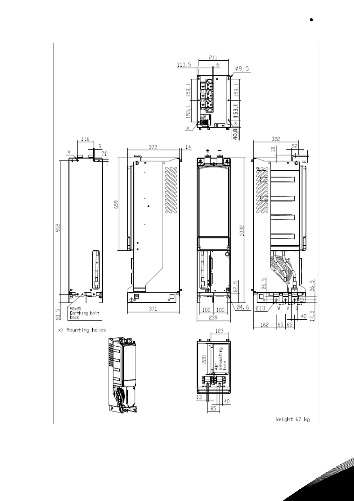
installation vacon 27
Local contacts: https://www.danfoss.com/en/contact-us/contacts-list/
5
Figure 5-1. The dimensions of VACON® NXI FI9
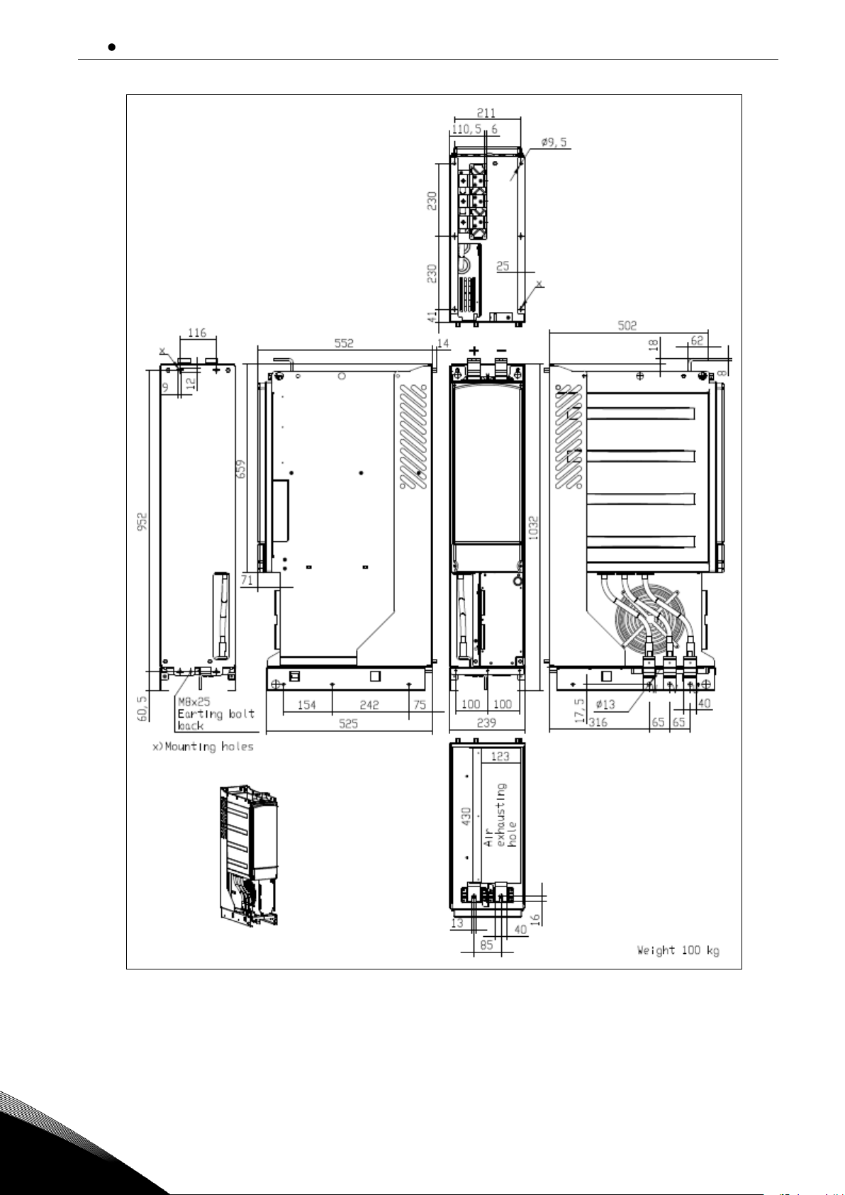
28 vacon installation
Local contacts: https://www.danfoss.com/en/contact-us/contacts-list/
5
Figure 5-2. VACON® NXI dimensions, FI10
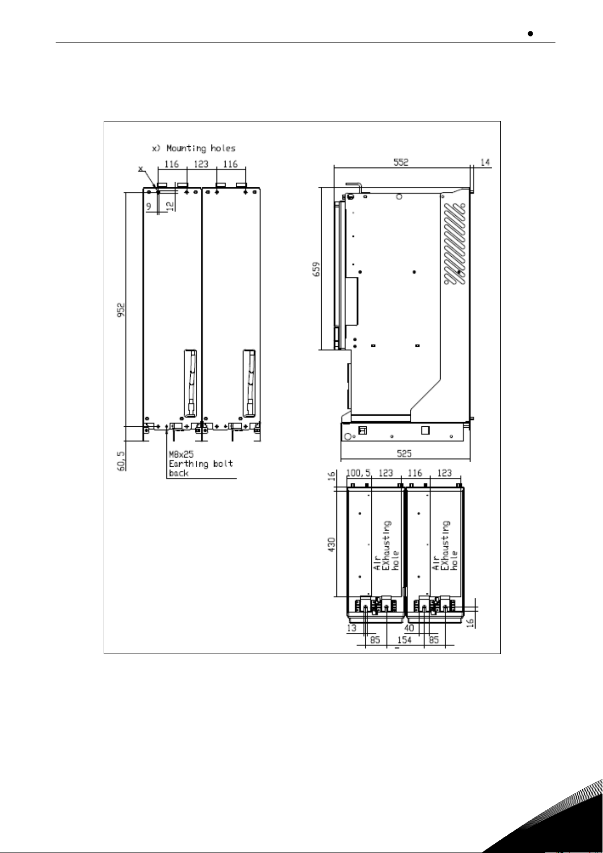
installation vacon 29
Local contacts: https://www.danfoss.com/en/contact-us/contacts-list/
5
Figure 5-3. VACON® NXI dimensions, FI12 back view.

30 vacon installation
Local contacts: https://www.danfoss.com/en/contact-us/contacts-list/
5
Figure 5-4. VACON® NXI dimensions, FI12 front view
 Loading...