

Page 1

vacon
ac drives
®
nx
active front end ii (afe-ii)
arfiff05
application manual
Page 2

Page 3

Arfiff05 Standard AFE-II vacon • 3
Local contacts: http://drives.danfoss.com/danfoss-drives/local-contacts/
Vacon Standard AFE-II application
INDEX
Document code: DPD01979A
Software code: ARFIFF05V051
Date: 23.3.2018
VACON STANDARD AFE-II APPLICATION .......................................................................................3
1. Introduction ...................................................................................................................................................................................... 6
1.1 Compatibili ty issues in parameters between versions.................................................................................................... 7
2. AFE Units ........................................................................................................................................................................................... 8
2.1 500 Vac units Air Cooled, 465 -800 Vdc .............................................................................................................................. 8
2.2 690 Vac units Air Cooled, 640 -1100 Vdc............................................................................................................................ 8
2.3 500 Vac units Liquid-Cool ed, 465-800 Vdc........................................................................................................................ 9
2.4 690 Vac units Liquid-Cool ed, 640-1100 Vdc...................................................................................................................... 9
2.5 690 Vac units Liquid –Cooled, 640-1200 Vdc.................................................................................................................. 10
3. Operation ........................................................................................................................................................................................ 11
3.1 Charging of DC ...................................................................................................................................................................... 11
3.2 Mai n Circuit breaker control (MCB control ) ................................................................................................................... 11
3.3 Quick Start instructions ...................................................................................................................................................... 12
3.4 Start Sequ ence ..................................................................................................................................................................... 13
3.5 Stop Sequence ...................................................................................................................................................................... 14
3.6 Start Stop timing diagram .................................................................................................................................................. 15
4. CONTROL IO .................................................................................................................................................................................... 16
5. AFE Application – Monitoring Values ....................................................................................................................................... 17
5.1 Monitoring values ................................................................................................................................................................ 18
5.1.1 Monitoring 1 .................................................................................................................................................................... 18
5.1.2 FieldBus Moni toring values ........................................................................................................................................... 18
5.1.3 Line Monitor OPT-D7 ...................................................................................................................................................... 18
5.1.4 Master Follower .............................................................................................................................................................. 19
5.1.5 Monitoring values 2 ........................................................................................................................................................ 19
5.2 Monitoring Values description .......................................................................................................................................... 19
5.2.1 Monitoring 1 values ........................................................................................................................................................ 19
5.2.2 Fieldbus moni toring values ........................................................................................................................................... 21
5.2.3 Line monitoring OPT-D7................................................................................................................................................. 26
5.2.4 Master/Follower.............................................................................................................................................................. 26
5.2.5 Monitoring values 2 ........................................................................................................................................................ 27
6. Parameter List................................................................................................................................................................................ 28
6.1 Basi c parameters.................................................................................................................................................................. 28
6.2 Reference Handling ............................................................................................................................................................. 28
6.3 Input signals .......................................................................................................................................................................... 29
6.3.1 Digi tal inputs .................................................................................................................................................................... 29
6.3.2 Analogue Input 1 ............................................................................................................................................................. 29
6.3.3 Analogue Input 2 ............................................................................................................................................................. 29
6.3.4 Cabi n State DI................................................................................................................................................................... 30
6.3.5 Options.............................................................................................................................................................................. 30
6.4 Output signals....................................................................................................................................................................... 31
6.4.1 Digi tal Outputs................................................................................................................................................................. 31
6.4.2 ANALOG OUTPUT 1 ......................................................................................................................................................... 31
Page 4

4 • Vacon arfiff05 Standard AFE-II
Local contacts: http://drives.danfoss.com/danfoss-drives/local-contacts/
6.4.3 Options.............................................................................................................................................................................. 32
6.5 Limit Settings ........................................................................................................................................................................ 33
6.5.1 Current Limit .................................................................................................................................................................... 33
6.5.2 Power Limit ...................................................................................................................................................................... 33
6.5.3 Frequency Limit ............................................................................................................................................................... 33
6.5.4 AC Voltage Limit .............................................................................................................................................................. 33
6.5.5 DC Voltage Limi t .............................................................................................................................................................. 33
6.6 Dri ve Control parameters ................................................................................................................................................... 34
6.6.1 Control............................................................................................................................................................................... 34
6.7 Protections ............................................................................................................................................................................ 35
6.7.1 Gen eral.............................................................................................................................................................................. 35
6.7.2 Temperature sensor protections.................................................................................................................................. 35
6.7.3 Fieldbus ............................................................................................................................................................................. 36
6.7.4 OPT-D7 protections ........................................................................................................................................................ 36
6.7.5 Options.............................................................................................................................................................................. 36
6.8 Fieldbus parameters ............................................................................................................................................................ 37
6.9 ID Control Functi ons............................................................................................................................................................ 38
6.9.1 Value control.................................................................................................................................................................... 38
6.9.2 DIN ID Control 1............................................................................................................................................................... 38
6.10 Keypad control (Control keypad: Menu M3) .................................................................................................................. 39
6.11 System menu (Control keypad: Menu M6) ..................................................................................................................... 39
6.12 Expander boards (Control keypad: Menu M7) ............................................................................................................... 39
7. Description of parameters .......................................................................................................................................................... 40
7.1 Basi c parameters.................................................................................................................................................................. 40
7.2 Reference Handling ............................................................................................................................................................. 41
7.3 Input signals .......................................................................................................................................................................... 42
7.3.1 Digi tal inputs .................................................................................................................................................................... 42
7.3.2 Analogue Inputs............................................................................................................................................................... 44
7.3.3 Cabi n State DI................................................................................................................................................................... 47
Options .................................................................................................................................................................................. 47
7.3.4.................................................................................................................................................................................................. 47
7.4 Output signals....................................................................................................................................................................... 48
7.4.1 Digi tal outputs ................................................................................................................................................................. 48
7.4.2 Analogue outputs ............................................................................................................................................................ 50
7.4.3 Options outputs............................................................................................................................................................... 52
7.5 Limit Settings ........................................................................................................................................................................ 53
7.5.1 Current limi ts ................................................................................................................................................................... 53
7.5.2 Power Limits ..................................................................................................................................................................... 53
7.5.3 Frequency limits .............................................................................................................................................................. 53
7.5.4 AC Voltage li mits ............................................................................................................................................................. 54
7.5.5 DC Voltage limit parameters ......................................................................................................................................... 55
7.6 Dri ve control ......................................................................................................................................................................... 56
7.6.1 Control............................................................................................................................................................................... 58
7.7 Protections ............................................................................................................................................................................ 60
7.7.1 Gen eral.............................................................................................................................................................................. 60
7.7.2 Temperature sensor protections.................................................................................................................................. 61
7.7.3 Fieldbus ............................................................................................................................................................................. 62
7.7.4 OPT-D7 Protections......................................................................................................................................................... 63
7.8 Fieldbus parameters............................................................................................................................................................ 64
7.9 ID Functions .......................................................................................................................................................................... 65
7.9.1 Value Control ................................................................................................................................................................... 65
7.9.2 DIN ID Control .................................................................................................................................................................. 67
7.10 Keypad control ..................................................................................................................................................................... 68
8. Status and control words in detail ............................................................................................................................................ 69
8.1 Basi c In ByPass (0)................................................................................................................................................................ 69
Page 5

Arfiff05 Standard AFE-II vacon • 5
Local contacts: http://drives.danfoss.com/danfoss-drives/local-contacts/
8.2 FB Control Word................................................................................................................................................................... 70
8.2.1 Standard (1)...................................................................................................................................................................... 70
8.2.2 Vacon AFE 1 profile (2) ................................................................................................................................................... 71
8.2.3 Vacon AFE 2 Profile (3) ................................................................................................................................................... 73
8.3 FB Status Word..................................................................................................................................................................... 75
8.4 Fault Word 1 ......................................................................................................................................................................... 77
8.5 Fault Word 2 ......................................................................................................................................................................... 77
8.6 Warning Word 1................................................................................................................................................................... 78
8.7 Auxiliary Control Word ....................................................................................................................................................... 79
8.8 Status Word (Application) ID 43........................................................................................................................................ 80
9. Problem Solving ............................................................................................................................................................................. 82
10. Fault codes................................................................................................................................................................................. 83
Page 6
6 • Vacon arfiff05 Standard AFE-II
Local contacts: http://drives.danfoss.com/danfoss-drives/local-contacts/
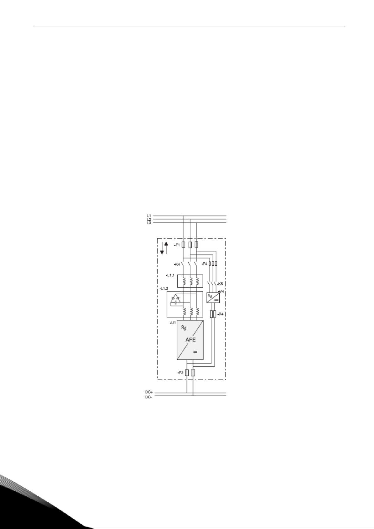
1. INTRODUCTION
The AFE unit is a regenerative power converter for the front-end of a common DC bus product line.
The AFE unit is utilized by using inverter hardware with special software. An external L(CL)-filter
and charging circuit is needed. This unit is selected when low harmonics are required. The principle
connection of AFE drive has been described in Figure 1.
The Regenerative Application is easy and flexible to use due to its versatile fieldbus features. The
parameters of the Regenerative Application are explained in Chapter 7 of this manual.
The basic I/O-configuration of the AFE drive consists of OPT-A1 and OPT-A2 option cards. The basic
I/O configuration has been described in table 2-1.
As a default the control place (P3.1) of the AFE drive is Keypad.
This application requires NXP3 control board VB00761.
Figure 1, AFE connection
Page 7

Arfiff05 Standard AFE-II vacon • 7
Local contacts: http://drives.danfoss.com/danfoss-drives/local-contacts/
1.1 Compatibility issues in parameters between versions
V025
• Compatibility Issue: MCB Force Open inverted. This to follow NXC cabinet
default signals.
Update Note 1: This application parameters are not kept backwards compatible if new features or
improvements would be difficult to implement by doing so. Read this change note and chapter
Compatibility issues in parameters between versions before updating the application.
Update Note 2:
application, especially in cases when version number change is considerably high.
Application is constantly developed; this includes changing parameter default values, and if
parameters are directly downloaded to drive improved default values may be lost.
Page 8
8 • Vacon arfiff05 Standard AFE-II
Local contacts: http://drives.danfoss.com/danfoss-drives/local-contacts/
2. AFE UNITS
Air and liquid-cooled products listed in chapter 2 are compatible with AFE application ARFIFF05.
Hardware and software support for AFE use is only available for these products.
Downloading AFE application to products other than those listed in chapter 2 is considered to be a
non-standard product which functionality has not been verified or documented. In such cases User
takes full responsibility for possible hardware and software problems. Application support is not
available for non-standard products.
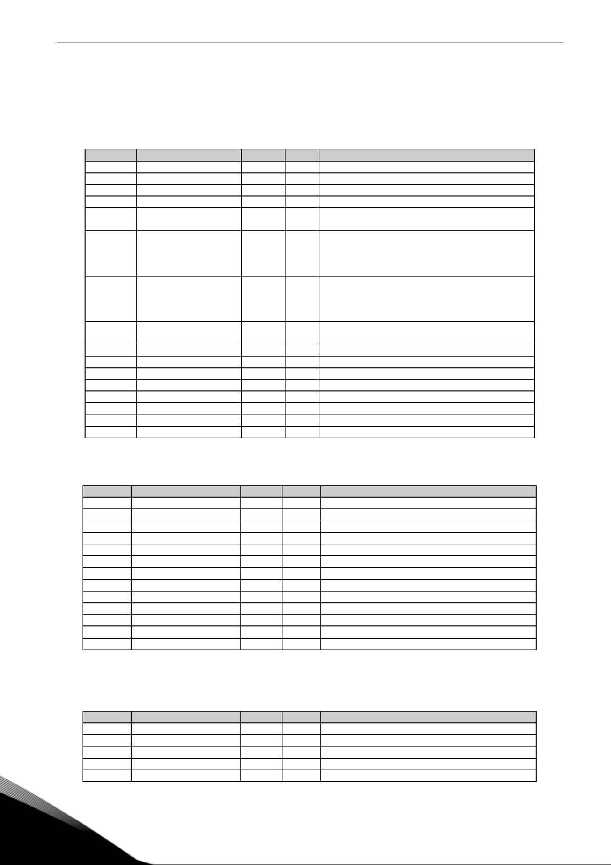
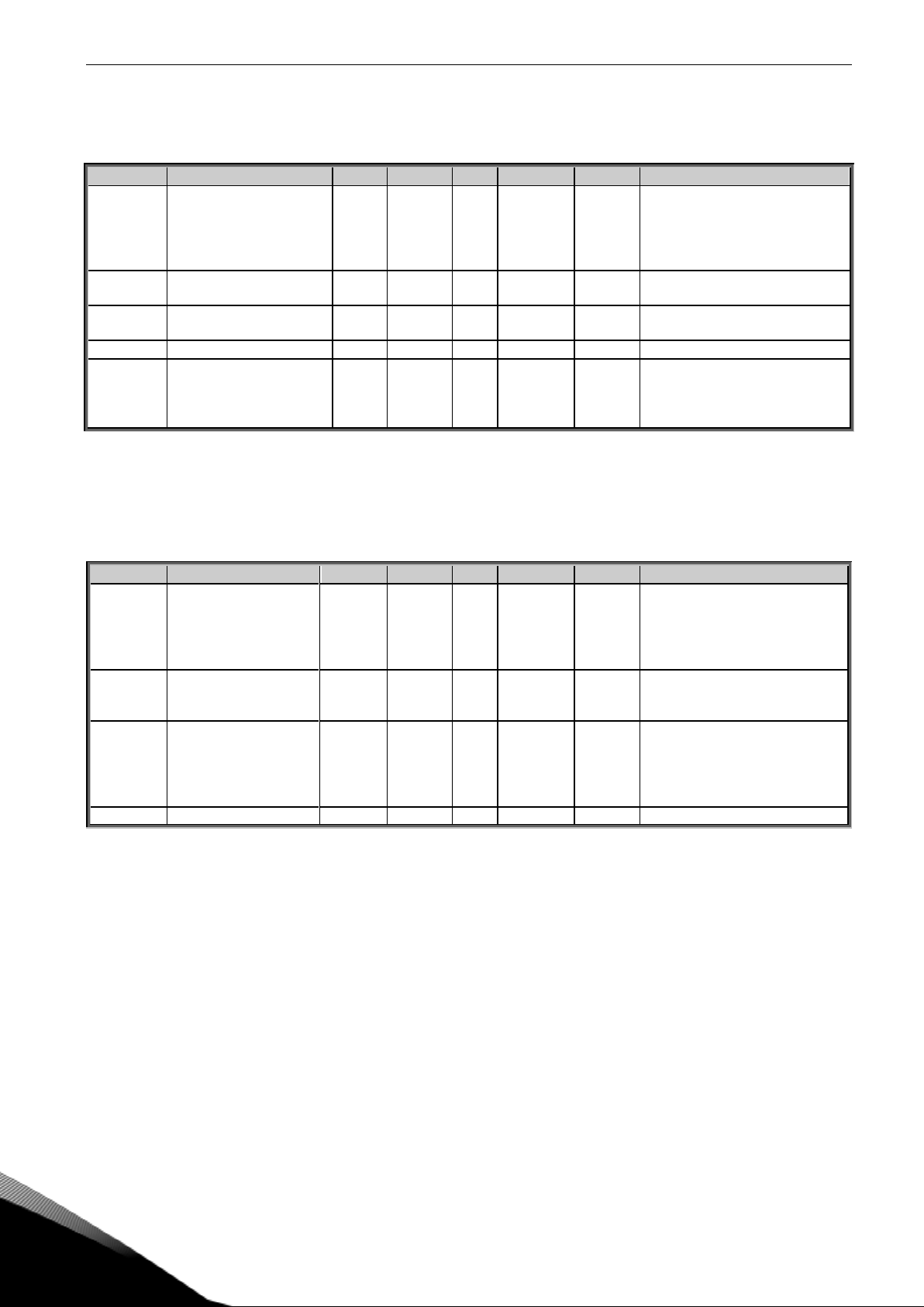
2.1 500 Vac units Air Cooled, 465-800 Vdc
Code
Frame
IL-cont [A]
IH-cont
[A]
NXA_0168 5 A0T02SG
FI9
170
140
NXA_0205 5 A0T02SG
FI9
205
170
NXA_0261 5 A0T02SG
1xFI9
261
205
NXA_0385 5 A0T02SG
1xFI10
385
300
NXA_0460 5 A0T02SG
1xFI10
460
385
NXA_1150 5 A0T02SG
1xFI13
1150
1030
NXA_1300 5 A0T02SG
1xFI13
1300
1150
2.2 690 Vac units Air Cooled, 640-1100 Vdc
Code
Frame
IL-cont [A]
IH-cont
[A]
NXA_0125 6 A0T02SG
1xFI9
125
100
NXA_0144 6 A0T02SG
1xFI9
144
125
NXA_0170 6 A0T02SG
1xFI9
170
144
NXA_0261 6 A0T02SG
1xFI10
261
208
NXA_0325 6 A0T02SG
1xFI10
325
261
NXA_0920 6 A0T02SG
1xFI13
920
820
NXA_1030 6 A0T02SG
1xFI13
1030
920
Page 9
Arfiff05 Standard AFE-II vacon • 9
Local contacts: http://drives.danfoss.com/danfoss-drives/local-contacts/
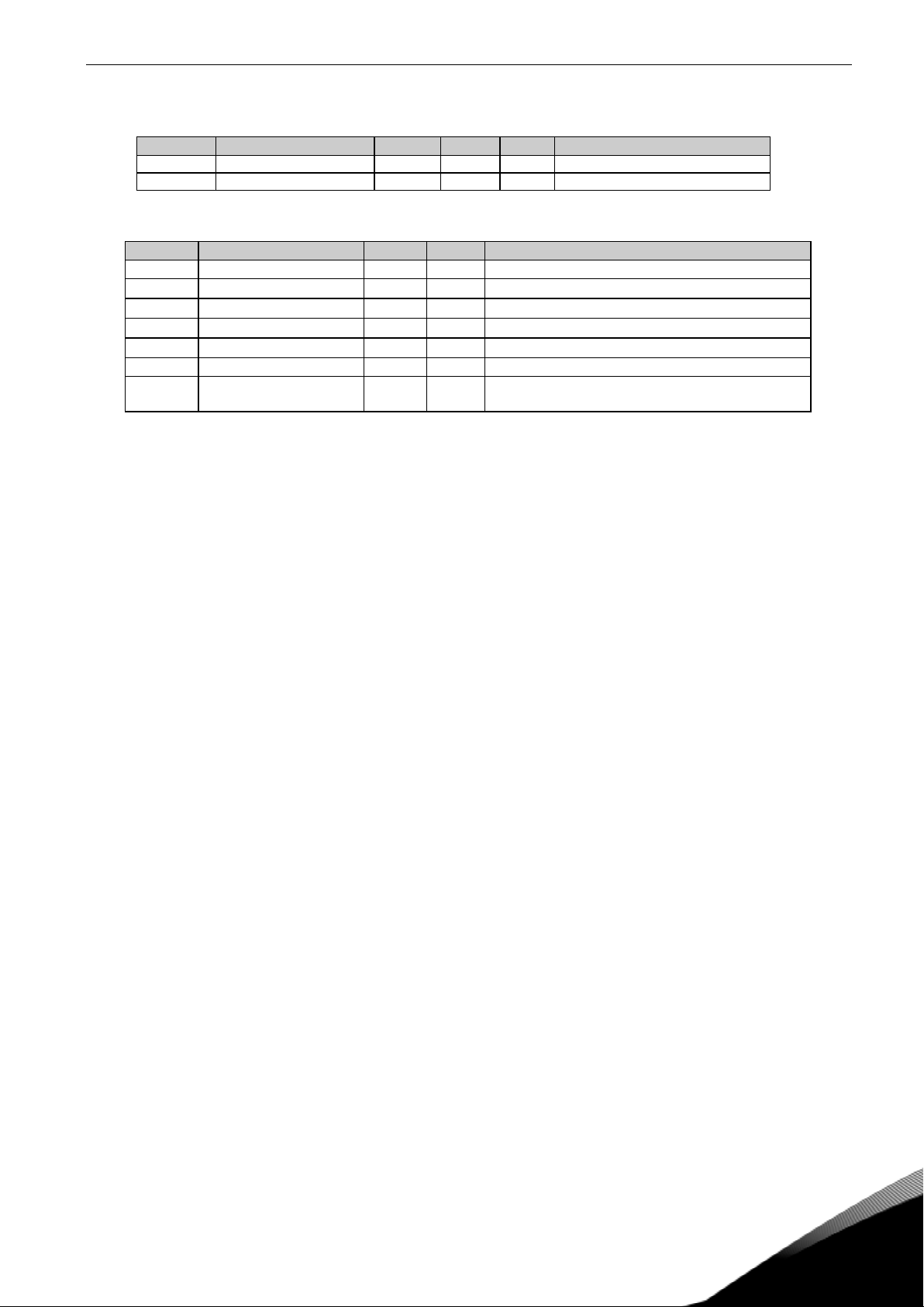
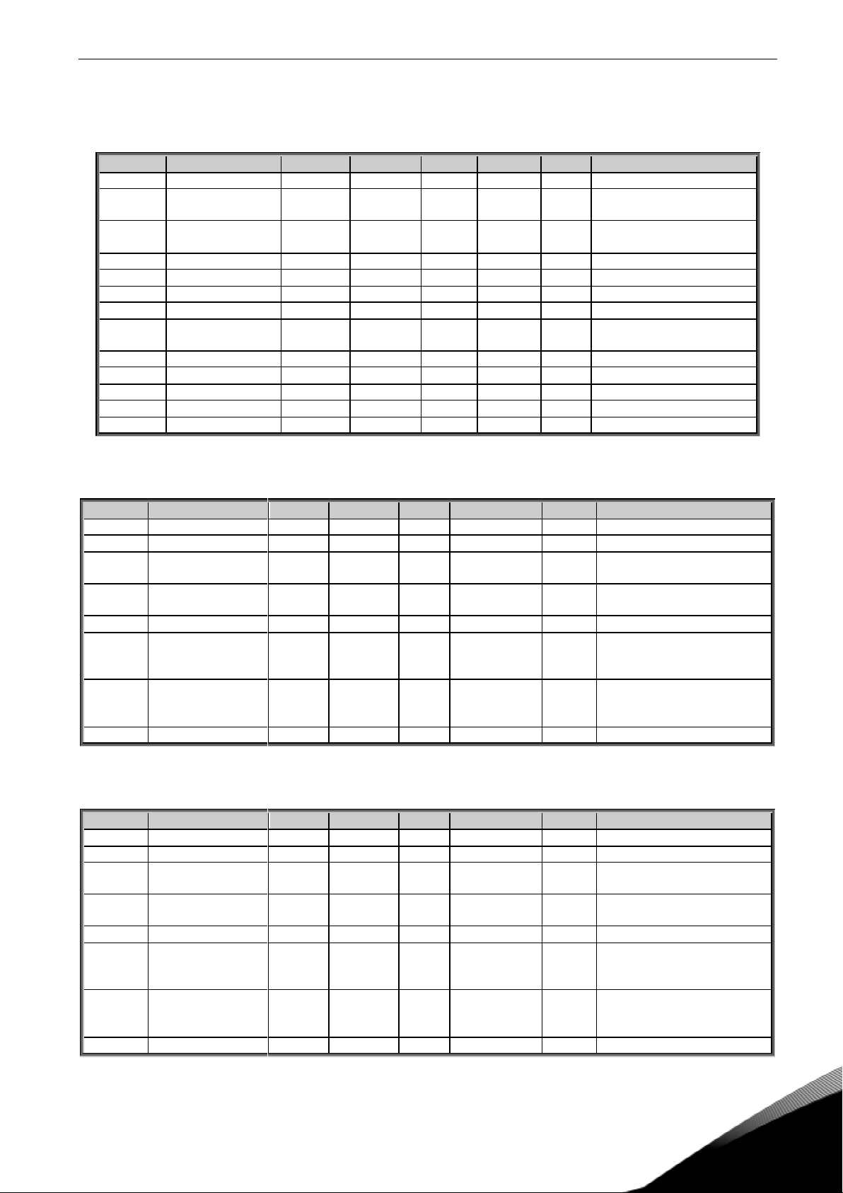
2.3 500 Vac units Liquid-Cooled, 465-800 Vdc
Code
Chassis
Ith [A]
Il [A]
Ih [A]
NXA01685A0T02WS
CH5
168
153
112
NXA02055A0T02WS
CH5
205
186
137
NXA02615A0T02WS
CH5
261
237
174
NXA03005A0T02WF
CH61
300
273
200
NXA03855A0T02WF
CH61
385
350
257
NXA04605A0T02WF
CH62
460
418
307
NXA05205A0T02WF
CH62
520
473
347
NXA05905A0T02WF
CH62
590
536
393
NXA06505A0T02WF
CH62
650
591
433
NXA07305A0T02WF
CH62
730
664
487
NXA08205A0T02WF
CH63
820
745
547
NXA09205A0T02WF
CH63
920
836
613
NXA10305A0T02WF
CH63
1030
936
687
NXA11505A0T02WF
CH63
1150
1045
767
NXA13705A0T02WF
CH64
1370
1245
913
NXA16405A0T02WF
CH64
1640
1491
1093
NXA20605A0T02WF
CH64
2060
1873
1373
NXA23005A0T02WF
CH64
2300
2091
1533
2.4 690 Vac units Liquid-Cooled, 640-1100 Vdc
Code
Chassis
Ith [A]
Il [A]
Ih [A]
NXA01706A0T02WF
CH61
170
155
113
NXA02086A0T02WF
CH61
208
189
139
NXA02616A0T02WF
CH61
261
237
174
NXA03256A0T02WF
CH62
325
295
217
NXA03856A0T02WF
CH62
385
350
257
NXA04166A0T02WF
CH62
416
378
277
NXA04606A0T02WF
CH62
460
418
307
NXA05026A0T02WF
CH62
502
456
335
NXA05906A0T02WF
CH63
590
536
393
NXA06506A0T02WF
CH63
650
591
433
NXA07506A0T02WF
CH63
750
682
500
NXA08206A0T02WF
CH64
820
745
547
NXA09206A0T02WF
CH64
920
836
613
NXA10306A0T02WF
CH64
1030
936
687
NXA11806A0T02WF
CH64
1180
1073
787
NXA13006A0T02WF
CH64
1300
1182
867
NXA15006A0T02WF
CH64
1500
1364
1000
NXA17006A0T02WF
CH64
1700
1545
1133
Page 10
10 • Vacon arfiff05 Standard AFE-II
Local contacts: http://drives.danfoss.com/danfoss-drives/local-contacts/
2.5 690 Vac units Liquid Cooled, 640-1200 Vdc
Code
Chassis
Ith [A]
Il [A]
Ih [A]
NXA01708A0T02WFA1A2
CH61
170
155
113,0
NXA02088A0T02WFA1A2
CH61
208
189
139,0
NXA02618A0T02WFA1A2
CH61
261
237
174,0
NXA03258A0T02WFA1A2
CH62
325
295
217,0
NXA03858A0T02WFA1A2
CH62
385
350
257,0
NXA04168A0T02WFA1A2
CH62
416
378
277,0
NXA04608A0T02WFA1A2
CH62
460
418
307,0
NXA05028A0T02WFA1A2
CH62
502
456
335,0
NXA05908A0T02WFA1A2
CH63
590
536
393,0
NXA06508A0T02WFA1A2
CH63
650
591
433,0
NXA07508A0T02WFA1A2
CH63
750
682
500,0
NXA08208A0T02WFA1A2
CH64
820
745
547,0
NXA09208A0T02WFA1A2
CH64
920
836
613,0
NXA10308A0T02WFA1A2
CH64
1030
936
687,0
NXA11808A0T02WFA1A2
CH64
1180
1073
787,0
NXA13008A0T02WFA1A2
CH64
1300
1182
867,0
NXA15008A0T02WFA1A2
CH64
1500
1364
1000,0
NXA17008A0T02WFA1A2
CH64
1700
1545
1133,0
Page 11

Arfiff05 Standard AFE-II vacon • 11
Local contacts: http://drives.danfoss.com/danfoss-drives/local-contacts/
3. OPERATION
3.1 Charging of DC
This AFE application has own charging control, P2.4.1.9 DC Charge (24 Vdc required for control
board) level
within set time P2.7.1.5 Charge Max Time (provided that DC Voltage reach at least drive under
voltage fault level).
Charging function is activated when P2.4.1.9 DC Charge is A.1 or higher. When control place is IO,
Keypad or NCDrive charging is started from start command.
Charging is not started if:
- Drive is in fault state.
- P2.3.1.2 Enable MCB Close is FALSE
- P2.3.1.6 Run Enable is FALSE
- P2.3.1.7 Quick Stop is FALSE
Charging is also stopped if above conditions happens during charging or start command is removed.
For fieldbus control charging is started with B0 of FB Control Word on supporting FB profiles.
Charging is also stopped if B0 goes low as is MCB opened if already closed.
DC Charge (F80) is given if 85 % of DC Nominal is not reached within P2.7.1.5 Charge Max Time and
charging is stopped.
DC Charging is stopped when drive receives feedback from P2.3.1.5 MCB Status.
Note! Use suitably sized DC Charging resistor by checking Pulse loadability for time duration set in
for Max Charge Time parameter
3.2 Main Circuit breaker control (MCB control)
The AFE application controls the MCB of the system with Relay Output RO2. When charging of the DC
bus is ready the MCB will be closed. The status of the MCB is monitored via digital input P2.3.1.5
MCB Status (Default is DigIn: A.4). MCB feedback is required for correct AFE functionality,
NOTE! MCB feedback is required for correct AFE functionality.
Over Current (F1), Hardware IGBT (F31) and Software IGBT (F41) faults will open MCB immediately.
Some fault can be programmed to open MCB if needed.
NOTE! For correct operation of AFE system, AFE unit needs to be in control of charging circuit and
Main Circuit Breaker (MCB).
Page 12
12 • Vacon arfiff05 Standard AFE-II
Local contacts: http://drives.danfoss.com/danfoss-drives/local-contacts/
3.3 Quick Start instructions
NOTE! Before taking any commissioning actions read carefully the safety instructions in Vacon NX
User's Manual, chapter 1.
1. Connect the unit according to the Figure 1.
2. Power up the control unit.
3. Set parameters in G2.1 Basic Parameters.
4. Check that digital input parameters (G2.3.1) have been set according to connections. Note
that P2.3.1.5 MCB Status input is needed for correct operation of AFE unit.
5. Check the control place accordingly proves requirements (P3.1 Control Place).
6. Charge DC.
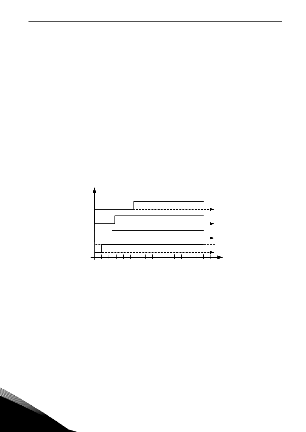
In case of parallel AFE:
1. Set Parallel AFE parameter (P2.1.5) = YES (in every AFE). (This will set also DC Drooping to
4,00 %
2. Set Start Up Delay in AFE units so that starting is in sequence with different intervals.
Time * 100 ms
Stop
AFE 1
Run
Stop
AFE 2
Run
Stop
AFE 3
Run
Stop
AFE 4
Run
Page 13
Arfiff05 Standard AFE-II vacon • 13
Local contacts: http://drives.danfoss.com/danfoss-drives/local-contacts/
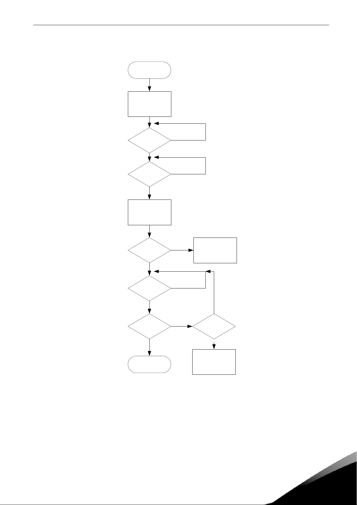
3.4 Start Sequence
Init
Ready to
switch on
DC > 85 %
Close MCB
MCB close
enable
MCB Closed
Start
Command
Synchronized Trials >= 5
Modulating
F10: LineSynch
No
Yes
No
Yes
Yes
Yes
Yes
No
No
No
No
Yes
F64 A2
(Delayed)
Figure 0-2. AFE start sequence
Page 14
14 • Vacon arfiff05 Standard AFE-II
Local contacts: http://drives.danfoss.com/danfoss-drives/local-contacts/
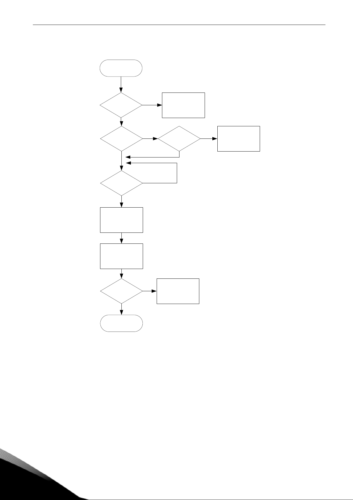
3.5 Stop Sequence
Modulating
MCB Closed
No
F64 A4
Open MCB
No
Yes
Yes
Stop Modulation
(If Run State)
Open MCB
Stop Request MCB Closed
No
F64 A2
(If DC > 75 %)
(Delayed)
Yes
MCB Closed
No
Yes
F64 A3
(Delayed)
End
Figure 0-3. AFE stop sequence
Page 15
Arfiff05 Standard AFE-II vacon • 15
Local contacts: http://drives.danfoss.com/danfoss-drives/local-contacts/
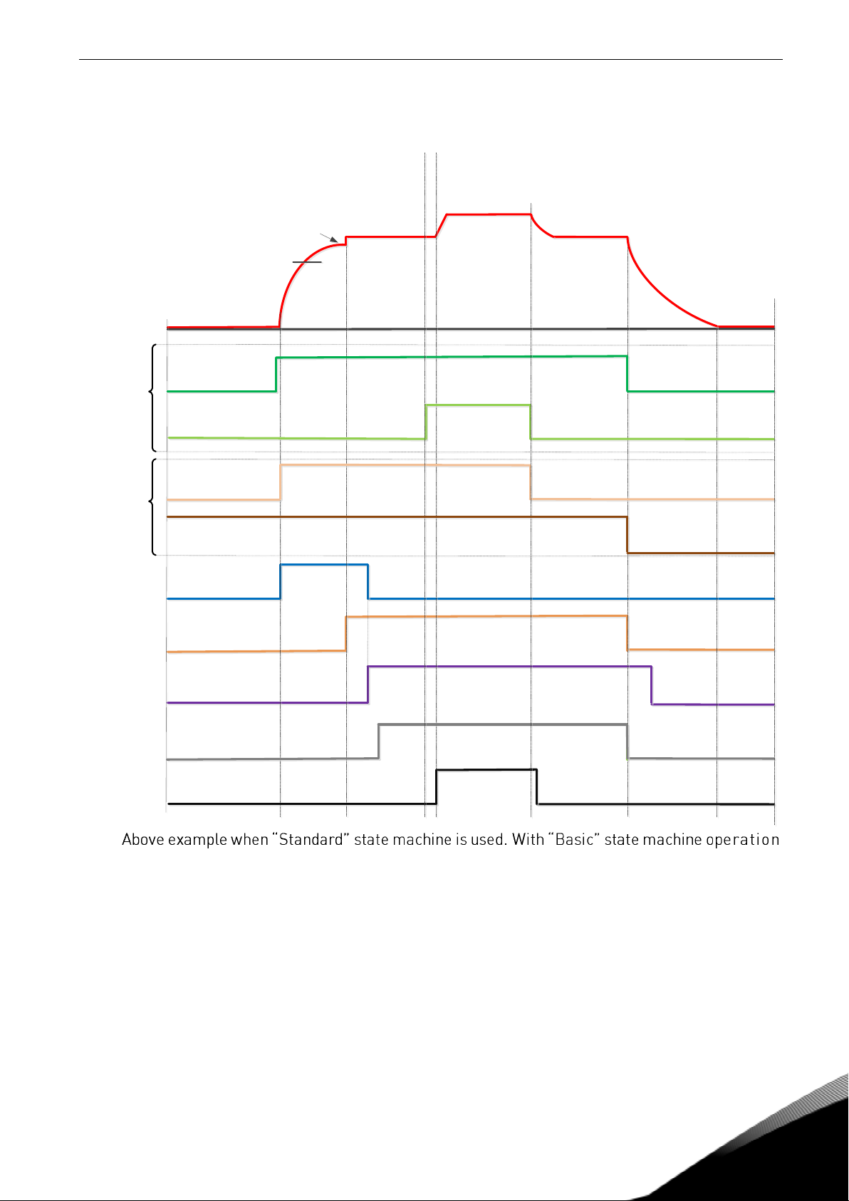
3.6 Start Stop timing diagram
DC Voltage
Charge Control
MCB Feedback
MCB Close Control
MCB Close level
Stable DC
Ready
IO Start
Run
FB CW.B00
Control in
FB Control
FB CW.B03
Contro in
IO Control
P. Start Delay
IO MCB Open
Command
is like in IO Control.
Page 16
16 • Vacon arfiff05 Standard AFE-II
Local contacts: http://drives.danfoss.com/danfoss-drives/local-contacts/
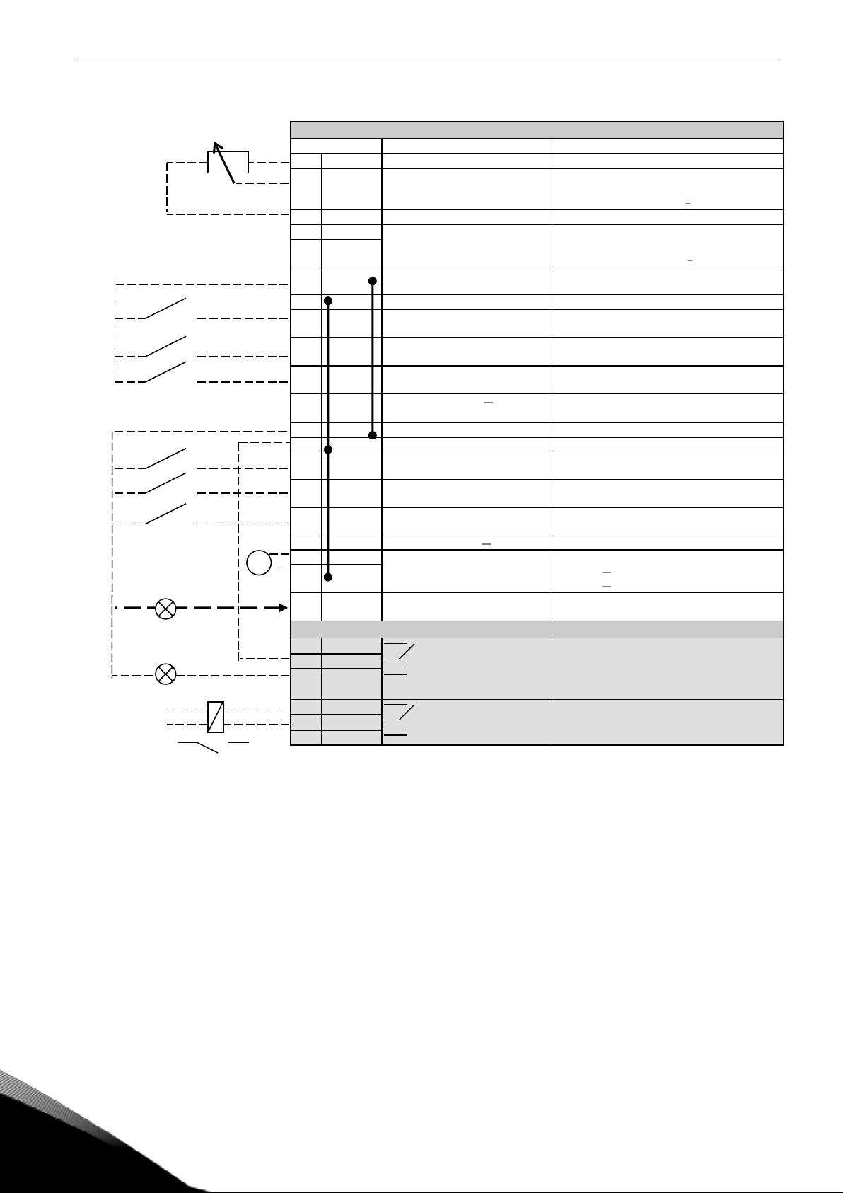
4. CONTROL IO
NXOPTA1
Terminal
Signal
Description
1
+10Vref
Reference voltage output
Voltage for potentiometer, etc.
2
AI1+
Analogue input 1.
Range 0-10V, Ri = 200
Range 0-20 mA Ri = 250
Analogue input 1
Input range selected by jumpers.
Default range: Voltage 0 10 V
3
AI1-
I/O Ground
Ground for reference and controls
4
AI2+
Analogue input 2.
Range 0-10V, Ri = 200
Range 0-20 mA Ri = 250
Analogue input 2
Input range selected by jumpers.
Default range: Current 0 20 mA
5
AI2-
6
+24V
Control voltage output
Voltage for switches, etc. max 0.1 A
7
GND
I/O ground
Ground for reference and controls
8
DIN1
Start Request
Programmable G2.3.1
Contact closed = Start Request
9
DIN2
Programmable G2.3.1
No function defined at default
10
DIN3
Fault Reset
Programmable G2.3.1
Contact closed = Fault Reset
11
CMA
Common for DIN 1 DIN 3
Connect to GND or +24V
12
+24V
Control voltage output
Voltage for switches (see #6)
13
GND
I/O ground
Ground for reference and controls
14
DIN4
MCB feedback
Contact open = MCB open
Contact closed = MCB Closed
15
DIN5
Programmable G2.3.1
No function defined at default
16
DIN6
Programmable G2.2.1
17
CMB
Common for DIN4 DIN6
Connect to GND or +24V
18
AOA1+
Analogue output 1
Programmable P2.3.1.2
Output range selected by jumpers.
Range 0 20 mA. RL, max. 500
Range 0 10 V. RL > 1k
19
AOA1-
20
DOA1
Digital output
Ready / Warning (Blinking)
Programmable
Open collector, I50mA, U48 VDC
NXOPTA2
21
RO1
Relay output 1
Programmable G2.4.1
Switching capacity
24 VCD / 8 A
250 VAC / 8 A
125 VDC / 0.4 A
22
RO1
23
RO1
24
RO2
Relay output 2
MCB Contl
Cannot be reprogrammed
Fixed to MCB control.
Closes when DC at 85 % of nominal DC.
Opens when DC below 75 % of nominal DC
25
RO2
26
RO2
Table 5-2. Default I/O configuration.
220
VAC
mA
K1
Q1
Page 17

Arfiff05 Standard AFE-II vacon • 17
Local contacts: http://drives.danfoss.com/danfoss-drives/local-contacts/
5. AFE APPLICATION MONITORING VALUES
On the next pages you will find the lists of parameters within the respective parameter groups.
Column explanations:
Code = Location indication on the keypad; Shows the operator the present parameter
number
Parameter = Name of parameter
Min = Minimum value of parameter
Max = Maximum value of parameter
Unit = Unit of parameter value; Given if available
Default = Value preset by factory
Cust =
ID = ID number of the parameter
_____ = On parameter code: Parameter value can only be changed after the Drive has been
stopped.
_____ = Monitoring value is possible to control from fieldbus by ID number
The manual presents signals that are not normally visible for monitoring. i.e. is not a parameter or
standard monitoring signal. These signals are presented with [Letter]. e.g.
[FW]MotorRegulatorStatus
[V] Normal monitoring signal
[P] Normal parameter in application.
[FW] Firmware signal, Can be monitored with NCDrive when signal type is selected Firmware
[A] Application signal, can be monitored with NCDrive when signal type is selected Application.
[R] Reference type parameter on keypad.
[F] Function. Signal is received as a output of function.
[DI] Digital input signal.
CB Circuit Breaker
MCB Main Circuit Breaker = AFE controller Circuit Breaker
Page 18
18 • Vacon arfiff05 Standard AFE-II
Local contacts: http://drives.danfoss.com/danfoss-drives/local-contacts/
5.1 Monitoring values
The monitoring values are the actual values of parameters and signals as well as statuses and
measurements. Monitoring values cannot be edited.
5.1.1 Monitoring 1
Code
Signal
Unit
ID
Description
V1.1.1
DC-Link Voltage
Vdc
1108
Measured DC Link voltage in Volts, filtered.
V1.1.2
DC-Link Ref.
Vdc
25
DC Voltage Reference in Vdc
V1.1.3
DC Voltage Ref.
%
1200
Used DC Voltage Reference
V1.1.4
DC Voltage Act.
%
7
Actual DC Voltage
V1.1.5
Total Current
A
3
Total current of the regenerative unit in
Amperes.
V1.1.6
Active Current
%
1125
Avtive current of the regenerative drive in % of
Rated Line Current.
> 0 power from AC side to DC side
< 0 power from DC side to AC side
V1.1.7
Reactive Current
%
1157
Reactive current of the regenerative drive in % of
Rated Line Current.
> 0 Inductive current
< 0 Capacitive current
V1.1.8
Supply Frequency
Hz
1
Supply frequency in ##.## Hz .The sign indicates
the phase order.
V1.1.9
Supply Voltage
V
6
Input AC voltage, RMS line to line Volts.
V1.1.10
Unit Temperature
°C
8
Heat sing temperature
V1.1.11
Status Word
43
V1.1.12
DIN 645. 321
15 V1.1.13
Analogue Input 1
%
13 V1.1.14
Analogue Input 2
%
14 V1.1.15
Analogue Out 1
%
26 V1.1.16
Operation Hours
h
1856
5.1.2 FieldBus Monitoring values
Code
Signal
Unit
ID
Description
V1.2.1
FB Control Word
1160
Control word from fieldbus
V1.2.2
FB Status Word
68
Status word to fieldbus
V1.2.3
Fault Word 1
1172
V1.2.4
Fault Word 2
1173 V1.2.5
DIN Status Word 1
56 V1.2.6
DIN Status Word 2
57 V1.2.7
Warning Word 1
1174
V1.2.8
DC Voltage
44
Unfiltered DC-Link voltage
V1.2.9
Current
1113
Unfiltered total current
V1.2.10
Drive Power
kW
1508
Electrical AFE terminal power
V1.2.11
Fault History
37 V1.2.12
Final DC Ref
%
1131
V1.2.13
Cabin State Word
1884
5.1.3 Line Monitor OPT-D7
Code
Signal
Unit
ID
Description
V1.3.1
Line Voltage
V
1650 V1.3.2
Line Frequency
Hz
1654 V1.3.3
Synch Error D7
1659 V1.3.4
Line Voltage THD
1670 V1.3.5
Line Voltage HF rms
1671
Page 19
Arfiff05 Standard AFE-II vacon • 19
Local contacts: http://drives.danfoss.com/danfoss-drives/local-contacts/
5.1.4 Master Follower
Code
Parameter
Unit
Form.
ID
Description
V1.4.1
SB SystemStatus
1601 V1.42
Master CW
93
5.1.5 Monitoring values 2
Code
Signal
Unit
ID
Description
V1.5.1
Measured temperature 1
Cº
50
4 s filtering.
V1.5.2
Measured temperature 2
Cº
51
4 s filtering.
V1.5.3
Measured temperature 3
Cº
52
4 s filtering.
V1.5.4
Measured temperature 4
Cº
69
4 s filtering.
V1.5.5
Measured temperature 5
Cº
70
4 s filtering.
V1.5.6
Measured temperature 6
Cº
71
4 s filtering.
V.1.5.7
PT-100 Temperature
Cº
42
Highest temperature of OPTB8/OPTBH board. 4 s
filtering.
5.2
Monitoring Values description
5.2.1 Monitoring 1 values
V1.1.1 DC-Link Voltage Vdc ID44
Measured DC voltage, filtered.
V1.1.2 DC-Link Ref. Vdc ID25
DC-Link voltage reference in Vdc.
V1.1.3 DC Voltage Ref. % ID1200
Used DC Voltage reference in %
V1.1.4 DC Voltage Act. % ID7
Actual DC Voltage in %
V1.1.5 Total Current A ID3
Total current of the regenerative unit in Amperes, filtered
V1.1.6 Active Current % ID1125
Active current in % of System Rated Current.
Negative value means that current is flowing to AC side from DC side i.e. regenerating.
V1.1.7 Reactive Current % ID1157
Reactive current of the regenerative drive in % of System Rated Current.
Positive is Inductive current.
Negative is capacitive current.
V1.1.8 Supply Frequency Hz ID1
Supply frequency in ##.## Hz .The sign indicates the phase order. Updated when drive in
run state. Updated also in stop state when OPT-D7 is used or Regen Options B9 is
activated.
Page 20
20 • Vacon arfiff05 Standard AFE-II
Local contacts: http://drives.danfoss.com/danfoss-drives/local-contacts/
V1.1.9 Supply Voltage V ID6
Input AC voltage, RMS line to line Volts. Updated when drive in run state.
Updates also when OPT-D7 is used.
V1.1.10 Unit Temperature °C ID8
Temperature of the unit in degrees Celsius
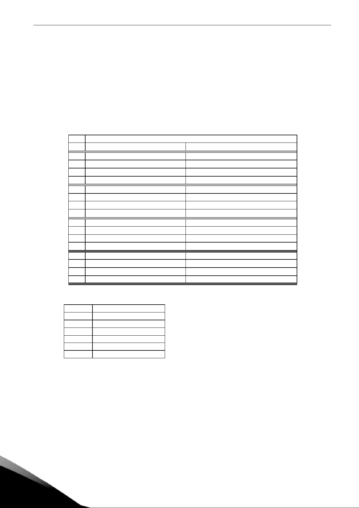
V1.1.11 Status Word ID43
Application Status Word combines different drive statuses to one data word.
Application Status Word ID43
FALSE
TRUE
b0
b1
Not in Ready state
Ready
b2
Not Running
Running
b3
No Fault
Fault
b4
b5
Quick Stop Active
Quick Stop Not Active
b6
Run Disabled
Run Enable
b7
No Warning
Warning
b8 Charging Switch closed (internal)
b9 MCB Control (DO Final)
b10 MCB Feedback
b11 DO Charging Active
b12
No Run Request
Run Request
b13
b14
b15
V1.1.12 DIN 645. 321 ID15
DIN1/DIN2/DIN3 status
B0
DIN1
B1
DIN2
B2
DIN3
B3
DIN4
B4
DIN5
B5
DIN6
V1.1.13 Analogue Input 1 % ID13
V1.1.14 Analogue Input 2 % ID14
Unfiltered analogue input level.
0 % = 0 mA / 0 V, -100 % = -10 V, 100 % = 20 mA / 10 V.
Monitoring scaling is determined by the option board parameter.
V1.1.15 Analogue Out 1 % ID26
Analogue Output value 0 % = 0 mA / 0 V, 100 % = 20 mA / 10 V
Page 21

Arfiff05 Standard AFE-II vacon • 21
Local contacts: http://drives.danfoss.com/danfoss-drives/local-contacts/
V1.1.16 Operation Hours ID1856
Run state hours
5.2.2 Fieldbus monitoring values
V1.2.1 FB Control Word ID 1160
Control word from fieldbus. Below table is for bypass operation for such fieldbus board that natively
supports this or can be parameterized to bypass mode.
FB Control Word ID1160
Signal
Comment
SM
B00
DC Charge
0= Open MCB.
1= Close DC charge contactor, MCB closed automatically, see
B01.
1,2,3
B01
MCB Close Enable
0= Disable Closing of MCB (Also opens if Control
Options.B0=TRUE)
1= Enable Closing of MCB (Works also for reclosing)
3
B02
Quick Stop
0= Quick Stop
1= No Quick Stop
3
B03
Run
0= AFE is stopped
1= AFE is started
1,2,3
B04
Output Power Limit to
Zero
0= Output Power Limit to Zero (7%)
1= Output Power Limit = P2.5.2.1
3
B05
Disable Power Increase.
Input or Output
0= Disable increase of power.
1= Power limits defined by G2.5.2
3
B06
Input Power Limit to
Zero
0= Input Power Limit to Zero (7%)
1= Output Power Limit = P2.5.2.2
3
B07
Reset
0>1 Reset fault.
1,2,3
B08
DC Voltage Ref B00
B00 | B01
0 | 0 = FB Reference. P2.2.1, if not FB Control & FB Ref > 50,00 %
0 | 1 = 110 %
1 | 0 = 115 %
1 | 1 = 120 %
2,3
B09
DC Voltage Ref B01
2,3
B10
Fieldbus Control
0= No control from fieldbus
1=Control from fieldbus
2,3
B11
Watchdog
communication between fieldbus master and the drive.
2,3
B12
FB DIN2
Can be used to control RO or directly parameter by ID number.
G2.4.1
1,2,3
B13
FB DIN3
Can be used to control RO or directly parameter by ID number.
G2.4.1
1,2,3
B14
FB DIN4
Can be used to control RO or directly parameter by ID number.
G2.4.1
1,2,3
B15
Reserved for future use.
Page 22

22 • Vacon arfiff05 Standard AFE-II
Local contacts: http://drives.danfoss.com/danfoss-drives/local-contacts/
V1.2.2 FB Status Word ID 68
FB Status word to fieldbus. Below table is for bypass operation for such fieldbus board that natively
supports this or can be parameterized to bypass mode.
FB Status Word ID68
Signal
Comment
b0
Ready On
0=Drive not ready to switch on
1=Drive ready to start charging
b1
Ready Run
0=Drive not ready to run
1=Drive ready and MCB is ON
b2
Running
0=Drive not running
1=Drive in Run state (Modulating)
b3
Fault
0=No active fault
1=Fault is active
b4
Run Enable Status
0= Run Disabled. Drive in stop state
1= Run Enabled. Drive can be started.
b5
Quick Stop Active
0=Quick Stop Active
1=Quick Stop not Active
b6
MCB Control NOT OK
0= MCB Control OK
1= MCB Requested open but DC stays high
b7
Warning
0= No active warnings
1= Warning active
b8
At Reference
0= DC Voltage Ref and Act DC Voltage are not
same.
b9
Fieldbus Control Active
0=Fieldbus control not active
1=Fieldbus control active
b10
Above Limit
0= DC Voltage is below P2.5.5.1 level
1=The DC Voltage is above the P2.5.5.1 level
b11
MCB Control (DO Final)
0= Drive is controlling MCB to be Open.
1= Drive is controlling MCB to be Closed
b12
MCB Feedback
0= Feedback indicates MCB to be Open
1= Feedback indicates MCB to be Closed
b13
Reserved for future use.
b14
DC Charge DO Control
0= DC not charged
1= DC Charging Active
b15
Watchdog
Same as received on bit 11 of the FB Control
Word.
Page 23
Arfiff05 Standard AFE-II vacon • 23
Local contacts: http://drives.danfoss.com/danfoss-drives/local-contacts/
V1.2.3 Fault Word 1 ID 1172
Fault Word 1 ID1172
Fault
Fault Codes
b0
Over Current
F1
b1
Overvoltage
F2
b2
Under voltage
F9
b3
Not used
b4
Earth Fault
F3
b5
Not used
b6
Unit Over Temperature
F14
b7
Over Temperature
F59, F56,F71
b8
Input Phase loss
F11
b9
Not used
b10
Device Fault
F37, F38, F39, F40, F44, F45
b11
Not used
b12
Not used
b13
Not used
b14
Not used
b15
Not used
V1.2.4 Fault Word 2 ID 1173
Fault Word 2 ID1173
Fault
Fault Codes
b0
Not used
b1
Charging Switch Fault
F5, F80
b2
Not used
b3
Drive Hardware fault
F4, F7
b4
Under Temperature
F13
b5
EPROM or Checksum fault
F22
b6
External fault
F51
b7
Not used
b8
Internal Communication
F25
b9
IGBT Temperature
F31, F41
b10
Not used
b11
Cooling fan
F32, F70
b12
Application fault
F35
b13
Drive Internal fault
F33, F36, F8, F26
b14
MCB State
F64
b15
Not used
Page 24
24 • Vacon arfiff05 Standard AFE-II
Local contacts: http://drives.danfoss.com/danfoss-drives/local-contacts/
V1.2.5 DIN Status 1 ID 56
V1.2.6 DIN Status 2 ID57
DIN Status Word 1
DIN Status Word 2
b0
DIN: A.1
DIN: C.5
b1
DIN: A.2
DIN: C.6
b2
DIN: A.3
DIN: D.1
b3
DIN: A.4
DIN: D.2
b4
DIN: A.5
DIN: D.3
b5
DIN: A.6
DIN: D.4
b6
DIN: B.1
DIN: D.5
b7
DIN: B.2
DIN: D.6
b8
DIN: B.3
DIN: E.1
b9
DIN: B.4
DIN: E.2
b10
DIN: B.5
DIN: E.3
b11
DIN: B.6
DIN: E.4
b12
DIN: C.1
DIN: E.5
b13
DIN: C.2
DIN: E.6
b14
DIN: C.3
b15
DIN: C.4
V1.2.7 Warning Word 1 ID 1174
Warning Word 1 ID1174
Fault
Fault Codes
b0
Not used
b1
Temperature protection
W29: Thermistor warning,
W56: FPT100 warning or
W71: LCL over temperature warning
b2
b3
Supply Phase Warning
W11
b4
Not used
b5
Not used
b6
Not used
b7
Drive over temperature
W14
b8
Not used
b9
Not used
b10
Fan Warning
W32: Fan Cooling
W70: LCL Fan monitor warning
b11
Not used
b12
Not used
b13
Not used
b14
Not used
b15
Not used
V1.2.8 DC Voltage [Vdc] ID44
Unfiltered DC-Link Voltage
Page 25
Arfiff05 Standard AFE-II vacon • 25
Local contacts: http://drives.danfoss.com/danfoss-drives/local-contacts/
V1.2.9 Current [A] ID1113
Total unfiltered current
V1.2.10 Drive Power [kW] ID 1508
Drive input terminal electrical power.
V1.2.11 Fault History ID37
Last active fault. If drive has several fault at the same time see from fault history what
was the first fault.
V1.2.12 Final DC Ref [%] ID1131
Final DC Reference, including offset control.
V1.2.13 Cabin State Word ID1884
Cabin State Word ID1884
Fault
Fault Codes
b0
Main Fuse
W81
b1
Aux voltage
W82
b2
STO Fuse
W83
b3
Insulation Fault
W84
b4
Earthswitch Fault
W85
b5
Arc Relay
W86
b6
high Amb Temp.
W88
b7
Leakage
W89
b8
Not used
b9
Not used
b10
Not used
b11
Not used
b12
Not used
b13
Not used
b14
Not used
b15
Not used
Page 26
26 • Vacon arfiff05 Standard AFE-II
Local contacts: http://drives.danfoss.com/danfoss-drives/local-contacts/
5.2.3 Line monitoring OPT-D7
V1.3.1 Line Voltage V ID1650
The measured line voltage rms value when using the OPT-D7 option board in slot C.
V1.3.2 Line Frequency Hz ID1654
The measured line voltage frequency when using the OPT-D7 option board in slot C.
V1.3.3 Synch Error D7 ID1659
An error on voltage angles between the drive and the measurement taken by OPT-D7.
-3072...+3071 = -180...180 degrees.
If the value is not near to zero when running in AFE mode, the phase order may be wrong
even if the OPT-D7 frequency is correct (Error about 2047 = 120 degree). If measurement
is after Dyn11 transformer error is usually about 512 (30,0 Degree).
V1.3.4 Line Voltage THD ID1670
V1.3.5 LineVoltageHFrms ID1671
5.2.4 Master/Follower
Here are gathered relevant signals in Master follower system.
V1.4.1 SB SystemStatus ID 1601
System Bus Status Word ID1601
FALSE
TRUE
b0 Not used
b1 Drive 1 Ready
b2 Drive 1 Running
b3 Drive 1 Fault
b4 Not used
b5 Drive 2 Ready
b6 Drive 2 Running
b7 Drive 2 Fault
b8 Not used
b9 Drive 3 Ready
b10 Drive 3 Running
b11 Drive 3 Fault
b12 Not used
b13 Drive 4 Ready
b14 Drive 4 Running
b15 Drive 4 Fault
V1.4. 2 Master CW ID93
Master Drive Control Word. Master Sending, Follower receiving.
Page 27

Arfiff05 Standard AFE-II vacon • 27
Local contacts: http://drives.danfoss.com/danfoss-drives/local-contacts/
5.2.5 Monitoring values 2
V1.5.1 Measured temperature 1 Cº ID 50
V1.5.2 Measured temperature 2 Cº ID 51
V1.5.3 Measured temperature 3 Cº ID 52
V1.5.4 Measured temperature 4 Cº ID 69
V1.5.5 Measured temperature 5 Cº ID 70
V1.5.6 Measured temperature 6 Cº ID 71
V1.5.7 PT-100 Temperature Cº ID 42
Highest temperature of OPTB8/OPTBH board. 4 s filtering.
Page 28
28 • Vacon arfiff05 Standard AFE-II
Local contacts: http://drives.danfoss.com/danfoss-drives/local-contacts/
6. PARAMETER LIST
6.1 Basic parameters
Code
Parameter
Min
Max
Unit
Default
ID
Note
P2.1.1
Grid Nominal Voltage
500V:
380V
690V:
525V
500V:
500V
690V:
690V
V
400
110
Set here the nominal voltage of
the grid.
P2.1.2
Grid Nominal
Frequency
48
63
Hz
50
1532
Set here the nominal
frequency of the grid.
P2.1.3
System Rated Current
0,0
Ih A Ih
113
Capacity of supply, used if
oversized AFE.
P2.1.4
System Rated Power
0
32000
kW 0 116
P2.1.5
Parallel AFE
0 3 0 1501
0 = Single AFE
1 = Parallel AFE
1 = Master
1 = Follower
Table 5-2. Basic parameters
6.2 Reference Handling
Code
Parameter
Min
Max
Unit
Default
ID
Note
P2.2.1
DC Voltage Ref.
105
Varies
%
110,00
1462
DC Voltage reference as % of
Nominal DC Voltage
Nominal DC voltage = 1,35 *
Supply voltage
P 2.2.2
DC Voltage Drooping
0,00
100,00 0,00
620
AFE drooping DC-voltage. Set
to 3,00 % when parallel AFE
operation is selected
P2.2.3
Reactive Current
Reference
-100,0
100,0 % 0,0
1459
Regenerative reactive current
reference 100,0 = nominal
current.
Positive =Inductive
Negative = Capacitive
P2.2.4
DC Reference Offset
-5,00
5,00 % 0,00
1777
Table 1- 1, Reference Handling
Page 29
Arfiff05 Standard AFE-II vacon • 29
Local contacts: http://drives.danfoss.com/danfoss-drives/local-contacts/
6.3 Input signals
6.3.1 Digital inputs
Code
Parameter
Min
Max
Unit
Default
ID
Description
P2.3.1.1
Start Signal 1
0.1
E.10
DigIn:
A.1
403
P2.3.1.2
Enable MCB Close
0.1
E.10
DigIn:
0.2
1619
With CO.B00; Opens MCB
also
P2.3.1.3
Open MCB Power
Dawn
0.1
E.10
DigIn:
0.2
1600
Power down command
P2.3.1.4
LCL Temp. X51
0.1
E.10
DigIn:
0.2
1179
P2.3.1.5
LCL Temp. X52
0.1
E.10
DigIn:
0.2
1125
P2.3.1.6
MCB Status
0.1
E.10
DigIn:
A.4
1453
P2.3.1.7
Run Enable
0.1
E.10
DigIn:
0.2
407
P2.3.1.8
Quick Stop
0.1
E.10
DigIn:
0.2
1213
Power down with a
warning
P2.3.1.9
Ext. Fault 1
0.1
E.10
DigIn:
0.1
405
P2.3.1.10
Ext. Fault 2
0.1
E.10
DigIn:
0.1
406
P2.3.1.11
Fault Reset
0.1
E.10
DigIn:
0.1
414
P2.3.1.12
LC Cooling
0.1
E.10
DigIn:
0.2
750
P2.3.1.13
MCB Trip State
0.1
E.10
DigIn
0.1
1706
Table 5-3. Digital inputs parameters
6.3.2 Analogue Input 1
Code
Parameter
Min
Max
Unit
Default
ID
Note
P2.4.3.1
AI1 signal selection
0.1
E.10
AnIN:
0.1
377
P2.4.3.2
AI1 filter time
0,000
32,000 s 0,000
324
P2.4.3.3
AI1 custom
minimum setting
-160,00
160,00 % 0,00
321
P2.4.3.4
AI1 custom
maximum setting
-160,00
160,00 % 100,00
322
P2.4.3.5
AI1 signal inversion
0 1 0 387
P2.4.3.6
AI1 reference
scaling, minimum
value
-32000
32000 0
303
P2.4.3.7
AI1 reference
scaling, maximum
value
-32000
32000 0
304
P2.4.3.8
AI1 Controlled ID
0
10000 0
1507
Table 1- 2, ANALOG INPUT1,
6.3.3 Analogue Input 2
Code
Parameter
Min
Max
Unit
Default
ID
Note
P2.4.4.1
AI2 signal selection
0.1
E.10
AnIN:
0.1
388
P2.4.4.2
AI2 filter time
0,000
32,000 s 0,000
329
P2.4.4.3
AI2 custom
minimum setting
-160,00
160,00 % 0,00
326
P2.4.4.4
AI2 custom
maximum setting
-160,00
160,00 % 100,00
327
P2.4.4.5
AI2 signal inversion
0 1 0 398
P2.4.4.6
AI2 reference
scaling, minimum
value
-32000
32000 0
393
P2.4.3.7
AI2 reference
scaling, maximum
value
-32000
32000 0
394
P2.4.4.8
AI2 Controlled ID
0
10000 0
1511
Table 1- 3, ANALOG INPUT2
Page 30

30 • Vacon arfiff05 Standard AFE-II
Local contacts: http://drives.danfoss.com/danfoss-drives/local-contacts/
6.3.4 Cabin State DI
Code
Parameter
Min
Max
Unit
Default
ID
Description
P2.3.4.1
Main Fuse
0.1
E.10
DigIn:
0.2
1700
P2.3.4.2
Aux Voltage
0.1
E.10
DigIn:
0.2
1703
P2.3.4.3
STO Fuse
0.1
E.10
DigIn:
0.2
1702
P2.3.4.4
Insulation Fault
0.1
E.10
DigIn:
0.2
1704
P2.3.4.5
Earthswitch Fault
0.1
E.10
DigIn:
0.2
1732
P2.3.4.6
Arc Relay
0.1
E.10
DigIn:
0.2
1733
P2.3.4.7
High Amb Temp.
0.1
E.10
DigIn:
0.2
1734
P2.3.4.8
Leakage
0.1
E.10
DigIn:
0.2
1735
6.3.5 Options
Code
Parameter
Min
Max
Unit
Default
ID
Note
P2.3.5.1
Start/Stop Logic
0 2 0 300
0/Static
1/ Rising edge
2/ Pulse
P2.3.5.2
Input Inversion
0
65535 0
1091
Table 1- 4, Digital input options
Page 31

Arfiff05 Standard AFE-II vacon • 31
Local contacts: http://drives.danfoss.com/danfoss-drives/local-contacts/
6.4 Output signals
6.4.1 Digital Outputs
Code
Parameter
Min
Max
Unit
Default
ID
Description
P2.4.1.1
MCB Control (Close)
B.2
B.2
DigOUT:
B.2
1218
Static if ID1219 < DigOUT:A.1
P2.4.1.2
MCB Control Open
0.1
E.10
DigOUT:
0.1
1219
Pulse, if used also ID1218 is
pulse control.
P2.4.1.3
Ready
0.1
E.10
DigOUT:
0.1
432
P2.4.1.4
Run
0.1
E.10
DigOUT:
0.1
433
P2.4.1.5
Fault
0.1
E.10
DigOUT:
0.1
434
P2.4.1.6
Fault,Inverted
0.1
E.10
DigOUT:
0.1
435
P2.4.1.7
Warning
0.1
E.10
DigOUT:
0.1
436
P2.4.1.8
DC Above Limit
0.1
E.10
DigOUT:
0.1
451
P2.4.1.9
DC Charge
0.1
E.10
DigOUT:
0.1
1668
P2.4.1.10
Ready To Start
0.1
E.10
DigOUT:
0.1
1686
P2.4.1.11
FB Dig Input 1
0.1
E.10
DigOUT:
0.1
455
P2.4.1.12
FB Dig 1 Input Par
0
10000
ID 0 891
P2.4.1.13
FB Dig Input 2
0.1
E.10
DigOUT:
0.1
456
P2.4.1.14
FB Dig 2 Input Par
0
10000
ID 0 892
P2.4.1.15
FB Dig Input 3
0.1
E.10
DigOUT:
0.1
457
P2.4.1.16
FB Dig 3 Input Par
0
10000
ID 0 893
P2.4.1.17
FB Dig Input 4
0.1
E.10
DigOUT:
0.1
169
P2.4.1.18
FB Dig 4 Input Par
0
10000
ID 0 894
P2.4.1.19
FB Dig Input 5
0.1
E.10
DigOUT:
0.1
170
P2.4.1.20
FB Dig 5 Input Par
0
10000
ID 0 895
Table 5-4. Digital outputs parameters
6.4.2 ANALOG OUTPUT 1
Code
Parameter
Min
Max
Unit
Default
ID
Note
P2.4.2.1
Iout 1 signal
0.1
E.10
AnOUT
A.1
464
P2.4.2.2
Iout Content
0 4 307
0 = 4 mA
1 = DC-Link Voltage
2 = Current
3 = Power
4 = +- Power
P2.4.2.3
Iout Filter
Time
0
10 s 1
308
0=No filtering
P2.4.2.4
Iout Invert
0 1 0 309
0=Not inverted
1=Inverted
P2.4.2.5
Iout Minimum
0 1 0 310
0=0 mA
1=4 mA
P2.4.2.6
Iout Scale
10
1000 % 100
311
Percentage multiplier.
Defines output when
content is it maximum value
P2.4.2.7
Iout Offset
-100
100 % 0
375
Add -1000 to 1000% to the
analogue output.
Table 1- 5, Output signals, G2.3.4
Page 32

32 • Vacon arfiff05 Standard AFE-II
Local contacts: http://drives.danfoss.com/danfoss-drives/local-contacts/
6.4.3 Options
Code
Parameter
Min
Max
Unit
Default
ID
Note
P2.4.3.1
Output
Inversion
0 1
0
1806
P2.4.3.2
MCB Close
Mode
0 2
0
1607
0 = DC Voltage
1 = DC or Start command
2 = Start Command.
Page 33

Arfiff05 Standard AFE-II vacon • 33
Local contacts: http://drives.danfoss.com/danfoss-drives/local-contacts/
6.5 Limit Settings
6.5.1 Current Limit
Code
Parameter
Min
Max
Unit
Default
ID
Note
P2.5.1.1
Current Limit
0
Varies A Varies
107
Total current limit
P2.5.1.2
Output Active
Current Limit
0
300,0 % 150,0
1290
Generating Active Current
limit in AFE mode to grid.
P2.5.1.3
Input Active Current
Limit
0
300,0 % 150,0
1289
Motoring active current limit
in AFE mode to DC-link.
6.5.2 Power Limit
Code
Parameter
Min
Max
Unit
Default
ID
Note
P 2.5.2.1
Output Power Lim
0
300,0 % 150,0
1288
Generating power limit
P 2.5.2.2
Input Power Lim
0
300,0 % 150,0
1287
Motoring power limit
6.5.3 Frequency Limit
Code
Parameter
Min
Max
Unit
Default
ID
Note
P 2.5.3.1
Low Frequency Trip
Limit
42
120 % 80
1717
P 2.5.3.2
High Frequency Trip
Limit
42
120 % 120
1716
6.5.4 AC Voltage Limit
Code
Parameter
Min
Max
Unit
Default
ID
Note
P 2.5.4.1
Low AC Voltage Trip
Limit
50
150 % 80
1711
P 2.5.4.2
High AC Voltage Trip
Limit
50
150 % 120
1710
6.5.5 DC Voltage Limit
Code
Parameter
Min
Max
Unit
Default
ID
Note
P2.5.5.1
DC Super Vision
Limit
0
1300
Vdc
600
1454
P2.5.5.2
High MCB Close
Limit
0
1300
Vdc 0 1251
Page 34

34 • Vacon arfiff05 Standard AFE-II
Local contacts: http://drives.danfoss.com/danfoss-drives/local-contacts/
6.6 Drive Control parameters
Code
Parameter
Min
Max
Unit
Default
ID
Description
P2.6.1
AFE Options 1
0
65535
544
1463 P2.6.2
AFE Options 2
0
65535 0
1464
P2.6.3
Control Options
0
65536 0
1707
Control word for activating
special features.
P2.6.4
Start Delay
0,00
320,00
s
0,50
1500
Starting delay when run
command is given. When
programming different
delay to paralleled units,
the units will start in
sequence.
P2.6.5
Modulator Type
0 4
Single:
2
Parallel
1
1516
0 = Hardware
1 = Software 1
2 = Software 2
3 = Software 3
4 = Software 4
P2.6.6
Operation Time
0
2^32
1855
Table 5-6. Drive control parameters G2.4
6.6.1 Control
Code
Parameter
Min
Max
Unit
Default
ID
Description
P2.6.7.1
Capacitor Size
0
100 % 6,3
1460 P2.6.7.2
Inductor Size
0
100 % 15,5
1461 P2.6.7.3
Dynamic Support Kp
0
32000 0
1797 P2.6.7.4
Synch Kp
0
32000
2000
1457 P2.6.7.5
Synch Ti
0
1000 50
1458 P2.6.7.6
Active Current Kp
0
4000 400
1455 P2.6.7.7
Active Current Ti
0,0
100,0 1,5
1456 P2.6.7.8
Synch. Kp Start
0
10000
4000
1300 P2.6.7.9
Voltage Ctrl Kp
0
32000
200
1451
P2.6.7.10
Voltage Ctrl Ti
0
1000
ms
50
1452
P2.6.7.11
Switching Frequency
3,4
Varies
Hz
3,6
601
Table 5-6. Drive control parameters G2.4
Page 35

Arfiff05 Standard AFE-II vacon • 35
Local contacts: http://drives.danfoss.com/danfoss-drives/local-contacts/
6.7 Protections
6.7.1 General
Code
Parameter
Min
Max
Unit
Default
ID
Description
2.7.1.1
Response to
Thermistor fault
0 3 2 732
0=No response
1=Warning
2=Fault
3=Fault, DC OFF
2.7.1.2
Input Filter Over
Temperature
Response
0 3 2 1505
0=No response
1=Warning
2=Fault
3=Fault, DC OFF
2.7.1.3
External Fault
Response
0 3 2 701
0=No response
1=Warning
2=Fault
3=Fault, DC OFF
2.7.1.4
MCB At Fault
0 1 0 1699
2.7.1.5
Charge Max Time
0,00
60,00
s
10,00
1522
Charging time limit when
drive charging options are
used.
Table 5-9. General Protections parameters G2.7.1
6.7.2 Temperature sensor protections
Code
Parameter
Min
Max
Unit
Default
Cust
ID
Note
P2.7.2.1
No. of used inputs
on board 1
0 5
0 739
0=Not used (ID Write)
1 = Sensor 1 in use
2 = Sensor 1 & 2 in use
3 = Sensor 1 & 2 & 3 in use
4 = Sensor 2 & 3 in use
5 = Sensor 3 in use
P2.7.2.2
Response to
temperature fault
0 3
2 740
0=No response
1=Warning
2=Fault,stop acc. to 2.3.2
3=Fault,stop by coasting
P2.7.2.3
Board 1 warning
limit
30,0
200,0
Cº
120,0
741
P2.7.2.4
Board 1 fault limit
30,0
200,0
Cº
130,0
742
P2.7.2.5
No. of uses inputs
on board 2
0 5
0 743
0=Not used (ID Write)
1 = Sensor 1 in use
2 = Sensor 1 & 2 in use
3 = Sensor 1 & 2 & 3 in use
4 = Sensor 2 & 3 in use
5 = Sensor 3 in use
P2.7.2.6
Response to
temperature fault
0 3
2 766
0=No response
1=Warning
2=Fault,stop acc. to 2.3.2
3=Fault,stop by coasting
P2.7.2.7
Board 2 warning
limit
30,0
200,0
Cº
120,0
745
P2.7.2.8
Board 2 fault limit
30,0
200,0
Cº
130,0
746 P2.7.2.9.1
Channel 1B Warn
-30,0
200,0
Cº
0,0
764 P2.7.2.9.2
Channel 1B Fault
-30,0
200,0
Cº
0,0
765 P2.7.2.9.3
Channel 1C Warn
-30,0
200,0
Cº
0,0
768 P2.7.2.9.4
Channel 1C Fault
-30,0
200,0
Cº
0,0
769 P2.7.2.9.5
Channel 2B Warn
-30,0
200,0
Cº
0,0
770 P2.7.2.9.6
Channel 2B Fault
-30,0
200,0
Cº
0,0
771
P2.7.2.9.7
Channel 2C Warn
-30,0
200,0
Cº
0,0
772
P2.7.2.9.8
Channel 2C Fault
-30,0
200,0
Cº
0,0
773
Page 36

36 • Vacon arfiff05 Standard AFE-II
Local contacts: http://drives.danfoss.com/danfoss-drives/local-contacts/
6.7.3 Fieldbus
Code
Parameter
Min
Max
Unit
Default
ID
Description
2.7.3.1
FB Fault Response
0 2 2 733
0=No response
1=Warning
2=Fault
2.7.3.2
FB WD Delay
0,00
30,00 0,00
1354
0,00 = Disabled WD
Table 5-9. Fieldbus Protections parameters G2.7.2
6.7.4 OPT-D7 protections
Code
Parameter
Min
Max
Unit
Default
ID
Description
2.7.4.1
THD Response
0 2 0 1672
2.7.4.2
THD Warn. Limit
0,00
50,00 % 6,00
1673
2.7.4.3
THD Fault Limit
0,00
50,00
%
10,00
1674
2.7.4.4
HF rms Response
0 2 0 1675
2.7.4.5
HF rms Warn Limit
0,0
400,0 V 20,0
1676
2.7.4.6
HF rms Fault Limit
0
400,0 V 60,0
1677
Table 5-9. OPT-D7 Protection parameters G2.7.3
6.7.5 Options
Code
Parameter
Min
Max
Unit
Default
ID
Description
2.7.5
Fault Simulation
0
65535 0
1569
2.7.6
Reset Datalogger
0 1 0 1857
Resets datalogger to
defaults.
Table 5-9. Options parameters G2.7.2
Page 37

Arfiff05 Standard AFE-II vacon • 37
Local contacts: http://drives.danfoss.com/danfoss-drives/local-contacts/
6.8 Fieldbus parameters
Code
Parameter
Min
Max
Unit
Default
ID
Description
P2.8.1
FB Actual Value
Selection
0
65535
ID 7 1853
P2.8.2
Fieldbus data out 1
selection
0
65535
ID 0 852
Choose monitoring data
with parameter ID
P2.8.3
Fieldbus data out 2
selection
0
65535
ID 0 853
P2.8.4
Fieldbus data out 3
selection
0
65535
ID 0 854
P2.8.5
Fieldbus data out 4
selection
0
65535
ID 0 855
P2.8.6
Fieldbus data out 5
selection
0
65535
ID 0 856
P2.8.7
Fieldbus data out 6
selection
0
65535
ID 0 857 P2.8.8
Fieldbus data out 7
selection
0
65535
ID 0 858
P2.8.9
Fieldbus data out 8
selection
0
65535
ID 0 859
P2.8.10
Fieldbus data in 1
selection
0
65535
ID 0 876
Choose controlled data
with parameter ID
P2.8.11
Fieldbus data in 2
selection
0
65535
ID 0 877
P2.8.12
Fieldbus data in 3
selection
0
65535
ID 0 878
P2.8.13
Fieldbus data in 4
selection
0
65535
ID 0 879
P2.8.14
Fieldbus data in 5
selection
0
65535
ID 0 880
P2.8.15
Fieldbus data in 6
selection
0
65535
ID 0 881
P2.8.16
Fieldbus data in 7
selection
0
65535
ID 0 882
P2.8.17
Fieldbus data in 8
selection
0
65535
ID 0 883
P2.8.18
GSW ID
0
65535
ID
68
897
P2.8.19
State Machine
0 3 1 896
Table 5-8. Fieldbus parameters G2.6
Page 38

38 • Vacon arfiff05 Standard AFE-II
Local contacts: http://drives.danfoss.com/danfoss-drives/local-contacts/
6.9 ID Control Functions
6.9.1 Value control
Table 1. Power reference input signal selection, G2.2.8
Code
Parameter
Min
Max
Unit
Default
Cust
ID
Description
P2.9.1.1
Control Input Signal
ID
0
10000
ID
0
1580
P2.9.1.2
Control Input Off
Limit
-32000
32000 0
1581
P2.9.1.3
Control Input On
Limit
-32000
32000 0
1582
P2.9.1.4
Control Output Off
Value
-32000
32000 0
1583
P2.9.1.5
Control Output On
Value
-32000
32000 0
1584
P2.9.1.6
ID
0
10000
ID
0
1585
P2.9.1.7
Control Mode
0 5
0
1586
0 = SR ABS
1 = Scale ABS
2 = Scale INV ABS
3 = SR
4 = Scale
5 = Scale INV
P2.9.1.8
Control Output
Filtering rime
0.000
32.000 s 0.000
1721
6.9.2 DIN ID Control 1
Table 2. DIN ID control parameters, G2.2.8
Code
Parameter
Min
Max
Unit
Default
Cust
ID
Description
P2.9.2.1
ID Control DIN
0.1
E.10
0.1
1570
Slot Board input No.
If 0.1 ID61 can be
controlled from FB
P2.9.2.2
Controlled ID
0
10000
ID
0 1571
Select ID that is
controlled by digital input
P2.9.2.3
False value
-32000
32000 0 1572
Value when DI is low
P2.9.2.4
True value
-32000
32000 0 1573
Value when DI is high
Page 39

Arfiff05 Standard AFE-II vacon • 39
Local contacts: http://drives.danfoss.com/danfoss-drives/local-contacts/
6.10 Keypad control (Control keypad: Menu M3)
Code
Parameter
Default
Min
Max
Unit
ID
Description
P3.1
Control place
2 0 2 125
0=Fieldbus
1=I/O terminal
2=Keypad (Default)
Table 5-11. Keypad control parameters M3
6.11 System menu (Control keypad: Menu M6)
For parameters and functions related to the general use of the frequency converter, such as
application and language selection, customised parameter sets or information about the hardware
and software, see Chapter 7.3.6 in the Vacon NX User's Manual.
6.12 Expander boards (Control keypad: Menu M7)
The M7 menu shows the expander and option boards attached to the control board and boardrelated information. For more information, see Chapter 7.3.7 in the Vacon NX User's Manual and
Vacon I/O option board manual.
Page 40

40 • Vacon arfiff05 Standard AFE-II
Local contacts: http://drives.danfoss.com/danfoss-drives/local-contacts/
7. DESCRIPTION OF PARAMETERS
7.1 Basic parameters
2.1.1 Grid Nominal Voltage [# V] ID110
This parameter sets the incoming line voltage for the regenerative drive. The maximum
value is 690 V, Set this parameter to the nominal line voltage at the installation site.
2.1.2 Grid Nominal Frequency [#,## Hz] ID1532
Grid Nominal frequency. Used for frequency protection functions and initial guess for
synchronization frequency.
2.1.3 System Rated Current [A] ID113
Rated current capacity of the supply or the transformer. May need to be set if AFE is
oversized compared to LCL or feeding transformer capacity. For testing purposes, the
feeding transformer should not be less than 20% of the unit nominal current or following
breakers or fuses. Recommended not to increase System Rated Current above IH
Current.
2.1.4 System Rated Power [kW] ID116
Set here the rated active power of the system.
2.1.5 Parallel AFE ID1501
0 = Single AFE
1 = Parallel AFE
When selecting parallel, AFE DC Drooping is set to 4,00 %, Software Modulation 1 is
activated (Default Software Modulator 2) and modulation is automatically synchronized
between AFE units in common DC bus.
2 = Master
When selecting Master, AFE DC Drooping is set to 4,00 %, Software Modulation 1 is
activated (Default Software Modulator 2) and modulation is automatically synchronized
between AFE units in common DC bus. Start Command is send trough system bus to
follower drives
3 = Follower
When selecting follower, AFE DC Drooping is set to 4,00 %, Software Modulation 1 is
activated (Default Software Modulator 2) and modulation is automatically synchronized
between AFE units in common DC bus. Follower drive revives start command from
master drive through system bus.
Page 41

Arfiff05 Standard AFE-II vacon • 41
Local contacts: http://drives.danfoss.com/danfoss-drives/local-contacts/
7.2 Reference Handling
P2.2.1 DC Voltage Reference [#,## %] ID1462
This parameter sets the DC Voltage reference in % of Nominal DC voltage (Nominal DC
voltage = 1,35 * Grid Nominal Voltage). The DC Voltage will be maintained at this level
when regenerative unit is running. Ramp rate for reference is 5 % / 100 ms.
NOTE! DC-link voltage should not exceed the following values:
• 797 Vdc for 500V unit
• 1099 Vdc for 690V unit
DC Voltage is limited to these values regardless of reference.
In fieldbus control DC Voltage Reference can be given in FBSpeedReference signal. If
FBSpeedReference is below 50,00 % keypad reference is used instead but minimum is
always limited to 105,00 %.
P2.2.2 DC Droop ID620
When AFEs are used in parallel, drooping can be used for current balancing. The DCV
voltage reference drooping is set as % of active current reference.
E.g. if drooping is 3.00% and active current is 50% then DC voltage reference is reduced
1,5%.
P2.2.3 Reactive Current Reference ID1459
This parameter sets the reference for the reactive current in % of the rated current. This
can be used for power factor correction of AFE system or reactive power compensation.
Positive value makes inductive power to the grid
Negative value makes capacitive power to the grid.
P2.2.4 DC Reference Offset
Offset for DC Reference, used to balance parallel unit active current while using same
DC Reference P2.2.1. in all units.
Page 42

42 • Vacon arfiff05 Standard AFE-II
Local contacts: http://drives.danfoss.com/danfoss-drives/local-contacts/
7.3 Input signals
7.3.1 Digital inputs
P2.3.1.1 Start Signal 1 ID403
Start signal, See Start/Stop Logic ID 300.
P2.3.1.2 Enable MCB Close ID1619
Enables MCB closing, false keeps MCB open even if required DC Voltage level has been
reached. With Control Options B00 MCB is also opened without need to discharge DC
link.
P2.3.1.3 Open MCB PowerDown ID1600
Signal FALSE status will stop the AFE unit and discharge DC.
System is powered down.
On keypad control pressing Stop button more than a 2 second will open the MCB.
P2.3.1.4 LCL Temp. X51 ID1179
This parameter defines if the drive monitors the status of the LCL Fan of the unit. If the
monitoring function is used, the unit will give a warning if the LCL fan stops working and
LCL temperature reaches warning level.
Check from hardware if LCL is using X51 for fan monitoring or for LCL Temperature
monitoring. If hardware uses X51 for fan monitoring use this parameter if it is used for
LCL temperature monitoring use P2.3.1.10 LCL Temperature Monitoring X51.
This signal is normally used in cabinet installations. If status of the LCL fan is not
monitored in the syst
P2.3.1.5 LCL Temp. X52 ID1125
This parameter defines if the drive monitors the status of the LCL over temperature
supply.
This signal is normally used in cabinet installations. If LCL Over temperature monitoring
P2.3.1.6 MCB Status ID1453
This parameter defines what input is used to monitor status of the MCB of the unit. If
feedback does not correspond the control signal within 4 second time delay drive will
indicate MCC Fault and will not be able to start until proper feedback is give. If feedback
is lost during run state fault is immediate and MCB Open command is given.
NOTE! AFE needs feedback signal for correct operation. If feedback is not used there
will be 3 second delay after closing command before drive can be started.
Page 43

Arfiff05 Standard AFE-II vacon • 43
Local contacts: http://drives.danfoss.com/danfoss-drives/local-contacts/
P2.3.1.7 Run Enable ID407
This parameter defines which digital input is used for external Run Enable signal. If Run
Enable is used the drive does not go to Ready state until the Run Enable goes high.
P2.3.1.8 Quick Stop (Power Down) ID1213
Drive is stopped and MCB is opened immediately and DC needs to go zero to make
restart. Power Down command with a warning indication (Recorded to fault history).
P2.3.1.9 Ext. Fault 1 ID405
P2.3.1.10 Ext. Fault 2 ID406
This parameter defines if the drive monitors the status of the External fault input. The
response to the fault can be selected with the parameter P2.7.2.
P2.3.1.11 Fault Reset ID414
This parameter defines which digital input is used to reset faults.
P2.3.1.12 LC Cooling ID750
OK input from the cooling unit. Warning indication if unit is not in run state or there is not
active run request. Response is fault within 3 second if unit is in run state or there is an
active run request.
P2.3.1.13 MCB Trip State ID1706
Input signal for Main Circuit Breaker trip state. Gives F64 with and subcode.
Page 44

44 • Vacon arfiff05 Standard AFE-II
Local contacts: http://drives.danfoss.com/danfoss-drives/local-contacts/
7.3.2 Analogue Inputs
2.3.2.1 AI1 signal selection ID377
2.3.2.1 AI2 signal selection ID388
Connect the AI1/AI2 signal to the analogue input of your choice with this parameter.
When analogue input selection parameter is set to 0.1 you can control analogue input
monitoring variable from Fieldbus by assign process data input ID number to monitoring
signal thus allowing making of scaling function in drive side to PLC input signals.
2.3.2.2 Analogue input 1 signal filtering time ID324
2.3.2.2 Analogue input 2 signal filtering time ID329
First order filtering is used for analogue inputs signals 3 and 4.
2.3.2.3 AI1 custom setting minimum ID321
2.3.2.4 AI1 custom setting maximum ID322
2.3.3.3 AI2 custom setting minimum ID326
2.3.3.4 AI2 custom setting maximum ID327
Set the custom minimum and maximum input levels for the AI1/AI2 signal within -
AI3/AI4 Output
Analogue
Input
100 %
0 %
0 %
100 %
40 %
Custom
Min
80 %
Custom
Max
0
2000
4000
6000
8000
10000
12000
-0,045
0,545
1,135
1,725
2,315
2,905
3,495
4,085
4,675
5,265
5,855
6,445
Unfiltered
1 s filter time
63 %
Page 45

Arfiff05 Standard AFE-II vacon • 45
Local contacts: http://drives.danfoss.com/danfoss-drives/local-contacts/
2.3.2.5 AI1 signal inversion ID387
2.3.3.5 AI2 signal inversion ID398
Signal inversion function is useful in situation when e.g. PLC is sending power limit to
the drive by using analogue inputs, if PLC is unable to communicate to the drive power
limit would be normally zero, by using inverted signal logic zero value from PLC would
mean maximum power limit thus allowing drive running e.g. from keypad without
changing power limit function parameters.
0 = No inversion
1 = Signal inverted
AI3/AI4 Output
Analogue
Input
100 %
0 %
40 %
Custom
Min
80 %
Custom
Max
Page 46

46 • Vacon arfiff05 Standard AFE-II
Local contacts: http://drives.danfoss.com/danfoss-drives/local-contacts/
.7.3.2.1 Analogue input to any parameter
This function allows control of any parameter by using analogue input. with parameters it is selected
what will be range of control area and ID number for paramter that is controller
2.3.2.6 Analogue input 1, minimum value
2.3.2.7 Analogue input 1, maximum value
2.3.3.6 Analogue input 2, minimum value
2.3.3.7 Analogue input 2, maximum value
These parameters are defining range for controlled parameter. All the values are
considered to be integers thus when controlling FWP as in example you need to set also
numbers for decimals. e.g. FWP 100,00 needs to be set as 10000.
2.3.2.8 AI1 Controlled ID ID1507
2.3.3.8 AI2 Controlled ID ID1511
These parameters define what controller parameter is.
Example:
You want to control motor field weakening point voltage by analogue input from 70,00 %
to 130,00 %.
Set Scale min to 7000 = 70,00 %
Set Scale max to 13000 = 130,00 %
Set Controlled ID to 603 Voltage at filed weakening point
AI3/AI4 Output = Field weakening point voltage
ID603
Analogue
Input
100 %
0 %
40 %
Custom
Min
80 %
Custom
Max
7000
Scale
Min
13000
Scale
Max
Now analogue input 3 signal 0 V to 10 V (0 mA to 20 mA) will control field weakening
point voltage between 70,00 % - 130,00 %. When setting value, decimals are handled as
integer.
Page 47

Arfiff05 Standard AFE-II vacon • 47
Local contacts: http://drives.danfoss.com/danfoss-drives/local-contacts/
7.3.3 Cabin State DI
P2.3.4.1 Main Fuse ID1700
P2.3.4.2 Aux Voltage ID1703
P2.3.4.3 STO Fuse ID1702
P2.3.4.4 Insulation Fault ID1704
P2.3.4.5 Earthswitch Fault ID1732
P2.3.4.6 Arc Relay ID1733
P2.3.4.7 High Amb. Temp ID1734
P2.3.4.8 Leakage ID1735
7.3.4 Options
P2.3.5.1 Stat/Stop Logic ID300
Start Signal 1 ID 403 command
0 = Static
1 = Rising Edge
2 = Pulse
P2.3.5.2 Input Inversion ID1091
B00 = +1 = Inv. Open MCB (Force)
B01 = +2 = Inv. External Fault 1
B02 = +4 = Inv. External Fault 2
B03 = +8 = Inv. Enable MCB Close
B04 = +16 = Inv. MCB Trip input.
B05 = +32 = Inv. High Amb Temp.
Page 48

48 • Vacon arfiff05 Standard AFE-II
Local contacts: http://drives.danfoss.com/danfoss-drives/local-contacts/
7.4 Output signals
7.4.1 Digital outputs
P2.4.1.1 MCB Close Control ID1218 MCB Close
AFE MCB control, fixed to the relay output B.2.
When P2.4.1.2 is not activated, this output will stay high as long as MCB must be closed.
When the signal goes low, MCB must be open.
P2.4.1.2 MCB 1 Open Control ID1219 MCB OpenControl
When this output is selected above 0.9, the drive will use pulse control for the MCB
breaker. P2.5.1.1 is used to close the breaker with a 2 s pulse.
The opening command is given by with a 2 s pulse.
P2.4.1.3 Ready ID432
The AC drive is ready to operate.
P2.4.1.4 Run ID433
The AC drive operates (the drive is modulating).
P2.4.1.5 Fault ID434
Drive is in fault state
P2.4.1.6 Fault, Inverted ID435
No active faults.
P2.4.1.7 Warning ID436
Warning is active.
P2.4.1.8 DC Above Limit ID451
DC Voltage is above P2.5.5.1 DC Supervision limit.
P2.4.1.9 DC Charge ID1668
This output function is used to charge DC. When run enable is HIGH and there are no
active faults, the rising edge on the start command will start the DC charging and if
charging is successful, the drive will go to Run State. In fieldbus control, charging is
started by FB Control Word B0. If MCB feedback is not received within P:Max Charge
Time, fault F80 is generated.
Page 49

Arfiff05 Standard AFE-II vacon • 49
Local contacts: http://drives.danfoss.com/danfoss-drives/local-contacts/
P2.4.1.10 Ready To Start
Drive is ready for charge and start command. No active fault or warnings.
P2.4.1.11 FB Dig Input 1 455
P2.4.1.13 FB Dig Input 2 456
P2.4.1.15 FB Dig Input 3 457
P2.4.1.17 FB Dig Input 4 169
P2.4.1.19 FB Dig Input 5 170
The data from the fieldbus main control word can be led to the digital outputs of the
drive. See the fieldbus board manual for the location of these bits.
P2.4.1.12 FB Dig 1 Input Par 891
P2.4.1.14 FB Dig 2 Input Par 892
P2.4.1.16 FB Dig 3 Input Par 893
P2.4.1.18 FB Dig 4 Input Par 894
P2.4.1.20 FB Dig 5 Input Par 895
With these parameters you can define the parameter to be controlled by using FB digital
input.
Example:
All option board inputs are already in use, but you want to give a DI: External Fault 1
(ID405) and drive has a fieldbus board.
Set parameter ID892 (Fieldbus Digital Input 2) to 405. Now you are able to control
External Fault 1 command from the fieldbus by Profibus control word (bit 11).
It is possible to control any parameter in the same way if values 0 = FALSE and 1 = TRUE
are significant for that parameter. For example, P2.1.5 Parallel AFE (ID1501) can be
switched on and off using this function (Parallel AFE: 0 = No, 1 = Yes).
Page 50

50 • Vacon arfiff05 Standard AFE-II
Local contacts: http://drives.danfoss.com/danfoss-drives/local-contacts/
7.4.2 Analogue outputs
P2.4.2.1 Iout 1 signal ID464
Connect the AO signal to the analogue output of your choice with this parameter.
P2.4.2.2 Iout Content ID307
0 = Not used
P2.4.2.3 Iout Filter Time ID308
Defines the filtering time of the analogue output signal. Setting this parameter value 0
will deactivate the filtering. First order filtering is used for the analogue output signals.
P2.4.2.4 Iout Invert ID309
Inverts the analogue output signal:
• Maximum output signal = Minimum set value.
• Minimum output signal = Maximum set value.
100 %
0 %
Analogue
Output
Function
Signal
0 %
100 %
0
2000
4000
6000
8000
10000
12000
-0,045
0,545
1,135
1,725
2,315
2,905
3,495
4,085
4,675
5,265
5,855
6,445
Unfiltered
1 s filter time
63 %
Page 51

Arfiff05 Standard AFE-II vacon • 51
Local contacts: http://drives.danfoss.com/danfoss-drives/local-contacts/
P2.4.2.5 Iout Minimum ID310
0 = Set minimum value to 0 mA (0%)
1 = Set minimum value to 4 mA (20%)
100 %
0 %
Analogue
Output
Function
Signal
0 %
100 %
20 %
Inverted
P2.4.2.6 Iout Scale ID311
A scaling factor for an analogue output.
100 %
0 %
Scaling
50 %
Function
Signal
0 %
100 %
20 %
50 %
Scaling
200 %
50 %
Analogue
Output
Page 52

52 • Vacon arfiff05 Standard AFE-II
Local contacts: http://drives.danfoss.com/danfoss-drives/local-contacts/
P2.4.2.7 Iout Offset ID375
Add 100.0 to 100.0% to the analogue output.
100 %
0 %
Scaling
50 %
Function
Signal
0 %
100 %
20 %
50 %
Scaling
200 %
50 %
Analogue
Output
7.4.3 Options outputs
P2.4.3.1 Output Inversion ID1806
With this parameter it is possible to select which output signals are inverted.
B00 = +1 = Reserved
P2.4.3.1 MCB Close Mode
This parameter defines how the closing of circuit breaker is handled.
0 = DC Voltage
Normal AFE operation type circuit breaker control. The circuit breaker is closed when
DC voltage is at a required level.
1 = DC Voltage or Start Command
The circuit breaker is closed when DC voltage is at the required level, or from a start
command if DC is at a required level. This can be used when the breaker is opened,
for example, by a stop command but DC remains high. It is useful when used in a
battery system.
2 = Start Command
The circuit breaker is closed from a start command if DC is at a required level.
Page 53

Arfiff05 Standard AFE-II vacon • 53
Local contacts: http://drives.danfoss.com/danfoss-drives/local-contacts/
7.5 Limit Settings
7.5.1 Current limits
P2.5.1.1 Current Limit [A] ID107
Sets the current limit for the regenerative supply unit. Set this to correspond to the
maximum required load or peak overload for the unit, bearing in mind that the load
might consist of several motor drive units.
Maximum value 2 * IH depends on the unit size.
P2.5.1.2 Output Active Current Limit [%] ID1290
This parameter sets the active current limit for the generator side operation of the
regenerative unit. 100.0% is equal to nominal current. Generator Side operations is when
power flows from DC side to AC side. Setting too low value may lead to over voltage fault
even on situation when power is not mend to regenerate to grid side.
P2.5.1.3 Input Active Current Limit [%] ID1289
This parameter sets the active current limit for the motor side operation of the
regenerative unit. 100.0% is equal to nominal current. Motoring Side operations is when
power flows from AC side to DC side.
7.5.2 Power Limits
P2.5.2.1 Output Power Limit ID1288
This parameter sets the power limit for the generator side operation of the regenerative
unit. 100.0% is equal to nominal current at nominal voltage. Generator Side operations is
when power flows from DC side to AC side. Setting too low value may lead to over voltage
fault even on situation when power is not mend to regenerate to grid side.
P2.5.2.2 Input Power Limit ID1287
This parameter sets the power limit for the motor side operation of the regenerative unit.
100.0% is equal to nominal current at nominal voltage. Motoring Side operations is when
power flows from AC side to DC side.
7.5.3 Frequency limits
P2.5.3.1 Line Low Frequency Trip Limit
If the drive output frequency goes below this level, the drive will trip to a line synch fault
(F10). Use this limit as a final protection function for the grid or generator.
.
P2.5.3.2 Line High Frequency Trip Limit
If the drive output frequency goes above this level, the drive will trip to a line synch fault
(F10). Use this limit as a final protection function for the grid or generator.
Page 54

54 • Vacon arfiff05 Standard AFE-II
Local contacts: http://drives.danfoss.com/danfoss-drives/local-contacts/
7.5.4 AC Voltage limits
P2.5.4.1 Low AC Voltage Trip Limit ID1711
Trip limit for low supply voltage (F92). Note that this is AFE unit terminal voltage; voltage
losses in LCL may affect actual drive terminal voltage compared to grid voltage.
P2.5.4.2 High AC Voltage Trip Limit ID1710
Trip limit for high supply voltage (F92). Note that this is AFE unit terminal voltage;
voltage losses in LCL may affect actual drive terminal voltage compared to grid voltage.
Page 55

Arfiff05 Standard AFE-II vacon • 55
Local contacts: http://drives.danfoss.com/danfoss-drives/local-contacts/
7.5.5 DC Voltage limit parameters
P2.5.5.1 DC Voltage supervision limit ID1454
This parameter sets a supervision limit for the DC link voltage. If the voltage increases
above this, this signal goes HIGH. This signal can be connected to digital output and it is
copied to Main Status Word, Bit 10. This value does not limit the DC-link voltage but it
can be used for monitoring purposes.
P2.5.5.2 High MCB Close Limit ID1251
This parameter can be used to increase normal MCB closing level. Example case of use
is when there is high capacitance in DC-Link and closing the MCB at normal level will
cause current spike.
Page 56

56 • Vacon arfiff05 Standard AFE-II
Local contacts: http://drives.danfoss.com/danfoss-drives/local-contacts/
7.6 Drive control
P2.6.1 AFE Options 1 ID1463
This packed bit word is made for enabling/disabling different control options for
regeneration control:
B0 = Disable DCV reduction with reactive reference generation with high line voltage.
B1 = Disable LCL reactive power compensation.
B5 = Disable all harmonic elimination compensation
This is active by default. When activated, this function will reduce little 5th and 7th
harmonics. This will not reduce harmonics of the grid, only own harmonics.
B8 = Enable longer synchronization pulse
This option will make longer synchronization pulse to help synchronization on
weak grid.
B9 = Enable soft synchronization (>= FI9)
This function enables hardware frequency detection on FI9 and bigger units. When
active and there is connection to grid, Supply Frequency is updated by detected
frequency. Recommended to disable when Battery or Photovoltaics system.
B12 = Enable floating DC reference. DC-link voltage will follow line voltage.
While run state drive can detect the Supply Voltage, if supply voltage changes also
internal DC Reference is changed so that DC Voltage is:
𝐷𝐶 𝑉𝑜𝑙𝑡𝑎𝑔𝑒 = 𝑀𝑒𝑎𝑠𝑢𝑟𝑒𝑑 𝑆𝑢𝑝𝑝𝑙𝑦 𝑉𝑜𝑙𝑡𝑎𝑔𝑒 ∗ 1,35 ∗ 𝐷𝐶 𝑅𝑒𝑓𝑒𝑟𝑒𝑛𝑐𝑒
B13 = Enable use of D7 board for start synchronization.
When OPT-D7 board is installed this bit will activate synchronization by using
voltage angle and frequency information from D7 board. Note that phase order
needs to be same in both OPT-D7 and input phases. It is also recommended to
keep frequency on positive side. Note that Frequency of D7 board can be same as a
Supply Frequency but phase order can be still wrong,
P2.6.2 AFE Options 2
This packed bit word is made for enabling/disabling different control options for the
regeneration control.
B00 = Reserved
P2.6.3 Control Options ID1798
B00 = +1 = Enable MCB Close (DI and FB), will also open MCB, without need of discharge
DC link.
B10 = +1024 = Disable internal F80 DC Charge fault operation.
Page 57

Arfiff05 Standard AFE-II vacon • 57
Local contacts: http://drives.danfoss.com/danfoss-drives/local-contacts/
P2.6.4 Start Delay ID1500
This parameter defines a starting delay when run command is given. When programming
different delay to paralleled units, the units will start in sequence. This is needed in
parallel units so that synchronization does not happen simultaneously with all drives.
Simultaneous starting may lead to failed synchronization. Recommended to set value so
that AFE units following start attempts do not happen at the same time with the other
units.
Time * 100 ms
Stop
AFE 1
Run
Stop
AFE 2
Run
Stop
AFE 3
Run
Stop
AFE 4
Run
P2.6.5 Modulator type ID1516
This Parameter is for changing the modulator type. With ASIC (HW) modulator the
current distortion is lower, but losses are higher compared to software modulator. It is
recommended to use Software modulator.
0 = Hardware modulator: ASIC modulator, which is classical third harmonic injection.
Spectrum is slightly better compared to Software 1 modulator.
1 = Software modulator 1: Symmetric vector modulator with symmetrical zero vectors.
Current distortion is less than with software modulator 2 if boosting is used.
2 = Software modulator 2: Symmetric BusClamb, in which one switch always conducts
60 degrees either to negative or positive DC-rail. Switching losses are reduced without
different heating of upper and lower switches. Spectrum is narrow. Not recommended
for parallel units.
3 = Software modulator 3: Unsymmetric BusClamb, in which one switch always
conducts 120 degrees to negative DC-rail to reduce switching losses. Drawback is that
upper and lower switches are unevenly loaded and spectrum is wide. Not recommended
for parallel units.
4 = Software modulator 4: Pure sine wave, sinusoidal modulator without harmonic
injection. Dedicated to be used in back to back test benches etc. to avoid circulating third
harmonic current. Drawback is that required DC voltage is 15% higher compared to other
modulator types.
Page 58

58 • Vacon arfiff05 Standard AFE-II
Local contacts: http://drives.danfoss.com/danfoss-drives/local-contacts/
P2.6.6 Operation Time ID1855
Stored Operation Time. When application is reloaded operation hours will go zero if this
parameter is not updated.
Monitoring signal is in hours with two decimal.
Parameter is in format of:
xx (Years) XX (Monts) XX (Days) XX (Hours) XX Minutes
1211292359 -> 12 years, 11 months, 29 days, 23 hours and 59 minutes.
7.6.1 Control
P2.6.7.1 Capacitor Size [%] (ID1460)
This parameter defines the reactive current going to the LCL filter capacitor. It
compensates the LCL effect to the reactive current by adjusting the reactive current
reference internally. The inductor size is also added to compensation. If set correctly, the
power factor on the grid side will be 1.
P2.6.7.1 Inductor Size [%] (ID1461)
This parameter defines voltage losses in percentage of the nominal voltage at 100%
active current. This value is internally added to the reactive current reference thus giving
power factor 1 on the grid side, if set correctly together with Capacitor Size. The
transformer and feeding cables can be compensated by increasing this value.
P2.6.7.3 Dynamic Support Kp #,# [%/%] ID1797
This function supports weak grid by generating or consuming reactive current in grid
under- and over-voltage situations. Reactive current is generated/consumed with
gradient by set parameter value by every 1 % decrease/ increase in grid voltage to
stabilize voltage in the point of coupling.
P2.6.7.4 Synch Kp ID1457
This parameter sets the gain of the synchronisation controller used to synchronise the
switching to the supply.
P2.6.7.5 Synch Ti ID1458
This parameter sets the time constant of the controller used to synchronise the
switching to the supply (15 equals 7ms).
P2.6.7.6 Active Current Kp ID1455
This parameter sets the gain of the controller for the active current of the regenerative
unit.
P2.6.7.7 Active Currnt Ti ID1456
Page 59

Arfiff05 Standard AFE-II vacon • 59
Local contacts: http://drives.danfoss.com/danfoss-drives/local-contacts/
This parameter sets the time constant of the controller for the active current of the
regenerative unit (15 equals 1.5ms).
P2.6.7.8 Synch. Kp Start ID1300
P2.6.7.9 Voltage Control Kp ID1451
This parameter sets the gain for the DC link PI voltage controller.
P2.6.7.10 Voltage Control Ti ID1452
This parameter sets the time constant in ms of the DC link PI controller.
P2.6.7.11 Switching frequency ID601
The switching frequency of the IGBT bridge in kHz. Changing the default value may
impact on the LCL filter operation.
Page 60

60 • Vacon arfiff05 Standard AFE-II
Local contacts: http://drives.danfoss.com/danfoss-drives/local-contacts/
7.7 Protections
7.7.1 General
P2.7.1.1 Response to thermistor fault ID732
0 = No response
1 = Warning
2 = Fault (the drive will stop modulation leaving MCB closed)
3 = Fault, DC off (MCB open)
Setting the parameter to 0 will deactivate the protection.
P2.7.1.2 Response to Input Filter over temperature ID1505
This parameter defines a response to LCL over temperature fault. LCL fault is monitored
through digital input defined in parameter P2.2.1.3.
0 = No response
1 = Warning
2 = Fault (the drive will stop modulation leaving MCB closed)
3 = Fault, DC off (MCB open)
P2.7.1.3 Response to external fault ID701
This parameter defines a response to external fault. If the drive monitors the state of
external fault input (value of P2.2.1.7 > 0) and a fault occurs the drive can be set to
respond to the fault.
0 = No response
1 = Warning
2 = Fault (the drive will stop modulation leaving MCB closed)
3 = Fault, DC off (MCB open)
P2.7.1.4 MCB on Fault ID1510
This parameter defines response to ANY fault what occurs in the AFE.
0 = MCB is kept closed in case of fault
- Faults that have been defined to open MCB are still active.
1 = Any fault in the drive will open the MCB.
- Auto reset of MCC fault will be disabled with this selection.
P2.7.1.5 Charge Max Time ID1522
When drive charging options is used this parameter defines maximum time limit for
charging. Use suitably sized DC Charging resistor by checking Pulse loadability for time
duration set in for Max Charge Time parameter
Page 61

Arfiff05 Standard AFE-II vacon • 61
Local contacts: http://drives.danfoss.com/danfoss-drives/local-contacts/
7.7.2 Temperature sensor protections
The temperature protection function is used to measure temperatures and issue warnings and/or
faults when the set limits are exceeded. The AFEII application supports two OPT-BH and OPT-B8
board simultaneously.
P2.7.2.1 Number of used inputs in board 1 ID739
Select used temperature sensor combination with this parameter. See also the Vacon I/O
boards manual.
0 = Not used (ID Write, value of maximum temperature can be written from fieldbus)
1 = Sensor 1 in use
2 = Sensor 1 & 2 in use
3 = Sensor 1 & 2 & 3 in use
4 = Sensor 2 & 3 in use
5 = Sensor 3 in use
Note: If the selected value is greater than the actual number of used sensor inputs, the
display will read 200ºC. If the input is short-circuited the displayed value is 30ºC.
P2.7.2.2 Board 1 Temperature responce ID740
0 = No response
1 = Warning
2 = Fault, stop mode after fault according to Stop Function
3 = Fault, stop mode after fault always by coasting
P2.7.2.3 Board 1 warning limit ID741
Set here the limit at which the PT100 warning will be activated.
When individual warning and fault limits are activated this is first board first channel
(1A).
P2.7.2.4 Board 1 fault limit ID742
Set here the limit at which the PT100 fault (F56) will be activated.
When individual warning and fault limits are activated this is first board first channel
(1A).
P2.7.2.5 Number of used inputs in board 2 ID743
If you have two temperature sensor boards installed in your frequency converter you can
choose here the combination inputs in use in the second board. See also the Vacon I/O
boards manual.
0 = Not used (ID Write, value of maximum temperature can be written from fieldbus)
1 = Sensor 1 in use
2 = Sensor 1 & 2 in use
3 = Sensor 1 & 2 & 3 in use
4 = Sensor 2 & 3 in use
5 = Sensor 3 in use
Page 62

62 • Vacon arfiff05 Standard AFE-II
Local contacts: http://drives.danfoss.com/danfoss-drives/local-contacts/
P2.7.2.6 Board 2 Temperature response ID766
0 = No response
1 = Warning
2 = Fault, stop mode after fault according to Stop Function
3 = Fault, stop mode after fault always by coasting
P2.7.2.7 Board 2 warning limit ID745
Set here the limit at which the second temperature sensor board warning will be
activated. When individual warning and fault limits are activated this is second board first
channel (2A).
P2.7.2.8 Board2 fault limit ID746
Set here the limit at which the second temperature sensor board fault (F61) will be
activated. When individual warning and fault limits are activated this is second board first
channel (2A).
.7.7.2.1 Individual channel monitoring
Individual channel monitoring is activated by setting one of the warning limits (per board) different
than zero. Common limits in above parameters will be channel A warning and fault limits. Channel B
and C limits are set with below parameters.
P2.7.2.9.1 Channel 1B Warn ID764
P2.7.2.9.2 Channel 1B Fault ID765
First board second (1B) channel warning and fault limits.
P2.7.2.9.3 Channel 1C Warn ID768
P2.7.2.9.4 Channel 1C Fault ID769
First board third (1C) channel warning and fault limits.
P2.7.2.9.5 Channel 2B Warn ID770
P2.7.2.9.6 Channel 2B Fault ID771
Second board second (2B) channel warning and fault limits.
P2.7.2.9.7 Channel 2C Warn ID772
P2.7.2.9.8 Channel 2C Fault ID773
Second board third (2C) channel warning and fault limits.
7.7.3 Fieldbus
2.7.3.1 Fieldbus Fault Slot D Response ID733
Set the response for a fieldbus fault if the active control place is fieldbus. For more
information, see the relevant Fieldbus Board Manual.
0 = No response
1 = Warning
Page 63

Arfiff05 Standard AFE-II vacon • 63
Local contacts: http://drives.danfoss.com/danfoss-drives/local-contacts/
2 = Fault, stop mode after fault according to Stop Function
2.7.3.2 FB WD Time
Delay time to a fieldbus fault when the pulse from PLC is missing. Setting the time to
zero will disable the monitoring function.
7.7.4 OPT-D7 Protections
2.7.4.1 THD Response ID1672
2.7.4.2 THD Warn. Limit ID1673
2.7.4.3 THD Fault Limit ID1674
2.7.4.4 HF rms Response ID1675
2.7.4.5 HF rms Warn Limit ID1676
2.7.4.6 HF rms Fault Limit ID1677
2.7.5 Fault Simulation ID1569
With this parameter it is possible to simulate different faults without actually making, for
example, an over current situation. In the point of view of the drive interface, the
operation is identical to actual fault situation.
B00 = +1 = Simulates an over current fault (F1)
B01 = +2 = Simulates an over voltage fault (F2)
B02 = +4 = Simulates an under voltage fault (F9)
B03 = +8 = Simulates an output phase supervision fault (F11)
B04 = +16 = Simulates an earth fault (F3)
B05 = +32 = Simulates a system fault (F8)
This fault simulation covers a wide range of different faults in drive. See the fault
description for details.
B06 = +64 = Free
B07 = +128 = Simulates an over temperature warning (W14)
B08 = +256 = Simulates an over temperature fault (F14)
The warning bit must be active for a fault to appear in simulation. If the fault bit is left
active, the drive will go FAULT state at warning limit when the drive temperature
rises to the warning level.
B09 = +512 = Reserved
2.7.6 Reset Datalogger ID1857
Page 64

64 • Vacon arfiff05 Standard AFE-II
Local contacts: http://drives.danfoss.com/danfoss-drives/local-contacts/
7.8 Fieldbus parameters
FBSpeedReference is used as DC Voltage Reference when control place is Fieldbus.
If FBSpeedRefernce is below 50,00 % keypad DC Voltage Reference is used. But is always limited to
105 %.
2.7.1 FB Actual Value Sel
Select ID for monitoring signal that will be located in FBSpeedActual.
2.7.2 - Fieldbus data out 1-8 selection ID1490-ID1497
2.7.9
Using these parameters, you can monitor any monitoring or parameter value from the
fieldbus. Enter the ID number of the item you wish to monitor for the value of these
parameters.
2.7.10 - Fieldbus data in 1-8 selection ID876-ID883
2.7.17
Using these parameters, you can control any parameter from the fieldbus. Enter the ID
number of the item you wish to control for the value of these parameters.
2.7.18 GSW ID ID897
With this parameter it is possible to select which data is sent in FBGeneralStatusWord.
2.7.19 State Machine
The application provides a possibility to select what kind of state machine is used.
See details from chapter Status and Control Words in detail.
0: Basic
This mode makes fieldbus control behave as is explained in the fieldbus board manual.
1: Standard
A simple control word that is used in modes where the control word from fieldbus is
used as such. For some fieldbus boards this requires a bypass operation.
2: Vacon AFE 1
This mode uses a ProfiDrive type state machine in the application level. You can use this
mode on fieldbus boards that do not have a state machine or have a possibility to bypass
the state machine function in the option board.
3: Vacon AFE 2
This mode uses a ProfiDrive type state machine in the application level. You can use this
mode on fieldbus boards that do not have a state machine or have a possibility to bypass
the state machine function in the option board. More extensive control than Vacon AFE 1
state machine selection.
Page 65

Arfiff05 Standard AFE-II vacon • 65
Local contacts: http://drives.danfoss.com/danfoss-drives/local-contacts/
7.9 ID Functions
Here you will find the functions that use the parameter ID number to control and monitor the signal.
7.9.1 Value Control
The value control parameters are used to control an input signal parameter.
P2.9.1.1 Control Input Signal ID ID1580
With this parameter you can select which signal is used to control the selected
parameter.
P2.9.1.2 Control Off Limit ID1581
This parameter defines the limit when the selected parameter value is forced to Off
value.
P2.9.1.3 Control On Limit ID1582
This parameter defines the limit when the selected parameter value is forced to On
value.
P2.9.1.4 Control Off Value ID1583
This parameter defines the value that is used when the used input signal is below Off
limit.
P2.9.1.5 Control On Value ID1584
This parameter defines the value that is used when the used input signal is above On
limit.
P2.9.1.6 Control Output Signal ID ID1585
This parameter defines which parameter is forced to On and Off values when selected
input signal exceeds the set limits.
P2.9.1.7 Control Mode ID1586
This parameter defines how the value control output behaves.
0 = SR ABS
Absolute input value is used to make a step change in the output between On and Off
values.
Off
value
On
value
Control
Off
value
Control
On
Value
Off
value
On
value
Negative Positive
Figure 1.
1 = Scale ABS
Absolute input value is scaled linearly between On and Off values.
Page 66

66 • Vacon arfiff05 Standard AFE-II
Local contacts: http://drives.danfoss.com/danfoss-drives/local-contacts/
Off
value
On
value
Control
Off
value
Control
On
Value
Off
value
On
value
Negative Positive
Figure 2.
2 = Scale ABS Inverted
Inverted absolute value is scaled linearly between On and Off values.
Off
value
On
value
Control
Off
value
Control
On
Value
Off
value
On
value
Negative Positive
Figure 3.
3 = SR
Input value is used to make a step change in the output between On and Off values.
4 = Scale ABS
Input values is scaled linearly between On and Off values.
5 = Scale Inverted
Inverted value is scaled linearly between On and Off values
P2.9.1.8 Control Signal Filtering TC ID1586
This parameter is used to filter the scaling function output. This can be used, for
example, when unfiltered torque is used to control a parameter that needs stabilisation.
Page 67

Arfiff05 Standard AFE-II vacon • 67
Local contacts: http://drives.danfoss.com/danfoss-drives/local-contacts/
7.9.2 DIN ID Control
This function is used to control any parameter between two different values with a digital input.
Different values are given for DI LOW and DI HIGH.
SEL
G
IN 0
IN 1
DI ID Control Digital Input
P Value for LOW
P Value for High
P DIN Controlled ID
Figure 4.
P2.9.2.1 ID Control Digital Input ID1570
P2.9.3.1 ID Control Digital Input ID1590
P2.9.4.1 ID Control Digital Input ID1578
Select a digital input to be used for controlling the parameter selected by ID1571.
P2.9.2.2 DIN Controlled ID ID1571
P2.9.3.2 DIN Controlled ID ID1575
P2.9.4.2 DIN Controlled ID ID15719
Select a parameter ID controlled by ID1570.
P2.9.2.3 Value for Low digital input (FALSE) ID1572
P2.9.3.3 Value for Low digital input (FALSE) ID1592
P2.9.4.3 Value for Low digital input (FALSE) ID15794
Set the controlled parameter value when the digital input (ID1570) is LOW for the
parameter selected by ID1571. The function does not recognise decimals. For example,
give the value 10.00 Hz as
1000
.
P2.9.2.4 Value for High digital input (TRUE) ID1573
P2.9.3.4 Value for High digital input (TRUE) ID1593
P2.9.4.4 Value for High digital input (TRUE) ID1596
Set the controlled parameter value when the digital input (ID1570) is HIGH for the
parameter selected by ID1571. The function does not recognise decimals. For example,
give the value 10.00 Hz as
1000
.
Page 68

68 • Vacon arfiff05 Standard AFE-II
Local contacts: http://drives.danfoss.com/danfoss-drives/local-contacts/
7.10 Keypad control
3.1 Control place ID125
The active control place can be changed with this parameter.
NOTE! Keypad is the default control place.
0 = PC Control, Activated by NCDrive
1 = I/O terminal
2 = Keypad
3 = Fieldbus
(4 = SystemBus)
On keypad control pressing Stop button more than a 2 second will open the MCB.
Page 69

Arfiff05 Standard AFE-II vacon • 69
Local contacts: http://drives.danfoss.com/danfoss-drives/local-contacts/
8. STATUS AND CONTROL WORDS IN DETAIL
P2.10.19 State machine
0 / Basic
This mode makes fieldbus control behave as in explained in used
fieldbus board manual.
1 / Standard
Simple control word that is used in modes where control word
from fieldbus is used as such, for some fieldbus board this
requires bypass operation.
2 / Vacon AFE 1
This mode uses ProfiDrive type state machine in application level.
This mode is possible to use on fieldbus boards that does not have
state machine itself or has possibility to bypass state machine
functionality in option board.
3 / Vacon AFE 2
This mode uses ProfiDrive type state machine in application level.
This mode is possible to use on fieldbus boards that does not have
state machine itself or has possibility to bypass state machine
functionality in option board.
8.1 Basic In ByPass (0)
FB Control Word ID1160
Signal
Description
B00
Run
0= AFE is stopped
1= AFE is started
B01
B02
Fault Reset
0>1 Reset fault.
B03
FB DIN1
Can be used to control RO or directly parameter by ID number. G2.4.1
B04
FB DIN2
Can be used to control RO or directly parameter by ID number. G2.4.1
B05
FB DIN3
Can be used to control RO or directly parameter by ID number. G2.4.1
B06
FB DIN4
Can be used to control RO or directly parameter by ID number. G2.4.1
B07
FB DIN5
Can be used to control RO or directly parameter by ID number. G2.4.1
B08
B09
B10
B11
B12
B13
B14
B15
Page 70

70 • Vacon arfiff05 Standard AFE-II
Local contacts: http://drives.danfoss.com/danfoss-drives/local-contacts/
8.2 FB Control Word
8.2.1 Standard (1)
FB Control Word ID1160
Signal
Comment
B00
DC Charge
0= Open MCB.
1= Close DC charge. MCB closed automatically.
B01
B02
B03
Run
0= AFE is stopped
1= AFE is started
B04
B05
B06
B07
Reset
0>1 Reset fault.
B08
B09
B10
B11
FB DIN1
Can be used to control RO or directly parameter by ID number. G2.4.1
B12
FB DIN2
Can be used to control RO or directly parameter by ID number. G2.4.1
B13
FB DIN3
Can be used to control RO or directly parameter by ID number. G2.4.1
B14
FB DIN4
Can be used to control RO or directly parameter by ID number. G2.4.1
B15
B00: FALSE = Open MCB, TRUE = PreCharge DC
Open MCB: Opens MCB if closed, stops precharging if not closed.
PreCharge DC: Drive will start precharge if function activated by digital output and control place is
fieldbus. When control place is not fieldbus precharging is started from normal start command.
B03: FALSE = Stop Request, TRUE = Start Request
Stop Request: Drive will stop .
Start Request: Start Command to the drive. Rising edge needed for start.
B07: FALSE = No significance, TRUE = Fault Acknowledge
Fault Acknowledge: The group signal is acknowledged with a positive edge.
Page 71

Arfiff05 Standard AFE-II vacon • 71
Local contacts: http://drives.danfoss.com/danfoss-drives/local-contacts/
8.2.2 Vacon AFE 1 profile (2)
FB Control Word ID1160
Signal
Comment
B00
DC Charge
0= Open MCB.
1= Close DC charge contactor, MCB closed automatically.
B01
B02
B03
Run
0= AFE is stopped
1= AFE is started
B04
B05
B06
B07
Reset
0>1 Reset fault.
B08
DC Voltage Ref B00
B00 | B01
0 | 0 = FB Reference. P2.2.1, if not FB Control & FB Ref > 50,00 %
0 | 1 = 110 %
1 | 0 = 115 %
1 | 1 = 120 %
B09
DC Voltage Ref B01
B10
Fieldbus Control
0= No control from fieldbus
1=Control from fieldbus
B11
Watchdog
0,5 sec square wave clock. This is used to check data
communication between fieldbus master and the drive.
B12
FB DIN2
Can be used to control RO or directly parameter by ID number. G2.4.1
B13
FB DIN3
Can be used to control RO or directly parameter by ID number. G2.4.1
B14
FB DIN4
Can be used to control RO or directly parameter by ID number. G2.4.1
B15
Reserved for future use.
B00: FALSE = Open MCB, TRUE = PreCharge DC
Open MCB: Opens MCB if closed, stops precharging if not closed.
PreCharge DC: Drive will start precharge if function activated by digital output and control place is
fieldbus. When control place is not fieldbus precharging is started from normal start command.
B03: FALSE = Stop Request, TRUE = Start Request
Stop Request: Drive will stop .
Start Request: Start Command to the drive. Rising edge needed for start.
B07: FALSE = No significance, TRUE = Fault Acknowledge
Fault Acknowledge: The group signal is acknowledged with a positive edge.
B08: FALSE = No Function, TRUE = DC Ref 1
B09: FALSE = No Function, TRUE = DC Ref 2
DC Ref
FB Reference
110,00 %
115,00 %
120,00 %
B08
FALSE
TRUE
FALSE
TRUE
B09
FALSE
FALSE
TRUE
TRUE
Page 72

72 • Vacon arfiff05 Standard AFE-II
Local contacts: http://drives.danfoss.com/danfoss-drives/local-contacts/
B10: FALSE = FB Control disabled TRUE = FB Control Enabled
FB Control Disabled: Drive will not follow main control word from Fieldbus. If removed while
running drive will stop.
FB Control Enabled: Drive follows control word from fieldbus
B11: FALSE = FB WD Pulse Low, TRUE = FB WD Pulse High
Watch Dog pulse: This pulse is used to monitor that PLC is alive. If pulse is missing drive will go to
fault state. This function is activated by P2.7.6 FB WD Delay. When value is zero pulse si not
monitored.
Page 73

Arfiff05 Standard AFE-II vacon • 73
Local contacts: http://drives.danfoss.com/danfoss-drives/local-contacts/
8.2.3 Vacon AFE 2 Profile (3)
FB Control Word ID1160
Signal
Comment
B00
DC Charge
0= Open MCB.
1= Close DC charge contactor, MCB closed automatically, see B01.
B01
MCB Close Enable
0= Disable Closing of MCB (Also opens if Control Options.B0=TRUE)
1= Enable Closing of MCB (Works also for reclosing)
B02
Quick Stop
0= Quick Stop
1= No Quick Stop
B03
Run
0= AFE is stopped
1= AFE is started
B04
Output Power Limit to
Zero
0= Output Power Limit to Zero (7%)
1= Output Power Limit = P2.5.2.1
B05
Disable Power Increase.
Input or Output
0= Disable increase of power.
1= Power limits defined by G2.5.2
B06
Input Power Limit to Zero
0= Input Power Limit to Zero (7%)
1= Output Power Limit = P2.5.2.2
B07
Reset
0>1 Reset fault.
B08
DC Voltage Ref B00
B00 | B01
0 | 0 = FB Reference. P2.2.1, if not FB Control & FB Ref > 50,00 %
0 | 1 = 110 %
1 | 0 = 115 %
1 | 1 = 120 %
B09
DC Voltage Ref B01
B10
Fieldbus Control
0= No control from fieldbus
1=Control from fieldbus
B11
Watchdog
communication between fieldbus master and the drive.
B12
FB DIN2
Can be used to control RO or directly parameter by ID number.
G2.4.1
B13
FB DIN3
Can be used to control RO or directly parameter by ID number.
G2.4.1
B14
FB DIN4
Can be used to control RO or directly parameter by ID number.
G2.4.1
B15
Reserved for future use.
Page 74

74 • Vacon arfiff05 Standard AFE-II
Local contacts: http://drives.danfoss.com/danfoss-drives/local-contacts/
B00: FALSE = Open MCB, TRUE = PreCharge DC
Open MCB: Opens MCB if closed, stops precharging if charging is active trough the drive.
PreCharge DC: Drive will start precharge if function activated by digital output and control place is
fieldbus. When control place is not fieldbus precharging is started from normal start command.
B01: MCB Close Enable
FALSE: MCB Closing is disabled in fieldbus control. MCB Remains open when if DC voltage is above
closing limit.
TRUE: MCB Closing is enabled in fieldbus control. This bit can be true all the time if function is not
needed.
B02: Quick Stop
FALSE: Drive will stop modulation immediately and open MCB immediately.
TRUE: Quick stop is not active and normal operation is possible.
B03: FALSE = Stop Request, TRUE = Start Request
Stop Request: Drive will stop .
Start Request: Start Command to the drive. Rising edge needed for start.
B04: Output Power Limit to Zero
FALSE: Output power limit is reduced to 7 % if parameter limit is higher.
TRUE: Power limit is defined by power limit parameters.
B05: Disable Power Increase. Input or Output
FALSE:
TRUE: Power limit is defined by power limit parameters.
B06: Input Power Limit to Zero
FALSE: Input power limit is reduced to 7 % if parameter limit is higher
TRUE: Power limit is defined by power limit parameters.
B07: FALSE = No significance, TRUE = Fault Acknowledge
Fault Acknowledge: The group signal is acknowledged with a positive edge.
B08: FALSE = No Function, TRUE = DC Ref 1
B09: FALSE = No Function, TRUE = DC Ref 2
B10: FALSE = FB Control disabled TRUE = FB Control Enabled
FB Control Disabled: Drive will not follow main control word from Fieldbus. If removed while
running drive will make coasting stop.
FB Control Enabled: Drive follows control word from fieldbus
B11: FALSE = FB WD Pulse Low, TRUE = FB WD Pulse High
Watch dog pulse: This pulse is used to monitor that PLC is alive. If pulse is missing drive will go to
fault state. This function is activated by P2.7.6 FB WD Delay. When value is zero pulse si not
monitored.
DC Ref
FB Reference
110,00 %
115,00 %
120,00 %
B08
FALSE
TRUE
FALSE
TRUE
B09
FALSE
FALSE
TRUE
TRUE
Page 75

Arfiff05 Standard AFE-II vacon • 75
Local contacts: http://drives.danfoss.com/danfoss-drives/local-contacts/
8.3 FB Status Word
FB Status Word ID68
Signal
Comment
b0
Ready On
0=Drive not ready to switch on
1=Drive ready to start charging
b1
Ready Run
0=Drive not ready to run
1=Drive ready and MCB is ON
b2
Running
0=Drive not running
1=Drive in Run state (Modulating)
b3
Fault
0=No active fault
1=Fault is active
b4
Run Enable Status
0= Run Disabled. Drive in stop state
1= Run Enabled. Drive can be started.
b5
Quick Stop Active
0=Quick Stop Active
1=Quick Stop not Active
b6
MCB Control OK
0= Status opposite of control
1= Status and control OK
b7
Warning
0= No active warnings
1= Warning active
b8
At Reference
0= DC Voltage Ref and Act DC Voltage are not
same.
b9
Fieldbus Control Active
0=Fieldbus control not active
1=Fieldbus control active
b10
Above Limit
0= DC Voltage is below P2.5.5.1 level
1=The DC Voltage is above the P2.5.5.1 level
b11
MCB Control (DO Final)
0= Drive is controlling MCB to be Open.
1= Drive is controlling MCB to be Closed
b12
MCB Feedback
0= Feedback indicates MCB to be Open
1= Feedback indicates MCB to be Closed
b13
Reserved for future use.
b14
DC Charge DO Control
0= DC not charged
1= DC Charging Active
b15
Watchdog
Same as received on bit 11 of the main control
word.
B00: FALSE = Not Ready to Switch On, TRUE = Ready to Switch On
Not Ready to Switch On: Fault active, DI: Run Enable low, MCB Forced open command active, Quick
Stop Active.
Ready to Switch On: No Faults, DI: Run Enabled, DI: MCB not forced open, Quick Stop not active.
B01: FALSE = Not Ready To Operate, TRUE = Ready To Operate
Not Ready To Operate: CW.B0 = FALSE, DC Not Ready, MCB Control Open, MCB Status Low.
Ready To Operate: CW.B0 = TRUE, DC Ready, MCB Control closed, MCB Status High.
B02: FALSE = Drive is not operating, TRUE = Drive is operational
Drive is not operating: Drive is not run state (modulating)
Drive is operational: Drive is in run state and modulating.
Page 76

76 • Vacon arfiff05 Standard AFE-II
Local contacts: http://drives.danfoss.com/danfoss-drives/local-contacts/
B03: FALSE = No Fault, TRUE = Fault Present
No Fault: Drive is not on fault state.
Fault Present: Drive is in fault state.
B04: FALSE = Coast Stop Activated, TRUE = Coast Stop Not Activated
Coast Stop Activated: DI: Run Enable False, Quick Stop Active, MCB Status Open, MCB Control
Open, Enable MCB Close, MCB Forced Open.
Coast Stop Not Activated: Running Enabled
B05: FALSE = Quick Stop Activated, TRUE = Quick Stop Not Activated
Quick Stop Activated: Quick Stop command is active.
Quick Stop Not Activated: Quick stop command is not active.
B06: FALSE = MCB Control OK, TRUE = MCB Control Not OK
MCB Control OK: MCB Control and Drive internal status are the same.
MCB Control Not OK: Drive internal status to close the MCB is high but application logic request
MCB open. This can be case when MCB has been opened but DC is connected to battery system. DC
needs to be discharged or MCB is needed to close.
B07: FALSE = No Warning, TRUE = Warning Present
No Warning: There is no warning or the warning has disappeared again.
Warning Present: Drive still works; warning in the service/maintenance parameter;
no acknowledgement.
B08: FALSE = DC Voltage out of tolerance TRUE = DC Voltage within tolerance
DC Error Out Of Tolerance Range:
DC Error Within Tolerance Range:
B09: FALSE = No Control Requested, TRUE = Control Requested
No Control Requested: Control by the automation system is not possible.
Control Requested: The automation system is controlling.
B10: FALSE = DC Not Reached, TRUE = DC Reached Or Exceeded
DC Not Reached: DC Voltage is below P2.5.5.1 level
DC Reached Or Exceeded: DC Voltage is above the P2.5.5.1 level
B11: MCB Control (DO Final)
FALSE: Drive is controlling MCB to be Open.
TRUE: Drive is controlling MCB to be Closed
B12: MCB Feedback
FALSE: Feedback indicates MCB to be Open
TRUE: Feedback indicates MCB to be Closed
B14: FALSE = Charge DO Open, TRUE = Charge DO Closed
Charge DO Open: Charging Command not active
Charge DO Closed: Charging Command Active
B15: FALSE = FB DW Feedback Low, TRUE = FB DW Feedback High
FB DW Feedback: FB Control Word B11 is echoed back to the Fieldbus. Can be used to monitor
communication status from the drive.
Page 77

Arfiff05 Standard AFE-II vacon • 77
Local contacts: http://drives.danfoss.com/danfoss-drives/local-contacts/
8.4 Fault Word 1
Fault Word 1
Fault
Comment
b0
Over Current
F1
b1
Overvoltage
F2
b2
Under voltage
F9
b3
Not used
b4
Earth Fault
F3
b5
Not used
b6
Unit Over Temperature
F14
b7
Over Temperature
F59, F56,F71
b8
Input Phase loss
F11
b9
Not used
b10
Device Fault
F37,0 F38, F39, F40, F44, F45
b11
Not used
b12
Not used
b13
Not used
b14
Not used
b15
Not used
Table Error! Reference source not found.-9. Fault Word 1
8.5 Fault Word 2
Fault Word 2
Fault
Fault Codes
b0
Not used
b1
Charging Switch Fault
F5
b2
Not used
b3
Drive Hardware fault
F4, F7
b4
Under Temperature
F13
b5
EPROM or Checksum fault
F22
b6
External fault
F51
b7
Not used
b8
Internal Communication
F25
b9
IGBT Temperature
F31,0F41
b10
Not used
b11
Cooling fan
F32, F70
b12
Application fault
F35
b13
Drive Internal fault
F33, F36,F8, F26
b14
MCB state
F64
b15
Not used
Table Fault Word 2
Page 78

78 • Vacon arfiff05 Standard AFE-II
Local contacts: http://drives.danfoss.com/danfoss-drives/local-contacts/
8.6 Warning Word 1
Warning Word 1
Warning
Warning Codes
b0
Not used
b1
Temperature protection
W29: Thermistor warning,
W56: FPT100 warning or
W71: LCL over temperature warning
b2
b3
Supply Phase Warning
W11
b4
Not used
b5
Not used
b6
Not used
b7
Drive over temperature
W14
b8
Not used
b9
Not used
b10
Fan Warning
W32: Fan Cooling
W70: LCL Fan monitor warning
b11
Not used
b12
Not used
b13
Not used
b14
Not used
b15
Not used
Table 8. Alarm Word 1
Page 79

Arfiff05 Standard AFE-II vacon • 79
Local contacts: http://drives.danfoss.com/danfoss-drives/local-contacts/
8.7 Auxiliary Control Word
FALSE
TRUE
b0
Reserved for future use.
b1
Reserved for future use.
b2
Reserved for future use.
b3
Reserved for future use.
b4
Reserved for future use.
b5
Reserved for future use.
b6
Reserved for future use.
b7
Reserved for future use.
b8
Reserved for future use.
b9
Reserved for future use.
b10
Reserved for future use.
b11
Reserved for future use.
b12
Reserved for future use.
b13
Reserved for future use.
b14
Reserved for future use.
b15
Reserved for future use.
Page 80

80 • Vacon arfiff05 Standard AFE-II
Local contacts: http://drives.danfoss.com/danfoss-drives/local-contacts/
8.8 Status Word (Application) ID 43
Application Status Word combines different drive statuses to one data word.
Application Status Word ID43
FALSE
TRUE
b0
b1
Not in Ready state
Ready
b2
Not Running
Running
b3
No Fault
Fault
b4
b5
b6
Run Disabled
Run Enable
b7
No Warning
Warning
b8 Charging Switch closed (internal)
b9 MCB Control (DO Final)
b10 MCB Feedback
b11 DO Charging Active
b12
No Run Request
Run Request
b13
b14
b15
B01: FALSE = Not Ready, TRUE = Ready
Not Ready: DC Voltage low, Fault active
Ready: Drive in ready state, start command can be given.
B02: FALSE = Not Running, TRUE = Running
Not Running: Drive is not modulating
Running: Drive is modulating.
B03: FALSE = No Fault, TRUE = Fault Active
No Faults: Drive do not have active faults.
Fault: Drive has an active faults.
B06: FALSE = Run Enable Low, TRUE = Run Enable High
Run Enable Low: Run Enable command to motor control is low
Run Enable High: Run Enable command to motor control is high.
B07: FALSE = No Warning, TRUE = Warning Active
No Warning: No warning signals active in the drive
Warning: Drive has active warning signal. Warning signal not stop the operation.
B08: FALSE = Charging Switch Open, TRUE = Charging Switch closed
Charging Switch Open: DC voltage level is nor reached closing level or has drop below the opening
level. This information is from drive motor control.
Charging switch Closed: DC voltage level is above closing limit and no interlock active internally.
Page 81

Arfiff05 Standard AFE-II vacon • 81
Local contacts: http://drives.danfoss.com/danfoss-drives/local-contacts/
B09: FALSE = MCB Open command, TRUE = MCB closed command
MCB Open Command: Final command to open the MCB from application logic.
MCB Close Command: Final close command to MCB from application logic.
B10: FALSE = Main contactor Open, TRUE = Main contactor closed
MCB Open: Feedback from MCB, open.
MCB Closed: Feedback from MCB, closed.
B11: FALSE = Charge Control Open, TRUE = Charge Control Closed
Charge Control Open: Charging Contactor is not controlled.
Charge Control Closed: Charging contactor controlled closed.
B12: FALSE = No Run Request, TRUE = Run Request
No Run Request: Final Run Request command has not been given to motor control.
Run Request: Final Run Request command has been given to motor control.
Page 82

82 • Vacon arfiff05 Standard AFE-II
Local contacts: http://drives.danfoss.com/danfoss-drives/local-contacts/
9. PROBLEM SOLVING
application- and system software versions available. Software is continuously developed and default
settings are improved (See Chapter 1.1 Compatibility issues in parameters between versions).
Figure 5. The recommended signals for NCDrive
Use the fastest communication speed (Baudrate: 57 600) and a 50 ms update interval for signals for
the RS232 communication.
For the CAN communication, use a 1 Mbit communication speed and 7 ms update interval for
signals.
When you contact the support, send the *.trn, *.par and Service info (*.txt) files with a description of
the situation. If the situation is caused by a fault, take also the Datalogger data from the drive.
Note that Datalogger settings can be changed to catch
make manual force trig for Datalogger.
Before storing the parameter file, upload the parameters from the drive and save when NCDrive is in
the ON-LINE state. If it is possible, do this while the problem is active.
Figure 1. Datalogger window opening and Service Info upload.
Page 83

Arfiff05 Standard AFE-II vacon • 83
Local contacts: http://drives.danfoss.com/danfoss-drives/local-contacts/
10. FAULT CODES
The fault codes, their causes and correcting actions are presented below.
Note: When contacting distributor or factory because of a fault condition, always write down all texts
and codes on the keypad display. Best way is to send parameter file and service info to Vacon
technical support
This chapter includes all fault codes that are possible. but some faults are not possible in AFE
application. And some faults description may be different when compared to standard frequency
converter.
F1 Over current fault
Drive has detected a high current in the output phase.
S1 = Hardware trip:
Current above 4*Ih
Possible cause and solutions
1. Sudden increase in load
• Check motor load.
2. Short circuit in cables
• Check cables.
F2 Overvoltage fault
DC-link voltage has exceeded the drive protection limits.
S1 = Hardware trip.
500 Vac unit DC voltage above 911 Vdc
690 Vac unit DC voltage above 1200 Vdc
S2 = Overvoltage control supervision (only 690 Vac unit).
DC voltage has been above 1100 Vdc for too long.
Possible cause and solutions
1. Too short a deceleration time
• Increase deceleration time.
• Use brake chopper and brake resistor.
• Use Brake chopper unit.
2. High overvoltage spikes in supply
• Check input voltage.
F3 Earth fault
Earth fault protection ensures that the sum of the phase currents is zero. The over current
protection is always working and protects the frequency converter from earth faults with high
currents.
S1 = Sum of output phase current is not zero
Possible cause and solutions
1. Insulation failure in cables
Page 84

84 • Vacon arfiff05 Standard AFE-II
Local contacts: http://drives.danfoss.com/danfoss-drives/local-contacts/
F5 Charge switch
Charge switch status is not correct when start command is given.
S1 = Charge switch was open when START command was given.
Possible cause and solutions
2. Charge switch was open when the START command was given.
o Check connection of the feedback from charging relay
3. Reset the fault and restart.
Should the fault re-occur, contact your local distributor.
F7 Saturation fault
S1 = Hardware failure
- Cannot be reset from the keypad.
- Switch off power.
- DO NOT RE-CONNECT POWER!
- Contact your local distributor.
F8 System Fault
A system fault indicates several different fault situations in drive operation.
S1 = Reserved
4. Disturbance. Reset the unit and try again.
5. If there is star coupler in the unit, check the fibre connections and phase order.
6. Driver board or IGBT broken.
7. FR9 and the bigger size drives , which includes not star coupler, ASIC board (VB00451) is
broken.
8. FR8 and smaller size drives: control board broken.
9. FR8 and smaller size drives: if there is boardsVB00449 / VB00450 in use,failure might be in
there.
S2 = Reserved
S3 = Reserved
S4 = Reserved
S5 = Reserved
S6 = Reserved
S7 = Charge switch
S8 = No power to driver card
S9 = Power unit communication (TX)
S10 = Power unit communication (Trip)
S11 = Power unit comm. (Measurement)
S12 = SystemBus synchronization has failed in DriveSynch operation
S30 = Safe disable inputs are in different state (OPT-AF)
S31 = Thermistor short circuit detected (OPT-AF)
S32 = OPT-AF board has been removed
S33 = OPT-AF board EEPROM eror
Page 85

Arfiff05 Standard AFE-II vacon • 85
Local contacts: http://drives.danfoss.com/danfoss-drives/local-contacts/
F9 Undervoltage fault
DC-link voltage is below the fault voltage limit of the drive.
S1 = DC-link too low during run
S2 = No data from power unit
S3 = Undervoltage control supervision
Possible cause
1. Too low a supply voltage
2. Frequency converter internal fault
3. One of the input fuses is broken.
4. External charge switch has not been closed.
Correcting measures
1. In case of temporary supply voltage break, reset the fault and restart the frequency
converter.
2. Check supply voltage.
3. Check function of DC charge.
4. Contact your local distributor.
F10 Line Synchronization Fault
S1 = Phase supervision diode supply
S2 = Phase supervision active front end
Possible cause:
1. Input line phase is missing.
Correcting measures
1. Check supply voltage, fuses and cable.
F11 Line phase supervision
Current measurement has detected that there is no current in one phase or one phase current
is considerably different from other phases.
Correcting measures
1. Check cables
F13 Drive under temperature fault
Possible cause:
1. Heatsink temperature is under 10C
F14 Drive over temperature fault
Possible cause:
1.
limit. Overtemperature warning is issued before actual trip limit is reached.
Correcting measures
1. Check correct amount and flow of cooling air.
2. Check the heatsink for dust.
3. Check ambient temperature.
4. Make sure that switching frequency is not too high in relation to ambient temperature and
motor load.
Page 86

86 • Vacon arfiff05 Standard AFE-II
Local contacts: http://drives.danfoss.com/danfoss-drives/local-contacts/
F22 EEPROM checksum fault
Possible cause:
1. Parameter save fault
2. Faulty operation
3. Component failure
Correcting measures:
1. Should the fault re-occur, contact your local distributor.
F24 Counter fault
Possible cause:
1. Values displayed on counters are incorrect
Correcting measures:
1. Have a critical attitude towards values shown on counters.
F25 Microprosessor watchdog fault
Possible cause:
1. Start-up of the drive has been prevented.
2. Run request is ON when a new application is loaded to the drive.
Correcting measures:
1. Reset the fault and restart.
2. Should the fault re-occur, contact your local distributor.
F26 Start-Up prevention
Possible cause:
1. Start-up of the drive has been prevented.
2. Run request is ON when a new application is loaded to drive
Correcting measures:
1. Cancel prevention of start-up if this can be done safely.
2. Remove Run Request.
F29 Thermistor fault
The thermistor input of the option board has detected too high a motor temperature.
Possible cause:
1. Motor is overheated.
2. Thermistor cable is broken.
Correcting measures:
1. Check motor cooling and load
2. Check thermistor connection(If thermistor input of the option board is not in use it has to
be short circuited).
Page 87

Arfiff05 Standard AFE-II vacon • 87
Local contacts: http://drives.danfoss.com/danfoss-drives/local-contacts/
F31 IGBT temperature
IGBT Inverter Bridge over temperature protection has detected too high a short term overload
current.
Possible cause:
1. Too high load
2. Identification run has not been made which causes the motor to start under magnetized.
Correcting measures:
1. Check load.
2. Check motor size.
3. Make identification Run.
F32 Fan cooling
Possible cause:
1. Cooling fan of the frequency converter does not start when ON command is given.
Correcting measures:
1. Contact your local distributor.
F37 Device change
Option board or power unit changed.
Possible cause:
1. New device of same type and rating.
Correcting measures:
1. Reset. Device is ready for use.
F38 Device added
Option board added.
Correcting measures:
1. Reset. Device is ready for use. Old board settings will be used.
F39 Device removed
Option board removed.
Correcting measures:
1. Reset. Device no longer available.
F40 Device unknown
Unknown option board or drive.
S1 = Unknown device
S2 = Power1 not same type as Power2
Correcting measures:
1. Contact the distributor near to you.
Page 88

88 • Vacon arfiff05 Standard AFE-II
Local contacts: http://drives.danfoss.com/danfoss-drives/local-contacts/
F41 IGBT temperature
IGBT inverter bridge over temperature protection has detected too high a short term overload
current.
Correcting measures:
1. Check load.
F44 Device changed (Default param.)
Possible cause:
1. Option board or power unit changed.
2. New device of different type or different rating from the previous one.
Correcting measures:
1. Reset
2. Set the option board parameters again if option board was changed. Set converter
parameters again if power unit was changed.
F45 Device added (default param.)
Possible cause:
1. Option board of different type added.
Correcting measures:
1. Reset
2. Set the option board parameters again.
F50 4mA supervision
Possible cause:
1. Current at the analogue input is below 4mA.
2. Signal source has failed
3. Control cable is broken or loose
Correcting measures:
1. Check the current loop circuitry.
F51 External fault
Possible cause:
1. Digital input fault.
Correcting measures:
1. Remove fault situation from external device.
F52 Keypad communication
Possible cause:
1. The connection between the control keypad or NCDrive and the AC drive is broken.
Correcting measures:
1. Check keypad connection and possible keypad cable.
Page 89

Arfiff05 Standard AFE-II vacon • 89
Local contacts: http://drives.danfoss.com/danfoss-drives/local-contacts/
F53 Fieldbus communication Slot D
Possible cause:
1. The data connection between the fieldbus Master and the fieldbus board is broken.
Correcting measures:
1. Check installation.
2. If installation is correct contact the nearest Vacon distributor.
F54 Slot fault
Possible cause:
1. Defective option board or slot
Correcting measures:
1. Check board and slot.
2. Contact the nearest Vacon distributor.
F56 Temperature sensor board 1 fault
Temperature protection function is used to measure temperature and give warning and/or fault
when set limits are exceeded. AFEII application supports two temperature sensor boards
simultaneously.
A1 Temperature limit has been exceeded.
A2 Sensor not wired or not working.
A3 Short circuit.
Possible cause:
1. Temperature limit values set for the temperature board parameters have been exceeded
Correcting measures:
• Find the cause of temperature rise
• Check sensor wiring
F60 Cooling
Protection for the liquid-cooled units. An external sensor is connected to the drive (DI: Cooling
Monitor) to indicate if cooling liquid is circulating. If the drive is in Stop state only a warning is
issued. In Run state a fault is issued and the drive makes a coast stop.
Possible cause:
1. Liquid cooled drive cooling circulation have been failed
Correcting measures:
1.
Check reason for cooling failure from external system.
F62 Run Disabled
Run Disable warning signal is issued when Run Enable signal has been removed from the IO.
Page 90

90 • Vacon arfiff05 Standard AFE-II
Local contacts: http://drives.danfoss.com/danfoss-drives/local-contacts/
F64 MCB State Fault
A1: Code given by V002 and older versions.
A2: MCB open, while command is to close.
A3: MCB closed, while command is to open.
A4: MCB opened externally while AFE unit was in run state.
A5: MCB Trip state, Digital input from the MCB
Possible cause:
1. MCB has opened while drive controls it to close.
2. MCB is closed while drive controls it open.
3. MCB is opening while AFE unit is in Run state.
Correcting measures:
1. Check the MCB functionality
F65 Temperature sensor board 2 fault
Temperature protection function is used to measure temperature and give warning and/or fault
when set limits are exceeded. AFEII application supports two temperature sensor boards
simultaneously.
A1 Temperature limit has been exceeded.
A2 Sensor not wired or not working.
A3 Short circuit.
Possible cause:
2. Temperature limit values set for the temperature board parameters have been exceeded
Correcting measures:
• Find the cause of temperature rise
• Check sensor wiring
F67 Fieldbus communication Slot E
Possible cause:
1. The data connection between the fieldbus Master and the fieldbus board is broken.
Correcting measures:
1. Check installation.
2. If installation is correct contact the nearest Vacon distributor.
F71 LCL Temperature
LCL Temperature has reached warning limit.
Possible cause:
Correcting measures:
F80 Charging Fault
The drive has not reached need DC voltage at set time to MCB.
Possible cause:
1. Charging circuit not operational.
2. High load in DC link.
Page 91

Arfiff05 Standard AFE-II vacon • 91
Local contacts: http://drives.danfoss.com/danfoss-drives/local-contacts/
3. Low voltage in supply for charging circuit.
Correcting measures:
1. Check charging current
F81 Main Fuse
Possible cause:
1. Digital input fault.
Correcting measures:
1. Remove fault situation from external device.
F82 Aux Voltage
Possible cause:
1. Digital input fault.
Correcting measures:
1. Remove fault situation from external device.
F83 Safe Stop
Possible cause:
1. Digital input fault.
Correcting measures:
1. Remove fault situation from external device.
F84 Insulation
Possible cause:
1. Digital input fault.
Correcting measures:
1. Remove fault situation from external device.
F85 Earth Switch fault
Possible cause:
1. Digital input fault.
Correcting measures:
1. Remove fault situation from external device.
F86 Arc Relay
Possible cause:
1. Digital input fault.
Correcting measures:
1. Remove fault situation from external device.
Page 92

92 • Vacon arfiff05 Standard AFE-II
Local contacts: http://drives.danfoss.com/danfoss-drives/local-contacts/
F88 High Amb Temperature
Possible cause:
1. Digital input fault.
Correcting measures:
1. Remove fault situation from external device.
F89 Leakage fault
Possible cause:
1. Digital input fault.
Correcting measures:
1. Remove fault situation from external device.
F92 Supply Voltage
Supply voltage is not inside of set limits.
F95 Line THD
Possible cause:
1. Line THD is too high
F96 Line HF Voltage
Possible cause:
1. Line HF Voltage is too high
Page 93

Page 94

 Loading...