

Page 1

vacon nx
®
ac drives
active front end unit (afe)
user manual
Page 2

Page 3

vacon • 1
TABLE OF CONTENTS
Document: DPD00906B
Version release date: 18.5.15
1. Safety ...............................................................................................................5
1.1 Warnings ............................................................................................................................6
1.2 Safety Instructions .............................................................................................................6
1.3 Earthing ..............................................................................................................................6
2. EU Directive .....................................................................................................7
2.1 CE marking .........................................................................................................................7
2.2 EMC directive .....................................................................................................................7
2.2.1 Introduction ........................................................................................................................7
2.2.2 Technical criteria ...............................................................................................................7
2.2.3 Vacon Active Front End EMC classification .......................................................................7
2.2.4 Manufacturer’s declaration of conformity .........................................................................7
3. Receipt of delivery .........................................................................................10
3.1 Type designation code for the AFE unit ...........................................................................10
3.2 Type designation code for the LCL filter .........................................................................11
3.3 Type designation code for the pre-charging components ..............................................12
3.4 Storage .............................................................................................................................13
3.5 Maintenance .....................................................................................................................14
3.6 Lifting the modules ..........................................................................................................15
3.7 Lifting the LCL filters .......................................................................................................17
3.8 Warranty ...........................................................................................................................19
Rev. B
4. Active Front End (AFE) ...................................................................................20
4.1 Introduction ......................................................................................................................20
4.2 Active Front End Unit block diagram ...............................................................................22
4.3 Active Front End frame sizes ...........................................................................................23
4.4 Active Front End unit technical data ................................................................................25
4.5 LCL filter technical data ...................................................................................................27
4.6 Application ........................................................................................................................28
4.7 Diagrams ..........................................................................................................................28
4.7.1 Connection between control unit and power unit ...........................................................28
4.7.2 LCL wiring diagram ..........................................................................................................29
4.8 Active Front End power ratings .......................................................................................33
4.8.1 Vacon NXA; DC voltage 380–500 V ....................................................................................33
4.8.2 Vacon NXA; DC voltage 525–690 V ....................................................................................33
4.9 Active Front End unit – Dimensions .................................................................................34
4.10 LCL filter – Dimensions ....................................................................................................34
4.11 Active Front End unit – Fuse selection ............................................................................35
4.11.1 Introduction ......................................................................................................................35
4.11.2 Fuses; mains voltage 380–500 V ......................................................................................35
4.11.3 Fuses; mains voltage 525–690 V ......................................................................................36
4.12 Active Front End unit – Circuit breaker selection ...........................................................38
4.13 Main contactor .................................................................................................................39
4.14 Pre-Charging circuit ........................................................................................................40
4.15 Paralleling ........................................................................................................................41
4.15.1 Common pre-charging circuit .........................................................................................41
4.15.2 Each Active Front End unit has the pre-charging circuit ................................................43
4.16 Derating ............................................................................................................................44
4.16.1 Ambient Temperature ......................................................................................................44
4.16.2 Installation altitude ..........................................................................................................44
5. Installation .....................................................................................................46
24-hour support +358 (0)201 212 575 • Email: vacon@vacon.com
Page 4

vacon • 2
5.1 Mounting ...........................................................................................................................46
5.1.1 Active Front End Unit .......................................................................................................46
5.1.2 LCL filter ..........................................................................................................................48
5.1.3 Control Box ...................................................................................................................... 50
5.2 Cooling ..............................................................................................................................53
5.2.1 Active Front End unit ........................................................................................................53
5.2.2 LCL filter ..........................................................................................................................57
5.2.3 Arranging ventilation of the enclosure ............................................................................60
5.2.4 Steering air flow ...............................................................................................................61
5.3 Power connection .............................................................................................................64
5.3.1 AC connection ..................................................................................................................64
5.3.2 DC connection ..................................................................................................................64
5.3.3 LCL filter Fan power supply .............................................................................................64
5.4 Control unit ......................................................................................................................68
5.5 Galvanic isolation barriers ...............................................................................................70
6. Control Keypad .............................................................................................. 71
6.1 Indicators on the keypad display ......................................................................................72
6.1.1 Drive status indications ....................................................................................................72
6.1.2 Status LEDs (green – green – red) ..................................................................................72
6.1.3 Text Lines .........................................................................................................................73
6.2 Keypad push-buttons .......................................................................................................74
6.2.1 Buttons descriptions.........................................................................................................74
6.3 Navigation on the control keypad ....................................................................................75
6.3.1 Monitoring menu (M1) ......................................................................................................76
6.3.2 Parameter menu (M2) ......................................................................................................77
6.3.3 Keypad control menu (M3) ...............................................................................................79
6.3.4 Active fault menu (M4) .....................................................................................................79
6.3.5 Fault types ........................................................................................................................80
6.3.6 Fault codes .......................................................................................................................81
6.3.7 Fault history menu (M5) ...................................................................................................83
6.3.8 System menu (M6) ...........................................................................................................84
7. Appendices .....................................................................................................93
Tel. +358 (0) 201 2121 • Fax +358 (0)201 212 205
Page 5

vacon • 3
AT LEAST THE 11 FOLLOWING STEPS OF THE
START-UP QUICK GUIDE
MUST BE PERFORMED
DURING THE INSTALLATION AND COMMISSIONING.
IF ANY PROBLEMS OCCUR, PLEASE CONTACT YOUR LOCAL DISTRIBUTOR.
Start-up Quick Guide
1. Check that the delivery corresponds to your order, see Chapter 3.
2. Before taking any commissioning actions, read carefully the safety instructions in
Chapter 1.
3. Before the mechanical installation, check the minimum clearances around the unit and
check the ambient conditions in Chapter 5.
4. Check the size of the supply cable/bus bar, DC output cable/bus bar, and mains fuses,
DC fuses and check the cable connections.
5. Follow the installation instructions, see Chapter 5.
6. The sizes and earthing of control connections are explained in Chapter 5.
7. If the Start-Up wizard is active, select the language you want the keypad and confirm by
pressing the enter button. If the Start-Up wizard is not active, follow the instructions in 8
below.
8. Select the language of the keypad from Menu M6, S6.1. Instructions on using the keypad
are given in Chapter 6.
9. All parameters have factory default values. To ensure proper operation, check the rating
plate data for the values below and the corresponding parameters of parameter group
G2.1.
• Nominal voltage of the supply (P2.1.1)
• Digital input settings according to connections (P2.2.1.1-P2.2.1.8)
• Change control place to I/O (P3.1)
In case of parallel AFE:
• Set drooping parameter to 5% (P2.5.1)
• Set PWM Synch parameter to Enable (P2.5.2)
All parameters are explained in the Active Front End (AFE) Application Manual.
10. Follow the commissioning instructions in the Active Front End Application Manual.
11. The Vacon
®
NX Active Front End is now ready for use.
Vacon Plc is not responsible for the use of the Active Front End against the instructions.
24-hour support +358 (0)201 212 575 • Email: vacon@vacon.com
Page 6

vacon • 4
ABOUT THE VACON NXA USER'S MANUAL
Congratulations for choosing Vacon
®
NX Active Front End!
The User's Manual will provide you with the necessary information about the installation,
commissioning and operation of Vacon NX Active Front End. We recommend that you carefully
study these instructions before powering up the active front end for the first time.
In the Active Front End Application Manual you will find information about the Active Front End
application. Should that application not meet the requirements of your process, please contact the
manufacturer for information on special application.
This manual is available in both paper and electronic editions. We recommend you to use the
electronic version if possible. If you have the electronic version at your disposal, you will be able to
benefit from the following features:
The manual contains several links and cross-references to other locations in the manual, which
makes it easier to move around in the manual. The reader can thus easily find and check things.
The manual also contains hyperlinks to web pages. To visit these web pages through the links, you
must have an internet browser installed on your computer.
This manual is applicable only for Active Front End units, LCL filters and optional components that
are introduced in this manual.
Tel. +358 (0) 201 2121 • Fax +358 (0)201 212 205
Page 7
Safety vacon • 5
9000.emf
13006.emf
9001.emf
1. SAFETY
This manual contains clearly marked cautions and warnings which are intended for your personal
safety and to avoid unintentional damage to the product or connected appliances.
Please read the information included in cautions and warnings carefully.
The cautions and warnings are marked as follow:
Table 1. Warning signs
DANGER! Dangerous voltage
WARNING! or CAUTION!
CAUTION! Hot surface
24-hour support +358 (0)201 212 575 • Email: vacon@vacon.com
1
Page 8
vacon • 6 Safety
9000.emf
9000.emf
13006.emf
13006.emf
13006.emf
13006.emf
13006.emf
13006.emf
13006.emf
1.1 Warnings
The components of the power unit, LCL filter and pre-charging circuit are live when the
Active Front End is connected to AC supply. Coming into contact with this voltage is
extremely dangerous and may cause death or severe injury. The control unit is
isolated from mains potential.
The control I/O-terminals are isolated from the mains potential. However, the relay
outputs and other I/O-terminals may have dangerous control voltage present even
when the Active Front End is disconnected from the AC supply.
1.2 Safety Instructions
Do not touch the components on the circuit boards. Static voltage discharge may
damage the components.
The Active Front End, LCL filter and optional components are used for fixed
installations only.
Do not perform any measurements when the Active Front End is connected to the AC
supply.
After having disconnected the Active Front End from the AC supply, wait until the fan
stops and the indicators on the keypad go out (if no keypad is attached see the indicator through the keypad base). Wait 5 more minutes before doing any work on Active
Front End connections. Do not even open the cover before this time has expired.
Do not perform any voltage withstand tests on any part of Active Front End. There is a
certain procedure according to which the tests shall be performed. Ignoring this
procedure may result in damaged product.
Before connecting the Active Front End to AC supply, make sure that the Active Front
End front and cable covers are closed.
Before doing any work on Common DC bus, system shall be earthen.
1.3 Earthing
1
The Active Front End unit and LCL filter must always be earthed with an earthing conductor
connected to the earthing terminal.
Tel. +358 (0) 201 2121 • Fax +358 (0)201 212 205
Page 9

EU Directive vacon • 7
2. EU DIRECTIVE
2.1 CE marking
The CE marking on the product guarantees the free movement of the product within the EEA
(European Economic Area). It also guarantees that the product complies with applicable directives
(for example, the EMC Directive and other possible so-called new method directives). Vacon
Active Front End carries the CE label as a proof of compliance with the Low Voltage Directive (LVD),
Electro Magnetic Compatibility (EMC) Directive and RoHS Directive. SGS FIMKO has acted as the
Notified Body.
2.2 EMC directive
2.2.1 Introduction
The EMC Directive provides that the electrical apparatus must not excessively disturb the
environment it is used in, and, on the other hand, it shall have an adequate level of immunity toward
other disturbances from the same environment.
The compliance of Vacon
Construction Files (TCF) and checked and approved by SGS FIMKO, which is a Notified Body. The
Technical Construction Files are used to authenticate the conformity of Vacon NX Active Front End
with the Directive because it is impossible to test such a large product family in a laboratory
environment and because the combinations of installation vary greatly.
®
NX Active Front End with the EMC Directive is verified with Technical
®
NX
2.2.2 Technical criteria
Our basic idea was to develop a range of Vacon
usability and cost efficiency. EMC compliance was a major consideration from the outset of the
design.
2.2.3 Vacon Active Front End EMC classification
Factory delivered Vacon
immunity requirements (standard EN 61800-3).
Class T:
Class T equipment have a small earth leaking current and can be used with floating DC input.
2.2.4 Manufacturer’s declaration of conformity
The following page presents the photocopy of the Manufacturer's Declaration of Conformity
assuring the compliance of Vacon
®
NX Active Front End are Class T equipment, which fulfills all EMC
®
NX Active Front End with the EMC-directives.
®
NX Active Front End offering the best possible
24-hour support +358 (0)201 212 575 • Email: vacon@vacon.com
2
Page 10
vacon • 8 EU Directive
EC DECLARATION OF CONFORMITY
We
Manufacturer's name: Vacon Oyj
Manufacturer's address: P.O.Box 25
Runsorintie 7
FIN-65381 Vaasa
Finland
hereby declare that the product
Product name: Vacon NX Common DC bus Products
Model
designation: Vacon NXA 0004 5… to 2700 5
Vacon NXA 0004 6… to 2250 6
has been designed and manufactured in accordance with the following standards:
Safety: EN 60204-1:2009 (as relevant)
EN 61800-5-1:2007
Low Voltage Directive 2006/95/EC
EMC: Factory delivered Vacon NX inverter modules comply
with the requirements of category 4 equipment according
to EN 61800-3:2004.
EMC Directive 2004/108/EC
It is ensured through internal measures and quality control that the product conforms at all
times to the requirements of the current Directive and the relevant standards.
In Vaasa, 25
th
of September, 2009
Vesa Laisi
President
The year the CE marking was affixed: 2005
11240.pdf
Tel. +358 (0) 201 2121 • Fax +358 (0)201 212 205
2
Page 11
Receipt of delivery vacon • 9
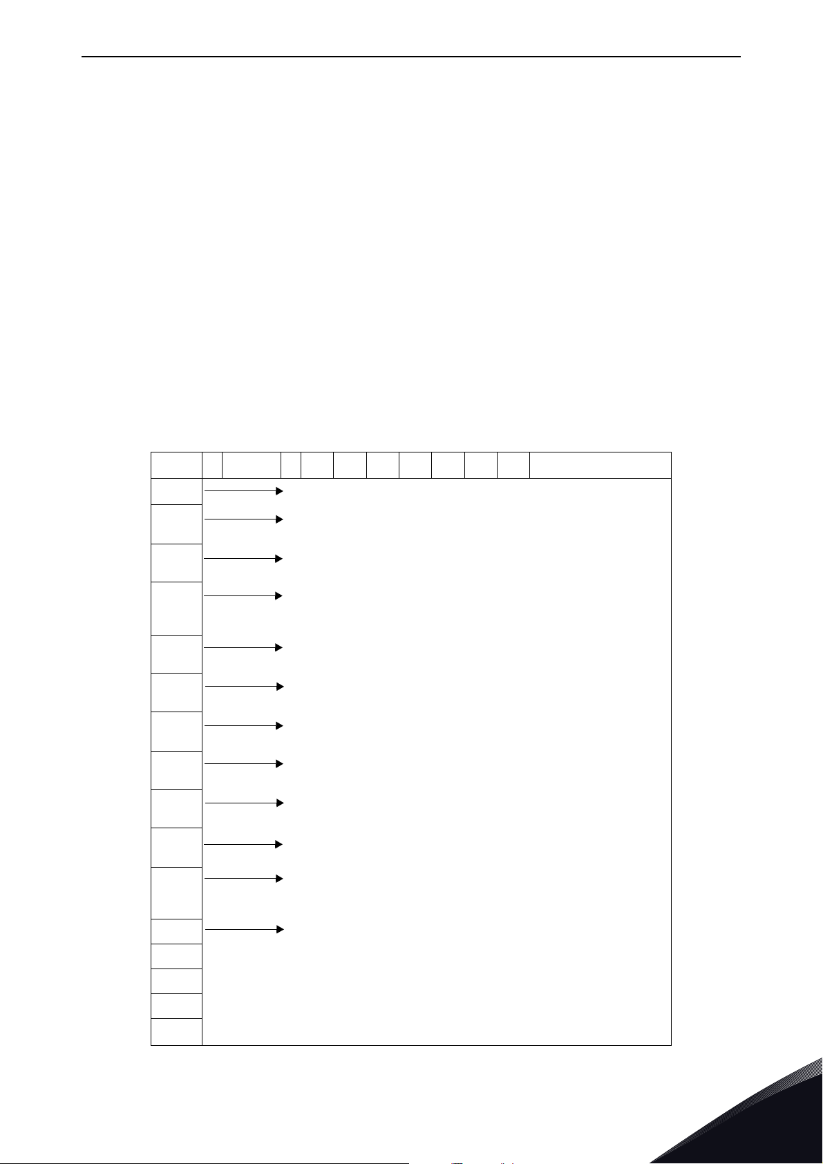
3. RECEIPT OF DELIVERY
Vacon® NX Active Front End has undergone scrupulous tests and quality checks at the factory
before they are delivered to the customer. However, after unpacking the product, check that no
signs of transportation damage are to be found on the product and that the delivery is complete
(compare the type designation of the product to the codes below, See Figure 1, Figure 2, Table 2).
Should the product have been damaged during the shipping, please contact primarily the cargo
insurance company or the carrier.
If the delivery does not correspond to your order, contact the supplier immediately.
3.1 Type designation code for the AFE unit
In Vacon type designation code for Common DC Bus components, the Active Front End Unit is
characterised by letter A and number 2. If the Active Front End unit is ordered by number 2 delivery
does not include anything else than the unit itself.
NOTE! The delivery does not include the auxiliary devices, which are needed for the operation (the
AC or DC fuses, the fuses bases, the main contactor or circuit breaker, etc.). The customer will take
care of the auxiliary devices.
VACON NX ACTIVE FRONT END - TYPE CODE
NX A AAAA V A 0 T 0 2 S F A1 A2 00 00 00
NX
A
AAAA
V
A
0Enclosure class
T EMC emission level
0 Internal brake shopper
2 Delivery include
S
Product Generation
Module type
A = AFE Active Front End
Nominal current (low overload)
eg. 0261 = 261 A, 1030 = 1030 A, etc.
Nominal supply voltage
5 = 380-500 VAC / 465-800 VDC
6 = 525-690 VAC / 640-1100 VDC
Control keypad
A = standard (alpha numeric)
0 = IP00, FI9-13
T = IT networks (EN61800-3)
0 = N/A (no brake chopper)
2 = AFE module
S = Standard air cooled drive
U = Standard air cooled power unit - external supply for main fan
F
A1 Option boards; each slot is represented by two characters:
A2
00
00
00
Hardware modifications; module type - S Boards
F = Fiber connection, standard boards, FI9-FI13
G = Fiber connection, varnished boards, FI9-FI13
A = Basic I/O board B = Expander I/O board
C = Fieldbus board D = Special board
Figure 1. Type designation code for the Active Front End
24-hour support +358 (0)201 212 575 • Email: vacon@vacon.com
3
Page 12
vacon • 10 Receipt of delivery
3.2 Type designation code for the LCL filter
LCL filters has two versions of cooling fan power supply, one without the integrated DC/DC power
supply and one with it. The LCL filter is characterized without the integrated DC/DC power supply
by letter A and with the integrated DC/DC power supply by letter B in version column, Figure 2.
VACON LCL FILTERS FOR AFE - TYPE CODE
VACON LCL AAAA V A 0 R 0 1 1 T
LCL
AAAA
V
A
0
0261 5
0460 5
1300 5
0170 6
0325 6
1030 6
Product range
LCL = LCL filter for AFE
Nominal current (low overload)
eg. 0460 = 460 A, 1300 = 130 A, etc.
Voltage class
5 = 380-500 VAC
6 = 525-690 VAC
Version (hardware)
A = DC fan without DC/DC power supply
B = DC fan with integrated DC/DC power supply
Enclosure class:
0 = IP00
R
0
1
1
T
Reserve
Reserve
Reserve
Cooling fan type
1 = DC fan
Manufacturer
T = Trafotek
Figure 2. Type designation code for the LCL filters
3
Tel. +358 (0) 201 2121 • Fax +358 (0)201 212 205
Page 13
Receipt of delivery vacon • 11
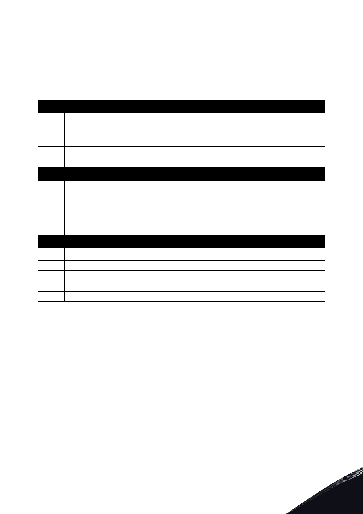
3.3 Type designation code for the pre-charging components
The pre-charging components can be ordered separately. The pre-charging resistors are optimized
for each Active Front End unit. Components of the pre-charging circuit are 2 pcs charging resistors,
the contactor, the diode bridge and the snubber capacitor, see Table 2. Each pre-charging circuit
has maximum charging capacity, see Table 20.
Table 2. Type designation code for the pre-charging components
FI9 AFE/CHARGING-AFE-FFE-FI9
Item Q’ty Description Manufacturer Product Code
1 1 Diode Bridge Semikron SKD 82
2 2 Charging resistors Danotherm CAV150C47R
3 1 Snubber capacitor Rifa PHE448
4 1 Contactor Telemecanique LC1D32P7
FI10 AFE/CHARGING-AFE-FFE-FI10
Item Q’ty Description Manufacturer Product Code
1 1 Diode Bridge Semikron SKD 82
2 2 Charging resistors Danotherm CBV335C20R
3 1 Snubber capacitor Rifa PHE448
4 1 Contactor Telemecanique LC1D32P7
FI13 AFE/CHARGING-AFE-FFE-FI13
Item Q’ty Description Manufacturer Product Code
1 1 Diode Bridge Semikron SKD 82
2 2 Charging resistors Danotherm CAV335C11R
3 1 Snubber capacitor Rifa PHE448
4 1 Contactor Telemecanique LC1D32P7
24-hour support +358 (0)201 212 575 • Email: vacon@vacon.com
3
Page 14

vacon • 12 Receipt of delivery
3.4 Storage
If Vacon® NX Active Front End is to be stored before use, make sure that the ambient conditions are
acceptable:
Storage temperature –40…+70 °C
Relative humidity <95%, no condensation
When the Active Front End unit is stored without voltage being applied, the recharging of the
capacitors should be done at least once a year by connecting voltage into the unit and keeping it
powered at least for 1hour.
If the storing time is much longer than one year, the recharging of the capacitors has to be carried
out so that the possible high leakage current through the capacitors is limited. The best alternative
is to use DC-power supply with adjustable current limit. Current limit has to be set for example to
300…500 mA and DC-power supply has to be connected to the B+/B- terminals (DC supply
terminals). DC-voltage must be adjusted up to nominal DC-voltage level of the unit (1.35*U
shall be supplied at least for 1 hour.
If DC power supply with current limiting is not available and unit has been stored much longer than
1 year de-energized, consult factory before connecting the power.
AC) and
n
3
Tel. +358 (0) 201 2121 • Fax +358 (0)201 212 205
Page 15

Receipt of delivery vacon • 13
3.5 Maintenance
All technical devices, drives as well, need a certain amount of care-taking and failure preventive
maintenance. To maintain trouble-free operation of the Vacon
environmental conditions, as well as load, line power, process control, etc. have to be within
specifications, determined by manufacturer.
If all conditions are in accordance with the manufacturer's specifications, there are no other
concerns, but to provide a cooling capacity high enough for the power- and control circuits. This
requirement can be met by making sure, that the cooling system works properly. Operation of
cooling fans and cleanness of the heat sink should be verified regularly.
Regular maintenance is recommended to ensure trouble free operation and long lifetime of Vacon
NX Active Front End. At least the following things should be included in the regular maintenance.
Table 3. Maintenance interval
Interval Maintenance
12 months (if unit is stored) Capacitor reforming, see seperate instructions.
Check tightening torque of the input and output
terminals and I/O terminals.
Clean the cooling tunnel.
6 - 24 months (depending on environment)
Check operation of the cooling fan, check for
corrosion on terminals, bus bars and other
surfaces.
®
NX Active Front End,
®
Check the door filters.
Change the cooling fans.
5 - 7 years
5 - 10 years
It is also recommended to record all actions and counter values with dates and time for follow up
of maintenance.
Main fan of the unit.
Fan of the LCL filter.
Change the DC bus capacitors if DC voltage ripple
is high.
24-hour support +358 (0)201 212 575 • Email: vacon@vacon.com
3
Page 16

vacon • 14 Receipt of delivery
45
11179.emf
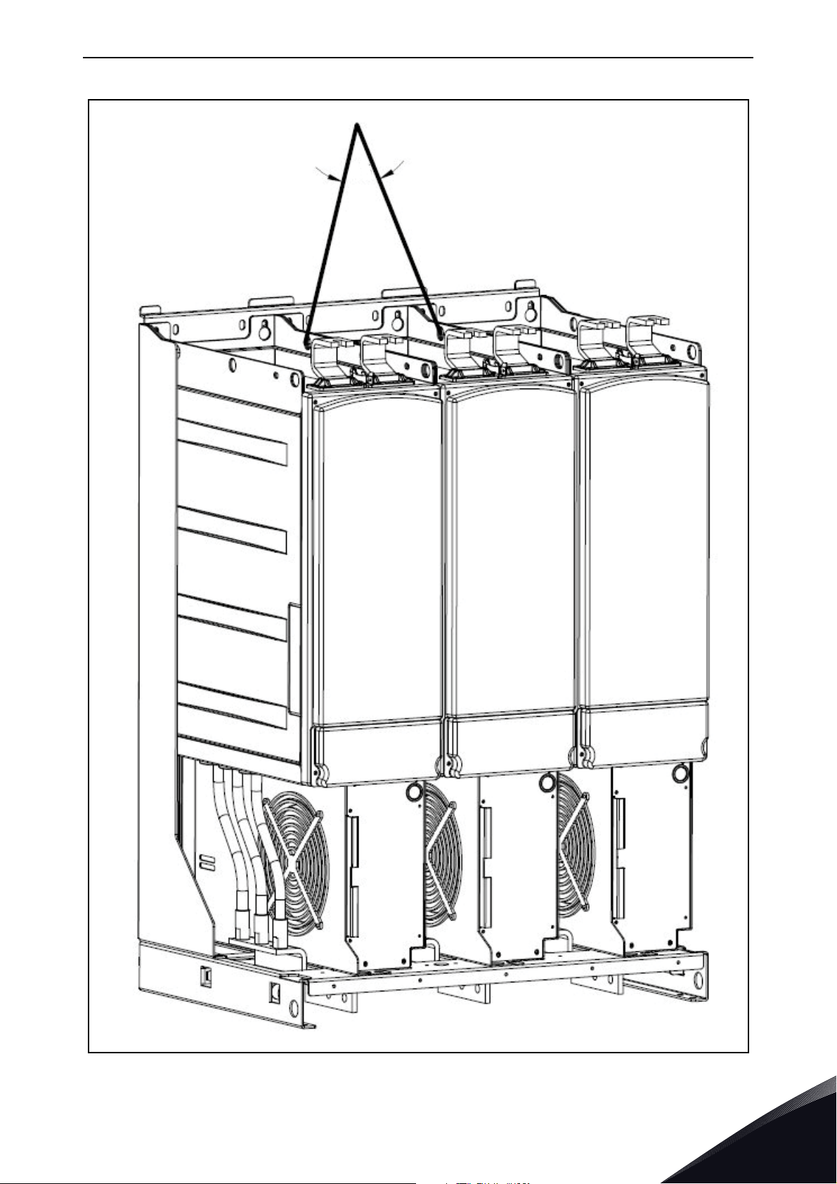
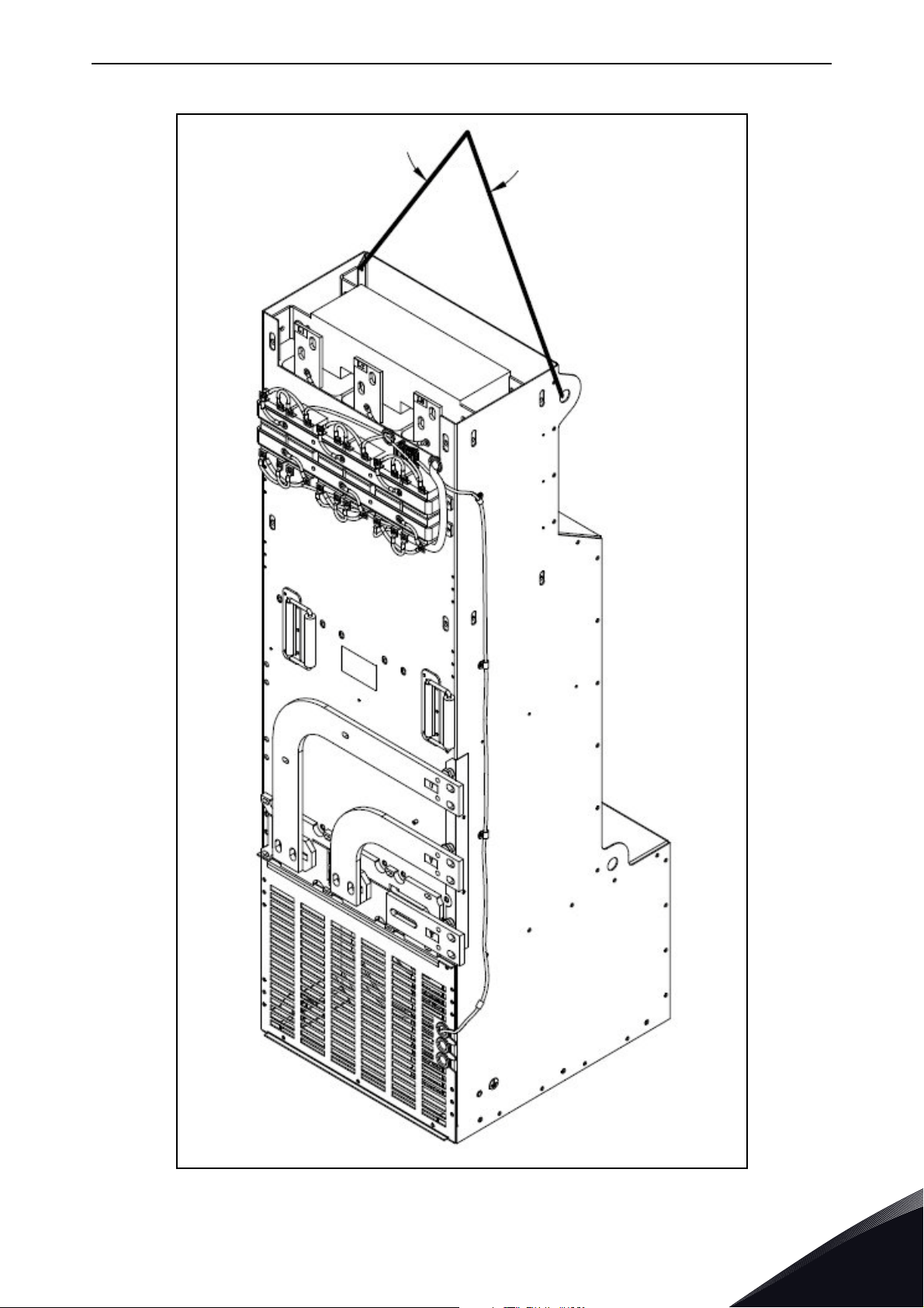
3.6 Lifting the modules
The modules can be lifted by the holes on top. Place the lifting hooks symmetrically in at least four
holes. The maximum allowed lifting angle is 45º. For frames FI9 and FI10, see Figure 3 and for the
frame FI13, see Figure 4.
The lifting equipment must be able to carry the weight of the module.
3
Figure 3. Lifting points for FI9 and FI10 modules
Tel. +358 (0) 201 2121 • Fax +358 (0)201 212 205
Page 17
Receipt of delivery vacon • 15
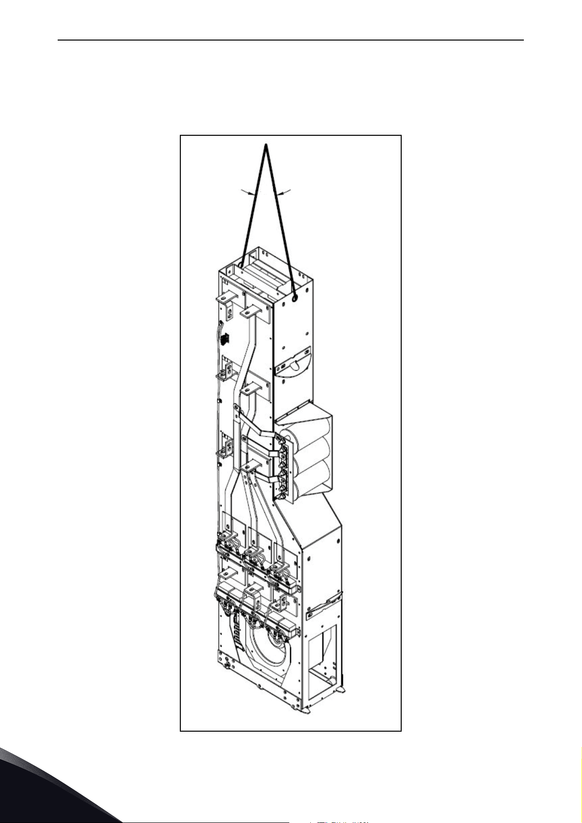
11178.emf
45
Figure 4. Lifting points for FI13 modules
24-hour support +358 (0)201 212 575 • Email: vacon@vacon.com
3
Page 18
vacon • 16 Receipt of delivery
11177.emf
45
3.7 Lifting the LCL filters
The modules can be lifted by the holes on top. Place the lifting hooks symmetrically in two holes in
the FI9 and FI10 LCL filters and four holes in the FI13 LCL filter. The maximum allowed lifting angle
is 45º. For the FI9 and FI10 LCL filter, see Figure 5 and for the FI13 LCL filter, see Figure 6.
3
Figure 5. Lifting points for FI9 and FI10 LCL filter
Tel. +358 (0) 201 2121 • Fax +358 (0)201 212 205
Page 19
Receipt of delivery vacon • 17
45
11176.emf
Figure 6. Lifting points for FI13 LCL filter
24-hour support +358 (0)201 212 575 • Email: vacon@vacon.com
3
Page 20

vacon • 18 Receipt of delivery
3.8 Warranty
Only manufacturing defects are covered by the warranty. The manufacturer assumes no
responsibility for damages caused during or resulting from transport, receipt of the delivery,
installation, commissioning or use.
The manufacturer shall in no event and under no circumstances be held responsible for damages
and failures resulting from misuse, wrong installation, unacceptable ambient temperature, dust,
corrosive substances or operation outside the rated specifications.
Neither can the manufacturer be held responsible for consequential damages.
The Manufacturer's warranty period is 18 months from the delivery or 12 months from the
commissioning whichever expires first (Vacon PLC general terms and conditions of sale).
The local distributor may grant a warranty time different from the above. This warranty time shall
be specified in the distributor's sales and warranty terms. Vacon assumes no responsibility for any
other warranties than that granted by Vacon itself.
In all matters concerning the warranty, please contact your distributor first.
3
Tel. +358 (0) 201 2121 • Fax +358 (0)201 212 205
Page 21
Active Front End (AFE) vacon • 19
NFE*
3
FFE*
3
2
3
INU
2
3
INU
2
3
INU
2
2
BCU
AFE*
*
alternative
2 2 2
11168.emf
Common DC bus
4. ACTIVE FRONT END (AFE)
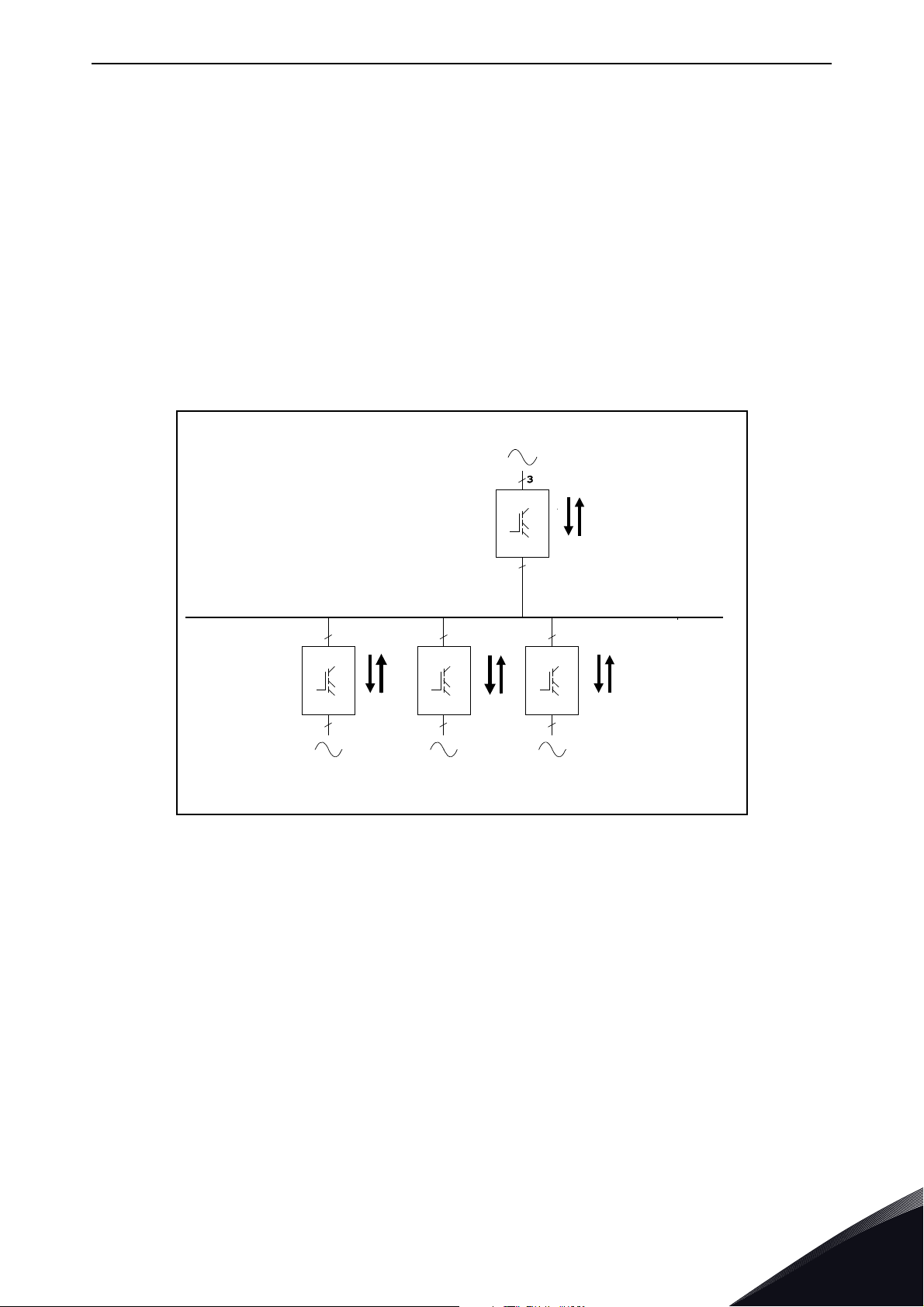
4.1 Introduction
The Vacon® NX Active Front End is used to transfer power between the AC input and intermediate
DC circuit. The Vacon NX Active Front End has a two-way function. This means that when power is
transferred from the AC input to the intermediate DC circuit, the Vacon NX Active Front End rectifies
the alternating current and voltage. When power is transferred from the intermediate DC circuit to
the AC input, the Vacon NX Active Front End inverts the direct current and voltage.
The difference between Vacon
low current distortion (THDI). In a typical Vacon NX Active Front End configuration, the desired
number of Inverters, Figure 7, are connected to the intermediate DC circuit.
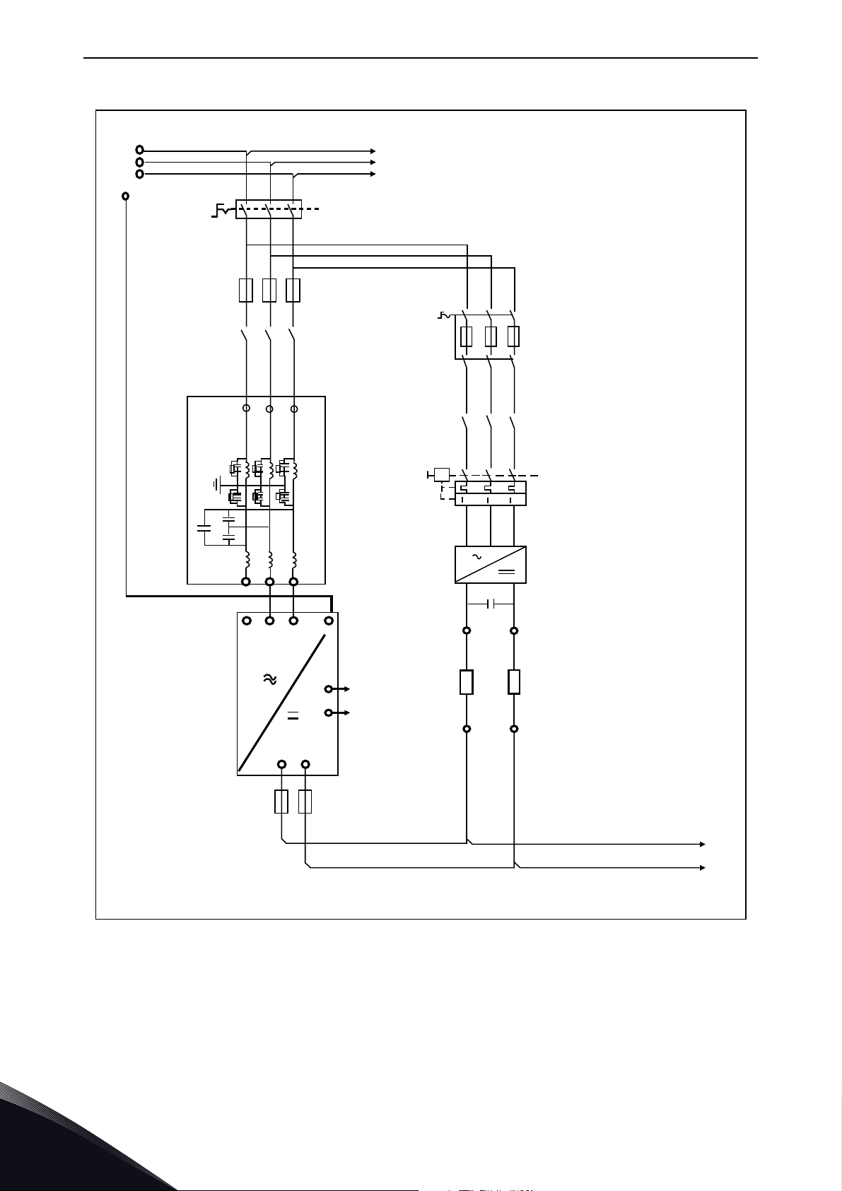
The Active Front End configuration consists of the unit itself, LCL filter, pre-charging circuit, control
unit, AC fuses, main contactor (or circuit-breaker) and DC fuses, Figure 8.
®
NX Active Front End and other Front Ends is that the unit creates
24-hour support +358 (0)201 212 575 • Email: vacon@vacon.com
Figure 7. Typical Active Front End configuration
4
Page 22
vacon • 20 Active Front End (AFE)
11169.emf
UUVVW
W
L1
L2
L3
L1
L2
L3
L1 L2 L3
+LCL-U1
+AFE-U1
NXA
XXXXX
PE
AP
OF
B+ B-
-F2,1
-X1
-R -R
1
11
22
3
4
-X1
-K3
-V3
+
-
4 5 6
1 2 3
1 2 3
2 4 6
2 4 6
1 3 5
1 3 5
-Q3
4 5 6
4 5 6
1 2 3
1 2 3
PE
DC+
DC-
3
2
-K1
-F1,1
-Q1
-Q2
21
22
Double Insulated
Double Insulated
Main Circuit
4
Figure 8. Vacon Active Front End Single Unit connections
Tel. +358 (0) 201 2121 • Fax +358 (0)201 212 205
Page 23
Active Front End (AFE) vacon • 21
B+
B-
U/T1
V/T2
W/T3
RS-232
11170.emf
Power Module
Control Module Keypad
Control
Driver
Measurements
Power
supply
Fan
ASIC
IGBT
bridge
I/O
slot E
I/O
slot D
I/O
slot C
I/O
slot A
I/O
slot B
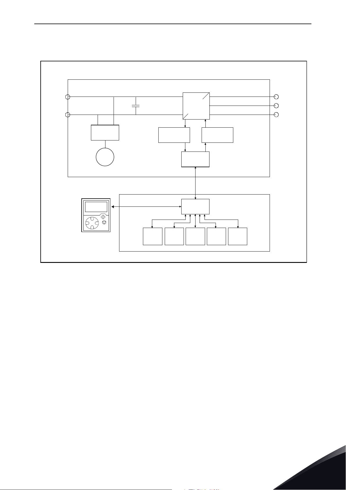
4.2 Active Front End Unit block diagram
Figure 9. NXA block diagram
24-hour support +358 (0)201 212 575 • Email: vacon@vacon.com
4
Page 24
vacon • 22 Active Front End (AFE)
11174.emf
11175.emf
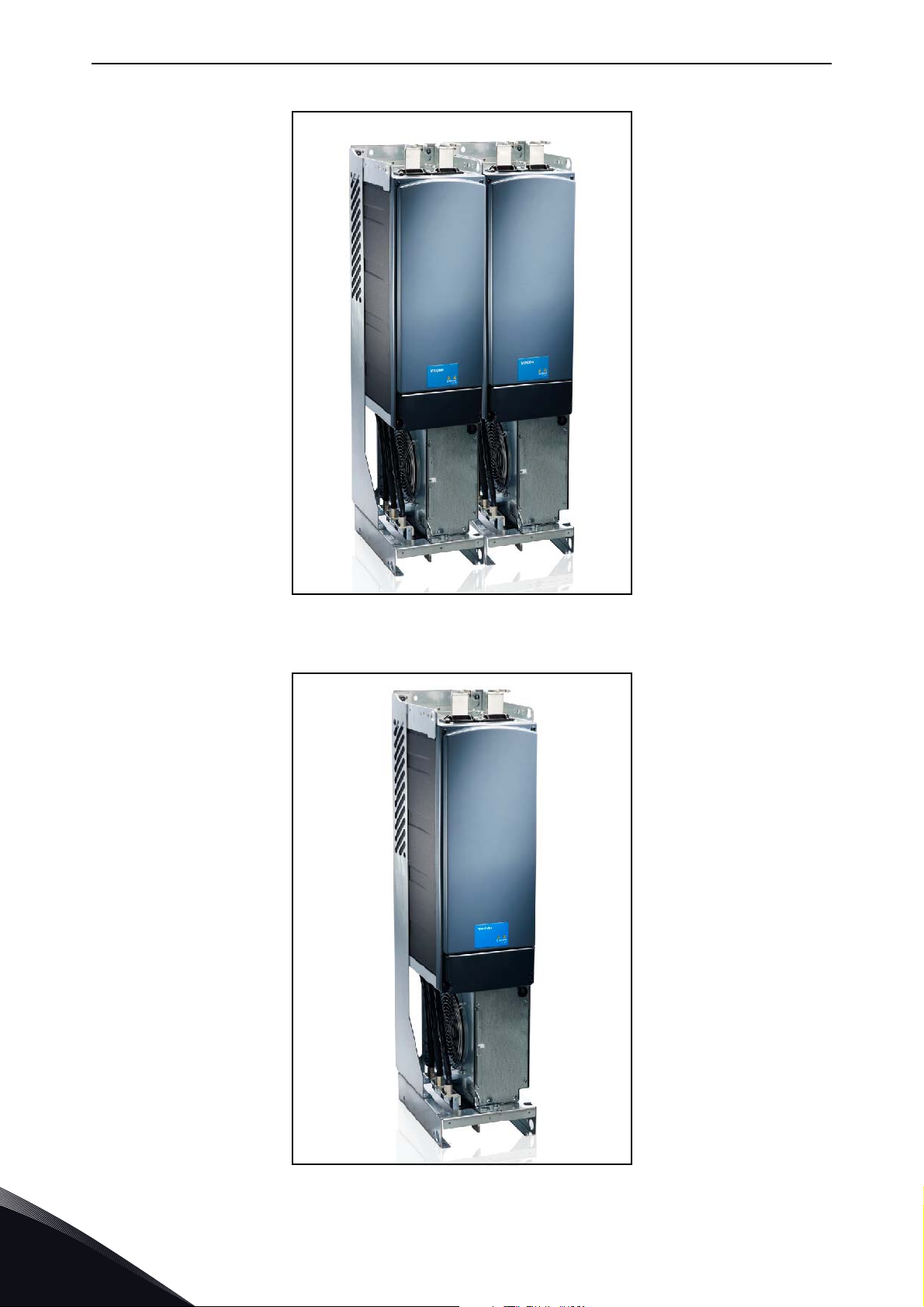
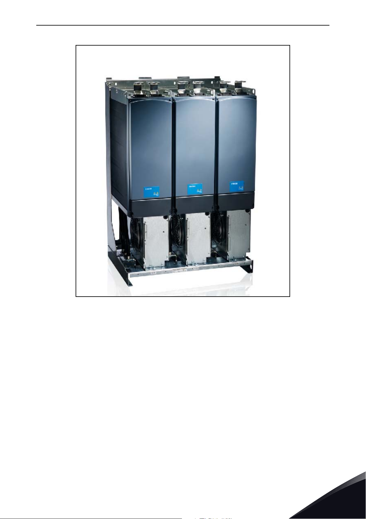
4.3 Active Front End frame sizes
Figure 10. Vacon NXA, FI9. Protection class IP00
4
Figure 11. Vacon NXA, FI10. Protection class IP00
Tel. +358 (0) 201 2121 • Fax +358 (0)201 212 205
Page 25
Active Front End (AFE) vacon • 23
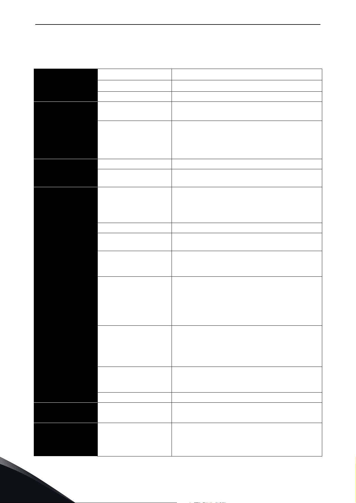
11173.emf
Figure 12. Vacon NXA, FI13. Protection class IP00
24-hour support +358 (0)201 212 575 • Email: vacon@vacon.com
4
Page 26
vacon • 24 Active Front End (AFE)
4.4 Active Front End unit technical data
Table 4. Technical specification for Vacon® NXA Active Front End unit
AC input connection
DC output
connection
Control
characteristics
Ambient conditions
Voltage U
in
Frequency f
in
380...500 Vac; 525...690 Vac; –10%…+10%
48–63 Hz
Starting delay FI9–FI13: 5 s
Voltage 1.35 x Uin x 1.1 (default DC link voltage boosting is
110%).
Continuous output
current
IH: Ambient temperature +40 °C,
overloadability 1.5 x I
I
: Ambient temperature +40 °C,
L
overloadability 1.1 x I
(1 min./10 min.).
H
(1 min./10 min.).
L
Control system Open Loop Vector Control
Switching frequency NXA_xxxx 5: 3.6 kHz
NXA_xxxx 6: 3.6 kHz
Ambient temperature
during operation
–10 °C (no freezing)…+40 °C: I
–10 °C (no freezing)…+40 °C: I
H
L
Maximum temperature +50 °C, see Power derating
as a function of ambient temperature.
Storage temperature –40 °C…+70 °C
Relative humidity 0 to 95% RH, non-condensing, non-corrosive, no
dripping water.
EMC (using factory
settings)
Safety
Air quality:
- chemical fumes
- solid particles
Elevation of place of
operation
EN 60721, equipment in operation, Class 3C3.
IEC 721-3-3, equipment in operation, Class 3S2.
100% loadability (no derating) up to 1000 m.
Maximum elevation 2000 m (525-690 VAC) and
4000 m (380-500 VAC),
Relay I/O: max. 240 V: 3000 m; max. 120 V: 4000 m,
see Power derating as a function of installation
altitude. See Chapter 4.16.
Vibration
EN50178/EN 60068-2-6
5…150 Hz.
Vibration amplitude 1 mm (peak) in frequency
range 3…15.8 Hz.
Max. acceleration 1 G in frequency range 15.8…150
Hz.
Impacts
EN 50178,
UPS drop test (with applicable UPS weights)
Storage and transport: max. 15 G, 11 ms (packed).
EN 60068-2-27
Enclosure class IP00/NEMA1 standard size in the kW/HP range.
Immunity
EN 61800-3 (2nd edition 2004), second
environment.
EN 50178 (1997), EN 60204-1 (1996-2009), EN
60950 (2000, 3. edition) (as relevant), CE, UL, cUL,
FI, GOST R, IEC-EN 61800-5; (for approvals, see the
unit nameplate).
4
Tel. +358 (0) 201 2121 • Fax +358 (0)201 212 205
Page 27
Active Front End (AFE) vacon • 25
Table 4. Technical specification for Vacon® NXA Active Front End unit
Analogue input voltage 0…+10 V, Ri = 200 kΩ.
Resolution 0.1%, accuracy ±1%
Analogue input current 0(4)…20 mA, Ri = 250 Ω differential
Digital inputs (6) Positive or negative logic; 18…30 VDC
Auxiliary voltage +24 V, ±15%, max. 250 mA
Control connections
Reference voltage,
output
Analogue output (1) 0(4)…20 mA; RL max. 500 Ω; Resolution 10 bit;
Digital outputs Open collector output, 50 mA / 48 V.
Relay outputs 2 programmable changeover relay outputs
+10 V, +3%, max. load 10 mA
Accuracy ±2%
Breaking capacity: 24 VDC / 8 A, 250 VAC / 8 A, 125
VDC / 0.4 A.
Min. switching load: 5 V / 10 mA.
Protection
Overvoltage protection
Undervoltage protection
Earth fault protection In case of earth fault in the supply cable, the earth
Input phase monitoring Trips if any of the input phases is missing.
Overcurrent protection Yes
Unit overheat protection Yes
Short-circuit protection
of +24 V and +10 V
reference voltages
NXA_5: 911 VDC; NXA_6: 1200 VDC
NXA_5: 333 VDC; NXA_6: 460 VDC
fault protection only protects the NX-AFE itself.
Yes
24-hour support +358 (0)201 212 575 • Email: vacon@vacon.com
4
Page 28
vacon • 26 Active Front End (AFE)
4.5 LCL filter technical data
Table 5. Technical specifications for Vacon LCL filter for Active Front End units
AC connections
Cooling fan With
integrated DC/DC-
power supply
Cooling fan with
external DC-power
supply
EMC (using factory
settings)
Safety
Voltage U
Frequency f
Continuous output current Same as the unit
Switching frequency LCLxxxx 5: 3.6 kHz
Input voltage U
Power consumption 220 W
Losses 20…30 W
Short-circuit protection DC fuses on the input side
Input voltage U
Current 5 A
Short-circuit protection AC fuses on the input side of the external
Immunity
Ambient temperature during
operation
in
in
in
in
Same as the unit
50 or 60 Hz +2%
LCLxxxx 6: 3.6 kHz
333...911 Vdc; 460...1200 Vdc
48 Vdc; -10...+10%
power supply.
EN 61800-3 (2nd edition 2004), second
environment.
Same as the unit
Same as the unit
Ambient conditions
Protection
Storage temperature Same as the unit
Relative humidity Same as the unit
Air quality:
- Chemical fumes
- Solid particles
Elevation of place of operation Same as the unit
Vibration
EN 50178/EN 60068-2-6
Impacts
EN 50178, EN 60068-2-27
Dissipation power Approximately 1%
Cooling fan rotation monitoring Yes (with integrated DC/DC power supply)
Over-temperature monitoring Ye s
Same as the unit
Same as the unit
Same as the unit
4
Tel. +358 (0) 201 2121 • Fax +358 (0)201 212 205
Page 29
Active Front End (AFE) vacon • 27
4.6 Application
The Vacon® NX Active Front End needs special application software, which is delivered with the NX
AFE unit. More information on the application can be found in Application User’s Manual.
4.7 Diagrams
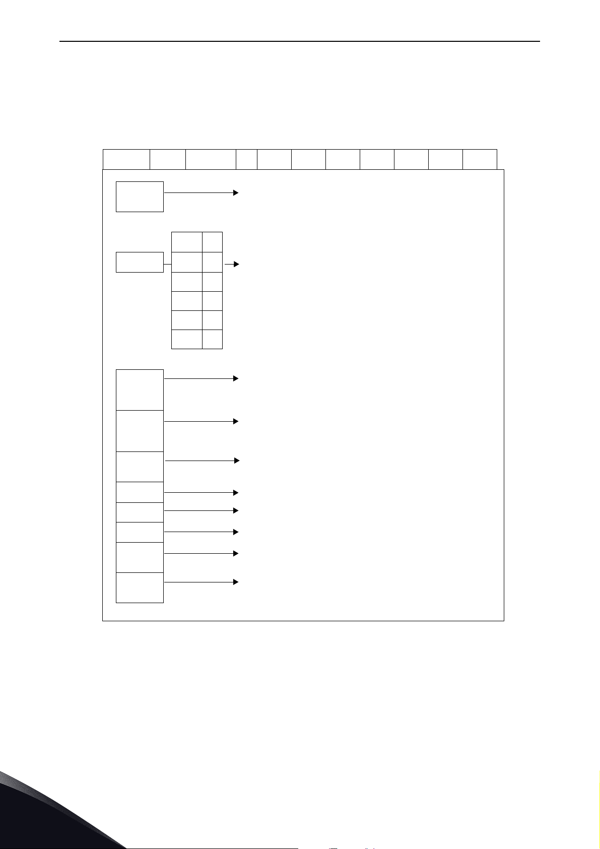
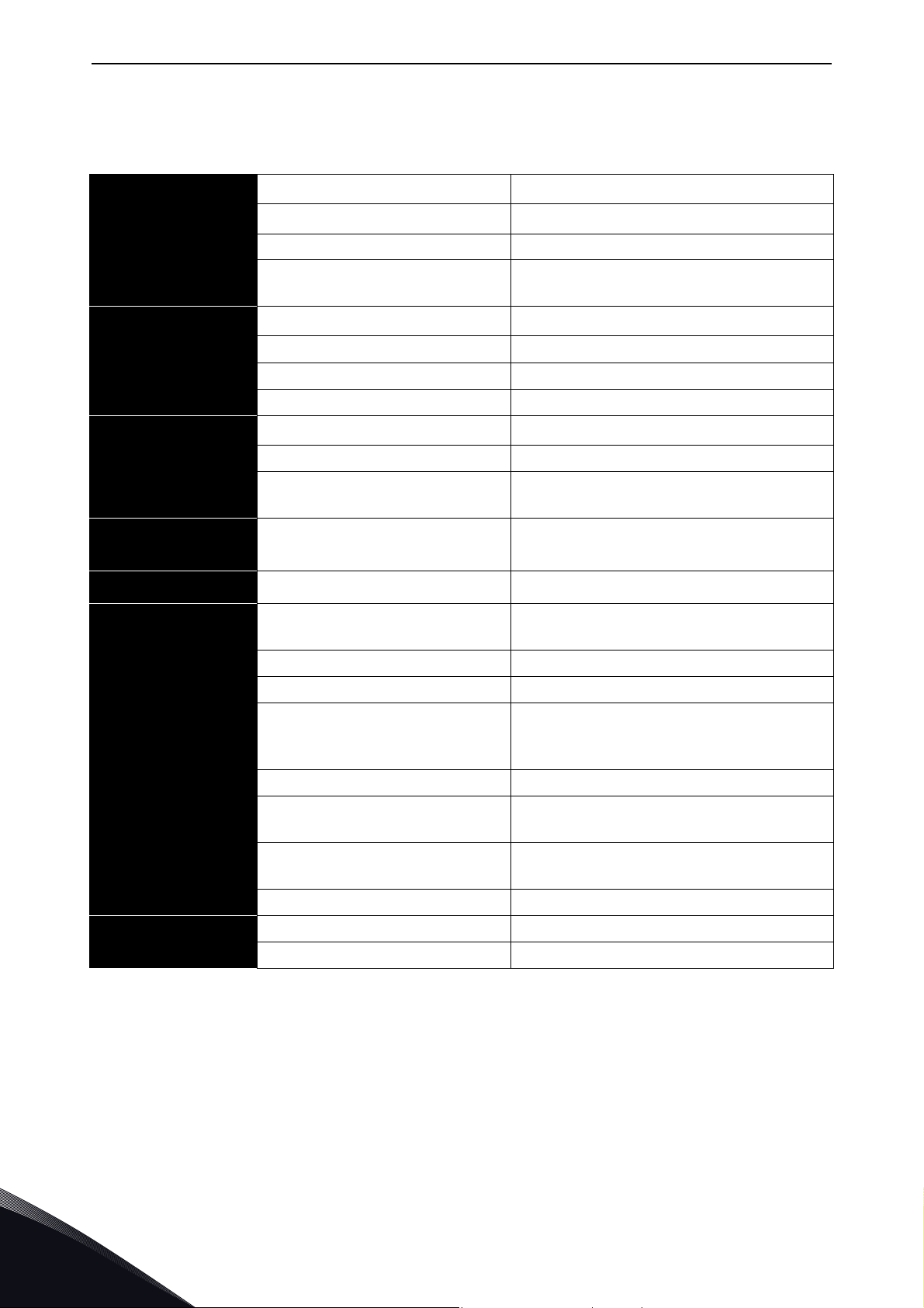
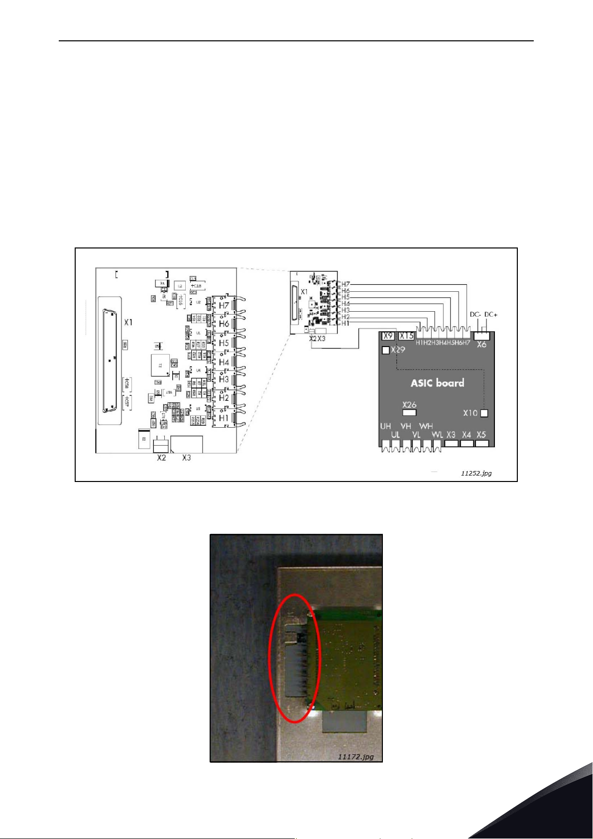
4.7.1 Connection between control unit and power unit
The communication connections between the Active Front End power unit and the
established using optical cable, Figure 13. The standard cable length of the optical cable is 1,5 m.
For optional the optical cables can get different lengths. The maximum length of the optical cable
is 10 m. The adapter board is located back side of the control unit, see Figure 14. ASIC board
terminals located in the unit under the black cover, Figure 15. To open black cover two screws at
left and right side should be opened.
control unit
is
Figure 13. Optical cable adapter board
Figure 14. Optical cable adapter board
24-hour support +358 (0)201 212 575 • Email: vacon@vacon.com
4
Page 30
vacon • 28 Active Front End (AFE)
Figure 15. Optical cable terminals in the unit (FI13 example)
Optical terminals on adapter board
H1
H2
H3
H4
H5
H6
H7
X1
X2
X3
Gate control enable
Phase U control
Phase V control
Phase W control
ADC synchronization
VaconBus data from control board to ASIC
VaconBus data from ASIC to control board
Other terminals on adapter board
Control board connection
Supply voltage 24 Vin (from power unit ASIC)
Supply voltage 24 Vin (customer);
•Max. current 1A
• Terminal #1: +
• Terminal #2: –
4
NOTE! The minimum fibre cable bending radius is 50 mm.
NOTE! Terminals
control I/O terminals (e.g. from board OPT-A1) is used, this terminal must be protected with a diode.
4.7.2 LCL wiring diagram
The LCL filter contains a choke on the mains side, capacitors and a choke on the AFE side,
Figure 16. The LCL also includes capacitors connected against ground potential. There are
resistors connected across the capacitors for discharging them when the LCL filter is disconnected
from the input power. The discharging resistors are 10 MΩ, 500 V and 0,5 W.
X2 and X3 can be in use simultaneously. However, if the +24 V supply from the
Tel. +358 (0) 201 2121 • Fax +358 (0)201 212 205
Page 31

Active Front End (AFE) vacon • 29
LCL FILTER
U2
V2
W2
-R1 -R4
-L1
-L2.1
-L2.2
-L2.3
U1
V1
W1
U
V
W
-C1
-C2
-C3
L1
L2
L3
-C1.1 -C1.2
-C2.2-C2.1
-C3.1 -C3.2
-C4.1
-C4.2
-C5.1 -C5.2
-C6.1
-C6.2
-R2 -R5
-R3 -R6
11181.emf
Figure 16. Vacon LCL filter wiring diagram
4.7.2.1
Removing discharging resistors
If the LCL filter is used in a network fitted with an earth fault protection relay, these discharging
resistors should be removed. If the discharging resistors are not removed, the earth fault
monitoring device might indicate a very low leakage resistance. The resistors must be connected
so that the capacitors are discharged when disconnecting from the input power. The wiring diagram
of an alternative discharging circuit can be seen in Figure 18. Figure 17 shows the default wiring of
the LCL filter. The discharging resistors should be 10 kΩ, 500 V and 2 W. Failure to ensure the
discharging of capacitors results in a risk of electric shock! Without the discharge resistors, the
capacitors take a very long time to discharge.
Figure 19 (for FI9 and FI10) and Figure 20 (for FI13) have a blue marking on the lead that has to be
removed from each capacitor if the discharge resistor is not to be used.
Warning! If you do not allow a total discharge of the system before starting the modification, it is
likely that you will get an electric shock in spite of the fact the system is disconnected from the
power supply.
24-hour support +358 (0)201 212 575 • Email: vacon@vacon.com
4
Page 32

vacon • 30 Active Front End (AFE)
M
X3
X1
X52
X4
X8
X10
DC-
DC+
1
2
-FC2.1
SC FUSES
1
2
-FC2.2
1
2
-FC2.3
-RF4
L1 L2 L3
U V W
4
3
2
1
X52
4
1
2
3
X51
PE
-
+
X53
W PE
B-B+
V PE
B-B+
-TB1
U PE
B-B+
X3
X70
H1..H7
1
2
-FC3.1
1
2
-FC3.2
1
2
-FC3.3
1
2
-FC3.4
1
2
-FC3.5
1
2
-FC3.6
GND/PE GND/PE GND/PE
GND/PE
1
2
-FCD1
8A
1
2
-FCD2
8A
12345
6
-FC1
MAINS
BREAKER
I>
I>>I>I>>I>I>>
AP
OF
1L1
1L2
1L3
PE
DC_BUS
7101.emf
Figure 17. Wiring diagram of the default LCL filter
4
Tel. +358 (0) 201 2121 • Fax +358 (0)201 212 205
Page 33

Active Front End (AFE) vacon • 31
M
X3
X1
X52
X4
X8
X10
DC-
DC+
1
2
-FC2.1
SC FUSES
1
2
-FC2.2
1
2
-FC2.3
-RF4
L1 L2 L3
U V W
4
3
2
1
X52
4
1
2
3
X51
PE
-
+
X53
W PE
B-B+
V PE
B-B+
-TB1
U PE
B-B+
X3
X70
H1..H7
1
2
-FC3.1
1
2
-FC3.2
1
2
-FC3.3
1
2
-FC3.4
1
2
-FC3.5
1
2
-FC3.6
GND/PE GND/PE GND/PE
GND/PE
1
2
-FCD1
8A
1
2
-FCD2
8A
12345
6
-FC1
MAINS
BREAKER
I>
I>>I>I>>I>I>>
-FC1
2122616271
72
x1
x2
-R1
x1
x2
-R2
x1
x2
-R3
GND/PE
-X1.1
1 2 3
-X1.1
4 5 6
AP
OF
1L1
1L2
1L3
PE
DC_BUS
7102.emf
Figure 18. Wiring diagram of LCL and AFE circuit when used in IT network, or when AFE of other
4.7.2.2
If a PWM modulated rectifier from another manufacturer is connected to the same input transformer, the HF capacitor must be removed, because the HF capacitors will be filtering the high frequency disturbances from another manufacturer’s active front ends. It is recommended to always use
manufacturer is connected to same transformer secondary supply
Removing HF capacitors
own transformers if more than one manufacturer’s AFEs are used.
Figure 19 (for FI9 and FI10) and Figure 20 (for FI13) have a red marking on the lead that has to be
removed from each capacitor if the HF capacitors are not to be used. Removing the lead
disconnects the capacitors from ground potential.
24-hour support +358 (0)201 212 575 • Email: vacon@vacon.com
4
Page 34

vacon • 32 Active Front End (AFE)
Remove
Remove
11253_A.emf
Remove
Remove
11254_A.emf
Figure 19. HF capacitors in FI9 and FI10 LCL filter
4
Figure 20. HF capacitors in FI13 LCL filter
Tel. +358 (0) 201 2121 • Fax +358 (0)201 212 205
Page 35

Active Front End (AFE) vacon • 33
4.8 Active Front End power ratings
4.8.1 Vacon NXA; DC voltage 380–500 V
Table 6. Power ratings of Vacon NXA, supply voltage 380–500 VAC
Unit
Low oveload
(AC current)
High oveload
(AC current)
DC Power
(continuous)
Type
Code Frame I
L-cont [A]I1min [A]IH-cont [A]I1min [A]
400 V mains
P [kW]
500 V mains
P [kW]
NXA_0261 5 FI9 261 287 205 308 175 229
AFE
NXA_0460 5 FI10 460 506 385 578 309 387
NXA_1300 5 FI13 1300 1430 1150 1725 874 1092
For dimensions of NXA units, see Table 8 and LCL filters Table 9.
NOTE! The rated currents in a given ambient (+40 °C) temperature are achieved only when the switching
frequency is equal to the factory default.
NOTE! The motor output power: P
P
η
η
= AFEs DC power
dc
= efficiency of the inverter
INU
= efficiency of the motor
Motor
out=Pdc
x (η
INU
x η
Motor
).
4.8.2 Vacon NXA; DC voltage 525–690 V
Table 7. Power ratings of Vacon NXA, supply voltage 525–690 VAC
Unit
Low oveload
(AC current)
High oveload
(AC current)
DC Power
(continuous)
Type
Code Frame I
L-cont [A]I1min [A]IH-cont [A]I1min [A]
690 V mains
P [kW]
NXA_0170 6 FI9 170 187 144 216 197
AFE
NXA_0325 6 FI10 325 358 261 392 377
NXA_1030 6 FI13 1030 1133 920 1380 1194
For dimensions of NXA units, see Table 8 and LCL filters Table 9.
NOTE! The rated currents in a given ambient (+40 °C) temperature are achieved only when the switching
frequency is equal to the factory default.
NOTE! The motor output power: P
P
η
η
= AFEs DC power
dc
= efficiency of the inverter
INU
= efficiency of the motor
Motor
out=Pdc
x (η
INU
x η
Motor
).
24-hour support +358 (0)201 212 575 • Email: vacon@vacon.com
4
Page 36

vacon • 34 Active Front End (AFE)
4.9 Active Front End unit – Dimensions
Table 8. The NXA unit dimensions
Module Module Dimension
Type Frame Height [mm] Width [mm] Depth [mm] Weight [kg]
FI9 1030 239 372 67
AFE
NOTE! More detailed dimensions can be found Appendix 73, Appendix 74 and Appendix 75.
FI10 1032 239 552 100
FI13 1032 708 553 306
4.10 LCL filter – Dimensions
Table 9. LCL filter dimensions
Module Module Dimension
Type Frame Height [mm] Width [mm] Depth [mm] Weight [kg]
FI9 1775 291 515 241/245
LCL
NOTE! Weight is different for 500 V/690 V other dimensions are same for both voltage classes.
NOTE! More detailed dimensions can be found Appendix 76 and Appendix 77.
FI10 1775 291 515 263/304
FI13 1442 494 525 477/473
4
Tel. +358 (0) 201 2121 • Fax +358 (0)201 212 205
Page 37

Active Front End (AFE) vacon • 35
4.11 Active Front End unit – Fuse selection
4.11.1 Introduction
AC fuses are used to protect the input network in case the Active Front End unit or the LCL filter is
faulty. DC fuses are used to protect the Active Front End unit and the LCL filter in case there is a
short circuit in the DC buses. If DC fuses are not used, short-circuit in the DC buses will cause a
loading of the Active Front End unit. Vacon Plc will not assume any responsibility for damages
caused by insufficient protection.
4.11.2 Fuses; mains voltage 380–500 V
4.11.2.1 AC fuses
Table 10. Ferraz Shawmut AC fuse selection, mains voltage 380–500 Vac
Module AC fuses
Type Code Frame
NXA_0261 5 FI9 NH2UD69V500PV 690 500 2 3
AFE
NOTE! Fuses for FI9 and FI10 are blade type and for FI13 flush-end type. If some other type is needed, please
contact Vacon.
Type Code Frame
AFE
NOTE! All fuses are blade type. If some other type is needed, please contact Vacon.
NXA_0460 5 FI10 NH3UD69V800PV 690 800 3 3
NXA_1300 5 FI13 PC44UD75V22CTQ 750 2200 44 3
Table 11. Bussman AC fuse selection, mains voltage 380–500 Vac
Module AC fuses
NXA_0261 5 FI9 170M6202 1250 500 3SHT 3
NXA_0460 5 FI10 170M6277 1250 1000 3SHT 3
NXA_1300 5 FI13 170M6277 1250 1000 3SHT 3x3
Ferraz Shawmut
type [aR]*
Bussman
type [aR]*
UN
[V]
UN
[V]
IN
[A]
IN
[A]
Size Q'ty
Size Q'ty
24-hour support +358 (0)201 212 575 • Email: vacon@vacon.com
4
Page 38

vacon • 36 Active Front End (AFE)
4.11.2.2 DC fuses
Table 12. Ferraz Shawmut DC fuse selection, mains voltage 465–800 Vdc
Module DC fuses
Type Code Frame
Ferraz Shawmut
type [aR]*
UN
[V]
IN
[A]
NXA_0261 5 FI9 PC73UD13C500TF 1250 500 3 2
AFE
NXA_0460 5 FI10 PC73UD95V11CTF 950 1100 3 2
NXA_1300 5 FI13 PC84UD11C24CTQ 1100 2400 84 2
Table 13. Bussman DC fuse selection, mains voltage 465–800 Vdc
Module DC fuses
Type Code Frame
Bussman
type [aR]*
UN
[V]
IN
[A]
NXA_0261 5 FI9 170M6562 690 800 3GKN/50 2
AFE
NXA_0460 5 FI10 170M6566 690 1250 3GKN/50 2
NXA_1300 5 FI13 170M6566 690 1250 3GKN/50 3x2
NOTE! All fuses are flush-end type. If some other type is needed, please contact Vacon.
4.11.3 Fuses; mains voltage 525–690 V
4.11.3.1 AC fuses
Size Q'ty
Size Q'ty
Table 14. Ferraz Shawmut AC fuse selection, mains voltage 525–690 Vac
Module AC fuses
Type Code Frame
Ferraz Shawmut
type [aR]*
UN
[V]
IN
[A]
Size Q'ty
NXA_0170 6 FI9 PC71UD13C315PA 1250 315 1 3
AFE
NXA_0325 6 FI10 PC73UD13C630PA 1150 630 3 3
NXA_1030 6 FI13 PC84UD12C18CTQ 1150 1800 84 3
NOTE! Fuses for FI9 and FI10 are blade type and for FI13 flush-end type. If some other type is needed, please
contact Vacon.
Table 15. Bussman AC fuse selection, mains voltage 525–690 Vac
Module AC fuses
Type Code Frame
Bussman
type [aR]*
UN
[V]
IN
[A]
Size Q'ty
NXA_0170 6 FI9 170M4199 1250 400 1SHT 3
AFE
NXA_0325 6 FI10 170M6305 1250 700 3SHT 3
NXA_1030 6 FI13 170M6305 1250 700 3SHT 3x3
4
NOTE! All fuses are blade type. If some other type is needed, please contact Vacon.
Tel. +358 (0) 201 2121 • Fax +358 (0)201 212 205
Page 39

Active Front End (AFE) vacon • 37
4.11.3.2 DC fuses
Table 16. Ferraz Shawmut DC fuse selection, mains voltage 640–1100 Vdc
Module DC fuses
Type Code Frame
NXA_0170 6 FI9 PC71UD13C400TF 1250 400 1 2
AFE
Type Code Frame
AFE
NOTE! All fuses are flush-end type. If some other type is needed, please contact Vacon.
NXA_0325 6 FI10 PC73UD13C630TF 1250 630 3 2
NXA_1030 6 FI13 PC84UD11C20CTQ 1100 2000 84 2
Table 17. Bussman DC fuse selection, mains voltage 640–1100 Vdc
Module DC fuses
NXA_0170 6 FI9 170M4926 1250 400 1GKN/75 2
NXA_0325 6 FI10 170M8507 1250 700 3GKN/75 2
NXA_1030 6 FI13 170M8510 1100 1000 3GKN/75 3x2
Ferraz Shawmut
type [aR]*
Bussman
type [aR]*
UN
[V]
UN
[V]
IN
[A]
IN
[A]
Size Q'ty
Size Q'ty
24-hour support +358 (0)201 212 575 • Email: vacon@vacon.com
4
Page 40

vacon • 38 Active Front End (AFE)
4.12 Active Front End unit – Circuit breaker selection
The Active Front End can also be protected by a circuit-breaker. The recommended types of circuitbreakers are shown in Table 18. If a circuit-breaker from another manufacturer is used, it must be
equivalent to the circuit-breakers shown. Further information on the circuit-breakers shown is
available from the manufacturer. Circuit-breakers do not provide the same level of protection as
fuses. A circuit-breaker can be used without a main contactor. In this case, the Active Front End unit
controls the circuit-breaker instead of the contactor. The circuit-breakers shown are suitable for
equipment rated at 380 V–500 V or 525 V–690 V.
Table 18. Circuit breaker for Vacon NXA
Type T5H400FF3LS
T5H400FF3LS
MOE230V/T4-5
UVRC230V/T4-5
ES-6/T5
FI9
AUX-C3+1/T4-5
PB100/T4-5-3P
AUX-SA1-S51+1/T4-5
Type T5H630FF3LS
T5H630FF3LS
MOE230V/T4-5
UVRC230V/T4-5
ES-6/T5
FI10
AUX-C3+1/T4-5
PB100/T4-5-3P
AUX-SA1-S51+1/T4-5
Type T7S16FF3PR231LS
Spring chargin motor 220...250 V
AC/DC
AUX 2Q 400 V AC
SOR 220…240 V AC/DC
T7S16FF3PR231LS
FI13
UVR 220…240 V AC/DC
SCR 220..240 V AC/DC
AUX-RTC 250 V AC/DC
Trip reset 200-240 V AC/DC
AUX-SA 1 S51 T7-T7M
MCCB
Motor
Undervoltage rel. (cabled)
Spreaded ext. term. incl. PB100
Aux./alarm cont. (cabled)
Phase separators for upper/lower
terminals
S51 NC
MCCB
Motor
Undervoltage rel. (cabled)
Spreaded ext. term. incl. PB100
Aux./alarm cont. (cabled)
Phase separators for upper/lower
terminals
S51 NC
SPRING CHARGING MOTOR
AUX. CONTACT
SHUNT OPENING RELEASE
MOULDED CASE CIRCUIT BREAKER
UNDER VOLTAGE RELAY
SHUNT CLOSING RELEASE
READY TO CLOSE
TRIP RESET UNIT
AUX-SA 1 S51 T7-T7M
1SDA054349R1
1SDA054897R1
1SDA054891R1
1SDA055038R1
1SDA054911R1
1SDA054970R1
1SDA064518R1
1SDA054412R1
1SDA054897R1
1SDA054891R1
1SDA055038R1
1SDA054911R1
1SDA054970R1
1SDA064518R1
1SDA062116R1
1SDA062102R1
1SDA063548R1
1SDA063010R1
1SDA063552R1
1SDA063550R1
1SDA062109R1
1SDA062119R1
1SDA063553R1
4
Tel. +358 (0) 201 2121 • Fax +358 (0)201 212 205
Page 41

Active Front End (AFE) vacon • 39
4.13 Main contactor
If a main contactor is to be used, the types shown in Table 19 are recommended. If a contactor from
another manufacturer is used, it must be equivalent to the types shown. Further information on the
contactors shown is available from the manufacturer.
Table 19. Recommended main contactor types
Type
FI9
Type
FI9
Type
FI10
Type
FI10
Type
FI13
Type
FI13
FI9 Contactor / 500 V
A210-30-11-80 Contactor, 350 A/690 V, AC3 110 KW/400 V, 230 VAC-Coil
FI9 Contactor / 690 V
A185-30-11-80 Contactor, 275 A/690 V, AC3 132 KW/690V, 230 VAC-Coil
FI10 Contactor / 500 V
AF400-30-11-70 Contactor, 600 A/500 V, AC3 200KW/400V, 100…250 V AC/DC coil
FI10 Contactor / 690 V
AF300-30-11-70 Contactor, 500 A/690 V, AC3 250 KW/690 V, 100…250 V AC/DC coil
FI13 Contactor / 500 V
AF1650-30-11-70 Contactor, 1650 A/500 V, AC3 560 KW/400 V, 100…250 V AC/DC coil
FI13 Contactor / 690 V
AF1350-30-11-70 Contactor, 1350 A/690 V, AC3 --- KW/400 V, 100…250 V AC/DC coil
24-hour support +358 (0)201 212 575 • Email: vacon@vacon.com
4
Page 42

vacon • 40 Active Front End (AFE)
4.14 Pre-Charging circuit
The Active Front End unit requires an external pre-charging circuit. The purpose of the precharging unit is to charge the voltage in the intermediate circuit to a level sufficient for connecting
the Active Front End unit to the mains. The charging time depends on the capacitance of the
intermediate circuit and the resistance of the charging resistors. The technical specifications of
Vacon's standard pre-charging circuits are shown in Table 20. Pre-charging circuits are suitable
for 380-500 Vac and 525-690 Vac.
The Active Front End unit must not be connected to mains without pre-charging. In order to ensure
the correct operation of the pre-charging circuit, the input circuit-breaker or contactor, as well as
the pre-charging circuit contactor, must be controlled by the Active Front End unit. The input
circuit-breaker or contactor as well as the pre-charging circuit contactor must be connected as
shown in Appendix 70.
Table 20. Capacitance Min and Max value for Pre-charging circuit
Capacitance
Frame size Resistance
Min Max
FI9
FI10
FI13
If the capacitance of the intermediate circuit in the system exceeds the values shown, please
contact the nearest Vacon office.
The example shown in Appendix 70 uses a spring-return switch. The switch has positions 0-1START. The spring returns the switch from position START to position 1. To start the pre-charging,
the switch is turned from position 0 via 1 to START. When pre-charging starts, the switch can be
released and it returns to position 1. No other control measures are required. The Active Front End
application controls the main contactor of the system with Relay Output RO2, see Appendix 72.
When pre-charging of the intermediate circuit is ready the main contactor will be closed. The status
of the main contactor is monitored via digital input (Default is DIN4). As a default the main contactor
monitoring is ON but it can be set OFF with parameter. The main contactor should not be possible
close without pre-charging.
To open the main contactor, simply turn the switch to 0. The contactor should not be opened under
load. Opening the contactor under load will shorten its service life.
NOTE! Wirings what are used for connecting the pre-charging circuit to the intermediate circuit has
to be double insulated.
2x47R 4950 μF 30000 μF
2x20R 9900 μF 70000 μF
2x11R 29700 μF 128000 μF
4
NOTE! Enough space must be reserved around the resistors to ensure sufficient cooling. Don’t
place any heat sensitive components near the resistors.
Tel. +358 (0) 201 2121 • Fax +358 (0)201 212 205
Page 43

Active Front End (AFE) vacon • 41
4.15 Paralleling
The power of the input group can be increased by connecting several Active Front End units in
parallel. Paralleling refers to Active Front End units connected in the same input transformer.
Active Front End units of different power ratings can also be connected in parallel. No
communication bet-ween the units is required; they work independently. Vacon's standard LCL
filters must be used for paralleling. If filters other than Vacon's standard LCL filters are used in
Active Front End units connected in parallel, too large circulation currents may be generated
between the Active Front End units. Parameter P2.1.4
parallel AFE units. This parameter will also set
be also modified manually with parameter P2.2.2.
Each Active Front End unit connected in parallel must have its own short-circuit protection on AC
and DC sides. The fuses are selected in accordance with Section 4.11. When paralleling, attention
must be paid to the sufficient short-circuit capacity of the system.
The derating of Active Front End units connected in parallel is 5% of the DC power; this should be
taken into account when selecting the input unit.
If a device is to be isolated from the AC and DC voltages, and other Active Front End units connected
in parallel are also to be used, separate isolators are required in the AC input and DC output. The
AC input can be isolated using a compact circuit-breaker, an ordinary circuit-breaker or a fuse
switch. Contactors are not suitable for isolating the AC input because they cannot be locked in the
safe position. The DC output can be isolated using a fuse switch. The pre-charging circuit must also
be isolated from the AC input. A load isolation switch or safety isolation switch can be used for this.
The device can also be connected to mains even when the other devices connected in parallel are
already connected and running. In such a case, the isolated deice must first be pre-charged. When
that is done, the AC input can be switched on. After this, the device can be connected to the
interediate DC circuit.
DC Drooping
Parallel AFE
to 4%. The value of
must be set to “1/yes” for all
DC Drooping
can
4.15.1 Common pre-charging circuit
In case of paralleled Active Front End units, one common pre-charging circuit can be used, see
Figure 21. Standard pre-charging circuits can be used if the capacitance of the intermediate circuit
not exceeds maximum value. For example if three FI10 Active Front End units are connected
parallel, the pre-charging circuit for FI13 Active Front End unit can be used. If all paralleled Active
Front End units have a common circuit breaker, the breaker can be controlled by one of the Active
Front End units. If each paralleled Active Front End unit has its own circuit-breaker, each Active
Front End controls it’s own circuit. The circuit diagram for control, see Appendix 70 and Appendix
72.
24-hour support +358 (0)201 212 575 • Email: vacon@vacon.com
4
Page 44

vacon • 42 Active Front End (AFE)
11165.emf
PE
+LCL-U1
+AFE-U1
NXA xxxx x
DC+
DC-
+LCL-U2
+AFE-U2
NXA xxxx x
Main Circuit
Double Insulated
Double Insulated
Figure 21. Active Front End units parallel connection with one common pre-charging circuit
4
Tel. +358 (0) 201 2121 • Fax +358 (0)201 212 205
Page 45

Active Front End (AFE) vacon • 43
PE
+LCL-U1
+LCL-U2
11166.emf
+AFE-U1
NXA xxxx x
+AFE-U2
NXA xxxx x
DC+
DC-
Main Circuit
Double Insulated
Double Insulated
Double Insulated
Double Insulated
4.15.2 Each Active Front End unit has the pre-charging circuit
Each Active Front End can have its own pre-charging circuit. Each unit controls its own pre-charging
and main contactor. See Figure 22. One control switch can be used, but if an Active Front End unit
needs to be controlled independently, separate switches are needed. With this the system is more
redundant than with a common pre-charging circuit. The circuit diagram for control, see Appendix
70 and Appendix 72.
Ambient temperature, °C
Derating as a function
of ambient temperature
Loadability, %
Figure 22. Active Front End units parallel connection with own pre-charging circuits
24-hour support +358 (0)201 212 575 • Email: vacon@vacon.com
4
Page 46

vacon • 44 Active Front End (AFE)
50
60
70
80
90
100
110
0 102030405060
11167.emf
Loadability, %
Ambient temperature, °C
Derating as a function of ambient temperature
Loadability %
4.16 Derating
The output power has to be derated if one of following cases:
• Ambient temperature is more than 40 ºC.
• Installation altitude is more than 1000 m.
4.16.1 Ambient Temperature
The power rating of the Active Front End unit is valid for an ambient temperature of 40 ºC. If the
device is to be used in higher ambient temperatures, its power rating must be subjected to derating.
The derating coefficient is 1.5%/1 ºC, for ambient temperatures not exceeding 50 ºC. The reduced
power is calculated using the formula:
Pde = P
P
n
*((100% - (t - 40 ºC)*X)/100)
n
= nominal power of the unit
t = ambient temperature
x = derating coefficient
Figure 23. Derating as the ambient temperature
4.16.2 Installation altitude
The standard power ratings of the Active Frond End unit are valid for a maximum installation
4
altitude of 1 000 m. If the device is to be used in higher installation altitudes, its power ratings must
be subjected to derating. The derating coefficient is 1.5% per 100 m. The power rating of the device
can be reduced to a maximum installation altitude of 4000 m (500 V) and 2000 m (690 V). The reduced
power can be calculated using the formula:
Pde = p
P
n
h
inst
h
base
x = derating coefficient
*((100% -(
n
h
- h
inst
base
= nominal power of the unit
= intended installation altitude
= 1,000 m
)*X)/100)
Tel. +358 (0) 201 2121 • Fax +358 (0)201 212 205
Page 47

Active Front End (AFE) vacon • 45
0
20
40
60
80
100
120
0 500 1000 1500 2000 2500 3000 3500
11255.emf
4000
Derating as a function of installation altitude
Loadability %
Loadability, %
Installation altitude, m
84
86
88
90
92
94
96
98
100
102
0 500 1000 1500 2000 2500
11256.emf
Derating as a function of installation altitude
Loadability %
Loadability, %
Installation altitude, m
Figure 24. Derating as the installation altitude 380-500 V
Figure 25. Derating as the installation altitude 525-690 V
NOTE! If higher installation altitude is considered please contact Your nearest Vacon office.
24-hour support +358 (0)201 212 575 • Email: vacon@vacon.com
4
Page 48

vacon • 46 Installation
5. INSTALLATION
5.1 Mounting
The equipment mounting must be sturdy enough to carry the weight of the equipment. The
enclosure class of the equipment will depend on the mounting and solutions to be used. The
equipment mounting must provide sufficient shielding for contact of the live parts (IP2x). The
installation and mounting must comply with local laws and regulations.
5.1.1 Active Front End Unit
The Active Front End can be mounted in a vertical position on the back plane of a cubicle. Enough
space must be reserved around the Active Front End to ensure sufficient cooling, see Figure 33.
Follow the minimum dimensions for installation, see Table 21. Required cooling air capacity and
minimum air holes on the switchgear, see Table 22. Also make sure that the mounting plane is
relatively even. The Active Front End is fixed with four bolts, Figure 26, Figure 27 and Figure 28.
5
Figure 26. Mounting points of FI9 AFE unit
Tel. +358 (0) 201 2121 • Fax +358 (0)201 212 205
Page 49

Installation vacon • 47
Figure 27. Mounting points of FI10 AFE unit
24-hour support +358 (0)201 212 575 • Email: vacon@vacon.com
5
Page 50

vacon • 48 Installation
Figure 28. Mounting points of FI13 AFE unit
5.1.2 LCL filter
The LCL filter can only be mounted in a vertical position on the floor of a cubicle. Enough space must
be reserved around the LCL filter to ensure sufficient cooling, see Figure 36. Follow the minimum
dimensions for installation, see Table 23. Required cooling air capacity and minimum air holes on
the switchgear, see Table 24. LCL filters cooling air airflow is present in Figure 37 and Figure 38.
Also make sure that the floor is relatively even. The LCL filter must be attached properly so it can
not move.
In the LCL filter for the FI13 Active Front End unit, the connection direction can change from right
to left, see Appendix 77 and Appendix 78. Follow the instruction below:
1. Open fastenings numbered by 1 in Figure 29.
2. Open fastenings numbered by 2 in Figure 29.
3. Remove bus bars.
4. Remove the (dark grey) from the right side and place it in same place to the left.
5. Place the bus bars like in Figure 30.
6. Close fastenings numbered by 2 in Figure 30.
7. Close fastenings numbered by 1 in Figure 30.
5
Tel. +358 (0) 201 2121 • Fax +358 (0)201 212 205
Page 51

Installation vacon • 49
2
11185.emf
11186.emf
Figure 29. Right-side connection
2
Figure 30. Left-side conne ct i o n
24-hour support +358 (0)201 212 575 • Email: vacon@vacon.com
5
Page 52

vacon • 50 Installation
11188.emf
11187.emf
Ø
2
0
68
4 pcs Ø 5
38
308
10
R
5
8.5
300
5
82
18
126
7.5
8.5
5.1.3 Control Box
The control unit of the Active Front End unit is mounted into a mounting rack which then can be
placed inside the enclosure, Figure 31 and Figure 32. The control unit should be placed so that it is
easy to access. Vacon
alpha-numeric or graphical keypad can be used to control the Active Front
End unit. The keypad is connected to the control unit. The keypad can be mounted on the enclosure
door with optional door mounting kit, see Appendix 81. In that case the keypad connects to the
control unit with an RS232 cable. Pay special attention to the earthing of the cable, see the
instructions below.
Figure 31. Control unit installed into the mounting box; Left: front; Right: back
5
Figure 32. Mounting points of Control Box
Tel. +358 (0) 201 2121 • Fax +358 (0)201 212 205
Page 53

Installation vacon • 51
1. If the keypad sits in its place on the control unit, remove the keypad.
2. Connect the male end of the keypad cable to the D-connector of the control unit. Use Vacon
RS232 cable included in the delivery. Figure 1.
3. Run the cable over the top of the box and secure with plastic band on the backside. Figure 2.
4. Earthing of keypad cable
branch cable with a screw underneath the control unit. See Figures 3 and 4.
5. Mount the control unit mounting box in the front-left corner of the enclosure using two
screws as shown in Figure 5. NOTE! Do not install the mounting box floating (with e.g. plastic
screws).
6. Connect the optical cables (or the flat cable) to the power unit. See Chapter 4.7.1 Connection
between control unit and power unit and Figures 6 - 7.
7. Connect the female end of the keypad cable to keypad on the enclosure door, Figure 8. Use a
cable channel for the cable run, Figure 9.
: Earth the keypad cable in the mounting box frame by fixing the
24-hour support +358 (0)201 212 575 • Email: vacon@vacon.com
5
Page 54

vacon • 52 Installation
Figure 1. Figure 2. Figure 3.
Figure 4. Figure 5. Figure 6.
Figure 7. Figure 8. Figure 9.
5
Tel. +358 (0) 201 2121 • Fax +358 (0)201 212 205
Page 55

Installation vacon • 53
5.2 Cooling
5.2.1 Active Front End unit
Enough free space must be left around the Active Front End unit to ensure sufficient air circulation
and cooling. You will find the required dimensions for free space in the Table 21. You will find the
required cooling air, minimum air holes and heat dissipation in the Table 22.
When planning the cooling for the space, take into consideration that the Active Front End unit heat
loss is approx. 2% of the nominal capacity. Air flow, see Figure 34 and Figure 35.
Table 21. Mounting space dimensions
Dimensions [mm]
Type
NXA0261 5
NXA0170 6
NXA0460 5
NXA0325 6
NXA01300 5
NXA01030 6
A
200 0 0 100
200
200
B B
00
00
2
C
100
100
= free space above the unit
A
= distance between inverter and cabinet wall
B
= distance between two units
B2
= free space underneath of the units
C
24-hour support +358 (0)201 212 575 • Email: vacon@vacon.com
5
Page 56

vacon • 54 Installation
A
B
B2
C
C
B
A
2x FI9/FI10
FI9/FI10
11215.emf
Figure 33. Installation space for FI9, FI10 and FI13
5
Tel. +358 (0) 201 2121 • Fax +358 (0)201 212 205
Page 57

Installation vacon • 55
Figure 34. Cooling airflow for FI9 and FI10 units
24-hour support +358 (0)201 212 575 • Email: vacon@vacon.com
5
Page 58

vacon • 56 Installation
5
Figure 35. Cooling airflow for the FI13 unit
Table 22. Power losses and required cooling air for the Active Front End units
Minimum air holes on
switchgear (input and output)
(mm
2
)
Type
NXA_0261 5
NXA_0170 6
NXA_0460 5
NXA_0325 6
NXA_1300 5
NXA_1030 6
Heat dissipation
(W)
3540
3320
6160
6070
17920
19050
Cooling air required
3
(m
/h)
1150 50000
1400 60000
4200 180000
Tel. +358 (0) 201 2121 • Fax +358 (0)201 212 205
Page 59

Installation vacon • 57
B
B
B2
B2
A
A
C
C
11217.emf
5.2.2 LCL filter
Enough free space must be left around the LCL filter to ensure sufficient air circulation and cooling.
You will find the required dimensions for free space in the Table 23. You will find the required
cooling air, minimum air holes and heat dissipation in the Table 24.
When planning the cooling for the space, take into consideration that the LCL filter heat loss is
approx. 1% of the nominal capacity. Air flow, see Figure 37 and Figure 38.
Table 23. Mounting space dimensions
Dimensions [mm]
Type
LCL0261 5
A
350 0 20 0
B B
2
C
LCL0170 6
LCL0460 5
LCL0325 6
LCL1300 5
LCL1030 6
350
350
020
020
0
0
= free space above the LCL filter
A
= distance between LCL filter and cabinet wall
B
Figure 36. Installation space
24-hour support +358 (0)201 212 575 • Email: vacon@vacon.com
5
Page 60

vacon • 58 Installation
5
Figure 37. Cooling airflow for FI9 and FI10 LCL filters
Tel. +358 (0) 201 2121 • Fax +358 (0)201 212 205
Page 61

Installation vacon • 59
Figure 38. Cooling airflow guides for FI13 LCL filter
Table 24. Power losses and required cooling air for the LCL filters
Type
LCL0261 5
LCL0170 6
LCL0460 5
LCL0325 6
LCL1300 5
LCL1030 6
24-hour support +358 (0)201 212 575 • Email: vacon@vacon.com
Heat dissipation
(W)
2350
2050
3180
3290
6330
8680
Cooling air required
3
/h)
(m
1100 30000
1100 30000
1300 42000
Minimum air holes on
switchgear (input and output)
(mm
2
)
5
Page 62

vacon • 60 Installation
5.2.3 Arranging ventilation of the enclosure
The enclosure door must be provided with air gaps for air intake. To achieve sufficient cooling inside
the cabinet, the dimensions for the total area of free openings for incoming air given in Table 22 and
Table 24 must be followed. For instance, there could be two screened gaps as presented in
Figure 39 (Vacon's recommendation). This layout ensures a sufficient air flow to the module fans as
well as cooling of the additional components.
Air outlet gaps must be situated on top of the cabinet. The minimum effective air outlet area per unit
frame is given in Table 22 and Table 24. The cooling arrangements inside the cabinet must be such
that they prevent hot output air from mixing with the incoming fresh air (see Chapter 5.2.4).
The ventilation gaps must fulfill the requirements set by the selected IP class. The examples in this
manual apply to protection class IP21.
During operation, air is sucked in and circulated by a fan blower at the bottom of the power unit. If
the power unit is placed in the upper part of the cabinet, the fan blower will be in the mid of the
cabinet, at the height of the upper ventilation grid. In case of LCL filter air inlet 1.1 in Figure 39
cannot be used.
5
Figure 39. Cabinet openings for cooling
1. Cooling air inlets
2. Hot air exhaust
Tel. +358 (0) 201 2121 • Fax +358 (0)201 212 205
Page 63

Installation vacon • 61
Shields
Sheet metal
Touch
Mesh type touch
Air duct
protection
protections
11216.emf
5.2.4 Steering air flow
Cooling air must be taken in through the ventilation gaps on the door and blown out at the top of the
enclosure. To steer the hot air from the power unit to the outlet at the top of the enclosure and
prevent it from circulating back to the fan blower, use either of the following arrangements:
A. Install a closed air duct from the power unit to the outlet on top of the enclosure
(A in Figure 40).
B. Install shields in the gaps between the power unit and the cabinet walls (B in Figure 40).
Place the shields above the air outlet gaps at the sides of the module.
NOTE! If a flat roof is used, mount a V-shaped air guide on the underside of the roof to direct the air
flow horizontally. See Figure 41.
Figure 40. Cabinet cooling airflow guides
Figure 41. Roof structure seen from the side
24-hour support +358 (0)201 212 575 • Email: vacon@vacon.com
5
Page 64

vacon • 62 Installation
Sheet
metal
Shield
Shield
Front
Shield
Front
Shield
Shield
Back
Sheet metal
Figure 42. Cabinet cooling airflow guides for FI9 and FI10 AFE unit and LCL filter
5
Figure 43. Cabinet cooling airflow guides for FI13 AFE unit and LCL filter
The sheet metal airflow guides (deflectors) marked in green prevents air circulation between
different sections of the equipment. The shield guides marked in green prevent air circulation
inside a section. The points marked in red show the exhaust air holes. These holes must not be
covered, nor must anything be placed above them to stop the free exit of warm air from inside the
Tel. +358 (0) 201 2121 • Fax +358 (0)201 212 205
Page 65

Installation vacon • 63
equipment. The points marked in blue show the cooling air intake holes. These holes must not be
blocked in any way.
The materials used for preventing the circulation of air inside the equipment must be firerestraining. The edges must be sealed to prevent the formation of gaps. When the deflectors are
made according to the instructions, no separate cooling fan is required.
24-hour support +358 (0)201 212 575 • Email: vacon@vacon.com
5
Page 66

vacon • 64 Installation
5.3 Power connection
5.3.1 AC connection
The 3-phase input is connected to the input terminals of the LCL filter (L1, L2 and L3). The output
terminals of the LCL filter (U, V and W) are connected to the input terminals of the AFE unit (U, V
and W), Figure 8. The AC input of the AFE input group must be protected against short circuit. The
fuses suitable for protection are shown in Chapter 4.11. A circuit breaker can also be used for
protection, see Chapter 4.12. The best short-circuit protection is achieved by using fuses. The
short-circuit protection must be on the input side when seen from the LCL filter, Figure 8.
A cable or busbar designed for the purpose must be used to make the connection. The connection
must be dimensioned according to the nominal current rating of the Active Front End unit. The
necessary overloading allowance must also be used. The connection must also have the same
short-circuit capacity as the whole system. The connecting cable or busbar may be of copper or
aluminium. When aluminium is used, steps must be taken to prevent corrosion. The dimensions of
the terminals in the unit are indicated in Appendix 82 and their locations are shown in Appendix 73,
Appendix 74 and Appendix 75. Locations of terminals in the LCL filter are shown in Appendix 76 and
Appendix 77.
5.3.2 DC connection
The DC connection of the Active Front End unit is connected to the terminals at the top. The
terminals are marked as B+ for connection to DC+ and B- for connection to DC-. The DC connection
must be protected using DC fuses, see Chapter 4.11. The terminal dimensions are shown in
Appendix 82.
5.3.3 LCL filter Fan power supply
Two types of power supplies are available for the LCL filter cooling fan. The cooling fan can be
supplied from an external power supply or an integrated DC/DC power supply.
5.3.3.1 LCL filter with integrated DC/DC power supply for fan
The DC/DC power supply is integrated in the structure of the LCL filter, Figure 44 and Figure 45.
The integrated DC/DC power supply takes its input voltage from the intermediate circuit,
Appendix 79. The input of the DC/DC power supply must be protected against short circuit using DC
fuses type Ferraz Shawmut ATQ8 (8 A) if the length of the supply cable does not exceed 2 m. The
fuses can be installed in holders type Ferraz Shawmut US102I (2-pole), to allow the easy
disconnection of the DC/DC power supply from the supply. If the length of the supply cable exceeds
2 m, fuses type Ferraz Shawmut D100gRB008VI (8 A) must be used. The fuses should be installed
in holders.
The high DC voltage must be taken into account when wiring the supply; suitable cables/leads must
be used.
The DC/DC power supply is monitored and controlled by the Active Front End unit. The DC/DC power
supply connections are shown in Figures 44 - 45 and Appendix 79 and Appendix 80.
5
The control connection has to be taken from the Active Front End unit. The control cable has to be
connected to the terminal X51 on the LCL filter, see Figure 44 and Figure 45. The control cable has
to be connected to the terminal X3 on the Active Front End unit, see Figure 47. The terminal X3 can
be found under the black cover. In the FI13, the terminal X3 is located in the left-most unit. The
delivery includes the cable for the control connection. The length of the standard cable is 1,6 m.
The over-temperature protection can be wired directly to the control unit or to the DC/DC power
supply. The over-temperature protection must be connected to protect the filter for protect the
filter in case of over-temperature.
NOTE! By default, the over-temperature protection is not activated. If it is not activated, the LCL can
be damaged in case of over-temperature.
Tel. +358 (0) 201 2121 • Fax +358 (0)201 212 205
Page 67

Installation vacon • 65
If the over-temperature protection is connected to a digital input, the wires have to be removed from
the terminal X52. The I/O wiring has to be connected to the terminals 1 and 4 on the terminal X52,
see Appendix 80. If the over-temperature protection is connected to the I/O of the Active Front End
unit, it can be programmed. The parameter P2.2.1.3 has to be set to choose the digital input to which
the over-temperature monitoring is connected. The parameter P2.7.3 allows one to select the
response to an over-temperature alarm as wanted.
If the over-temperature protection is connected to the DC/DC power supply, the jumper has to be
removed from the terminal X3. The cable from the terminal X52 should be connected to the terminal
X3. By default, the jumper is connected to the terminal X3, see Figure 45. The delivery includes the
cable for connecting the terminals X52 and X3. The wiring diagram can be seen in Appendix 80. If
over-temperature monitoring is connected to the DC/DC power supply, the Active Front End unit
will monitor over-temperature. The response to an over-temperature alarm cannot be selected. In
this case, the over-temperature fault message will be same as the fan fault of the unit. On the
keypad, the fault “32 Fan Cooling” will be shown.
Figure 44. Integrated DC/DC-power in the FI9 and FI10 LCL filter
24-hour support +358 (0)201 212 575 • Email: vacon@vacon.com
5
Page 68

vacon • 66 Installation
DC‐DC+
11163.emf
X3
X3
X3
X81
X2
X8
X51X53
X1
X52
X70
AFE unit (V phase in FI13)LCL filter with integrated DC-DC supply
Fan supply
DC/DC
Fan supply
DC/DC
DC supply
Tempe-
rature
Switch
Fan
M
X51: (4-pin)
1 = (fan alarm)
2 = DC- (fuse base
connection)
3 = (fan control)
4 = +16,5 V
X52: (4-pin)
1 = Over-temperature
protection switch
4 = Over-temperature
protection switch
X53: (3-pin)
+ = DC+ (supply)
- = DC- (supply)
Figure 45. Integrated DC/DC-power in the FI13 LCL filter
5
Figure 46. Wiring diagram of integrated DC/DC-power
Tel. +358 (0) 201 2121 • Fax +358 (0)201 212 205
Page 69

Installation vacon • 67
52
X
X51
DIN2 DIN3
11164.emf
LCL filter with external DC/DC supply
DC supply
(48 Vdc)
Control unit
AFE unitLCL filter
X51: (4-pin)
1 = Over-temperature
protection switch
2 = Over-temperature
protection switch
3 = DC- (supply)
4 = DC+ (supply)
X52: (4-pin)
1 = Over-temperature
protection switch
4 = Over-temperature
protection switch
Tempe-
rature
Switch
Tempe-
rature
Switch
Fan
M
Over-temperature protection
Overtemperature
protection
Figure 47. Terminal X3 (U-phase in FI13) in the unit
5.3.3.2
LCL filter without DC/DC power supply for fan
The LCL filter is supplied without an integrated DC/DC power supply. In this case, the customer
must procure the power supply separately. The requirements for the DC power supply are shown
in Table 2. Short-circuit protection is implemented by protecting the input of the DC power with
fuses. When required, the cooling fan can be controlled on/off by installing a contactor in the DC
power supply input and controlling that depending on whether the main switch is open or closed.
The over-temperature protection of the LCL filter must always be wired from contacts 1 and 4 of
terminal X52 to a digital input of the control unit (see Appendix 81) and from contacts 1 and 2 of
terminal X51 to a digital input of the control unit. The wiring of the circuit is shown in Figure 48.
Figure 48. Wiring diagram of external DC-power
24-hour support +358 (0)201 212 575 • Email: vacon@vacon.com
5
Page 70

vacon • 68 Installation
11210.emf
5.4 Control unit
The control unit of Vacon® NX Active Front End consists of the control board and option boards (see
Figure 49 and Figure 50) connected to the five slot connectors (A to E) on the control board.
The control board is connected to the power unit through a D connector (1).
Figure 49. Control board Figure 50. Basic and option board
connections on the control board
5
Tel. +358 (0) 201 2121 • Fax +358 (0)201 212 205
Page 71

Installation vacon • 69
External
+24 V
11212.emf
When Vacon® NX Active Front End is delivered from the factory, the control unit usually includes
two basic boards (I/O board and relay board), which are normally installed in slots A and B. On the
next pages you will find the arrangement of the control I/O and the relay terminals of the two basic
boards, the general wiring diagram and the control signal descriptions. The I/O boards mounted at
the factory are indicated in the type code. For more information on the option boards, see Vacon NX
option board manual (ud741).
The control board can be powered externally (+24 V) by connecting the external power source to
bidirectional terminal #6. This voltage is sufficient for parameter setting and for keeping the
fieldbus active.
NOTE! If the +24 V input of several brake choppers or other loads are connected in parallel, we
recommend to use a diode in terminal #6 to avoid the current to flow in opposite direction, which
might damage the control board.
24-hour support +358 (0)201 212 575 • Email: vacon@vacon.com
5
Page 72

vacon • 70 Installation
L1 L2 L3
UVW
RO1/1
RO1/2
RO1/3
RO2/3
RO2/2
RO2/1
10Vref
GND
GND
+24V
AI1
AI2+
AI2 -
DIN1...
DIN3
CM A
DIN4...
DIN6
CM B
AO1+
AO2 -
DO1
n
k6_1 5
TI1+
TI1-
Control I/O
ground
Digital input
group A
Digital input
group B
Analogue
outp ut
Digital
outp ut
Control
board
Control
panel
Gat e d rivers
Powe r
board
11209.emf
5.5 Galvanic isolation barriers
The control connections are isolated from the mains potential and the GND terminals are
permanently connected to ground. See Figure 51.
The digital inputs are galvanically isolated from the I/O ground. The relay outputs are additionally
double-isolated from each other at 300 VAC (EN-50178). See Figure 51.
Figure 51. Galvanic isolation barriers
5
Tel. +358 (0) 201 2121 • Fax +358 (0)201 212 205
Page 73

Control Keypad vacon • 71
6. CONTROL KEYPAD
The control keypad is the link between Vacon®NX Active Front End and the user. The Vacon NX
control keypad features an alphanumeric display with seven indicators for the Run status (RUN,
, READY, STOP, ALARM, FAULT) and three indicators for the control place (I/O term/ Keypad/
BusComm). There are also three Status Indicator LED’s (green – green – red), see Chapter 6.1.2.
The control information, i.e. the menu number, description of the menu or the displayed value and
the numeric information are presented on three text lines.
The Vacon
Furthermore, the buttons can be used in setting parameters and monitoring values.
The keypad is detachable and isolated from the input line potential.
®
NX Active Front End is operable through the nine push-buttons of the control keypad.
24-hour support +358 (0)201 212 575 • Email: vacon@vacon.com
6
Page 74

vacon • 72 Control Keypad
READY
FAULTSTOP
RUN
Bus/Comm
Keypad
I/Oterm
ALARM
run
ready
fault
1 2 3 4 5 6
a bIc
3062.emf
enter
reset
select
12345
I
III
6.1 Indicators on the keypad display
Figure 52. Vacon control keypad and drive status indications
6.1.1 Drive status indications
The drive status symbols tell the user the status of the brake chopper. In addition, they tell about
possible irregularities detected by the brake chopper control software in brake chopper functions.
RUN = Indicates that the drive is running.
STOP = Indicates that the drive is not running.
READY =
ALARM =
FAULT =
Lights up when AC power is on. In case of a trip, the symbol will not light
up.
Indicates that the drive is running outside a certain limit and a warning is
given.
Indicates that unsafe operating conditions were encountered due to which
the drive was stopped.
6.1.2 Status LEDs (green – green – red)
The status LEDs light up in connection with the READY, RUN and FAULT drive status indicators.
Lights up with the AC power connected to the drive. Simultaneously, the drive status
I
II
=
indicator READY is lit up.
= Lights up when the drive is running (modulating).
Lights up when unsafe operating conditions were encountered due to which the
=
drive was stopped (Fault Trip). Simultaneously, the drive status indicator FAULT
blinks on the display and the fault description can be seen.
Tel. +358 (0) 201 2121 • Fax +358 (0)201 212 205
6
Page 75

Control Keypad vacon • 73
6.1.3 Text Lines
The three text lines (•, ••, •••) provide the users with information on their present location in the
keypad menu structure as well as with information related to the operation of the drive.
= Location indicator; displays the symbol and number of the menu, parameter, etc.
•
Example: M2 = Menu 2 (Parameters); P2.1.3 = Acceleration time.
••
•••
= Description line; Displays the description of the menu, value or fault.
= Value line; Displays the numerical and textual values of references, parameters, etc.
and the number of submenus available in each menu.
24-hour support +358 (0)201 212 575 • Email: vacon@vacon.com
6
Page 76

vacon • 74 Control Keypad
enter
reset
sele ct
11208.emf
reset
select
enter
+
-
6.2 Keypad push-buttons
The Vacon NX alphanumeric control keypad has 9 push-buttons that are used for controlling
®
Vacon
NX Active Front End, setting parameters, and monitoring values.
Figure 53. Keypad push-buttons
6.2.1 Buttons descriptions
= This button is used to reset active faults. See Chapter 6.3.4.
This button is used to switch between the two latest displays. This may be useful
=
when you want to see how the changed new value influences some other value.
The enter button is used for:
=
1) confirmation of selections.
2) fault history reset (2…3 seconds).
Browser button up.
=
Browse the main menu and the pages of different submenus.
Edit values.
Browser button down.
=
Browse the main menu and the pages of different submenus.
Edit values.
Menu button left
Move backward in menu.
=
Move cursor left (in parameter menu).
Exit edit mode.
Menu button right
Move forward in menu.
=
Move cursor right (in parameter menu).
Enter edit mode.
Start button
=
Pressing this button starts Vacon NX Active Front End (modulation) if the keypad
is the active control place. See Chapter 6.3.3.
Stop button
=
Pressing this button stops Vacon NX Active Front End (unless disabled by
parameter R3.4/R3.6). See Chapter 6.3.3.
6
Tel. +358 (0) 201 2121 • Fax +358 (0)201 212 205
Page 77

Control Keypad vacon • 75
Descriptio
available
V1
V14
READY
Local
RUN
Monitor
11206.emf
6.3 Navigation on the control keypad
The data on the control keypad is arranged in menus and submenus. The menus are used for the
display and editing of measurement and control signals, parameter settings (see Chapter 6.3.2) and
reference value and fault displays (see Chapter 6.3.4). Through the menus, you can also adjust the
contrast of the display (see Chapter 6.3.8.5).
Location
n
Number of items
The first menu level consists of menus M1 to M7 and is called the
in the Main menu with the
from the Main menu with the
displayed menu or page, you can see an arrow ( ) in the lower right corner of the display and can
reach the next menu level by pressing
The control keypad navigation chart is shown on the next page. Please note that menu M1 is located
in the lower left corner. From there you will be able to navigate your way up to the desired menu
using the menu and browser buttons.
You will find more detailed descriptions of the menus later in this chapter.
Browser buttons
Menu buttons
. When there still are pages to enter under the currently
Menu button right
up and down. The desired submenu can be entered
.
Main menu
. The user can navigate
24-hour support +358 (0)201 212 575 • Email: vacon@vacon.com
6
Page 78

vacon • 76 Control Keypad
FT1T7
STOP FAULT
I/Oterm
STOP
I/Oterm
FAULT
H1H3
READY
I/Oterm
T1T7
I/Oterm
READY
I/O t er m
READY
S1S9
STOP READY
I/Oterm
STOP READY
I/Oterm
enter
G1G5
READY
I/Oterm
A:NXOPTA1
READY
I/Oterm
G1G1
READY
I/O te rm
V1V15
READY
I/Oterm
RUN
13.95 Hz
READY
I/Oterm
RUN
G1G9
READY
I/Oterm
P1P15
READY
I/Oterm
13.95 Hz
READY
Local
P1P3
READY
I/Oterm
STOP
READY
I/Oterm
STOP
enter
enter
F0
STOP FAULT
I/Oterm
Parameters Basic parameters Min Frequency
11 Output phase Operation days
17
Fault history 11 Output phas e Operation days
System Menu Languag e
Change
value
Browse
Expander boards
Parameters
P1P3
Monitor Output fre quency
No editing!
Keypad control
Cont rol Place
I/O Terminal
Change
value
Change
value
Browse
Browse
Active faults
17
English
or:
11205.emf
Figure 54. Keypad navigation chart
6.3.1 Monitoring menu (M1)
You can enter the Monitoring menu from the Main menu by pressing
location indication M1 is visible on the first line of the display. Figure 55 shows how to browse
through the monitored values.
Menu button right
when the
The monitored signals carry the indication V#.# and they are listed in Table 25. The values are
updated once every 0.3 seconds.
This menu is meant only for signal checking. The values cannot be altered here. For changing
values of parameters, see Chapter 6.3.2.
6
Tel. +358 (0) 201 2121 • Fax +358 (0)201 212 205
Page 79

Control Keypad vacon • 77
V1
V14
READY
Local
13.95 Hz
READY
Local
13.95 Hz
READY
Loca l
RUN RUN
RUN
Monitor Output frequency
FreqReference
11204.emf
Figure 55. Monitoring menu
Table 25. Monitored signals
Code Signal name Unit Description
V1.1
V1.2
V1.3
V1.4
V1.5
V1.6
V1.7
V1.8
V1.9
M1.17
6.3.2 Parameter menu (M2)
Parameters are the way of conveying the commands of the user to Vacon
Parameter values can be edited by entering the Parameter Menu from the Main Menu when the
location indication M2 is visible on the first line of the display. The value editing procedure is
presented in Figure 56.
Frequency reference Hz
DC-link voltage V Measured DC-link voltage
Unit temperature ºC Heat sink temperature
Voltage input V AI1
Current input mA AI2
DIN1, DIN2, DIN3 Digital input statuses
DIN4, DIN5, DIN6 Digital input statuses
DO1, RO1, RO2 Digital and relay output statuses
Analogue output current mA AO1
Multimonitoring items Displays three selectable monitoring values. See
Chapter 6.3.8.4, Multimonitoring items (P6.5.4).
®
NX Active Front End.
Pressing
parameter group by using the
and it‘s parameters. Use the
Menu button right
You can now change the value in two different ways:
Menu button right
takes you to the edit mode. As a sign of this, the parameter value starts to blink.
once takes you to the Parameter Group Menu (G#). Locate the desired
Browser buttons
Browser buttons
and press
to find the parameter (P#) you want to edit. Pressing
Menu button right
24-hour support +358 (0)201 212 575 • Email: vacon@vacon.com
again to see the group
6
Page 80

vacon • 78 Control Keypad
11203.emf
• Set the desired value with the
button
•Press
may come in handy, when a relatively greater or smaller value than that on the display is
desired. Confirm the change with the
The value will not change unless the
back to the previous menu.
Several parameters are locked, i.e. cannot be edited, when Vacon NX Active Front End is in RUN
status. If you try to change the value of such a parameter the text
display. The Active Front End must be stopped to edit these parameters.
The parameter values can also be locked using the function in menu M6 (see Chapter 6.3.8.4,
Parameter lock (P6.5.2)).
You can return to the Main menu any time by pressing
You will find the parameter lists from the Active Front End Application manual.
Once in the last parameter of a parameter group, you can move directly to the first parameter of
that group by pressing
See the diagram for parameter value change procedure in Figure 56.
NOTE! You can connect power to the control board by connecting the external power source to the
bidirectional terminal #6 on the NXOPTA1 board (see Chapter 5.4). The external power source can
also be connected to the corresponding +24 V terminal on any option board. This voltage is sufficient
for parameter setting and for keeping the fieldbus active.
. Consequently, the blinking stops and the new value are visible in the value field.
Menu button right
Browser button up
Browser buttons
once more. Now you will be able to edit the value digit by digit. This
Enter button
Enter button
.
and confirm the change with the
.
is pressed. Pressing
Menu button left
Menu button left
*Locked*
will appear on the
for 1 to 2 seconds.
Enter
takes you
6
Figure 56. Parameter value change procedure
Tel. +358 (0) 201 2121 • Fax +358 (0)201 212 205
Page 81

Control Keypad vacon • 79
I/O ter m
Keypad
Bus/Comm
6.3.3 Keypad control menu (M3)
In the Keypad Control Menu
pressing
NOTE! There are some special functions that can be performed in menu M3:
Select the keypad as the active control place by pressing for 3 seconds when the Active
Front End is running (modulating). The keypad will become the active control place.
Select the keypad as the active control place by pressing for 3 seconds when the Active
Front End is stopped (modulating). The keypad will become the active control place.
NOTE! that if you are in any other than menu M3 these functions will not work.
If you are in some other than menu M3
button when the keypad is not selected as the active control place, you will get an error message:
Menu button right
Keypad Control NOT ACTIVE
6.3.3.1 Selection of control place
There are three different places (sources) where the Active Front End can be controlled from. For
each control place, a different symbol will appear on the alphanumeric display:
,
you can choose the control place. You can enter the submenu level by
.
and try to start the Active Front End by pressing the START
.
Control place Symbol
I/O terminals
Keypad (panel)
Fieldbus
You can change the control place by entering the edit mode with
then be browsed with the
See the diagram on the next page. See also Chapter 6.3.3 above.
6.3.4 Active fault menu (M4)
You can enter the Active faults menu
location indication M4 is visible on the first line of the keypad display.
When a fault brings the brake chopper to a stop, the location indication F1, the fault code, a short
description of the fault, and the fault type symbol (see Chapter 6.3.5) will appear on the display. In
addition, the indication FAULT or ALARM (see Figure 56 or Chapter 6.1.1) is displayed and, in case
of a FAULT, the red LED on the keypad starts to blink. If several faults occur simultaneously, the list
of active faults can be browsed with the
The memory of active faults can store a maximum of 10 faults in the order of appearance. The
display can be cleared with the
in before the fault trip. The fault remains active until it is cleared with the
reset signal from the I/O terminal.
Browser buttons
Reset button
. Select the desired control place with the
from the Main menu by pressing
Browser buttons
and the read-out will return to the same state it was
.
Menu button right
Menu button right
Reset button
. The options can
Enter button
when the
or with a
.
NOTE! Remove external Start signal before resetting the fault to prevent unintentional restart of the
drive.
24-hour support +358 (0)201 212 575 • Email: vacon@vacon.com
6
Page 82

vacon • 80 Control Keypad
Normal state,
no faults
F0
READY
I/Oterm
Active faults
11201.emf
11202.emf
6.3.5 Fault types
®
Vacon
NX Active Front End has four types of faults. These types differ from each other on the basis
of the subsequent behaviour of the drive. See Table 26.
Figure 57. Fault display
Table 26. Fault types
Fault type symbol Meaning
A
(Alarm)
This type of fault is a sign of an unusual operating condition. It does
not cause the drive to stop, nor does it require any special actions.
The 'A fault' remains in the display for about 30 seconds.
F
(Fault)
AR
(Fault Autoreset)
An 'F fault' makes the drive stop. Actions need to be taken to restart
the drive.
If an 'AR fault' occurs the drive will stop immediately. The fault is
reset automatically and the drive tries to restart the motor. Finally, if
the restart is not successful, a fault trip (FT, see below) occurs.
FT
(Fault Trip)
If the drive is unable to restart the motor after an AR fault an FT fault
occurs. The 'FT fault' has basically the same effect as the F fault: the
drive is stopped.
6
Tel. +358 (0) 201 2121 • Fax +358 (0)201 212 205
Page 83

Control Keypad vacon • 81
6.3.6 Fault codes
The fault codes, their causes and correcting actions are presented in the Table 27. The shadowed
faults are A faults only. The items in white on black background are faults for which you can
program different responses in the application. See parameter group Protections.
NOTE! When contacting the distributor or factory because of a fault condition, always write down all
texts and codes visible on the keypad display.
Table 27. Fault codes
Fault
code
1
2
7
8
9
13
14
Fault Possible cause Correcting measures
Overcurrent
Overvoltage
Saturation trip
System fault
Undervoltage
AFE
undertemperature
AFE
overtemperature
AFE has detected too high current
(>4*IH) in the resistor cables:
The DC-link voltage has exceeded the
limit:
911 V for 500 V AFE
1200 V for 690 V AFE
Various causes:
- Defective component.
- Brake resistor short-circuit
oroverload.
- Component failure
- Faulty operation
Note exceptional fault data record
Subcode in T.14:
S1 = Reserved
S2 = Reserved
S3 = Reserved
S4 = Reserved
S5 = Reserved
S6 = Reserved
S7 = Charging switch
S8 = No power to driver card
S9 = Power unit communication (TX)
S10 = Power unit communication
(Trip)
S11 = Power unit communication
(Measurement)
DC-link voltage is under the AFE fault
voltage limit:
333 VDC for 500 V AFE
460 VDC for 690 V AFE
- Most probable cause: too low
supply voltage in the system.
- AFE internal fault.
Heatsink temperature is under –10 °C
Heatsink temperature is over 90 °C.
Overtemperature warning is issued
when the heatsink temperature
exceeds 85 °C.
- Check cables.
- Check resistors.
- Cannot be reset from the keypad.
- Switch off power.
- DO NOT RE-CONNECT POWER!
- Contact your local distributor.
Reset the fault and restart.
Should the fault re-occur, contact your
local distributor.
- In case of temporary supply voltage
break, reset the fault and restart the
frequency converter.
- Check the supply voltage.
- If it is adequate, an internal failure
has occurred.
- Contact your local distributor.
- Check the correct amount and flow
of cooling air.
- Check the heatsink for dust.
- Check the ambient temperature.
24-hour support +358 (0)201 212 575 • Email: vacon@vacon.com
6
Page 84

vacon • 82 Control Keypad
Table 27. Fault codes
Fault
code
18
31
35
37
38
39
40
41
44
45
50
54
58
Fault Possible cause Correcting measures
Unbalance between power modules in
Unbalance
(Warning only)
IGBT temperature
(hardware)
Application Problem in application software
Device changed
(same type)
Device added
(same type)
Device removed
Device unknown
IGBT temperature
Device changed
(different type)
Device added
(different type)
External fault
Slot fault Defective option board or slot
PT100 fault
paralleled units.
Subcode in T.14:
S1 = Current unbalance
S2 = DC-Voltage unbalance
IGBT Inverter Bridge overtemperature
protection has detected too high a
short term overload current
Option board or control unit changed.
Same type of board or same power
rating of drive.
Option board or drive added.
Drive of same power rating or same
type of board added.
Option board removed.
Drive removed.
Unknown option board or drive.
Subcode in T.14:
S1 = Unknown device
S2 = Power1 not same type as
Power2
IGBT Inverter Bridge overtemperature
protection has detected too high a
short term overload current
Option board or control unit changed.
Option board of different type or different power rating of drive.
Option board or drive added.
Option board of different type or drive
of different power rating added.
Digital input fault.
Temperature limit values set for the
PT100 have been exceeded.
Should the fault re-occur, contact your
local distributor.
Contact your distributor. If you are
application programmer check the
application program.
Reset. Device is ready for use.
Old parameter settings will be used.
Reset. Device is ready for use.
Old board settings will be used.
Reset. Device no longer available.
Contact the distributor near to you.
Reset.
Set the option board parameters again
if option bard changed. Set converter
parameters again if power unit
changed.
Reset.
Set the option board parameters
again.
Remove fault situation from external
device.
Check board and slot.
Contact the nearest Vacon distributor.
Find the cause of temperature rise.
6
KLIXON Status of KLIXON input is LOW.
60
The thermistor input of option board
Thermistor fault
61
has detected too high resistor
temperature.
Check resistors.
Check thermistor connection (If
thermistor input of the option board is
not in use it has to be short circuited).
Tel. +358 (0) 201 2121 • Fax +358 (0)201 212 205
Page 85

Control Keypad vacon • 83
6.3.6.1 Fault time data record
When a fault occurs, the information described in Chapter 6.3.4 is displayed. By pressing
button right,
some selected important data valid at the time of the fault are recorded. This feature will help the
user or the service person in determining the cause of the fault.
The data available are;
you will enter the Fault time data record menu indicated by T.1T.#. In this menu,
Table 28. Fault time recorded data
Menu
T.1
T.2
T.3
T.8
T.9
T.10
T.11
T.12
Real time record
If real time is set to run on the brake chopper, the data items T1 and T2 will appear as follows:
T.1
T.2
Counted operation days
(Fault 43: Additional code)
Counted operation hours
(Fault 43: Counted operation days)
Output frequency
(Fault 43: Counted operation hours)
DC voltage V
Unit temperature °C
Run status
Direction
Warnings
Counted operation days yyyy-mm-dd
Counted operation hours hh:mm:ss,sss
(d)
(hh:mm:ss)
(d)
Hz
(hh:mm:ss)
6.3.7 Fault history menu (M5)
You can enter the Fault history menu from the
location indication M5 is visible on the first line of the keypad display.
All faults are stored in the Fault history menu where you can browse them with the
buttons
fault. You can return to the previous menu any time by pressing
the Active Front End can store a maximum of 30 faults in order of appearance. The number of faults
currently in the fault history is shown on the value line of the main page (H1H#). The order of the
faults is indicated by the location indication in the upper left corner of the display. The latest fault
is indicated by F5.1, the one before that by F5.2 and so on. If there are 30 uncleared faults in the
memory, the next fault will erase the oldest fault from the memory.
Pressing the
will change to 0.
. Additionally, the Fault time data record pages (see Chapter 6.3.6.1) are accessible for each
Enter button
for about 2 to 3 seconds resets the whole fault history. The symbol H#
Main menu
by pressing
Menu button left
Menu button right
. The memory of
when the
Browser
24-hour support +358 (0)201 212 575 • Email: vacon@vacon.com
6
Page 86

vacon • 84 Control Keypad
H1H3
READY
I/Oterm
T1T7
I/Oterm
READY
I/Oterm
I/Oterm
READY
13:25: 43
I/O t e r m
enter
17
Fau lt history 11 Output phase
5ChargeSwitch
Operation days
Ope ration hours
PUSH to reset
11200.emf
Figure 58. Fault history menu
6.3.8 System menu (M6)
You can enter the
location indication M6 is visible on the first line of the keypad display
System menu from the Main menu by pressing
Menu button right
.
when the
The controls associated with the general use of the Active Front End, such as application selection,
customised parameter sets or information about the hardware and software are located under the
System menu. The number of submenus and subpages is shown with the symbol S (or P) on the
value line.
The System menu functions are presented in the Table 29.
System menu functions
Table 29. System menu functions
Code Function Min Max Unit Default Selections
S6.1 Selection of language English English
Deutsch
Suomi
Svenska
Italiano
S6.2 Application selection Active Front
End
application
S6.3 Copy parameters
S6.3.1 Parameter sets Load factory defaults
Store set 1
Load set 1
S6.3.2 Load to keypad All parameters
Store set 2
Load set 2
S6.3.3 Load from keypad All parameters
6
All but motor parameters
Application parameters
Tel. +358 (0) 201 2121 • Fax +358 (0)201 212 205
Page 87

Control Keypad vacon • 85
Table 29. System menu functions
Code Function Min Max Unit Default Selections
P6.3.4 Parameter backup Yes No
Yes
S6.4 Parameter comparison
S6.5 Safety
S6.5.1 Password Not used 0 = Not used
P6.5.2 Parameter locking Change
Enabled
S6.5.3 Start-up wizard No
S6.5.4 Multimonitoring items Change
Enabled
S6.6 Keypad settings
P6.6.1 Default page
P6.6.2 Default page/OM
P6.6.3 Timeout time 0 65535 s 30
P6.6.4 Contrast 0 31 18
P6.6.5 Backlight time Always 65535 min 10
S6.7 Hardware settings
P6.7.1 Internal brake
resistor
P6.7.2 Fan control function Continuous Continuous
P6.7.3 HMI acknowledgment 200 5000 ms 200
P6.7.4 HMI: no. of retries 1 10 5
Connected Not connected
Change Enabled
Change Disabled
Yes
Change Enabled
Change Disabled
Connected
Temperature
S6.8 System information
S6.8.1 Total counters
C6.8.10.1. MWh counter kWh
C6.8.10.2. Operation day counter
C6.8.1.3. Operation hour counter
24-hour support +358 (0)201 212 575 • Email: vacon@vacon.com
6
Page 88

vacon • 86 Control Keypad
System Menu
S1S11
READY
I/Oterm
Language
English
READY
I/Oterm
Language
English
READY
I/Oterm
enter
READY
I/Oterm
Francais
Langue
11197.emf
6.3.8.1 Selection of language
The Vacon NX control keypad offers you the possibility to control the inverter through the keypad in
the language of your choice.
Locate the language selection page under the System menu. It‘s location indication is S6.1. Press
Menu button right
select another language for the keypad texts. Confirm with the
all text information on the keypad are presented in the selected language.
once to enter the edit mode. As the name of the language starts to blink you can
Enter button
. The blinking stops and
You can return to the previous menu any time by pressing
Figure 59. Selection of language
6.3.8.2
The parameter copy function is used when the operator wants to copy one or all parameter groups
from one drive to another. All the parameter groups are first
keypad is connected to another drive and then the parameter groups are
possibly back to the same drive). For more information, see on Page 87.
Copy parameters
Menu button left
uploaded
to the keypad, then the
downloaded
.
to it (or
Before any parameters can be successfully copied from one drive to another, the Active Front End
has to be stopped when the parameters are downloaded to it:
The parameter copy menu (S6.3) contains four functions:
Parameter sets (S6.3.1)
The user can reload the factory default parameter values and store and load two customised
parameter sets (all parameters included in the application).
On the Parameter sets page (S6.3.1), press
LoadFactDef
Enter button.
Alternatively, you can choose any other storing or loading functions with the
Confirm with the
6
Menu button right
begins to blink and you can confirm the loading of factory defaults by pressing the
The drive resets automatically.
Enter button
. Wait until 'OK' appears on the display.
to enter the
edit mode
. The text
Browser buttons
.
Tel. +358 (0) 201 2121 • Fax +358 (0)201 212 205
Page 89

Control Keypad vacon • 87
READY
READY
enter
READY READY
OK
Parameter sets
Select
Parameter sets
CANCEL
CONFIRM
Parameter sets
Wait...
Parameter sets
LoadFactDef
11198.emf
P1
P4
READY
READY READY
enter
READY READY
Copy Parameters
Up to keypad
Up to keypad
Select
CANCEL
CONFIRM
Up to keypad
Wait...
Up to keypad
OK
All p aram.
CHANGE VALU
11199.emf
Figure 60. Storing and loading of parameter sets
Upload parameters to keypad (To keypad, S6.3.2)
This function uploads all
Enter the To keypad page (S6.3.2) from the Parameter copy menu. Pressing
takes you to the edit mode. Use the
Enter button
the
Download parameters to drive (From keypad, S6.3.3)
This function downloads one or all parameter groups uploaded to the keypad to a drive provided
that the drive is in STOP status.
. Wait until 'OK' appears on the display.
existing parameter groups to the keypad provided that the drive is stopped.
Menu button right
Browser buttons
Figure 61. Parameter copy to keypad
to select the option
All parameters
and press
E
Enter the To
takes you to the edit mode. Use the
parameters
display.
The procedure to download the parameters from keypad to Active Front End is similar to that of
from Active Front End to keypad. See Figure 60.
or
24-hour support +358 (0)201 212 575 • Email: vacon@vacon.com
keypad page (S6.3.2) from the Parameter copy menu. Pressing the
Browser buttons
Application parameters
and press the
to select either
Enter button
. Wait until 'OK' appears on the
All parameters, All but motor
Menu button right
6
Page 90

vacon • 88 Control Keypad
C1C3
READY
READY
READY
0
enter
P1P6
P2.1.2= 50.0
READY
20.0 Hz
P2.1.2= 50.0
READY
20.0 Hz
ParamComparison
Set1
Set1
CONFIRM CHANGE
EDITVALUE
OR
11189.emf
Automatic parameter backup (P6.3.4)
On this page you can activate or inactivate the parameter backup function. Enter the edit mode by
pressing
Menu button right.
Select
Yes
or
No
with the
Browser buttons
.
When the Parameter backup function is activated Vacon NX control keypad makes a copy of the
parameters of the presently used application. When applications are changed, you will be asked if
you wish the parameters of the new application to be uploaded to the keypad. If you want to do this,
press the
Enter button.
If you wish to keep the copy of the parameters of the previously used
application saved in the keypad, press any other button. Now you will be able to download these
parameters to the Active Front End following the instructions given in Chapter 6.3.8.2.
If you want the parameters of the new application to be automatically uploaded to the keypad you
have to do this for the parameters of the new application once on page the
Upload parameters to
keypad (To keypad, S6.3.2) as instructed. Otherwise the panel will always ask for the permission to
upload the parameters.
NOTE! Parameters saved in the parameter settings on page the Parameter sets (S6.3.1) will be
deleted when applications are changed. If you want to transfer the parameters from one application
to another, you have to upload them first to the keypad.
6.3.8.3 Parameter comparison
In the Parameter comparison submenu (S6.4), you can compare the actual parameter values to the
values of your customised parameter sets and those loaded to the control keypad.
You can compare the parameter by pressing
Menu button right
in the Compare parameters
submenu. The actual parameter values are first compared to those of the customised parameter
Set1. If no differences are detected, '0' is displayed on the lowermost line. If any of the parameter
values differ from those of Set1, the number of the deviations is displayed together with symbol P
(for example, P1P5 = five deviating values). By pressing
Menu button right
once more, you can
enter pages where you can see both the actual value and the value it was compared to. In this
display, the value on the description line (in the middle) is the default value and the one on the value
line (lowermost) is the edited value. Furthermore, you can also edit the actual value with the
Browser buttons
in the
edit mode
which you can enter by pressing
Menu button right
once
.
6
Figure 62. Parameter comparison
Tel. +358 (0) 201 2121 • Fax +358 (0)201 212 205
Page 91

Control Keypad vacon • 89
READY
I/Oterm
0
READY
I/Oterm
enter
00
READY
I/Oterm
enter
Password
Not in use
Password Password
OR:
11190.emf
6.3.8.4 Safety
NOTE! The Security submenu (S6.5) is protected with a password. Store the password in a safe
place!
Password (S6.5.1)
The application selection can be protected against unauthorised changes with the Password
function (S6.5.1).
By default, the password function is not in use. If you want to activate the function, enter the edit
mode by pressing
password with the
Menu button right
Browser buttons
. A blinking zero appears in the display and you can set a
. The password can be any number between 1 and 65535.
NOTE! that you can also set the password by digits. In the edit mode, push
Menu button right
again
and Timeout time (P6.6.3) another zero appears on the display. Set ones first. To set the tens, press
Menu button right
, and so on. Confirm the password with the
Enter button
. After this, you have to
wait until the Timeout time (P6.6.3) (see Timeout time (P6.6.3) has expired before the password
function is activated.
If you try to change applications or the password itself, you will be prompted for the current
password. Enter the password with the
Browser buttons
.
You can deactivate the password function by entering the value 0.
Figure 63. Password setting
NOTE! Store the password in a safe place! No changes can be made unless a valid password is
entered.
Parameter lock (P6.5.2)
This function allows the user to prohibit changes to the parameters.
If the parameter lock is activated, the text
parameter value.
NOTE! This function does not prevent unauthorised editing of parameter values.
Enter the edit mode by pressing
parameter lock status. Confirm the change with the
pressing
24-hour support +358 (0)201 212 575 • Email: vacon@vacon.com
Menu button left.
Menu button right.
*locked*
will appear on the display if you try to edit a
Use the
Enter button
Browser buttons
or go back to the previous level by
to change the
6
Page 92

vacon • 90 Control Keypad
S1S9
READY
I/Oterm
READY
I/Oterm
READY
I/Oterm
enter
READY
I/Oterm
READY
I/Oterm
P1P4
System Menu
Security
Parameter Lock
ChangeEnable
Parameter Lock
ChangeDisabl
Parameter Lock
ChangeEnable
11191.emf
READY
I/Oterm
READY
I/Oterm
READY
I/Oterm
enter
Startup wizard Startup wizard
No No
Startup wizard
Yes
CANCEL
CONFIRM
11192.emf
READY
I/Oterm
READY
I/Oterm
enter
READY
I/Oterm
Multimon. items
ChangeEnable
Multimon. items Multimon. items
ChangeEnable ChangeDisable
11193.emf
Figure 64. Parameter locking
Start-up wizard (P6.5.3)
The Start-up wizard facilitates the commissioning of Vacon
®
NX Active Front End. If active, the
Start-up wizard prompts the operator for the language and application of his/her choice and then
displays the first menu or page.
Activating the Start-up wizard: In the System Menu, find page P6.5.3. Press
to enter the edit mode. Use the
Enter button.
parameter value
If you want to deactivate the function, follow the same procedure and give the
No
.
Browser buttons
to select
Yes
and confirm the selection with the
Menu button right
once
Figure 65. Activation of Start-up wizard
Multimonitoring items (P6.5.4)
Vacon NX alphanumeric keypad features a display where you can monitor up to three actual values
at the same time (see Chapter 6.3.1 and Chapter Monitoring values in the manual of the application
you are using). On page P6.5.4 of the System Menu, you can define whether the operator can replace
the values monitored with other values. See Figure 66.
Figure 66. Disabling the change of multimonitoring items
6
Tel. +358 (0) 201 2121 • Fax +358 (0)201 212 205
Page 93

Control Keypad vacon • 91
P1
P5
READY
I/Oterm
0.
READY
I/Oterm
Keypad s e ttings
Default page
11194.emf
0.
READY
I/Oterm
READY
I/Oterm
READY
I/Oterm
0.
1.
enter
Default page
REPEAT TO SET
DEFAULTSUBMENU/PAG
CANCEL
Default pageDefault page
CONFIRM CHANGE
11195.emf
6.3.8.5 Keypad settings
In the Keypad settings submenu under the System menu, you can further customise your Active
Front End operator interface
.
Locate the Keypad setting submenu (S6.6). Under the submenu, there are four pages (P#)
associated with the keypad operation:
Figure 67. Keypad settings submenu
Default page (P6.6.1)
Here you can set the location (page) to which the display automatically moves when the Timeout
time
(P6.6.3) (see Timeout time (P6.6.3)) has expired or the power is switched on to the keypad.
If the
Default
keypad display. Pressing
Main menu with the
right
. If the page you want to move to by default is at the third level, repeat the procedure. Confirm
the new default page with the
pressing
page is 0, the function is not activated i.e. the latest displayed page remains on the
Browser buttons
Menu button left
Menu button right
. To edit the number of the submenu/page, press
Enter button.
.
Figure 68. Default page function
takes you to the edit mode. Change the number of the
Menu button
You can return to the previous menu at any time by
E
Default page in the operating menu (P6.6.2)
Here you can set the location (page) in the Operating menu (in special applications only) to which
the display automatically moves to when the set Timeout time (P6.6.3) (see Timeout time (P6.6.3))
has expired or the power is switched on to the keypad.
See how to set the Default page (Figure 68).
Timeout time (P6.6.3)
The Timeout time setting defines the time after which the keypad display returns to the Default page
(P6.6.1). (See Default page (P6.6.1))
Enter the edit mode by pressing
Enter button
the
24-hour support +358 (0)201 212 575 • Email: vacon@vacon.com
. You can return to the previous menu at any time by pressing
Menu button right
. Set the desired timeout time and confirm it with
Menu button left
.
6
Page 94

vacon • 92 Control Keypad
90 s
READY
READY READY
90 s.
enter
60 s.
Timeout time
Timeout time Timeout time
CANCEL
CONFIRM CHANG
11196.emf
E
Figure 69. Timeout time setting
NOTE! If the
Default page
value is 0 the
Timeout time
setting has no effect.
Contrast adjustment (P6.6.4)
In case the display is unclear, you can adjust it‘s contrast through the same procedure as for the
timeout time setting, see Timeout time (P6.6.3).
Backlight time (P6.6.5)
By giving a value for the
Backlight time
, you can determine how long the backlight stays on before
going out. You can select any time between 1 and 65535 minutes or 'Forever'. For the value setting
procedure, see Timeout time (P6.6.3).
6
Tel. +358 (0) 201 2121 • Fax +358 (0)201 212 205
Page 95

Appendices vacon • 93
CHARGING
PULSE
CHARGING
CONTACTOR
MAIN
CONTACTOR
MAIN CIRCUIT
N 240VAC
L 240VAC
Project
Customer
Cust. ref.
Title
Circuit diagram
AFE FI9 and FI10
Prepared
Checked
Vacon Oyj
DCC
Based on
Proj. no
Sheet
Cont.
Object =
Loc. =
Revision
Doc. no
11225.pdf
DOUBLE INSULATED
DOUBLE INSULATED
7. APPENDICES
24-hour support +358 (0)201 212 575 • Email: vacon@vacon.com
Figure 70. Wiring diagram for FI9 and FI10
7
Page 96

vacon • 94 Appendices
11226.pdf
7
Figure 71. Wiring diagram for FI13
Tel. +358 (0) 201 2121 • Fax +358 (0)201 212 205
Page 97

Appendices vacon • 95
Project
Customer
Cust. ref.
Title
Prepared
Checked
Vacon Oyj
DCC
Proj. no
Based on
Doc. no
Revision
Object =
Loc. =
Sheet
Cont.
MAIN CONTACTOR MONITORING
EXTERNAL 24VDC SUPPLY
240VAC N
240VAC L
+AFE-U1
240VAC N
240VAC L
+24VDC
0VDC
11227.pdf
-D2
Figure 72. Wiring diagram for control circuit
24-hour support +358 (0)201 212 575 • Email: vacon@vacon.com
7
Page 98

vacon • 96 Appendices
11228.pdf
Mounting Holes
N8x25
Earthing bolt
back
952
659
372
116
1032
322
371
110, 5
211
123
7
Figure 73. FI9 Dimensions
Tel. +358 (0) 201 2121 • Fax +358 (0)201 212 205
Page 99

Appendices vacon • 97
x) Mounting holes
11229.pdf
952
1032
525
552
116
659
502
N8x25
Earthing bolt
back
230
230
211
Air
exhausting
hole
Figure 74. FI10 Dimensions
24-hour support +358 (0)201 212 575 • Email: vacon@vacon.com
7
Page 100

vacon • 98 Appendices
11230.pdf
x) Mounting holes
M8x25
Earthing bolt
back
553
1049
1012,5
Top view
1050
430
441
Air
exhausting
hole
Air
exhausting
hole
Air
exhausting
hole
85
13
16
17
40
7
Figure 75. FI13 Dimensions
Tel. +358 (0) 201 2121 • Fax +358 (0)201 212 205
 Loading...